WO2021215207A1 - 被介護者の情報を提供するためにコンピューターで実行される方法、プログラム、および、情報提供装置 - Google Patents
被介護者の情報を提供するためにコンピューターで実行される方法、プログラム、および、情報提供装置 Download PDFInfo
- Publication number
- WO2021215207A1 WO2021215207A1 PCT/JP2021/013648 JP2021013648W WO2021215207A1 WO 2021215207 A1 WO2021215207 A1 WO 2021215207A1 JP 2021013648 W JP2021013648 W JP 2021013648W WO 2021215207 A1 WO2021215207 A1 WO 2021215207A1
- Authority
- WO
- WIPO (PCT)
- Prior art keywords
- activities
- daily living
- displaying
- rehabilitation
- care recipient
- Prior art date
Links
Images


Classifications
-
- G—PHYSICS
- G16—INFORMATION AND COMMUNICATION TECHNOLOGY [ICT] SPECIALLY ADAPTED FOR SPECIFIC APPLICATION FIELDS
- G16H—HEALTHCARE INFORMATICS, i.e. INFORMATION AND COMMUNICATION TECHNOLOGY [ICT] SPECIALLY ADAPTED FOR THE HANDLING OR PROCESSING OF MEDICAL OR HEALTHCARE DATA
- G16H80/00—ICT specially adapted for facilitating communication between medical practitioners or patients, e.g. for collaborative diagnosis, therapy or health monitoring
Definitions
- This disclosure relates generally to the presentation of information, and more specifically to the presentation of information related to activities of daily living.
- Patent Document 1 discloses "systems and methods for monitoring human activities of daily living in an environment and ADL". There is. According to the technique disclosed in Patent Document 1, "The system receives a sensor output signal representing the detected value of at least one of the characteristics of human and environment, and generates an inferred ADL output signal representing human inferred ADL. It has an ADL inference unit that is adapted. The monitor unit is adapted to generate a monitor signal that depends on at least one of the received sensor output signal and the inferred ADL output signal. "(See [Summary]. ).
- a care recipient also referred to as a “resident” as appropriate
- the care recipient's family or care staff rather than the care recipient himself / herself, determines the condition of the person.
- This disclosure was made in view of the above background, and according to a certain aspect, a technique for objectively displaying the state of activities of daily living is disclosed.
- a computer-executed method is provided to provide information about the care recipient.
- This method accesses multiple movement data acquired by observing the activities of daily living of the care recipient multiple times, displays multiple movement data, and based on each movement data, daily life.
- the relevant information is displayed based on the display of information indicating the change in the degree of movement, the content of the rehabilitation performed for the care recipient, the content of the rehabilitation, and the change in the degree of activity of daily living. Includes outputting recommended rehabilitation for the care recipient.
- the method of following a certain aspect further includes accepting the selection of one or more activities of daily living from multiple activities of daily living.
- Displaying a plurality of motion data includes displaying motion data for one or more selected activities of daily living.
- Displaying information in a way that follows a certain aspect involves displaying a graph that represents the change.
- the method further comprises displaying in the graph one or more marks indicating that one or more rehabilitations have been performed by the care recipient in association with the date on which the rehabilitation was performed.
- Displaying one or more marks in a method that follows a certain aspect includes displaying a mark that identifies each of the plurality of rehabilitations performed on the care recipient.
- the method of following a certain aspect further includes displaying a comment showing the change in activities of daily living on which the graph is displayed.
- the method of following a certain aspect further includes accepting the designation of the day when any of multiple activities of daily living was performed.
- Displaying the contents of rehabilitation includes displaying the contents of rehabilitation performed on a designated day.
- the method of following an aspect further includes accepting an operation to change the date designated as the date on which any of the activities of daily living was performed.
- Displaying the content of rehabilitation includes displaying the content of rehabilitation performed on the day after the change in response to the operation of the change.
- the method of following a certain aspect further includes displaying information indicating a change in the degree of activities of daily living based on a plurality of movement data acquired for other care recipients.
- a program is provided that causes one or more processors to execute the method described in any of the above.
- an information providing device including the above program and a processor that executes the program is provided.
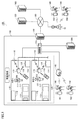
- FIG. 1 is a diagram showing an example of the configuration of the watching system 100.
- An example of the object to be watched over is a resident in each living room provided in the living room area of the facility 180.
- living rooms 110 and 120 are provided in the living room area.
- the living room 110 is assigned to the resident 111.
- the living room 120 is assigned to the resident 121.
- the monitoring system 100 includes a gateway server 130, an switching device 12, an access point 140, a management server 200, a sensor box 119, various devices communicating with the sensor box 119, and mobile terminals 161, 162, 163, 164. including.
- the gateway server 130 connects the internal network (intranet) of the facility 180 and the external network 16 of the facility 180 to each other.
- the external network 16 is, for example, the Internet or a public telephone line network.
- the cloud server 150, the push server 160, and the wireless base station 15 are connected to the external network 16.
- the switching device 135 connects each device of the internal network of the facility 180 to each other.
- a router or switch may be used as the switching device 135.
- the number of switching devices 135 is 2, but the number is not limited to this.
- the internal network of the facility 180 may be composed of a combination of a plurality of switching devices 135.
- the access point 140 is used to connect the mobile terminals 161, 162 to the internal network of the facility 180.
- a Wi-Fi® (Wireless Fidelity) router can be used as the access point 140.
- the management server 200 receives event information from the sensor box 119 in the facility 180 and manages the resident information of each room.
- the management server 200 also communicates with the mobile terminals 161, 162, manages the staff holding the mobile terminals, and transmits various notifications to each mobile terminal.
- the management server 200 may use an external push server 160 when transmitting a notification to the mobile terminals 161, 162. Further, the external cloud server 150 may have some or all the functions of the management server 200.
- the sensor box 119 acquires information about the residents 111 and 121 in the living rooms 110 and 120 by cooperating with the camera and the sensor built in the housing and various other sensors in the living rooms 110 and 120, respectively. ..
- the information may include an image showing the walking of each resident, body temperature, pulse and other vital information.
- the sensor box 119 transmits the acquired information regarding the tenants 111 and 121 to the management server 200 via the internal network. Details of the sensor box 119 will be described later.
- the mobile terminals 161, 162 are used by caregivers and other staff engaged in nursing care at facility 180.
- the staff can input the long-term care record and the like using the mobile terminals 161, 162.
- the mobile terminals 161, 162 transmit the care record to the management server 200.
- the staff receives a notification from the management server 200 using the mobile terminals 161, 162.
- the mobile terminals 161, 162 are connected to the access point 140 in the facility 180 and communicate with the management server 200 via the internal network.
- caregivers 141, 142, 143, and 144 hold mobile terminals 161, 162, 163, and 164, respectively.
- the mobile terminals 163 and 164 can communicate with the management server 200 from outside the facility 180 via the wireless base station 15 and the like via the gateway server 11.
- the mobile terminals 163 and 164 communicate with the management server 200 from outside the facility 180, some of the services provided by the management server 200 to the mobile terminals 163 and 164 are restricted in order to protect the resident's information. In some cases.
- the number of other devices such as mobile terminals 161, 162, access points 140, and switching devices 135 is not limited to the number illustrated in FIG.
- the living rooms 110 and 120 include furniture 112, a bed 113, and a toilet 114, respectively, as equipment.
- Door sensors 118 that detect the opening and closing of the doors are installed on the doors of the living rooms 110 and 120, respectively.
- a toilet sensor 116 that detects the opening and closing of the toilet 114 is installed on the door of the toilet 114.
- An odor sensor 117 that acquires excretion information of the resident 111 is installed on the bed 113.
- the resident 111 is equipped with a vital sensor 290 that detects the vital information of the resident 111.
- An example of the vital information detected is the resident's body temperature. Another example is resident breathing. Yet another example is the resident's heart rate. Yet another example is two or more types of information in this information.
- the resident 111 can operate the care call slave unit 115.
- the care call slave unit 115 transmits a call signal, and the call signal is received by the sensor box 119.
- the sensor box 119 transmits the received call signal to the management server 200.
- the management server 200 transmits a signal to the mobile terminal 220 notifying that the call is being received from the resident 111.
- the sensor box 119 has a built-in sensor for detecting the behavior of objects in the living rooms 110 and 120.
- An example of a sensor is a Doppler sensor for detecting the movement of an object.
- Another example is a camera.
- Still other examples are the care call slave unit 115, the door sensor 118, the toilet sensor 116, the odor sensor 117, or the vital sensor 290.
- the sensor box 119 may include at least one of these sensors as a sensor.
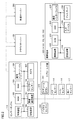
- FIG. 2 is a block diagram showing an outline of the configuration of the watching system 100.
- the sensor box 119 includes a control device 101, a ROM (Read Only Memory) 102, a RAM (Random Access Memory) 103, a communication interface 104, a camera 105, a Doppler sensor 106, a wireless communication device 107, and a storage device. It includes 108.
- the control device 101 controls the sensor box 119.
- the control device 101 is composed of, for example, at least one integrated circuit.
- the integrated circuit is, for example, at least one CPU (Central Processing Unit), MPU (Micro Processing Unit) or other processor, at least one ASIC (Application Specific Integrated Circuit), at least one FPGA (Field Programmable Gate Array), or these. It is composed of a combination of.
- An antenna (not shown) or the like is connected to the communication interface 104.
- the sensor box 119 exchanges data with an external communication device via the antenna.
- External communication devices include, for example, a management server 200, mobile terminals 161, 162, 163, 164 and other terminals, an access point 140, a cloud server 150, and other communication terminals.
- the camera 105 is a near-infrared camera in one realization example.
- Near-infrared cameras include IR (Infrared) floodlights that project near-infrared light. By using a near-infrared camera, images showing the inside of the living rooms 110 and 120 can be taken even at night.
- the camera 105 is a surveillance camera that receives only visible light.
- a 3D sensor or a thermography camera may be used as the camera 105.
- the sensor box 119 and the camera 105 may be configured as a single unit or as a combination of individual devices.
- the Doppler sensor 106 functions as a body motion sensor.
- the Doppler sensor 106 transmits and receives microwaves, ultrasonic waves, and other radio waves to detect the behavior (operation) of an object (for example, a resident 111, a care staff, etc.) in the living rooms 110 and 120.
- an object for example, a resident 111, a care staff, etc.
- the biometric information of the residents 111 and 121 of the living rooms 110 and 120 can be detected.
- the Doppler sensor 106 is connected to the control device 101 and measures the movement of the chest body surface accompanying the breathing of the resident 111 according to the control of the control device 101.
- the Doppler sensor 106 transmits microwaves and ultrasonic waves (hereinafter, also referred to as “transmitted waves”), receives microwaves and ultrasonic waves reflected by an object (that is, “reflected waves”), and transmits and reflected waves. Based on, the Doppler signal of the Doppler frequency component is output.
- the frequency of the reflected wave shifts in proportion to the moving speed of the object due to the so-called Doppler effect. Therefore, there is a difference (Doppler frequency component) between the frequency of the transmitted wave and the frequency of the reflected wave.
- the Doppler sensor 106 generates a signal of the Doppler frequency component as a Doppler signal at a predetermined sampling rate, and outputs the Doppler signal to the control device 101.
- the control device 101 receives the Doppler signal from the Doppler sensor 106, the control device 101 stores the received Doppler signal in the storage device 108 in chronological order.
- microwaves are used as transmitted waves, the microwaves pass through the clothes and are reflected on the body surface of the resident 111. Therefore, even if the resident 111 is wearing clothes, the movement of the body surface can be detected.
- each Doppler sensor 106 radiates microwaves in the 24 GHz band toward the beds 113 of the rooms 110 and 120, and receives the reflected waves reflected by the residents 111, 121 and the like.
- the reflected wave is Doppler-shifted by the movements of the residents 111 and 121.
- the Doppler sensor 106 can detect the respiratory state and heart rate of the residents 111 and 121 from the reflected wave.
- the wireless communication device 107 receives signals from the care call slave unit 115, the door sensor 118, the toilet sensor 116, the odor sensor 117, and the vital sensor 290, and transmits the signals to the control device 101.
- the care call slave unit 115 includes a care call button 241. When the care call button 241 is operated, the care call slave unit 115 transmits a signal (for example, a call signal) indicating that the operation has been performed. The transmitted signal is received by the wireless communication device 107. When the door sensor 118, the toilet sensor 116, the odor sensor 117, and the vital sensor 290 transmit their respective detection results, the transmitted signal is received by the wireless communication device 107.
- the storage device 108 is, for example, a fixed storage device such as a flash memory or a hard disk, or a recording medium such as an external storage device.
- the storage device 108 stores a program executed by the control device 101 and various data used for executing the program.
- Various data may include behavioral information of residents 111 and 121. Details of the behavior information will be described later.
- At least one of the above programs and data is a storage device accessible to the control device 101, a storage device other than the storage device 108 (for example, a storage area of the control device 101 (for example, a cache memory), ROM 102, etc.). It may be stored in the RAM 103, an external device (for example, a management server 200, a mobile terminal 161, 162, 163, 164, etc.).
- a storage device other than the storage device 108 for example, a storage area of the control device 101 (for example, a cache memory), ROM 102, etc.). It may be stored in the RAM 103, an external device (for example, a management server 200, a mobile terminal 161, 162, 163, 164, etc.).
- the action information is, for example, information indicating that the residents 111 and 121 have executed a predetermined action.
- the predetermined actions are "getting up” indicating that the residents 111 and 121 have awakened, “getting out” indicating that the residents 111 and 121 have left the bed (bedding) 113, and the residents 111 and 121. It includes four actions, “falling” indicating that the bed (bedding) 113 has fallen, and “falling” indicating that the residents 111 and 121 have fallen.
- the behavioral information may include actions taken by the resident to refuse to receive long-term care.
- the behavioral information may include an action of shaking off the caregiver by hand, an action of trying to kick the caregiver with a leg, an action of clinging to the bed 113 and refusing to change clothes, and the like.
- the control device 101 generates behavioral information for the occupants 111, 121 associated with the rooms 110, 120, based on images taken by the cameras 105 installed in the rooms 110, 120. do. For example, the control device 101 detects the heads of the occupants 111, 121 from the above image, and based on the time change of the size of the detected heads of the resident 111, 121, the resident 111, 121 " In addition to the usual information of "getting up”, “getting out of bed”, “falling” and “falling", the information of "refusal of long-term care" is detected.
- a specific example of generating behavioral information will be described in more detail.
- the storage device 108 stores the location area of each bed 113 in the living rooms 110 and 120, the first threshold value Th1, the second threshold value Th2, and the third threshold value Th3.
- the first threshold Th1 discriminates the size of the resident's head between the lying posture and the sitting posture in the location area of the bed 113.
- the second threshold Th2 identifies whether or not the resident is in a standing posture based on the size of the resident's head in the living rooms 110 and 120 excluding the area where the bed 113 is located.
- the third threshold Th3 identifies whether or not the resident is in the lying position based on the size of the resident's head in the living rooms 110 and 120 excluding the area where the bed 113 is located.
- the control device 101 extracts a moving object region from the target image as a region of the resident 111, 121 by, for example, a background subtraction method or a frame subtraction method.
- the control device 101 is further derived from the extracted moving body region by a neural network learned for head detection by pattern matching using a head model prepared in advance by, for example, a circular or elliptical Hough transform.
- the head regions of the residents 111 and 121 are extracted using the determined threshold.
- the control device 101 detects "getting up”, “getting out of bed”, “falling", and “falling" from the position and size of the extracted head.
- the position of the head extracted as described above is within the location region of the bed 113, and the size of the head extracted as described above is lying down by using the first threshold Th1.
- the control device 101 When the position of the head extracted as described above moves from the inside of the location area of the bed 113 to the outside of the location area of the bed 113, the control device 101 refers to the size of the head extracted as described above. By applying the second threshold value Th2, when it is detected that the head has changed from a certain size to a standing posture size, it may be determined that the action “getting out of bed” has occurred.
- the control device 101 When the position of the head extracted as described above moves from the inside of the location area of the bed 113 to the outside of the location area of the bed 113, the control device 101 refers to the size of the head extracted as described above.
- the third threshold value Th3 when it is detected that the head has changed from a certain size to the size of the lying posture, it may be determined that the behavior "fall" has occurred.
- the control device 101 uses the position of the head extracted as described above in the living rooms 110 and 120 excluding the area where the bed 113 is located, and the size of the extracted head uses the third threshold Th3. When it is detected that the size has changed from a certain size to the size of the lying posture, it may be determined that the behavior "fall" has occurred.
- control device 101 detects the caregiver in addition to the resident from the image data, and estimates the distance between the resident and the caregiver. If the control device presumes that the interval is shorter than a predetermined normal interval, it can determine that the long-term care refusal behavior is being performed. Further, when the control device 101 determines that the movement of the resident is different from the usual movement, it can be determined that the resident is showing the care refusal behavior to the caregiver.
- control device 101 of the sensor box 119 generates each action information of the residents 111 and 121.
- elements other than the control device 101 for example, the cloud server 150
- the control device 101 generate behavior information of the residents 111 and 121 using the images in the living rooms 110 and 120. May be good.
- the mobile terminal 220 includes a control device 221, a ROM 222, a RAM 223, a communication interface 224, a display 226, a storage device 228, and an input device 229.
- the mobile terminals 161, 162, 163, 164 are realized as, for example, smartphones, tablet terminals, wristwatch-type terminals, and other wearable devices.
- the control device 221 controls the mobile terminals 161, 162, 163, 164.
- the control device 221 is composed of, for example, at least one integrated circuit.
- An integrated circuit is composed of, for example, at least one CPU, at least one ASIC, at least one FPGA, or a combination thereof.
- An antenna (not shown) or the like is connected to the communication interface 224.
- the mobile terminals 161, 162, 163, and 164 exchange data with an external communication device via the antenna and the access point 140.
- External communication devices include, for example, a sensor box 119, a management server 200, and the like.
- the display 226 is realized by, for example, an organic EL (Electro Luminescence) display, a liquid crystal display, or the like.
- the input device 229 is realized by, for example, a touch sensor provided on the display 226. The touch sensor receives a touch operation on the mobile terminals 161, 162, 163, and 164, and outputs a signal corresponding to the touch operation to the control device 221.
- the storage device 228 is realized by, for example, a flash memory, a hard disk or other fixed storage device, a detachable data recording medium, or the like.
- the control device 101 identifies bed rest, lying down, getting up, getting out of bed, falling, falling, and microtremor abnormality, for example, as follows.
- the area in which the bed 113 is arranged (the area where the bed 113 is located) in the target image is stored in advance in the ROM 102 as one of various data.
- each threshold value and the continuation determination time are appropriately set from a plurality of samples and are stored in advance in the ROM 102 as one of various data.
- the control device 101 In the determination of entering the bed, the control device 101 has a person whose previous state variable (variable for storing the action determination result) is "getting out of bed” and is extracted from the target image acquired from the camera 105 this time by, for example, the background subtraction method.
- the area completely overlaps the location area of the bed 113 when the person area completely falls within the location area of the bed 113, it is tentatively determined to enter the floor, and the duration of the completely superimposed state is determined to continue entering the bed. If it continues for more than an hour, it is finally determined that there is a bed, and the bed is detected.
- the control device 101 updates the state variable as "entering the floor".
- the bed admission continuation determination time is used as a threshold value for finally determining the bed admission that is provisionally determined by the complete overlap between the extracted person area and the location area of the bed 113. ..
- Bed rest refers to a state in which a resident (monitored person) is lying on the bed 113.
- the control device 101 provides resident behavior information when the area occupied by the resident in the image is included in the area of the bed 113 and the movement amount of the resident is equal to or less than a predetermined amount. Detects "bed rest" as.
- the control device 101 determines that the previous state variable is "bed rest", and the area where the person area extracted from the target image acquired from the camera 105 this time protrudes from the location area of the bed 113 is wake-up determination. If it is equal to or more than the threshold value and less than the bed rest determination threshold value, it is tentatively determined to wake up. When the duration of the region in which the region is equal to or greater than the wake-up determination threshold value and is less than the wake-up determination threshold value exceeds the wake-up continuation determination time, the control device 101 finally determines that there is wake-up. Detects getting up. The control device 101 updates the state variable with "wake up".
- the wake-up determination threshold is used to determine whether or not the wake-up is caused by the size of the area.
- the bed leaving determination threshold value is used to determine whether or not the person has left the bed based on the size of the area.
- the wake-up determination threshold is set to a value larger than the wake-up determination threshold.
- the wake-up continuation determination time is used as a threshold value for finally determining wake-up, which is tentatively determined by comparing the area with the wake-up determination threshold value.
- the previous state variable was either "getting into bed” or “getting up”, and the person area extracted from the target image acquired from the camera 105 this time is the bed 113. If the area protruding from the location area is equal to or greater than the bed leaving determination threshold value, it is tentatively determined to be bed leaving. When the duration of the area in which the area is equal to or greater than the bed leaving determination threshold value exceeds the bed leaving continuation determination time, the control device 101 finally determines that the area has left the bed and detects the bed leaving. The control device 101 updates the state variable with "getting out of bed”. The bed leaving continuation determination time is used as a threshold value for finally determining that the bed leaving is tentatively determined by comparing the area with the bed leaving determination threshold value.
- the control device 101 has the size of the head region of the human region extracted from the target image acquired from the camera 105 this time equal to or less than the lying posture determination threshold value, and the change speed of the size of the head region. Is equal to or greater than the fall determination speed threshold value, and when the person area is within the fall determination area set around the location area of the bed 113, it is determined that there is a fall and the fall is detected.
- the lying posture determination threshold is used to determine whether or not it is the size of the head region in the lying posture. Whether it is in the lying position or the sitting position is determined based on the size of the head region.
- the fall determination speed threshold is used to determine whether or not there is a fall based on the rate of change in the size of the head region.
- the control device 101 has the size of the head region of the human region extracted from the target image acquired from the camera 105 this time equal to or less than the lying posture determination threshold value, and the change speed of the size of the head region. Is equal to or greater than the fall determination speed threshold value, and when the person area is in an area other than the location area of the bed 113 and the fall determination area, it is determined that there is a fall and a fall is detected.
- the fall determination speed threshold is used to determine whether or not a fall has occurred based on the rate of change in the size of the head region.
- the microdynamic abnormality is detected based on the Doppler signal output from the Doppler sensor 106. More specifically, the control device 101 performs, for example, a fast Fourier transform (FFT) on the Doppler signal measured within a predetermined time from the measurement time point to the past, and from the spectrum obtained by this FFT, it is general. Find the average value of the amplitude in the frequency band corresponding to the frequency of breathing. The control device 101 compares the obtained average value with a threshold value for determining whether or not the body movement is abnormal, and if the obtained average value is equal to or less than the threshold value, it is provisionally regarded as a microbody movement abnormality.
- FFT fast Fourier transform
- microtremor abnormality If the duration of the state in which the average value is equal to or less than the threshold value continues beyond the predetermined determination time, it is finally determined that there is a microtremor abnormality, and the microtremor abnormality is determined. Is detected.
- the control device 101 updates the state variable with "microbody movement abnormality".
- the determination time is used as a threshold value for finally determining the microbody movement abnormality tentatively determined by comparing the obtained average value with the microbody movement abnormality determination threshold value.
- the control device 101 When the control device 101 detects the predetermined behavior from the behavior of the resident in this way, the control device 101 transmits an event notification signal including event information representing the content of a predetermined event related to the resident from the communication interface 104 on the management server. Send to 200. More specifically, the control device 101 outputs an event notification signal including a sensor ID of the sensor box 119, event information indicating the content of the event, and a target image used when detecting wake-up, wake-up, wake-up, fall, and fall. , Transmit to the management server-200 via the communication interface 104.
- Event information includes one or more of bed rest, lying down, getting up, getting out of bed, falling, falling, microtremor abnormalities and care calls.
- the control device 101 accommodates one or more of the detected wake-up, wake-up, wake-up, fall, fall, and micro-movement abnormality in the event notification signal as event information.
- the image may include at least one of a still image and a moving image.
- a still image is first transmitted from the sensor box 119 to the management server 200, and the video is delivered at the request of the user (eg, caregiver, manager, doctor or other staff), as described below. Can be done.
- the moving image may be delivered first.
- the still image and the moving image are transmitted to the management server 200, and the mobile terminal 220 may display the still image or the moving image on the display 226 in a split screen state based on the signal sent from the management server 200. ..
- the control device 101 transmits an event notification signal including that fact as another example of a predetermined event to the management server 200, and uses a speaker (not shown) or the like. , Make a voice call with the mobile terminal 220. More specifically, when the care call button 241 is operated, a signal corresponding to the operation is received by the wireless communication device 107.
- the sensor box 119 generates an event notification signal including a nurse call as its sensor ID and event information, and transmits the event notification signal to the management server-200 via the communication interface 104.
- the control device 101 makes a voice call between the microphone (not shown) and the speaker (not shown) of the care call slave unit 115 and the mobile terminal 220 via a wireless communication device 107, for example, by VoIP (Voice over Internet Protocol). To realize.
- VoIP Voice over Internet Protocol
- control device 101 When the control device 101 receives a request for video distribution from an image display device such as a management server 200, a cloud server 150, or a mobile terminal 220 via the communication interface 104, the control device 101 responds to the request and takes a picture of the camera 105. (For example, a live video) is streamed and played back, and the video is distributed to the image display device.
- an image display device such as a management server 200, a cloud server 150, or a mobile terminal 220 via the communication interface 104
- the control device 101 responds to the request and takes a picture of the camera 105. (For example, a live video) is streamed and played back, and the video is distributed to the image display device.
- a live video For example, a live video
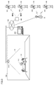
- FIG. 3 is a diagram showing an outline of the monitoring system 100 using the sensor box 119.
- the watching system 100 is used to watch over the residents 111, 121 and other residents who are the monitoring targets (monitoring targets).
- a sensor box 119 is attached to the ceiling of the living room 110. Sensor boxes 119 are similarly attached to other living rooms.
- the range 31 represents the detection range by the sensor box 119.
- the Doppler sensor detects the behavior of a person occurring within the range 31.
- the sensor box 119 has a camera as a sensor, the camera captures an image within range 31.
- the sensor box 119 is installed in, for example, a nursing care facility, a medical facility, or a home. In the example of FIG. 3, the sensor box 119 is mounted on the ceiling, and the resident 111 and the bed 113 are photographed from the ceiling.
- the mounting location of the sensor box 119 is not limited to the ceiling, and the sensor box 119 may be mounted on the side wall of the living room 110.
- the watching system 100 detects the danger occurring in the resident 111 based on a series of images (that is, images) obtained from the camera 105.
- the detectable danger includes a fall of the resident 111, a state where the resident 111 is present at a dangerous place (for example, a bed fence), and the like.
- the watching system 100 When the watching system 100 detects that the resident 111 is in danger, it notifies the caregivers 141, 142 and the like. As an example of the notification method, the monitoring system 100 notifies the mobile terminals 161, 162 of the caregivers 141 and 142 of the danger of the resident 111. Upon receiving the notification, the mobile terminals 161, 162 notify the caregiver 141, 142 of the danger of the resident 111 by a message, voice, vibration, or the like. As a result, the caregivers 141 and 142 can immediately grasp that the resident 111 is in danger and can quickly rush to the resident 111.
- the monitoring system 100 can also notify the mobile terminals 163 and 164 of the caregivers 143 and 144 outside the facility via the radio base station 15.
- FIG. 3 shows an example in which the watching system 100 includes one sensor box 119, but in other aspects, the watching system 100 may include a plurality of sensor boxes 119. Further, FIG. 3 shows an example in which the watching system 100 includes a plurality of mobile terminals 161, 162, but in another aspect, the watching system 100 can be realized by one mobile terminal.
- FIG. 4 is a block diagram showing a hardware configuration of the computer system 400.
- the computer system 400 functions as a gateway server 130, a cloud server 150, a push server 160, or a management server 200.
- the computer system 400 has, as main components, a CPU 1 that executes a program, a mouse 2 and a keyboard 3 that receive an instruction input by a user of the computer system 400, data generated by executing the program by the CPU 1, or a mouse 2.
- the RAM 4 that volatilely stores the data input via the keyboard 3, the hard disk 5 that stores the data non-volatilely, the optical disk drive device 6, the communication interface (I / F) 7, and the monitor 8 are used.
- the components are connected to each other by a data bus.
- a CD-ROM9 or other optical disc is mounted on the optical disc drive device 6.
- the processing in the computer system 400 is realized by each hardware and software executed by the CPU 1.
- Such software may be stored in the hard disk 5 in advance. Further, the software may be stored in a CD-ROM9 or other recording medium and distributed as a computer program. Alternatively, the software may be provided as an application program that can be downloaded by an information provider connected to the so-called Internet.
- Such software is temporarily stored in the hard disk 5 after being read from the recording medium by the optical disk driving device 6 or other reading device or downloaded via the communication interface 7.
- the software is read from the hard disk 5 by the CPU 1 and stored in the RAM 4 in the form of an executable program.
- the CPU 1 executes the program.
- Each component constituting the computer system 400 shown in FIG. 4 is a general one. Therefore, it can be said that one of the essential parts of the technical idea according to the present disclosure is software stored in RAM 4, hard disk 5, CD-ROM 9, or other recording medium, or software that can be downloaded via a network.
- the recording medium may include a non-temporary, computer-readable data recording medium. Since the operation of each hardware of the computer system 400 is well known, the detailed description will not be repeated.
- the recording medium is not limited to CD-ROM, FD (Flexible Disk), and hard disk, but also magnetic tape, cassette tape, and optical disc (MO (Magnetic Optical Disc) / MD (Mini Disc) / DVD (Digital Versatile Disc)).
- IC Integrated Circuit
- card including memory card
- optical card mask ROM
- EPROM Electrically Programmable Read-Only Memory
- EEPROM Electrically Erasable Programmable Read-Only Memory
- fixed semiconductor memory such as flash ROM, etc. It may be a medium that specifically carries the program.
- the program referred to here includes not only a program that can be directly executed by the CPU, but also a source program format program, a compressed program, an encrypted program, and the like.
- FIG. 5 is a diagram conceptually representing one aspect of data on the hard disk 5.
- the hard disk 5 holds tables 510 and 520.
- the hard disk 5 is included in the cloud server 150, the management server 200, and the like.
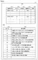
- Table 510 includes areas 511-515. Region 511 holds the date of observation. Area 512 holds identification information (ADL ID) of activities of daily living. Region 513 holds the measured values of the activities of daily living. Region 514 holds the observer ID. Area 515 holds text information, image information, voice information, and other information input by an observer or the like as remarks. Table 510 is created for each care recipient.
- ADL ID identification information
- Region 513 holds the measured values of the activities of daily living.
- Region 514 holds the observer ID.
- Area 515 holds text information, image information, voice information, and other information input by an observer or the like as remarks. Table 510 is created for each care recipient.
- Table 520 includes areas 521 and 522.
- Area 521 holds identification information (ADL ID) of activities of daily living.
- Region 522 holds an item of activities of daily living (also referred to as a "display index").
- the data shown in FIG. 5 includes, for example, measurement data acquired by the sensor box 119.
- the measurement data is sent from the sensor box 119 to the cloud server 150 for each care recipient at preset time intervals.
- the measurement data is stored in the hard disk 5 of the cloud server 150 or the management server 200. In another aspect, the measurement data may be stored in the mobile terminal 220.
- FIG. 6 is a diagram conceptually showing one aspect of storing data related to rehabilitation records for each care recipient.
- the hard disk 5 is included in the cloud server 150, the management server 200, and the like.
- the hard disk 5 holds the table 610.
- Table 610 includes regions 611, 612, 613, 614, 615, 616.
- Area 611 holds the date on which the rehabilitation took place.
- Area 612 holds the identification information ID of the rehabilitated care recipient.
- Area 613 holds the time during which the rehabilitation was performed.
- Area 614 holds information that identifies the person in charge of rehabilitation.
- Area 615 holds a rehabilitation menu.
- Region 616 holds the events observed during the rehabilitation and entered by the rehabilitation officer identified in Region 614.
- the data shown in FIG. 6 is input from the mobile terminal 220 by, for example, the staff in charge of rehabilitation of the care recipient.
- the staff selects a rehabilitation menu from the screen displayed on the mobile terminal 220, and records the ID (name or number) of the care recipient who received the rehabilitation, the time when the rehabilitation was performed, and the observation record. input.
- the mobile terminal 220 includes the date and time when the rehabilitation was performed, the care recipient ID, the staff identification data (person in charge ID), the time when the rehabilitation was performed, the person in charge ID, the rehabilitation menu, and the observation.
- the record is transmitted to the cloud server 150.
- the CPU 1 of the cloud server 150 sequentially stores these data in the hard disk 5 (areas 611 to 616).
- FIG. 7 is a flowchart showing a part of the processing executed by the CPU 1 of the management server 200.
- step S710 the CPU 1 accepts the selection of the display index (item) constituting the activities of daily living (ADL).
- the monitor 8 of the management server 200 displays a screen (FIG. 8) described later.
- the care staff selects the item to be displayed from the screen by touch operation, mouse operation, voice input or other operations.
- step S720 the CPU 1 accesses the database of the selected display index.
- the database is configured on the hard disk 5 as, for example, tables 510 and 520.
- step S730 the CPU 1 calculates the moving average of the display index data for the designated period.
- the period is, for example, one week, two weeks, one month, three months, six months, one year, and the like, but is not particularly limited.
- the period may be preset by the administrator or changed each time by the care staff.
- step S740 the CPU 1 calculates the rate of change of the moving average.
- the care staff can know the degree of change in activities of daily living by referring to the rate of change in the moving average.
- step S750 the CPU 1 accesses the database (table 610) and reads out the rehabilitation record.
- the CPU 1 reads out a record of rehabilitation performed on the care recipient during the period specified in step S730.
- the CPU 1 may read a record of rehabilitation performed during the same period for another care recipient to be compared. In this case, the CPU 1 reads out the rehabilitation record of the other long-term care person based on the input of the identification data of the long-term care person designated as the comparison target.
- step S760 the CPU 1 selects a rehabilitation menu according to the care recipient from a predetermined recommended menu list based on the rate of change and the rehabilitation record.
- the management server 200 holds a rehabilitation menu prepared in advance according to the degree of change in activities of daily living on the hard disk 5.
- the CPU 1 can select the rehabilitation menu to which the change rate corresponds from the hard disk 5 by using the change rate of the selected activities of daily living of the care recipient as a search key.
- the CPU 1 may read the contents of the rehabilitation performed on the other care recipient from the hard disk 5 and display it on the monitor 8 in a manner selectable by the care staff.
- step S770 the CPU 1 displays a graph including the display index data (the value actually measured or calculated for each monitoring item) and the moving average on the monitor 8. Since the care staff can see the moving average in addition to the data, it is possible to easily confirm the transition of the ADL state of the care recipient.
- step S780 the CPU 1 displays the rehabilitation record on the monitor 8.
- the rehabilitation record is associated with the date shown in the graph above. Therefore, the care staff can easily confirm what kind of rehabilitation has been performed in the past and how the ADL state has changed as a result by referring to the graph.
- step S790 the CPU 1 displays a rehabilitation menu corresponding to the care recipient on the monitor 8.
- the CPU 1 selects a recommended rehabilitation from a pre-prepared rehabilitation menu according to a change in the ADL state, and displays the selected rehabilitation on the monitor 8.
- the CPU 1 may display the content of rehabilitation performed on another care recipient who has shown a similar change in ADL state.
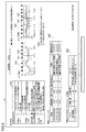
- FIG. 8 is a diagram showing an example of information related to activities of daily living displayed on the monitor 8.
- the monitor 8 displays tables 810, 840, 850 and screens 820, 830 for the designated care recipient.
- Table 810 accepts an input for selecting an activity of daily living to be displayed on the monitor 8 among a plurality of activities of daily living (step S710).
- the user selects a check box displayed on the monitor 8 by mouse operation, touch operation, or voice input, so that an activity of daily living associated with the check box is selected.
- two activities of daily living namely "walking speed” and "degree of wobbling", are selected so that two check boxes are specified.
- the screen 820 displays the information of the "walking speed" selected in the table 810. More specifically, the screen 820 displays the graphs 821 and 822.
- Graph 821 shows the transition of walking speed. In a certain aspect, the graph 821 shows the transition of the walking speed over a predetermined period. This period is set, for example, as a period that goes back a certain period from the date on which the information shown in FIG. 8 is extracted. The fixed period going back is, for example, one week, two weeks, one month, three months, etc., but the period is not limited to these, and the user can arbitrarily specify the display period.
- Graph 822 shows the change in the moving average of walking speed.
- the two symbols represent the date on which the rehabilitation was performed and the content of the rehabilitation, respectively. Since the graph displayed on the screen 820 and the rehabilitation are associated with each other by the symbol, the user can recognize the relationship between the transition of activities of daily living and the content of the rehabilitation.
- the screen 830 displays the information of the "stagger degree” selected in the table 810. More specifically, the screen 830 displays graphs 831 and 832.
- Graph 831 shows the transition of the degree of wobble. In a certain aspect, the graph 831 shows the transition of the degree of wobble over a predetermined period. Similar to the graphs 821 and 822 on the screen 820, this period is set as, for example, a period that goes back a certain period from the date when the information shown in FIG. 8 is extracted. This period may be the same as or different from the period displayed on the screen 820.
- Graph 832 shows the change in the moving average of the degree of wobble.
- Table 840 displays the contents of the rehabilitation performed. In one aspect, the table 840 displays the contents of the most recent rehabilitation. The period illustrated in Table 840 is 3 days, but the period displayed is not limited and may be displayed retroactively. In another aspect, the period displayed on the table 840 may be moved in conjunction with the change of the period on the screen 820 or the screen 830.
- the content of the rehabilitation performed during the period corresponding to the period specified on the screen 820 or 830 may be displayed. For example, when "September 8th to September 15th" is selected on the screen 820, the rehabilitation performed during the selected period may be displayed on the table 840. At this time, the period may be scrolled and displayed according to the size of the area reserved for displaying the table 840.
- Table 850 contains information on the rehabilitation menu recommended for the care recipient.
- table 850 includes a menu, a recommended number of times to implement the menu, activity time, and comments.
- the menu is determined based on the care recipient's current condition, the care recipient's wishes, and past changes in activities of daily living.
- the menu is determined by the caregiver in one aspect, or based on performance data by other caregivers who have seen similar conditions, wishes, and changes in past activities of daily living in other aspects. obtain.
- the graph showing changes in activities of daily living by the care recipient does not necessarily have to be a rising graph.
- FIG. 9 is a diagram showing measured values and moving averages of other activities of daily living.
- Graphs 910 and 930 represent measured values of activities of daily living.
- Graphs 920 and 940 represent moving averages of activities of daily living.
- another ADL status to be compared may be displayed.
- the comparison target past ADL states of a plurality of care recipients in the same state, changes in the average ADL state, and the like can be used.
- FIG. 10 is a diagram showing a state in which the ADL state to be compared is displayed in addition to the ADL state of the designated care recipient.
- the monitor 8 displays a graph 1010 showing the ADL state of the designated care recipient (for example, the care recipient currently resident in the facility) and a graph 1020 showing the ADL state to be compared.
- Graph 1020 may show the average or median value of each of the data for a particular care recipient or for a plurality of care recipients similarly classified.
- the manager or the care recipient's family can compare the ADL status of the care recipient with other ADL status, so that the state of change in the ADL status or the tendency of the care recipient to improve their activity ability can be easily improved. Can be grasped.
- the information indicating the ADL state of the care recipient and the change in the ADL state is displayed on the monitor 8, the display 226 and other display devices, so that the user can use the care recipient.
- the tendency of improvement can be judged objectively.
- a method is provided that is performed on a computer (a computer system 400 such as a cloud server 150 or a management server 200, a mobile terminal 220, etc.) to provide information about a care recipient.
- a computer a computer system 400 such as a cloud server 150 or a management server 200, a mobile terminal 220, etc.
- This method is performed, for example, by the CPU 1 or the control device 221.
- This method includes a step of accessing a plurality of motion data (for example, amount of activity, walking speed, degree of wobble, repetitive behavior) acquired by observing the activities of daily living of the care recipient multiple times, and a plurality of motion data.
- a step of displaying information indicating a change in the degree of activities of daily living for example, a graph of moving average
- the rehabilitation recommended for the care recipient is shown on the monitor 8 or the display 226.
- a computer user for example, an administrator or a care recipient's family
- the objectivity is ensured and the family of the care recipient can obtain a sense of security.
- the method further includes, in addition to the above configuration, a step of accepting selection of one or more activities of daily living from a plurality of activities of daily living.
- the selection is, for example, to mark a check box on the displayed screen.
- the step of displaying a plurality of motion data includes displaying motion data for one or more selected activities of daily living. According to this configuration, the situation of the care recipient can be confirmed for the activities of daily living selected from a plurality of activities of daily living.
- the step of displaying information includes displaying a graph showing a change (for example, a line graph, a bar graph, etc.).
- a change for example, a line graph, a bar graph, etc.
- one or more marks indicating that one or more rehabilitations have been performed by the care recipient are displayed on the monitor 8 or the display 226 in association with the date on which the rehabilitation was performed in the graph. Including further.
- the mark includes symbols or letters. According to such a configuration, the user of the computer system 400 can easily confirm when the rehabilitation was performed.
- the step of displaying one or more marks includes displaying a mark that identifies each of the plurality of rehabilitations performed on the care recipient. For example, different symbols or different colors with the same symbol are used as the mark. According to such a configuration, the user of the computer system 400 can easily confirm when a plurality of rehabilitations have been performed.
- the method of following a certain aspect further includes a step of displaying a comment indicating a change in activities of daily living in which a graph is displayed. According to such a configuration, even a person who does not have specialized knowledge, such as a family member of the care recipient, can confirm the situation of the care recipient by referring to the comment.
- the method according to a certain aspect further includes a step of accepting the designation of the day when any of a plurality of activities of daily living is performed.
- the step of displaying the contents of rehabilitation includes displaying the contents of rehabilitation performed on a specified day. According to such a configuration, for example, when the past data is stored for a long period of time, the user of the computer system 400 can quickly confirm the contents of the rehabilitation on a specific date or period.
- the method according to a certain aspect further includes a step of accepting an operation for changing a day designated as a day when any of a plurality of activities of daily living is performed.
- Displaying the content of rehabilitation includes displaying the content of rehabilitation performed on the day after the change in response to the operation of the change.
- the user can easily change the date to be displayed to another date by sliding and changing the date on the monitor 8 or the display 226 by a mouse operation or a touch operation.
- the contents of the rehabilitation performed on the changed date are displayed, so that the manager or the care staff or the family of the care recipient can see the past transition of the ADL state and the past transition of the ADL state at that time. It is possible to easily confirm the rehabilitation performed.
- the method according to a certain aspect further includes a step of displaying information indicating a change in the degree of activities of daily living based on a plurality of motion data acquired for other care recipients. According to such a configuration, information about other care recipients is displayed for comparison. Therefore, the manager, the care staff, or the care recipient's family can compare the transition of the ADL status of the care recipient with the transition of the ADL status of the other care recipient, and thus the ADL of the caregiver that day. It becomes easier to judge the state.
- a program causes one or more processors to execute a method for providing information on a care recipient.
- the program accesses one or more processors to access multiple motion data acquired by observing the activities of daily living of the care recipient multiple times, displays multiple motion data, and displays each motion data. Based on this, displaying information indicating changes in the degree of activities of daily living, displaying the contents of rehabilitation performed for the care recipient, the contents of rehabilitation, and changes in the degree of activities of daily living. To output the recommended rehabilitation to the care recipient based on the above.
- a program that follows a certain aspect further causes one or more processors to accept a selection of one or more activities of daily living from a plurality of activities of daily living.
- Displaying a plurality of motion data includes displaying motion data for one or more selected activities of daily living.
- displaying information includes displaying a graph showing changes.
- the program will display on one or more processors one or more marks indicating that one or more rehabilitations have been performed by the care recipient, in association with the date of the rehabilitation in the graph. Let it run further.
- a program that follows a certain aspect causes one or more processors to further execute a comment indicating a change in activities of daily living on which a graph is displayed.
- a program that follows a certain aspect further causes one or more processors to accept the designation of the day when any of a plurality of activities of daily living is performed. Displaying the contents of rehabilitation includes displaying the contents of rehabilitation performed on a designated day.
- a program further executes information indicating a change in the degree of activities of daily living on one or more processors based on a plurality of motion data acquired for other care recipients. Let me.
- an information providing device includes a memory for storing an instruction and a processor for executing the instruction.
- the instruction accesses the processor to access multiple movement data acquired by observing the care recipient's activities of daily living multiple times, and displays multiple movement data.
- Displaying information indicating changes in the degree of activities of daily living based on each movement data displaying the contents of rehabilitation performed for the care recipient, the contents of rehabilitation, and activities of daily living To output the recommended rehabilitation to the care recipient based on the change in the degree of.
- an instruction further causes a processor to accept a selection of one or more activities of daily living from a plurality of activities of daily living.
- Displaying a plurality of motion data includes displaying motion data for one or more selected activities of daily living.
- Displaying information in an information providing device includes displaying a graph showing a change.
- the instruction further causes the processor to display one or more marks in the graph indicating that one or more rehabilitations have been performed by the care recipient, in association with the date on which the rehabilitation was performed.
- the instruction further causes the processor to display a comment indicating a change in activities of daily living on which a graph is displayed.
- an instruction further causes a processor to accept a designation of a day when any of a plurality of activities of daily living is performed. Displaying the contents of rehabilitation includes displaying the contents of rehabilitation performed on a designated day.
- an instruction further indicates that the processor displays information indicating a change in the degree of activities of daily living based on a plurality of motion data acquired for other care recipients. Let it run.
- This disclosure is applicable to computers used in facilities where information on activities of daily living (ADL) is required.
Landscapes
- Health & Medical Sciences (AREA)
- Engineering & Computer Science (AREA)
- Medical Informatics (AREA)
- Biomedical Technology (AREA)
- Pathology (AREA)
- Epidemiology (AREA)
- General Health & Medical Sciences (AREA)
- Primary Health Care (AREA)
- Public Health (AREA)
- Alarm Systems (AREA)
Abstract
被介護者の日常生活動作(ADL)の状態を「見える化」する技術が提供される。プロセッサーが実行する処理は、日常生活動作を構成する項目の選択を受け付けるステップ(S710)と、当該項目のデータベースにアクセスするステップ(S720)と、指定された期間について項目のデータの移動平均を算出するステップ(S730)と、移動平均の変化率を算出するステップ(S740)と、データベースにアクセスしてリハビリテーション記録を読み出すステップ(S750)と、変化率とリハビリテーション記録に基づいて当該被介護者に応じたリハビリテーションメニューを選択するステップ(S760)と、項目のデータと移動平均とを含むグラフを表示するステップ(S770)と、リハビリテーション記録を表示するステップ(S780)と、当該被介護者に応じたリハビリテーションメニューを表示するステップ(S790)とを含む。
Description
本開示は、概して情報の提示に関し、より特定的には、日常生活動作に関する情報の提示に関する。
人の日常生活動作(ADL)に関し、例えば、特表2018-507008号公報(特許文献1)は、「環境内の人の日常生活動作、ADLをモニタリングするためのシステムと方法」を開示している。特許文献1に開示された技術によると、「システムは人と環境のうち少なくとも一方の特性の検出値をあらわすセンサ出力信号を受信し、人の推論ADLをあらわす推論ADL出力信号を生成するように適応されるADL推論ユニットを有する。モニタユニットは受信センサ出力信号と推論ADL出力信号のうち少なくとも一つに依存するモニタ信号を生成するように適応される。」というものである([要約]参照)。
例えば、介護施設に入居している被介護者(適宜「入居者」ともいう)の日常生活動作については、被介護者本人よりも、当該被介護者の家族あるいは介護スタッフが、本人の状態を把握するために、日常生活動作の状態を知りたい場合がある。したがって、日常生活動作の状態を客観的に表示する技術が必要とされている。
本開示は上述のような背景に鑑みてなされたものであって、ある局面に従うと、日常生活動作の状態を客観的に表示する技術が開示される。
ある実施の形態に従うと、被介護者の情報を提供するためにコンピューターで実行される方法が提供される。この方法は、被介護者の日常生活動作を複数回観察することにより取得された複数の動作データにアクセスすることと、複数の動作データを表示することと、各動作データに基づいて、日常生活動作の程度の変化を表わす情報を表示することと、被介護者に対して実施されたリハビリテーションの内容を表示することと、リハビリテーションの内容と、日常生活動作の程度の変化とに基づいて、当該被介護者に推奨されるリハビリテーションを出力することとを含む。
ある局面に従う方法は、複数の日常生活動作から1以上の日常生活動作の選択を受け付けることをさらに含む。複数の動作データを表示することは、選択された1以上の日常生活動作についての動作データを表示することを含む。
ある局面に従う方法において、情報を表示することは、変化を表わすグラフを表示することを含む。上記方法は、当該被介護者による1以上のリハビリテーションが行なわれたことを表わす1つ以上の印を、グラフの中における当該リハビリテーションが行なわれた日に関連付けて表示することをさらに含む。
ある局面に従う方法において、1つ以上の印を表示することは、当該被介護者に対して実施された複数のリハビリテーションの各々を識別する印を表示することを含む。
ある局面に従う方法は、グラフが表示された日常生活動作についての変化を表わすコメントを表示することをさらに含む。
ある局面に従う方法は、複数の日常生活動作のいずれかが行なわれた日の指定を受け付けることをさらに含む。リハビリテーションの内容を表示することは、指定された日に行なわれたリハビリテーションの内容を表示することを含む。
ある局面に従う方法は、複数の日常生活動作のいずれかが行なわれた日として指定された日を変更するための操作を受け付けることをさらに含む。リハビリテーションの内容を表示することは、変更の操作に応じて、変更後の日に行なわれたリハビリテーションの内容を表示することを含む。
ある局面に従う方法は、他の被介護者について取得された複数の動作データに基づいて、日常生活動作の程度の変化を表わす情報を表示することをさらに含む。
他の実施の形態に従うと、上記のいずれかに記載の方法を1つ以上のプロセッサーに実行させるプログラムが提供される。
さらに他の実施の形態に従うと、上記のプログラムと、当該プログラムを実行するプロセッサーとを備える、情報提供装置が提供される。
ある局面において、日常生活動作の状態が客観的に表示される。
この発明の上記および他の目的、特徴、局面および利点は、添付の図面と関連して理解されるこの発明に関する次の詳細な説明から明らかとなるであろう。
この発明の上記および他の目的、特徴、局面および利点は、添付の図面と関連して理解されるこの発明に関する次の詳細な説明から明らかとなるであろう。
以下、図面を参照しつつ、本発明の実施の形態について説明する。以下の説明では、同一の部品には同一の符号を付してある。それらの名称および機能も同じである。したがって、それらについての詳細な説明は繰り返さない。
<システムの概要>
図1を参照して、ADLに関する情報を取得可能な見守りシステムの概要について説明する。図1は、見守りシステム100の構成の一例を示す図である。見守り対象の一例は、施設180の居室領域に設けられた各居室内の入居者である。図1の見守りシステム100では、居室領域に、居室110,120が設けられている。居室110は、入居者111に割り当てられている。居室120は、入居者121に割り当てられている。
図1を参照して、ADLに関する情報を取得可能な見守りシステムの概要について説明する。図1は、見守りシステム100の構成の一例を示す図である。見守り対象の一例は、施設180の居室領域に設けられた各居室内の入居者である。図1の見守りシステム100では、居室領域に、居室110,120が設けられている。居室110は、入居者111に割り当てられている。居室120は、入居者121に割り当てられている。
見守りシステム100は、ゲートウェイサーバー130と、交換装置12と、アクセスポイント140と、管理サーバー200と、センサーボックス119と、センサーボックス119と通信する各種機器と、携帯端末161,162,163,164とを含む。
ゲートウェイサーバー130は、施設180の内部ネットワーク(イントラネット)と、施設180の外部ネットワーク16とを互いに接続する。外部ネットワーク16は、たとえば、インターネットや公衆電話回線網である。また、外部ネットワーク16には、クラウドサーバー150と、プッシュサーバー160と、無線基地局15とが接続されている。
交換装置135は、施設180の内部ネットワークの各機器を互いに接続する。ある局面において、ルーターやスイッチが交換装置135として使用されてもよい。図1に示される例では、交換装置135の数は2であるが、当該数はこれに限定されない。施設180の内部ネットワークは、複数の交換装置135の組み合わせによって構成されてもよい。
アクセスポイント140は、携帯端末161,162を施設180の内部ネットワークに接続するために使用される。ある局面において、Wi-Fi(登録商標)(Wireless Fidelity)ルーターが、アクセスポイント140として使用され得る。
管理サーバー200は、施設180の中のセンサーボックス119からイベント情報を受信し、各居室の入居者の情報を管理する。また、管理サーバー200は、携帯端末161,162とも通信し、当該携帯端末を保持するスタッフを管理すると共に、各携帯端末に各種の通知を送信する。なお、管理サーバー200は、携帯端末161,162に通知を送信する場合、外部のプッシュサーバー160を使用してもよい。また、外部のクラウドサーバー150が、管理サーバー200の一部または全ての機能を備えていてもよい。
センサーボックス119は、その筐体に内蔵されたカメラおよびセンサーと、居室110,120内の他の各種センサーと連携することにより、居室110,120内の入居者111,121に関する情報をそれぞれ取得する。当該情報は、各入居者の歩行を示す画像、体温や脈拍その他のバイタル情報等を含み得る。また、センサーボックス119は、内部ネットワークを介して、管理サーバー200に、取得した入居者111,121に関する情報を送信する。センサーボックス119の詳細は後述する。
携帯端末161,162は、施設180で介護に従事する介護者その他のスタッフにより使用される。スタッフは、携帯端末161,162を用いて、介護記録等を入力できる。携帯端末161,162は、当該介護記録を管理サーバー200に送信する。また、入居者111,121に問題が発生した場合には、スタッフは、携帯端末161,162を用いて、管理サーバー200から通知を受信する。携帯端末161,162は、施設180の中ではアクセスポイント140と接続され、内部ネットワークを介して管理サーバー200と通信する。本明細書の例では、介護者141,142,143,144がそれぞれ携帯端末161,162,163,164を保持している。
携帯端末163,164は、施設180の外からは、無線基地局15等を介して、ゲートウェイサーバー11を経由して管理サーバー200と通信することができる。携帯端末163,164が施設180の外から管理サーバー200と通信する場合、管理サーバー200から携帯端末163,164に提供されるサービスの一部は、入居者の情報を保護するために制限される場合がある。
なお、携帯端末161,162、アクセスポイント140、交換装置135等の他の装置の数は、図1に例示される数に限定されない。
居室110,120は、それぞれ、設備として、家具112、ベッド113、および、トイレ114を含む。居室110,120のドアには、当該ドアの開閉を検出するドアセンサー118がそれぞれ設置されている。トイレ114のドアには、トイレ114の開閉を検出するトイレセンサー116が設置されている。ベッド113には、入居者111の排泄情報を取得する臭いセンサー117が設置されている。入居者111は、当該入居者111のバイタル情報を検出するバイタルセンサー290を装着している。検出されるバイタル情報の一例は、入居者の体温である。他の例は、入居者の呼吸である。さらに他の例は、入居者の心拍数である。さらに他の例は、これらの情報の中の2以上の種類の情報である。居室110では、入居者111はケアコール子機115を操作することができる。入居者111がケアコール子機115を操作すると、ケアコール子機115は、呼び出し信号を発信し、呼び出し信号は、センサーボックス119により受信される。センサーボックス119は、その受信した呼び出し信号を管理サーバー200に送信する。管理サーバー200は、入居者111から呼び出しを受けていることを通知する信号を携帯端末220に送信する。
センサーボックス119は、居室110,120内の物体の挙動を検出するためのセンサーを内蔵する。センサーの一例は、物体の動作を検出するためのドップラーセンサーである。他の例は、カメラである。さらに他の例は、ケアコール子機115、ドアセンサー118、トイレセンサー116、臭いセンサー117、または、バイタルセンサー290である。センサーボックス119は、センサーとして、これらのセンサー中の少なくとも一つを含み得る。
図2を参照して、見守りシステム100の構成要素について説明する。図2は、見守りシステム100の構成の概要を示すブロック図である。
[センサーボックス119]
センサーボックス119は、制御装置101と、ROM(Read Only Memory)102と、RAM(Random Access Memory)103と、通信インターフェイス104と、カメラ105と、ドップラーセンサー106と、無線通信装置107と、記憶装置108とを備える。
センサーボックス119は、制御装置101と、ROM(Read Only Memory)102と、RAM(Random Access Memory)103と、通信インターフェイス104と、カメラ105と、ドップラーセンサー106と、無線通信装置107と、記憶装置108とを備える。
制御装置101は、センサーボックス119を制御する。制御装置101は、たとえば、少なくとも1つの集積回路によって構成される。集積回路は、たとえば、少なくとも1つのCPU(Central Processing Unit)、MPU(Micro Processing Unit)その他のプロセッサー、少なくとも1つのASIC(Application Specific Integrated Circuit)、少なくとも1つのFPGA(Field Programmable Gate Array)、またはこれらの組み合わせなどによって構成される。
通信インターフェイス104には、アンテナ(図示しない)などが接続される。センサーボックス119は、当該アンテナを介して、外部の通信機器との間でデータをやり取りする。外部の通信機器は、たとえば、管理サーバー200、携帯端末161,162,163,164その他の端末、アクセスポイント140、クラウドサーバー150、その他の通信端末などを含む。
カメラ105は、一実現例では、近赤外カメラである。近赤外カメラは、近赤外光を投光するIR(Infrared)投光器を含む。近赤外カメラが用いられることにより、夜間でも居室110,120の内部を表わす画像が撮影され得る。他の実現例では、カメラ105は、可視光のみを受光する監視カメラである。さらに他の実現例では、カメラ105として、3Dセンサやサーモグラフィーカメラが用いられてもよい。センサーボックス119およびカメラ105は、一体として構成されてもよいし、個別の装置の組み合わせとして構成されてもよい。
ドップラーセンサー106は、体動センサーとして機能する。ドップラーセンサー106は、マイクロ波、超音波その他の電波を発信及び受信して、居室110,120内の物体(例えば入居者111や介護スタッフ等)の挙動(動作)を検出する。これにより、居室110,120の入居者111,121の生体情報が検出され得る。
より具体的には、ドップラーセンサー106は、制御装置101に接続され、制御装置101の制御に従って、入居者111の呼吸に伴う胸部の体表の動きを測定する。ドップラーセンサー106は、マイクロ波や超音波を送信し(以下「送信波」ともいう。)、物体で反射されたマイクロ波や超音波(すなわち「反射波」)を受信し、送信波と反射波とに基づいて、ドップラー周波数成分のドップラー信号を出力する。物体が動いている場合、反射波の周波数が所謂ドップラー効果により当該物体の動いている速度に比例してシフトする。そのため、送信波の周波数と反射波の周波数とに差(ドップラー周波数成分)が生じる。ドップラーセンサー106は、このドップラー周波数成分の信号をドップラー信号として所定のサンプリングレートで生成し、制御装置101に当該ドップラー信号を出力する。制御装置101は、ドップラーセンサー106からドップラー信号を受信すると、この受信したドップラー信号を時系列に記憶装置108に格納する。なお、マイクロ波が送信波として使用されると、当該マイクロ波は、着衣を透過して入居者111の体表で反射する。そのため、入居者111が衣服を着ていても体表の動きを検知できる。
一例では、各ドップラーセンサー106は、24GHz帯のマイクロ波を各居室110,120のベッド113に向けて放射し、入居者111,121等で反射した反射波を受信する。反射波は、入居者111,121の動作により、ドップラーシフトしている。ドップラーセンサー106は、当該反射波から、入居者111,121の呼吸状態や心拍数を検出し得る。
無線通信装置107は、ケアコール子機115、ドアセンサー118、トイレセンサー116、臭いセンサー117、および、バイタルセンサー290からの信号を受信し、当該信号を制御装置101へ送信する。ケアコール子機115は、ケアコールボタン241を備える。ケアコールボタン241が操作されると、ケアコール子機115は、当該操作があったことを示す信号(例えば呼び出し信号)を発信する。発信された信号は、無線通信装置107によって受信される。ドアセンサー118、トイレセンサー116、臭いセンサー117、および、バイタルセンサー290は、それぞれの検出結果を送信すると、送信された信号は、無線通信装置107によって受信される。
記憶装置108は、たとえば、フラッシュメモリーまたはハードディスク等の固定記憶装置、あるいは、外付けの記憶装置などの記録媒体である。記憶装置108は、制御装置101によって実行されるプログラム、および、当該プログラムの実行に利用される各種のデータを格納する。各種のデータは、入居者111,121の行動情報を含んでいてもよい。行動情報の詳細は後述する。
上記のプログラムおよびデータのうち少なくとも一方は、制御装置101がアクセス可能な記憶装置であれば、記憶装置108以外の記憶装置(たとえば、制御装置101の記憶領域(たとえば、キャッシュメモリーなど)、ROM102、RAM103、外部機器(たとえば、管理サーバー200や携帯端末161,162,163,164等)に格納されていてもよい。
[行動情報]
次に、本実施の形態における行動情報について、説明する。行動情報は、たとえば入居者111,121が所定の行動を実行したことを表わす情報である。一例では、所定の行動は、入居者111,121が起きたことを表わす「起床」、入居者111,121がベッド(寝具)113から離れたことを表わす「離床」、入居者111,121がベッド(寝具)113から落ちたことを表わす「転落」、および、入居者111,121が倒れたことを表わす「転倒」の4つの行動を含む。
次に、本実施の形態における行動情報について、説明する。行動情報は、たとえば入居者111,121が所定の行動を実行したことを表わす情報である。一例では、所定の行動は、入居者111,121が起きたことを表わす「起床」、入居者111,121がベッド(寝具)113から離れたことを表わす「離床」、入居者111,121がベッド(寝具)113から落ちたことを表わす「転落」、および、入居者111,121が倒れたことを表わす「転倒」の4つの行動を含む。
さらに、行動情報は、入居者が介護を受けることを拒否するために行なう動作を含み得る。例えば、行動情報は、手で介護者を振り払う動作、脚で介護者を蹴ろうとする動作、ベッド113にしがみついて着替えを拒否する動作等を含み得る。
ある実施の形態では、制御装置101が、各居室110,120に設置されたカメラ105が撮像した画像に基づいて、各居室110,120に関連付けられた入居者111,121の各行動情報を生成する。制御装置101は、たとえば、上記画像から入居者111,121の頭部を検出し、この検出した入居者111,121の頭部における大きさの時間変化に基づいて、入居者111,121の「起床」、「離床」、「転倒」および「転落」の通常の情報に加えて、「介護拒否」という情報を検出する。以下、行動情報の生成の一具体例を、より詳細に説明する。
まず、記憶装置108に、居室110,120における各ベッド113の所在領域、第1閾値Th1、第2閾値Th2、および、第3閾値Th3が格納される。第1閾値Th1は、ベッド113の所在領域内において、横臥姿勢にあるときと座位姿勢にあるときとの間で入居者の頭部の大きさを識別する。第2閾値Th2は、ベッド113の所在領域を除く居室110,120内において、入居者の頭部の大きさに基づいて、当該入居者が立位姿勢にあるか否かを識別する。第3閾値Th3は、ベッド113の所在領域を除く居室110,120内において、入居者の頭部の大きさに基づいて、当該入居者が横臥姿勢にあるか否かを識別する。
制御装置101は、対象画像から、例えば背景差分法やフレーム差分法によって、入居者111,121の人物の領域として、動体領域を抽出する。制御装置101は、さらに、当該抽出した動体領域から、例えば円形や楕円形のハフ変換によって、予め用意された頭部のモデルを用いたパターンマッチングによって、頭部検出用に学習したニューラルネットワークによって導出された閾値を用いて、入居者111,121の頭部領域を抽出する。制御装置101は、当該抽出された頭部の位置および大きさから、「起床」、「離床」、「転倒」および「転落」を検知する。
制御装置101は、上記のように抽出された頭部の位置がベッド113の所在領域内にあり、かつ、上記のように抽出された頭部の大きさが第1閾値Th1を用いることによって横臥姿勢の大きさから座位姿勢の大きさへと変化したことを検出した場合に、行動「起床」が発生したことを決定してもよい。
制御装置101は、上記のように抽出された頭部の位置がベッド113の所在領域内からベッド113の所在領域外へ移動した場合において、上記のように抽出された頭部の大きさに対して第2閾値Th2を適用することにより、頭部がある大きさから立位姿勢の大きさへと変化したことを検出したときには、行動「離床」が発生したと判定してもよい。
制御装置101は、上記のように抽出された頭部の位置がベッド113の所在領域内からベッド113の所在領域外へ移動した場合において、上記のように抽出された頭部の大きさに対して第3閾値Th3を適用することにより、頭部がある大きさから横臥姿勢の大きさへと変化したことを検出したときには、行動「転落」が発生したと判定してもよい。
制御装置101は、上記のように抽出された頭部の位置がベッド113の所在領域を除く居室110,120内に位置し、かつ、抽出された頭部の大きさが第3閾値Th3を用いることによって或る大きさから横臥姿勢の大きさへと変化したことを検出した場合には、行動「転倒」が発生したと決定してもよい。
さらに、制御装置101は、画像データから入居者に加えて介護者を検出し、入居者と介護者との間隔を推定する。制御装置は、当該間隔が予め定められた通常の間隔よりも短いと推定すると、介護拒否行動が行なわれていると判断し得る。さらに、制御装置101は、入居者の動作が通常と違う動きを示していると判断すると、当該入居者は介護者に対して、介護拒否行動を示していると判断し得る。
以上のようにして、一具体例では、センサーボックス119の制御装置101が、入居者111,121の各行動情報を生成する。なお、他の局面に従う見守りシステム100では、居室110,120内の画像を用いて、制御装置101以外の他の要素(例えば、クラウドサーバー150)が入居者111,121の行動情報を生成してもよい。
[携帯端末220]
携帯端末220は、制御装置221と、ROM222と、RAM223と、通信インターフェイス224と、ディスプレイ226と、記憶装置228と、入力デバイス229とを含む。ある局面において、携帯端末161,162,163,164は、例えば、スマートフォン、タブレット端末、腕時計型端末その他のウェアラブル装置等として実現される。
携帯端末220は、制御装置221と、ROM222と、RAM223と、通信インターフェイス224と、ディスプレイ226と、記憶装置228と、入力デバイス229とを含む。ある局面において、携帯端末161,162,163,164は、例えば、スマートフォン、タブレット端末、腕時計型端末その他のウェアラブル装置等として実現される。
制御装置221は、携帯端末161,162,163,164を制御する。制御装置221は、たとえば、少なくとも1つの集積回路によって構成される。集積回路は、たとえば、少なくとも1つのCPU、少なくとも1つのASIC、少なくとも1つのFPGA、またはそれらの組み合わせなどによって構成される。
通信インターフェイス224には、アンテナ(図示しない)などが接続される。携帯端末161,162,163,164は、当該アンテナおよびアクセスポイント140を介して、外部の通信機器との間でデータをやり取りする。外部の通信機器は、たとえば、センサーボックス119、管理サーバー200などを含む。
ディスプレイ226は、たとえば、有機EL(Electro Luminescence)ディスプレイ、液晶ディスプレイ等によって実現される。入力デバイス229は、たとえばディスプレイ226に設けられたタッチセンサーによって実現される。当該タッチセンサーは、携帯端末161,162,163,164に対するタッチ操作を受け付け、当該タッチ操作に応じた信号を制御装置221へ出力する。
記憶装置228は、たとえば、フラッシュメモリー、ハードディスクその他の固定記憶装置、あるいは、着脱可能なデータ記録媒体等により実現される。
ある局面において、制御装置101は、入床、臥床、起床、離床、転落、転倒および微体動異常を、例えば、以下のように識別する。なお、対象画像中におけるベッド113が配置されている領域(ベッド113の所在領域)は、各種データの1つとしてROM102に予め記憶されている。また、各閾値や継続判定時間は、複数のサンプルから適宜設定され、各種データの1つとしてROM102に予め記憶されている。
[入床]
入床の判定では、制御装置101は、前回の状態変数(行動判定結果を格納する変数)が「離床」であって、今回、カメラ105から取得した対象画像から例えば背景差分法によって抽出した人物領域がベッド113の所在領域に完全に重なる場合(人物領域が完全にベッド113の所在領域内となる場合)、入床と暫定的に判定し、その完全重畳状態の継続時間が入床継続判定時間を超えて継続している場合に、入床有りと最終的に判定し、入床を検知する。制御装置101は、状態変数を「入床」として更新する。入床継続判定時間は、抽出した人物領域とベッド113の所在領域との完全に重なりによって暫定的に判定された入床を、最終的に入床であると判定するための閾値として使用される。
入床の判定では、制御装置101は、前回の状態変数(行動判定結果を格納する変数)が「離床」であって、今回、カメラ105から取得した対象画像から例えば背景差分法によって抽出した人物領域がベッド113の所在領域に完全に重なる場合(人物領域が完全にベッド113の所在領域内となる場合)、入床と暫定的に判定し、その完全重畳状態の継続時間が入床継続判定時間を超えて継続している場合に、入床有りと最終的に判定し、入床を検知する。制御装置101は、状態変数を「入床」として更新する。入床継続判定時間は、抽出した人物領域とベッド113の所在領域との完全に重なりによって暫定的に判定された入床を、最終的に入床であると判定するための閾値として使用される。
[臥床]
臥床とは、入居者(監視対象者)がベッド113で横たわっている状態のことをいう。例えば、制御装置101は、画像内において入居者が占める領域がベッド113の領域に含まれており、かつ当該入居者の移動量が予め定められた量以下である場合に、入居者の行動情報として「臥床」を検出する。
臥床とは、入居者(監視対象者)がベッド113で横たわっている状態のことをいう。例えば、制御装置101は、画像内において入居者が占める領域がベッド113の領域に含まれており、かつ当該入居者の移動量が予め定められた量以下である場合に、入居者の行動情報として「臥床」を検出する。
[起床]
起床の判定では、制御装置101は、前回の状態変数が「臥床」であって、今回、カメラ105から取得した対象画像から抽出した人物領域がベッド113の所在領域からはみ出している領域が起床判定閾値以上であって離床判定閾値未満である場合、起床と暫定的に判定する。制御装置101は、当該領域が当該起床判定閾値以上であって離床判定閾値未満である状態の当該領域の継続時間が起床継続判定時間を超えている場合に、起床有りと最終的に判定し、起床を検知する。制御装置101は、状態変数を「起床」で更新する。起床判定閾値は、当該領域の大きさによって起床であるか否かを判定するために使用される。離床判定閾値は、当該領域の大きさによって離床であるか否かを判定するために使用される。離床判定閾値は、起床判定閾値より大きな値に設定される。起床継続判定時間は、当該領域と起床判定閾値との比較によって仮に判定された起床を、最終的に起床であると判定するための閾値として使用される。
起床の判定では、制御装置101は、前回の状態変数が「臥床」であって、今回、カメラ105から取得した対象画像から抽出した人物領域がベッド113の所在領域からはみ出している領域が起床判定閾値以上であって離床判定閾値未満である場合、起床と暫定的に判定する。制御装置101は、当該領域が当該起床判定閾値以上であって離床判定閾値未満である状態の当該領域の継続時間が起床継続判定時間を超えている場合に、起床有りと最終的に判定し、起床を検知する。制御装置101は、状態変数を「起床」で更新する。起床判定閾値は、当該領域の大きさによって起床であるか否かを判定するために使用される。離床判定閾値は、当該領域の大きさによって離床であるか否かを判定するために使用される。離床判定閾値は、起床判定閾値より大きな値に設定される。起床継続判定時間は、当該領域と起床判定閾値との比較によって仮に判定された起床を、最終的に起床であると判定するための閾値として使用される。
[離床]
離床の判定では、制御装置101は、前回の状態変数が「入床」および「起床」のうちのいずれかであって、今回、カメラ105から取得した対象画像から抽出した人物領域がベッド113の所在領域からはみ出している領域が離床判定閾値以上である場合、離床と暫定的に判定する。制御装置101は、当該領域が当該離床判定閾値以上である状態の当該領域の継続時間が離床継続判定時間を超えている場合に、離床有りと最終的に判定し、離床を検知する。制御装置101は、状態変数を「離床」で更新する。離床継続判定時間は、当該領域と離床判定閾値との比較によって仮に判定された離床を最終的に離床であると判定するための閾値として使用される。
離床の判定では、制御装置101は、前回の状態変数が「入床」および「起床」のうちのいずれかであって、今回、カメラ105から取得した対象画像から抽出した人物領域がベッド113の所在領域からはみ出している領域が離床判定閾値以上である場合、離床と暫定的に判定する。制御装置101は、当該領域が当該離床判定閾値以上である状態の当該領域の継続時間が離床継続判定時間を超えている場合に、離床有りと最終的に判定し、離床を検知する。制御装置101は、状態変数を「離床」で更新する。離床継続判定時間は、当該領域と離床判定閾値との比較によって仮に判定された離床を最終的に離床であると判定するための閾値として使用される。
[転落]
転落の判定では、制御装置101は、今回、カメラ105から取得した対象画像から抽出した人物領域の頭部領域の大きさが横臥姿勢判定閾値以下であって、頭部領域の大きさの変化速度が転落判定速度閾値以上であって、人物領域がベッド113の所在領域の周囲に設定された転落判定領域内に在る場合に、転落有りと判定し、転落を検知する。横臥姿勢判定閾値は、横臥姿勢における頭部領域の大きさであるか否かを判別するために使用される。横臥姿勢であるか座位姿勢であるかは、当該頭部領域の大きさに基づいて判断される。転落判定速度閾値は、頭部領域の大きさの変化速度によって転落であるか否かを判別するために使用される。
転落の判定では、制御装置101は、今回、カメラ105から取得した対象画像から抽出した人物領域の頭部領域の大きさが横臥姿勢判定閾値以下であって、頭部領域の大きさの変化速度が転落判定速度閾値以上であって、人物領域がベッド113の所在領域の周囲に設定された転落判定領域内に在る場合に、転落有りと判定し、転落を検知する。横臥姿勢判定閾値は、横臥姿勢における頭部領域の大きさであるか否かを判別するために使用される。横臥姿勢であるか座位姿勢であるかは、当該頭部領域の大きさに基づいて判断される。転落判定速度閾値は、頭部領域の大きさの変化速度によって転落であるか否かを判別するために使用される。
[転倒]
転倒の判定では、制御装置101は、今回、カメラ105から取得した対象画像から抽出した人物領域の頭部領域の大きさが横臥姿勢判定閾値以下であって、頭部領域の大きさの変化速度が転倒判定速度閾値以上であって、人物領域がベッド113の所在領域および転落判定領域を除く領域に在る場合に、転倒有りと判定し、転倒を検知する。転倒判定速度閾値は、頭部領域の大きさの変化速度によって転倒であるか否かを判別するために使用される。
転倒の判定では、制御装置101は、今回、カメラ105から取得した対象画像から抽出した人物領域の頭部領域の大きさが横臥姿勢判定閾値以下であって、頭部領域の大きさの変化速度が転倒判定速度閾値以上であって、人物領域がベッド113の所在領域および転落判定領域を除く領域に在る場合に、転倒有りと判定し、転倒を検知する。転倒判定速度閾値は、頭部領域の大きさの変化速度によって転倒であるか否かを判別するために使用される。
[微体動異常]
微体動異常は、ドップラーセンサー106から出力されるドップラー信号に基づいて検出される。より具体的には、制御装置101は、測定時点から過去へ、予め定められた時間内に測定されたドップラー信号を例えば高速フーリエ変換(FFT)し、このFFTで得られたスペクトルから、一般的な呼吸の周波数に対応する周波数帯における振幅の平均値を求める。制御装置101は、この求めた平均値と、微体動異常であるか否かを判定するための閾値とを比較し、求めた平均値が当該閾値以下である場合、微体動異常と暫定的に判定し、平均値が当該閾値以下である状態の継続時間が予め定められた判定時間を超えて継続している場合に、微体動異常有りと最終的に判定し、微体動異常を検知する。制御装置101は、状態変数を「微体動異常」で更新する。当該判定時間は、求めた平均値と微体動異常判定閾値との比較によって仮に判定された微体動異常を、最終的に微体動異常であると判定するための閾値として使用される。
微体動異常は、ドップラーセンサー106から出力されるドップラー信号に基づいて検出される。より具体的には、制御装置101は、測定時点から過去へ、予め定められた時間内に測定されたドップラー信号を例えば高速フーリエ変換(FFT)し、このFFTで得られたスペクトルから、一般的な呼吸の周波数に対応する周波数帯における振幅の平均値を求める。制御装置101は、この求めた平均値と、微体動異常であるか否かを判定するための閾値とを比較し、求めた平均値が当該閾値以下である場合、微体動異常と暫定的に判定し、平均値が当該閾値以下である状態の継続時間が予め定められた判定時間を超えて継続している場合に、微体動異常有りと最終的に判定し、微体動異常を検知する。制御装置101は、状態変数を「微体動異常」で更新する。当該判定時間は、求めた平均値と微体動異常判定閾値との比較によって仮に判定された微体動異常を、最終的に微体動異常であると判定するための閾値として使用される。
制御装置101は、このように入居者の行動から当該予め定められた行動を検知すると、入居者に関わる所定のイベントの内容を表すイベント情報を含むイベント通知信号を通信インターフェイス104からで管理サーバ-200に送信する。より詳しくは、制御装置101は、センサーボックス119のセンサーID、イベントの内容を表すイベント情報、入床、起床、離床、転落および転倒の検知の際に用いられた対象画像を含むイベント通知信号を、通信インターフェイス104を介して管理サーバ-200に送信する。
イベント情報は、ある実施の形態では、入床、臥床、起床、離床、転落、転倒、微体動異常およびケアコールのうちの1または複数を含む。ここでは、制御装置101は、検知した入床、起床、離床、転落、転倒および微体動異常のうちの1または複数をイベント情報として当該イベント通知信号に収容する。画像は、静止画および動画のうちの少なくとも一方を含み得る。ある実施の形態では、後述するように、例えば、まず静止画がセンサーボックス119から管理サーバー200に送信され、ユーザー(例えば介護者、管理者、医師その他のスタッフ)の要求に応じて動画が配信され得る。なお、他の局面において、まず、動画が配信されてもよい。また、静止画および動画が管理サーバー200に送信され、携帯端末220は、管理サーバー200から送られる信号に基づいて、当該静止画あるいは動画を、画面分割の状態でディスプレイ226に表示してもよい。
制御装置101は、ケアコール子機115がナースコールを受け付けた場合にその旨を所定のイベントの他の一例として含むイベント通知信号を管理サーバー200に送信し、スピーカー(図示しない)等を用いることで、携帯端末220との間で音声通話を行う。より具体的には、ケアコールボタン241が操作されると、その操作に応じた信号が無線通信装置107によって受信される。センサーボックス119は、そのセンサーIDおよびイベント情報としてナースコールを含むイベント通知信号を生成し、当該イベント通知信号を通信インターフェイス104を介して管理サーバ-200に送信する。制御装置101は、無線通信装置107を介して、ケアコール子機115のマイク(図示しない)およびスピーカー(図示しない)と、携帯端末220との間で、例えばVoIP(Voice over Internet Protocol)によって音声通話を実現する。
制御装置101は、通信インターフェイス104を介して管理サーバー200、クラウドサーバー150、携帯端末220等の画像表示装置から動画の配信の要求を受信した場合に、当該要求に応答して、カメラ105の撮影によって得られた動画(例えばライブの動画)をストリーミング再生して、当該画像表示装置に動画を配信する。
[見守りの概要]
図3を参照して、見守りシステム100を用いた見守りについて説明する。図3は、センサーボックス119を用いた見守りシステム100の概略を示す図である。
図3を参照して、見守りシステム100を用いた見守りについて説明する。図3は、センサーボックス119を用いた見守りシステム100の概略を示す図である。
見守りシステム100は、見守り対象者(監視対象者)である入居者111,121その他の入居者を見守るために利用される。居室110の天井には、センサーボックス119が取り付けられている。他の居室にも同様にセンサーボックス119が取り付けられている。
範囲31は、センサーボックス119による検出範囲を表わす。センサーボックス119が前述のドップラーセンサーを有する場合、当該ドップラーセンサーは、範囲31内で生じた人の挙動を検出する。センサーボックス119がセンサーとしてカメラを有する場合、当該カメラは、範囲31内の画像を撮影する。
センサーボックス119は、たとえば、介護施設、医療施設、宅内などに設置される。図3の例では、センサーボックス119は、天井に取り付けられており、入居者111およびベッド113を天井から撮影している。センサーボックス119の取り付け場所は天井に限られず、居室110の側壁に取り付けられてもよい。
見守りシステム100は、カメラ105から得られた一連の画像(すなわち、映像)に基づいて入居者111に生じている危険を検知する。一例として、検知可能な危険は、入居者111の転倒や、危険個所(たとえば、ベッドの柵など)に入居者111がいる状態などを含む。
見守りシステム100は、入居者111に危険が生じていることを検知した場合に、そことを介護者141,142等に報知する。報知方法の一例として、見守りシステム100は、入居者111の危険を介護者141,142の携帯端末161,162に通知する。携帯端末161,162は、当該通知を受信すると、入居者111の危険をメッセージ、音声、振動等で介護者141,142に報知する。これにより、介護者141,142は、入居者111に危険が生じていることを即座に把握でき、入居者111の元に素早く駆け付けることができる。
さらに、見守りシステム100は、無線基地局15を介して、施設の外部にいる介護者143,144の携帯端末163,164にも、当該危険を通知し得る。
なお、図3には、見守りシステム100が1つのセンサーボックス119を備えている例が示されているが、他の局面において、見守りシステム100は、複数のセンサーボックス119を備えてもよい。また、図3には、見守りシステム100が複数の携帯端末161,162を備えている例が示されているが、他の局面において、見守りシステム100は、一つの携帯端末でも実現され得る。
[コンピューターシステムの構成]
図4を参照して、情報処理装置の一態様であるコンピューターシステム400の構成について説明する。図4は、コンピューターシステム400のハードウェア構成を表わすブロック図である。コンピューターシステム400は、ゲートウェイサーバー130、クラウドサーバー150、プッシュサーバー160、または管理サーバー200として機能する。
図4を参照して、情報処理装置の一態様であるコンピューターシステム400の構成について説明する。図4は、コンピューターシステム400のハードウェア構成を表わすブロック図である。コンピューターシステム400は、ゲートウェイサーバー130、クラウドサーバー150、プッシュサーバー160、または管理サーバー200として機能する。
コンピューターシステム400は、主たる構成要素として、プログラムを実行するCPU1と、コンピューターシステム400の使用者による指示の入力を受けるマウス2およびキーボード3と、CPU1によるプログラムの実行により生成されたデータ、又はマウス2若しくはキーボード3を介して入力されたデータを揮発的に格納するRAM4と、データを不揮発的に格納するハードディスク5と、光ディスク駆動装置6と、通信インターフェイス(I/F)7と、モニター8とを含む。各構成要素は、相互にデータバスによって接続されている。光ディスク駆動装置6には、CD-ROM9その他の光ディスクが装着される。
コンピューターシステム400における処理は、各ハードウェアおよびCPU1により実行されるソフトウェアによって実現される。このようなソフトウェアは、ハードディスク5に予め記憶されている場合がある。また、ソフトウェアは、CD-ROM9その他の記録媒体に格納されて、コンピュータープログラムとして流通している場合もある。あるいは、ソフトウェアは、いわゆるインターネットに接続されている情報提供事業者によってダウンロード可能なアプリケーションプログラムとして提供される場合もある。このようなソフトウェアは、光ディスク駆動装置6その他の読取装置によりその記録媒体から読み取られて、あるいは、通信インターフェイス7を介してダウンロードされた後、ハードディスク5に一旦格納される。そのソフトウェアは、CPU1によってハードディスク5から読み出され、RAM4に実行可能なプログラムの形式で格納される。CPU1は、そのプログラムを実行する。
図4に示されるコンピューターシステム400を構成する各構成要素は、一般的なものである。したがって、本開示に係る技術思想の本質的な部分の一つは、RAM4、ハードディスク5、CD-ROM9その他の記録媒体に格納されたソフトウェア、あるいはネットワークを介してダウンロード可能なソフトウェアであるともいえる。記録媒体は、一時的でない、コンピューター読取可能なデータ記録媒体を含み得る。なお、コンピューターシステム400の各ハードウェアの動作は周知であるので、詳細な説明は繰り返さない。
なお、記録媒体としては、CD-ROM、FD(Flexible Disk)、ハードディスクに限られず、磁気テープ、カセットテープ、光ディスク(MO(Magnetic Optical Disc)/MD(Mini Disc)/DVD(Digital Versatile Disc))、IC(Integrated Circuit)カード(メモリーカードを含む)、光カード、マスクROM、EPROM(Electronically Programmable Read-Only Memory)、EEPROM(Electronically Erasable Programmable Read-Only Memory)、フラッシュROMなどの半導体メモリー等の固定的にプログラムを担持する媒体でもよい。
ここでいうプログラムとは、CPUにより直接実行可能なプログラムだけでなく、ソースプログラム形式のプログラム、圧縮処理されたプログラム、暗号化されたプログラム等を含む。
[データ構造]
図5および図6を参照して、見守りシステム100のデータ構造について説明する。図5は、ハードディスク5におけるデータの一態様を概念的に表わす図である。ハードディスク5は、テーブル510,520を保持している。ある局面において、ハードディスク5は、クラウドサーバー150、管理サーバー200等に含まれる。
図5および図6を参照して、見守りシステム100のデータ構造について説明する。図5は、ハードディスク5におけるデータの一態様を概念的に表わす図である。ハードディスク5は、テーブル510,520を保持している。ある局面において、ハードディスク5は、クラウドサーバー150、管理サーバー200等に含まれる。
テーブル510は、領域511~515を含む。領域511は、観察年月日を保持する。領域512は、日常生活動作の識別情報(ADL ID)を保持する。領域513は、当該日常生活動作の実測値を保持する。領域514は、観察者IDを保持する。領域515は、備考として観察者等によって入力されたテキスト情報、画像情報、音声情報その他の情報を保持する。テーブル510は、被介護者毎に作成される。
テーブル520は、領域521,522を含む。領域521は、日常生活動作の識別情報(ADL ID)を保持する。領域522は、日常生活動作の項目(「表示指数」とも表わす)を保持する。
図5の例示では、2020年2月1日の22時には、日常生活動作の番号(07)で特定される行動、すなわち、夜間ベッド外長距離の移動速度が観察されている。また、2020年2月5日の6時には、日常生活動作の番号(08)で特定される行動、すなわち、夜間ベッド外の、軌跡のふらつき度が観察されている。
図5に示されるデータは、例えば、センサーボックス119により取得された計測データを含む。計測データは、予め設定された時間間隔で、各被介護者毎に、センサーボックス119からクラウドサーバー150に送られる。計測データは、クラウドサーバー150または管理サーバー200のハードディスク5に格納される。他の局面において、計測データは、携帯端末220に格納されても良い。
図6は、被介護者別のリハビリテーション記録に関するデータの格納の一態様を概念的に表わす図である。ある局面において、ハードディスク5は、クラウドサーバー150、管理サーバー200等に含まれる。
ハードディスク5は、テーブル610を保持している。テーブル610は、領域611,612,613,614,615,616を含む。領域611は、リハビリテーションが行なわれた年月日を保持している。領域612は、リハビリテーションを受けた被介護者の識別情報IDを保持している。領域613は、リハビリテーションが行なわれた時間を保持している。領域614は、リハビリテーションの担当者を識別する情報を保持している。領域615は、リハビリテーションメニューを保持している。領域616は、リハビリテーションが行なわれた際に観察されて領域614で特定されるリハビリテーションの担当者によって入力された事象を保持している。
図6に示されるデータは、例えば、被介護者のリハビリテーションを担当したスタッフによって携帯端末220から入力される。ある局面において、当該スタッフは、携帯端末220に表示される画面からリハビリメニューを選択し、リハビリテーションを受けた被介護者ID(名前あるいは番号)と、リハビリテーションが行なわれた時間と、観察記録とを入力する。携帯端末220は、リハビリテーションが行なわれた日時と、被介護者IDと、スタッフの識別データ(担当者ID)と、当該リハビリテーションが行なわれた時間と、担当者IDと、リハビリメニューと、当該観察記録とを、クラウドサーバー150に送信する。クラウドサーバー150のCPU1は、ハードディスク5に、これらのデータを逐次格納する(領域611~616)。
[制御構造]
図7を参照して、管理サーバー200の制御構造について説明する。図7は、管理サーバー200のCPU1が実行する処理の一部を表わすフローチャートである。
図7を参照して、管理サーバー200の制御構造について説明する。図7は、管理サーバー200のCPU1が実行する処理の一部を表わすフローチャートである。
ステップS710にて、CPU1は、日常生活動作(ADL)を構成する表示指数(項目)の選択を受け付ける。例えば、介護スタッフが、管理サーバー200において、ADL状態を表示するためのアプリケーションを起動すると、管理サーバー200のモニター8は、後述する画面(図8)を表示する。介護スタッフが、タッチ操作、マウス操作、音声入力その他の操作により、その画面から表示したい項目を選択する。
ステップS720にて、CPU1は、選択された表示指数のデータベースにアクセスする。当該データベースは、ハードディスク5において、例えば、テーブル510、520として構成されている。
ステップS730にて、CPU1は、指定された期間について表示指数のデータの移動平均を算出する。当該期間は、例えば、1週間、2週間、1ヶ月、3ヶ月、6ヶ月、1年などであるが、特に限定されない。当該期間は、管理者によって予め設定されてもよく、介護スタッフによって都度変更されてもよい。
ステップS740にて、CPU1は、移動平均の変化率を算出する。介護スタッフは、移動平均の変化率を参照することで、日常生活動作の変化の度合いを知ることができる。
ステップS750にて、CPU1は、データベース(テーブル610)にアクセスしてリハビリテーション記録を読み出す。例えば、CPU1は、ステップS730において指定された期間において、当該被介護者に対して行なわれたリハビリテーションの記録を読み出す。他の局面において、CPU1は、比較対象となる他の被介護者に対して、同じ期間に行なわれたリハビリテーションの記録を読み出しても良い。この場合、CPU1は、比較対象として指定された被介護者の識別データが入力されたことに基づいて、当該他の被介護者のリハビリテーションの記録を読み出す。
ステップS760にて、CPU1は、予め定められたおすすめメニューリストから、変化率とリハビリテーション記録に基づいて、当該被介護者に応じたリハビリテーションメニューを選択する。例えば、管理サーバー200は、日常生活動作の変化の度合いに応じて予め準備されたリハビリテーションのメニューをハードディスク5に保持している。その場合、CPU1は、選択された被介護者の日常生活動作の変化率を検索キーとして、当該変化率が該当するリハビリテーションのメニューを、ハードディスク5から選択し得る。他の局面において、CPU1は、他の被介護者に対して行なわれたリハビリテーションの内容をハードディスク5から読み出して、介護スタッフが選択可能な態様でモニター8に表示しても良い。
ステップS770にて、CPU1は、表示指数のデータ(監視の項目毎に実際に計測された値あるいは算出された値)と移動平均とを含むグラフをモニター8に表示する。介護スタッフは、当該データに加えて、移動平均を見ることができるので、当該被介護者のADL状態の推移を容易に確認することができる。
ステップS780にて、CPU1は、リハビリテーション記録をモニター8に表示する。当該リハビリテーション記録は、上記グラフで示されている日付に関連付けられている。したがって、介護スタッフは、当該グラフを参照することにより、過去にどのようなリハビリテーションが行なわれ、結果としてADL状態がどのように変化しているかを容易に確認することができる。
ステップS790にて、CPU1は、当該被介護者に応じたリハビリテーションメニューをモニター8に表示する。例えば、CPU1は、ADL状態の変化に応じておすすめのリハビリテーションを予め準備されたリハビリテーションのメニューから選択して、モニター8に選択したリハビリテーションを表示する。あるいは、他の局面において、CPU1は、同様のADL状態の変化を示した他の被介護者に対して行なわれたリハビリテーションの内容を表示しても良い。
[表示態様]
図8を参照して、モニター8に表示される画面の一例について説明する。図8は、モニター8に表示される日常生活動作に関する情報の一例を表わす図である。ある局面において、モニター8は、指定された被介護者について、テーブル810,840,850と、画面820,830とを表示する。
図8を参照して、モニター8に表示される画面の一例について説明する。図8は、モニター8に表示される日常生活動作に関する情報の一例を表わす図である。ある局面において、モニター8は、指定された被介護者について、テーブル810,840,850と、画面820,830とを表示する。
テーブル810は、複数の日常生活動作のうちモニター8に表示する日常生活動作を選択する入力を受け付ける(ステップS710)。ある局面において、ユーザーが、モニター8に表示されたチェックボックスをマウス操作、タッチ操作または音声入力によって選択することにより、当該チェックボックスに関連付けられた日常生活動作が選択される。図8の例では、2つのチェックボックスが特定されているように、2つの日常生活動作、すなわち、「歩行速度」および「ふらつき度」が選択されている。
画面820は、テーブル810において選択された「歩行速度」の情報を表示している。より具体的には、画面820は、グラフ821,822を表示している。グラフ821は、歩行速度の推移を表わす。ある局面において、グラフ821は、予め指定された期間に渡る歩行速度の推移を表示している。この期間は、例えば、図8に示される情報が抽出された日から一定期間遡った期間として設定される。遡る一定期間は、例えば、1週間、2週間、1ヶ月、3ヶ月等であるが、期間はこれらに限られず、ユーザーは任意に表示の期間を指定することができる。グラフ822は、歩行速度の移動平均の変化を表わしている。
画面820において、2つの記号は、それぞれ、リハビリテーションを実施した日と、リハビリテーションの内容とを表わしている。画面820に表示されるグラフと、リハビリテーションとが当該記号により対応付けられるので、ユーザーは、日常生活動作の推移とリハビリテーションの内容との関連を認識することができる。
画面830は、テーブル810において選択された「ふらつき度」の情報を表示している。より具体的には、画面830は、グラフ831,832を表示している。グラフ831は、ふらつき度の推移を表わす。ある局面において、グラフ831は、予め指定された期間に渡るふらつき度の推移を表示している。この期間は、画面820のグラフ821,822と同様に、例えば、図8に示される情報が抽出された日から一定期間遡った期間として設定される。この期間は、画面820で表示される期間と同一でもよく、異なっていてもよい。グラフ832は、ふらつき度の移動平均の変化を表わしている。
画面820にも、2つの記号が、それぞれ、リハビリテーションを実施した日と、リハビリテーションの内容として表示される。この記号により、画面830に表示されるグラフと、リハビリテーションとの対応付けが容易になる。
テーブル840は、実施したリハビリテーションの内容を表示する。ある局面において、テーブル840は、直近に行なわれたリハビリテーションの内容を表示する。テーブル840に例示される期間は、3日であるが、表示される期間は限られず、過去に遡って表示されても良い。他の局面において、画面820または画面830における期間の変更に連動して、テーブル840に表示される期間が移動しても良い。
さらに他の局面において、画面820または830において指定された期間に対応する期間に行なわれたリハビリテーションの内容が表示されても良い。例えば、画面820において、「9月8日から9月15日」が選択された場合に、その選択された期間に行なわれたリハビリテーションがテーブル840に表示されても良い。このとき、テーブル840の表示のために確保された領域の大きさに応じて、期間がスクロールして表示されても良い。
テーブル850は、当該被介護者に対して推奨されるリハビリテーションのメニューに関する情報を含む。例えば、ある局面において、テーブル850は、メニューと、当該メニューを実施する推奨回数と、活動時間と、コメントとを含む。メニューは、当該被介護者の現在の状態、被介護者の希望、および、過去の日常生活動作の変化に基づいて決定される。メニューは、ある局面において、介護スタッフにより決定され、あるいは、他の局面において、同様の状態、希望および過去の日常生活動作の変化が見られた他の被介護者による実績データに基づいて決定され得る。
被介護者による日常生活動作の変化を表わすグラフは、図8に示されるように、必ずしも右肩上がりのグラフでなくても良い。他の局面において、当該変化を表わすグラフは、例えば、右肩下がりのグラフ、バラツキが小さくなっている(=収斂している)ことを示すグラフ等も使用され得る。
そこで、図9を参照して、他の局面に従うグラフの一例を説明する。図9は、他の日常生活動作の実測値と移動平均を表わす図である。グラフ910,930は、日常生活動作の実測値を表わす。グラフ920,940は、日常生活動作の移動平均を表わす。日常生活動作によっては、実測値が一定値に収束していくことが望ましいとされる場合もあり得る。そこで、図9に示されるようなグラフが表示された場合に、当該被介護者が改善傾向にあると判断してもよい。
さらに他の局面において、被介護者のADL状態に加えて、比較対象となる他のADL状態が表示されても良い。比較対象としては、同様の状態にある複数の被介護者の過去のADL状態、平均的なADL状態の推移などが使用され得る。
そこで、図10を参照して、他の局面におけるADL状態の表示について説明する。図10は、指定された被介護者のADL状態に加えて、比較対象となるADL状態が表示された状態を表わす図である。例えば、モニター8は、指定された被介護者(例えば施設に現在入居している被介護者)のADL状態を表わすグラフ1010と、比較対象となるADL状態を表わすグラフ1020とを表示する。グラフ1020は、特定の被介護者あるいは同様に分類される複数の被介護者の各々のデータの平均値あるいは中央値を示し得る。これにより、管理者または被介護者の家族は、当該被介護者のADL状態を他のADL状態と比べることができるので、ADL状態の変化の様子あるいは被介護者の活動能力の改善傾向を容易に把握することができる。
<実施の形態のまとめ>
以上のようにして、上記の開示によれば、被介護者のADL状態およびADL状態の変化を表わす情報がモニター8、ディスプレイ226その他の表示装置に表示されるので、ユーザーは、被介護者の改善の傾向を客観的に判断し得る。
以上のようにして、上記の開示によれば、被介護者のADL状態およびADL状態の変化を表わす情報がモニター8、ディスプレイ226その他の表示装置に表示されるので、ユーザーは、被介護者の改善の傾向を客観的に判断し得る。
上記で開示された技術的特徴の一部は、以下のように要約され得る。
[構成1]ある実施の形態に従うと、被介護者の情報を提供するためにコンピューター(クラウドサーバー150または管理サーバー200のようなコンピューターシステム400、携帯端末220等)で実行される方法が提供される。この方法は、例えば、CPU1または制御装置221によって実行される。この方法は、被介護者の日常生活動作を複数回観察することにより取得された複数の動作データ(例えば、行動量、歩行速度、ふらつき度、繰り返し行動)にアクセスするステップと、複数の動作データをモニター8またはディスプレイ226に表示するステップと、各動作データに基づいて、日常生活動作の程度の変化を表わす情報(例えば、移動平均のグラフ等)を表示するステップと、被介護者に対して実施されたリハビリテーションの内容をモニター8またはディスプレイ226に表示するステップと、リハビリテーションの内容と、日常生活動作の程度の変化とに基づいて、当該被介護者に推奨されるリハビリテーションをモニター8またはディスプレイ226に表示するステップとを含む。例えば、コンピューターの使用時の日付から過去の一定期間(1週間、2週間、1ヶ月、3ヶ月、半年、1年など)について、ADL状態の計測値および移動平均値が表示される。係る構成によると、コンピューターのユーザー(例えば、管理者や被介護者の家族など)は、当該被介護者のADL状態の推移を画面で確認することができる。また、ADL状態に関する情報が「見える化」されることで、客観性が担保され、被介護者の家族は安心感を得ることができる。
[構成1]ある実施の形態に従うと、被介護者の情報を提供するためにコンピューター(クラウドサーバー150または管理サーバー200のようなコンピューターシステム400、携帯端末220等)で実行される方法が提供される。この方法は、例えば、CPU1または制御装置221によって実行される。この方法は、被介護者の日常生活動作を複数回観察することにより取得された複数の動作データ(例えば、行動量、歩行速度、ふらつき度、繰り返し行動)にアクセスするステップと、複数の動作データをモニター8またはディスプレイ226に表示するステップと、各動作データに基づいて、日常生活動作の程度の変化を表わす情報(例えば、移動平均のグラフ等)を表示するステップと、被介護者に対して実施されたリハビリテーションの内容をモニター8またはディスプレイ226に表示するステップと、リハビリテーションの内容と、日常生活動作の程度の変化とに基づいて、当該被介護者に推奨されるリハビリテーションをモニター8またはディスプレイ226に表示するステップとを含む。例えば、コンピューターの使用時の日付から過去の一定期間(1週間、2週間、1ヶ月、3ヶ月、半年、1年など)について、ADL状態の計測値および移動平均値が表示される。係る構成によると、コンピューターのユーザー(例えば、管理者や被介護者の家族など)は、当該被介護者のADL状態の推移を画面で確認することができる。また、ADL状態に関する情報が「見える化」されることで、客観性が担保され、被介護者の家族は安心感を得ることができる。
[構成2]ある局面において、上記方法は、上記構成に加えて、複数の日常生活動作から1以上の日常生活動作の選択を受け付けるステップをさらに含む。当該選択は、例えば、表示されている画面においてチェックボックスに印を付けることである。複数の動作データを表示するステップは、選択された1以上の日常生活動作についての動作データを表示することを含む。係る構成によると、複数の日常生活動作から選択された日常生活動作について、当該被介護者の状況を確認できる。
[構成3]ある局面において、情報を表示するステップは、変化を表わすグラフ(例えば、折れ線グラフ、棒グラフ等)を表示することを含む。上記方法は、当該被介護者による1以上のリハビリテーションが行なわれたことを表わす1つ以上の印を、グラフの中における当該リハビリテーションが行なわれた日に関連付けてモニター8またはディスプレイ226に表示するステップをさらに含む。当該印は、記号または文字を含む。係る構成によると、コンピューターシステム400のユーザーは、当該リハビリテーションがいつ行なわれたかを容易に確認することができる。
[構成4]ある局面に従う方法において、1つ以上の印を表示するステップは、当該被介護者に対して実施された複数のリハビリテーションの各々を識別する印を表示することを含む。例えば、異なる記号または同一の記号で異なる色が、当該印として使用される。係る構成によると、コンピューターシステム400のユーザーは、複数のリハビリテーションがいつ行なわれたかを容易に確認することができる。
[構成5]ある局面に従う方法は、グラフが表示された日常生活動作についての変化を表わすコメントを表示するステップをさらに含む。係る構成によると、例えば、被介護者の家族のように専門知識を有さない人も、コメントを参照することにより、被介護者の状況を確認することができる。
[構成6]ある局面に従う方法は、複数の日常生活動作のいずれかが行なわれた日の指定を受け付けるステップをさらに含む。リハビリテーションの内容を表示するステップは、指定された日に行なわれたリハビリテーションの内容を表示することを含む。係る構成によると、例えば、過去のデータが長期間にわたって保存されている場合に、コンピューターシステム400のユーザーは、特定の日付あるいは期間におけるリハビリテーションの内容を速やかに確認することができる。
[構成7]ある局面に従う方法は、複数の日常生活動作のいずれかが行なわれた日として指定された日を変更するための操作を受け付けるステップをさらに含む。リハビリテーションの内容を表示することは、変更の操作に応じて、変更後の日に行なわれたリハビリテーションの内容を表示することを含む。係る構成によると、ユーザーは、モニター8またはディスプレイ226において、マウス操作によりあるいはタッチ操作により、日付をスライドさせて変更することにより、表示対象となる日付を他の日付に容易に変更できる。さらに、日付の変更に応じて、変更後の日付において行なわれたリハビリテーションの内容が表示されるので、管理者若しくは介護スタッフ又は被介護者の家族は、ADL状態の過去の推移と、そのときに行なわれたリハビリテーションとを容易に確認することができる。
[構成8]ある局面に従う方法は、他の被介護者について取得された複数の動作データに基づいて、日常生活動作の程度の変化を表わす情報を表示するステップをさらに含む。係る構成によると、他の被介護者についての情報が、比較対象として表示される。したがって、管理者若しくは介護スタッフ又は被介護者の家族は、その被介護者のADL状態の推移を、当該他の被介護者のADL状態の推移と比較することができるので、その日介護者のADL状態を判断しやすくなる。
[構成9]他の実施の形態に従うと、被介護者の情報を提供するための方法を1つ以上のプロセッサーに実行させるプログラムが提供される。プログラムは1つ以上のプロセッサーに、被介護者の日常生活動作を複数回観察することにより取得された複数の動作データにアクセスすることと、複数の動作データを表示することと、各動作データに基づいて、日常生活動作の程度の変化を表わす情報を表示することと、被介護者に対して実施されたリハビリテーションの内容を表示することと、リハビリテーションの内容と、日常生活動作の程度の変化とに基づいて、当該被介護者に推奨されるリハビリテーションを出力することとを実行させる。
[構成10]ある局面に従うプログラムは1つ以上のプロセッサーに、複数の日常生活動作から1以上の日常生活動作の選択を受け付けることをさらに実行させる。複数の動作データを表示することは、選択された1以上の日常生活動作についての動作データを表示することを含む。
[構成11]ある局面に従うプログラムにおいて、情報を表示することは、変化を表わすグラフを表示することを含む。プログラムは1つ以上のプロセッサーに、当該被介護者による1以上のリハビリテーションが行なわれたことを表わす1つ以上の印を、グラフの中における当該リハビリテーションが行なわれた日に関連付けて表示することをさらに実行させる。
[構成12]ある局面に従うプログラムは1つ以上のプロセッサーに、グラフが表示された日常生活動作についての変化を表わすコメントを表示することをさらに実行させる。
[構成13]ある局面に従うプログラムは1つ以上のプロセッサーに、複数の日常生活動作のいずれかが行なわれた日の指定を受け付けることをさらに実行させる。リハビリテーションの内容を表示することは、指定された日に行なわれたリハビリテーションの内容を表示することを含む。
[構成14]ある局面に従うプログラムは1つ以上のプロセッサーに、他の被介護者について取得された複数の動作データに基づいて、日常生活動作の程度の変化を表わす情報を表示することをさらに実行させる。
[構成15]さらに他の局面に従うと、情報提供装置が提供される。この情報提供装置は、命令を格納したメモリと、命令を実行するためのプロセッサーとを備える。命令がプロセッサーによって実行されると、命令はプロセッサーに、被介護者の日常生活動作を複数回観察することにより取得された複数の動作データにアクセスすることと、複数の動作データを表示することと、各動作データに基づいて、日常生活動作の程度の変化を表わす情報を表示することと、被介護者に対して実施されたリハビリテーションの内容を表示することと、リハビリテーションの内容と、日常生活動作の程度の変化とに基づいて、当該被介護者に推奨されるリハビリテーションを出力することとを実行させる。
[構成16]ある局面に従う情報提供装置において、命令はプロセッサーに、複数の日常生活動作から1以上の日常生活動作の選択を受け付けることをさらに実行させる。複数の動作データを表示することは、選択された1以上の日常生活動作についての動作データを表示することを含む。
[構成17]ある局面に従う情報提供装置において、情報を表示することは、変化を表わすグラフを表示することを含む。命令はプロセッサーに、当該被介護者による1以上のリハビリテーションが行なわれたことを表わす1つ以上の印を、グラフの中における当該リハビリテーションが行なわれた日に関連付けて表示することをさらに実行させる。
[構成18]ある局面に従う情報提供装置において、命令はプロセッサーに、グラフが表示された日常生活動作についての変化を表わすコメントを表示することをさらに実行させる。
[構成19]ある局面に従う情報提供装置において、命令はプロセッサーに、複数の日常生活動作のいずれかが行なわれた日の指定を受け付けることをさらに実行させる。リハビリテーションの内容を表示することは、指定された日に行なわれたリハビリテーションの内容を表示することを含む。
[構成20]ある局面に従う情報提供装置において、命令はプロセッサーに、他の被介護者について取得された複数の動作データに基づいて、日常生活動作の程度の変化を表わす情報を表示することをさらに実行させる。
今回開示された実施の形態はすべての点で例示であって制限的なものではないと考えられるべきである。本発明の範囲は上記した説明ではなくて請求の範囲によって示され、請求の範囲と均等の意味および範囲内でのすべての変更が含まれることが意図される。
本開示は日常生活動作(ADL)に関する情報が必要とされる施設で使用されるコンピューターに適用可能である。
11,130 ゲートウェイサーバー、12,135 交換装置、15 無線基地局、16 外部ネットワーク、31 範囲、100 システム、101,221 制御装置、105 カメラ、106 ドップラーセンサー、107 無線通信装置、108,228 記憶装置、110,120 居室、111,121 入居者、112 家具、113 ベッド、114 トイレ、115 ケアコール子機、116 トイレセンサー、117,ID センサー、118 ドアセンサー、119 センサーボックス、140 アクセスポイント、141,142,143,144 介護者、150 クラウドサーバー、160 プッシュサーバー、161,162,163,164,220 携帯端末、180 施設、200 管理サーバー、226 ディスプレイ、229 入力デバイス、241 ケアコールボタン、290 バイタルセンサー、400 コンピューターシステム、510,520,610,810,840,850 テーブル、511,512,513,514,515,521,522,611,612,613,614,615,616 領域、820,830 画面、821,822,831,832,910,920,930,940,1010,1020 グラフ。
Claims (20)
- 被介護者の情報を提供するためにコンピューターで実行される方法であって、
被介護者の日常生活動作を複数回観察することにより取得された複数の動作データにアクセスすることと、
前記複数の動作データを表示することと、
各前記動作データに基づいて、前記日常生活動作の程度の変化を表わす情報を表示することと、
前記被介護者に対して実施されたリハビリテーションの内容を表示することと、
前記リハビリテーションの内容と、前記日常生活動作の程度の変化とに基づいて、当該被介護者に推奨されるリハビリテーションを出力することとを含む、方法。 - 複数の日常生活動作から1以上の日常生活動作の選択を受け付けることをさらに含み、
前記複数の動作データを表示することは、選択された前記1以上の日常生活動作についての動作データを表示することを含む、請求項1に記載の方法。 - 前記情報を表示することは、前記変化を表わすグラフを表示することを含み、
前記方法は、当該被介護者による1以上のリハビリテーションが行なわれたことを表わす1つ以上の印を、前記グラフの中における当該リハビリテーションが行なわれた日に関連付けて表示することをさらに含む、請求項1または2に記載の方法。 - 前記1つ以上の印を表示することは、当該被介護者に対して実施された複数のリハビリテーションの各々を識別する印を表示することを含む、請求項3に記載の方法。
- 前記グラフが表示された日常生活動作についての変化を表わすコメントを表示することをさらに含む、請求項3または4に記載の方法。
- 複数の日常生活動作のいずれかが行なわれた日の指定を受け付けることをさらに含み、
前記リハビリテーションの内容を表示することは、前記指定された日に行なわれたリハビリテーションの内容を表示することを含む、請求項1~5のいずれかに記載の方法。 - 前記複数の日常生活動作のいずれかが行なわれた日として指定された日を変更するための操作を受け付けることをさらに含み、
前記リハビリテーションの内容を表示することは、前記変更の操作に応じて、変更後の日に行なわれたリハビリテーションの内容を表示することを含む、請求項6に記載の方法。 - 他の被介護者について取得された複数の動作データに基づいて、日常生活動作の程度の変化を表わす情報を表示することをさらに含む、請求項1~7のいずれかに記載の方法。
- 被介護者の情報を提供するための方法を1つ以上のプロセッサーに実行させるプログラムであって、前記プログラムは前記1つ以上のプロセッサーに、
被介護者の日常生活動作を複数回観察することにより取得された複数の動作データにアクセスすることと、
前記複数の動作データを表示することと、
各前記動作データに基づいて、前記日常生活動作の程度の変化を表わす情報を表示することと、
前記被介護者に対して実施されたリハビリテーションの内容を表示することと、
前記リハビリテーションの内容と、前記日常生活動作の程度の変化とに基づいて、当該被介護者に推奨されるリハビリテーションを出力することとを実行させる、プログラム。 - 前記プログラムは前記1つ以上のプロセッサーに、複数の日常生活動作から1以上の日常生活動作の選択を受け付けることをさらに実行させ、
前記複数の動作データを表示することは、選択された前記1以上の日常生活動作についての動作データを表示することを含む、請求項9に記載のプログラム。 - 前記情報を表示することは、前記変化を表わすグラフを表示することを含み、
前記プログラムは前記1つ以上のプロセッサーに、当該被介護者による1以上のリハビリテーションが行なわれたことを表わす1つ以上の印を、前記グラフの中における当該リハビリテーションが行なわれた日に関連付けて表示することをさらに実行させる、請求項9または10に記載のプログラム。 - 前記プログラムは前記1つ以上のプロセッサーに、前記グラフが表示された日常生活動作についての変化を表わすコメントを表示することをさらに実行させる、請求項11に記載のプログラム。
- 前記プログラムは前記1つ以上のプロセッサーに、複数の日常生活動作のいずれかが行なわれた日の指定を受け付けることをさらに実行させ、
前記リハビリテーションの内容を表示することは、前記指定された日に行なわれたリハビリテーションの内容を表示することを含む、請求項9~12のいずれかに記載のプログラム。 - 前記プログラムは前記1つ以上のプロセッサーに、他の被介護者について取得された複数の動作データに基づいて、日常生活動作の程度の変化を表わす情報を表示することをさらに実行させる、請求項9~13のいずれかに記載のプログラム。
- 情報提供装置であって、
命令を格納したメモリと、
前記命令を実行するためのプロセッサーとを備え、前記命令が前記プロセッサーによって実行されると、前記命令は前記プロセッサーに、
被介護者の日常生活動作を複数回観察することにより取得された複数の動作データにアクセスすることと、
前記複数の動作データを表示することと、
各前記動作データに基づいて、前記日常生活動作の程度の変化を表わす情報を表示することと、
前記被介護者に対して実施されたリハビリテーションの内容を表示することと、
前記リハビリテーションの内容と、前記日常生活動作の程度の変化とに基づいて、当該被介護者に推奨されるリハビリテーションを出力することとを実行させる、情報提供装置。 - 前記命令は前記プロセッサーに、複数の日常生活動作から1以上の日常生活動作の選択を受け付けることをさらに実行させ、
前記複数の動作データを表示することは、選択された前記1以上の日常生活動作についての動作データを表示することを含む、請求項15に記載の情報提供装置。 - 前記情報を表示することは、前記変化を表わすグラフを表示することを含み、
前記命令は前記プロセッサーに、当該被介護者による1以上のリハビリテーションが行なわれたことを表わす1つ以上の印を、前記グラフの中における当該リハビリテーションが行なわれた日に関連付けて表示することをさらに実行させる、請求項15または16に記載の情報提供装置。 - 前記命令は前記プロセッサーに、前記グラフが表示された日常生活動作についての変化を表わすコメントを表示することをさらに実行させる、請求項16または17に記載の情報提供装置。
- 前記命令は前記プロセッサーに、複数の日常生活動作のいずれかが行なわれた日の指定を受け付けることをさらに実行させ、
前記リハビリテーションの内容を表示することは、前記指定された日に行なわれたリハビリテーションの内容を表示することを含む、請求項15~18のいずれかに記載の情報提供装置。 - 前記命令は前記プロセッサーに、他の被介護者について取得された複数の動作データに基づいて、日常生活動作の程度の変化を表わす情報を表示することをさらに実行させる、請求項15~19のいずれかに記載の情報提供装置。
Priority Applications (1)
| Application Number | Priority Date | Filing Date | Title |
|---|---|---|---|
| JP2022516920A JPWO2021215207A1 (ja) | 2020-04-22 | 2021-03-30 |
Applications Claiming Priority (2)
| Application Number | Priority Date | Filing Date | Title |
|---|---|---|---|
| JP2020-075888 | 2020-04-22 | ||
| JP2020075888 | 2020-04-22 |
Publications (1)
| Publication Number | Publication Date |
|---|---|
| WO2021215207A1 true WO2021215207A1 (ja) | 2021-10-28 |
Family
ID=78270644
Family Applications (1)
| Application Number | Title | Priority Date | Filing Date |
|---|---|---|---|
| PCT/JP2021/013648 WO2021215207A1 (ja) | 2020-04-22 | 2021-03-30 | 被介護者の情報を提供するためにコンピューターで実行される方法、プログラム、および、情報提供装置 |
Country Status (2)
| Country | Link |
|---|---|
| JP (1) | JPWO2021215207A1 (ja) |
| WO (1) | WO2021215207A1 (ja) |
Citations (4)
| Publication number | Priority date | Publication date | Assignee | Title |
|---|---|---|---|---|
| WO2015019477A1 (ja) * | 2013-08-08 | 2015-02-12 | 株式会社日立製作所 | リハビリシステム及びその制御方法 |
| US20180254096A1 (en) * | 2015-09-15 | 2018-09-06 | Commonwealth Scientific And Industrial Research Organisation | Activity capability monitoring |
| JP2020506445A (ja) * | 2016-10-20 | 2020-02-27 | シグニファイ ホールディング ビー ヴィSignify Holding B.V. | 人の日常生活動作を監視するためのシステム及び方法 |
| WO2021014718A1 (ja) * | 2019-07-24 | 2021-01-28 | 株式会社Lixil | 情報提供装置及び情報提供プログラム |
-
2021
- 2021-03-30 JP JP2022516920A patent/JPWO2021215207A1/ja active Pending
- 2021-03-30 WO PCT/JP2021/013648 patent/WO2021215207A1/ja active Application Filing
Patent Citations (4)
| Publication number | Priority date | Publication date | Assignee | Title |
|---|---|---|---|---|
| WO2015019477A1 (ja) * | 2013-08-08 | 2015-02-12 | 株式会社日立製作所 | リハビリシステム及びその制御方法 |
| US20180254096A1 (en) * | 2015-09-15 | 2018-09-06 | Commonwealth Scientific And Industrial Research Organisation | Activity capability monitoring |
| JP2020506445A (ja) * | 2016-10-20 | 2020-02-27 | シグニファイ ホールディング ビー ヴィSignify Holding B.V. | 人の日常生活動作を監視するためのシステム及び方法 |
| WO2021014718A1 (ja) * | 2019-07-24 | 2021-01-28 | 株式会社Lixil | 情報提供装置及び情報提供プログラム |
Also Published As
| Publication number | Publication date |
|---|---|
| JPWO2021215207A1 (ja) | 2021-10-28 |
Similar Documents
| Publication | Publication Date | Title |
|---|---|---|
| US20180357875A1 (en) | Systems and methods for determining whether an individual suffers a fall requiring assistance | |
| JPWO2020071374A1 (ja) | 状態監視装置および状態監視方法 | |
| WO2021215207A1 (ja) | 被介護者の情報を提供するためにコンピューターで実行される方法、プログラム、および、情報提供装置 | |
| JPWO2020075675A1 (ja) | ケアシステムの管理方法および管理装置、ならびにプログラム | |
| JP7255359B2 (ja) | 情報を通知するためのプログラム、情報通知装置、および、情報を通知するためにコンピューターで実行される方法 | |
| JPWO2020071375A1 (ja) | 状態監視装置 | |
| JP7310327B2 (ja) | 行動検知装置、それを備えるシステム、行動検知方法、および、プログラム | |
| JP7388200B2 (ja) | リハビリテーションを支援する情報の提供の方法およびリハビリテーション支援システム | |
| JP2021174189A (ja) | サービスのメニューの作成を支援する方法、サービスの利用者の評価を支援する方法、当該方法をコンピューターに実行させるプログラム、および、情報提供装置 | |
| JP7327397B2 (ja) | コンピューターで実行されるプログラム、情報処理システム、および、コンピューターで実行される方法 | |
| WO2020003954A1 (ja) | コンピューターで実行されるプログラム、情報処理装置、および、コンピューターで実行される方法 | |
| JP7276336B2 (ja) | コンピュータで実行されるプログラム、情報処理システム、および、コンピュータで実行される方法 | |
| JP2021197000A (ja) | コンピューターによって実行される方法、プログラム、監視装置、および監視システム | |
| WO2020003951A1 (ja) | コンピューターで実行されるプログラム、情報処理装置、および、コンピューターで実行される方法 | |
| JP2023105966A (ja) | 入居者の状態の変化を検知するためにコンピューターによって実行される方法、プログラム、および、入居者の状態変化検出装置 | |
| JP7487577B2 (ja) | 介護スタッフを割り当てるためにコンピューターで実行される方法、プログラム、情報処理装置、および見守りシステム | |
| JP7468363B2 (ja) | 情報表示方法、プログラムおよび情報表示装置 | |
| JP7354538B2 (ja) | 端末装置、見守りシステムおよびプログラム | |
| JP2023013602A (ja) | データ変換方法、介護情報変換装置、および、当該データ変換方法をコンピューターに実行させるプログラム | |
| JP7505242B2 (ja) | コンピューターで実行される方法、プログラムおよび介護情報提供装置 | |
| JP7215481B2 (ja) | コンピューターで実行されるプログラム、情報処理装置、および、コンピューターで実行される方法 | |
| JP2020184201A (ja) | 情報を通知するためのプログラム、情報処理装置、および、情報を通知するためにコンピューターで実行される方法 | |
| WO2020241021A1 (ja) | ケア管理方法、プログラム、ケア管理装置、および、ケア管理システム | |
| WO2020137057A1 (ja) | 情報入力方法、当該情報入力方法をコンピュータに実行させるプログラム、および、情報入力装置 | |
| JP2024065638A (ja) | 睡眠パターンの安定性を表す指標を取得するためのコンピューターが実行する方法、プログラムおよび情報処理装置 |
Legal Events
| Date | Code | Title | Description |
|---|---|---|---|
| 121 | Ep: the epo has been informed by wipo that ep was designated in this application |
Ref document number: 21792791 Country of ref document: EP Kind code of ref document: A1 |
|
| ENP | Entry into the national phase |
Ref document number: 2022516920 Country of ref document: JP Kind code of ref document: A |
|
| NENP | Non-entry into the national phase |
Ref country code: DE |
|
| 122 | Ep: pct application non-entry in european phase |
Ref document number: 21792791 Country of ref document: EP Kind code of ref document: A1 |