WO2020196508A1 - ライト部搭載の受電装置と篏合するバッテリー搭載装置を有するワイヤレス給電システム - Google Patents
ライト部搭載の受電装置と篏合するバッテリー搭載装置を有するワイヤレス給電システム Download PDFInfo
- Publication number
- WO2020196508A1 WO2020196508A1 PCT/JP2020/012993 JP2020012993W WO2020196508A1 WO 2020196508 A1 WO2020196508 A1 WO 2020196508A1 JP 2020012993 W JP2020012993 W JP 2020012993W WO 2020196508 A1 WO2020196508 A1 WO 2020196508A1
- Authority
- WO
- WIPO (PCT)
- Prior art keywords
- power
- power receiving
- coil
- battery
- power supply
- Prior art date
- Legal status (The legal status is an assumption and is not a legal conclusion. Google has not performed a legal analysis and makes no representation as to the accuracy of the status listed.)
- Ceased
Links
Images

Classifications
-
- F—MECHANICAL ENGINEERING; LIGHTING; HEATING; WEAPONS; BLASTING
- F21—LIGHTING
- F21V—FUNCTIONAL FEATURES OR DETAILS OF LIGHTING DEVICES OR SYSTEMS THEREOF; STRUCTURAL COMBINATIONS OF LIGHTING DEVICES WITH OTHER ARTICLES, NOT OTHERWISE PROVIDED FOR
- F21V23/00—Arrangement of electric circuit elements in or on lighting devices
- F21V23/06—Arrangement of electric circuit elements in or on lighting devices the elements being coupling devices, e.g. connectors
-
- F—MECHANICAL ENGINEERING; LIGHTING; HEATING; WEAPONS; BLASTING
- F21—LIGHTING
- F21V—FUNCTIONAL FEATURES OR DETAILS OF LIGHTING DEVICES OR SYSTEMS THEREOF; STRUCTURAL COMBINATIONS OF LIGHTING DEVICES WITH OTHER ARTICLES, NOT OTHERWISE PROVIDED FOR
- F21V17/00—Fastening of component parts of lighting devices, e.g. shades, globes, refractors, reflectors, filters, screens, grids or protective cages
- F21V17/10—Fastening of component parts of lighting devices, e.g. shades, globes, refractors, reflectors, filters, screens, grids or protective cages characterised by specific fastening means or way of fastening
- F21V17/105—Fastening of component parts of lighting devices, e.g. shades, globes, refractors, reflectors, filters, screens, grids or protective cages characterised by specific fastening means or way of fastening using magnets
-
- F—MECHANICAL ENGINEERING; LIGHTING; HEATING; WEAPONS; BLASTING
- F21—LIGHTING
- F21V—FUNCTIONAL FEATURES OR DETAILS OF LIGHTING DEVICES OR SYSTEMS THEREOF; STRUCTURAL COMBINATIONS OF LIGHTING DEVICES WITH OTHER ARTICLES, NOT OTHERWISE PROVIDED FOR
- F21V23/00—Arrangement of electric circuit elements in or on lighting devices
- F21V23/02—Arrangement of electric circuit elements in or on lighting devices the elements being transformers, impedances or power supply units, e.g. a transformer with a rectifier
- F21V23/023—Power supplies in a casing
-
- F—MECHANICAL ENGINEERING; LIGHTING; HEATING; WEAPONS; BLASTING
- F21—LIGHTING
- F21V—FUNCTIONAL FEATURES OR DETAILS OF LIGHTING DEVICES OR SYSTEMS THEREOF; STRUCTURAL COMBINATIONS OF LIGHTING DEVICES WITH OTHER ARTICLES, NOT OTHERWISE PROVIDED FOR
- F21V31/00—Gas-tight or water-tight arrangements
- F21V31/005—Sealing arrangements therefor
-
- H—ELECTRICITY
- H01—ELECTRIC ELEMENTS
- H01M—PROCESSES OR MEANS, e.g. BATTERIES, FOR THE DIRECT CONVERSION OF CHEMICAL ENERGY INTO ELECTRICAL ENERGY
- H01M10/00—Secondary cells; Manufacture thereof
- H01M10/42—Methods or arrangements for servicing or maintenance of secondary cells or secondary half-cells
- H01M10/425—Structural combination with electronic components, e.g. electronic circuits integrated to the outside of the casing
-
- H—ELECTRICITY
- H01—ELECTRIC ELEMENTS
- H01M—PROCESSES OR MEANS, e.g. BATTERIES, FOR THE DIRECT CONVERSION OF CHEMICAL ENERGY INTO ELECTRICAL ENERGY
- H01M10/00—Secondary cells; Manufacture thereof
- H01M10/42—Methods or arrangements for servicing or maintenance of secondary cells or secondary half-cells
- H01M10/46—Accumulators structurally combined with charging apparatus
-
- H—ELECTRICITY
- H01—ELECTRIC ELEMENTS
- H01M—PROCESSES OR MEANS, e.g. BATTERIES, FOR THE DIRECT CONVERSION OF CHEMICAL ENERGY INTO ELECTRICAL ENERGY
- H01M10/00—Secondary cells; Manufacture thereof
- H01M10/42—Methods or arrangements for servicing or maintenance of secondary cells or secondary half-cells
- H01M10/48—Accumulators combined with arrangements for measuring, testing or indicating the condition of cells, e.g. the level or density of the electrolyte
-
- H—ELECTRICITY
- H02—GENERATION; CONVERSION OR DISTRIBUTION OF ELECTRIC POWER
- H02J—CIRCUIT ARRANGEMENTS OR SYSTEMS FOR SUPPLYING OR DISTRIBUTING ELECTRIC POWER; SYSTEMS FOR STORING ELECTRIC ENERGY
- H02J50/00—Circuit arrangements or systems for wireless supply or distribution of electric power
- H02J50/005—Mechanical details of housing or structure aiming to accommodate the power transfer means, e.g. mechanical integration of coils, antennas or transducers into emitting or receiving devices
-
- H—ELECTRICITY
- H02—GENERATION; CONVERSION OR DISTRIBUTION OF ELECTRIC POWER
- H02J—CIRCUIT ARRANGEMENTS OR SYSTEMS FOR SUPPLYING OR DISTRIBUTING ELECTRIC POWER; SYSTEMS FOR STORING ELECTRIC ENERGY
- H02J50/00—Circuit arrangements or systems for wireless supply or distribution of electric power
- H02J50/10—Circuit arrangements or systems for wireless supply or distribution of electric power using inductive coupling
- H02J50/12—Circuit arrangements or systems for wireless supply or distribution of electric power using inductive coupling of the resonant type
-
- H—ELECTRICITY
- H02—GENERATION; CONVERSION OR DISTRIBUTION OF ELECTRIC POWER
- H02J—CIRCUIT ARRANGEMENTS OR SYSTEMS FOR SUPPLYING OR DISTRIBUTING ELECTRIC POWER; SYSTEMS FOR STORING ELECTRIC ENERGY
- H02J50/00—Circuit arrangements or systems for wireless supply or distribution of electric power
- H02J50/70—Circuit arrangements or systems for wireless supply or distribution of electric power involving the reduction of electric, magnetic or electromagnetic leakage fields
-
- H—ELECTRICITY
- H02—GENERATION; CONVERSION OR DISTRIBUTION OF ELECTRIC POWER
- H02J—CIRCUIT ARRANGEMENTS OR SYSTEMS FOR SUPPLYING OR DISTRIBUTING ELECTRIC POWER; SYSTEMS FOR STORING ELECTRIC ENERGY
- H02J7/00—Circuit arrangements for charging or depolarising batteries or for supplying loads from batteries
- H02J7/0042—Circuit arrangements for charging or depolarising batteries or for supplying loads from batteries characterised by the mechanical construction
- H02J7/0044—Circuit arrangements for charging or depolarising batteries or for supplying loads from batteries characterised by the mechanical construction specially adapted for holding portable devices containing batteries
-
- H—ELECTRICITY
- H02—GENERATION; CONVERSION OR DISTRIBUTION OF ELECTRIC POWER
- H02J—CIRCUIT ARRANGEMENTS OR SYSTEMS FOR SUPPLYING OR DISTRIBUTING ELECTRIC POWER; SYSTEMS FOR STORING ELECTRIC ENERGY
- H02J7/00—Circuit arrangements for charging or depolarising batteries or for supplying loads from batteries
- H02J7/0047—Circuit arrangements for charging or depolarising batteries or for supplying loads from batteries with monitoring or indicating devices or circuits
- H02J7/0048—Detection of remaining charge capacity or state of charge [SOC]
-
- F—MECHANICAL ENGINEERING; LIGHTING; HEATING; WEAPONS; BLASTING
- F21—LIGHTING
- F21Y—INDEXING SCHEME ASSOCIATED WITH SUBCLASSES F21K, F21L, F21S and F21V, RELATING TO THE FORM OR THE KIND OF THE LIGHT SOURCES OR OF THE COLOUR OF THE LIGHT EMITTED
- F21Y2115/00—Light-generating elements of semiconductor light sources
- F21Y2115/10—Light-emitting diodes [LED]
-
- H—ELECTRICITY
- H01—ELECTRIC ELEMENTS
- H01M—PROCESSES OR MEANS, e.g. BATTERIES, FOR THE DIRECT CONVERSION OF CHEMICAL ENERGY INTO ELECTRICAL ENERGY
- H01M2220/00—Batteries for particular applications
- H01M2220/30—Batteries in portable systems, e.g. mobile phone, laptop
-
- H—ELECTRICITY
- H02—GENERATION; CONVERSION OR DISTRIBUTION OF ELECTRIC POWER
- H02J—CIRCUIT ARRANGEMENTS OR SYSTEMS FOR SUPPLYING OR DISTRIBUTING ELECTRIC POWER; SYSTEMS FOR STORING ELECTRIC ENERGY
- H02J50/00—Circuit arrangements or systems for wireless supply or distribution of electric power
- H02J50/60—Circuit arrangements or systems for wireless supply or distribution of electric power responsive to the presence of foreign objects, e.g. detection of living beings
-
- H—ELECTRICITY
- H02—GENERATION; CONVERSION OR DISTRIBUTION OF ELECTRIC POWER
- H02J—CIRCUIT ARRANGEMENTS OR SYSTEMS FOR SUPPLYING OR DISTRIBUTING ELECTRIC POWER; SYSTEMS FOR STORING ELECTRIC ENERGY
- H02J50/00—Circuit arrangements or systems for wireless supply or distribution of electric power
- H02J50/80—Circuit arrangements or systems for wireless supply or distribution of electric power involving the exchange of data, concerning supply or distribution of electric power, between transmitting devices and receiving devices
-
- H—ELECTRICITY
- H02—GENERATION; CONVERSION OR DISTRIBUTION OF ELECTRIC POWER
- H02J—CIRCUIT ARRANGEMENTS OR SYSTEMS FOR SUPPLYING OR DISTRIBUTING ELECTRIC POWER; SYSTEMS FOR STORING ELECTRIC ENERGY
- H02J7/00—Circuit arrangements for charging or depolarising batteries or for supplying loads from batteries
- H02J7/0047—Circuit arrangements for charging or depolarising batteries or for supplying loads from batteries with monitoring or indicating devices or circuits
- H02J7/0048—Detection of remaining charge capacity or state of charge [SOC]
- H02J7/0049—Detection of fully charged condition
-
- H—ELECTRICITY
- H02—GENERATION; CONVERSION OR DISTRIBUTION OF ELECTRIC POWER
- H02J—CIRCUIT ARRANGEMENTS OR SYSTEMS FOR SUPPLYING OR DISTRIBUTING ELECTRIC POWER; SYSTEMS FOR STORING ELECTRIC ENERGY
- H02J7/00—Circuit arrangements for charging or depolarising batteries or for supplying loads from batteries
- H02J7/0063—Circuit arrangements for charging or depolarising batteries or for supplying loads from batteries with circuits adapted for supplying loads from the battery
-
- Y—GENERAL TAGGING OF NEW TECHNOLOGICAL DEVELOPMENTS; GENERAL TAGGING OF CROSS-SECTIONAL TECHNOLOGIES SPANNING OVER SEVERAL SECTIONS OF THE IPC; TECHNICAL SUBJECTS COVERED BY FORMER USPC CROSS-REFERENCE ART COLLECTIONS [XRACs] AND DIGESTS
- Y02—TECHNOLOGIES OR APPLICATIONS FOR MITIGATION OR ADAPTATION AGAINST CLIMATE CHANGE
- Y02E—REDUCTION OF GREENHOUSE GAS [GHG] EMISSIONS, RELATED TO ENERGY GENERATION, TRANSMISSION OR DISTRIBUTION
- Y02E60/00—Enabling technologies; Technologies with a potential or indirect contribution to GHG emissions mitigation
- Y02E60/10—Energy storage using batteries
Definitions
- the present invention relates to a wireless power feeding system, particularly a system that supplies power by inductive coupling of a resonance method. Furthermore, it concerns the system used for battery-powered lights.
- underwater lights there are underwater lights that can be attached to and detached from a dedicated battery-equipped device to replace multiple types of lights.
- the wireless power feeding technology many devices based on various methods and methods have been proposed. Among them, the method using electromagnetic induction is widely and generally known.
- Patent Document 1 discloses a wireless power feeding method and a power feeding system that can expand the use of a wider range of frequencies in wireless power feeding that can supply power to a relatively long distance by coupling by electromagnetic field resonance.
- the electromagnetic field resonance wireless power feeding method is in wireless power feeding in which the power transmission circuit of the power transmission device and the power reception circuit of the power reception device are coupled by electromagnetic field resonance, and the power transmission device is supplied with two different frequency components f1 and f2.
- the resonance frequency of the power transmission circuit is set to f1 and / or f2, the conditions of the power transmission circuit are changed periodically to bring the current and / or voltage into an unstable electrical transient state, and the power receiving device is set to the resonance frequency of the power receiving circuit. It is characterized in that it is determined to be (f2-f1) or (f1 + f2) due to a roaring phenomenon, and power is supplied to the load at the frequency of (f2-f1) or (f1 + f2).
- Patent Document 2 discloses a very simple wireless power supply using a loop coil as a power transmission device.
- the power transmission loop coil provided in the power transmission device extracts electrical energy from the DC power source and generates cyclically changing electromagnetic field resonance energy in the space.
- the power receiving loop coil provided in the power receiving device extracts the electromagnetic field resonance energy that changes periodically as electric energy from the space and supplies electric power to the load.
- the power transmission loop coil and the power reception loop coil are electromagnetically resonantly coupled, and power is wirelessly supplied from the power transmission device to the power receiver.
- Patent Document 3 discloses a wireless power supply system including a plurality of relay devices, which suppresses a decrease in power transmission efficiency due to the relay devices. Via a power transmission device that transmits the power to be supplied, a plurality of relay devices that relay the power transmitted from the power transmission device, a power receiver that receives the power relayed by the relay device, and the relay device. A control device for controlling the relay device so as to transmit power in the transmission path having the highest transmission efficiency of the power in a plurality of transmission paths for transmitting the power from the power transmission device to the power receiver is provided. It is a thing.
- Patent Document 4 discloses a technique for increasing the power transmission efficiency of a magnetic resonance type wireless power feeding system.
- the magnetic resonance type wireless power supply system is connected to an AC power supply, a voltage conversion coil connected to the AC power supply, a transmission side LC circuit, a power reception side LC circuit, an impedance conversion coil, and an impedance conversion coil. It includes a load and a transmission efficiency adjusting capacitor connected in parallel with the load.
- the power transmission side LC circuit has a power transmission side coil and a power transmission side capacitor which are arranged in the vicinity of the voltage conversion coil and are excited by electromagnetic induction with the voltage conversion coil.
- the power receiving side LC circuit has a power receiving side coil and a power receiving side capacitor that resonate with the power transmitting side coil.
- the impedance conversion coil is arranged in the vicinity of the power receiving side LC circuit and is excited by electromagnetic induction with the power receiving side coil.
- the transmission efficiency adjusting capacitor has a capacity that increases the transmission efficiency of electric power from the AC power supply to the load.
- Patent Document 5 discloses a highly versatile and highly applicable wireless power supply system for all power receiving devices.
- the wireless power supply system is a wireless power supply system that supplies power from a power supply stand having a power supply unit to a power receiving device equipped with a power receiving unit without contact, and has an intermediate member between the power supply stand and the power receiving device. It is a feature. Even if the power receiving equipment is different, power can be supplied by a single power supply. Further, since the power receiving device can change the arrangement of the power receiving device during power supply, it is possible to provide a highly versatile and highly applicable wireless power feeding system.
- Patent Document 6 discloses a device that enables power to be supplied from the power supply to the power receiver even when there is a mismatch in the method, size, and shape of the power supply and the power receiver in the wireless power supply.
- the range of the power receiver that the power supply can supply can be widened.
- a detachable converter is provided between the power supply and the power receiver. The converter functions by using a magnetic circuit, an electric passive element, re-feeding, etc., so that the apparent method, size, and shape of the power receiving device from the feeding device match.
- Patent Document 7 discloses a wireless power feeding technique that performs highly efficient power transmission even if the degree of coupling between the transmitting coil and the receiving coil changes.
- the wireless power supply includes a resonant circuit and a multitone power supply and transmits a power signal including an electric field, a magnetic field, or an electromagnetic field.
- the resonance circuit includes a transmission coil and a resonance capacitor connected in series.
- the multitone power supply outputs a multitone signal obtained by superimposing sinusoidal signals of a plurality of frequencies to a resonance circuit.
- Patent Document 8 discloses a technique for improving power transmission efficiency in magnetic resonance type wireless power supply.
- the wireless power supply magnetically resonates the power feeding coil and the power receiving coil by resonating the capacitor and the power feeding coil. Let f be the resonance frequency at this time.
- the wireless power supply supplies AC power having a resonance frequency f to the power supply coil by alternately turning on / off the switching transistor and the switching transistor.
- Patent Document 9 discloses a technique for efficiently controlling the power supply in the magnetic field resonance type wireless power supply.
- the wireless power feeder is a device for wirelessly feeding power from the power feeding coil to the power receiving coil based on the magnetic field resonance phenomenon of the power feeding coil and the power receiving coil.
- the power transmission control circuit supplies AC power to the power feeding coil at the drive frequency. As a result, AC power is supplied from the power feeding coil to the power receiving coil.
- the phase detection circuit detects the phase difference between the voltage phase and the current phase of AC power. Specifically, the phase difference is detected by comparing the first detection period in which the signal T2 is at the high level and the second detection period in which the signal S2 is at the high level and detecting the length of the period in which they overlap.
- Patent Document 10 discloses a power feeder, a power receiver, and a wireless power supply system capable of suppressing an increase in circuit scale and cost, reducing power loss, and adjusting impedance on both the power supply side and the power reception side.
- the feeder includes a power generator that generates power to be fed, a feed element formed by a coil to which the power generated by the power generator is fed, a resonance element that is coupled by electromagnetic induction, and impedance on the feed side.
- An impedance detection unit that detects the above, a variable matching unit that includes an impedance matching function at the feeding point of the power feeding element according to the control signal, a storage unit that stores impedance characteristic estimation information as a reference table, and at least the detected impedance. It has an information and a control unit that obtains a state to be adjusted of the variable matching unit from the information in the reference table of the memory unit and outputs a control signal to the variable matching unit so as to obtain the obtained state.
- Patent Document 11 discloses a technique for stabilizing a load voltage in a magnetic field resonance type wireless power supply. Electric power is transmitted from the feeding coil to the receiving coil by magnetic resonance.
- the VCO alternately turns on / off the switching transistor Q1 and the switching transistor Q2 at the drive frequency fo, supplies AC power to the feeding coil, and supplies AC power from the feeding coil to the receiving coil.
- the phase detection circuit detects the phase difference between the current phase and the voltage phase, and the VCO adjusts the drive frequency fo so that the phase difference becomes zero.
- the load voltage changes, the detected value of the voltage phase is adjusted, and as a result, the drive frequency fo is adjusted.
- Patent Document 12 discloses a power receiving circuit capable of realizing a high Q value.
- the wireless power receiver receives a power signal S1 including any of an electric field, a magnetic field, and an electromagnetic field transmitted from the wireless power supply.
- the receiving coil L2 is for receiving the power signal S1.
- the potential of the first terminal of the power storage capacitor C3 is fixed.
- the first switch SW1 and the second switch SW2 are connected in series in order so as to form a closed loop with the receiving coil L2, and their connection points N1 are connected to the second terminal of the power storage capacitor C3.
- the third switch SW3 and the fourth switch SW4 are provided in series in the path parallel to the first switch SW1 and the second switch SW2 in order, and the potential of their connection point N2 is fixed.
- Patent Document 13 discloses a power feeder, a power receiver, and a wireless power supply system capable of obtaining a wider band frequency characteristic in a magnetic field resonance type.
- the power feeder has a power generation unit that generates the power to be supplied, a power supply element to which the power generated by the power generation unit is supplied, and a plurality of resonance elements that are arranged in multiple stages and are coupled to each other in a magnetic field resonance relationship.
- one resonance element of the plurality of resonance elements is coupled by electromagnetic induction by the feeding element.
- Patent Document 14 discloses a wireless power feeding device that uses a loop coil as a power transmission device. Specifically, the power transmission loop coil provided in the power transmission device extracts electrical energy from the DC power source and generates cyclically changing electromagnetic field resonance energy in the space. The power receiving loop coil provided in the power receiving device extracts the electromagnetic field resonance energy that changes periodically as electric energy from the space and supplies power to the load. The power transmission loop coil and the power reception loop coil are electromagnetically resonantly coupled, and power is wirelessly supplied from the power transmission device to the power reception device.
- FIG. 3 is a configuration diagram of a conventional underwater light. Basically, the light cannot be replaced underwater, it is necessary to waterproof it so that water does not enter the electrical contacts of the fitting part, and when attaching and detaching after ascending, be careful not to let water adhere to the electrical contacts. There is a need to.
- the battery-mounted device is a main body having a built-in battery. By combining this with a light device at the joint, the light can be made to shine with the power of the battery of the main body.
- Several types of light devices are prepared, for example, a spot beam light that illuminates a long distance and a wide beam light that illuminates a wide range. The degree of battery consumption is also different for each.
- This fitting part has a connection connector that is connected by electrical contact, and when the light device is screwed into the battery-mounted device and firmly attached, it becomes electrically connected. At this time, if water such as seawater remains in the mating part, it is said that the life of the connector and the waterproof packing will be shortened, and it is necessary to wipe off the water sufficiently before mating.
- the battery-mounted device is provided with a connector, and an AC adapter can be connected to charge the battery.
- a special lid is prepared for the connector, and it is necessary to cover it to make it waterproof when the AC adapter is not connected.
- Some electronic devices have a built-in battery. When such a battery is discharged and consumed, it is necessary to charge it by connecting it to a dedicated AC adapter or the like. In the case of an underwater light with a detachable body and light part, it is not possible to replace the battery or the light in a device exposed to water droplets such as seawater underwater, so the water droplets must be wiped off sufficiently. Must be. There are problems such as electric leakage from the connector and shortening the service life.
- the battery-equipped device needs to supply power to the light and receive power to charge the battery, and each has its own connector. Assuming operation in water, a method of supplying power by wireless power supply instead of the connector part can be considered, but it is convenient that the connector part has two types of power supply to the light and charging to the battery. Is bad and is a factor of cost increase.
- a resonance circuit may be used for wireless power supply.
- the resonance circuit on the power feeding device side is selected to be a series resonance circuit or a parallel resonance circuit.
- the series resonance circuit tends to send a large amount of energy, but has a large loss.
- the parallel resonance circuit is the opposite, and is used to send a relatively small amount of energy, and has a feature that it is easy to create a stable resonance state.
- a series resonance circuit is adopted on the power supply device side. Further, generally, the resonance state is detected and the frequency is adjusted, but on the power feeding device side, the resonance state is changed by using a receiving coil for detection or switching between feeding and receiving. It realizes detection and frequency adjustment. Further, the power receiving device side also detects the resonance state and sends the information to the power feeding device side by some communication method (Qi standard, etc.). There are many cost-increasing factors in such a mechanism.
- An object of the present invention is to solve a problem that moisture such as seawater adheres to an electric contact and causes a contact failure in an underwater light in which a main body equipped with a battery and a light portion can be attached and detached.
- the purpose is to provide a system that can be replaced and can supply electric power in an electrically non-contact state.
- the wireless power feeding system includes a first power feeding coil that generates electromagnetic waves.
- a first power supply circuit unit that supplies power to the first power supply coil to generate an electromagnetic wave
- a first power receiving coil that receives electromagnetic waves emitted from the first power feeding coil by electromagnetic induction
- a first power receiving circuit unit that recovers the energy generated in the first power receiving coil, It has a first battery for storing the energy recovered by the first power receiving circuit unit.
- a first wireless power feeding system that charges the first battery by supplying electrical energy by electromagnetic induction using a phenomenon in which the first power feeding coil and the first power receiving coil resonate at a predetermined resonance frequency.
- a second power supply coil that generates electromagnetic waves A second power supply circuit unit that supplies electric power to the second power supply coil to generate an electromagnetic wave, A second power receiving coil that receives electromagnetic waves emitted from the second power feeding coil by electromagnetic induction, and a second power receiving coil.
- a second power receiving circuit unit that recovers the energy generated in the second power receiving coil, and The second power receiving circuit unit has an energy consuming circuit unit that consumes the recovered energy.
- the first power receiving coil is configured as a wireless power receiving coil that also serves as the second power feeding coil.
- the first battery is used as a power source for generating electromagnetic waves in the second power feeding coil.
- the second power supply circuit unit and the first power reception circuit unit are mounted on one circuit board and configured as a power supply / reception circuit unit capable of switching between the power supply mode and the power reception mode by a predetermined mode switching means. By the mode switching means When the power feeding mode is enabled, the second power feeding circuit section is enabled, and an electromagnetic wave is output from the wireless power receiving and feeding coil toward the second power receiving coil to supply energy to the energy consuming circuit section.
- the first power receiving circuit unit When the power receiving mode is enabled, the first power receiving circuit unit is enabled, the electromagnetic wave emitted from the first power feeding coil is electromagnetically induced to recover the energy generated in the wireless power receiving coil, and the first power receiving coil is recovered. It is characterized by charging one battery. This makes it possible to provide a system capable of supplying electric power in an electrically non-contact state.
- the wireless power supply system is The wireless power receiving and feeding coil, the first battery, the power receiving and feeding circuit unit, and the mode switching means are integrally configured as a battery-mounted device.
- the second power receiving coil, the second power receiving circuit unit, and the energy consuming circuit unit are integrally configured as a terminal consuming unit.
- the terminal consuming unit is configured as a plurality of types having several types of energy consuming circuit units having different functions, and is replaceable with respect to the battery-mounted device, and the terminal consuming unit and the battery-mounted device are interchangeable. Is characterized in that the electrical joint is connected so as not to be exposed to the outside. As a result, it can be replaced even in water.
- the energy consumption circuit unit is a circuit that converts electrical energy into light.
- the terminal consumption unit is characterized in that it is configured as a light unit having several types of functions. As a result, even underwater, a plurality of light portions can be replaced and used.
- the fitting portion does not have a direct electrical joint portion and is a waterproof fitting portion.
- the power receiving / feeding circuit unit further has a control circuit.
- the control circuit detects a close state between the wireless power receiving coil of the battery-mounted device and the second power receiving coil of the energy consuming circuit unit, and continuously and highly supplies energy to the energy consuming circuit unit. It is characterized by executing with energy. This makes it possible to execute the energy supply without wasting it.
- the fitting portion does not have a direct electrical joint portion and is a waterproof fitting portion.
- the power receiving / feeding circuit unit further has a control circuit.
- a magnet and a magnet switch are further provided in each of the energy consuming circuit unit and the battery-mounted device.
- the control circuit detects the proximity state of the second power receiving coil of the energy consuming circuit unit and the wireless power receiving coil of the battery-mounted device based on the output of the magnet switch, and based on the proximity state, the energy It is characterized by continuously supplying energy to the consumption circuit unit with high energy. As a result, the energy supply can be executed without wasting it.
- An LED light and a small-capacity backup battery are further provided in the battery-mounted device or the terminal consumption unit. Furthermore, it is equipped with a light emitting part made of a phosphorescent material that makes it easy to recognize each other's devices. When the combined state between the battery-mounted device and the terminal consuming unit is released, the LED light emits light for a certain period of time, facilitating replacement of the terminal consuming unit. .. This facilitates the replacement of the terminal consuming portion even in a dark place.
- the terminal consumption unit is a circuit that converts electrical energy into light.
- the battery-mounted device and the terminal consuming unit are in a fitted state, and have a rotating unit so that the direction of light emitted by the terminal consuming unit can be freely changed.
- the second power receiving circuit has a function of detecting the rotation direction or rotation position of the rotating portion.
- the control circuit on the battery-mounted device side can control the supply of electric energy through the wireless power receiving and feeding coil according to the rotation direction or the rotation position, and can change the intensity of the light or the color or lighting and blinking of the light. Was featured. This makes it possible to adjust the output of electric power corresponding to the directivity of light.
- the circuit related to the power supply mode of the power supply / reception circuit unit A resonance capacitor adjusted to a resonance frequency so as to form a parallel resonance circuit in combination with the wireless power receiving / feeding coil.
- a switching circuit that periodically repeats power supply on (drive state) and off (resonance state) with respect to the power supply coil.
- a frequency adjustment circuit that changes the frequency of the power supply supplied to the wireless power receiving and feeding coil, and
- a resonance state sensor that detects the resonance state of the feeding coil and outputs a detection signal to the frequency adjustment circuit and the control circuit. Have more The control circuit Control both the switching circuit and the frequency adjustment circuit in an integrated manner.
- the feeding frequency and the driving time are determined so that the optimum resonance frequency and the stable resonance state are obtained, and the switch circuit and the frequency adjustment circuit are controlled accordingly. If it is determined that it is an abnormal resonance state or a discharge abnormal state that can occur when electromagnetic waves are output in water or salt water, it is further detected as heat generation, overvoltage or overcurrent due to temperature detection, and it is considered to be an abnormal state. When it is determined, the power supply is stopped. This makes it possible to avoid unnecessary energy consumption such as electric leakage.
- the mode switching means is When the battery-mounted device and the terminal consuming unit are not aligned or the integrated state is not detected, the power supply mode is operated in the standby state, and when the integrated state is detected, the power supply is supplied in the standby state. It is characterized by switching from the mode to the power receiving mode. This makes it possible to switch between the power receiving and power feeding modes more smoothly.
- the mode switching means In the power receiving mode it is composed of a wireless power receiving coil that receives electromagnetic waves emitted from the first power feeding coil by electromagnetic induction and a first power receiving circuit unit that recovers the energy generated in the wireless power receiving coil. , When the power receiving level is not a predetermined level, the power receiving mode is switched to the power supply mode in the standby state. This makes it possible to switch between the power receiving and power feeding modes more smoothly.
- the wireless power receiving and feeding coil of the battery-mounted device, the first power feeding coil, and the second power receiving coil have a cylindrical portion surrounding the winding portion, a shaft portion of the winding portion, and a cylindrical portion.
- a pot-shaped ferrite core whose bottom surface is made of ferrite.
- the wireless power receiving and feeding coil of the battery-mounted device and the second power receiving coil are centered, and in the power receiving mode, the wireless power receiving and feeding coil of the battery-mounted device and the first power feeding coil are centered on the core hole. They are placed facing each other on the side where the bottom surface of the ferrite is not provided.
- the wireless power feeding is continued even if the rotation is centered around the core hole. This makes it possible to increase the directivity of the magnetic flux.
- the wireless power supply system has a predetermined communication means that enables bidirectional data communication.
- the control unit of the power receiving / receiving circuit detects the charging status of the battery, and the numerical value is communicated to the other party by the communication means.
- the energy consuming unit is characterized by having at least a mechanism for recording energy consumption and communicating the numerical value with the battery-mounted device by the communication means. This makes it possible to monitor the charging status and consumption status.
- the main body or light equipped with a battery can be replaced even underwater, and there is no electrical contact by using the wireless power supply connection between the main body equipped with a battery and the light. It can be charged by a non-contact battery power supply, and it can be charged even with water droplets on it, which makes it easier to maintain and prolongs the life of the product. Furthermore, the main body equipped with the battery is designed against the light. When power is supplied and the battery is charged, it receives power while sharing a non-contact electrical contact, which contributes to low cost and convenience.
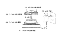
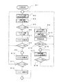
- FIG. 1 is an example 1 of a block diagram of an underwater light.
- the underwater light 50 is a product that can be separated and detached from the battery-mounted device 53 and the power receiving device 51 mounted on the light unit.
- the power receiving device 51 mounted on the light unit has various types of lights and can be replaced as appropriate.
- the battery of the battery-mounted device 53 is exhausted, it is fully charged separately prepared in advance. If you have the battery-equipped device 53, you can continue to use the light underwater by replacing it.
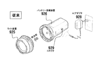
- the conventional underwater light has various problems.
- the configuration diagram of the conventional underwater light of FIG. 3 will be described.
- the conventional underwater light it is necessary to take it out of the water, wipe off the moisture of the fitting portion or the connecting portion sufficiently, and then replace the battery mounting device 926 and the light device 925. This is because there were factors such as leakage of electricity and deterioration of contact life such as electric leakage and salt biting of the connector when seawater got on.
- the battery can be charged by connecting the AC adapter 928 to the connector 929.
- This connector 929 must be used with a waterproof lid when underwater.
- a wireless power feeding mechanism is used to solve this problem. Furthermore, we devised a way to reduce the cost. I will explain it briefly. Configuration of the underwater light of FIG. 1 There is no electrical connector in the joint portion of FIG. Instead, the alignment joint and the wireless power receiving side 55 of the battery mounting device 53 have a built-in wireless power receiving coil that functions as wireless power feeding, and the wireless power receiving side 54 of the power receiving device 51 mounted on the light unit , The wireless power receiving coil is built-in. It is preferable to use a material which is mainly composed of resin and is not easily corroded for the joint portion and the joint portion.
- An LED 56 is provided in the joint portion of FIG.
- the LED When replacing the battery-equipped device and the light device in deep water such as deep diving, it is usually a pitch-black place where sunlight does not reach. At this time, if the only light goes out due to the battery running out, it will be a matter of life and death. Therefore, even if the LED runs out by arranging the LED in the joint part, it is lit by a small capacity battery for several minutes to facilitate replacement.
- the LED is installed in the mating portion, but if the purpose is to make the light device easier to see, it may be installed anywhere in the light device, not in the mating portion.
- the backup battery for example, a supercapacitor or the like may be used.
- a light emitting guide portion made of a phosphorescent material 52 is provided at an appropriate position in the mating portion.
- the phosphorescent material is a material that shines faintly for a while even without a light source when it is exposed to a certain light source. Even if the backup battery for the LED of the main unit is exhausted, the light emitting guide unit that glows with the light of the LED shines faintly for a while, so safety can be doubled.
- FIG. 2 is an example 2 of a configuration diagram of an underwater light.
- the battery-mounted device 53 of FIG. 1 when the battery-mounted device 53 of FIG. 1 is connected to the power receiving device 51 mounted on the light unit, the battery-mounted device 53 supplies wireless power, and the battery-mounted device 56 and the battery charging device 57 of FIG. When connected to, the battery-mounted device 56 has a wireless power receiving function. As a result, the battery-mounted device 56 does not have to be provided with a connector and a function for charging, which contributes to cost reduction and convenience.
- the battery-mounted device 56 has a built-in wireless power receiving / powering coil that functions as a wireless power receiving / power receiving side 58 on the wireless power receiving / feeding side 58, and wirelessly on the wireless power feeding side 59 of the battery charging device 57. It has a built-in power supply coil.
- the battery charging device 57 has a structure having protrusions by utilizing the dent of the battery mounting device 56. Unlike the light part, it does not need to be screwed in, and the battery-mounted device 56 is combined in a standing manner.
- the battery charging device 57 is connected to the AC adapter 60 to supply power. In the battery charging device 57, the connector portion with the AC adapter 60 does not need to be specially waterproofed.
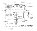
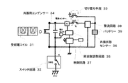
- the power supply device 10 of FIG. 4 has a power supply coil 11, a resonance capacitor 14 that constitutes a resonance circuit together with the power supply coil 11, a switch circuit 12 for turning power on and off the power supply coil 11, and a frequency supplied to the power supply coil 11. It includes a frequency adjusting circuit 15 for adjusting (for example, a circuit for adjusting a capacitor), a resonance state sensor 16 for detecting a resonance state, and a power supply 18.
- a frequency adjusting circuit 15 for adjusting for example, a circuit for adjusting a capacitor
- a resonance state sensor 16 for detecting a resonance state
- a power supply 18 for detecting a resonance state
- the features on the power supply device 10 side are listed. First, the feeding coil 11 and the resonance condenser 14 form a parallel resonance circuit. Second, there is one switch. Thirdly, the control circuit 17 controls the frequency adjustment circuit 15 and the switch circuit 12, and controls the frequency and the power supply time. Fourth, it has a resonance state sensor 16 that detects a resonance state (mainly a frequency shift
- FIG. 4 shows a basic circuit diagram (close to a block diagram).
- a power feeding coil 11 is provided to generate an electromagnetic wave to cause electromagnetic induction.
- At least the electric circuit of the power feeding device 10 is provided with a resonance capacitor 14 and a power supply 18, and forms a resonance relationship with the power receiving coil 1 of the power receiving device 2 at a constant frequency.
- the frequency at this time is referred to as a resonance frequency, and generally, a frequency from 100 kHz to 500 kHz is used.
- the resonance frequency used in the present invention is not particularly limited.
- the resonance frequency slightly deviates depending on the positional relationship and state of the power receiving device 2. For example, the situation changes depending on the position and inclination of the power receiving coil of the power receiving device 2. Therefore, if the power receiving coil 1 falls within the range of the electromagnetic wave transmitted from the power feeding coil 11 (within the magnetic flux lines shown in FIG. 1), energy can be supplied. The insertion of the power receiving coil 1 into the magnetic flux line affects the power feeding device side in the form of a deviation of the resonance frequency. If the resonance frequency shifts, the efficiency of energy supply decreases. Therefore, the shifted frequency and phase are detected by the resonance state sensor 16 (for example, a circuit including a phase detection circuit using a current sensor and a voltage sensor), and the frequency adjustment circuit 15 is used according to the frequency and phase. The frequency of the power feeding coil 11 is adjusted.
- the frequency adjusting circuit 15 is, for example, a circuit for adjusting the capacitance of the condenser.
- control circuit 17 that is controlled by a program using a microcontroller (integrated circuit including a processor, a memory, and peripheral circuits) or a programmable logic device (an integrated circuit in which an internal logic circuit can be defined / changed). ..
- the control circuit 17 is connected to the resonance state sensor 16 (phase detection circuit).
- the resonance state sensor 16 senses a frequency shift or a phase shift and transmits the signal to the control circuit 17.
- the resonance state sensor 16 detects an abnormal frequency or phase, transmits the signal to the control circuit 17, and the control circuit 17 stops the power supply. It becomes possible.
- a method of checking the heat generation state by temperature detection with a temperature sensor connected to a microcontroller to detect an abnormality and a method of detecting an overvoltage or an overcurrent by using a voltage / current detecting means to detect an abnormality. It is possible to make a safer system by using it together.
- the position of the resonance condenser 14 is at the position of ⁇ .
- a capacitor is connected in series with the feeding coil and is located at the ⁇ position.
- the reference of the resonance frequency can be adjusted by the specification of this condenser.
- the conventional connection method of this circuit is generally called a series resonant circuit.
- a parallel resonance circuit is adopted in the circuit of the power feeding device 10 of the wireless power feeding system in the present invention shown in FIG. 4, a parallel resonance circuit is adopted. In the circuit of FIG. 4, a method of detecting the resonance state can be used without stopping the feeding to the feeding coil 11.
- the wireless power supply system of the present invention is composed of the basic circuit shown in FIG.
- this parallel resonance circuit when SW1 is turned on and a stable resonance state is reached, and then SW1 is turned off, resonance with the power receiving device 2 is performed while the energy stored in the power receiving coil 1 and the capacitor 3 is released.
- the feature is that the power feeding device 10 continues the state.
- the ON / OFF timing of SW1 is controlled by using a PLL (Phase Locked Loop) circuit.
- the frequency adjustment circuit 15 and the control circuit 17 realize power supply of an appropriate frequency based on the transition of the resonance state detected by the resonance state sensor 16 connected in parallel with the power feeding coil 11.
- the resonance state sensor 16 is a sensor that detects the resonance state, and detects the transition of the voltage sensor / current sensor and the phase detection of the resonance frequency.
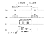
- FIG. 5 is a schematic diagram of a signal waveform of the basic circuit of the power feeding device 10 of FIG.
- FIG. 5A is a waveform of the switch circuit 12 of FIG. 4, which is switched on when it is high. That is, when the switch is turned on, the power supply 18 is supplied, so that the drive state, that is, the drive time. The time when the switch is turned off and not driven is the resonance state, that is, the resonance time.
- the power feeding device 10 is in a resonance state with the power receiving device 2 regardless of whether it is in the driving state or the resonance state. If so, continue to supply energy.
- FIG. 5B is a drive signal.
- the switch circuit 12 When the switch circuit 12 is on, the power supply 18 is turned on.
- FIG. 5C is a sampling signal detected by the resonance state sensor 16 of FIG. 1, and the signal is turned on a plurality of times during the sampling time to perform detection (sampling).
- FIG. 5D is a received signal input to the resonance state sensor 16 of FIG. This signal indicates the state of the feeding coil 11 in the resonant state. Although this signal waveform is shown briefly, it is a signal having frequency characteristics, and it is also possible to measure frequency components. Mainly, the voltage is converted into a digital value by an AD conversion circuit or the like, and information is sent to the control circuit 17 in FIG.
- the control circuit 17 adjusts the frequency at the time of power supply in cooperation with the frequency adjustment circuit 15 by judging these in a complex manner. Occasionally, the frequency is intentionally shifted back and forth to examine the change in the state shown in FIG. 5 (D). Further, when the power receiving device 2 is in a resonance state, the control circuit 17 also adjusts the drive time in consideration of how the voltage in FIG. 5D is reduced.
- executing the detection of the resonance state sensor 16 in FIG. 5C also involves a loss of energy as the power feeding device 10. Therefore, it is possible to suppress the energy loss by performing sampling intermittently, for example, once per second, instead of performing it every time.
- the specifications of the power supply 18, the power supply coil 11, and the resonance frequency are determined according to the size of the energy to be sent and the size and height of the area to be fed.
- the resonance capacitor 14 is mainly determined according to the specifications of the reference resonance frequency.
- the circuit of the power receiving device 2 includes a predetermined power receiving coil 1, and at least a condenser 3 and a rectifying circuit 4.
- the condenser 3 may be connected to the power receiving coil 1 in series or in parallel. In the present invention, it is ideal to connect in parallel.
- the power receiving device 2 has an internal battery 5 built-in.
- the internal battery 5 is a rechargeable secondary battery.
- a super capacitor electric double layer capacitor
- the specifications and volume of the power receiving coil 1 and the resonance frequency at this time are set according to the magnitude of the energy to be received, but it is also possible to give priority to the volume to be stored as the power receiving device 2.
- the power receiving device 2 When electromagnetic induction is generated from the power feeding coil 11 of the power feeding device 10 at a predetermined resonance frequency, magnetic flux is generated as shown in FIG.
- the power receiving coil 1 of the power receiving device 2 When the power receiving coil 1 of the power receiving device 2 is inserted at the tip of the magnetic flux line, electrical energy is generated by the electromotive force generated by electromagnetic induction. This energy is recovered and stored in the internal battery 5.
- the power receiving device 2 In the case of a general existing wireless power feeding device, the power receiving device 2 is often provided with a frequency detection circuit and a communication means to the power receiving device 10 that indicates the state of the power receiving device 2. ..
- the power feeding device 10 has a mechanism for transmitting to the power feeding device 10 by a communication means and appropriately adjusting the resonance frequency. In that case, the power receiving device 10 needs a predetermined IC circuit.
- the circuit of the power receiving device 2 is configured by a mechanism that simplifies to the utmost limit. With this simplified configuration, it is possible to discharge while charging, so while the charger is installed inside the electronic device, it is charged by the wireless power supply system, and at the same time it is discharged to the electronic device to generate electric power. It becomes possible to supply.
- FIG. 6 is an explanatory diagram of a circuit in which a power feeding unit and a power receiving unit are integrated.
- the wireless power feeding system of the battery-mounted device of the present invention is a wireless power receiving coil that combines a wireless power feeding coil and a wireless power receiving coil.
- the power supply circuit unit and the power reception circuit unit are mounted on one circuit board.
- the power receiving / feeding circuit unit was composed of a power receiving / power supply circuit unit capable of switching between the power supply mode and the power receiving mode by a predetermined switching means.
- the power receiving coil 1 and the power feeding coil 11 shown in FIG. 4 are shared by one power receiving coil 31. Further, it is characterized in that it is a power receiving / feeding circuit in which the circuit part of the power receiving device 2 and the circuit part of the power feeding device 10 are integrated. It is a circuit using the parallel resonance circuit proposed in the present invention, and the resonance capacitor 34 is connected in parallel with the coil.
- the switch SW2 of the switching means 33 is turned on to supply power from the battery, and the SW3 is turned off.
- this parallel resonance circuit when SW1 is turned on and a stable resonance state is reached, and then SW1 is turned off, resonance with the power receiving device is performed while the energy stored in the power receiving / feeding coil 31 and the condenser 34 is released. It is characterized by continuing the state.
- the frequency adjustment circuit 35 and the control circuit 37 realize power supply of an appropriate frequency based on the transition of the resonance state detected by the resonance state sensor 36 connected in parallel with the power receiving / feeding coil 31.
- the resonance state sensor 36 is a sensor that detects a resonance state, and detects a transition between voltage and current, phase detection of a resonance frequency, and the like.
- the state of the circuit in the power receiving mode in which power is received will be described.
- the switch SW2 of the switching means 33 is turned off and the SW3 is turned on. Also, SW1 is turned off. Electrical energy is generated by the electromotive force of the power receiving and feeding coil 31 due to electromagnetic induction. This energy passes through the rectifier circuit 38 and charges the battery 39.
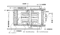
- FIG. 7 is a cross-sectional view of a connection portion between the battery-mounted device and the light device.
- the battery-mounted device main body 61 is provided with a ferrite coil A64 and is connected to the circuit board A63. Here, it is a board on which the wireless power receiving and feeding circuit shown in FIG. 6 is mounted.
- a battery 70 is connected to the circuit board A63.
- the ferrite coil A64 is also referred to as a wireless power receiving / feeding coil.
- the light device unit 62 is provided with a ferrite coil B65 and is connected to the circuit board B66. Here, it is a board on which the wireless power receiving and feeding circuit shown in FIG. 6 is mounted.
- the circuit board B66 is connected to LED69, which is a light.
- a protrusion 71 is provided at the connection between the battery-mounted device and the light device in FIG. 7.
- the battery-mounted device main body 61 is convex
- the light device 62 is concave
- the devices are combined.
- As a waterproof measure there is packing and the like, and the entire integrated portion of the battery-mounted device main body is concave, and the entire integrated portion of the light device 62 is convex. That is, the convex portion of the light device portion 62 is fitted into the concave portion of the battery mounting device main body 61 with the protrusion 71 as the center, or screwed into the recess.
- the ferrite coil A64 and the ferrite coil B65 are arranged so as to face each other with the thickness of the case in between.
- a magnet switch 67 is provided in the battery-mounted device main body 61 and a magnet 68 is provided in the light device 62 in order to detect whether the battery-mounted device main body 61 and the light device 62 are in a combined state. Has been done. At the time of matching, the magnet 68 turns on the magnet switch 67 and acts on the circuit board A63.
- the power supply efficiency of the wireless power supply is constant even if the light device 62 is rotated around the protrusion 71 in the wireless power supply. is there. Therefore, if there is a function of detecting the rotation position when the light device unit 62 is rotated, it is possible to provide a function of changing the intensity of the light depending on the rotation direction. Furthermore, it is possible to change the color of the light, or change the lighting and blinking, instead of changing the intensity of the light. Since several types of lights can be replaced on-site, it can be changed to a light for a suitable purpose and can be operated with multiple functions.
- the meaning of detecting the integrated state is to stop the wireless power supply when the integrated state is not performed, and to reduce the battery consumption.
- this switch mechanism should be provided. Is preferable.
- a method that does not use a magnet switch is also disclosed in the present invention, but will be described later.
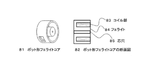
- FIG. 8 is a block diagram of the ferrite coil.
- the ferrite coils A and B of FIG. 7 are intentionally used as a pot-shaped ferrite core 81.
- This core has a structure that does not leak magnetic flux from the outside of the pot shape, and even when exposed to a conductive environment (metal or seawater), the leakage flux can be further suppressed. If the leakage magnetic flux is suppressed, the power supply efficiency is improved and the safety is improved. Further, during wireless power supply, the coil portion 83 may generate some heat, but the pot-shaped ferrite core has a heat dissipation effect as compared with the ferrite cores of other shapes.
- a pot-shaped ferrite core 81 As a schematic diagram of the pot-shaped ferrite core 81, a pot-shaped ferrite core 81 composed of a coil portion 83 wound by an electric wire, a ferrite 84, and a core hole 85 when a hole is formed in the center. is there.
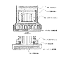
- FIG. 9 is a cross-sectional view of a connection portion between the battery-mounted device and the battery charging device.
- the battery and the mounting device 91 are provided with a ferrite coil A92 and are connected to the circuit board A93.
- the circuit board A93 is connected to the battery 94.
- the ferrite coil A92 is also referred to as a wireless power receiving / feeding coil.
- the battery power supply device 92 is provided with a ferrite coil C95 and is connected to the circuit board C96. Power is supplied to the circuit board C96 from an AC adapter or the like.
- the battery power supply device 92 has a drip-proof measure 97 mechanism on the assumption that the battery and the on-board device 91 are to be charged with water droplets on them.
- the drip-proof measure 97 is a case of a battery power supply device 92 made of a sponge-like material that absorbs water droplets and provided with air holes for natural evaporation. Further, as another method of the drip-proof measure 97, when the battery and the mounting device 91 are combined, the water droplets attached to the battery and the mounting device 91 may be pushed out and the water droplets may flow to the dish-shaped drip-proof measure 97. ..
- the dish-shaped drip-proof measure 97 is provided with a hole for allowing water droplets to escape in the case of the battery and the mounting device 91.
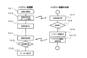
- FIG. 10 is a processing flow diagram of the battery-mounted main body.
- the battery-equipped main unit processes both wireless power supply and wireless power reception functions with the same coil and circuit. I will explain it step by step.
- the initialization process is various processes executed when the power is turned on.
- 8-2 is a power supply mode switching process in the standby state of wireless power supply.
- the wireless power supply process is performed in the low voltage drive state (8-3). In this state, for example, in addition to lowering the power supply voltage itself, the power supply is intermittently performed by taking a long time when the power supply is not performed to suppress the power consumption.
- the resonance state sensor 16 detects whether or not there is a power receiving side of the light device, and the sensor determines whether or not it is equal to or higher than the threshold value by the reaction 8-4. If the sensor does not respond, switch to wireless power receiving mode (8-6). Next, the wireless power receiving process of 8-7 is performed. From the detection of the resonance state sensor 16, it is determined by the reaction 8-8 to the sensor whether or not it is equal to or higher than the threshold value. From the next, it is an iterative process. 8-10 Wireless power reception processing is performed, and the sensor is judged by 8-11. Then, if stable power reception is performed from the reaction of the sensor, the battery power reception process is performed at 8-12. Returning to 8-9, it is repeated as long as it reacts to the sensor.
- the process returns to 8-1. If the 8-4 sensor responds, switch to the normal power supply mode of 8-5 wireless power supply. At 8-13, wireless power supply processing is performed with high voltage drive. A predetermined abnormality detection process is performed on 8-14. As a result of the abnormality detection, if the object is wirelessly supplied with power (8-15), the process returns to 8-16, otherwise the process returns to 8-1. If the object is normal, wireless power supply processing is performed at 8-17 with high voltage drive. Then, when the sensor stops responding, it returns to 8-1, and if there is a response, it returns to 8-16 and repeats the process. In this way, the mechanism for switching the wireless power supply / reception mode of the battery-mounted main unit has been described in the flow chart.
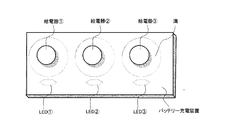
- FIG. 11 is a diagram of an example of a battery charging device.
- This battery charging device has a configuration in which the battery power supply device described in FIG. 9 is provided. In this way, it is a charging device that can charge the battery of three main bodies equipped with batteries at the same time.
- Each power supply is equipped with an LED status indicating that power is being supplied.
- each power supply unit is equipped with a groove, and the groove is waterproofed so that water droplets and the like are absorbed and discharged during power supply.
- FIG. 12 is a flow chart of an example of communication processing. Communication processing can be performed by a predetermined method during wireless power supply and wireless power reception. This method will be described later, but here, the execution steps will be described step by step in a flow diagram.
- the communication process is started at 10-1. Here, the process of storing the communication contents in the memory is mainly performed.
- the communication transmission process is performed. Communication transmission communicates in a polling format.
- the communication reception wait is performed. If communication is successful, the response value will be returned, so wait for reception for a certain period of time.
- the communication reception process is performed at 10-4.
- the 10-5 full charge determination process is performed.
- the LED in FIG. 11 is changed from red lighting to green lighting.
- the battery-mounted main body There is a 10-7 communication reception process for receiving the communication content transmitted from the communication process of 10-2.
- the battery capacity is measured, the battery capacity value of 10-10 is returned, and the response is transmitted.
- this communication means two-way communication, it is possible to have various functions.
- the power receiving device mounted on the light unit is equipped with a means for recording the amount of light emitted, and when the main body equipped with the battery and the light unit are connected to perform wireless power supply, the numerical value of the amount of light emitted is received by the communication means. It is also possible to store it in the memory of the main body of the battery.
- the wireless power supply system of the present invention has a configuration particularly suitable for an underwater camera. It can also be applied not only to water, but also to dusty environments and products that are safe for children to handle.
- a light that wants to freely rotate in the direction of rotation can be connected to the main body equipped with a battery, and is not limited to the light, but can be applied to any destination (energy consumption circuit section) that wants to supply power.
Landscapes
- Engineering & Computer Science (AREA)
- Power Engineering (AREA)
- General Engineering & Computer Science (AREA)
- Computer Networks & Wireless Communication (AREA)
- Manufacturing & Machinery (AREA)
- Chemical & Material Sciences (AREA)
- Chemical Kinetics & Catalysis (AREA)
- Electrochemistry (AREA)
- General Chemical & Material Sciences (AREA)
- Electromagnetism (AREA)
- Physics & Mathematics (AREA)
- Microelectronics & Electronic Packaging (AREA)
- Charge And Discharge Circuits For Batteries Or The Like (AREA)
- Secondary Cells (AREA)
Priority Applications (4)
| Application Number | Priority Date | Filing Date | Title |
|---|---|---|---|
| EP20777859.8A EP3952002A4 (en) | 2019-03-28 | 2020-03-24 | WIRELESS POWER SUPPLY SYSTEM WITH BATTERY MOUNTED DEVICE INTERLOCKED WITH A POWER RECEIVING DEVICE WITH LIGHT UNIT MOUNTED |
| JP2021509446A JP7105428B2 (ja) | 2019-03-28 | 2020-03-24 | ライト部搭載の受電装置と篏合するバッテリー搭載装置を有するワイヤレス給電システム |
| CN202080024987.4A CN113661596B (zh) | 2019-03-28 | 2020-03-24 | 具有与搭载灯部的受电装置嵌合的电池搭载装置的无线馈电系统 |
| US17/593,918 US12247728B2 (en) | 2019-03-28 | 2020-03-24 | Wireless power feeding system having battery mounted device engaged with power receiving device with light unit mounted device |
Applications Claiming Priority (2)
| Application Number | Priority Date | Filing Date | Title |
|---|---|---|---|
| JP2019-062924 | 2019-03-28 | ||
| JP2019062924 | 2019-03-28 |
Publications (1)
| Publication Number | Publication Date |
|---|---|
| WO2020196508A1 true WO2020196508A1 (ja) | 2020-10-01 |
Family
ID=72611982
Family Applications (1)
| Application Number | Title | Priority Date | Filing Date |
|---|---|---|---|
| PCT/JP2020/012993 Ceased WO2020196508A1 (ja) | 2019-03-28 | 2020-03-24 | ライト部搭載の受電装置と篏合するバッテリー搭載装置を有するワイヤレス給電システム |
Country Status (5)
| Country | Link |
|---|---|
| US (1) | US12247728B2 (enExample) |
| EP (1) | EP3952002A4 (enExample) |
| JP (1) | JP7105428B2 (enExample) |
| CN (1) | CN113661596B (enExample) |
| WO (1) | WO2020196508A1 (enExample) |
Families Citing this family (1)
| Publication number | Priority date | Publication date | Assignee | Title |
|---|---|---|---|---|
| EP4556791A1 (en) * | 2023-11-17 | 2025-05-21 | Smart Electric Works Co.,Ltd. | Wireless powered waterproof track light |
Citations (17)
| Publication number | Priority date | Publication date | Assignee | Title |
|---|---|---|---|---|
| JP2006517778A (ja) * | 2003-02-04 | 2006-07-27 | アクセス ビジネス グループ インターナショナル リミテッド ライアビリティ カンパニー | 通信手段を持つ適応誘導電源 |
| JP2011151958A (ja) | 2010-01-21 | 2011-08-04 | Sony Corp | 給電装置、受電装置、およびワイヤレス給電システム |
| JP2011217596A (ja) | 2010-03-19 | 2011-10-27 | Tdk Corp | ワイヤレス給電装置、ワイヤレス受電装置およびワイヤレス電力伝送システム |
| JP2011223739A (ja) | 2010-04-09 | 2011-11-04 | Sony Corp | 給電装置、受電装置、およびワイヤレス給電システム |
| JP2012502612A (ja) * | 2008-09-02 | 2012-01-26 | クゥアルコム・インコーポレイテッド | 双方向無線電力転送 |
| JP2012182975A (ja) | 2011-03-01 | 2012-09-20 | Tdk Corp | ワイヤレス給電装置およびワイヤレス電力伝送システム |
| JP2012231674A (ja) | 2009-07-24 | 2012-11-22 | Tdk Corp | ワイヤレス給電装置およびワイヤレス電力伝送システム |
| JP2012253944A (ja) | 2011-06-03 | 2012-12-20 | Advantest Corp | ワイヤレス給電装置およびワイヤレス給電システム |
| JP2013524743A (ja) | 2010-04-02 | 2013-06-17 | 株式会社アドバンテスト | ワイヤレス受電装置およびワイヤレス給電システム |
| JP2013162611A (ja) | 2012-02-03 | 2013-08-19 | Seiko Instruments Inc | ワイヤレス給電装置 |
| JP2013172506A (ja) * | 2012-02-20 | 2013-09-02 | Sumitomo Electric Ind Ltd | 非接触給電システム、非接触給電装置、非接触受電装置及び非接触給電方法 |
| JP2014068507A (ja) | 2012-09-27 | 2014-04-17 | Tdk Corp | ワイヤレス給電システム |
| JP2014176122A (ja) | 2013-03-06 | 2014-09-22 | Osaka City Univ | 磁気共振型ワイヤレス給電システム |
| JP2015525482A (ja) * | 2012-06-11 | 2015-09-03 | パワーバイプロキシ リミテッド | 無線電力伝達システムで使用される導磁コア |
| JP2017028998A (ja) | 2012-10-11 | 2017-02-02 | 株式会社村田製作所 | ワイヤレス給電装置 |
| JP2017028770A (ja) | 2015-07-16 | 2017-02-02 | 清水建設株式会社 | ワイヤレス給電システム |
| JP2017163647A (ja) | 2016-03-08 | 2017-09-14 | 達也 土井 | 電磁界共振ワイヤレス給電方法及び給電システム |
Family Cites Families (24)
| Publication number | Priority date | Publication date | Assignee | Title |
|---|---|---|---|---|
| KR100736053B1 (ko) | 2005-10-24 | 2007-07-06 | 삼성전자주식회사 | 유도 방식에 의해 무선으로 전원을 공유하는 장치 및 방법 |
| JP5096798B2 (ja) * | 2007-05-25 | 2012-12-12 | 株式会社エヌ・ティ・ティ・ドコモ | 給電受信装置、通信システム、及びこれらの方法 |
| JP5277858B2 (ja) * | 2008-10-20 | 2013-08-28 | トヨタ自動車株式会社 | 給電システム及び移動体用給電装置 |
| CN102195366B (zh) * | 2010-03-19 | 2014-03-12 | Tdk株式会社 | 无线馈电装置以及无线电力传输系统 |
| JP2011234605A (ja) * | 2010-04-05 | 2011-11-17 | Tdk Corp | ワイヤレス受電装置およびワイヤレス電力伝送システム |
| JP2012019648A (ja) * | 2010-07-09 | 2012-01-26 | Sony Corp | 給電装置およびワイヤレス給電システム |
| JP5640530B2 (ja) * | 2010-07-30 | 2014-12-17 | ソニー株式会社 | ワイヤレス給電システム |
| US20140361734A1 (en) | 2010-09-17 | 2014-12-11 | Sony Corporation | Power supply method, charging control device, and power supply system |
| KR101045585B1 (ko) * | 2010-09-29 | 2011-06-30 | 한국과학기술원 | 전자기파의 누설이 저감된 무선전력전송장치 |
| US9178369B2 (en) | 2011-01-18 | 2015-11-03 | Mojo Mobility, Inc. | Systems and methods for providing positioning freedom, and support of different voltages, protocols, and power levels in a wireless power system |
| US9887583B2 (en) * | 2011-03-10 | 2018-02-06 | Semiconductor Energy Laboratory Co., Ltd. | Power-receiving device, wireless power-feeding system including power-receiving device, and wireless communication system including power-receiving device |
| US9099885B2 (en) * | 2011-06-17 | 2015-08-04 | Semiconductor Energy Laboratory Co., Ltd. | Wireless power feeding system |
| JP2013055856A (ja) * | 2011-09-06 | 2013-03-21 | Heads Corp | 非接触電力供給装置 |
| JP2013183596A (ja) * | 2012-03-05 | 2013-09-12 | Nagasaki Univ | 無線電力伝送装置および無線電力伝送システム |
| JP5929493B2 (ja) * | 2012-05-17 | 2016-06-08 | ソニー株式会社 | 受電装置、および、給電システム |
| US20140008993A1 (en) * | 2012-07-06 | 2014-01-09 | DvineWave Inc. | Methodology for pocket-forming |
| JP6104539B2 (ja) * | 2012-09-06 | 2017-03-29 | 日立マクセル株式会社 | 非接触充電システム |
| CN105706333A (zh) | 2013-10-28 | 2016-06-22 | 京瓷株式会社 | 控制装置 |
| JP6366318B2 (ja) * | 2014-03-26 | 2018-08-01 | マクセルホールディングス株式会社 | 非接触電力伝送手段を備えた電源 |
| JP2015220891A (ja) * | 2014-05-19 | 2015-12-07 | 日本特殊陶業株式会社 | 共振器及び無線給電システム |
| JP2016013020A (ja) * | 2014-06-30 | 2016-01-21 | 村田機械株式会社 | 非接触給電装置、非接触給電システム及び非接触給電装置の制御方法 |
| WO2016191423A1 (en) * | 2015-05-28 | 2016-12-01 | Nike Innovate C.V. | Transportation apparatus with nfc charger |
| JP2017103858A (ja) | 2015-11-30 | 2017-06-08 | オムロン株式会社 | 非接触給電システム |
| CN208074810U (zh) | 2018-01-25 | 2018-11-09 | 深圳市杰恩特户外用品有限公司 | 一种带无线充电和供电能在水中更换电池的照明设备 |
-
2020
- 2020-03-24 JP JP2021509446A patent/JP7105428B2/ja active Active
- 2020-03-24 EP EP20777859.8A patent/EP3952002A4/en active Pending
- 2020-03-24 WO PCT/JP2020/012993 patent/WO2020196508A1/ja not_active Ceased
- 2020-03-24 CN CN202080024987.4A patent/CN113661596B/zh active Active
- 2020-03-24 US US17/593,918 patent/US12247728B2/en active Active
Patent Citations (18)
| Publication number | Priority date | Publication date | Assignee | Title |
|---|---|---|---|---|
| JP2006517778A (ja) * | 2003-02-04 | 2006-07-27 | アクセス ビジネス グループ インターナショナル リミテッド ライアビリティ カンパニー | 通信手段を持つ適応誘導電源 |
| JP2012502612A (ja) * | 2008-09-02 | 2012-01-26 | クゥアルコム・インコーポレイテッド | 双方向無線電力転送 |
| JP2012231674A (ja) | 2009-07-24 | 2012-11-22 | Tdk Corp | ワイヤレス給電装置およびワイヤレス電力伝送システム |
| JP2011151958A (ja) | 2010-01-21 | 2011-08-04 | Sony Corp | 給電装置、受電装置、およびワイヤレス給電システム |
| JP2011217596A (ja) | 2010-03-19 | 2011-10-27 | Tdk Corp | ワイヤレス給電装置、ワイヤレス受電装置およびワイヤレス電力伝送システム |
| JP2013524743A (ja) | 2010-04-02 | 2013-06-17 | 株式会社アドバンテスト | ワイヤレス受電装置およびワイヤレス給電システム |
| JP2011223739A (ja) | 2010-04-09 | 2011-11-04 | Sony Corp | 給電装置、受電装置、およびワイヤレス給電システム |
| JP2012182975A (ja) | 2011-03-01 | 2012-09-20 | Tdk Corp | ワイヤレス給電装置およびワイヤレス電力伝送システム |
| JP2012253944A (ja) | 2011-06-03 | 2012-12-20 | Advantest Corp | ワイヤレス給電装置およびワイヤレス給電システム |
| JP2013162611A (ja) | 2012-02-03 | 2013-08-19 | Seiko Instruments Inc | ワイヤレス給電装置 |
| JP2013172506A (ja) * | 2012-02-20 | 2013-09-02 | Sumitomo Electric Ind Ltd | 非接触給電システム、非接触給電装置、非接触受電装置及び非接触給電方法 |
| JP2015525482A (ja) * | 2012-06-11 | 2015-09-03 | パワーバイプロキシ リミテッド | 無線電力伝達システムで使用される導磁コア |
| JP2014068507A (ja) | 2012-09-27 | 2014-04-17 | Tdk Corp | ワイヤレス給電システム |
| JP2017028998A (ja) | 2012-10-11 | 2017-02-02 | 株式会社村田製作所 | ワイヤレス給電装置 |
| JP2018183051A (ja) | 2012-10-11 | 2018-11-15 | 株式会社村田製作所 | ワイヤレス給電装置 |
| JP2014176122A (ja) | 2013-03-06 | 2014-09-22 | Osaka City Univ | 磁気共振型ワイヤレス給電システム |
| JP2017028770A (ja) | 2015-07-16 | 2017-02-02 | 清水建設株式会社 | ワイヤレス給電システム |
| JP2017163647A (ja) | 2016-03-08 | 2017-09-14 | 達也 土井 | 電磁界共振ワイヤレス給電方法及び給電システム |
Also Published As
| Publication number | Publication date |
|---|---|
| US12247728B2 (en) | 2025-03-11 |
| CN113661596A (zh) | 2021-11-16 |
| US20220178530A1 (en) | 2022-06-09 |
| JPWO2020196508A1 (enExample) | 2020-10-01 |
| EP3952002A4 (en) | 2023-04-19 |
| EP3952002A1 (en) | 2022-02-09 |
| JP7105428B2 (ja) | 2022-07-25 |
| CN113661596B (zh) | 2024-09-06 |
Similar Documents
| Publication | Publication Date | Title |
|---|---|---|
| US8159182B2 (en) | Contactless power transferring coil unit, mobile terminal, power transmitting apparatus, and contactless power transferring system | |
| US9438066B2 (en) | Contactless rechargeable secondary battery and contactless battery charger | |
| US6208115B1 (en) | Battery substitute pack | |
| CN103828174B (zh) | 具有用于电池组的无线通信装置的独立能量供给装置的电池组 | |
| RU2440635C1 (ru) | Бесконтактная система электропитания | |
| EP2973939B1 (en) | Systems and methods for extending the power capability of a wireless charger | |
| EP2278654B1 (en) | Contactless cell apparatus | |
| US9191075B2 (en) | Wireless power control method, system, and apparatus utilizing a wakeup signal to prevent standby power consumption | |
| EP3008830B1 (en) | System and method for delayed application processor initialization in wireless power transmission system | |
| KR102312942B1 (ko) | 배터리 관리 장치 및 이를 포함하는 배터리 팩 | |
| KR20140114487A (ko) | 무선 전력 전송 장치 및 무선 전력 수신 장치 | |
| JP6192028B2 (ja) | 非接触充電システム | |
| JP6665568B2 (ja) | 制御装置、受電装置、電子機器、電力伝送システム及び電力供給方法 | |
| JP2011114911A (ja) | 充電制御装置および電子時計 | |
| CN115152125A (zh) | 具有调谐调整电路的无线功率馈送系统 | |
| JP7105428B2 (ja) | ライト部搭載の受電装置と篏合するバッテリー搭載装置を有するワイヤレス給電システム | |
| KR102822700B1 (ko) | 무선급전시스템 및 원형 구형 다면형상을 갖는 수전기 | |
| KR20190026424A (ko) | 무선 충전 방법 및 그를 위한 장치 및 시스템 | |
| JP2011062037A (ja) | 非接触式充電システム | |
| JPWO2020196508A5 (enExample) | ||
| KR20070074719A (ko) | 충전 회로부와 코일부가 분리된 무접점 충전장치 | |
| WO2025259532A1 (en) | A wirelessly rechargeable battery for powering devices designed to operate using standardized alkaline and nimh battery cells | |
| KR20180042032A (ko) | 무선 전력 전송 시스템에서 무선 전력 중계기 및 송신기 | |
| IL120990A (en) | Contactless rechargeable battery |
Legal Events
| Date | Code | Title | Description |
|---|---|---|---|
| 121 | Ep: the epo has been informed by wipo that ep was designated in this application |
Ref document number: 20777859 Country of ref document: EP Kind code of ref document: A1 |
|
| ENP | Entry into the national phase |
Ref document number: 2021509446 Country of ref document: JP Kind code of ref document: A |
|
| NENP | Non-entry into the national phase |
Ref country code: DE |
|
| ENP | Entry into the national phase |
Ref document number: 2020777859 Country of ref document: EP Effective date: 20211028 |
|
| WWG | Wipo information: grant in national office |
Ref document number: 17593918 Country of ref document: US |