EP2973939B1 - Systems and methods for extending the power capability of a wireless charger - Google Patents
Systems and methods for extending the power capability of a wireless charger Download PDFInfo
- Publication number
- EP2973939B1 EP2973939B1 EP14708466.9A EP14708466A EP2973939B1 EP 2973939 B1 EP2973939 B1 EP 2973939B1 EP 14708466 A EP14708466 A EP 14708466A EP 2973939 B1 EP2973939 B1 EP 2973939B1
- Authority
- EP
- European Patent Office
- Prior art keywords
- transmit antenna
- transmit
- receiver
- antenna
- wireless field
- Prior art date
- Legal status (The legal status is an assumption and is not a legal conclusion. Google has not performed a legal analysis and makes no representation as to the accuracy of the status listed.)
- Active
Links
- 238000000034 method Methods 0.000 title claims description 25
- 238000012546 transfer Methods 0.000 claims description 138
- 238000010168 coupling process Methods 0.000 claims description 32
- 230000008878 coupling Effects 0.000 claims description 31
- 238000005859 coupling reaction Methods 0.000 claims description 31
- 230000004907 flux Effects 0.000 claims description 28
- 238000004891 communication Methods 0.000 claims description 22
- 230000003213 activating effect Effects 0.000 claims description 8
- 238000005259 measurement Methods 0.000 claims 3
- 238000012545 processing Methods 0.000 claims 1
- 238000010586 diagram Methods 0.000 description 25
- 239000003990 capacitor Substances 0.000 description 8
- 230000006870 function Effects 0.000 description 8
- 230000008901 benefit Effects 0.000 description 6
- 230000001276 controlling effect Effects 0.000 description 6
- 230000001965 increasing effect Effects 0.000 description 6
- 230000005540 biological transmission Effects 0.000 description 5
- 238000006243 chemical reaction Methods 0.000 description 5
- 238000001514 detection method Methods 0.000 description 5
- 230000011664 signaling Effects 0.000 description 5
- 241000282412 Homo Species 0.000 description 4
- 238000006073 displacement reaction Methods 0.000 description 4
- 230000001105 regulatory effect Effects 0.000 description 4
- 230000033228 biological regulation Effects 0.000 description 3
- 230000005672 electromagnetic field Effects 0.000 description 3
- 230000001976 improved effect Effects 0.000 description 3
- 230000001939 inductive effect Effects 0.000 description 3
- 239000000463 material Substances 0.000 description 3
- 230000007246 mechanism Effects 0.000 description 3
- 230000004044 response Effects 0.000 description 3
- 229910000859 α-Fe Inorganic materials 0.000 description 3
- 230000008859 change Effects 0.000 description 2
- 238000005516 engineering process Methods 0.000 description 2
- 230000006698 induction Effects 0.000 description 2
- 230000003287 optical effect Effects 0.000 description 2
- 239000002245 particle Substances 0.000 description 2
- 230000002093 peripheral effect Effects 0.000 description 2
- 230000001902 propagating effect Effects 0.000 description 2
- 238000004804 winding Methods 0.000 description 2
- 230000009471 action Effects 0.000 description 1
- 230000003044 adaptive effect Effects 0.000 description 1
- 230000006399 behavior Effects 0.000 description 1
- 230000001413 cellular effect Effects 0.000 description 1
- 239000004020 conductor Substances 0.000 description 1
- 230000007812 deficiency Effects 0.000 description 1
- 230000005684 electric field Effects 0.000 description 1
- 230000005670 electromagnetic radiation Effects 0.000 description 1
- 230000003993 interaction Effects 0.000 description 1
- 239000002184 metal Substances 0.000 description 1
- 230000008569 process Effects 0.000 description 1
- 230000000644 propagated effect Effects 0.000 description 1
- 230000009467 reduction Effects 0.000 description 1
Images


Classifications
-
- H—ELECTRICITY
- H02—GENERATION; CONVERSION OR DISTRIBUTION OF ELECTRIC POWER
- H02J—CIRCUIT ARRANGEMENTS OR SYSTEMS FOR SUPPLYING OR DISTRIBUTING ELECTRIC POWER; SYSTEMS FOR STORING ELECTRIC ENERGY
- H02J50/00—Circuit arrangements or systems for wireless supply or distribution of electric power
- H02J50/40—Circuit arrangements or systems for wireless supply or distribution of electric power using two or more transmitting or receiving devices
- H02J50/402—Circuit arrangements or systems for wireless supply or distribution of electric power using two or more transmitting or receiving devices the two or more transmitting or the two or more receiving devices being integrated in the same unit, e.g. power mats with several coils or antennas with several sub-antennas
-
- H—ELECTRICITY
- H02—GENERATION; CONVERSION OR DISTRIBUTION OF ELECTRIC POWER
- H02J—CIRCUIT ARRANGEMENTS OR SYSTEMS FOR SUPPLYING OR DISTRIBUTING ELECTRIC POWER; SYSTEMS FOR STORING ELECTRIC ENERGY
- H02J50/00—Circuit arrangements or systems for wireless supply or distribution of electric power
- H02J50/10—Circuit arrangements or systems for wireless supply or distribution of electric power using inductive coupling
- H02J50/12—Circuit arrangements or systems for wireless supply or distribution of electric power using inductive coupling of the resonant type
-
- H—ELECTRICITY
- H02—GENERATION; CONVERSION OR DISTRIBUTION OF ELECTRIC POWER
- H02J—CIRCUIT ARRANGEMENTS OR SYSTEMS FOR SUPPLYING OR DISTRIBUTING ELECTRIC POWER; SYSTEMS FOR STORING ELECTRIC ENERGY
- H02J50/00—Circuit arrangements or systems for wireless supply or distribution of electric power
- H02J50/60—Circuit arrangements or systems for wireless supply or distribution of electric power responsive to the presence of foreign objects, e.g. detection of living beings
-
- H—ELECTRICITY
- H02—GENERATION; CONVERSION OR DISTRIBUTION OF ELECTRIC POWER
- H02J—CIRCUIT ARRANGEMENTS OR SYSTEMS FOR SUPPLYING OR DISTRIBUTING ELECTRIC POWER; SYSTEMS FOR STORING ELECTRIC ENERGY
- H02J50/00—Circuit arrangements or systems for wireless supply or distribution of electric power
- H02J50/70—Circuit arrangements or systems for wireless supply or distribution of electric power involving the reduction of electric, magnetic or electromagnetic leakage fields
-
- H—ELECTRICITY
- H02—GENERATION; CONVERSION OR DISTRIBUTION OF ELECTRIC POWER
- H02J—CIRCUIT ARRANGEMENTS OR SYSTEMS FOR SUPPLYING OR DISTRIBUTING ELECTRIC POWER; SYSTEMS FOR STORING ELECTRIC ENERGY
- H02J50/00—Circuit arrangements or systems for wireless supply or distribution of electric power
- H02J50/80—Circuit arrangements or systems for wireless supply or distribution of electric power involving the exchange of data, concerning supply or distribution of electric power, between transmitting devices and receiving devices
-
- H04B5/79—
-
- H—ELECTRICITY
- H02—GENERATION; CONVERSION OR DISTRIBUTION OF ELECTRIC POWER
- H02J—CIRCUIT ARRANGEMENTS OR SYSTEMS FOR SUPPLYING OR DISTRIBUTING ELECTRIC POWER; SYSTEMS FOR STORING ELECTRIC ENERGY
- H02J7/00—Circuit arrangements for charging or depolarising batteries or for supplying loads from batteries
- H02J7/00032—Circuit arrangements for charging or depolarising batteries or for supplying loads from batteries characterised by data exchange
- H02J7/00034—Charger exchanging data with an electronic device, i.e. telephone, whose internal battery is under charge
-
- H04B5/24—
Definitions
- the present invention relates generally to wireless power. More specifically, the disclosure is directed to transmitters and receivers in a wireless power transfer system.
- An increasing number and variety of electronic devices are powered via rechargeable batteries. Such devices include mobile phones, portable music players, laptop computers, tablet computers, computer peripheral devices, communication devices (e.g., Bluetooth devices), digital cameras, hearing aids, and the like. While battery technology has improved, battery-powered electronic devices increasingly require and consume greater amounts of power, thereby often requiring recharging. Rechargeable devices are often charged via wired connections through cables or other similar connectors that are physically connected to a power supply. Cables and similar connectors may sometimes be inconvenient or cumbersome and have other drawbacks. Wireless charging systems that are capable of transferring power in free space to be used to charge rechargeable electronic devices or provide power to electronic devices may overcome some of the deficiencies of wired charging solutions. As such, wireless power transfer systems and methods that efficiently and safely transfer power to electronic devices are desirable, see for example US2011/0156640 .
- the apparatus comprises a first transmit antenna configured to generate a first wireless field when the at least one receiver is in an energy transfer region of the first transmit antenna.
- the apparatus further comprises a second transmit antenna spatially separated from the first transmit antenna, the second transmit antenna configured to generate a second wireless field when the at least one receiver is in an energy transfer region of the second transmit antenna.
- the apparatus further comprises a controller operationally coupled to the first transmit antenna and the second transmit antenna and configured to activate at least one of the first transmit antenna or the second transmit antenna based on whether the at least one receiver is in an energy transfer region of one or both of the first wireless field and the second wireless field.
- the controller may be further configured to control, when both the first transmit antenna and the second transmit antenna are activated, whether the first transmit antenna and the second transmit antenna independently transfer energy wirelessly to a same receiver via the first and second wireless fields, whether the first transmit antenna and the second transmit antenna jointly transfer energy wirelessly to the same receiver via the first and second wireless fields, or whether the first transmit antenna and the second transmit antenna transfer energy wirelessly to different receivers via the first and second wirelessly fields.
- Another aspect of the disclosure provides a method of transferring energy wirelessly to at least one receive antenna of at least one receiver according to claim 6.
- the method comprises generating, by a first transmit antenna, a first wireless field when the at least one receiver is in an energy transfer region of the first transmit antenna.
- the method further comprises generating, by a second transmit antenna spatially separated from the first transmit antenna, a second wireless field when the at least one receiver is in an energy transfer region of the second transmit antenna.
- the method further comprises activating at least one of the first transmit antenna or the second transmit antenna based on whether the at least one receiver is in an energy transfer region of one or both of the first wireless field and the second wireless field.
- the method further comprises controlling, when both the first transmit antenna and the second transmit antenna are activated, whether the first transmit antenna and the second transmit antenna independently transfer energy wirelessly to a same receiver via the first and second wireless fields, whether the first transmit antenna and the second transmit antenna jointly transfer energy wirelessly to the same receiver via the first and second wireless fields, or whether the first transmit antenna and the second transmit antenna transfer energy wirelessly to different receivers via the first and second wirelessly fields.
- the apparatus comprises means for generating a first wireless field when the at least one receiver is in an energy transfer region of the means for generating the first wireless field.
- the apparatus further comprises means for generating a second wireless field when the at least one receiver is in an energy transfer region of the means for generating the second wireless field.
- the apparatus further comprises means for activating at least one of the means for generating the first wireless field or the means for generating the second wireless field based on whether the at least one receiver is in an energy transfer region of one or both of the first wireless field and the second wireless field.
- the apparatus further comprises means for controlling, when both the means for generating the first wireless field and the means for generating the second wireless field are activated, whether the means for generating the first wireless field and the means for generating the second wireless field independently transfer energy wirelessly to a same receiver via the first and second wireless fields, whether the means for generating the first wireless field and the means for generating the second wireless field jointly transfer energy wirelessly to the same receiver via the first and second wireless fields, or whether the means for generating the first wireless field and the means for generating the second wireless field transfer energy wirelessly to different receivers via the first and second wirelessly fields.
- Non-transitory computer-readable medium comprising code that, when executed, causes an apparatus to generate, using a first transmit antenna, a first wireless field when at least one receiver is in an energy transfer region of the first transmit antenna.
- the medium further comprises code that, when executed, causes an apparatus to generate, using a second transmit antenna spatially separated from the first transmit antenna, a second wireless field when the at least one receiver is in an energy transfer region of the second transmit antenna.
- the medium further comprises code that, when executed, causes an apparatus to activate at least one of the first transmit antenna or the second transmit antenna based on whether the at least one receiver is in an energy transfer region of one or both of the first wireless field and the second wireless field.
- the medium further comprises code that, when executed, causes an apparatus to control, when both the first transmit antenna and the second transmit antenna are activated, whether the first transmit antenna and the second transmit antenna independently transfer energy wirelessly to a same receiver via the first and second wireless fields, whether the first transmit antenna and the second transmit antenna jointly transfer energy wirelessly to the same receiver via the first and second wireless fields, or whether the first transmit antenna and the second transmit antenna transfer energy wirelessly to different receivers via the first and second wirelessly fields.
- Wirelessly transferring power may refer to transferring any form of energy associated with electric fields, magnetic fields, electromagnetic fields, or otherwise from a transmitter to a receiver without the use of physical electrical conductors (e.g., power may be transferred through free space).
- the power output into a wireless field e.g., a magnetic field or an electromagnetic field
- a receiving antenna to achieve power transfer.
- two components being “coupled” may refer to their interaction through direct or indirect ways, and may further refer to a physically connected (e.g. wired) coupling or a physically disconnected (e.g. wireless) coupling.
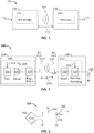
- FIG. 1 is a functional block diagram of an exemplary wireless power transfer system 100, in accordance with exemplary embodiments of the invention.
- Input power 102 may be provided to a transmitter 104 from a power source (not shown) for generating a field 105 for providing energy transfer.
- a receiver 108 may couple to the field 105 and generate output power 110 for storing or consumption by a device (not shown) coupled to the output power 110.
- Both the transmitter 104 and the receiver 108 are separated by a distance 112.
- transmitter 104 and receiver 108 are configured according to a mutual resonant relationship. When the resonant frequency of receiver 108 and the resonant frequency of transmitter 104 are substantially the same or very close, transmission losses between the transmitter 104 and the receiver 108 are minimal.
- wireless power transfer may be provided over larger distance in contrast to purely inductive solutions that may require large coils to be very close (e.g., mms).
- Resonant inductive coupling techniques may thus allow for improved efficiency and power transfer over various distances and with a variety of inductive coil configurations.
- the receiver 108 may receive power when the receiver 108 is located in an energy field 105 produced by the transmitter 104.
- the field 105 corresponds to a region where energy output by the transmitter 104 may be captured by a receiver 105. In some cases, the field 105 may correspond to the "near-field" of the transmitter 104 as will be further described below.
- the transmitter 104 may include a transmit antenna 114 (e.g., a transmit coil) for outputting an energy transmission.
- the receiver 108 further includes a receive antenna 118 (e.g., a receive coil) for receiving or capturing energy from the energy transmission.
- the near-field may correspond to a region in which there are strong reactive fields resulting from the currents and charges in the transmit antenna 114 that minimally radiate power away from the transmit antenna 114. In some cases the near-field may correspond to a region that is within about one wavelength (or a fraction thereof) of the transmit antenna 114.
- the transmit and receive antennas 114 and 118 are sized according to applications and devices to be associated therewith. As described above, efficient energy transfer may occur by coupling a large portion of the energy in a field 105 of the transmit antenna 114 to a receive antenna 118 rather than propagating most of the energy in an electromagnetic wave to the far field. When positioned within the field 105, a "coupling mode" may be developed between the transmit antenna 114 and the receive antenna 118. The area around the transmit and receive antennas 114 and 118 where this coupling may occur is referred to herein as a coupling-mode region.
- FIG. 2 is a functional block diagram of exemplary components that may be used in the wireless power transfer system 100 of FIG. 1 , in accordance with various exemplary embodiments of the invention.
- the transmitter 204 may include transmit circuitry 206 that may include an oscillator 222, a driver circuit 224, and a filter and matching circuit 226.
- the oscillator 222 may be configured to generate a signal at a desired frequency, such as 468.75 KHz, 6.78 MHz or 13.56 MHz, that may be adjusted in response to a frequency control signal 223.
- the oscillator signal may be provided to a driver circuit 224 configured to drive the transmit antenna 214 at, for example, a resonant frequency of the transmit antenna 214.
- the driver circuit 224 may be a switching amplifier configured to receive a square wave from the oscillator 222 and output a sine wave.
- the driver circuit 224 may be a class E amplifier.
- a filter and matching circuit 226 may be also included to filter out harmonics or other unwanted frequencies and match the impedance of the transmitter 204 to the transmit antenna 214.
- the transmitter 204 may wirelessly output power at a level sufficient for charging or powering an electronic device.
- the power provided may be for example on the order of 300 milliWatts to 5 Watts to power or charge different devices with different power requirements. Higher or lower power levels may also be provided.
- the receiver 208 may include receive circuitry 210 that may include a matching circuit 232 and a rectifier and switching circuit 234 to generate a DC power output from an AC power input to charge a battery 236 as shown in FIG. 2 or to power a device (not shown) coupled to the receiver 108.
- the matching circuit 232 may be included to match the impedance of the receive circuitry 210 to the receive antenna 218.
- the receiver 208 and transmitter 204 may additionally communicate on a separate communication channel 219 (e.g., Bluetooth, zigbee, cellular, etc).
- the receiver 208 and transmitter 204 may alternatively communicate via in-band signaling using characteristics of the wireless field 206.
- receiver 208 may initially have a selectively disablable associated load (e.g., battery 236), may be configured to determine whether an amount of power transmitted by transmitter 204 and received by receiver 208 is appropriate for charging a battery 236. Further, receiver 208 may be configured to enable a load (e.g., battery 236) upon determining that the amount of power is appropriate. In some embodiments, a receiver 208 may be configured to directly utilize power received from a wireless power transfer field without charging of a battery 236.
- a selectively disablable associated load e.g., battery 236
- a communication device such as a near-field communication (NFC) or radio-frequency identification device (RFID may be configured to receive power from a wireless power transfer field and communicate by interacting with the wireless power transfer field and/or utilize the received power to communicate with a transmitter 204 or other devices.
- NFC near-field communication
- RFID radio-frequency identification device
- FIG. 3 is a schematic diagram of a portion of transmit circuitry 206 or receive circuitry 210 of FIG. 2 including a transmit or receive antenna 352, in accordance with exemplary embodiments of the invention.
- transmit or receive circuitry 350 used in exemplary embodiments including those described below may include an antenna 352.
- the antenna 352 may also be referred to or be configured as a "loop" antenna 352.
- the antenna 352 may also be referred to herein or be configured as a "magnetic" antenna or an induction coil.
- an antenna 352 is an example of a "power transfer component" of a type that is configured to wirelessly output and/or receive power.
- the antenna 352 may be configured to include an air core or a physical core such as a ferrite core (not shown).
- An air core loop antenna 352 allows the placement of other components within the core area.
- an air core loop may more readily enable placement of the receive antenna 218 ( FIG. 2 ) within a plane of the transmit antenna 214 ( FIG. 2 ) where the coupled-mode region of the transmit antenna 214 ( FIG. 2 ) may be more powerful.
- efficient transfer of energy between the transmitter 104 and receiver 108 may occur during matched or nearly matched resonance between the transmitter 104 and the receiver 108. However, even when resonance between the transmitter 104 and receiver 108 are not matched, energy may be transferred, although the efficiency may be affected. Transfer of energy occurs by coupling energy from the field 105 of the transmit antenna 214 coil to the receive antenna 218 residing in the neighborhood where this field 105 is established rather than propagating the energy from the transmit antenna 214 into free space.
- the resonant frequency of the loop or magnetic antennas is based on the inductance and capacitance.
- Inductance may be simply the inductance created by the antenna 352, whereas, capacitance may be added to the antenna's inductance to create a resonant structure at a desired resonant frequency.
- capacitor 352 and capacitor 354 may be added to the transmit or receive circuitry 350 to create a resonant circuit that selects a signal 356 at a resonant frequency. Accordingly, for larger diameter antennas, the size of capacitance needed to sustain resonance may decrease as the diameter or inductance of the loop increases. Furthermore, as the diameter of the antenna increases, the efficient energy transfer area of the near-field may increase.
- resonant circuits formed using other components are also possible.
- a capacitor may be placed in parallel between the two terminals of the antenna 350.
- a signal 358 with a frequency that substantially corresponds to the resonant frequency of the antenna 352 may be an input to the antenna 352.
- the transmitter 104 may be configured to output a time varying magnetic field with a frequency corresponding to the resonant frequency of the transmit antenna 114.
- the time varying magnetic field may induce a current in the receive antenna 118.
- the AC signal induced in the receive antenna 118 may be rectified as described above to produce a DC signal that may be provided to charge or to power a load.
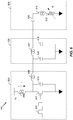
- FIG. 4 is a functional block diagram of a transmitter 404 that may be used in the wireless power transfer system of FIG. 1 , in accordance with exemplary embodiments of the invention.
- the transmitter 404 may include transmit circuitry 406 and a transmit antenna 414.
- the transmit antenna 414 may be the antenna 352 as shown in FIG. 3 .
- Transmit circuitry 406 may provide RF power to the transmit antenna 414 by providing an oscillating signal resulting in generation of energy (e.g., magnetic flux) about the transmit antenna 414.
- Transmitter 404 may operate at any suitable frequency. By way of example, transmitter 404 may operate at the 6.78 MHz ISM band.
- Transmit circuitry 406 may include a fixed impedance matching circuit 409 for matching the impedance of the transmit circuitry 406 (e.g., 50 ohms) to the transmit antenna 414 and a low pass filter (LPF) 408 configured to reduce harmonic emissions to levels to prevent self-jamming of devices coupled to receivers 108 ( FIG. 1 ).
- LPF low pass filter
- Other exemplary embodiments may include different filter topologies, including but not limited to, notch filters that attenuate specific frequencies while passing others and may include an adaptive impedance match, that may be varied based on measurable transmit metrics, such as output power to the antenna 414 or DC current drawn by the driver circuit 424.
- Transmit circuitry 406 further includes a driver circuit 424 configured to drive an RF signal as determined by an oscillator 423.
- the transmit circuitry 406 may be comprised of discrete devices or circuits, or alternately, may be comprised of an integrated assembly.
- An exemplary RF power output from transmit antenna 414 may be on the order of 2.5 Watts.
- Transmit circuitry 406 may further include a controller 415 for selectively enabling the oscillator 423 during transmit phases (or duty cycles) for specific receivers, for adjusting the frequency or phase of the oscillator 423, and for adjusting the output power level for implementing a communication protocol for interacting with neighboring devices through their attached receivers. It is noted that the controller 415 may also be referred to herein as processor 415. Adjustment of oscillator phase and related circuitry in the transmission path may allow for reduction of out of band emissions, especially when transitioning from one frequency to another.
- the transmit circuitry 406 may further include a load sensing circuit 416 for detecting the presence or absence of active receivers in the vicinity of the near-field generated by transmit antenna 414.
- a load sensing circuit 416 monitors the current flowing to the driver circuit 424, that may be affected by the presence or absence of active receivers in the vicinity of the field generated by transmit antenna 414 as will be further described below. Detection of changes to the loading on the driver circuit 424 are monitored by controller 415 for use in determining whether to enable the oscillator 423 for transmitting energy and to communicate with an active receiver. As described more fully below, a current measured at the driver circuit 424 may be used to determine whether an invalid device is positioned within a wireless power transfer region of the transmitter 404.
- the transmit antenna 414 may be implemented with a Litz wire or as an antenna strip with the thickness, width and metal type selected to keep resistive losses low.
- the transmit antenna 414 may generally be configured for association with a larger structure such as a table, mat, lamp or other less portable configuration. Accordingly, the transmit antenna 414 generally may not need "turns" in order to be of a practical dimension.
- An exemplary implementation of a transmit antenna 414 may be "electrically small” (i.e., fraction of the wavelength) and tuned to resonate at lower usable frequencies by using capacitors to define the resonant frequency.
- the transmitter 404 may gather and track information about the whereabouts and status of receiver devices that may be associated with the transmitter 404.
- the transmit circuitry 406 may include a presence detector 480, an enclosed detector 460, or a combination thereof, connected to the controller 415 (also referred to as a processor herein).
- the controller 415 may adjust an amount of power delivered by the driver circuit 424 in response to presence signals from the presence detector 480 and the enclosed detector 460.
- the transmitter 404 may receive power through a number of power sources, such as, for example, an AC-DC converter (not shown) to convert conventional AC power present in a building, a DC-DC converter (not shown) to convert a conventional DC power source to a voltage suitable for the transmitter 404, or directly from a conventional DC power source (not shown).
- power sources such as, for example, an AC-DC converter (not shown) to convert conventional AC power present in a building, a DC-DC converter (not shown) to convert a conventional DC power source to a voltage suitable for the transmitter 404, or directly from a conventional DC power source (not shown).
- the presence detector 480 may be a motion detector utilized to sense the initial presence of a device to be charged that is inserted into the coverage area of the transmitter 404. After detection, the transmitter 404 may be turned on and the RF power received by the device may be used to toggle a switch on the Rx device in a pre-determined manner, which in turn results in changes to the driving point impedance of the transmitter 404.
- the presence detector 480 may be a detector capable of detecting a human, for example, by infrared detection, motion detection, or other suitable means.
- the controller 415 may adjust the power output of the transmit antenna 414 to a regulatory level or lower in response to human presence and adjust the power output of the transmit antenna 414 to a level above the regulatory level when a human is outside a regulatory distance from the electromagnetic field of the transmit antenna 414.
- the enclosed detector 460 may also be referred to herein as an enclosed compartment detector or an enclosed space detector
- the enclosed detector 460 may be a device such as a sense switch for determining when an enclosure is in a closed or open state.
- a power level of the transmitter may be increased.
- a method by which the transmitter 404 does not remain on indefinitely may be used.
- the transmitter 404 may be programmed to shut off after a user-determined amount of time. This feature prevents the transmitter 404, notably the driver circuit 424, from running long after the wireless devices in its perimeter are fully charged. This event may be due to the failure of the circuit to detect the signal sent from either the repeater or the receive antenna 218 that a device is fully charged.
- the transmitter 404 automatic shut off feature may be activated only after a set period of lack of motion detected in its perimeter. The user may be able to determine the inactivity time interval, and change it as desired. As a non-limiting example, the time interval may be longer than that needed to fully charge a specific type of wireless device under the assumption of the device being initially fully discharged.
- FIG. 5 is a functional block diagram of a receiver 508 that may be used in the wireless power transfer system of FIG. 1 , in accordance with exemplary embodiments of the invention.
- the receiver 508 includes receive circuitry 510 that may include a receive antenna 518. Receiver 508 further couples to device 550 for providing received power thereto. It should be noted that receiver 508 is illustrated as being external to device 550 but may be integrated into device 550. Energy may be propagated wirelessly to receive antenna 518 and then coupled through the rest of the receive circuitry 510 to device 550.
- the charging device may include devices such as mobile phones, portable music players, laptop computers, tablet computers, computer peripheral devices, communication devices (e.g., Bluetooth devices), digital cameras, hearing aids (an other medical devices), and the like.
- Receive antenna 518 may be tuned to resonate at the same frequency, or within a specified range of frequencies, as transmit antenna 414 ( FIG. 4 ). Receive antenna 518 may be similarly dimensioned with transmit antenna 414 or may be differently sized based upon the dimensions of the associated device 550.
- device 550 may be a portable electronic device having diametric or length dimension smaller than the diameter or length of transmit antenna 414.
- receive antenna 518 may be implemented as a multi-turn coil in order to reduce the capacitance value of a tuning capacitor (not shown) and increase the receive coil's impedance.
- receive antenna 518 may be placed around the substantial circumference of device 550 in order to maximize the antenna diameter and reduce the number of loop turns (i.e., windings) of the receive antenna 518 and the inter-winding capacitance.
- Receive circuitry 510 may provide an impedance match to the receive antenna 518.
- Receive circuitry 510 includes power conversion circuitry 506 for converting a received RF energy source into charging power for use by the device 550.
- Power conversion circuitry 506 includes an RF-to-DC converter 520 and may also include a DC-to-DC converter 522.
- RF-to-DC converter 520 rectifies the RF energy signal received at receive antenna 518 into a non-alternating power with an output voltage represented by V rect .
- the DC-to-DC converter 522 (or other power regulator) converts the rectified RF energy signal into an energy potential (e.g., voltage) that is compatible with device 550 with an output voltage and output current represented by V out and I out .
- Various RF-to-DC converters are contemplated, including partial and full rectifiers, regulators, bridges, doublers, as well as linear and switching converters.
- Receive circuitry 510 may further include switching circuitry 512 for connecting receive antenna 518 to the power conversion circuitry 506 or alternatively for disconnecting the power conversion circuitry 506. Disconnecting receive antenna 518 from power conversion circuitry 506 not only suspends charging of device 550, but also changes the "load” as “seen” by the transmitter 404 ( FIG. 2 ).
- transmitter 404 includes load sensing circuit 416 that may detect fluctuations in the bias current provided to transmitter driver circuit 424. Accordingly, transmitter 404 has a mechanism for determining when receivers are present in the transmitter's near-field.
- a receiver 508 When multiple receivers 508 are present in a transmitter's near-field, it may be desirable to time-multiplex the loading and unloading of one or more receivers to enable other receivers to more efficiently couple to the transmitter.
- a receiver 508 may also be cloaked in order to eliminate coupling to other nearby receivers or to reduce loading on nearby transmitters. This "unloading" of a receiver is also known herein as a “cloaking.”
- this switching between unloading and loading controlled by receiver 508 and detected by transmitter 404 may provide a communication mechanism from receiver 508 to transmitter 404 as is explained more fully below.
- a protocol may be associated with the switching that enables the sending of a message from receiver 508 to transmitter 404.
- a switching speed may be on the order of 100 ⁇ sec.
- communication between the transmitter 404 and the receiver 508 refers to a device sensing and charging control mechanism, rather than conventional two-way communication (i.e., in band signaling using the coupling field).
- the transmitter 404 may use on/off keying of the transmitted signal to adjust whether energy is available in the near-field.
- the receiver may interpret these changes in energy as a message from the transmitter 404.
- the receiver 508 may use tuning and de-tuning of the receive antenna 518 to adjust how much power is being accepted from the field. In some cases, the tuning and de-tuning may be accomplished via the switching circuitry 512.
- the transmitter 404 may detect this difference in power used from the field and interpret these changes as a message from the receiver 508. It is noted that other forms of modulation of the transmit power and the load behavior may be utilized.
- Receive circuitry 510 may further include signaling detector and beacon circuitry 514 used to identify received energy fluctuations that may correspond to informational signaling from the transmitter to the receiver. Furthermore, signaling and beacon circuitry 514 may also be used to detect the transmission of a reduced RF signal energy (i.e., a beacon signal) and to rectify the reduced RF signal energy into a nominal power for awakening either un-powered or power-depleted circuits within receive circuitry 510 in order to configure receive circuitry 510 for wireless charging.
- a reduced RF signal energy i.e., a beacon signal
- Receive circuitry 510 further includes processor 516 for coordinating the processes of receiver 508 described herein including the control of switching circuitry 512 described herein. Cloaking of receiver 508 may also occur upon the occurrence of other events including detection of an external wired charging source (e.g., wall/USB power) providing charging power to device 550.
- Processor 516 in addition to controlling the cloaking of the receiver, may also monitor beacon circuitry 514 to determine a beacon state and extract messages sent from the transmitter 404. Processor 516 may also adjust the DC-to-DC converter 522 for improved performance.
- FIG. 6 is a schematic diagram of a portion of transmit circuitry 600 that may be used in the transmit circuitry 406 of FIG. 4 .
- the transmit circuitry 600 may include a driver circuit 624 as described above in FIG. 4 .
- the driver circuit 624 may be a switching amplifier that may be configured to receive a square wave and output a sine wave to be provided to the transmit circuit 650. In some cases the driver circuit 624 may be referred to as an amplifier circuit.
- the driver circuit 624 is shown as a class E amplifier, however, any suitable driver circuit 624 may be used in accordance with embodiments of the invention.
- the driver circuit 624 may be driven by an input signal 602 from an oscillator 423 as shown in FIG. 4 .
- the driver circuit 624 may also be provided with a drive voltage V D that is configured to control the maximum power that may be delivered through a transmit circuit 650.
- the transmit circuitry 600 may include a filter circuit 626.
- the filter circuit 626 may be a three pole (capacitor 634, inductor 632, and capacitor 636) low pass filter circuit 626.
- the signal output by the filter circuit 626 may be provided to a transmit circuit 650 comprising an antenna 614.
- the transmit circuit 650 may include a series resonant circuit having a capacitance 620 and inductance (e.g., that may be due to the inductance or capacitance of the antenna or to an additional capacitor component) that may resonate at a frequency of the filtered signal provided by the driver circuit 624.
- the load of the transmit circuit 650 may be represented by the variable resistor 622.
- the load may be a function of a wireless power receiver 508 that is positioned to receive power from the transmit circuit 650.
- a size of a transmit coil such as the transmit antennas 114, 214, and/or 414, in order to accommodate a large device because this may extend a coverage area of a wireless field such that safety becomes an issue.
- the transmit coil is larger than the receive coil (e.g., receive antenna 118, 218, and/or 518)
- the receive coil e.g., receive antenna 118, 218, and/or 518
- a transmitter such as the transmitter 404, includes two or more transmit coils that each generate a wireless field.
- a transmitter that includes two or more transmit coils is described in greater detail below with respect to FIGS. 7-12 .
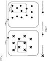
- FIG. 7 is a diagram illustrating the layout of a first transmit coil 708A and a second transmit coil 708B in a wireless power transfer system, such as the wireless power transfer system 100 of FIG. 1 .
- the transmit antenna 414 of FIG. 4 may include the first transmit coil 708A and the second transmit coil 708B.
- a first receive coil 716A and a second receive coil 716B may be located in close proximity to the first transmit coil 708A and the second transmit coil 708B.
- the first receive coil 716A corresponds with a first receive antenna 518 (e.g., a first receiver 508) and the second receive coil 716B corresponds with a second receive antenna 518 (e.g., a second receiver 508).
- a first receive antenna 518 e.g., a first receiver 508
- the second receive coil 716B corresponds with a second receive antenna 518 (e.g., a second receiver 508).
- the wireless power transfer system described herein may apply to any application involving the wireless transfer of energy (e.g., charging mobile devices, electric vehicles, etc.).
- the first transmit coil 708A and the second transmit coil 708B may each be excited at or near their resonant frequency by the transmit circuitry 406.
- the first transmit coil 708A may generate a first wireless field and the second transmit coil 708B may generate a second wireless field.
- the direction of flux through each of the first transmit coil 708A and the second transmit coil 708B is illustrated in FIG. 7 .
- a direction of the wireless field may flow in through the first transmit coil 708A (e.g., the direction of flux is into the page) and a direction of the wireless field may flow out through the second transmit coil 708B (e.g., the direction of flux is out of the page toward the reader).
- the direction of current in the first transmit coil 708A may be counterclockwise and the direction of current in the second transmit coil 708B may be clockwise.
- the first receive coil 716A may overlap the first wireless field generated by the first transmit coil 708A.
- the second receive coil 716B may overlap the second wireless field generated by the second transmit coil 708B.
- the controller 415 may be coupled to the first transmit coil 708A and the second transmit coil 708B (e.g., directly, not shown, or indirectly).
- the controller 415 may be configured to control or adjust the first transmit coil 708A and/or the second transmit coil 708B such that either or both transmit coils 708A and 708B wirelessly transfer energy to the first receive coil 716A, the second receive coil 716B, and/or other receive coils via the first wireless field and/or the second wireless field.
- the controller 415 may control the amount of AC or DC power used to excite the first transmit coil 708A and/or the second transmit coil 708B.
- another controller may be coupled to the first transmit coil 708A and/or the second transmit coil 708B to control or adjust the transmit coils 708A and/or 708B.
- the first transmit coil 708A and the second transmit coil 708B are organized in a side-by-side configuration (e.g., spatially separated). In other embodiments, not shown, a third transmit coil overlaps or is located next to the first transmit coil 708A and the second transmit coil 708B.
- first transmit coil 708A and the second transmit coil 708B are similar or substantially identical to each other.
- first transmit coil 708A and the second transmit coil 708B may be composed of similar or the same materials and may have similar or the same characteristics.
- a magnetic shield (e.g., magnetic shield 854 described below with respect to FIG. 8B ) may be placed under or on the bottom of the first transmit coil 708A and/or the second transmit coil 708B.
- a magnetic shield (e.g., magnetic shield 852 described below with respect to FIG. 8B ) may be placed over or on top of the receive coils 716A and/or 716B and/or other receive coils.
- the magnetic shields may be configured to prevent or reduce the leaking of energy that is transferred wirelessly.
- the magnetic shields may be formed using a ferrite material.
- the transmitter 404 may include at least two operation modes for transferring energy wirelessly to the receiver 508.
- the first transmit coil 708A and the second transmit coil 708B (and any other transmit coils present in the transmitter 404) are activated and configured to individually transfer at least a portion of the energy wirelessly to a receiver (e.g., the first receive coil 716A and/or the second receive coil 716B).
- the first transmit coil 708A may transmit a first amount of energy wirelessly to the receiver.
- the second transmit coil 708B independently of the first transmit coil 708A, may transmit a second amount of energy wirelessly to the receiver.
- the first transmit coil 708A and the second transmit coil 708B may transmit the energy concurrently or non-concurrently.
- the first transmit coil 708A and/or the second transmit coil 708B may be activated based on the presence of a chargeable device (e.g., the first receive coil 716A and/or the second receive coil 716B) in the energy transfer region (e.g., charging region) of the first transmit coil 708A and/or the second transmit coil 708B.
- a chargeable device e.g., the first receive coil 716A and/or the second receive coil 716B
- an energy transfer region e.g., charging region
- the first transmit coil 708A and the second transmit coil 708B are individually activated.
- the first transmit coil 708A and/or the second transmit coil 708B may be activated based on the presence of the first receive coil 716A or the second receive coil 716B in an energy transfer region of one or both of the transmit coils 708A and 708B.
- the first transmit coil 708A may transfer energy wirelessly to a receive coil (e.g., the first receive coil 716A or the second receive coil 716B) via the first wireless field.
- the second transmit coil 708B may transfer energy wirelessly to the receive coil (e.g., the receive coil 716A or the receive coil 716B) via the second wireless field.
- the first wireless field and the second wireless field may be substantially uncoupled wireless fields.
- the first transmit coil 708A and the second transmit coil 708B each may be independently activated, based on their ability to deliver energy to the receive coil.
- one of the first transmit coil 708A and the second transmit coil 708B is activated.
- the activated transmit coil 708A or 708B may transfer energy wirelessly to a receive coil (e.g., the first receive coil 716A or the second receive coil 716B).
- the transmit coil 708A or 708B that was activated may be activated based on the presence of the first receive coil 716A or the second receive coil 716B in an energy transfer region of the activated transmit coil 708A or 708B.
- the transmit coil 708A or 708B that was not activated to transfer energy wirelessly to the receive coil may be activated to transfer energy wirelessly to another receiver (e.g., the second receive coil 716B or the first receive coil 716A) if, for example, the another receiver is present in the energy transfer region of the transmit coil 708A or 708B that was not initially activated.
- the first wireless field and the second wireless field may again be substantially uncoupled wireless fields.
- the first transmit coil 708A and the second transmit coil 708B each transmit energy wirelessly to different receive coils.
- the first transmit coil 708A and the second transmit coil 708B are activated and configured to jointly transfer energy wirelessly to the receiver.
- the first transmit coil 708A and the second transmit coil 708B may be activated based on the presence of the first receive coil 716A or the second receive coil 716B in an energy transfer region of one or both of the transmit coils 708A and 708B.
- the first transmit coil 708A and the second transmit coil 708B may together transmit a determined amount of energy wirelessly to the receiver.
- the first transmit coil 708A and the second transmit coil 708B may each contribute some or all of the determined amount of energy wirelessly transmitted to the receiver.
- a larger amount of power may be output in the second operation mode than in the first operation mode.
- the second operation mode is described in greater detail below with respect to FIGS. 8A-B .
- FIG. 8A is a diagram illustrating a top view 800 of two transmit coils transferring energy wirelessly to a dual-loop receive coil 816A and 816B for charging purposes.
- the first transmit coil is the first transmit coil 708A and the second transmit coil is the second transmit coil 708B.
- the first receive coil 816A and the second receive coil 816B correspond with the same receiver (e.g., the receiver 508 includes two receive antennas 518).
- the receive coils 816A and/or 816B may be located in close proximity to the first transmit coil 708A and/or the second transmit coil 708B.
- the receive coils 816A and/or 816B may overlap the first wireless field generated by the first transmit coil 708A and/or the second wireless field generated by the second transmit coil 708B.
- the direction of current in the first transmit coil 708A may be counterclockwise and the direction of current in the second transmit coil 708B may be clockwise. More precisely, since the current in the first transmit coil 708A and in the second transmit coil 708B is an alternating current (AC) signal, the current in the transmit coils 708A and 708B may be in opposition of phase. Therefore, the direction of current in the first receive coil 816A may be clockwise and the direction of current in the second receive coil 816B may be counterclockwise. More precisely, since the current in the first receive coil 816A and in the second receive coil 816B is an AC signal, the current in the receive coils 816A and 816B may be in opposition of phase.
- AC alternating current
- FIG. 8B is a diagram illustrating a side view 850 of two transmit coils transferring energy wirelessly to a dual-loop receive coil 816A and 816B for charging purposes.
- the first transmit coil is the first transmit coil 708A and the second transmit coil is the second transmit coil 708B.
- the first receive coil 816A and the second receive coil 816B correspond with the same receiver (e.g., the receiver 508 includes two receive antennas 518).
- the receive coils 816A and/or 816B may be located in close proximity to the first transmit coil 708A and/or the second transmit coil 708B.
- the receive coils 816A and/or 816B may overlap the first wireless field generated by the first transmit coil 708A and/or the second wireless field generated by the second transmit coil 708B.
- a magnetic shield 852 may be placed over or on top of the receive coils 816A and 816B.
- a magnetic shield 854 may be placed under or on the bottom of the first transmit coil 708A and the second transmit coil 708B.
- the magnetic shields 852 and/or 854 may be formed with a ferrite material.
- the magnetic shields 852 and 854 may serve to prevent or reduce the leaking of energy that is transferred wirelessly.
- the first transmit coil 708A and the second transmit coil 708B are strongly coupled and there is substantially little energy leakage between the transmitter 404 and the receiver 508.
- the first transmit coil 708A and the second transmit coil 708B may be configured to generate the first and second wireless fields such that the fluxes of the two wireless fields have relatively opposite phases. With the relatively opposite phases, the flux lines of the two wireless fields may be continuous and exist in closed loops.
- the first receive coil 816A and the second receive coil 816B may be electrically connected in series to form an equivalent single receive coil, by connecting the proper terminals, so that the current flow has the same phase.
- a controller such as the controller 415, is configured to select and/or switch between the two operation modes described herein.
- the controller 415 may be configured to do the selecting and/or switching in order to enable the efficient and/or safe wireless transfer of power from the transmitter 404 to the receiver 508.
- the controller 415 is configured to measure a displacement between the transmitter 404 (e.g., the first transmit coil 708A and/or the second transmit coil 708B) and the receiver 508 (e.g., the receive coils 716A, 716B, 816A, and/or 816B).
- the transmitter 404 e.g., the first transmit coil 708A and/or the second transmit coil 708B
- the receiver 508 e.g., the receive coils 716A, 716B, 816A, and/or 816B.
- the controller 415 may be configured to activate one or both of the first transmit coil 708A and the second transmit coil 708B (e.g., set a current phase and/or a current power level of the first transmit coil 708A and/or the second transmit coil 708B) such that a level of the energy wirelessly transferred from the first transmit coil 708A and/or the second transmit coil 708B to the receive coil 716A, 716B, 816A, or 816B is sufficient to charge or power a load.
- the controller 415 may be configured to activate one or both of the first transmit coil 708A and the second transmit coil 708B in the first operation mode and/or the second operation mode.
- the controller 415 is configured to measure a level of coupling between each of the first transmit coil 708A and the second transmit coil 708B and the receive coil 716A, 716B, 816A, or 816B during the first operation mode. In other embodiments, the controller 415 is configured to measure a level of coupling between the first transmit coil 708A and the second transmit coil 708B during the second operation mode. In further embodiments, the controller 415 is configured to measure a level of energy leakage during the first operation mode and/or the second operation mode.
- the controller 415 may be configured to select one of the first operation mode or the second operation mode to transfer energy wirelessly from the first transmit coil 708A and/or the second transmit coil 708B and the receive coils 716A, 716B, 816A, and/or 816B.
- the controller 415 is configured to monitor at least one parameter.
- the parameters may include a position of the receiver 508, a position of a receive coil 716A, 716B, 816A, or 816B, the level of energy leakage (e.g., of the energy wirelessly transmitted), the coupling between the first transmit coil 708A and the second transmit coil 708B, and/or the coupling between the first transmit coil 708A and/or the second transmit coil 708B and a receive coil 716A, 716B, 816A, and/or 816B.
- the controller 415 may be configured to adjust the phase and/or power level of the first transmit coil 708A and/or the second transmit coil 708B (e.g., switch between the first operation mode and the second operation mode). For example, the controller 415 may be configured to switch between the first operation mode and the second operation mode at least based in part on whether the monitored parameter(s) exceeds a threshold.
- sensors, mechanical constraints, mechanical alignments, and/or the like may be included in a wireless power transfer system, such as the wireless power transfer system 100, to assist in determining the appropriate operation mode.
- the transmitter 404 may include a communication module configured to establish a communication link between the transmitter 404 and the receiver 508.
- the transmitter 404 and the receiver 508 may communicate data and/or information via antennas separate from the transmit coils and receive coils described herein.
- the transmitter 404 and the receiver 508 may communicate data and/or information via the transmit coils and receive coils described herein.
- At least two types of information may be transmitted between the transmitter 404 and the receiver 508 via the communication link.
- the first type of information may include information related to wireless energy transfer capabilities, such as relative displacement, antenna size (e.g., coil size), and/or expected wireless power.
- the first type of information may be communicated prior to or at the start of the wireless transfer of energy.
- the second type of information may include information related to energy transfer status updates, such as coupling parameters, energy leakage, and/or displacement.
- the second type of information may be communicated during the wireless transfer of energy.
- the various embodiments described herein for the wireless transfer of energy or power may be implemented in instances where more than two transmit coils are present.
- the transmitter 404 may include three transmit antennas 414, as described below with respect to FIG. 9 , or four transmit antennas 414, as described below with respect to FIG. 10 .
- FIGS. 9 and 10 illustrate the transmit antennas 414 as being circular in shape, this is merely exemplary as the transmit antennas 414 may be in the form of any shape. Such shape may be based on field distribution requirements.
- FIG. 9 is a diagram illustrating a top view 900 and a side view 950 of a first transmit coil 908A, a second transmit coil 908B, and a third transmit coil 908C in a wireless power transfer system, such as the wireless power transfer system 100 of FIG. 1 .
- the transmit coils 908A, 908B, and/or 908C may be positioned in a side-by-side configuration (e.g., spatially separated).
- the transmit coils 908A, 908B, and/or 908C border each other and are equidistant or nearly equidistant from each other.
- one or more of the transmit coils 908A, 908B, and/or 908C overlap.
- the first transmit coil 908A may be configured to generate a first wireless field
- the second transmit coil 908B may be configured to generate a second wireless field
- the third transmit coil 908C may be configured to generate a third wireless field.
- the transmit coils 908A, 908B, and/or 908C may generate a field direction that alternates in each subsequent coil.
- the transmit coil 908B may have a phase offset of 120 degrees as compared to the transmit coil 908A.
- the transmit coil 908C may have a phase offset of 120 degrees as compared to the transmit coil 908B
- the transmit coil 908A may have a phase offset of 120 degrees as compared to the transmit coil 908C.
- Such a phase offset may create a total flux of zero along the center axis (e.g., an axis that extends through the center of the combination of transmit coils 908A, 908B, and 908C), and a sensing coil placed around the combination of transmit coils 908A, 908B, and 908C may allow for more accurate positioning of a receiver (e.g., the receiver 508) to minimize flux leakage.
- the transmit antenna 414 may include one or more of the transmit coils 908A, 908B, and/or 908C.
- the receive antenna 518 may include the receive coil 916, which may be implemented by electrically connecting multiple coils in series, as described above with respect to receive coils 816A and 816B.
- the controller 415 may be coupled directly or indirectly to the transmit coils 908A, 908B, and/or 908C.
- the transmit coils 908A, 908B, and/or 908C may be operated in the first operation mode or the second operation mode by the controller 415 as described herein.
- the controller 415 may be configured to activate one or more of the transmit coils 908A, 908B, and/or 908C (e.g., set a current phase and/or a current power level of the transmit coils 908A, 908B, and/or 908C) such that a level of the energy wirelessly transferred from the transmit coils 908A, 908B, and/or 908C to the receive coil 916 and/or any other receive coil present within an energy transfer region of the transmit coils 908A, 908B, and/or 908C is sufficient to charge or power a load.
- the transmit coils 908A, 908B, and/or 908C e.g., set a current phase and/or a current power level of the transmit coils 908A, 908B, and/or 908C
- the controller 415 may be configured to individually set a current phase and/or a current power level of the transmit coils 908A, 908B, and/or 908C such that the energy is wirelessly transferred separately from the transmit coils 908A, 908B, and/or 908C to the receive coil 916 and/or any other receive coil present within an energy transfer region of the transmit coils 908A, 908B, and/or 908C.
- the controller 415 may be configured to jointly set a current phase and/or a current power level of the transmit coils 908A, 908B, and/or 908C such that the energy is wirelessly transferred collectively from the transmit coils 908A, 908B, and/or 908C to the receive coil 916 and/or any other receive coil present within an energy transfer region of the transmit coils 908A, 908B, and/or 908C.
- the controller 415 may be configured to measure a level of coupling between the receive coil 916 and each of the transmit coils 908A, 908B, and/or 908C, a level of coupling between the transmit coils 908A, 908B, and/or 908C, and/or a level of energy leakage during different operation modes.
- the controller 415 may be configured to select one of the different operations modes to transfer energy wirelessly from the transmit coils 908A, 908B, and/or 908C to the receive coil 916 and/or any other receive coil present in an energy transfer region of the transmit coils 908A, 908B, and/or 908C.
- FIG. 10 is a diagram illustrating a top view 1000 and a side view 1050 of a first transmit coil 1008A, a second transmit coil 1008B, a third transmit coil 1008C, and a fourth transmit coil 1008D in a wireless power transfer system, such as the wireless power transfer system 100 of FIG. 1 .
- the transmit coils 1008A, 1008B, 1008C, and/or 1008D may be positioned in a side-by-side configuration.
- the transmit coils 1008A, 1008B, 1008C, and/or 1008D border each other and are equidistant or nearly equidistant from each other.
- one or more of the transmit coils 1008A, 1008B, 1008C, and/or 1008D overlap.
- the first transmit coil 1008A may be configured to generate a first wireless field
- the second transmit coil 1008B may be configured to generate a second wireless field
- the third transmit coil 1008C may be configured to generate a third wireless field
- the fourth transmit coil 1008D may be configured to generate a fourth wireless field.
- the transmit coil 1008B may have a phase offset of ninety degrees as compared to the transmit coil 1008A.
- the transmit coil 1008C may have a phase offset of ninety degrees as compared to the transmit coil 1008B
- the transmit coil 1008D may have a phase offset of ninety degrees as compared to the transmit coil 1008C
- the transmit coil 1008A may have a phase offset of ninety degrees as compared to the induction coil 1008D.
- the transmit antenna 414 may include one or more of the transmit coils 1008A, 1008B, 1008C, and/or 1008D.
- the receive antenna 518 may include the receive coil 1016, which may be implemented by electrically connecting multiple coils in series, as described above with respect to receive coils 816A and 816B.
- the controller 415 may be coupled directly or indirectly to the transmit coils 1008A, 1008B, 1008C, and/or 1008D.
- the transmit coils 1008A, 1008B, 1008C, and/or 1008D may be operated in the first operation mode or the second operation mode by the controller 415 as described herein.
- the controller 415 may be configured to activate one or more of the transmit coils 1008A, 1008B, 1008C, and/or 1008D (e.g., set a current phase and/or a current power level of the transmit coils 1008A, 1008B, 1008C, and/or 1008D) such that a level of the energy wirelessly transferred from the transmit coils 1008A, 1008B, 1008C, and/or 1008D to the receive coil 1016 and/or any other receive coil present within an energy transfer region of the transmit coils 1008A, 1008B, 1008C, and/or 1008D is sufficient to charge or power a load.
- the transmit coils 1008A, 1008B, 1008C, and/or 1008D e.g., set a current phase and/or a current power level of the transmit coils 1008A, 1008B, 1008C, and/or 1008D
- the controller 415 may be configured to individually set a current phase and/or a current power level of the transmit coils 1008A, 1008B, 1008C, and/or 1008D such that the energy is wirelessly transferred separately from the transmit coils 1008A, 1008B, 1008C, and/or 1008D to the receive coil 1016 and/or any other receive coil present within an energy transfer region of the transmit coils 1008A, 1008B, 1008C, and/or 1008D.
- the controller 415 may be configured to jointly set a current phase and/or a current power level of the transmit coils 1008A, 1008B, 1008C, and/or 1008D such that the energy is wirelessly transferred collectively from the transmit coils 1008A, 1008B, 1008C, and/or 1008D to the receive coil 1016 and/or any other receive coil present within an energy transfer region of the transmit coils 1008A, 1008B, 1008C, and/or 1008D.
- the controller 415 may be configured to measure a level of coupling between the receive coil 1016 and each of the transmit coils 1008A, 1008B, 1008C, and/or 1008D, a level of coupling between the transmit coils 1008A, 1008B, 1008C, and/or 1008D, and/or a level of energy leakage during different operation modes.
- the controller 415 may be configured to select one of the different operations modes to transfer energy wirelessly from the transmit coils 1008A, 1008B, 1008C, and/or 1008D to the receive coil 1016 and/or any other receive coil present in an energy transfer region of the transmit coils 1008A, 1008B, 1008C, and/or 1008D.
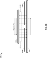
- FIG. 11 is a flowchart of an exemplary method 1100 for transferring energy wirelessly.
- the steps in flowchart 1100 may be performed by the transmitter 404.
- the method of flowchart 1100 is described herein with reference to a particular order, in various embodiments, blocks herein may be performed in a different order, or omitted, and additional blocks may be added.
- the method of flowchart 1100 may be implemented in any device that may be configured to charge or supply power to another device via the wireless transfer of power.
- a first wireless field is generated by a first transmit antenna when the at least one receiver is in an energy transfer region of the first transmit antenna.
- the first transmit antenna is the first transmit coil 708A.
- current in the first transmit antenna flows in a first direction when the first transmit antenna is activated.
- the at least one receive antenna is one of the receive coils 716A, 716B, 816A, 816B, 916, and/or 1016.
- a second wireless field is generated by a second transmit antenna spatially separated from the first transmit antenna when the at least one receiver is in an energy transfer region of the second transmit antenna.
- current in the second transmit antenna flows in a second direction different than the first direction when the second transmit antenna is activated.
- At block 1106, at least one of the first transmit antenna or the second transmit antenna is activated based on whether the at least one receiver is in an energy transfer region of one or both of the first wireless field and the second wireless field.
- FIG. 12 is a functional block diagram of a transmitter 1200, in accordance with an exemplary embodiment.
- Transmitter 1200 comprises means 1202, means 1204, means 1206, and means 1208 for the various actions discussed with respect to FIGS. 1-10 .
- the transmitter 1200 includes means 1202 for generating a first wireless field when the at least one receiver is in an energy transfer region of the means for generating the first wireless field.
- means 1202 for generating a first wireless field when the at least one receiver is in an energy transfer region of the means for generating the first wireless field may be configured to perform one or more of the functions discussed above with respect to block 1102.
- the transmitter 1200 includes means 1204 for generating a second wireless field when the at least one receiver is in an energy transfer region of the means for generating the second wireless field.
- means 1204 for generating a second wireless field when the at least one receiver is in an energy transfer region of the means for generating the second wireless field may be configured to perform one or more of the functions discussed above with respect to block 1104.
- the transmitter 1200 further includes means 1206 for activating at least one of the means for generating the first wireless field or the means for generating the second wireless field based on whether the at least one receiver is in an energy transfer region of one or both of the first wireless field and the second wireless field.
- means 1206 for activating at least one of the means for generating the first wireless field or the means for generating the second wireless field based on whether the at least one receiver is in an energy transfer region of one or both of the first wireless field and the second wireless field may be configured to perform one or more of the functions discussed above with respect to block 1106.
- the transmitter 1200 further includes means 1208 for controlling, when both the means for generating the first wireless field and the means for generating the second wireless field are activated, whether the means for generating the first wireless field and the means for generating the second wireless field independently transfer energy wirelessly to a same receiver via the first and second wireless fields, whether the means for generating the first wireless field and the means for generating the second wireless field jointly transfer energy wirelessly to the same receiver via the first and second wireless fields, or whether the means for generating the first wireless field and the means for generating the second wireless field transfer energy wirelessly to different receivers via the first and second wirelessly fields.
- means 1208 for controlling, when both the means for generating the first wireless field and the means for generating the second wireless field are activated, whether the means for generating the first wireless field and the means for generating the second wireless field independently transfer energy wirelessly to a same receiver via the first and second wireless fields, whether the means for generating the first wireless field and the means for generating the second wireless field jointly transfer energy wirelessly to the same receiver via the first and second wireless fields, or whether the means for generating the first wireless field and the means for generating the second wireless field transfer energy wirelessly to different receivers via the first and second wirelessly fields may be configured to perform one or more of the functions discussed above with respect to block 1108.
- the various operations of methods described above may be performed by any suitable means capable of performing the operations, such as various hardware and/or software component(s), circuits, and/or module(s). Generally, any operations illustrated in the Figures may be performed by corresponding functional means capable of performing the operations.
- the means for generating a first wireless field comprises the first transmit coil 708A.
- the means for generating a second wireless field comprises the second transmit coil 708B.
- the means for activating and the means for controlling comprise the controller 415.
- Information and signals may be represented using any of a variety of different technologies and techniques.
- data, instructions, commands, information, signals, bits, symbols, and chips that may be referenced throughout the above description may be represented by voltages, currents, electromagnetic waves, magnetic fields or particles, optical fields or particles, or any combination thereof.
- DSP Digital Signal Processor
- ASIC Application Specific Integrated Circuit
- FPGA Field Programmable Gate Array
- a general purpose processor may be a microprocessor, but in the alternative, the processor may be any conventional processor, controller, microcontroller, or state machine.
- a processor may also be implemented as a combination of computing devices, e.g., a combination of a DSP and a microprocessor, a plurality of microprocessors, one or more microprocessors in conjunction with a DSP core, or any other such configuration.
- a software module may reside in Random Access Memory (RAM), flash memory, Read Only Memory (ROM), Electrically Programmable ROM (EPROM), Electrically Erasable Programmable ROM (EEPROM), registers, hard disk, a removable disk, a CD ROM, or any other form of storage medium known in the art.
- RAM Random Access Memory
- ROM Read Only Memory
- EPROM Electrically Programmable ROM
- EEPROM Electrically Erasable Programmable ROM
- registers hard disk, a removable disk, a CD ROM, or any other form of storage medium known in the art.
- a storage medium is coupled to the processor such that the processor can read information from, and write information to, the storage medium.
- the storage medium may be integral to the processor.
- Disk and disc includes compact disc (CD), laser disc, optical disc, digital versatile disc (DVD), floppy disk and blu ray disc where disks usually reproduce data magnetically, while discs reproduce data optically with lasers. Combinations of the above should also be included within the scope of computer readable media.
- the processor and the storage medium may reside in an ASIC.
- the ASIC may reside in a user terminal.
- the processor and the storage medium may reside as discrete components in a user terminal.
Description
- The present invention relates generally to wireless power. More specifically, the disclosure is directed to transmitters and receivers in a wireless power transfer system.
- An increasing number and variety of electronic devices are powered via rechargeable batteries. Such devices include mobile phones, portable music players, laptop computers, tablet computers, computer peripheral devices, communication devices (e.g., Bluetooth devices), digital cameras, hearing aids, and the like. While battery technology has improved, battery-powered electronic devices increasingly require and consume greater amounts of power, thereby often requiring recharging. Rechargeable devices are often charged via wired connections through cables or other similar connectors that are physically connected to a power supply. Cables and similar connectors may sometimes be inconvenient or cumbersome and have other drawbacks. Wireless charging systems that are capable of transferring power in free space to be used to charge rechargeable electronic devices or provide power to electronic devices may overcome some of the deficiencies of wired charging solutions. As such, wireless power transfer systems and methods that efficiently and safely transfer power to electronic devices are desirable, see for example
US2011/0156640 . - Various implementations of systems, methods and devices within the scope of the appended claims each have several aspects, no single one of which is solely responsible for the desirable attributes described herein. Without limiting the scope of the appended claims, some prominent features are described herein.
- Details of one or more implementations of the subject matter described in this specification are set forth in the accompanying drawings and the description below. Other features, aspects, and advantages will become apparent from the description, the drawings, and the claims. Note that the relative dimensions of the following figures may not be drawn to scale.
- One aspect of the disclosure provides an apparatus for transferring energy wirelessly to at least one receive antenna of at least one receiver according to
claim 1. The apparatus comprises a first transmit antenna configured to generate a first wireless field when the at least one receiver is in an energy transfer region of the first transmit antenna. The apparatus further comprises a second transmit antenna spatially separated from the first transmit antenna, the second transmit antenna configured to generate a second wireless field when the at least one receiver is in an energy transfer region of the second transmit antenna. The apparatus further comprises a controller operationally coupled to the first transmit antenna and the second transmit antenna and configured to activate at least one of the first transmit antenna or the second transmit antenna based on whether the at least one receiver is in an energy transfer region of one or both of the first wireless field and the second wireless field. The controller may be further configured to control, when both the first transmit antenna and the second transmit antenna are activated, whether the first transmit antenna and the second transmit antenna independently transfer energy wirelessly to a same receiver via the first and second wireless fields, whether the first transmit antenna and the second transmit antenna jointly transfer energy wirelessly to the same receiver via the first and second wireless fields, or whether the first transmit antenna and the second transmit antenna transfer energy wirelessly to different receivers via the first and second wirelessly fields. - Another aspect of the disclosure provides a method of transferring energy wirelessly to at least one receive antenna of at least one receiver according to claim 6. The method comprises generating, by a first transmit antenna, a first wireless field when the at least one receiver is in an energy transfer region of the first transmit antenna. The method further comprises generating, by a second transmit antenna spatially separated from the first transmit antenna, a second wireless field when the at least one receiver is in an energy transfer region of the second transmit antenna. The method further comprises activating at least one of the first transmit antenna or the second transmit antenna based on whether the at least one receiver is in an energy transfer region of one or both of the first wireless field and the second wireless field. The method further comprises controlling, when both the first transmit antenna and the second transmit antenna are activated, whether the first transmit antenna and the second transmit antenna independently transfer energy wirelessly to a same receiver via the first and second wireless fields, whether the first transmit antenna and the second transmit antenna jointly transfer energy wirelessly to the same receiver via the first and second wireless fields, or whether the first transmit antenna and the second transmit antenna transfer energy wirelessly to different receivers via the first and second wirelessly fields.
- Another aspect of the disclosure provides an apparatus for transferring energy wirelessly to at least one receive antenna of at least one receiver. The apparatus comprises means for generating a first wireless field when the at least one receiver is in an energy transfer region of the means for generating the first wireless field. The apparatus further comprises means for generating a second wireless field when the at least one receiver is in an energy transfer region of the means for generating the second wireless field. The apparatus further comprises means for activating at least one of the means for generating the first wireless field or the means for generating the second wireless field based on whether the at least one receiver is in an energy transfer region of one or both of the first wireless field and the second wireless field. The apparatus further comprises means for controlling, when both the means for generating the first wireless field and the means for generating the second wireless field are activated, whether the means for generating the first wireless field and the means for generating the second wireless field independently transfer energy wirelessly to a same receiver via the first and second wireless fields, whether the means for generating the first wireless field and the means for generating the second wireless field jointly transfer energy wirelessly to the same receiver via the first and second wireless fields, or whether the means for generating the first wireless field and the means for generating the second wireless field transfer energy wirelessly to different receivers via the first and second wirelessly fields.
- Another aspect of the disclosure provides a non-transitory computer-readable medium according to claim 11 comprising code that, when executed, causes an apparatus to generate, using a first transmit antenna, a first wireless field when at least one receiver is in an energy transfer region of the first transmit antenna. The medium further comprises code that, when executed, causes an apparatus to generate, using a second transmit antenna spatially separated from the first transmit antenna, a second wireless field when the at least one receiver is in an energy transfer region of the second transmit antenna. The medium further comprises code that, when executed, causes an apparatus to activate at least one of the first transmit antenna or the second transmit antenna based on whether the at least one receiver is in an energy transfer region of one or both of the first wireless field and the second wireless field. The medium further comprises code that, when executed, causes an apparatus to control, when both the first transmit antenna and the second transmit antenna are activated, whether the first transmit antenna and the second transmit antenna independently transfer energy wirelessly to a same receiver via the first and second wireless fields, whether the first transmit antenna and the second transmit antenna jointly transfer energy wirelessly to the same receiver via the first and second wireless fields, or whether the first transmit antenna and the second transmit antenna transfer energy wirelessly to different receivers via the first and second wirelessly fields.
-
-
FIG. 1 is a functional block diagram of an exemplary wireless power transfer system, in accordance with exemplary embodiments of the invention. -
FIG. 2 is a functional block diagram of exemplary components that may be used in the wireless power transfer system ofFIG. 1 , in accordance with various exemplary embodiments of the invention. -
FIG. 3 is a schematic diagram of a portion of transmit circuitry or receive circuitry ofFIG. 2 including a transmit or receive antenna, in accordance with exemplary embodiments of the invention. -
FIG. 4 is a functional block diagram of a transmitter that may be used in the wireless power transfer system ofFIG. 1 , in accordance with exemplary embodiments of the invention. -
FIG. 5 is a functional block diagram of a receiver that may be used in the wireless power transfer system ofFIG. 1 , in accordance with exemplary embodiments of the invention. -
FIG. 6 is a schematic diagram of a portion of transmit circuitry that may be used in the transmit circuitry ofFIG. 4 . -
FIG. 7 is a diagram illustrating the layout of a first transmit coil and a second transmit coil in the wireless power transfer system ofFIG. 1 . -
FIG. 8A is a diagram illustrating a top view of two transmit coils transferring energy wirelessly to a dual-loop receive coil for charging purposes. -
FIG. 8B is a diagram illustrating a side view of two transmit coils transferring energy wirelessly to a dual-loop receive coil for charging purposes. -
FIG. 9 is a diagram illustrating a top view and a side view of a first transmit coil, a second transmit coil, and a third transmit coil in the wireless power transfer system ofFIG. 1 . -
FIG. 10 is a diagram illustrating a top view and a side view of a first transmit coil, a second transmit coil, a third transmit coil, and a fourth transmit coil in the wireless power transfer system ofFIG. 1 . -
FIG. 11 is a flowchart of anexemplary method 800 for transferring energy wirelessly. -
FIG. 12 is a functional block diagram of a transmitter, in accordance with an exemplary embodiment. - The various features illustrated in the drawings may not be drawn to scale. Accordingly, the dimensions of the various features may be arbitrarily expanded or reduced for clarity. In addition, some of the drawings may not depict all of the components of a given system, method or device. Finally, like reference numerals may be used to denote like features throughout the specification and figures.
- The detailed description set forth below in connection with the appended drawings is intended as a description of exemplary embodiments of the invention and is not intended to represent the only embodiments in which the invention may be practiced. The term "exemplary" used throughout this description means "serving as an example, instance, or illustration," and should not necessarily be construed as preferred or advantageous over other exemplary embodiments. The detailed description includes specific details for the purpose of providing a thorough understanding of the exemplary embodiments of the invention. In some instances, some devices are shown in block diagram form.
- Wirelessly transferring power may refer to transferring any form of energy associated with electric fields, magnetic fields, electromagnetic fields, or otherwise from a transmitter to a receiver without the use of physical electrical conductors (e.g., power may be transferred through free space). The power output into a wireless field (e.g., a magnetic field or an electromagnetic field) may be received, captured by, or coupled by a "receiving antenna" to achieve power transfer. It will be understood that, throughout this specification, two components being "coupled" may refer to their interaction through direct or indirect ways, and may further refer to a physically connected (e.g. wired) coupling or a physically disconnected (e.g. wireless) coupling.
-
FIG. 1 is a functional block diagram of an exemplary wirelesspower transfer system 100, in accordance with exemplary embodiments of the invention.Input power 102 may be provided to atransmitter 104 from a power source (not shown) for generating afield 105 for providing energy transfer. Areceiver 108 may couple to thefield 105 and generateoutput power 110 for storing or consumption by a device (not shown) coupled to theoutput power 110. Both thetransmitter 104 and thereceiver 108 are separated by adistance 112. In one exemplary embodiment,transmitter 104 andreceiver 108 are configured according to a mutual resonant relationship. When the resonant frequency ofreceiver 108 and the resonant frequency oftransmitter 104 are substantially the same or very close, transmission losses between thetransmitter 104 and thereceiver 108 are minimal. As such, wireless power transfer may be provided over larger distance in contrast to purely inductive solutions that may require large coils to be very close (e.g., mms). Resonant inductive coupling techniques may thus allow for improved efficiency and power transfer over various distances and with a variety of inductive coil configurations. - The
receiver 108 may receive power when thereceiver 108 is located in anenergy field 105 produced by thetransmitter 104. Thefield 105 corresponds to a region where energy output by thetransmitter 104 may be captured by areceiver 105. In some cases, thefield 105 may correspond to the "near-field" of thetransmitter 104 as will be further described below. Thetransmitter 104 may include a transmit antenna 114 (e.g., a transmit coil) for outputting an energy transmission. Thereceiver 108 further includes a receive antenna 118 (e.g., a receive coil) for receiving or capturing energy from the energy transmission. The near-field may correspond to a region in which there are strong reactive fields resulting from the currents and charges in the transmitantenna 114 that minimally radiate power away from the transmitantenna 114. In some cases the near-field may correspond to a region that is within about one wavelength (or a fraction thereof) of the transmitantenna 114. The transmit and receiveantennas field 105 of the transmitantenna 114 to a receiveantenna 118 rather than propagating most of the energy in an electromagnetic wave to the far field. When positioned within thefield 105, a "coupling mode" may be developed between the transmitantenna 114 and the receiveantenna 118. The area around the transmit and receiveantennas -
FIG. 2 is a functional block diagram of exemplary components that may be used in the wirelesspower transfer system 100 ofFIG. 1 , in accordance with various exemplary embodiments of the invention. Thetransmitter 204 may include transmitcircuitry 206 that may include anoscillator 222, adriver circuit 224, and a filter and matchingcircuit 226. Theoscillator 222 may be configured to generate a signal at a desired frequency, such as 468.75 KHz, 6.78 MHz or 13.56 MHz, that may be adjusted in response to afrequency control signal 223. The oscillator signal may be provided to adriver circuit 224 configured to drive the transmitantenna 214 at, for example, a resonant frequency of the transmitantenna 214. Thedriver circuit 224 may be a switching amplifier configured to receive a square wave from theoscillator 222 and output a sine wave. For example, thedriver circuit 224 may be a class E amplifier. A filter and matchingcircuit 226 may be also included to filter out harmonics or other unwanted frequencies and match the impedance of thetransmitter 204 to the transmitantenna 214. As a result of driving the transmitantenna 214, thetransmitter 204 may wirelessly output power at a level sufficient for charging or powering an electronic device. As one example, the power provided may be for example on the order of 300 milliWatts to 5 Watts to power or charge different devices with different power requirements. Higher or lower power levels may also be provided. - The
receiver 208 may include receivecircuitry 210 that may include amatching circuit 232 and a rectifier and switchingcircuit 234 to generate a DC power output from an AC power input to charge abattery 236 as shown inFIG. 2 or to power a device (not shown) coupled to thereceiver 108. Thematching circuit 232 may be included to match the impedance of the receivecircuitry 210 to the receiveantenna 218. Thereceiver 208 andtransmitter 204 may additionally communicate on a separate communication channel 219 (e.g., Bluetooth, zigbee, cellular, etc). Thereceiver 208 andtransmitter 204 may alternatively communicate via in-band signaling using characteristics of thewireless field 206. - As described more fully below,
receiver 208, that may initially have a selectively disablable associated load (e.g., battery 236), may be configured to determine whether an amount of power transmitted bytransmitter 204 and received byreceiver 208 is appropriate for charging abattery 236. Further,receiver 208 may be configured to enable a load (e.g., battery 236) upon determining that the amount of power is appropriate. In some embodiments, areceiver 208 may be configured to directly utilize power received from a wireless power transfer field without charging of abattery 236. For example, a communication device, such as a near-field communication (NFC) or radio-frequency identification device (RFID may be configured to receive power from a wireless power transfer field and communicate by interacting with the wireless power transfer field and/or utilize the received power to communicate with atransmitter 204 or other devices. -
FIG. 3 is a schematic diagram of a portion of transmitcircuitry 206 or receivecircuitry 210 ofFIG. 2 including a transmit or receiveantenna 352, in accordance with exemplary embodiments of the invention. As illustrated inFIG. 3 , transmit or receivecircuitry 350 used in exemplary embodiments including those described below may include anantenna 352. Theantenna 352 may also be referred to or be configured as a "loop"antenna 352. Theantenna 352 may also be referred to herein or be configured as a "magnetic" antenna or an induction coil. The term "antenna" generally refers to a component that may wirelessly output or receive energy for coupling to another "antenna." The antenna may also be referred to as a coil of a type that is configured to wirelessly output or receive power. As used herein, anantenna 352 is an example of a "power transfer component" of a type that is configured to wirelessly output and/or receive power. Theantenna 352 may be configured to include an air core or a physical core such as a ferrite core (not shown). An aircore loop antenna 352 allows the placement of other components within the core area. In addition, an air core loop may more readily enable placement of the receive antenna 218 (FIG. 2 ) within a plane of the transmit antenna 214 (FIG. 2 ) where the coupled-mode region of the transmit antenna 214 (FIG. 2 ) may be more powerful. - As stated, efficient transfer of energy between the
transmitter 104 andreceiver 108 may occur during matched or nearly matched resonance between thetransmitter 104 and thereceiver 108. However, even when resonance between thetransmitter 104 andreceiver 108 are not matched, energy may be transferred, although the efficiency may be affected. Transfer of energy occurs by coupling energy from thefield 105 of the transmitantenna 214 coil to the receiveantenna 218 residing in the neighborhood where thisfield 105 is established rather than propagating the energy from the transmitantenna 214 into free space. - The resonant frequency of the loop or magnetic antennas is based on the inductance and capacitance. Inductance may be simply the inductance created by the
antenna 352, whereas, capacitance may be added to the antenna's inductance to create a resonant structure at a desired resonant frequency. As a non-limiting example,capacitor 352 andcapacitor 354 may be added to the transmit or receivecircuitry 350 to create a resonant circuit that selects asignal 356 at a resonant frequency. Accordingly, for larger diameter antennas, the size of capacitance needed to sustain resonance may decrease as the diameter or inductance of the loop increases. Furthermore, as the diameter of the antenna increases, the efficient energy transfer area of the near-field may increase. Other resonant circuits formed using other components are also possible. As another non-limiting example, a capacitor may be placed in parallel between the two terminals of theantenna 350. For transmit antennas, a signal 358 with a frequency that substantially corresponds to the resonant frequency of theantenna 352 may be an input to theantenna 352. - In one embodiment, the
transmitter 104 may be configured to output a time varying magnetic field with a frequency corresponding to the resonant frequency of the transmitantenna 114. When the receiver is within thefield 105, the time varying magnetic field may induce a current in the receiveantenna 118. As described above, if the receiveantenna 118 is configured to be resonant at the frequency of the transmitantenna 118, energy may be efficiently transferred. The AC signal induced in the receiveantenna 118 may be rectified as described above to produce a DC signal that may be provided to charge or to power a load. -
FIG. 4 is a functional block diagram of atransmitter 404 that may be used in the wireless power transfer system ofFIG. 1 , in accordance with exemplary embodiments of the invention. Thetransmitter 404 may include transmitcircuitry 406 and a transmitantenna 414. The transmitantenna 414 may be theantenna 352 as shown inFIG. 3 . Transmitcircuitry 406 may provide RF power to the transmitantenna 414 by providing an oscillating signal resulting in generation of energy (e.g., magnetic flux) about the transmitantenna 414.Transmitter 404 may operate at any suitable frequency. By way of example,transmitter 404 may operate at the 6.78 MHz ISM band. - Transmit
circuitry 406 may include a fixedimpedance matching circuit 409 for matching the impedance of the transmit circuitry 406 (e.g., 50 ohms) to the transmitantenna 414 and a low pass filter (LPF) 408 configured to reduce harmonic emissions to levels to prevent self-jamming of devices coupled to receivers 108 (FIG. 1 ). Other exemplary embodiments may include different filter topologies, including but not limited to, notch filters that attenuate specific frequencies while passing others and may include an adaptive impedance match, that may be varied based on measurable transmit metrics, such as output power to theantenna 414 or DC current drawn by thedriver circuit 424. Transmitcircuitry 406 further includes adriver circuit 424 configured to drive an RF signal as determined by anoscillator 423. The transmitcircuitry 406 may be comprised of discrete devices or circuits, or alternately, may be comprised of an integrated assembly. An exemplary RF power output from transmitantenna 414 may be on the order of 2.5 Watts. - Transmit
circuitry 406 may further include acontroller 415 for selectively enabling theoscillator 423 during transmit phases (or duty cycles) for specific receivers, for adjusting the frequency or phase of theoscillator 423, and for adjusting the output power level for implementing a communication protocol for interacting with neighboring devices through their attached receivers. It is noted that thecontroller 415 may also be referred to herein asprocessor 415. Adjustment of oscillator phase and related circuitry in the transmission path may allow for reduction of out of band emissions, especially when transitioning from one frequency to another. - The transmit
circuitry 406 may further include aload sensing circuit 416 for detecting the presence or absence of active receivers in the vicinity of the near-field generated by transmitantenna 414. By way of example, aload sensing circuit 416 monitors the current flowing to thedriver circuit 424, that may be affected by the presence or absence of active receivers in the vicinity of the field generated by transmitantenna 414 as will be further described below. Detection of changes to the loading on thedriver circuit 424 are monitored bycontroller 415 for use in determining whether to enable theoscillator 423 for transmitting energy and to communicate with an active receiver. As described more fully below, a current measured at thedriver circuit 424 may be used to determine whether an invalid device is positioned within a wireless power transfer region of thetransmitter 404. - The transmit
antenna 414 may be implemented with a Litz wire or as an antenna strip with the thickness, width and metal type selected to keep resistive losses low. In a one implementation, the transmitantenna 414 may generally be configured for association with a larger structure such as a table, mat, lamp or other less portable configuration. Accordingly, the transmitantenna 414 generally may not need "turns" in order to be of a practical dimension. An exemplary implementation of a transmitantenna 414 may be "electrically small" (i.e., fraction of the wavelength) and tuned to resonate at lower usable frequencies by using capacitors to define the resonant frequency. - The
transmitter 404 may gather and track information about the whereabouts and status of receiver devices that may be associated with thetransmitter 404. Thus, the transmitcircuitry 406 may include apresence detector 480, anenclosed detector 460, or a combination thereof, connected to the controller 415 (also referred to as a processor herein). Thecontroller 415 may adjust an amount of power delivered by thedriver circuit 424 in response to presence signals from thepresence detector 480 and theenclosed detector 460. Thetransmitter 404 may receive power through a number of power sources, such as, for example, an AC-DC converter (not shown) to convert conventional AC power present in a building, a DC-DC converter (not shown) to convert a conventional DC power source to a voltage suitable for thetransmitter 404, or directly from a conventional DC power source (not shown). - As a non-limiting example, the
presence detector 480 may be a motion detector utilized to sense the initial presence of a device to be charged that is inserted into the coverage area of thetransmitter 404. After detection, thetransmitter 404 may be turned on and the RF power received by the device may be used to toggle a switch on the Rx device in a pre-determined manner, which in turn results in changes to the driving point impedance of thetransmitter 404. - As another non-limiting example, the
presence detector 480 may be a detector capable of detecting a human, for example, by infrared detection, motion detection, or other suitable means. In some exemplary embodiments, there may be regulations limiting the amount of power that a transmitantenna 414 may transmit at a specific frequency. In some cases, these regulations are meant to protect humans from electromagnetic radiation. However, there may be environments where a transmitantenna 414 is placed in areas not occupied by humans, or occupied infrequently by humans, such as, for example, garages, factory floors, shops, and the like. If these environments are free from humans, it may be permissible to increase the power output of the transmitantenna 414 above the normal power restrictions regulations. In other words, thecontroller 415 may adjust the power output of the transmitantenna 414 to a regulatory level or lower in response to human presence and adjust the power output of the transmitantenna 414 to a level above the regulatory level when a human is outside a regulatory distance from the electromagnetic field of the transmitantenna 414. - As a non-limiting example, the enclosed detector 460 (may also be referred to herein as an enclosed compartment detector or an enclosed space detector) may be a device such as a sense switch for determining when an enclosure is in a closed or open state. When a transmitter is in an enclosure that is in an enclosed state, a power level of the transmitter may be increased.
- In exemplary embodiments, a method by which the
transmitter 404 does not remain on indefinitely may be used. In this case, thetransmitter 404 may be programmed to shut off after a user-determined amount of time. This feature prevents thetransmitter 404, notably thedriver circuit 424, from running long after the wireless devices in its perimeter are fully charged. This event may be due to the failure of the circuit to detect the signal sent from either the repeater or the receiveantenna 218 that a device is fully charged. To prevent thetransmitter 404 from automatically shutting down if another device is placed in its perimeter, thetransmitter 404 automatic shut off feature may be activated only after a set period of lack of motion detected in its perimeter. The user may be able to determine the inactivity time interval, and change it as desired. As a non-limiting example, the time interval may be longer than that needed to fully charge a specific type of wireless device under the assumption of the device being initially fully discharged. -
FIG. 5 is a functional block diagram of areceiver 508 that may be used in the wireless power transfer system ofFIG. 1 , in accordance with exemplary embodiments of the invention. Thereceiver 508 includes receivecircuitry 510 that may include a receiveantenna 518.Receiver 508 further couples todevice 550 for providing received power thereto. It should be noted thatreceiver 508 is illustrated as being external todevice 550 but may be integrated intodevice 550. Energy may be propagated wirelessly to receiveantenna 518 and then coupled through the rest of the receivecircuitry 510 todevice 550. By way of example, the charging device may include devices such as mobile phones, portable music players, laptop computers, tablet computers, computer peripheral devices, communication devices (e.g., Bluetooth devices), digital cameras, hearing aids (an other medical devices), and the like. - Receive
antenna 518 may be tuned to resonate at the same frequency, or within a specified range of frequencies, as transmit antenna 414 (FIG. 4 ). Receiveantenna 518 may be similarly dimensioned with transmitantenna 414 or may be differently sized based upon the dimensions of the associateddevice 550. By way of example,device 550 may be a portable electronic device having diametric or length dimension smaller than the diameter or length of transmitantenna 414. In such an example, receiveantenna 518 may be implemented as a multi-turn coil in order to reduce the capacitance value of a tuning capacitor (not shown) and increase the receive coil's impedance. By way of example, receiveantenna 518 may be placed around the substantial circumference ofdevice 550 in order to maximize the antenna diameter and reduce the number of loop turns (i.e., windings) of the receiveantenna 518 and the inter-winding capacitance. - Receive
circuitry 510 may provide an impedance match to the receiveantenna 518. Receivecircuitry 510 includespower conversion circuitry 506 for converting a received RF energy source into charging power for use by thedevice 550.Power conversion circuitry 506 includes an RF-to-DC converter 520 and may also include a DC-to-DC converter 522. RF-to-DC converter 520 rectifies the RF energy signal received at receiveantenna 518 into a non-alternating power with an output voltage represented by Vrect. The DC-to-DC converter 522 (or other power regulator) converts the rectified RF energy signal into an energy potential (e.g., voltage) that is compatible withdevice 550 with an output voltage and output current represented by Vout and Iout. Various RF-to-DC converters are contemplated, including partial and full rectifiers, regulators, bridges, doublers, as well as linear and switching converters. - Receive
circuitry 510 may further include switchingcircuitry 512 for connecting receiveantenna 518 to thepower conversion circuitry 506 or alternatively for disconnecting thepower conversion circuitry 506. Disconnecting receiveantenna 518 frompower conversion circuitry 506 not only suspends charging ofdevice 550, but also changes the "load" as "seen" by the transmitter 404 (FIG. 2 ). - As disclosed above,
transmitter 404 includesload sensing circuit 416 that may detect fluctuations in the bias current provided totransmitter driver circuit 424. Accordingly,transmitter 404 has a mechanism for determining when receivers are present in the transmitter's near-field. - When
multiple receivers 508 are present in a transmitter's near-field, it may be desirable to time-multiplex the loading and unloading of one or more receivers to enable other receivers to more efficiently couple to the transmitter. Areceiver 508 may also be cloaked in order to eliminate coupling to other nearby receivers or to reduce loading on nearby transmitters. This "unloading" of a receiver is also known herein as a "cloaking." Furthermore, this switching between unloading and loading controlled byreceiver 508 and detected bytransmitter 404 may provide a communication mechanism fromreceiver 508 totransmitter 404 as is explained more fully below. Additionally, a protocol may be associated with the switching that enables the sending of a message fromreceiver 508 totransmitter 404. By way of example, a switching speed may be on the order of 100 µsec. - In an exemplary embodiment, communication between the
transmitter 404 and thereceiver 508 refers to a device sensing and charging control mechanism, rather than conventional two-way communication (i.e., in band signaling using the coupling field). In other words, thetransmitter 404 may use on/off keying of the transmitted signal to adjust whether energy is available in the near-field. The receiver may interpret these changes in energy as a message from thetransmitter 404. From the receiver side, thereceiver 508 may use tuning and de-tuning of the receiveantenna 518 to adjust how much power is being accepted from the field. In some cases, the tuning and de-tuning may be accomplished via the switchingcircuitry 512. Thetransmitter 404 may detect this difference in power used from the field and interpret these changes as a message from thereceiver 508. It is noted that other forms of modulation of the transmit power and the load behavior may be utilized. - Receive
circuitry 510 may further include signaling detector andbeacon circuitry 514 used to identify received energy fluctuations that may correspond to informational signaling from the transmitter to the receiver. Furthermore, signaling andbeacon circuitry 514 may also be used to detect the transmission of a reduced RF signal energy (i.e., a beacon signal) and to rectify the reduced RF signal energy into a nominal power for awakening either un-powered or power-depleted circuits within receivecircuitry 510 in order to configure receivecircuitry 510 for wireless charging. - Receive
circuitry 510 further includes processor 516 for coordinating the processes ofreceiver 508 described herein including the control of switchingcircuitry 512 described herein. Cloaking ofreceiver 508 may also occur upon the occurrence of other events including detection of an external wired charging source (e.g., wall/USB power) providing charging power todevice 550. Processor 516, in addition to controlling the cloaking of the receiver, may also monitorbeacon circuitry 514 to determine a beacon state and extract messages sent from thetransmitter 404. Processor 516 may also adjust the DC-to-DC converter 522 for improved performance. -
FIG. 6 is a schematic diagram of a portion of transmitcircuitry 600 that may be used in the transmitcircuitry 406 ofFIG. 4 . The transmitcircuitry 600 may include adriver circuit 624 as described above inFIG. 4 . As described above, thedriver circuit 624 may be a switching amplifier that may be configured to receive a square wave and output a sine wave to be provided to the transmitcircuit 650. In some cases thedriver circuit 624 may be referred to as an amplifier circuit. Thedriver circuit 624 is shown as a class E amplifier, however, anysuitable driver circuit 624 may be used in accordance with embodiments of the invention. Thedriver circuit 624 may be driven by aninput signal 602 from anoscillator 423 as shown inFIG. 4 . Thedriver circuit 624 may also be provided with a drive voltage VD that is configured to control the maximum power that may be delivered through a transmitcircuit 650. To eliminate or reduce harmonics, the transmitcircuitry 600 may include afilter circuit 626. Thefilter circuit 626 may be a three pole (capacitor 634,inductor 632, and capacitor 636) lowpass filter circuit 626. - The signal output by the
filter circuit 626 may be provided to a transmitcircuit 650 comprising anantenna 614. The transmitcircuit 650 may include a series resonant circuit having acapacitance 620 and inductance (e.g., that may be due to the inductance or capacitance of the antenna or to an additional capacitor component) that may resonate at a frequency of the filtered signal provided by thedriver circuit 624. The load of the transmitcircuit 650 may be represented by thevariable resistor 622. The load may be a function of awireless power receiver 508 that is positioned to receive power from the transmitcircuit 650. - Generally in wireless charging systems, it may be difficult to increase a size of a transmit coil, such as the transmit
antennas antenna - The safety concerns identified above may be minimized by increasing the number of transmit coils (e.g., by increasing the number of transmit
antennas transmitter 404, includes two or more transmit coils that each generate a wireless field. A transmitter that includes two or more transmit coils is described in greater detail below with respect toFIGS. 7-12 . -
FIG. 7 is a diagram illustrating the layout of a first transmitcoil 708A and a second transmitcoil 708B in a wireless power transfer system, such as the wirelesspower transfer system 100 ofFIG. 1 . As illustrated inFIG. 7 , the transmitantenna 414 ofFIG. 4 may include the first transmitcoil 708A and the second transmitcoil 708B. In addition, a first receivecoil 716A and a second receivecoil 716B may be located in close proximity to the first transmitcoil 708A and the second transmitcoil 708B. In an embodiment, the first receivecoil 716A corresponds with a first receive antenna 518 (e.g., a first receiver 508) and the second receivecoil 716B corresponds with a second receive antenna 518 (e.g., a second receiver 508). It should be apparent to one skilled in the art that the wireless power transfer system described herein may apply to any application involving the wireless transfer of energy (e.g., charging mobile devices, electric vehicles, etc.). - In an embodiment, the first transmit
coil 708A and the second transmitcoil 708B may each be excited at or near their resonant frequency by the transmitcircuitry 406. The first transmitcoil 708A may generate a first wireless field and the second transmitcoil 708B may generate a second wireless field. The direction of flux through each of the first transmitcoil 708A and the second transmitcoil 708B is illustrated inFIG. 7 . For example, a direction of the wireless field may flow in through the first transmitcoil 708A (e.g., the direction of flux is into the page) and a direction of the wireless field may flow out through the second transmitcoil 708B (e.g., the direction of flux is out of the page toward the reader). The direction of current in the first transmitcoil 708A may be counterclockwise and the direction of current in the second transmitcoil 708B may be clockwise. - As illustrated in
FIG. 7 , the first receivecoil 716A may overlap the first wireless field generated by the first transmitcoil 708A. Likewise, the second receivecoil 716B may overlap the second wireless field generated by the second transmitcoil 708B. - In an embodiment, the
controller 415 may be coupled to the first transmitcoil 708A and the second transmitcoil 708B (e.g., directly, not shown, or indirectly). Thecontroller 415 may be configured to control or adjust the first transmitcoil 708A and/or the second transmitcoil 708B such that either or both transmitcoils coil 716A, the second receivecoil 716B, and/or other receive coils via the first wireless field and/or the second wireless field. For example, thecontroller 415 may control the amount of AC or DC power used to excite the first transmitcoil 708A and/or the second transmitcoil 708B. In other embodiments, not shown, another controller may be coupled to the first transmitcoil 708A and/or the second transmitcoil 708B to control or adjust the transmitcoils 708A and/or 708B. - In an embodiment, as illustrated in
FIG. 7 , the first transmitcoil 708A and the second transmitcoil 708B are organized in a side-by-side configuration (e.g., spatially separated). In other embodiments, not shown, a third transmit coil overlaps or is located next to the first transmitcoil 708A and the second transmitcoil 708B. - In an embodiment, the first transmit
coil 708A and the second transmitcoil 708B are similar or substantially identical to each other. For example, the first transmitcoil 708A and the second transmitcoil 708B may be composed of similar or the same materials and may have similar or the same characteristics. - In an embodiment, a magnetic shield (e.g.,
magnetic shield 854 described below with respect toFIG. 8B ) may be placed under or on the bottom of the first transmitcoil 708A and/or the second transmitcoil 708B. In addition, a magnetic shield (e.g.,magnetic shield 852 described below with respect toFIG. 8B ) may be placed over or on top of the receivecoils 716A and/or 716B and/or other receive coils. The magnetic shields may be configured to prevent or reduce the leaking of energy that is transferred wirelessly. As an example, the magnetic shields may be formed using a ferrite material. - In order to accommodate the requirement of different situations, the
transmitter 404 may include at least two operation modes for transferring energy wirelessly to thereceiver 508. In an embodiment, in the first operation mode, the first transmitcoil 708A and the second transmitcoil 708B (and any other transmit coils present in the transmitter 404) are activated and configured to individually transfer at least a portion of the energy wirelessly to a receiver (e.g., the first receivecoil 716A and/or the second receivecoil 716B). For example, the first transmitcoil 708A may transmit a first amount of energy wirelessly to the receiver. The second transmitcoil 708B, independently of the first transmitcoil 708A, may transmit a second amount of energy wirelessly to the receiver. The first transmitcoil 708A and the second transmitcoil 708B may transmit the energy concurrently or non-concurrently. - The first transmit
coil 708A and/or the second transmitcoil 708B may be activated based on the presence of a chargeable device (e.g., the first receivecoil 716A and/or the second receivecoil 716B) in the energy transfer region (e.g., charging region) of the first transmitcoil 708A and/or the second transmitcoil 708B. As used herein, an energy transfer region (e.g., charging region) may be the area in which a wireless field is generated by a coil or antenna. - In a first embodiment of the first operation mode, the first transmit
coil 708A and the second transmitcoil 708B are individually activated. The first transmitcoil 708A and/or the second transmitcoil 708B may be activated based on the presence of the first receivecoil 716A or the second receivecoil 716B in an energy transfer region of one or both of the transmitcoils coil 708A may transfer energy wirelessly to a receive coil (e.g., the first receivecoil 716A or the second receivecoil 716B) via the first wireless field. The second transmitcoil 708B may transfer energy wirelessly to the receive coil (e.g., the receivecoil 716A or the receivecoil 716B) via the second wireless field. The first wireless field and the second wireless field may be substantially uncoupled wireless fields. Thus, the first transmitcoil 708A and the second transmitcoil 708B each may be independently activated, based on their ability to deliver energy to the receive coil. - In a second embodiment of the first operation mode, one of the first transmit
coil 708A and the second transmitcoil 708B is activated. The activated transmitcoil coil 716A or the second receivecoil 716B). The transmitcoil coil 716A or the second receivecoil 716B in an energy transfer region of the activated transmitcoil coil coil 716B or the first receivecoil 716A) if, for example, the another receiver is present in the energy transfer region of the transmitcoil coil 708A and the second transmitcoil 708B each transmit energy wirelessly to different receive coils. - In an embodiment, in the second operation mode, the first transmit
coil 708A and the second transmitcoil 708B are activated and configured to jointly transfer energy wirelessly to the receiver. The first transmitcoil 708A and the second transmitcoil 708B may be activated based on the presence of the first receivecoil 716A or the second receivecoil 716B in an energy transfer region of one or both of the transmitcoils coil 708A and the second transmitcoil 708B may together transmit a determined amount of energy wirelessly to the receiver. The first transmitcoil 708A and the second transmitcoil 708B may each contribute some or all of the determined amount of energy wirelessly transmitted to the receiver. In some embodiments, a larger amount of power may be output in the second operation mode than in the first operation mode. The second operation mode is described in greater detail below with respect toFIGS. 8A-B . -
FIG. 8A is a diagram illustrating atop view 800 of two transmit coils transferring energy wirelessly to a dual-loop receivecoil coil 708A and the second transmit coil is the second transmitcoil 708B. In a further embodiment, the first receivecoil 816A and the second receivecoil 816B correspond with the same receiver (e.g., thereceiver 508 includes two receive antennas 518). As illustrated inFIG. 8A , the receivecoils 816A and/or 816B may be located in close proximity to the first transmitcoil 708A and/or the second transmitcoil 708B. The receive coils 816A and/or 816B may overlap the first wireless field generated by the first transmitcoil 708A and/or the second wireless field generated by the second transmitcoil 708B. - As illustrated in
FIG. 8A , the direction of current in the first transmitcoil 708A may be counterclockwise and the direction of current in the second transmitcoil 708B may be clockwise. More precisely, since the current in the first transmitcoil 708A and in the second transmitcoil 708B is an alternating current (AC) signal, the current in the transmitcoils coil 816A may be clockwise and the direction of current in the second receivecoil 816B may be counterclockwise. More precisely, since the current in the first receivecoil 816A and in the second receivecoil 816B is an AC signal, the current in the receivecoils -
FIG. 8B is a diagram illustrating aside view 850 of two transmit coils transferring energy wirelessly to a dual-loop receivecoil coil 708A and the second transmit coil is the second transmitcoil 708B. Like withFIG. 8A , the first receivecoil 816A and the second receivecoil 816B correspond with the same receiver (e.g., thereceiver 508 includes two receive antennas 518). As illustrated inFIG. 8A , the receivecoils 816A and/or 816B may be located in close proximity to the first transmitcoil 708A and/or the second transmitcoil 708B. The receive coils 816A and/or 816B may overlap the first wireless field generated by the first transmitcoil 708A and/or the second wireless field generated by the second transmitcoil 708B. - A
magnetic shield 852 may be placed over or on top of the receivecoils magnetic shield 854 may be placed under or on the bottom of the first transmitcoil 708A and the second transmitcoil 708B. Themagnetic shields 852 and/or 854 may be formed with a ferrite material. Themagnetic shields - In an embodiment of the second operation mode, the first transmit
coil 708A and the second transmitcoil 708B are strongly coupled and there is substantially little energy leakage between thetransmitter 404 and thereceiver 508. For example, as illustrated inFIG. 8B , the first transmitcoil 708A and the second transmitcoil 708B may be configured to generate the first and second wireless fields such that the fluxes of the two wireless fields have relatively opposite phases. With the relatively opposite phases, the flux lines of the two wireless fields may be continuous and exist in closed loops. The first receivecoil 816A and the second receivecoil 816B may be electrically connected in series to form an equivalent single receive coil, by connecting the proper terminals, so that the current flow has the same phase. - A controller, such as the
controller 415, is configured to select and/or switch between the two operation modes described herein. Thecontroller 415 may be configured to do the selecting and/or switching in order to enable the efficient and/or safe wireless transfer of power from thetransmitter 404 to thereceiver 508. - In an embodiment, the
controller 415 is configured to measure a displacement between the transmitter 404 (e.g., the first transmitcoil 708A and/or the second transmitcoil 708B) and the receiver 508 (e.g., the receivecoils coil coil 708A and the second transmitcoil 708B, thecontroller 415 may be configured to activate one or both of the first transmitcoil 708A and the second transmitcoil 708B (e.g., set a current phase and/or a current power level of the first transmitcoil 708A and/or the second transmitcoil 708B) such that a level of the energy wirelessly transferred from the first transmitcoil 708A and/or the second transmitcoil 708B to the receivecoil controller 415 may be configured to activate one or both of the first transmitcoil 708A and the second transmitcoil 708B in the first operation mode and/or the second operation mode. - In some embodiments, the
controller 415 is configured to measure a level of coupling between each of the first transmitcoil 708A and the second transmitcoil 708B and the receivecoil controller 415 is configured to measure a level of coupling between the first transmitcoil 708A and the second transmitcoil 708B during the second operation mode. In further embodiments, thecontroller 415 is configured to measure a level of energy leakage during the first operation mode and/or the second operation mode. As a result of measuring the level of coupling between each of the first transmitcoil 708A and the second transmitcoil 708B and the receivecoil coil 708A and the second transmitcoil 708B, and/or measuring the level of energy leakage, thecontroller 415 may be configured to select one of the first operation mode or the second operation mode to transfer energy wirelessly from the first transmitcoil 708A and/or the second transmitcoil 708B and the receivecoils - In an embodiment, because the displacement and/or the coupling between the first transmit
coil 708A and the second transmitcoil 708B and the receivecoil controller 415 is configured to monitor at least one parameter. The parameters may include a position of thereceiver 508, a position of a receivecoil coil 708A and the second transmitcoil 708B, and/or the coupling between the first transmitcoil 708A and/or the second transmitcoil 708B and a receivecoil controller 415 may be configured to adjust the phase and/or power level of the first transmitcoil 708A and/or the second transmitcoil 708B (e.g., switch between the first operation mode and the second operation mode). For example, thecontroller 415 may be configured to switch between the first operation mode and the second operation mode at least based in part on whether the monitored parameter(s) exceeds a threshold. - In other embodiments, other systems and methods of determining the appropriate operation mode are implemented. For example, sensors, mechanical constraints, mechanical alignments, and/or the like may be included in a wireless power transfer system, such as the wireless
power transfer system 100, to assist in determining the appropriate operation mode. - To further improve the efficiency and safety of the wireless transfer of energy between the
transmitter 404 and thereceiver 508, thetransmitter 404 may include a communication module configured to establish a communication link between thetransmitter 404 and thereceiver 508. For example, thetransmitter 404 and thereceiver 508 may communicate data and/or information via antennas separate from the transmit coils and receive coils described herein. As another example, thetransmitter 404 and thereceiver 508 may communicate data and/or information via the transmit coils and receive coils described herein. - In an embodiment, at least two types of information may be transmitted between the
transmitter 404 and thereceiver 508 via the communication link. The first type of information may include information related to wireless energy transfer capabilities, such as relative displacement, antenna size (e.g., coil size), and/or expected wireless power. The first type of information may be communicated prior to or at the start of the wireless transfer of energy. The second type of information may include information related to energy transfer status updates, such as coupling parameters, energy leakage, and/or displacement. The second type of information may be communicated during the wireless transfer of energy. - As described above, the various embodiments described herein for the wireless transfer of energy or power may be implemented in instances where more than two transmit coils are present. For example, the
transmitter 404 may include three transmitantennas 414, as described below with respect toFIG. 9 , or four transmitantennas 414, as described below with respect toFIG. 10 . AlthoughFIGS. 9 and10 illustrate the transmitantennas 414 as being circular in shape, this is merely exemplary as the transmitantennas 414 may be in the form of any shape. Such shape may be based on field distribution requirements. -
FIG. 9 is a diagram illustrating atop view 900 and aside view 950 of a first transmitcoil 908A, a second transmitcoil 908B, and a third transmitcoil 908C in a wireless power transfer system, such as the wirelesspower transfer system 100 ofFIG. 1 . As illustrated in thetop view 900 ofFIG. 9 , the transmitcoils coils coils - As illustrated in the
side view 950 ofFIG. 9 , energy is wireless transferred between the transmitcoils coil 916. The first transmitcoil 908A may be configured to generate a first wireless field, the second transmitcoil 908B may be configured to generate a second wireless field, and the third transmitcoil 908C may be configured to generate a third wireless field. In some embodiments, the transmitcoils coil 908B may have a phase offset of 120 degrees as compared to the transmitcoil 908A. Likewise, the transmitcoil 908C may have a phase offset of 120 degrees as compared to the transmitcoil 908B, and the transmitcoil 908A may have a phase offset of 120 degrees as compared to the transmitcoil 908C. Such a phase offset may create a total flux of zero along the center axis (e.g., an axis that extends through the center of the combination of transmitcoils coils - In an embodiment, the transmit
antenna 414 may include one or more of the transmitcoils antenna 518 may include the receivecoil 916, which may be implemented by electrically connecting multiple coils in series, as described above with respect to receivecoils - In an embodiment, the
controller 415 may be coupled directly or indirectly to the transmitcoils controller 415 as described herein. Furthermore, thecontroller 415 may be configured to activate one or more of the transmitcoils coils coils coil 916 and/or any other receive coil present within an energy transfer region of the transmitcoils controller 415 may be configured to individually set a current phase and/or a current power level of the transmitcoils coils coil 916 and/or any other receive coil present within an energy transfer region of the transmitcoils controller 415 may be configured to jointly set a current phase and/or a current power level of the transmitcoils coils coil 916 and/or any other receive coil present within an energy transfer region of the transmitcoils - In an embodiment, the
controller 415 may be configured to measure a level of coupling between the receivecoil 916 and each of the transmitcoils coils coil 916 and each of the transmitcoils coils controller 415 may be configured to select one of the different operations modes to transfer energy wirelessly from the transmitcoils coil 916 and/or any other receive coil present in an energy transfer region of the transmitcoils -
FIG. 10 is a diagram illustrating atop view 1000 and aside view 1050 of a first transmitcoil 1008A, a second transmitcoil 1008B, a third transmitcoil 1008C, and a fourth transmitcoil 1008D in a wireless power transfer system, such as the wirelesspower transfer system 100 ofFIG. 1 . As illustrated in thetop view 1000 ofFIG. 10 , the transmit coils 1008A, 1008B, 1008C, and/or 1008D may be positioned in a side-by-side configuration. In an embodiment, the transmit coils 1008A, 1008B, 1008C, and/or 1008D border each other and are equidistant or nearly equidistant from each other. In another embodiment, not shown, one or more of the transmit coils 1008A, 1008B, 1008C, and/or 1008D overlap. - As illustrated in the
side view 1050 ofFIG. 10 , energy is wirelessly transferred between the transmit coils 1008A, 1008B, 1008C, and/or 1008D and a receivecoil 1016. The first transmitcoil 1008A may be configured to generate a first wireless field, the second transmitcoil 1008B may be configured to generate a second wireless field, the third transmitcoil 1008C may be configured to generate a third wireless field, and the fourth transmitcoil 1008D may be configured to generate a fourth wireless field. The transmitcoil 1008B may have a phase offset of ninety degrees as compared to the transmitcoil 1008A. Likewise, the transmitcoil 1008C may have a phase offset of ninety degrees as compared to the transmitcoil 1008B, the transmitcoil 1008D may have a phase offset of ninety degrees as compared to the transmitcoil 1008C, and the transmitcoil 1008A may have a phase offset of ninety degrees as compared to theinduction coil 1008D. - In an embodiment, the transmit
antenna 414 may include one or more of the transmit coils 1008A, 1008B, 1008C, and/or 1008D. Likewise, the receiveantenna 518 may include the receivecoil 1016, which may be implemented by electrically connecting multiple coils in series, as described above with respect to receivecoils - In an embodiment, the
controller 415 may be coupled directly or indirectly to the transmit coils 1008A, 1008B, 1008C, and/or 1008D. The transmit coils 1008A, 1008B, 1008C, and/or 1008D may be operated in the first operation mode or the second operation mode by thecontroller 415 as described herein. Furthermore, thecontroller 415 may be configured to activate one or more of the transmit coils 1008A, 1008B, 1008C, and/or 1008D (e.g., set a current phase and/or a current power level of the transmit coils 1008A, 1008B, 1008C, and/or 1008D) such that a level of the energy wirelessly transferred from the transmit coils 1008A, 1008B, 1008C, and/or 1008D to the receivecoil 1016 and/or any other receive coil present within an energy transfer region of the transmit coils 1008A, 1008B, 1008C, and/or 1008D is sufficient to charge or power a load. For example, thecontroller 415 may be configured to individually set a current phase and/or a current power level of the transmit coils 1008A, 1008B, 1008C, and/or 1008D such that the energy is wirelessly transferred separately from the transmit coils 1008A, 1008B, 1008C, and/or 1008D to the receivecoil 1016 and/or any other receive coil present within an energy transfer region of the transmit coils 1008A, 1008B, 1008C, and/or 1008D. As another example, thecontroller 415 may be configured to jointly set a current phase and/or a current power level of the transmit coils 1008A, 1008B, 1008C, and/or 1008D such that the energy is wirelessly transferred collectively from the transmit coils 1008A, 1008B, 1008C, and/or 1008D to the receivecoil 1016 and/or any other receive coil present within an energy transfer region of the transmit coils 1008A, 1008B, 1008C, and/or 1008D. - In an embodiment, the
controller 415 may be configured to measure a level of coupling between the receivecoil 1016 and each of the transmit coils 1008A, 1008B, 1008C, and/or 1008D, a level of coupling between the transmit coils 1008A, 1008B, 1008C, and/or 1008D, and/or a level of energy leakage during different operation modes. As a result of the measuring of the level of coupling between the receivecoil 1016 and each of the transmit coils 1008A, 1008B, 1008C, and/or 1008D, the measuring of the level of coupling between the transmit coils 1008A, 1008B, 1008C, and/or 1008D, and/or the measuring of the level of energy leakage, thecontroller 415 may be configured to select one of the different operations modes to transfer energy wirelessly from the transmit coils 1008A, 1008B, 1008C, and/or 1008D to the receivecoil 1016 and/or any other receive coil present in an energy transfer region of the transmit coils 1008A, 1008B, 1008C, and/or 1008D. -
FIG. 11 is a flowchart of anexemplary method 1100 for transferring energy wirelessly. In an embodiment, the steps inflowchart 1100 may be performed by thetransmitter 404. Although the method offlowchart 1100 is described herein with reference to a particular order, in various embodiments, blocks herein may be performed in a different order, or omitted, and additional blocks may be added. A person having ordinary skill in the art will appreciate that the method offlowchart 1100 may be implemented in any device that may be configured to charge or supply power to another device via the wireless transfer of power. - At
block 1102, a first wireless field is generated by a first transmit antenna when the at least one receiver is in an energy transfer region of the first transmit antenna. In an embodiment, the first transmit antenna is the first transmitcoil 708A. In a further embodiment, current in the first transmit antenna flows in a first direction when the first transmit antenna is activated. In an embodiment, the at least one receive antenna is one of the receivecoils block 1104, a second wireless field is generated by a second transmit antenna spatially separated from the first transmit antenna when the at least one receiver is in an energy transfer region of the second transmit antenna. In an embodiment, current in the second transmit antenna flows in a second direction different than the first direction when the second transmit antenna is activated. - At
block 1106, at least one of the first transmit antenna or the second transmit antenna is activated based on whether the at least one receiver is in an energy transfer region of one or both of the first wireless field and the second wireless field. Atblock 1108, when both the first transmit antenna and the second transmit antenna are activated, whether the first transmit antenna and the second transmit antenna independently transfer energy wirelessly to a same receiver via the first and second wireless fields, whether the first transmit antenna and the second transmit antenna jointly transfer energy wirelessly to the same receiver via the first and second wireless fields, or whether the first transmit antenna and the second transmit antenna transfer energy wirelessly to different receivers via the first and second wirelessly fields is controlled. -
FIG. 12 is a functional block diagram of atransmitter 1200, in accordance with an exemplary embodiment.Transmitter 1200 comprisesmeans 1202, means 1204, means 1206, and means 1208 for the various actions discussed with respect toFIGS. 1-10 . Thetransmitter 1200 includesmeans 1202 for generating a first wireless field when the at least one receiver is in an energy transfer region of the means for generating the first wireless field. In an embodiment, means 1202 for generating a first wireless field when the at least one receiver is in an energy transfer region of the means for generating the first wireless field may be configured to perform one or more of the functions discussed above with respect to block 1102. Thetransmitter 1200 includesmeans 1204 for generating a second wireless field when the at least one receiver is in an energy transfer region of the means for generating the second wireless field. In an embodiment, means 1204 for generating a second wireless field when the at least one receiver is in an energy transfer region of the means for generating the second wireless field may be configured to perform one or more of the functions discussed above with respect to block 1104. - The
transmitter 1200 further includesmeans 1206 for activating at least one of the means for generating the first wireless field or the means for generating the second wireless field based on whether the at least one receiver is in an energy transfer region of one or both of the first wireless field and the second wireless field. In an embodiment, means 1206 for activating at least one of the means for generating the first wireless field or the means for generating the second wireless field based on whether the at least one receiver is in an energy transfer region of one or both of the first wireless field and the second wireless field may be configured to perform one or more of the functions discussed above with respect to block 1106. Thetransmitter 1200 further includesmeans 1208 for controlling, when both the means for generating the first wireless field and the means for generating the second wireless field are activated, whether the means for generating the first wireless field and the means for generating the second wireless field independently transfer energy wirelessly to a same receiver via the first and second wireless fields, whether the means for generating the first wireless field and the means for generating the second wireless field jointly transfer energy wirelessly to the same receiver via the first and second wireless fields, or whether the means for generating the first wireless field and the means for generating the second wireless field transfer energy wirelessly to different receivers via the first and second wirelessly fields. In an embodiment, means 1208 for controlling, when both the means for generating the first wireless field and the means for generating the second wireless field are activated, whether the means for generating the first wireless field and the means for generating the second wireless field independently transfer energy wirelessly to a same receiver via the first and second wireless fields, whether the means for generating the first wireless field and the means for generating the second wireless field jointly transfer energy wirelessly to the same receiver via the first and second wireless fields, or whether the means for generating the first wireless field and the means for generating the second wireless field transfer energy wirelessly to different receivers via the first and second wirelessly fields may be configured to perform one or more of the functions discussed above with respect to block 1108. - The various operations of methods described above may be performed by any suitable means capable of performing the operations, such as various hardware and/or software component(s), circuits, and/or module(s). Generally, any operations illustrated in the Figures may be performed by corresponding functional means capable of performing the operations. The means for generating a first wireless field comprises the first transmit
coil 708A. The means for generating a second wireless field comprises the second transmitcoil 708B. The means for activating and the means for controlling comprise thecontroller 415. - Information and signals may be represented using any of a variety of different technologies and techniques. For example, data, instructions, commands, information, signals, bits, symbols, and chips that may be referenced throughout the above description may be represented by voltages, currents, electromagnetic waves, magnetic fields or particles, optical fields or particles, or any combination thereof.
- The various illustrative logical blocks, modules, circuits, and algorithm steps described in connection with the embodiments disclosed herein may be implemented as electronic hardware, computer software, or combinations of both. To clearly illustrate this interchangeability of hardware and software, various illustrative components, blocks, modules, circuits, and steps have been described above generally in terms of their functionality. Whether such functionality is implemented as hardware or software depends upon the particular application and design constraints imposed on the overall system. The described functionality may be implemented in varying ways for each particular application, but such implementation decisions should not be interpreted as causing a departure from the scope of the embodiments of the invention.
- The various illustrative blocks, modules, and circuits described in connection with the embodiments disclosed herein may be implemented or performed with a general purpose processor, a Digital Signal Processor (DSP), an Application Specific Integrated Circuit (ASIC), a Field Programmable Gate Array (FPGA) or other programmable logic device, discrete gate or transistor logic, discrete hardware components, or any combination thereof designed to perform the functions described herein. A general purpose processor may be a microprocessor, but in the alternative, the processor may be any conventional processor, controller, microcontroller, or state machine. A processor may also be implemented as a combination of computing devices, e.g., a combination of a DSP and a microprocessor, a plurality of microprocessors, one or more microprocessors in conjunction with a DSP core, or any other such configuration.
- The steps of a method or algorithm and functions described in connection with the embodiments disclosed herein may be embodied directly in hardware, in a software module executed by a processor, or in a combination of the two. If implemented in software, the functions may be stored on or transmitted over as one or more instructions or code on a tangible, non-transitory computer-readable medium. A software module may reside in Random Access Memory (RAM), flash memory, Read Only Memory (ROM), Electrically Programmable ROM (EPROM), Electrically Erasable Programmable ROM (EEPROM), registers, hard disk, a removable disk, a CD ROM, or any other form of storage medium known in the art. A storage medium is coupled to the processor such that the processor can read information from, and write information to, the storage medium. In the alternative, the storage medium may be integral to the processor. Disk and disc, as used herein, includes compact disc (CD), laser disc, optical disc, digital versatile disc (DVD), floppy disk and blu ray disc where disks usually reproduce data magnetically, while discs reproduce data optically with lasers. Combinations of the above should also be included within the scope of computer readable media. The processor and the storage medium may reside in an ASIC. The ASIC may reside in a user terminal. In the alternative, the processor and the storage medium may reside as discrete components in a user terminal.
- For purposes of summarizing the disclosure, certain aspects, advantages and novel features of the inventions have been described herein. It is to be understood that not necessarily all such advantages may be achieved in accordance with any particular embodiment of the invention. Thus, the invention may be embodied or carried out in a manner that achieves or optimizes one advantage or group of advantages as taught herein without necessarily achieving other advantages as may be taught or suggested herein.
Claims (11)
- An apparatus for transferring energy wirelessly to at least one receive antenna of at least one receiver, the apparatus comprising:a first transmit antenna (708A) configured to generate a first wireless field when the at least one receiver (706) is in an energy transfer region of the first transmit antenna;a second transmit antenna (708B) spatially separated from the first transmit antenna, the second transmit antenna configured to generate a second wireless field when the at least one receiver (706) is in an energy transfer region of the second transmit antenna; anda controller (415) operationally coupled to the first transmit antenna and the second transmit antenna and configured to activate at least one of the first transmit antenna or the second transmit antenna based on whether the at least one receiver is in an energy transfer region of one or both of the first wireless field (708A) and the second wireless field (708B),the controller further configured to control, when both the first transmit antenna and the second transmit antenna are activated a mode of operation of the apparatus, and wherein the controller is further configured to measure at least one of a first coupling level between the first transmit antenna and the at least one receive antenna, a second coupling level between the first transmit antenna and the second transmit antenna, or a leakage level of the energy transfer between the first transmit antenna and the at least one receive antenna and selecting the mode of operation based on the measurement wherein said mode of operation is selected from the first transmit antenna and the second transmit antenna independently and concurrently transfer energy wirelessly to a same receiver via the first (708A) and second (708B) wireless fields, the first transmit antenna and the second transmit antenna jointly transfer energy wirelessly to the same receiver via the first and second wireless fields, or the first transmit antenna and the second transmit antenna transfer energy wirelessly to different receivers via the first and second wireless fields.
- The apparatus of Claim 1, wherein the controller is further configured to adjust at least one of a first flux phase or a first flux strength of the first wireless field, or a second flux phase or a second flux strength of the second wireless field via at least one of the first transmit antenna or the second transmit antenna.
- The apparatus of Claim 2, wherein the controller (415) is further configured to adjust the at least one of the first flux phase of the first wireless field or the second flux phase of the second wireless field via the at least one of the first transmit antenna or the second transmit antenna such that the first flux phase is substantially opposite to the second flux phase and flux lines of the first wireless field and the second wireless field are continuous and exist in closed loops.
- The apparatus of Claim 1, further comprising a communication module operationally coupled to the controller (415) and configured to establish a communication link between the apparatus and the at least one receiver, wherein the controller is further configured to:receive at least one charging requirement from the at least one receiver via the communication link; andset the phase of at least one of the first transmit antenna or the second transmit antenna at least partially based on the at least one charging requirement received from the at least one receiver.
- The apparatus of Claim 4, wherein the communication module is further configured to establish another communication link between the apparatus and another receiver, wherein the controller is further configured to:receive at least another charging requirement from the another receiver via the another communication link;activate the first transmit antenna to transfer energy to the at least one receiver via the first wireless field; andactivate the second transmit antenna to transfer energy to the another receiver via the second wireless field.
- A method of transferring energy wirelessly from a transmitter (404) to at least one receive antenna of at least one receiver, the method comprising:generating (1102), by a first transmit antenna (708A) of the transmitter (404), a first wireless field when the at least one receiver is in an energy transfer region of the first transmit antenna (708A);generating (1104), by a second transmit antenna (708B) of the transmitter (404), the second transmit antenna spatially separated from the first transmit antenna (708A), a second wireless field when the at least one receiver is in an energy transfer region of the second transmit antenna (708B);activating (1106) at least one of the first transmit antenna (708A) or the second transmit antenna (708B) based on whether the at least one receiver is in an energy transfer region of one or both of the first wireless field and the second wireless field; andcontrolling (1108), when both the first transmit antenna (708A) and the second transmit antenna (708B) are activated, a mode of operation of the transmitter, wherein controlling further comprises measuring at least one of a first coupling level between the first transmit antenna and the at least one receive antenna, a second coupling level between the first transmit antenna and the second transmit antenna, or a leakage level of the energy transfer between the first transmit antenna and the at least one receive antenna and selecting the mode of operation based on the measurement wherein said mode of operation is selected from the first transmit antenna and the second transmit antenna independently and concurrently transfer energy wirelessly to a same receiver via the first and second wireless fields; the first transmit antenna and the second transmit antenna jointly transfer energy wirelessly to the same receiver via the first and second wireless fields; or the first transmit antenna and the second transmit antenna transfer energy wirelessly to different receivers via the first and second wireless fields.
- The method of Claim 6, further comprising adjusting at least one of a first flux phase or a first flux strength of the first wireless field, or a second flux phase or a second flux strength of the second wireless field via at least one of the first transmit antenna (708A) or the second transmit antenna (708B).
- The method of Claim 7, wherein adjusting at least one of a first flux phase or a first flux strength of the first wireless field comprises adjusting the at least one of the first flux phase of the first wireless field or the second flux phase of the second wireless field via the at least one of the first transmit antenna (708A) or the second transmit antenna (708B) such that the first flux phase is substantially opposite to the second flux phase and flux lines of the first wireless field and the second wireless field are continuous and exist in closed loops.
- The method of Claim 6, further comprising:establishing a communication link between the first transmit antenna (708A) or the second transmit antenna (708B) and the at least one receiver;receiving at least one charging requirement from the at least one receiver via the communication link; andsetting the phase of at least one of the first transmit antenna (708A) or the second transmit antenna (708B) at least partially based on the at least one charging requirement received from the at least one receiver.
- The method of Claim 9, further comprising:establishing another communication link between the first transmit antenna (708A) or the second transmit antenna (708B) and another receiver;receiving at least another charging requirement from the another receiver via the another communication link;activating the first transmit antenna (708A) to transfer energy to the at least one receiver via the first wireless field; andactivating the second transmit antenna (708B) to transfer energy to the another receiver via the second wireless field.
- A non-transitory computer-readable medium comprising code that, when executed by a processing module :generate, using a first transmit antenna, a first wireless field when at least one receiver is in an energy transfer region of the first transmit antenna;generate, using a second transmit antenna spatially separated from the first transmit antenna, a second wireless field when the at least one receiver is in an energy transfer region of the second transmit antenna;activate at least one of the first transmit antenna or the second transmit antenna based on whether the at least one receiver is in an energy transfer region of one or both of the first wireless field and the second wireless field; andcontrol, when both the first transmit antenna and the second transmit antenna are activated, a mode of operation of the transmitter, wherein controlling further comprises measuring at least one of a first coupling level between the first transmit antenna and the at least one receive antenna, a second coupling level between the first transmit antenna and the second transmit antenna, or a leakage level of the energy transfer between the first transmit antenna and the at least one receive antenna and selecting the mode of operation based on the measurement wherein said mode of operation is selected from, the first transmit antenna and the second transmit antenna independently and concurrently transfer energy wirelessly to a same receiver via the first and second wireless fields, the first transmit antenna and the second transmit antenna jointly transfer energy wirelessly to the same receiver via the first and second wireless fields, or the first transmit antenna and the second transmit antenna transfer energy wirelessly to different receivers via the first and second wireless fields.
Applications Claiming Priority (2)
| Application Number | Priority Date | Filing Date | Title |
|---|---|---|---|
| US13/797,754 US20140266018A1 (en) | 2013-03-12 | 2013-03-12 | Systems and methods for extending the power capability of a wireless charger |
| PCT/US2014/018362 WO2014163874A2 (en) | 2013-03-12 | 2014-02-25 | Systems and methods for extending the power capability of a wireless charger |
Publications (2)
| Publication Number | Publication Date |
|---|---|
| EP2973939A2 EP2973939A2 (en) | 2016-01-20 |
| EP2973939B1 true EP2973939B1 (en) | 2020-03-18 |
Family
ID=50236362
Family Applications (1)
| Application Number | Title | Priority Date | Filing Date |
|---|---|---|---|
| EP14708466.9A Active EP2973939B1 (en) | 2013-03-12 | 2014-02-25 | Systems and methods for extending the power capability of a wireless charger |
Country Status (5)
| Country | Link |
|---|---|
| US (1) | US20140266018A1 (en) |
| EP (1) | EP2973939B1 (en) |
| JP (1) | JP6423414B2 (en) |
| CN (1) | CN105103403B (en) |
| WO (1) | WO2014163874A2 (en) |
Families Citing this family (30)
| Publication number | Priority date | Publication date | Assignee | Title |
|---|---|---|---|---|
| JP5885570B2 (en) * | 2012-04-13 | 2016-03-15 | キヤノン株式会社 | Wireless power transmission system, wireless power transmission device, wireless power transmission method, wireless power transmission device control method, and program. |
| US9425619B2 (en) | 2013-03-15 | 2016-08-23 | Merlin Technology, Inc. | Advanced inground device power control and associated methods |
| AU2015218896B2 (en) | 2014-02-23 | 2018-03-29 | Apple Inc. | Adjusting filter in a coupled coil system |
| WO2015127303A1 (en) | 2014-02-23 | 2015-08-27 | Apple Inc. | Impedance matching for inductive power transfer systems |
| US10032557B1 (en) | 2014-05-29 | 2018-07-24 | Apple Inc. | Tuning of primary and secondary resonant frequency for improved efficiency of inductive power transfer |
| US9537353B1 (en) | 2014-06-03 | 2017-01-03 | Apple Inc. | Methods for detecting mated coils |
| US9685814B1 (en) | 2014-06-13 | 2017-06-20 | Apple Inc. | Detection of coil coupling in an inductive charging system |
| US9813041B1 (en) | 2014-07-31 | 2017-11-07 | Apple Inc. | Automatic boost control for resonant coupled coils |
| US10014733B2 (en) | 2014-08-28 | 2018-07-03 | Apple Inc. | Temperature management in a wireless energy transfer system |
| US10193372B2 (en) | 2014-09-02 | 2019-01-29 | Apple Inc. | Operating an inductive energy transfer system |
| US9784777B2 (en) * | 2014-09-24 | 2017-10-10 | Qualcomm Incorporated | Methods and systems for measuring power in wireless power systems |
| EP3204999A4 (en) * | 2014-10-06 | 2018-06-13 | Robert Bosch GmbH | Wireless charging system for devices in a vehicle |
| US9780572B2 (en) * | 2014-10-27 | 2017-10-03 | Qualcomm Incorporated | Wireless power multi-coil mutual induction cancellation methods and apparatus |
| KR20160082124A (en) * | 2014-12-31 | 2016-07-08 | 삼성전기주식회사 | Coil structure for power transmiting, and apparatus for wireless power transmiting using the same |
| US10666084B2 (en) | 2015-07-10 | 2020-05-26 | Apple Inc. | Detection and notification of an unpowered releasable charging device |
| KR102481953B1 (en) * | 2015-09-09 | 2022-12-29 | 삼성전자주식회사 | Wireless power transmitter and method for controlling thereof |
| US10486538B2 (en) * | 2015-11-02 | 2019-11-26 | Hyundai America Technical Center, Inc. | Electromagnetic field controlling system and method for vehicle wireless charging system |
| JP6683465B2 (en) * | 2015-12-07 | 2020-04-22 | ラピスセミコンダクタ株式会社 | Power transmission device and power transmission system |
| US10566850B2 (en) * | 2016-06-10 | 2020-02-18 | Witricity Corporation | Apparatus and methods for reducing magnetic field emissions between wireless power transmitters |
| US10644531B1 (en) | 2016-09-22 | 2020-05-05 | Apple Inc. | Adaptable power rectifier for wireless charger system |
| US10389274B2 (en) | 2017-04-07 | 2019-08-20 | Apple Inc. | Boosted output inverter for electronic devices |
| US10523063B2 (en) | 2017-04-07 | 2019-12-31 | Apple Inc. | Common mode noise compensation in wireless power systems |
| US10283952B2 (en) | 2017-06-22 | 2019-05-07 | Bretford Manufacturing, Inc. | Rapidly deployable floor power system |
| US10390468B2 (en) * | 2017-08-25 | 2019-08-20 | Qualcomm Incorporated | Wireless power-transmission shield |
| US10804743B2 (en) * | 2017-11-08 | 2020-10-13 | Witricity Corporation | Surface flux control for inductive wireless charging systems |
| US11520028B2 (en) * | 2018-01-10 | 2022-12-06 | Richwave Technology Corp. | Occupancy detection using multiple antenna motion sensing |
| CN108790920A (en) * | 2018-07-13 | 2018-11-13 | 北京动力京工科技有限公司 | A kind of mobile vehicle wireless charging device |
| CN111431251B (en) | 2018-12-21 | 2024-01-26 | 恩智浦有限公司 | Dual-loop battery charging system |
| JP7238423B2 (en) * | 2019-01-23 | 2023-03-14 | オムロン株式会社 | Contactless power supply device and power transmission device |
| WO2022241094A1 (en) * | 2021-05-13 | 2022-11-17 | Kansas State University Research Foundation | Wireless power transfer antenna and system |
Family Cites Families (18)
| Publication number | Priority date | Publication date | Assignee | Title |
|---|---|---|---|---|
| US8447234B2 (en) * | 2006-01-18 | 2013-05-21 | Qualcomm Incorporated | Method and system for powering an electronic device via a wireless link |
| KR100792308B1 (en) * | 2006-01-31 | 2008-01-07 | 엘에스전선 주식회사 | A contact-less power supply, contact-less charger systems and method for charging rechargeable battery cell |
| JP5174374B2 (en) * | 2007-05-10 | 2013-04-03 | オリンパス株式会社 | Wireless power supply system |
| GB0716679D0 (en) * | 2007-08-28 | 2007-10-03 | Fells J | Inductive power supply |
| EP2263296B1 (en) * | 2008-04-03 | 2015-11-11 | Philips Intellectual Property & Standards GmbH | Wireless power transmission system |
| US9178376B2 (en) * | 2008-12-12 | 2015-11-03 | Hanrim Postech Co., Ltd. | Non-contact charging station with power transmission planar spiral core, non-contact power-receiving apparatus, and method for controlling the same |
| JP5266397B2 (en) * | 2008-12-12 | 2013-08-21 | ハンリム ポステック カンパニー リミテッド | Contactless power transmitter |
| CA2757623A1 (en) * | 2009-04-08 | 2010-10-14 | Access Business Group International Llc | Selectable coil array |
| US8525370B2 (en) * | 2009-11-30 | 2013-09-03 | Broadcom Corporation | Wireless power circuit board and assembly |
| JP5362037B2 (en) * | 2009-12-24 | 2013-12-11 | 株式会社東芝 | Wireless power transmission device |
| US8686685B2 (en) * | 2009-12-25 | 2014-04-01 | Golba, Llc | Secure apparatus for wirelessly transferring power and communicating with one or more slave devices |
| JP2012065419A (en) * | 2010-09-15 | 2012-03-29 | Toshiba Corp | Wireless power transmission device |
| US9246349B2 (en) * | 2010-12-27 | 2016-01-26 | Golba Llc | Method and system for wireless battery charging utilizing ultrasonic transducer array based beamforming |
| JP2012175806A (en) * | 2011-02-22 | 2012-09-10 | Panasonic Corp | Non-contact type feeding device |
| US8941268B2 (en) * | 2011-03-04 | 2015-01-27 | Sony Corporation | Non-contact power transmission apparatus |
| JP2012186949A (en) * | 2011-03-07 | 2012-09-27 | Hitachi Maxell Energy Ltd | Non-contact power transmission device utilizing magnetic field resonance |
| KR101397624B1 (en) * | 2011-03-23 | 2014-05-22 | 주식회사 한림포스텍 | Method for controlling power transmission in wireless power transmission apparatus and wireless power transmission apparatus thereof |
| US20120313577A1 (en) * | 2011-06-10 | 2012-12-13 | Access Business Group International Llc | System and method for detecting, characterizing, and tracking an inductive power receiver |
-
2013
- 2013-03-12 US US13/797,754 patent/US20140266018A1/en not_active Abandoned
-
2014
- 2014-02-25 WO PCT/US2014/018362 patent/WO2014163874A2/en active Application Filing
- 2014-02-25 EP EP14708466.9A patent/EP2973939B1/en active Active
- 2014-02-25 JP JP2016500390A patent/JP6423414B2/en active Active
- 2014-02-25 CN CN201480010093.4A patent/CN105103403B/en active Active
Non-Patent Citations (1)
| Title |
|---|
| None * |
Also Published As
| Publication number | Publication date |
|---|---|
| US20140266018A1 (en) | 2014-09-18 |
| CN105103403A (en) | 2015-11-25 |
| CN105103403B (en) | 2019-04-05 |
| WO2014163874A3 (en) | 2015-06-11 |
| JP6423414B2 (en) | 2018-11-14 |
| WO2014163874A2 (en) | 2014-10-09 |
| EP2973939A2 (en) | 2016-01-20 |
| JP2016516384A (en) | 2016-06-02 |
Similar Documents
| Publication | Publication Date | Title |
|---|---|---|
| EP2973939B1 (en) | Systems and methods for extending the power capability of a wireless charger | |
| US9148201B2 (en) | Systems and methods for calibration of a wireless power transmitter | |
| EP2891254B1 (en) | Systems and methods for decoupling multiple wireless charging transmitters | |
| US9608480B2 (en) | Systems and methods for detecting and identifying a wireless power device | |
| EP3127210B1 (en) | Systems, apparatus, and methods for wireless power receiver coil configuration | |
| EP3022823B1 (en) | System and method for efficient data communication and wireless power transfer coexistence | |
| US9153998B2 (en) | Wireless power orthogonal polarization antenna array | |
| EP2781003B1 (en) | Systems and methods for induction charging with a closed magnetic loop | |
| US9142999B2 (en) | Systems, methods, and apparatus for small device wireless charging modes | |
| US9166439B2 (en) | Systems and methods for forward link communication in wireless power systems | |
| EP3025406B1 (en) | Systems and methods for extending the power capability of a wireless charger | |
| WO2015065810A1 (en) | Systems, apparatus, and method for a dual mode wireless power receiver | |
| US20130293189A1 (en) | Push-pull driver for generating a signal for wireless power transfer | |
| US20130119924A1 (en) | Multi-band transmit antenna | |
| US20140111138A1 (en) | Position-based car mode activation | |
| US20150064970A1 (en) | Systems, apparatus, and methods for an embedded emissions filter circuit in a power cable |
Legal Events
| Date | Code | Title | Description |
|---|---|---|---|
| PUAI | Public reference made under article 153(3) epc to a published international application that has entered the european phase |
Free format text: ORIGINAL CODE: 0009012 |
|
| 17P | Request for examination filed |
Effective date: 20150721 |
|
| AK | Designated contracting states |
Kind code of ref document: A2 Designated state(s): AL AT BE BG CH CY CZ DE DK EE ES FI FR GB GR HR HU IE IS IT LI LT LU LV MC MK MT NL NO PL PT RO RS SE SI SK SM TR |
|
| AX | Request for extension of the european patent |
Extension state: BA ME |
|
| DAX | Request for extension of the european patent (deleted) | ||
| STAA | Information on the status of an ep patent application or granted ep patent |
Free format text: STATUS: EXAMINATION IS IN PROGRESS |
|
| 17Q | First examination report despatched |
Effective date: 20181220 |
|
| GRAP | Despatch of communication of intention to grant a patent |
Free format text: ORIGINAL CODE: EPIDOSNIGR1 |
|
| STAA | Information on the status of an ep patent application or granted ep patent |
Free format text: STATUS: GRANT OF PATENT IS INTENDED |
|
| INTG | Intention to grant announced |
Effective date: 20191024 |
|
| GRAJ | Information related to disapproval of communication of intention to grant by the applicant or resumption of examination proceedings by the epo deleted |
Free format text: ORIGINAL CODE: EPIDOSDIGR1 |
|
| STAA | Information on the status of an ep patent application or granted ep patent |
Free format text: STATUS: EXAMINATION IS IN PROGRESS |
|
| GRAR | Information related to intention to grant a patent recorded |
Free format text: ORIGINAL CODE: EPIDOSNIGR71 |
|
| GRAS | Grant fee paid |
Free format text: ORIGINAL CODE: EPIDOSNIGR3 |
|
| STAA | Information on the status of an ep patent application or granted ep patent |
Free format text: STATUS: GRANT OF PATENT IS INTENDED |
|
| GRAA | (expected) grant |
Free format text: ORIGINAL CODE: 0009210 |
|
| STAA | Information on the status of an ep patent application or granted ep patent |
Free format text: STATUS: THE PATENT HAS BEEN GRANTED |
|
| INTC | Intention to grant announced (deleted) | ||
| AK | Designated contracting states |
Kind code of ref document: B1 Designated state(s): AL AT BE BG CH CY CZ DE DK EE ES FI FR GB GR HR HU IE IS IT LI LT LU LV MC MK MT NL NO PL PT RO RS SE SI SK SM TR |
|
| INTG | Intention to grant announced |
Effective date: 20200211 |
|
| REG | Reference to a national code |
Ref country code: GB Ref legal event code: FG4D |
|
| REG | Reference to a national code |
Ref country code: DE Ref legal event code: R096 Ref document number: 602014062472 Country of ref document: DE |
|
| REG | Reference to a national code |
Ref country code: AT Ref legal event code: REF Ref document number: 1247051 Country of ref document: AT Kind code of ref document: T Effective date: 20200415 Ref country code: IE Ref legal event code: FG4D |
|
| PG25 | Lapsed in a contracting state [announced via postgrant information from national office to epo] |
Ref country code: FI Free format text: LAPSE BECAUSE OF FAILURE TO SUBMIT A TRANSLATION OF THE DESCRIPTION OR TO PAY THE FEE WITHIN THE PRESCRIBED TIME-LIMIT Effective date: 20200318 Ref country code: RS Free format text: LAPSE BECAUSE OF FAILURE TO SUBMIT A TRANSLATION OF THE DESCRIPTION OR TO PAY THE FEE WITHIN THE PRESCRIBED TIME-LIMIT Effective date: 20200318 Ref country code: NO Free format text: LAPSE BECAUSE OF FAILURE TO SUBMIT A TRANSLATION OF THE DESCRIPTION OR TO PAY THE FEE WITHIN THE PRESCRIBED TIME-LIMIT Effective date: 20200618 |
|
| REG | Reference to a national code |
Ref country code: NL Ref legal event code: MP Effective date: 20200318 |
|
| PG25 | Lapsed in a contracting state [announced via postgrant information from national office to epo] |
Ref country code: BG Free format text: LAPSE BECAUSE OF FAILURE TO SUBMIT A TRANSLATION OF THE DESCRIPTION OR TO PAY THE FEE WITHIN THE PRESCRIBED TIME-LIMIT Effective date: 20200618 Ref country code: HR Free format text: LAPSE BECAUSE OF FAILURE TO SUBMIT A TRANSLATION OF THE DESCRIPTION OR TO PAY THE FEE WITHIN THE PRESCRIBED TIME-LIMIT Effective date: 20200318 Ref country code: GR Free format text: LAPSE BECAUSE OF FAILURE TO SUBMIT A TRANSLATION OF THE DESCRIPTION OR TO PAY THE FEE WITHIN THE PRESCRIBED TIME-LIMIT Effective date: 20200619 Ref country code: LV Free format text: LAPSE BECAUSE OF FAILURE TO SUBMIT A TRANSLATION OF THE DESCRIPTION OR TO PAY THE FEE WITHIN THE PRESCRIBED TIME-LIMIT Effective date: 20200318 Ref country code: SE Free format text: LAPSE BECAUSE OF FAILURE TO SUBMIT A TRANSLATION OF THE DESCRIPTION OR TO PAY THE FEE WITHIN THE PRESCRIBED TIME-LIMIT Effective date: 20200318 |
|
| REG | Reference to a national code |
Ref country code: LT Ref legal event code: MG4D |
|
| PG25 | Lapsed in a contracting state [announced via postgrant information from national office to epo] |
Ref country code: NL Free format text: LAPSE BECAUSE OF FAILURE TO SUBMIT A TRANSLATION OF THE DESCRIPTION OR TO PAY THE FEE WITHIN THE PRESCRIBED TIME-LIMIT Effective date: 20200318 |
|
| PG25 | Lapsed in a contracting state [announced via postgrant information from national office to epo] |
Ref country code: SM Free format text: LAPSE BECAUSE OF FAILURE TO SUBMIT A TRANSLATION OF THE DESCRIPTION OR TO PAY THE FEE WITHIN THE PRESCRIBED TIME-LIMIT Effective date: 20200318 Ref country code: SK Free format text: LAPSE BECAUSE OF FAILURE TO SUBMIT A TRANSLATION OF THE DESCRIPTION OR TO PAY THE FEE WITHIN THE PRESCRIBED TIME-LIMIT Effective date: 20200318 Ref country code: RO Free format text: LAPSE BECAUSE OF FAILURE TO SUBMIT A TRANSLATION OF THE DESCRIPTION OR TO PAY THE FEE WITHIN THE PRESCRIBED TIME-LIMIT Effective date: 20200318 Ref country code: IS Free format text: LAPSE BECAUSE OF FAILURE TO SUBMIT A TRANSLATION OF THE DESCRIPTION OR TO PAY THE FEE WITHIN THE PRESCRIBED TIME-LIMIT Effective date: 20200718 Ref country code: CZ Free format text: LAPSE BECAUSE OF FAILURE TO SUBMIT A TRANSLATION OF THE DESCRIPTION OR TO PAY THE FEE WITHIN THE PRESCRIBED TIME-LIMIT Effective date: 20200318 Ref country code: LT Free format text: LAPSE BECAUSE OF FAILURE TO SUBMIT A TRANSLATION OF THE DESCRIPTION OR TO PAY THE FEE WITHIN THE PRESCRIBED TIME-LIMIT Effective date: 20200318 Ref country code: EE Free format text: LAPSE BECAUSE OF FAILURE TO SUBMIT A TRANSLATION OF THE DESCRIPTION OR TO PAY THE FEE WITHIN THE PRESCRIBED TIME-LIMIT Effective date: 20200318 Ref country code: PT Free format text: LAPSE BECAUSE OF FAILURE TO SUBMIT A TRANSLATION OF THE DESCRIPTION OR TO PAY THE FEE WITHIN THE PRESCRIBED TIME-LIMIT Effective date: 20200812 |
|
| REG | Reference to a national code |
Ref country code: AT Ref legal event code: MK05 Ref document number: 1247051 Country of ref document: AT Kind code of ref document: T Effective date: 20200318 |
|
| REG | Reference to a national code |
Ref country code: DE Ref legal event code: R097 Ref document number: 602014062472 Country of ref document: DE |
|
| PLBE | No opposition filed within time limit |
Free format text: ORIGINAL CODE: 0009261 |
|
| STAA | Information on the status of an ep patent application or granted ep patent |
Free format text: STATUS: NO OPPOSITION FILED WITHIN TIME LIMIT |
|
| PG25 | Lapsed in a contracting state [announced via postgrant information from national office to epo] |
Ref country code: IT Free format text: LAPSE BECAUSE OF FAILURE TO SUBMIT A TRANSLATION OF THE DESCRIPTION OR TO PAY THE FEE WITHIN THE PRESCRIBED TIME-LIMIT Effective date: 20200318 Ref country code: AT Free format text: LAPSE BECAUSE OF FAILURE TO SUBMIT A TRANSLATION OF THE DESCRIPTION OR TO PAY THE FEE WITHIN THE PRESCRIBED TIME-LIMIT Effective date: 20200318 Ref country code: DK Free format text: LAPSE BECAUSE OF FAILURE TO SUBMIT A TRANSLATION OF THE DESCRIPTION OR TO PAY THE FEE WITHIN THE PRESCRIBED TIME-LIMIT Effective date: 20200318 Ref country code: ES Free format text: LAPSE BECAUSE OF FAILURE TO SUBMIT A TRANSLATION OF THE DESCRIPTION OR TO PAY THE FEE WITHIN THE PRESCRIBED TIME-LIMIT Effective date: 20200318 |
|
| 26N | No opposition filed |
Effective date: 20201221 |
|
| PG25 | Lapsed in a contracting state [announced via postgrant information from national office to epo] |
Ref country code: PL Free format text: LAPSE BECAUSE OF FAILURE TO SUBMIT A TRANSLATION OF THE DESCRIPTION OR TO PAY THE FEE WITHIN THE PRESCRIBED TIME-LIMIT Effective date: 20200318 |
|
| PG25 | Lapsed in a contracting state [announced via postgrant information from national office to epo] |
Ref country code: SI Free format text: LAPSE BECAUSE OF FAILURE TO SUBMIT A TRANSLATION OF THE DESCRIPTION OR TO PAY THE FEE WITHIN THE PRESCRIBED TIME-LIMIT Effective date: 20200318 |
|
| REG | Reference to a national code |
Ref country code: DE Ref legal event code: R119 Ref document number: 602014062472 Country of ref document: DE |
|
| PG25 | Lapsed in a contracting state [announced via postgrant information from national office to epo] |
Ref country code: MC Free format text: LAPSE BECAUSE OF FAILURE TO SUBMIT A TRANSLATION OF THE DESCRIPTION OR TO PAY THE FEE WITHIN THE PRESCRIBED TIME-LIMIT Effective date: 20200318 |
|
| REG | Reference to a national code |
Ref country code: BE Ref legal event code: MM Effective date: 20210228 |
|
| PG25 | Lapsed in a contracting state [announced via postgrant information from national office to epo] |
Ref country code: LI Free format text: LAPSE BECAUSE OF NON-PAYMENT OF DUE FEES Effective date: 20210228 Ref country code: LU Free format text: LAPSE BECAUSE OF NON-PAYMENT OF DUE FEES Effective date: 20210225 Ref country code: CH Free format text: LAPSE BECAUSE OF NON-PAYMENT OF DUE FEES Effective date: 20210228 |
|
| PG25 | Lapsed in a contracting state [announced via postgrant information from national office to epo] |
Ref country code: DE Free format text: LAPSE BECAUSE OF NON-PAYMENT OF DUE FEES Effective date: 20210901 Ref country code: IE Free format text: LAPSE BECAUSE OF NON-PAYMENT OF DUE FEES Effective date: 20210225 |
|
| PG25 | Lapsed in a contracting state [announced via postgrant information from national office to epo] |
Ref country code: BE Free format text: LAPSE BECAUSE OF NON-PAYMENT OF DUE FEES Effective date: 20210228 |
|
| PGFP | Annual fee paid to national office [announced via postgrant information from national office to epo] |
Ref country code: FR Payment date: 20230109 Year of fee payment: 10 |
|
| PG25 | Lapsed in a contracting state [announced via postgrant information from national office to epo] |
Ref country code: HU Free format text: LAPSE BECAUSE OF FAILURE TO SUBMIT A TRANSLATION OF THE DESCRIPTION OR TO PAY THE FEE WITHIN THE PRESCRIBED TIME-LIMIT; INVALID AB INITIO Effective date: 20140225 |
|
| PGFP | Annual fee paid to national office [announced via postgrant information from national office to epo] |
Ref country code: GB Payment date: 20230111 Year of fee payment: 10 |
|
| PG25 | Lapsed in a contracting state [announced via postgrant information from national office to epo] |
Ref country code: CY Free format text: LAPSE BECAUSE OF FAILURE TO SUBMIT A TRANSLATION OF THE DESCRIPTION OR TO PAY THE FEE WITHIN THE PRESCRIBED TIME-LIMIT Effective date: 20200318 |