JP2012186949A - Non-contact power transmission device utilizing magnetic field resonance - Google Patents
Non-contact power transmission device utilizing magnetic field resonance Download PDFInfo
- Publication number
- JP2012186949A JP2012186949A JP2011049167A JP2011049167A JP2012186949A JP 2012186949 A JP2012186949 A JP 2012186949A JP 2011049167 A JP2011049167 A JP 2011049167A JP 2011049167 A JP2011049167 A JP 2011049167A JP 2012186949 A JP2012186949 A JP 2012186949A
- Authority
- JP
- Japan
- Prior art keywords
- power transmission
- coil
- power
- unit
- coils
- Prior art date
- Legal status (The legal status is an assumption and is not a legal conclusion. Google has not performed a legal analysis and makes no representation as to the accuracy of the status listed.)
- Pending
Links
Images


Classifications
-
- H—ELECTRICITY
- H02—GENERATION; CONVERSION OR DISTRIBUTION OF ELECTRIC POWER
- H02J—CIRCUIT ARRANGEMENTS OR SYSTEMS FOR SUPPLYING OR DISTRIBUTING ELECTRIC POWER; SYSTEMS FOR STORING ELECTRIC ENERGY
- H02J7/00—Circuit arrangements for charging or depolarising batteries or for supplying loads from batteries
- H02J7/0042—Circuit arrangements for charging or depolarising batteries or for supplying loads from batteries characterised by the mechanical construction
- H02J7/0044—Circuit arrangements for charging or depolarising batteries or for supplying loads from batteries characterised by the mechanical construction specially adapted for holding portable devices containing batteries
-
- H—ELECTRICITY
- H02—GENERATION; CONVERSION OR DISTRIBUTION OF ELECTRIC POWER
- H02J—CIRCUIT ARRANGEMENTS OR SYSTEMS FOR SUPPLYING OR DISTRIBUTING ELECTRIC POWER; SYSTEMS FOR STORING ELECTRIC ENERGY
- H02J50/00—Circuit arrangements or systems for wireless supply or distribution of electric power
- H02J50/10—Circuit arrangements or systems for wireless supply or distribution of electric power using inductive coupling
- H02J50/12—Circuit arrangements or systems for wireless supply or distribution of electric power using inductive coupling of the resonant type
-
- H—ELECTRICITY
- H02—GENERATION; CONVERSION OR DISTRIBUTION OF ELECTRIC POWER
- H02J—CIRCUIT ARRANGEMENTS OR SYSTEMS FOR SUPPLYING OR DISTRIBUTING ELECTRIC POWER; SYSTEMS FOR STORING ELECTRIC ENERGY
- H02J50/00—Circuit arrangements or systems for wireless supply or distribution of electric power
- H02J50/40—Circuit arrangements or systems for wireless supply or distribution of electric power using two or more transmitting or receiving devices
- H02J50/402—Circuit arrangements or systems for wireless supply or distribution of electric power using two or more transmitting or receiving devices the two or more transmitting or the two or more receiving devices being integrated in the same unit, e.g. power mats with several coils or antennas with several sub-antennas
-
- H—ELECTRICITY
- H02—GENERATION; CONVERSION OR DISTRIBUTION OF ELECTRIC POWER
- H02J—CIRCUIT ARRANGEMENTS OR SYSTEMS FOR SUPPLYING OR DISTRIBUTING ELECTRIC POWER; SYSTEMS FOR STORING ELECTRIC ENERGY
- H02J50/00—Circuit arrangements or systems for wireless supply or distribution of electric power
- H02J50/70—Circuit arrangements or systems for wireless supply or distribution of electric power involving the reduction of electric, magnetic or electromagnetic leakage fields
-
- H—ELECTRICITY
- H02—GENERATION; CONVERSION OR DISTRIBUTION OF ELECTRIC POWER
- H02J—CIRCUIT ARRANGEMENTS OR SYSTEMS FOR SUPPLYING OR DISTRIBUTING ELECTRIC POWER; SYSTEMS FOR STORING ELECTRIC ENERGY
- H02J50/00—Circuit arrangements or systems for wireless supply or distribution of electric power
- H02J50/80—Circuit arrangements or systems for wireless supply or distribution of electric power involving the exchange of data, concerning supply or distribution of electric power, between transmitting devices and receiving devices
-
- H—ELECTRICITY
- H02—GENERATION; CONVERSION OR DISTRIBUTION OF ELECTRIC POWER
- H02J—CIRCUIT ARRANGEMENTS OR SYSTEMS FOR SUPPLYING OR DISTRIBUTING ELECTRIC POWER; SYSTEMS FOR STORING ELECTRIC ENERGY
- H02J50/00—Circuit arrangements or systems for wireless supply or distribution of electric power
- H02J50/90—Circuit arrangements or systems for wireless supply or distribution of electric power involving detection or optimisation of position, e.g. alignment
-
- H—ELECTRICITY
- H02—GENERATION; CONVERSION OR DISTRIBUTION OF ELECTRIC POWER
- H02J—CIRCUIT ARRANGEMENTS OR SYSTEMS FOR SUPPLYING OR DISTRIBUTING ELECTRIC POWER; SYSTEMS FOR STORING ELECTRIC ENERGY
- H02J50/00—Circuit arrangements or systems for wireless supply or distribution of electric power
- H02J50/005—Mechanical details of housing or structure aiming to accommodate the power transfer means, e.g. mechanical integration of coils, antennas or transducers into emitting or receiving devices
Abstract
Description
本発明は、磁界共鳴を利用して非接触(ワイヤレス)で電力を伝送する磁界共鳴型の非接触電力伝送装置に関する。 The present invention relates to a magnetic resonance type non-contact power transmission device that transmits electric power in a non-contact (wireless) manner using magnetic field resonance.
非接触で電力を伝送する方法として、電磁誘導(数100kHz)による電磁誘導型、電場または磁場共鳴を介したLC共振間伝送による電界・磁界共鳴型、電波(数GHz)によるマイクロ波送電型、可視光領域の電磁波(光)によるレーザ送電型が知られている。この中で既に実用化されているのは、電磁誘導型である。これは簡易な回路で実現可能(トランス方式)であるなどの優位性はあるが、送電距離が短いという課題もある。 As a method of transmitting power in a non-contact manner, an electromagnetic induction type by electromagnetic induction (several hundreds of kHz), an electric field / magnetic field resonance type by transmission between LC resonances through electric field or magnetic field resonance, a microwave power transmission type by radio waves (several GHz), A laser power transmission type using electromagnetic waves (light) in the visible light region is known. Among them, the electromagnetic induction type has already been put into practical use. This has the advantage that it can be realized with a simple circuit (transformer system), but there is also a problem that the transmission distance is short.
そこで、最近になって近距離伝送(〜2m)が可能な電界・磁界共鳴型の電力伝送が注目を浴びてきた。このうち、電界共鳴型の場合、伝送経路中に手などを入れると、人体が誘電体であるため、エネルギーを熱として吸収して誘電体損失を生じる。これに対して磁界共鳴型の場合、人体がエネルギーをほとんど吸収せず、誘電体損失を避けられる。この点から磁界共鳴型に対する注目度が上昇してきている。 Therefore, recently, electric field / magnetic field resonance type power transmission capable of short-distance transmission (up to 2 m) has attracted attention. Among these, in the case of the electric field resonance type, when a hand or the like is put in the transmission path, the human body is a dielectric, so that energy is absorbed as heat and dielectric loss occurs. On the other hand, in the case of the magnetic resonance type, the human body hardly absorbs energy, and dielectric loss can be avoided. From this point of view, attention to the magnetic resonance type has been increasing.
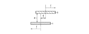
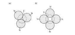
図26は、共鳴型非接触電力伝送における、複数の送電コイルの配置例を示したものである。図26(a)は、3個の送電コイル1a〜1cの配置例、図26(b)は4個の送電コイル1a〜1dの配置例を示す。この例では、各送電コイル1a〜1dは同一の寸法及び特性を有する。なお、送電コイル1a〜1dを総称する場合は、送電コイル1と記述する。
FIG. 26 shows an arrangement example of a plurality of power transmission coils in resonance-type non-contact power transmission. Fig.26 (a) shows the example of arrangement | positioning of the three
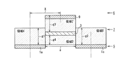
図27(a)及び(b)は、図26の送電コイル1a〜1c、及び送電コイル1a〜1dの配置に対して、電力の伝送を受ける受電コイル3が配置された状態を示す。図28に、図27(b)のA−A断面を示す。
27 (a) and 27 (b) show a state in which the
なお、磁界共鳴による電力伝送を行うためには、送電コイル1および受電コイル3はそれぞれ共振コイルを含んで構成され、送電側と受電側の共振コイル間の磁界共鳴を介して電力が伝送される。また、場合によっては共振コイルに対して給電し、あるいは共振コイルから給電を受けるために、例えば、各共振コイルに隣接させてループコイルが配置される。従って、送電コイル1および受電コイル3とは、共振コイルを含む送電側及び受電側のコイル構造を意味するものとする。
In order to perform power transmission by magnetic field resonance, the
各送電コイル1a〜1dは、同一平面上において互いに重ならないように形成する必要がある。即ち、送電コイル1の半径をrとすると、隣り合う二つの送電コイル1の中心間距離は、2r以上離れていることになる。そのため、図26(a)のように3個の送電コイルが配置された場合も、図26(b)のように4個の送電コイルが配置された場合も、送電コイル1a〜1c、あるいは送電コイル1a〜1dの配列の中心付近に、電力伝送効率が小さくなる死点領域2が生じる。従って、図27、図28に示すように、死点領域の中心に受電コイル3が配置された場合には、伝送効率の低下が問題となる可能性が高い。
The
電磁誘導型の非接触電力伝送装置においても同様の問題があり、特許文献1には、一次側の送電コイルから2次側の受電コイルへ非接触で電力を伝送する場合の、死点領域の存在による伝送効率の低下を抑制するための技術が開示されている。すなわち、送電コイルが複数用られ、かつそれぞれのコイルが重なり合うように配置される。例えば、送電コイルの直径をD、隣接する二つの送電コイルの中心間距離をXとした場合、D/2≦X≦D
となっている。これにより、伝送不能な死点領域を縮小、低減し、広い領域で安定した電力伝送が可能となる、とされている。
The electromagnetic induction type non-contact power transmission device has the same problem, and
It has become. Thereby, it is said that the dead center area | region which cannot be transmitted is reduced and reduced, and stable electric power transmission is attained in a wide area | region.
しかし、磁界共鳴型においては、隣接する二つの送電コイルを重ねることは伝送効率の低下を招くため、電磁誘導型と同様な対策としては用いることができない。すなわち、送電コイルを同一平面上に重ならないように配置した状態では、磁界共鳴型において伝送不能な死点領域が発生する可能性がある。 However, in the magnetic field resonance type, overlapping two adjacent power transmission coils causes a reduction in transmission efficiency, and thus cannot be used as a countermeasure similar to the electromagnetic induction type. That is, in a state where the power transmission coils are arranged so as not to overlap on the same plane, there is a possibility that a dead center region that cannot be transmitted in the magnetic field resonance type may occur.
また、携帯電話などの小型モバイル機器の充電用途では、送電コイルや受電コイルの大きさを小さくする必要があり、そのために伝送距離が短くなるという課題もあった。 Further, in charging applications for small mobile devices such as mobile phones, it is necessary to reduce the size of the power transmission coil and the power reception coil, which causes a problem that the transmission distance is shortened.
本発明は、このような従来技術における問題点を解決するものであり、死点の存在による伝送困難な領域を縮小し、または、送電コイルや受電コイルの大きさの制約による伝送距離の短縮化を回避して、磁界共鳴による電力伝送を広い領域に亘り安定して可能とする非接触電力伝送装置を提供することを目的とする。 The present invention solves such problems in the prior art, and reduces the transmission difficult region due to the existence of dead points, or shortens the transmission distance by limiting the size of the power transmission coil and power reception coil. It is an object of the present invention to provide a non-contact power transmission device that can stably perform power transmission over a wide area by avoiding the above-described problem.
本発明の非接触電力伝送装置は、共振コイルを含む受電コイルを備えた受電装置に対して電力を伝送するように構成され、共振コイルを含む送電コイルを備えて、前記受電コイル及び前記送電コイルの前記共振コイル間の磁界共鳴を介して電力を伝送するように構成される。 The non-contact power transmission device of the present invention is configured to transmit power to a power receiving device including a power receiving coil including a resonance coil, and includes a power transmission coil including the resonance coil, the power receiving coil and the power transmission coil The power is transmitted through magnetic field resonance between the resonance coils.
上記課題を解決するために、本発明の非接触電力伝送装置は、少なくとも1個の前記送電コイルが、同一平面上に互いに重ならないように配置された第1送電ユニットと、少なくとも1個の前記送電コイルが、同一平面上に互いに重ならないように配置された第2送電ユニットとを備える。前記第1送電ユニットと前記第2送電ユニットとは、相互の位置関係として少なくとも電力伝送配置を取ることが可能である。前記電力伝送配置では、前記第1及び第2送電ユニットは互いに対向し、相互間に前記受電装置を装着することが可能な受電空間を形成し、前記受電装置が前記受電空間に装着された配置では、前記送電コイル及び前記受電コイルにおける前記共振コイルの軸方向が互いに平行に配向される。 In order to solve the above-described problem, the contactless power transmission device of the present invention includes at least one power transmission coil disposed on the same plane so as not to overlap each other, and at least one of the power transmission coils. A power transmission coil is provided with the 2nd power transmission unit arrange | positioned so that it may not mutually overlap on the same plane. The first power transmission unit and the second power transmission unit can take at least a power transmission arrangement as a mutual positional relationship. In the power transmission arrangement, the first and second power transmission units face each other, form a power receiving space in which the power receiving device can be mounted, and the power receiving device is mounted in the power receiving space. Then, the axial directions of the resonance coil in the power transmission coil and the power reception coil are oriented parallel to each other.
本発明によれば、受電装置が配置される受電空間を挟んで上下に、第1送電ユニットと第2送電ユニットが配置されるので、受電装置の上下から電力伝送可能である。それにより、死点の存在による伝送困難な領域が縮小され、または、送電コイルや受電コイルの大きさの制約による伝送距離の短縮化が回避される。その結果、磁界共鳴による電力伝送が、広い領域に亘り安定して可能となり、受電装置の置き方の自由度が拡大する。 According to the present invention, since the first power transmission unit and the second power transmission unit are disposed above and below the power reception space in which the power reception device is disposed, power can be transmitted from above and below the power reception device. Thereby, the region where transmission is difficult due to the existence of the dead point is reduced, or shortening of the transmission distance due to the restriction of the size of the power transmission coil and the power reception coil is avoided. As a result, power transmission by magnetic field resonance can be stably performed over a wide area, and the degree of freedom in placing the power receiving apparatus is expanded.
本発明の非接触電力伝送装置は、上記構成を基本として、以下のような態様をとることができる。 The non-contact power transmission apparatus of the present invention can take the following aspects based on the above configuration.
すなわち、前記送電コイルによる電力伝送動作を制御する制御部を備え、前記制御部は、前記受電空間に前記受電装置が配置された状態で、前記第1及び第2送電ユニットのうち少なくとも一方に含まれる前記送電コイルから前記受電コイルに対して電力を伝送するように制御する構成とすることができる。 That is, a control unit that controls a power transmission operation by the power transmission coil is included, and the control unit is included in at least one of the first and second power transmission units in a state where the power reception device is disposed in the power reception space. It can be set as the structure which controls so that electric power may be transmitted with respect to the said receiving coil from the said power transmission coil.
また、前記送電コイルによる電力伝送動作を制御する制御部を備え、前記制御部は、前記第1送電ユニットまたは前記第2送電ユニットの一方に配置された任意の複数個の前記送電コイルから同時に電力を伝送させる制御機能を含む構成とすることができる。それにより、受電可能な領域を拡大することができる。 In addition, a control unit that controls a power transmission operation by the power transmission coil is provided, and the control unit simultaneously receives power from any of the plurality of power transmission coils arranged in one of the first power transmission unit or the second power transmission unit. It is possible to adopt a configuration including a control function for transmitting the data. Thereby, the area | region which can receive electric power can be expanded.
これらの構成においては、前記受電コイルの位置を検出するモニター部を備え、前記制御部は、検出された前記受電コイルの位置に応じて選択した前記送電コイルから電力を伝送するように制御する構成とすることができる。 In these configurations, a monitor unit that detects the position of the power receiving coil is provided, and the control unit performs control so that power is transmitted from the power transmission coil selected according to the detected position of the power receiving coil. It can be.
以上のように、受電ユニットの受電コイルへの電力伝送は、第1送電ユニットあるいは第2送電ユニットに配置されているいずれか1個もしくは同一平面上にある複数個の送電コイルの同時送電により行うように構成することが好ましい。これにより、電力伝送効率の向上や装置の簡素化が可能となり、送電装置のコストを低減することができる。 As described above, power transmission to the power receiving coil of the power receiving unit is performed by simultaneous power transmission of any one of the first power transmitting unit or the second power transmitting unit or a plurality of power transmitting coils on the same plane. It is preferable to configure as described above. As a result, it is possible to improve the power transmission efficiency and simplify the device, and to reduce the cost of the power transmission device.
より具体的には、例えば、第1送電ユニットと第2送電ユニットの距離のほぼ中間の位置に受電ユニットの受電コイルが位置する場合において、受電コイルの中心軸と、第1あるいは第2送電ユニットの送電コイルの中心軸とが近い位置にある場合には、一番中心軸に近い位置にある送電コイル1個のみで送電を行う。 More specifically, for example, when the power reception coil of the power reception unit is located at a position approximately in the middle of the distance between the first power transmission unit and the second power transmission unit, the central axis of the power reception coil and the first or second power transmission unit When the center axis of the power transmission coil is close to the center axis, power is transmitted by only one power transmission coil located closest to the center axis.
また、受電ユニットの受電コイルの中心軸が、第1あるいは第2送電ユニットの送電コイルの中心軸から送電コイルの半径の半分以上ずれている時は、同一平面上において受電コイルの中心軸に最も近い位置にある任意の2個の送電コイルによる同時送電を行う。このように、送電コイルを複数個同時に用いて送電を行うことにより、片面での電力伝送可能距離及び平面的範囲が拡大し、広い範囲で安定した電力伝送ができる。これにより、受電装置の置き方の自由度が拡大することになる。 Further, when the central axis of the power receiving coil of the power receiving unit is shifted from the central axis of the power transmitting coil of the first or second power transmitting unit by more than half of the radius of the power transmitting coil, the center axis of the power receiving coil is the most on the same plane. Simultaneous power transmission is performed by any two power transmission coils located close to each other. Thus, by performing power transmission using a plurality of power transmission coils at the same time, the power transmission distance and the planar range on one side are expanded, and stable power transmission can be performed over a wide range. Thereby, the freedom degree of how to place a power receiving apparatus expands.
また、前記第1及び前記第2送電ユニットには、それぞれ複数の前記送電コイルが含まれ、前記第1及び前記第2送電ユニットに含まれる少なくとも各々1個の送電コイルどうしは、互いの中心軸をずらして配置されている構成とすることができる。 Each of the first and second power transmission units includes a plurality of the power transmission coils, and at least one power transmission coil included in each of the first and second power transmission units has a central axis. It can be set as the structure arrange | positioned by shifting.
この場合、隣り合う任意の送電コイルの中心間距離は、両者の送電コイルの半径の総和以上とすることが好ましい。また、第1送電ユニットおよび第2送電ユニットの送電コイルの直径と、受電ユニットの受電コイルの直径がほぼ同じ方が、共振条件の関係から好ましい。更に、携帯電話等のモバイル機器に使用する時には、送受電装置の小型化が可能な平面状コイル(薄膜コイル)を用いることが好ましい。 In this case, it is preferable that the center-to-center distance between any adjacent power transmission coils be equal to or greater than the sum of the radii of both power transmission coils. Moreover, it is preferable from the relationship of resonance conditions that the diameters of the power transmission coils of the first power transmission unit and the second power transmission unit are substantially the same as the diameters of the power reception coils of the power reception unit. Furthermore, when used for mobile devices such as mobile phones, it is preferable to use a planar coil (thin film coil) that can reduce the size of the power transmitting and receiving device.
例えば、3個の送電コイルがそれぞれ接して配置されている送電ユニットにおいては、他方の送電ユニットの送電コイルの中心軸との最小ずれ量が、送電コイルの半径の(2√3/3)倍である。また、送電コイルがマトリックス状に配置されている送電ユニットにおいては、他方の送電ユニットの送電コイルの中心軸との最小ずれ量が、送電コイルの半径の√2倍である。また、送電コイルが最密充填状に形成されている送電ユニットにおいては、他方の送電ユニットの送電コイルの中心軸との最小ずれ量が送電コイルの半径とほぼ同じである。 For example, in a power transmission unit in which three power transmission coils are arranged in contact with each other, the minimum deviation amount of the other power transmission unit from the central axis of the power transmission coil is (2√3 / 3) times the radius of the power transmission coil. It is. Further, in the power transmission unit in which the power transmission coils are arranged in a matrix, the minimum deviation amount of the other power transmission unit from the central axis of the power transmission coil is √2 times the radius of the power transmission coil. Moreover, in the power transmission unit in which the power transmission coil is formed in the close-packed form, the minimum deviation amount from the central axis of the power transmission coil of the other power transmission unit is substantially the same as the radius of the power transmission coil.
あるいは、送電コイルが接しておらず、ある距離離れて配置されている場合には、例えば、第1送電ユニットにおける任意の2つの送電コイル間の距離のほぼ真ん中の位置に、第2送電ユニットの送電コイルの中心軸を位置させればよい。 Alternatively, when the power transmission coil is not in contact and is disposed at a certain distance, for example, the second power transmission unit is positioned at the middle of the distance between any two power transmission coils in the first power transmission unit. The central axis of the power transmission coil may be positioned.
また、前記第1及び前記第2送電ユニットに含まれる前記送電コイルの直径が同じであ
り、前記第1及び前記第2送電ユニットに各々含まれる前記送電コイル間の中心軸の最大ずれ量が、前記送電コイルの直径に等しい構成とすることができる。
Further, the diameters of the power transmission coils included in the first and second power transmission units are the same, and the maximum deviation amount of the central axis between the power transmission coils included in the first and second power transmission units, respectively, It can be set as the structure equal to the diameter of the said power transmission coil.
また、前記受電コイルは、前記共振コイルとともに、前記共振コイルに対して電磁誘導により電力を供給するループコイルを少なくとも2個備えている構成とすることができる。 The power receiving coil may be configured to include at least two loop coils that supply electric power to the resonant coil by electromagnetic induction together with the resonant coil.
この構成において、前記ループコイルは、前記共振コイルに対して中心軸方向における両側に配置されている構成とすることができる。また、前記複数の送電コイルのうちのいずれの送電コイルから送電されているかに応じて、動作させる前記ループコイルが切り替えられる構成とすることができる。 In this configuration, the loop coil may be arranged on both sides in the central axis direction with respect to the resonance coil. Further, the loop coil to be operated can be switched depending on which power transmission coil of the plurality of power transmission coils is transmitting power.
このように、受電装置を、上下どちらからでも充電可能な構造とすることが好ましい。例えば、送電コイルと受電コイルの間に金属等があると、十分な磁界共鳴の作用が得られないので、受電コイルが位置する両側の領域には金属が無い構造とする。ループコイルを切り替えるパラメータとしては、受電する電力量や電力伝送を行う送電コイルと受電コイルとの位置関係などを用いることができる。 Thus, it is preferable that the power receiving device has a structure that can be charged from above and below. For example, if there is a metal or the like between the power transmission coil and the power reception coil, a sufficient magnetic field resonance effect cannot be obtained. As a parameter for switching the loop coil, the amount of electric power to be received, the positional relationship between the power transmission coil and the power reception coil that perform power transmission, and the like can be used.
また、前記受電コイルの位置を検出するモニター部と、検出された前記受電コイルの位置に応じて、前記第1送電ユニット及び前記第2送電ユニットの前記送電コイルの位置を、電力伝送効率が最大となるように制御する送電コイル位置制御部とを備えている構成とすることができる。それにより、伝送効率の低下を抑制することができる。 In addition, the monitor unit that detects the position of the power receiving coil, and the position of the power transmitting coil of the first power transmission unit and the second power transmission unit according to the detected position of the power receiving coil, the power transmission efficiency is maximum. It can be set as the structure provided with the power transmission coil position control part controlled to become. Thereby, a decrease in transmission efficiency can be suppressed.
また、前記第1送電ユニットに含まれる前記送電コイルの数と、前記第2送電ユニットに含まれる前記送電コイルの数が異なる構成とすることができる。送電装置のコストを考えると、どちらかの送電ユニットに含まれる送電コイルの総数を少なくすることが好ましい。受電ユニットの受電コイルを1個とすることにより、受電装置のコストを低減することができる。 The number of the power transmission coils included in the first power transmission unit may be different from the number of the power transmission coils included in the second power transmission unit. Considering the cost of the power transmission device, it is preferable to reduce the total number of power transmission coils included in either power transmission unit. By using one power receiving coil of the power receiving unit, the cost of the power receiving device can be reduced.
また、前記第1送電ユニット及び前記第2送電ユニットを保持し、前記受電装置を着脱可能に装着することが可能であり、かつ、前記第1及び第2送電ユニットが前記電力伝送配置にあるときに、前記受電空間に前記受電装置が配置されるように構成された筐体を備え、前記電力伝送配置では、前記送電コイルと前記受電コイルの周囲が前記筐体内で電磁シールドされる構成とすることができる。 When the first power transmission unit and the second power transmission unit are held, the power receiving device can be detachably mounted, and the first and second power transmission units are in the power transmission arrangement. The power receiving device includes a housing configured to arrange the power receiving device in the power receiving space, and the power transmission arrangement is configured to electromagnetically shield the periphery of the power transmission coil and the power receiving coil within the housing. be able to.
この構成において、携帯電話に使用される周波数帯域の電波を前記筐体内へ送るための中継コネクタが設けられている構成とすることができる。 In this configuration, a relay connector for sending radio waves in a frequency band used for a mobile phone into the housing can be provided.
磁界共鳴により電力を伝送する場合、実際に実用化された時には周波数としては数MHz〜数100MHz帯を活用することが考えられる。電界共鳴型に比べて人体への影響が少ないとはいえ、送電パワーの値によっては人体への影響も考慮しなければならない。そこで、上記構成のように、電力伝送を行っている時には送電コイル及び受電コイルを、外部に電磁波が漏れないようにシールドをした筐体で全体を包囲することが好ましい。これにより、送電コイルから発生したエネルギーのうち受電されずに放射されたエネルギーが外部に漏れる心配がなくなる。 When power is transmitted by magnetic field resonance, it is conceivable to use a frequency band of several MHz to several hundred MHz when actually put into practical use. Although the influence on the human body is less than that of the electric field resonance type, the influence on the human body must be taken into account depending on the value of the transmission power. Therefore, as in the above-described configuration, it is preferable that the power transmission coil and the power reception coil are entirely surrounded by a casing that is shielded so that electromagnetic waves do not leak to the outside during power transmission. Thereby, there is no fear that the energy radiated without being received out of the energy generated from the power transmission coil leaks to the outside.
但し、携帯電話の電力伝送の場合には、通常の携帯電話用の電波がシールドによって電子メールなどのやり取りができない状態を回避するために、電力伝送に使用する特定の周波数のみ外部への遮断を行うことが好ましい。あるいは、シールドをした筐体の任意の部分に、携帯電話用の電波を筐体の内部と外部でやり取りする中継装置を設けても良い。ま
た、受電装置と筐体との間で情報のやり取りをするシステムを取り付け、受電装置の受電が完了すると筐体の任意の場所でその旨がわかる表示(あるいは音など)をするようにしてもよい。筐体の形としては、蓋が開閉できるようなオルゴール型や、机の引き出し型等が好ましい。そして、安全確保のために、蓋が開いている時や引き出しが閉まっていない時には電力伝送が不能となるようにすることが好ましい。
However, in the case of mobile phone power transmission, in order to avoid the situation where normal mobile phone radio waves cannot exchange e-mail etc. due to the shield, only the specific frequency used for power transmission is blocked to the outside. Preferably it is done. Alternatively, a relay device that exchanges radio waves for mobile phones between the inside and the outside of the casing may be provided in an arbitrary portion of the shielded casing. In addition, a system for exchanging information between the power receiving device and the housing may be installed so that a display (or sound) indicating that the power receiving device is in an arbitrary location when power reception of the power receiving device is completed. Good. As the shape of the housing, a music box type that can be opened and closed, a desk drawer type, and the like are preferable. In order to ensure safety, it is preferable that power transmission be disabled when the lid is open or when the drawer is not closed.
また、前記筐体が前記電力伝送配置の状態を維持するためのインターロック機能を備え、電力伝送時には、前記送電コイルと前記受電コイルの周囲が電磁シールドされた状態が前記インターロック機能により維持される構成とすることができる。 In addition, the housing has an interlock function for maintaining the state of the power transmission arrangement, and during power transmission, a state where the power transmission coil and the power receiving coil are electromagnetically shielded is maintained by the interlock function. It can be set as a structure.
また、前記送電コイルに含まれた前記共振コイルの磁気抵抗値を各々検出する磁気抵抗値検出部を備え、前記制御部は、検出された磁気抵抗値が最小となる前記送電コイルを選択し、選択された前記送電コイルから電力を伝送するか、または、選択された前記送電コイルを含む隣接した複数の前記送電コイルから同時に電力を伝送するように制御する構成とすることができる。 In addition, the magnetic resistance value detection unit for detecting the magnetic resistance value of the resonance coil included in the power transmission coil, respectively, the control unit selects the power transmission coil with the minimum detected magnetic resistance value, It can be set as the structure which transmits so that electric power may be transmitted from the selected said power transmission coil, or may be transmitted simultaneously from the several said adjacent power transmission coil containing the selected said power transmission coil.
また、前記受電コイルの受電電力を検出する電力検出部を備え、前記制御部は、複数の前記送電コイルから個別に順次電力を伝送させて、前記電力検出部が出力する検出値が最大となる前記送電コイルを選択し、選択された前記送電コイルから電力を伝送するか、または、選択された前記送電コイルを含む隣接した複数の前記送電コイルから同時に電力を伝送するように制御する構成とすることができる。 In addition, a power detection unit that detects the received power of the power reception coil is provided, and the control unit sequentially transmits power individually from the plurality of power transmission coils, and the detection value output by the power detection unit is maximized. The power transmission coil is selected, and power is transmitted from the selected power transmission coil, or power is transmitted from a plurality of adjacent power transmission coils including the selected power transmission coil at the same time. be able to.
また、受電側に共鳴用の受電コイル以外に、位置モニター用のコイルを設けてもよい。この場合には、第1送電ユニットあるいは第2送電ユニットのどちらかの送電側に、共鳴用の送電コイル以外に位置モニター用のコイルを設ける必要がある。 In addition to the resonance power receiving coil, a position monitoring coil may be provided on the power receiving side. In this case, it is necessary to provide a position monitoring coil in addition to the resonance power transmission coil on the power transmission side of either the first power transmission unit or the second power transmission unit.
以下、本発明の実施の形態について、図面を参照しながら説明する。 Hereinafter, embodiments of the present invention will be described with reference to the drawings.
<実施の形態1>
図1は、実施の形態1における磁界共鳴型の非接触電力伝送装置の構成を示す断面図、図2はその平面図である。図1は、図2のB−B線に沿った断面を示す。なお、図26〜図28に示した従来例の非接触電力伝送装置と同様の要素については、同一の参照番号を付して、説明を簡略化する。
<
FIG. 1 is a cross-sectional view showing a configuration of a magnetic field resonance type non-contact power transmission apparatus according to
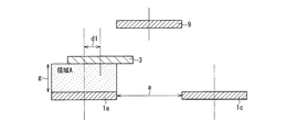
本実施の形態の非接触電力伝送装置(送電装置)4は、下側に配置される第1送電ユニット5と、上側に配置される第2送電ユニット6とを備えている。図1のように互いに対向するように配置された場合の第1送電ユニット5と第2送電ユニット6の相互間には、所定間隔の受電空間が形成されている。この受電空間に受電装置7を装着して電力の伝送を行うように構成されている。第1送電ユニット5は、基板8の同一平面上に互いに重ならないように配置された4個の送電コイル1a〜1dにより構成されている。第2送電ユニット6は、1個の送電コイル9により構成されている(基板の図示は省略)。
The non-contact power transmission device (power transmission device) 4 of the present embodiment includes a first
送電コイル1a〜1d及び送電コイル9は、各々磁界共鳴を作用させるための共振コイル(図示省略)を含んで構成される。送電コイル1a〜1dは、共振コイルの軸方向が互いに平行に配向するように基板8上に配置されている。なお、以下の図面では、基板8の図示は省略する。また、第1及び第2送電ユニット5、6は、各々における共振コイルの軸方向が相互に平行に配向するように配置されている。
Each of the power transmission coils 1a to 1d and the
図1に示した第1及び第2送電ユニット5、6の配置は、電力伝送時の配置(電力伝送配置)である。受電装置7は、共振コイルを有する受電コイル3を1個備えて構成されて
いる。電力伝送配置では、第1及び第2送電ユニット5、6の共振コイルと、受電コイル3の共振コイルとの間の磁界共鳴を介して電力を伝送することが可能である。受電装置7も基板を用いて構成されるが、基板の図示は省略する。なお、第1及び第2送電ユニット5、6は、電力伝送配置に固定されても良いし、後述するように、受電空間が形成されていない他の状態を取ることも可能なように構成されてもよい。
The arrangement of the first and second
また、後述するように、第2送電ユニット6が複数の送電コイル9を備えた構成とすることもできる。その場合の第2送電ユニット6の複数の送電コイル9も、同一平面上に互いに重ならないように、かつ共振コイルの軸方向を互いに平行に配向させて配置される。
Moreover, the 2nd
本実施の形態のように、第1及び第2送電ユニット5、6が上下に配置された電力伝送配置を採用することにより、以下に説明するように、広範囲の領域において最適な送受電が可能となる。
By adopting a power transmission arrangement in which the first and second
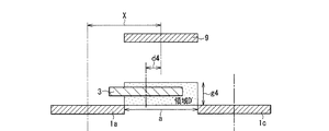
先ず、送電コイルと受電コイルとの中心軸のずれ量に応じた、電力伝送効率の変化について調べた実験の結果について述べる。ここで、図3に示すように、送電コイル1の半径r1及び受電コイル3の半径r2を、r1=r2=rとし(送電コイル1の半径と受電コイル3の半径を同じにした方が、共鳴条件を合わせやすい)、送電コイル1と受電コイル3の距離(軸方向における間隔)をg、送電コイル1の中心軸と受電コイル3の中心軸のずれ量をdとする。実験では、r=150mm、g=150mmで固定とし、中心軸の位置ずれ量dを可変とした。また、両コイルの共振コイルとしてはヘリカルアンテナを使用し、巻数を5ターンとした(ピッチは5mm)。
First, the result of the experiment which investigated the change of electric power transmission efficiency according to the deviation | shift amount of the central axis of a power transmission coil and a receiving coil is described. Here, as shown in FIG. 3, the radius r1 of the
図4に、上記実験の結果得られた、中心軸の位置ずれ量dに対する電力伝送効率ηの関係を示す。位置ずれ量dが150mm程度までは電力伝送効率ηは約95%と変化が無く、それよりも位置ずれ量dが大きくなると電力伝送効率ηが低下していくことが判る。 FIG. 4 shows the relationship between the power transmission efficiency η and the positional deviation amount d of the central axis, obtained as a result of the above experiment. It can be seen that the power transmission efficiency η does not change to about 95% until the positional deviation amount d is about 150 mm, and the power transmission efficiency η decreases as the positional deviation amount d becomes larger than that.
この結果から、送電コイル1及び受電コイル3の中心軸の位置ずれが、コイルの半径rまでの範囲においては、問題なく最大の電力伝送が可能であることが判る。このような関係は、送電コイル1及び受電コイル3の半径rを変えた場合においてもほぼ同様である。また、ヘリカルアンテナに限らず平面型コイル(薄膜コイルなど)を用いた場合でも、傾向はほぼ同じである。
From this result, it can be seen that maximum power transmission is possible without any problem in the range where the displacement of the central axis of the
これに対して、電磁誘導型の場合は、送電コイル1及び受電コイル3の中心軸がコイルの半分ずれると電力伝送効率がほぼ0に近づくので、電磁誘導型に比べて、磁界共鳴型は位置ずれに対して優れていることが判る。
On the other hand, in the case of the electromagnetic induction type, the power transmission efficiency approaches almost 0 when the central axes of the
ここで、位置ずれによる電力伝送効率の低下の原因としては、送電コイル1と受電コイル3の中心間距離が大きくなると、結合自体が弱くなるために電力伝送が低下しているものと考えられる。以上の説明では、送電コイル1の半径と受電コイル3の半径を同じにした場合について述べたが、半径が異なっていても、同様の結果が得られた。その場合には、共鳴条件を合わせる必要がある。また、位置ずれ量dの範囲を決める半径rは、送電コイル1の半径r1である。
Here, it is considered that the cause of the decrease in the power transmission efficiency due to the displacement is that when the distance between the centers of the
ここで例えば図27(b)のように送電コイル1が4個の送電ユニットにおいて、死点領域の中心に受電コイル3がある場合には、送電コイル1と受電コイル3の中心軸のずれ量dは、√2rとなる。従って、図4の関係から電力伝送効率が悪くなる可能性が高い。これについて判り易くするために、図27(b)のA−A断面図に送電コイル1による作用を加えたものを図5に示す。図5は、送電コイル1の中心軸と受電コイル3の中心軸のずれ量dがコイルの半径rよりも大きい場合を示す。送電コイル1aと送電コイル1cと
は、距離aだけ離れている。送電コイル1aの中心軸と受電コイル3の中心軸のずれ量をd1と記し、送電コイル1cの中心軸と受電コイル3の中心軸のずれ量をd2と記す。
Here, for example, as shown in FIG. 27 (b), in a power transmission unit with four power transmission coils 1, when the
領域A、及び領域Bは、最大効率の電力伝送が可能な領域を模式的に示したものである。領域Aは、中心軸のずれ量d1が半径r以内の場合に、最大の電力伝送効率が得られる領域である。但し、最大の電力伝送効率とは、実用的に十分な範囲内の値として定義される電力伝送効率を意味する。領域Bは、中心軸のずれ量d2が半径r以内の場合に最大の電力伝送効率が得られる領域である。受電コイル3の中心軸が送電コイル1aと送電コイル1cの間の距離aの領域にある場合には、電力伝送効率が低くなることがわかる。送電コイル1aと送電コイル1cの中心間距離の半分の位置に受電コイル3の中心軸が位置する時(d1=d2)に、電力伝送効率が最も悪くなると考えられる。
Region A and region B schematically show regions where maximum efficiency power transmission is possible. Region A is a region where the maximum power transmission efficiency can be obtained when the deviation d1 of the central axis is within radius r. However, the maximum power transmission efficiency means power transmission efficiency defined as a value within a practically sufficient range. The region B is a region where the maximum power transmission efficiency can be obtained when the deviation d2 of the central axis is within the radius r. It can be seen that when the central axis of the
そこで、本実施の形態では、死点の影響による電力伝送効率低下を防ぐために、図1に示したように、受電コイル3を挟んだ送電コイル1aの反対側に、第2送電ユニット6に含まれる半径rのもう一つの送電コイル9を配置する。それらの位置関係を、図6に示す。送電コイル9の中心軸と受電コイル3の中心軸のずれ量をd3と記す(図6ではd3=0のため図示せず)。図6に示すように、送電コイル9と受電コイル3の伝送方向距離は、例えば、送電コイル1aと受電コイル3の間の距離gと同じにする。送電コイル9により、中心軸のずれ量d3が半径r以内の場合における最大の電力伝送効率が得られる領域Cが追加される。
Therefore, in the present embodiment, in order to prevent a decrease in power transmission efficiency due to the influence of the dead point, the second
この構成では、送電コイル1aと送電コイル1cとの中心間距離の半分の位置に送電コイル9の中心軸が来た時が、一番多くの領域をカバーできる。即ち、送電コイル1aと送電コイル9との中心軸の好ましいずれ量Xは、X=(2r+a)/2である。(2r+a)は送電コイル1aと送電コイル9の中心軸間の距離である。ここで、平面方向における最大の受電可能領域を与える最大ずれ量Xmaxは、a=2r(送電コイル9の直径)の場合に対応する。従って、Xmax=2rとなる。そして、受電コイル3が配置されている位置での平面方向の最適な受電が可能な範囲Zは、(4r+a)で表される。最大の受電可能範囲Zmaxはa=2rの時であるので、Zmax=6rとなる。
In this configuration, the most area can be covered when the central axis of the
図6に示すように送電コイル1a〜1d、9を配置することにより、広範囲の領域において最適な送受電が可能となる。しかし、実際にすべての送電コイルから一つの受電コイルに同時送電を行うことは、効率の問題から好ましくない場合がある。そこで、受電コイル3の中心軸がどの領域にあるかに応じて、実際に送電を実施する送電コイルを1個選択することが望ましい。これについて、図7〜図9を参照して説明する。なお、判り易くするために、平面方向における最大の受電可能領域を与える最大ずれ量Xmaxが2r(a=2r)の場合について示す。
By arranging the power transmission coils 1a to 1d and 9 as shown in FIG. 6, optimal power transmission / reception is possible in a wide area. However, it may not be preferable to actually perform simultaneous power transmission from all the power transmission coils to one power reception coil due to efficiency problems. Therefore, it is desirable to select one power transmission coil that actually performs power transmission, depending on which region the central axis of the
図7〜図9は、受電コイル3の水平方向位置が、領域A〜領域Cの各領域に対応する場合に分けて伝送方法を示したものである。図7は、送電コイル1aの中心軸からの受電コイル3の中心軸のずれ量d1が、半径r以内である場合を示している。この場合には、領域Aで最大の電力伝送効率が得られるので、送電コイル1aのみによって受電コイル3へ送電を行えばよい。
FIG. 7 to FIG. 9 show the transmission method separately when the horizontal position of the
同様に、図8に示すように、送電コイル9の中心軸からの受電コイル3の中心軸のずれ量d3が半径r以内の時には、領域Cで最大の電力伝送効率が得られるので、送電コイル9のみによって受電コイル3へ送電を行えばよい。更に、図9に示すように、送電コイル1cの中心軸からの受電コイル3の中心軸のずれ量d2が半径r以内の時には、領域Bで最大の電力伝送効率が得られるので、送電コイル1cのみによって受電コイル3へ送電を行えばよい。
Similarly, as shown in FIG. 8, when the amount of deviation d3 of the central axis of the
このように、送電コイル1a〜1d、9から選択された1つの送電コイルにより電力伝送を行うために、各送電コイル1a〜1d、9から選択するための制御部を設け、例えば、受電コイル3の位置を検出するモニター部を設ける(図示省略)。そして、制御部は、検出された受電コイル3の位置に応じて選択した送電コイルから電力を伝送するように制御する。モニター部としては、例えば、受電装置7に対してレーザ光を照射し、反射光に基づいて受電装置7の位置や、姿勢を検出する構成とすることができる。受電装置7内における受電コイル3の位置は特定されているので、受電コイル3の位置を検出することが可能である。あるいは、撮像装置により受電装置7を撮影し、パターン認識により受電装置7の位置を検出することも可能である。
Thus, in order to perform power transmission with one power transmission coil selected from the power transmission coils 1a to 1d and 9, a control unit for selecting from each
以上のように、本実施の形態では、死点となりうる領域の中心付近に受電コイル3が位置した場合を考慮し、従来の送電コイル1a及び送電コイル1cを有する第1送電ユニット5に加えて、送電コイル9を有する第2送電ユニット6をほぼ平行に対向させ、第1送電ユニット5の送電コイル1の中心軸と第2送電ユニット6の送電コイル9の中心軸を適度にずらした状態に配置する。第1送電ユニット5と第2送電ユニット6の間に、受電コイル3を有する受電ユニット9を装着し、少なくともどちらか一方の送電コイルから受電コイル3に非接触で電力を伝送する。
As described above, in the present embodiment, in consideration of the case where the
図10は、平面構造が図2の場合と異なり、第1送電ユニット5に、3個の送電コイル1a〜1cがそれぞれ接して配置された場合に、第2送電ユニット6に設けた送電コイル9の最適な配置例を示す。即ち、死点となりうる領域の中心付近に送電コイル9の中心軸を位置させるのが好ましい。この場合には、第1送電ユニット側の送電コイル1aと第2送電ユニット側の送電コイル9との中心軸のずれ量は、コイルの半径をrとすると、(2√3/3)rである。
FIG. 10 differs from the case of FIG. 2 in the planar structure, and when the three power transmission coils 1a to 1c are arranged in contact with the first
<実施の形態2>
図11Aは、実施の形態2における磁界共鳴型の非接触電力伝送装置の構成を示す断面図、図11Bはその平面図である。図11Aは、図11BのC−C線に沿った断面を示す。
<
FIG. 11A is a cross-sectional view illustrating a configuration of a magnetic field resonance type non-contact power transmission apparatus according to
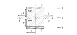
本実施の形態は、送電方向(送電コイルの軸方向)おける受電可能領域の拡大を目的とした送電コイルの配置例に関するものである。図11A、図11Bの配置は、第1送電ユニット5及び第2送電ユニット6がそれぞれ1個の送電コイル1、9を有し、送電コイル1と送電コイル9の中心軸がほぼ一致している例である。第1送電ユニット5と第2送電ユニット6とは、相互間に所定間隔の受電空間を形成して互いに対向し、各々における共振コイルの軸方向が相互に平行に配向するように配置されている。相互間の受電空間には、受電装置7の受電コイル3が配置される。図中、実線で描かれた受電コイル3の位置は、その中心軸が送電コイル1、9の中心軸から左側に距離rずれている場合を示す。一方、破線で描かれた受電コイル(3)の位置は、その中心軸が送電コイル1、9の中心軸から右側に距離rずれている場合を示す。
The present embodiment relates to an example of arrangement of power transmission coils for the purpose of expanding a power receiving area in the power transmission direction (axial direction of the power transmission coil). 11A and 11B, the first
図11Aに示す配置の場合には、領域Aと領域Cとを併せた領域で、良好な電力伝送が可能である。すなわち、送電コイル1からは、送電コイル1の中心軸と受電コイル3の中心軸のずれ量が半径r以内の領域Aで最大の電力伝送効率が得られる。送電コイル9からは、送電コイル9の中心軸と受電コイル3の中心軸のずれ量が半径r以内の場合の領域Cで最大の電力伝送効率が得られる。
In the case of the arrangement shown in FIG. 11A, good power transmission is possible in the region where region A and region C are combined. That is, from the
即ち、従来の送電コイル1が1個の場合は、最大の電力伝送効率は領域Aでのみ得られるのに比べて、送電方向に最大で2倍の受電可能領域が得られることになる。この時の、
平面上の最適な受電可能範囲Zmaxは、受電コイル3の位置と受電コイル(3)の位置の各々の中心軸間の距離で、従来と同じZm=2rである。
That is, when the conventional
The optimum power receiving range Zmax on the plane is the distance between the central axes of the position of the
本実施の形態のように、第1送電ユニットに形成された任意の送電コイルの伝送効率最大の距離と、第2送電ユニットに形成された任意の送電コイルの伝送効率最大の距離を合計した距離だけ両送電コイル間を離し、且つ両送電コイルの中心軸をほぼ一致させて対向配置することにより、結果的に送電方向おける受電可能領域の拡大が可能となる。 As in the present embodiment, the distance obtained by adding the maximum transmission efficiency distance of any power transmission coil formed in the first power transmission unit and the maximum transmission efficiency distance of any power transmission coil formed in the second power transmission unit As a result, it is possible to enlarge the power receiving area in the power transmission direction by separating the power transmission coils from each other and arranging the power transmission coils so that the central axes of the power transmission coils are substantially coincident with each other.
<実施の形態3>
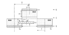
実施の形態3における磁界共鳴型の非接触電力伝送装置について、図12を参照して説明する。本実施の形態では、送電コイルの配置は、実施の形態1の図6に示した送電コイル1a〜1d、及び送電コイル9と同じ配置である。但し図12には、受電コイル3が受電可能領域から外れた位置に配置された状態が示される。この場合、受電コイル3の中心軸のずれ量d3が半径r以内であるにもかかわらず、最大の電力伝送効率が得られる領域Cから伝送方向に遠く離れてしまっているために、伝送効率が低下する。
<
A magnetic resonance type non-contact power transmission apparatus according to
そこで、本実施の形態では、受電コイル3の位置をモニターし、平面上における受電コイル3の中心位置に、送電コイル1aと送電コイル1cの平面上の位置と送電コイル9の平面上の位置の中間位置(距離g)が来るように、送電コイル1aと送電コイル1c及び送電コイル9の位置を移動させる。
Therefore, in the present embodiment, the position of the
場合によっては、図13に示すように、送電コイル9のみを、受電コイル3における最大の電力伝送効率となるように、伝送方向に距離tだけ移動させても良い。このように、受電コイルの位置に応じて送電コイルの位置を適度に移動させることにより、確実な電力伝送が可能となる。
In some cases, as shown in FIG. 13, only the
<実施の形態4>
実施の形態4における磁界共鳴型の非接触電力伝送装置について、図14〜図20を参照して説明する。本実施の形態は、受電コイルが最大の電力伝送効率の領域から外れた場合の解決策として、実施の形態3の場合の送電コイルの位置を移動させる方法とは異なる方法を提供するものである。すなわち、上述の各実施の形態においては、受電コイルへの電力伝送は基本的に1個の送電コイルで行うのに対して、本実施の形態では、同一平面上に配置された任意の2個の送電コイルから同時に送電する制御を含む。
<Embodiment 4>
A magnetic resonance type non-contact power transmission apparatus according to the fourth embodiment will be described with reference to FIGS. The present embodiment provides a method different from the method of moving the position of the power transmission coil in the case of the third embodiment as a solution when the power reception coil deviates from the region of maximum power transmission efficiency. . That is, in each of the above-described embodiments, power transmission to the power receiving coil is basically performed by one power transmission coil, whereas in the present embodiment, any two pieces arranged on the same plane. Including control for simultaneously transmitting power from the power transmission coil.
まず、本実施の形態の構成に関し、送電コイルと受電コイルとの中心軸のずれ量に応じた電力伝送効率の変化について調べた実験の結果について説明する。実験は、図14に示すように、2個の送電コイル1a、1c間の距離aを、最も電力伝送効率が小さくなると思われる2r(受電コイル3の直径)で固定とし、両送電コイル1a、1cから同時に送電したときの、送電コイル1a及び受電コイル3の中心軸のずれ量dに対する電力伝送効率の変化を測定した。
First, regarding the configuration of the present embodiment, the results of an experiment examining changes in power transmission efficiency according to the amount of deviation of the central axis between the power transmission coil and the power reception coil will be described. In the experiment, as shown in FIG. 14, the distance a between the two power transmission coils 1a and 1c is fixed at 2r (the diameter of the power reception coil 3), which seems to have the smallest power transmission efficiency, and both
ここで、送電コイル1a、送電コイル1c、及び受電コイル3の半径を共にr、送電コイル1aと受電コイル3の送信方向における距離をg、送電コイル1aの中心軸と受電コイル3の中心軸とのずれ量をdとする。実験では、r=150mm、g=150mm、a=300mmで固定とし、中心軸の位置ずれ量dを可変とした。実験結果として、中心軸の位置ずれ量dに対する電力伝送効率ηの関係を、図15に示す。位置ずれ量dが150mm(=r)程度までは電力伝送効率ηは約95%と変化が無く、それよりも位置ずれ量dが大きくなると電力伝送効率ηが低下していくことが判る。
Here, the radius of the
この結果から、送電コイル1と受電コイル3の中心軸の位置ずれ量dがコイルの半径r
までの範囲では、問題なく最大の電力伝送効率を得ることが可能であることが判る。更に、中心軸の位置ずれ量dが半径の2倍、即ち受電コイル3の直径分(2r=300mm)離れても、電力伝送効率の低下は2割程度と小さいことが判った。このような関係は、送電コイル及び受電コイルの半径を変えた場合においてもほぼ同様である。これによれば、電力伝送効率を80%程度と小さくしても送電パワーに余裕がある場合においては、送電方向おける受電可能領域の拡大が可能となる。
From this result, the positional deviation amount d between the central axes of the
It can be seen that the maximum power transmission efficiency can be obtained without any problem within the above range. Further, it has been found that even when the positional deviation amount d of the central axis is twice the radius, that is, away from the diameter of the power receiving coil 3 (2r = 300 mm), the decrease in power transmission efficiency is as small as about 20%. Such a relationship is substantially the same when the radii of the power transmission coil and the power reception coil are changed. According to this, even if the power transmission efficiency is reduced to about 80%, when there is a margin in the power transmission power, it is possible to expand the power reception possible area in the power transmission direction.
図16は、電力伝送効率が80%程度である領域を示したものである。送電コイル1aの中心軸と受電コイル3の中心軸のずれ量が半径r以内の時に、送電コイル1aにより80%の電力伝送効率が得られる領域A’における送電方向の電力伝送距離g1は、図6における送電方向の電力伝送距離gよりも大きい。同様に、送電コイル1cの中心軸と受電コイル3の中心軸のずれ量が半径r以内の時に、送電コイル1cにより80%の電力伝送効率が得られる領域B’における送電方向の電力伝送距離g2は、図6における送電方向の電力伝送距離gよりも大きい。また、送電コイル9の中心軸と受電コイル3の中心軸のずれ量が半径r以内の時に、受電コイル3により80%の電力伝送効率が得られる領域C’における送電方向の電力伝送距離g3は、図6における送電方向の電力伝送距離gよりも大きい。即ち、g1=g2=g3>gとなる。
FIG. 16 shows a region where the power transmission efficiency is about 80%. When the amount of deviation between the central axis of the
以上の領域A’、領域B’、領域C’は、1個の送電コイルにより電力伝送を行った場合に80%の電力伝送効率が得られる範囲であるが、図16における領域D’は、送電コイル1aと送電コイル1cにより同時に送電を行った場合に80%の電力伝送効率が得られる範囲である。結果的に、送電コイル9における領域C’と領域D’を加えた領域における送電方向の最大伝送距離は、(g3+g4)と、従来に比べて大きくすることができる。
Region A ′, region B ′, and region C ′ described above are ranges in which 80% power transmission efficiency is obtained when power transmission is performed with one power transmission coil, but region D ′ in FIG. The power transmission efficiency is 80% when power is transmitted simultaneously by the
図17〜図19は、平面方向において最大受電可能領域を形成する最大ずれ量Xmが2r(a=2r)の場合の、各領域における伝送方法を示したものである。図17は、受電コイル3の中心軸が送電コイル1aの中心軸から半径r以内の距離にある場合を示している。すなわち、送電コイル1aの中心軸と受電コイル3の中心軸のずれ量d1が半径r以内である。また、受電コイル3と送電コイル1aの間隔がg1以内である。すなわち、受電コイル3は、送電コイル1aによって最大の電力伝送効率が得られる領域A’に位置しているので、送電コイル1aのみによって受電コイル3へ送電を行えばよい。
17 to 19 show a transmission method in each region when the maximum shift amount Xm forming the maximum power receiving region in the planar direction is 2r (a = 2r). FIG. 17 shows a case where the central axis of the
同様に、図18は、送電コイル9の中心軸と受電コイル3の中心軸のずれ量d3が半径r以内であって、受電コイル3と送電コイル9の送電方向の間隔がg3以内の場合を示す。この場合は、受電コイル3は、送電コイル9によって最大の電力伝送効率が得られる領域C’に位置しているので、送電コイル9のみによって受電コイル3へ送電を行えばよい。
Similarly, FIG. 18 shows a case where the shift amount d3 between the central axis of the
更に、図19は、送電コイル9の中心軸と受電コイル3の中心軸のずれ量d4が半径r以内であって、受電コイル3と送電コイル1aの送電方向の間隔がg4以内の場合を示す。この場合は、受電コイル3は、送電コイル1aと送電コイル1cによって最大の電力伝送効率が得られる領域D’に位置しているので、送電コイル1aと送電コイル1cとの同時送電により受電コイル3へ送電を行えばよい。
Further, FIG. 19 shows a case where the deviation d4 between the central axis of the
また、図20は、送電コイル1cの中心軸と受電コイル3の中心軸のずれ量d2が半径r以内であって、受電コイル3と送電コイル1cの送電方向の間隔がg2以内の場合を示す。この場合は、受電コイル3は、送電コイル1cによって最大の電力伝送効率が得られる領域B’に位置しているので、送電コイル1cのみによって受電コイル3へ送電を行えばよい。
FIG. 20 shows a case where the shift amount d2 between the central axis of the
以上のとおり、本実施の形態では、最適な電力伝送可能な範囲を広げるために、実施の形態1と同様、従来のように送電コイルが設けられた第1送電ユニットに、追加の送電コイルが設けられた第2送電ユニットをほぼ平行に対向させ、第1送電ユニットの送電コイルの中心軸と第2送電ユニットの送電コイルの中心軸を適度にずらした状態に設定する。そして、第1送電ユニットと第2送電ユニットの間の受電空間に受電ユニットを配置し、受電コイルの位置に応じて、少なくとも一方の送電コイルを1個、あるいは2個の送電コイルを同時に動作させて、電力を伝送する。なお、送電コイルの配置によっては、同一平面上に形成した3個以上の送電コイルによる同時送電を行っても良い。 As described above, in this embodiment, in order to expand the range in which the optimum power can be transmitted, an additional power transmission coil is added to the first power transmission unit in which the power transmission coil is provided as in the conventional case, as in the first embodiment. The provided 2nd power transmission unit is made to oppose substantially parallel, and the center axis | shaft of the power transmission coil of a 1st power transmission unit and the center axis | shaft of the power transmission coil of a 2nd power transmission unit are set to the state shifted moderately. Then, the power receiving unit is disposed in the power receiving space between the first power transmitting unit and the second power transmitting unit, and at least one power transmitting coil or two power transmitting coils are operated simultaneously according to the position of the power receiving coil. And transmit power. In addition, depending on arrangement | positioning of a power transmission coil, you may perform simultaneous power transmission by the 3 or more power transmission coils formed on the same plane.
<実施の形態5>
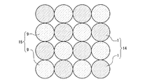
図21は、実施の形態5における磁界共鳴型の非接触電力伝送装置の構成を示す平面図である。本実施の形態では、第1送電ユニット10に設けられた送電コイル1は、4×4個がマトリックス状に配置され、第2送電ユニット11に設けられた複数個の送電コイル9が対向させて配置された構成を有する。
<
FIG. 21 is a plan view showing the configuration of the magnetic field resonance type non-contact power transmission apparatus according to the fifth embodiment. In the present embodiment, 4 × 4 power transmission coils 1 provided in the first
この図から判るように、第1送電ユニット10の送電コイル1の数は16個であるが、第2送電ユニット11の送電コイル9の数は、9個と少なくなっている。即ち、第1送電ユニット10の送電コイル1の死点となりうる場所に第2送電ユニット11の送電コイル9の中心を合わせることにより、第2送電ユニット11の送電コイル9の数を減らすことができる。ここで送電コイル1と送電コイル9の半径を共にrとすると、第1送電ユニット10および第2送電ユニット11の同一平面上における隣り合う二つの送電コイル間の最短中心距離は2rであり、送電コイル1と送電コイル9の中心軸の最小ずれ量は√2rである。
As can be seen from this figure, the number of power transmission coils 1 of the first
図22は、第1送電ユニット12の送電コイル1が、4×4に最密充填状に配置された例を示す。この図から判るように、第1送電ユニット12の送電コイル1の死点となり得る場所に第2送電ユニット13の送電コイル9の中心を合わせると、送電コイル9の数は送電コイル1の数と同じとなる。ここで送電コイル1と送電コイル9の半径を共にrとすると、第1送電ユニット12および第2送電ユニット13の同一平面上における隣り合う二つの送電コイル間の最短中心距離は2rであり、送電コイル1と送電コイル9の中心軸の最小ずれ量はrである。但し、図21のマトリックス状配置に比べて、平面方向における最適な受電可能範囲が多少狭くなり、第1送電ユニット12と第2送電ユニット13の送電コイルの総数が多くなっていることから、図21のように4×4マトリックス状に第1送電ユニット10及び第2送電ユニット11の送電コイルを配置した方が好ましい。
FIG. 22 shows an example in which the power transmission coils 1 of the first
図23は、実施の形態4で示した任意の二つの送電コイルによる同時送電を行う構成の場合の配置例を示す。第1送電ユニット14には、送電コイル1が直径分(2r)の間隔を設けた状態で、それぞれ均等に8個配置されている。第2送電ユニット15においても、送電コイル9が直径分(2r)の間隔を設けた状態でそれぞれ均等に8個配置されている。そして、第1送電ユニット14と第2送電ユニット15の送電コイルの中心軸が、ちょうど2rずらされて対向配置されている。この場合には、電力伝送効率が小さくなるものの、第1送電ユニット14と第2送電ユニット15の送電コイルの総数を、16個と大幅に少なくすることができる。この構成では、図16に示した実施の形態4の場合と同様に、受電コイルの位置に応じて電力伝送動作を行わせる送電コイル1、9を選択する対応を行う。
FIG. 23 shows an arrangement example in the case of a configuration in which simultaneous power transmission by any two power transmission coils shown in the fourth embodiment is performed. Eight power transmission coils 1 are equally arranged in the first
<実施の形態6>
図24は、実施の形態6における磁界共鳴型の非接触電力伝送装置の構成を示す断面図である。上述のように、一般的に送電コイル及び受電コイルは、電力を伝送するための共
振コイルを有し、さらに、高周波電源から共振コイルに電磁誘導により電力を供給するためのループコイルが使用されることが多い。本実施の形態においても、送電コイル1、9及び受電コイル3が、これら共振コイルとループコイルを用いて構成される。図24は、その一例として、第1送電ユニット5の送電コイル1と、第2送電ユニット6の送電コイル9と、その間に配置された受電装置7の受電コイル3を、各々形成している共振コイルとループコイルの位置関係を模式的に示したものである。
<
FIG. 24 is a cross-sectional view showing the configuration of the magnetic field resonance type non-contact power transmission apparatus according to the sixth embodiment. As described above, in general, the power transmission coil and the power reception coil have a resonance coil for transmitting electric power, and further, a loop coil for supplying electric power from a high frequency power source to the resonance coil by electromagnetic induction is used. There are many cases. Also in the present embodiment, the power transmission coils 1 and 9 and the
送電コイル1は共振コイル16aとループコイル17aにより形成され、送電コイル9は共振コイル16bとループコイル17bにより形成されている。各々、共振コイル16a及び共振コイル16bを内側に向けて配置される。本実施の形態は、受電コイル3が、共振コイル18の両側に各々ループコイル19a、19bを配置して形成されていることを特徴とする。
The
まず送電コイル1から受電コイル3への電力伝送には、高周波電源から供給された電力をループコイル17aから共振コイル16aへ電磁誘導により伝送する。共振コイル16aに伝送された電力を、共鳴現象を利用して、共振コイル16aと同じ共振周波数で動作している受電コイル3の共振コイル18に伝送する。最終的には、共振コイル18から負荷をつないだループコイル19bに電力を伝送する。同様に、送電コイル9から受電コイル3への電力伝送には、高周波電源から供給された電力を、ループコイル17bから共振コイル16bへ電磁誘導により伝送する。そして共鳴現象を利用してその電力を、共振コイル16bと同じ共振周波数で動作している受電コイル3の共振コイル18に伝送する。最終的には、共振コイル18から負荷をつないだループコイル19aに電力を伝送する。
First, for power transmission from the
本実施の形態では、受電コイル3の共振コイル18の両側に配置されたループコイル19aとループコイル19bについては、受電を行う前にどちら側の送電コイルから送電されてくるかを検出し、必要な側のループコイルに自動的に切り替わって目的の負荷へ電力を伝送する制御が行われる。
In the present embodiment, the
あるいは、ループコイル19aとループコイル19bに各々実際に受電させて、受電した電力の大きい方のループコイルを用いるように制御しても良い。また、必要に応じて、ループコイル19aとループコイル19bで得られた電力を合算して負荷に供給しても良い。これらの場合において、送電コイルの共振コイルと、受電コイルの共振用コイルとの間にループコイルが存在していることをあらかじめ考慮してインピーダンス整合を取ることが望ましい。
Alternatively, control may be performed so that the
本実施の形態では受電コイル3の両側からの受電が可能であることが特徴であるが、その場合、送電コイルと受電コイルとの間に金属が存在すると、これに電磁場が吸収されエネルギー損失が起こる。即ち、電力伝送効率の低下を招く。そこで、本実施の形態では、受電コイルの両側には電力伝送に影響を及ぼすような金属が配置されないように構成される。
The present embodiment is characterized in that power can be received from both sides of the
上述の実施の形態では、高周波電源からの電力供給にループコイルを用いた例を示したが、本発明では、導入電力やコイルの種々パラメータ等を自律的に整合すること等による、ループコイルを用いない方法も適用できる。また、ループコイルと共振コイルを一体化し、コイルのインダクタンスを直接制御することも可能である。 In the above-described embodiment, an example in which a loop coil is used for power supply from a high-frequency power source has been shown. However, in the present invention, a loop coil by, for example, autonomously matching introduced power and various parameters of the coil is used. A method not used can also be applied. It is also possible to integrate the loop coil and the resonance coil and directly control the inductance of the coil.
<実施の形態7>
本実施の形態における磁界共鳴型の非接触電力伝送装置は、第1送電ユニット、第2送電ユニット、及び受電装置の構成としては、上記各実施の形態、あるいは本発明に包含されれる他の構成を用いることができる。本実施の形態は、複数の送電コイルから、受電コ
イルの位置に応じて適切な送電コイルを選択して送電を行うための制御装置を備えていることを特徴とする。
<
In the magnetic resonance type non-contact power transmission device according to the present embodiment, the configurations of the first power transmission unit, the second power transmission unit, and the power reception device are the above-described embodiments or other configurations included in the present invention. Can be used. The present embodiment is characterized by including a control device for selecting an appropriate power transmission coil from a plurality of power transmission coils according to the position of the power reception coil and performing power transmission.
送電コイルを選択する方法としては、例えば、それぞれの送電コイルの共振コイルの磁気抵抗を調べ、その値が最小となる送電コイルを検出して、その送電コイルを選択するように制御が行われる。即ち、受電コイルに近い送電コイルの磁気抵抗が小さくなることを利用するのである。具体的な手順について、図1及び図2を参照して説明する。 As a method for selecting the power transmission coil, for example, the magnetic resistance of the resonance coil of each power transmission coil is examined, the power transmission coil having the minimum value is detected, and control is performed so as to select the power transmission coil. That is, the fact that the magnetic resistance of the power transmission coil close to the power reception coil is reduced is utilized. A specific procedure will be described with reference to FIGS.
まず第1送電ユニット5と、第2送電ユニット6の間に受電装置7を配置した状態で、第1送電ユニット5の送電コイル1a〜1dにおける共振コイルの磁気抵抗値を、1個ずつ順番に調べる。次に、第2送電ユニット6の送電コイル9における共振コイルの磁気抵抗値を、同様に1個ずつ順番に調べる(図1では1個)。そして、得られた磁気抵抗値を比較し、磁気抵抗値が一番小さい共振コイルを有する送電コイルを特定する。最終的にはその位置を考慮して、受電コイル3に一番近い1個の送電コイルによる送電、あるいは同一平面上において隣接する任意の二つの送電コイルによる同時送電を実施する。
First, in a state where the
また、上述のように、送電コイルの共振コイルの磁気抵抗値の値を調べて能動的に選択する構成に代えて、磁気抵抗値が最も低い共振コイルを有する送電コイルから受動的に、受電コイルの共振コイルに電流が集中的に流れるように構成しても良い。 Further, as described above, instead of a configuration in which the value of the magnetic resistance value of the resonance coil of the power transmission coil is examined and actively selected, the power reception coil is passively changed from the power transmission coil having the resonance coil with the lowest magnetic resistance value. Alternatively, the current may be concentrated in the resonance coil.
また、実際に受電コイルから負荷へ電力を供給した時に、電力が最大になる送電コイルを選択する構成としても良い。この場合もまず、第1送電ユニット5と第2送電ユニット9の間に受電装置7を配置した状態で、第1送電ユニット5に形成された送電コイル1a〜1dから1個ずつ順番に送電を行う。その時の受電コイル3の受電電力を調べる。次に、第2送電ユニット6に形成された送電コイル9から1個ずつ順番に送電を行い(図1では1個)、その時の受電コイルの受電電力を調べて、受電コイル3で得られた受電電力が最も大きい送電コイルを特定する。最終的にはその位置を考慮して、受電コイルに一番近い1個の送電コイルによる送電、あるいは同一平面上に隣り合う任意の二つの送電コイルによる同時送電を実施する。
Moreover, it is good also as a structure which selects the power transmission coil from which electric power becomes the maximum when electric power is actually supplied to a load from a receiving coil. Also in this case, first, in a state where the
<実施の形態8>
図25は、実施の形態8における磁界共鳴型の非接触電力伝送装置の構成を示す断面図である。この非接触電力伝送装置は、オルゴール型(箱型)をした筐体20と、開閉自在の蓋21を備え、筐体20の内部に第1送電ユニット5が保持され、蓋21に第2送電ユニット6が保持されている。第1送電ユニット5の上部に、受電装置7としての携帯電話を装着することができ、蓋21を閉じることにより、第1送電ユニット5と第2送電ユニット6の間に受電装置7が配置される。受電装置7は、充電器などを搭載している。
<Eighth embodiment>
FIG. 25 is a cross-sectional view showing the configuration of the magnetic field resonance type non-contact power transmission apparatus according to the eighth embodiment. This non-contact power transmission device includes a music box type (box type)
筐体20には、交流電源(AC100V)から受けた電力を電力伝送可能な電力に変換する高周波電力ドライバー22、インピーダンス整合を取るための制御回路23等が設けられている。また、第1送電ユニット5と第2送電ユニット6が配置された領域を包囲して、電磁シールド材24が配置されている。蓋21を閉じた状態では、第1送電ユニット5と第2送電ユニット6の周囲は完全に電磁シールドされる。これにより、電磁波が人体に影響することが防止され、安全である。
The
筐体20の表面にはディスプレイ25が設けられている。主に、携帯電話などの充電状態やメールなどの着信情報を表示するためである。ディスプレイ25に代えて、LEDランプなどで代用してもよい。また、インターロック機能用の突起26が設けられ、蓋21を完全に閉めた状態でないと送電が始まらないように構成されている。
A
第1送電ユニット5及び第2送電ユニット6を形成する送電コイルの数は、それぞれ1個以上で、種々の形態によって総数を異ならせることができる。いずれの送電コイルも、ループコイルと共振コイルからなる構成とすることができる。この装置におけるループコイルは、高周波電力ドライバー22から供給される電気信号により励起され、共振コイルに電気信号を伝送する誘電素子である。即ち、電磁誘導作用により高周波電力ドライバー22と共振コイルとの結合する。また、共振コイルはループコイルから出力された電気信号に基づいて磁界を発生させる。この共振コイルは共振周波数において磁界強度が最大となる。また制御回路23は、受電装置7の受電コイルの位置や共振周波数が変わった時に、結合係数やQ値などを制御して高い伝送効率を得るために用いる回路、受電装置7との情報のやり取りをするための回路、あるいは受電装置7の位置情報を得るための回路等を含んでもよい。
The number of power transmission coils forming the first
受電装置7は、ループコイルと共振コイルからなる受電コイル、インピーダンス整合を取るための制御回路、交流を直流に変換する整流器、及び負荷(充電器など)等を備えている。
The
上述のように、筐体20の内部から発生した磁場の影響を外部に漏らさないために、筐体20全体を電磁シールドするのが好ましい。基本的には、共振周波数帯である数MHz〜数100MHzの電波を外部に漏れないようにシールドすればよいが、場合によってはすべての周波数の電波をシールドしてもよい。ただしこの時は、すべての周波数の電波を遮断すると、携帯電話などのモバイル用のバッテリー充電においては不都合が生じる。そこで、携帯電話などに使用する数GHz帯の電波は筐体内外で通信ができるようにすることが望ましい。具体的には、筐体側面に中継コネクタを埋め込んだ構成とすることができる。
As described above, in order not to leak the influence of the magnetic field generated from the inside of the
本実施の形態では、オルゴール型の筐体20を用いたが、他に、机の引き出し型でも同様な効果が得られる。また、受電装置7として携帯電話などの小型の装置を例として説明したが、電気自動車などの大型の受電装置にも本発明を適用可能であることは言うまでもない。
In the present embodiment, the music box type casing 20 is used, but the same effect can be obtained by using a desk drawer type. In addition, although a small device such as a mobile phone has been described as an example of the
以上のように、本発明によれば受電コイルの位置によらず良好な送電が可能となる。更に、従来に比べて電力伝送可能領域の拡大ができるので応用範囲が広がり好ましい。 As described above, according to the present invention, good power transmission is possible regardless of the position of the power receiving coil. Furthermore, since the power transmission possible area can be expanded as compared with the conventional case, the application range is widened, which is preferable.
以上、本発明の好ましい実施の形態を説明したが、本発明はその要旨の範囲内で様々な変形や変更が可能である。 Although the preferred embodiments of the present invention have been described above, various modifications and changes can be made within the scope of the present invention.
本発明は、磁界共鳴による電力伝送を、広い領域に亘り安定させることができるので、携帯電話やデジタルカメラ等のモバイル機器、TVや電気自動車などへの非接触電力伝送に好適である。 The present invention can stabilize power transmission by magnetic field resonance over a wide area, and is therefore suitable for non-contact power transmission to mobile devices such as mobile phones and digital cameras, TVs and electric vehicles.
1、1a〜1d、9 送電コイル
2 死角領域
3 受電コイル
4 非接触電力伝送装置
5、10、12、14 第1送電ユニット
6、11、13、15 第2送電ユニット
7 受電装置
8 基板
16a、16b、18 共振コイル
17a、17b、19a、19b ループコイル
20 筐体
21 蓋
22 高周波電力ドライバー
23 制御回路
24 電磁シールド材
25 ディスプレイ
26 突起
1, 1a to 1d, 9
Claims (16)
少なくとも1個の前記送電コイルが、同一平面上に互いに重ならないように配置された第1送電ユニットと、
少なくとも1個の前記送電コイルが、同一平面上に互いに重ならないように配置された第2送電ユニットとを備え、
前記第1送電ユニットと前記第2送電ユニットとは、相互の位置関係として少なくとも電力伝送配置を取ることが可能であり、
前記電力伝送配置では、前記第1及び第2送電ユニットは互いに対向し、相互間に前記受電装置を装着することが可能な受電空間を形成し、
前記受電装置が前記受電空間に装着された配置では、前記送電コイル及び前記受電コイルにおける前記共振コイルの軸方向が互いに平行に配向されることを特徴とする非接触電力伝送装置。 A power receiving device including a power receiving coil including a resonance coil is configured to transmit power, and includes a power transmission coil including a resonance coil, via magnetic field resonance between the power receiving coil and the power transmission coil. In a non-contact power transmission device that transmits power,
A first power transmission unit arranged such that at least one power transmission coil does not overlap each other on the same plane;
A second power transmission unit arranged such that at least one of the power transmission coils does not overlap each other on the same plane;
The first power transmission unit and the second power transmission unit can take at least a power transmission arrangement as a mutual positional relationship,
In the power transmission arrangement, the first and second power transmission units face each other and form a power receiving space in which the power receiving device can be mounted between each other.
In the arrangement in which the power reception device is mounted in the power reception space, the axial directions of the resonance coil in the power transmission coil and the power reception coil are oriented parallel to each other.
前記制御部は、前記受電空間に前記受電装置が配置された状態で、前記第1及び第2送電ユニットのうち少なくとも一方に含まれる前記送電コイルから前記受電コイルに対して電力を伝送するように制御する請求項1記載の非接触電力伝送装置。 A control unit for controlling a power transmission operation by the power transmission coil;
The control unit transmits power from the power transmission coil included in at least one of the first and second power transmission units to the power reception coil in a state where the power reception device is disposed in the power reception space. The contactless power transmission device according to claim 1 to be controlled.
前記制御部は、前記第1送電ユニットまたは前記第2送電ユニットの一方に配置された任意の複数個の前記送電コイルから同時に電力を伝送させる制御機能を含む請求項1記載の非接触電力伝送装置。 A control unit for controlling a power transmission operation by the power transmission coil;
The non-contact power transmission device according to claim 1, wherein the control unit includes a control function for simultaneously transmitting power from any of the plurality of power transmission coils arranged in one of the first power transmission unit or the second power transmission unit. .
前記制御部は、検出された前記受電コイルの位置に応じて選択した前記送電コイルから電力を伝送するように制御する請求項2または3記載の非接触電力伝送装置。 A monitor unit for detecting the position of the power receiving coil;
The non-contact power transmission device according to claim 2, wherein the control unit performs control so that power is transmitted from the power transmission coil selected according to the detected position of the power reception coil.
検出された前記受電コイルの位置に応じて、前記第1送電ユニット及び前記第2送電ユニットの前記送電コイルの位置を、電力伝送効率が最大となるように制御する送電コイル位置制御部とを備えている請求項1記載の非接触電力伝送装置。 A monitor unit for detecting the position of the power receiving coil;
A power transmission coil position control unit configured to control the positions of the power transmission coils of the first power transmission unit and the second power transmission unit according to the detected position of the power reception coil so that power transmission efficiency is maximized; The contactless power transmission device according to claim 1.
前記電力伝送配置では、前記送電コイルと前記受電コイルの周囲が前記筐体内で電磁シールドされる請求項1記載の非接触電力伝送装置。 When the first power transmission unit and the second power transmission unit are held, the power receiving device can be detachably mounted, and the first and second power transmission units are in the power transmission arrangement, A housing configured to arrange the power receiving device in the power receiving space;
The contactless power transmission device according to claim 1, wherein, in the power transmission arrangement, a periphery of the power transmission coil and the power reception coil is electromagnetically shielded in the housing.
電力伝送時には、前記送電コイルと前記受電コイルの周囲が電磁シールドされた状態が前記インターロック機能により維持される請求項12記載の非接触電力伝送装置。 The housing has an interlock function for maintaining the state of the power transmission arrangement,
The contactless power transmission device according to claim 12, wherein a state where the power transmission coil and the power reception coil are electromagnetically shielded is maintained by the interlock function during power transmission.
前記制御部は、検出された磁気抵抗値が最小となる前記送電コイルを選択し、選択された前記送電コイルから電力を伝送するか、または、選択された前記送電コイルを含む隣接した複数の前記送電コイルから同時に電力を伝送するように制御する請求項1記載の非接触電力伝送装置。 Comprising a magnetoresistive value detection unit for detecting the magnetoresistive value of the resonance coil included in the power transmission coil,
The control unit selects the power transmission coil with the smallest detected magnetic resistance value, and transmits power from the selected power transmission coil, or a plurality of adjacent ones including the selected power transmission coil The non-contact power transmission device according to claim 1, wherein control is performed so that power is transmitted simultaneously from the power transmission coil.
前記制御部は、複数の前記送電コイルから個別に順次電力を伝送させて、前記電力検出部が出力する検出値が最大となる前記送電コイルを選択し、選択された前記送電コイルから電力を伝送するか、または、選択された前記送電コイルを含む隣接した複数の前記送電コイルから同時に電力を伝送するように制御する請求項1記載の非接触電力伝送装置。 A power detection unit for detecting the received power of the power receiving coil;
The control unit sequentially transmits power individually from the plurality of power transmission coils, selects the power transmission coil with the maximum detection value output from the power detection unit, and transmits power from the selected power transmission coil 2. The contactless power transmission device according to claim 1, wherein control is performed so that power is simultaneously transmitted from a plurality of adjacent power transmission coils including the selected power transmission coil.
Priority Applications (3)
| Application Number | Priority Date | Filing Date | Title |
|---|---|---|---|
| JP2011049167A JP2012186949A (en) | 2011-03-07 | 2011-03-07 | Non-contact power transmission device utilizing magnetic field resonance |
| CN2012100519974A CN102684318A (en) | 2011-03-07 | 2012-03-01 | Non-contact power transmission device utilizing magnetic resonance |
| US13/412,864 US20120228957A1 (en) | 2011-03-07 | 2012-03-06 | Wireless power transfer apparatus |
Applications Claiming Priority (1)
| Application Number | Priority Date | Filing Date | Title |
|---|---|---|---|
| JP2011049167A JP2012186949A (en) | 2011-03-07 | 2011-03-07 | Non-contact power transmission device utilizing magnetic field resonance |
Publications (1)
| Publication Number | Publication Date |
|---|---|
| JP2012186949A true JP2012186949A (en) | 2012-09-27 |
Family
ID=46794875
Family Applications (1)
| Application Number | Title | Priority Date | Filing Date |
|---|---|---|---|
| JP2011049167A Pending JP2012186949A (en) | 2011-03-07 | 2011-03-07 | Non-contact power transmission device utilizing magnetic field resonance |
Country Status (3)
| Country | Link |
|---|---|
| US (1) | US20120228957A1 (en) |
| JP (1) | JP2012186949A (en) |
| CN (1) | CN102684318A (en) |
Cited By (9)
| Publication number | Priority date | Publication date | Assignee | Title |
|---|---|---|---|---|
| JP2014096872A (en) * | 2012-11-07 | 2014-05-22 | Ikuo Awai | Coupled resonator type radio power transmission system, and power reception side resonator used for coupled resonator type radio power transmission system |
| JP2015208193A (en) * | 2014-04-23 | 2015-11-19 | パナソニックIpマネジメント株式会社 | Wireless power supply device |
| JP2016025849A (en) * | 2014-07-23 | 2016-02-08 | ビステオン グローバル テクノロジーズ インコーポレイテッド | Selecting configuration of coils in response to multi-coil wireless charging system initiating charging |
| JP2016516384A (en) * | 2013-03-12 | 2016-06-02 | クアルコム,インコーポレイテッド | System and method for extending the power performance of a wireless charger |
| JP2016182035A (en) * | 2012-12-17 | 2016-10-13 | インテル コーポレイション | Wireless charge system |
| JP2018514182A (en) * | 2015-11-05 | 2018-05-31 | エルジー エレクトロニクス インコーポレイティド | Wireless power transmitter and receiver for vehicles |
| JP2018537941A (en) * | 2015-12-02 | 2018-12-20 | ローベルト ボッシュ ゲゼルシャフト ミット ベシュレンクテル ハフツング | Monitoring device for monitoring inductive energy transmission devices |
| KR20190070011A (en) * | 2017-12-12 | 2019-06-20 | 주식회사 아모센스 | wireless power transmission device |
| JP2019537411A (en) * | 2016-10-27 | 2019-12-19 | ロベルト・ボッシュ・ゲゼルシャフト・ミト・ベシュレンクテル・ハフツングRobert Bosch Gmbh | Energy transmission device and energy transmission method |
Families Citing this family (12)
| Publication number | Priority date | Publication date | Assignee | Title |
|---|---|---|---|---|
| US9887583B2 (en) | 2011-03-10 | 2018-02-06 | Semiconductor Energy Laboratory Co., Ltd. | Power-receiving device, wireless power-feeding system including power-receiving device, and wireless communication system including power-receiving device |
| US9099885B2 (en) | 2011-06-17 | 2015-08-04 | Semiconductor Energy Laboratory Co., Ltd. | Wireless power feeding system |
| US10014104B2 (en) | 2012-11-02 | 2018-07-03 | Qualcomm Incorporated | Coil arrangements in wireless power transfer systems for low electromagnetic emissions |
| CN105555593A (en) * | 2013-09-10 | 2016-05-04 | 中国电力株式会社 | Contactless power feeding system, and contactless power feeding method |
| KR101535048B1 (en) * | 2014-09-30 | 2015-07-09 | 엘지이노텍 주식회사 | Wireless apparatus for transmitting power |
| WO2016175686A1 (en) * | 2015-04-27 | 2016-11-03 | Telefonaktiebolaget Lm Ericsson (Publ) | Radio base station powered using wireless power |
| EP3116091A1 (en) * | 2015-06-30 | 2017-01-11 | Nokia Technologies Oy | Electrically conductive coil pair configured to be coupled to a housing |
| KR101939663B1 (en) * | 2015-10-30 | 2019-01-17 | 주식회사 아모센스 | Shielding sheet for wireless charging and wireless charging receive module having the same |
| CN109121455B (en) * | 2016-04-06 | 2020-12-15 | 株式会社日立制作所 | Power conversion device and power conversion method |
| CN109038836B (en) * | 2018-07-10 | 2022-04-19 | 南京航空航天大学 | Wireless energy transmission system |
| WO2020071842A1 (en) * | 2018-10-04 | 2020-04-09 | 엘지전자 주식회사 | Wireless power transmitter |
| WO2020075572A1 (en) * | 2018-10-11 | 2020-04-16 | 豊田合成株式会社 | Power transmission coil, power reception coil, and wireless power supply system |
Citations (7)
| Publication number | Priority date | Publication date | Assignee | Title |
|---|---|---|---|---|
| JPH1090335A (en) * | 1996-09-20 | 1998-04-10 | Ando Electric Co Ltd | Shield box |
| JP2004007851A (en) * | 2002-04-08 | 2004-01-08 | Alps Electric Co Ltd | Charging container |
| JP2008283791A (en) * | 2007-05-10 | 2008-11-20 | Olympus Corp | Radio power feeding system |
| JP2010088151A (en) * | 2008-09-29 | 2010-04-15 | Olympus Corp | Wireless power supply system, and method of driving the same |
| JP2010154700A (en) * | 2008-12-26 | 2010-07-08 | Hitachi Ltd | Noncontacting power transmission system and load device thereof |
| JP2010200497A (en) * | 2009-02-25 | 2010-09-09 | Toshiba Corp | Charger and charging system |
| US20100289341A1 (en) * | 2009-02-10 | 2010-11-18 | Qualcomm Incorporated | Systems and methods relating to multi-dimensional wireless charging |
Family Cites Families (5)
| Publication number | Priority date | Publication date | Assignee | Title |
|---|---|---|---|---|
| US8169185B2 (en) * | 2006-01-31 | 2012-05-01 | Mojo Mobility, Inc. | System and method for inductive charging of portable devices |
| JP2008288784A (en) * | 2007-05-16 | 2008-11-27 | Toshiba Tec Corp | Radio tag reader/writer antenna |
| JP5224442B2 (en) * | 2007-12-28 | 2013-07-03 | Necトーキン株式会社 | Non-contact power transmission device |
| US20100201311A1 (en) * | 2009-02-10 | 2010-08-12 | Qualcomm Incorporated | Wireless charging with separate process |
| US9819209B2 (en) * | 2011-01-18 | 2017-11-14 | Texas Instrument Incorporated | Contactless charging of BLUETOOTH other wireless headsets |
-
2011
- 2011-03-07 JP JP2011049167A patent/JP2012186949A/en active Pending
-
2012
- 2012-03-01 CN CN2012100519974A patent/CN102684318A/en active Pending
- 2012-03-06 US US13/412,864 patent/US20120228957A1/en not_active Abandoned
Patent Citations (7)
| Publication number | Priority date | Publication date | Assignee | Title |
|---|---|---|---|---|
| JPH1090335A (en) * | 1996-09-20 | 1998-04-10 | Ando Electric Co Ltd | Shield box |
| JP2004007851A (en) * | 2002-04-08 | 2004-01-08 | Alps Electric Co Ltd | Charging container |
| JP2008283791A (en) * | 2007-05-10 | 2008-11-20 | Olympus Corp | Radio power feeding system |
| JP2010088151A (en) * | 2008-09-29 | 2010-04-15 | Olympus Corp | Wireless power supply system, and method of driving the same |
| JP2010154700A (en) * | 2008-12-26 | 2010-07-08 | Hitachi Ltd | Noncontacting power transmission system and load device thereof |
| US20100289341A1 (en) * | 2009-02-10 | 2010-11-18 | Qualcomm Incorporated | Systems and methods relating to multi-dimensional wireless charging |
| JP2010200497A (en) * | 2009-02-25 | 2010-09-09 | Toshiba Corp | Charger and charging system |
Cited By (16)
| Publication number | Priority date | Publication date | Assignee | Title |
|---|---|---|---|---|
| JP2014096872A (en) * | 2012-11-07 | 2014-05-22 | Ikuo Awai | Coupled resonator type radio power transmission system, and power reception side resonator used for coupled resonator type radio power transmission system |
| JP2016182035A (en) * | 2012-12-17 | 2016-10-13 | インテル コーポレイション | Wireless charge system |
| JP2016516384A (en) * | 2013-03-12 | 2016-06-02 | クアルコム,インコーポレイテッド | System and method for extending the power performance of a wireless charger |
| JP2015208193A (en) * | 2014-04-23 | 2015-11-19 | パナソニックIpマネジメント株式会社 | Wireless power supply device |
| US9698631B2 (en) | 2014-04-23 | 2017-07-04 | Panasonic Intellectual Property Management Co., Ltd. | Wireless power supply device |
| JP2016025849A (en) * | 2014-07-23 | 2016-02-08 | ビステオン グローバル テクノロジーズ インコーポレイテッド | Selecting configuration of coils in response to multi-coil wireless charging system initiating charging |
| US11005299B2 (en) | 2015-11-05 | 2021-05-11 | Lg Electronics Inc. | Wireless power transmitter and receiver for vehicle |
| US10505398B2 (en) | 2015-11-05 | 2019-12-10 | Lg Electronics Inc. | Wireless power transmitter and receiver for vehicle |
| US10505400B2 (en) | 2015-11-05 | 2019-12-10 | Lg Electronics Inc. | Wireless power transmitter and receiver for vehicle |
| JP2018514182A (en) * | 2015-11-05 | 2018-05-31 | エルジー エレクトロニクス インコーポレイティド | Wireless power transmitter and receiver for vehicles |
| US11626758B2 (en) | 2015-11-05 | 2023-04-11 | Lg Electronics Inc. | Wireless power transmitter and receiver for vehicle |
| US11936204B2 (en) | 2015-11-05 | 2024-03-19 | Lg Electronics Inc. | Wireless power transmitter and receiver for vehicle |
| JP2018537941A (en) * | 2015-12-02 | 2018-12-20 | ローベルト ボッシュ ゲゼルシャフト ミット ベシュレンクテル ハフツング | Monitoring device for monitoring inductive energy transmission devices |
| JP2019537411A (en) * | 2016-10-27 | 2019-12-19 | ロベルト・ボッシュ・ゲゼルシャフト・ミト・ベシュレンクテル・ハフツングRobert Bosch Gmbh | Energy transmission device and energy transmission method |
| KR20190070011A (en) * | 2017-12-12 | 2019-06-20 | 주식회사 아모센스 | wireless power transmission device |
| KR102506374B1 (en) | 2017-12-12 | 2023-03-07 | 주식회사 아모센스 | wireless power transmission device |
Also Published As
| Publication number | Publication date |
|---|---|
| US20120228957A1 (en) | 2012-09-13 |
| CN102684318A (en) | 2012-09-19 |
Similar Documents
| Publication | Publication Date | Title |
|---|---|---|
| JP2012186949A (en) | Non-contact power transmission device utilizing magnetic field resonance | |
| EP2575264B1 (en) | Wireless power transfer device and wireless power transfer method | |
| US20160013661A1 (en) | Resonators for wireless power transfer systems | |
| TWI667859B (en) | Resonator to wirelessly transfer energy to a wireless power device, and wireless power transfer system | |
| EP2693601B1 (en) | Power supply device, power supply system, and electronic device | |
| EP2613424B1 (en) | Wireless power transmission device | |
| US10461564B2 (en) | Coil structure for inductive and resonant wireless charging transmitter and integral control method for the same | |
| WO2015146889A1 (en) | Power reception system | |
| JP2012182981A (en) | Wireless energy exchange system and method | |
| US9818532B2 (en) | Method of forming electromagnetic space | |
| US10608478B2 (en) | Power transmission system | |
| KR20170048189A (en) | Antenna module for car | |
| JP2012120411A (en) | Power reception device, power transmission device, and wireless power transmission system | |
| JP2014064442A (en) | Power transmission system | |
| JP2013062987A (en) | Wireless power transmission device and wireless power transmission method | |
| WO2013153736A1 (en) | Wireless power transmitting apparatus, power transmitting apparatus, and power receiving apparatus | |
| JP2012075199A (en) | Wireless power transmission device and wireless power reception device | |
| JP2013255349A (en) | Antenna | |
| WO2015015635A1 (en) | Contactless power transfer device and contactless power transfer system | |
| KR20160043900A (en) | Coil structure and wireless power receiving apparatus using the same | |
| KR101697304B1 (en) | wireless charging transmission module for car | |
| JP2015195676A (en) | power transmission system | |
| JP2013078166A (en) | Non-contact power transmission apparatus and non-contact power transmission method | |
| JP2013254852A (en) | Antenna | |
| JP6204767B2 (en) | Non-contact power transmission device |
Legal Events
| Date | Code | Title | Description |
|---|---|---|---|
| A711 | Notification of change in applicant |
Free format text: JAPANESE INTERMEDIATE CODE: A712 Effective date: 20130123 |
|
| A621 | Written request for application examination |
Free format text: JAPANESE INTERMEDIATE CODE: A621 Effective date: 20140218 |
|
| A977 | Report on retrieval |
Free format text: JAPANESE INTERMEDIATE CODE: A971007 Effective date: 20141014 |
|
| A131 | Notification of reasons for refusal |
Free format text: JAPANESE INTERMEDIATE CODE: A131 Effective date: 20141016 |
|
| A02 | Decision of refusal |
Free format text: JAPANESE INTERMEDIATE CODE: A02 Effective date: 20150319 |