WO2020196508A1 - Wireless power feeding system having battery mounted device engaged with power receiving device with light unit mounted - Google Patents
Wireless power feeding system having battery mounted device engaged with power receiving device with light unit mounted Download PDFInfo
- Publication number
- WO2020196508A1 WO2020196508A1 PCT/JP2020/012993 JP2020012993W WO2020196508A1 WO 2020196508 A1 WO2020196508 A1 WO 2020196508A1 JP 2020012993 W JP2020012993 W JP 2020012993W WO 2020196508 A1 WO2020196508 A1 WO 2020196508A1
- Authority
- WO
- WIPO (PCT)
- Prior art keywords
- power
- power receiving
- coil
- battery
- power supply
- Prior art date
Links
Images

Classifications
-
- F—MECHANICAL ENGINEERING; LIGHTING; HEATING; WEAPONS; BLASTING
- F21—LIGHTING
- F21V—FUNCTIONAL FEATURES OR DETAILS OF LIGHTING DEVICES OR SYSTEMS THEREOF; STRUCTURAL COMBINATIONS OF LIGHTING DEVICES WITH OTHER ARTICLES, NOT OTHERWISE PROVIDED FOR
- F21V23/00—Arrangement of electric circuit elements in or on lighting devices
- F21V23/06—Arrangement of electric circuit elements in or on lighting devices the elements being coupling devices, e.g. connectors
-
- F—MECHANICAL ENGINEERING; LIGHTING; HEATING; WEAPONS; BLASTING
- F21—LIGHTING
- F21V—FUNCTIONAL FEATURES OR DETAILS OF LIGHTING DEVICES OR SYSTEMS THEREOF; STRUCTURAL COMBINATIONS OF LIGHTING DEVICES WITH OTHER ARTICLES, NOT OTHERWISE PROVIDED FOR
- F21V17/00—Fastening of component parts of lighting devices, e.g. shades, globes, refractors, reflectors, filters, screens, grids or protective cages
- F21V17/10—Fastening of component parts of lighting devices, e.g. shades, globes, refractors, reflectors, filters, screens, grids or protective cages characterised by specific fastening means or way of fastening
- F21V17/105—Fastening of component parts of lighting devices, e.g. shades, globes, refractors, reflectors, filters, screens, grids or protective cages characterised by specific fastening means or way of fastening using magnets
-
- F—MECHANICAL ENGINEERING; LIGHTING; HEATING; WEAPONS; BLASTING
- F21—LIGHTING
- F21V—FUNCTIONAL FEATURES OR DETAILS OF LIGHTING DEVICES OR SYSTEMS THEREOF; STRUCTURAL COMBINATIONS OF LIGHTING DEVICES WITH OTHER ARTICLES, NOT OTHERWISE PROVIDED FOR
- F21V23/00—Arrangement of electric circuit elements in or on lighting devices
- F21V23/02—Arrangement of electric circuit elements in or on lighting devices the elements being transformers, impedances or power supply units, e.g. a transformer with a rectifier
- F21V23/023—Power supplies in a casing
-
- F—MECHANICAL ENGINEERING; LIGHTING; HEATING; WEAPONS; BLASTING
- F21—LIGHTING
- F21V—FUNCTIONAL FEATURES OR DETAILS OF LIGHTING DEVICES OR SYSTEMS THEREOF; STRUCTURAL COMBINATIONS OF LIGHTING DEVICES WITH OTHER ARTICLES, NOT OTHERWISE PROVIDED FOR
- F21V31/00—Gas-tight or water-tight arrangements
- F21V31/005—Sealing arrangements therefor
-
- H—ELECTRICITY
- H01—ELECTRIC ELEMENTS
- H01M—PROCESSES OR MEANS, e.g. BATTERIES, FOR THE DIRECT CONVERSION OF CHEMICAL ENERGY INTO ELECTRICAL ENERGY
- H01M10/00—Secondary cells; Manufacture thereof
- H01M10/42—Methods or arrangements for servicing or maintenance of secondary cells or secondary half-cells
- H01M10/425—Structural combination with electronic components, e.g. electronic circuits integrated to the outside of the casing
-
- H—ELECTRICITY
- H01—ELECTRIC ELEMENTS
- H01M—PROCESSES OR MEANS, e.g. BATTERIES, FOR THE DIRECT CONVERSION OF CHEMICAL ENERGY INTO ELECTRICAL ENERGY
- H01M10/00—Secondary cells; Manufacture thereof
- H01M10/42—Methods or arrangements for servicing or maintenance of secondary cells or secondary half-cells
- H01M10/46—Accumulators structurally combined with charging apparatus
-
- H—ELECTRICITY
- H01—ELECTRIC ELEMENTS
- H01M—PROCESSES OR MEANS, e.g. BATTERIES, FOR THE DIRECT CONVERSION OF CHEMICAL ENERGY INTO ELECTRICAL ENERGY
- H01M10/00—Secondary cells; Manufacture thereof
- H01M10/42—Methods or arrangements for servicing or maintenance of secondary cells or secondary half-cells
- H01M10/48—Accumulators combined with arrangements for measuring, testing or indicating the condition of cells, e.g. the level or density of the electrolyte
-
- H—ELECTRICITY
- H02—GENERATION; CONVERSION OR DISTRIBUTION OF ELECTRIC POWER
- H02J—CIRCUIT ARRANGEMENTS OR SYSTEMS FOR SUPPLYING OR DISTRIBUTING ELECTRIC POWER; SYSTEMS FOR STORING ELECTRIC ENERGY
- H02J50/00—Circuit arrangements or systems for wireless supply or distribution of electric power
- H02J50/005—Mechanical details of housing or structure aiming to accommodate the power transfer means, e.g. mechanical integration of coils, antennas or transducers into emitting or receiving devices
-
- H—ELECTRICITY
- H02—GENERATION; CONVERSION OR DISTRIBUTION OF ELECTRIC POWER
- H02J—CIRCUIT ARRANGEMENTS OR SYSTEMS FOR SUPPLYING OR DISTRIBUTING ELECTRIC POWER; SYSTEMS FOR STORING ELECTRIC ENERGY
- H02J50/00—Circuit arrangements or systems for wireless supply or distribution of electric power
- H02J50/10—Circuit arrangements or systems for wireless supply or distribution of electric power using inductive coupling
- H02J50/12—Circuit arrangements or systems for wireless supply or distribution of electric power using inductive coupling of the resonant type
-
- H—ELECTRICITY
- H02—GENERATION; CONVERSION OR DISTRIBUTION OF ELECTRIC POWER
- H02J—CIRCUIT ARRANGEMENTS OR SYSTEMS FOR SUPPLYING OR DISTRIBUTING ELECTRIC POWER; SYSTEMS FOR STORING ELECTRIC ENERGY
- H02J50/00—Circuit arrangements or systems for wireless supply or distribution of electric power
- H02J50/70—Circuit arrangements or systems for wireless supply or distribution of electric power involving the reduction of electric, magnetic or electromagnetic leakage fields
-
- H—ELECTRICITY
- H02—GENERATION; CONVERSION OR DISTRIBUTION OF ELECTRIC POWER
- H02J—CIRCUIT ARRANGEMENTS OR SYSTEMS FOR SUPPLYING OR DISTRIBUTING ELECTRIC POWER; SYSTEMS FOR STORING ELECTRIC ENERGY
- H02J7/00—Circuit arrangements for charging or depolarising batteries or for supplying loads from batteries
- H02J7/0042—Circuit arrangements for charging or depolarising batteries or for supplying loads from batteries characterised by the mechanical construction
- H02J7/0044—Circuit arrangements for charging or depolarising batteries or for supplying loads from batteries characterised by the mechanical construction specially adapted for holding portable devices containing batteries
-
- H—ELECTRICITY
- H02—GENERATION; CONVERSION OR DISTRIBUTION OF ELECTRIC POWER
- H02J—CIRCUIT ARRANGEMENTS OR SYSTEMS FOR SUPPLYING OR DISTRIBUTING ELECTRIC POWER; SYSTEMS FOR STORING ELECTRIC ENERGY
- H02J7/00—Circuit arrangements for charging or depolarising batteries or for supplying loads from batteries
- H02J7/0047—Circuit arrangements for charging or depolarising batteries or for supplying loads from batteries with monitoring or indicating devices or circuits
- H02J7/0048—Detection of remaining charge capacity or state of charge [SOC]
-
- F—MECHANICAL ENGINEERING; LIGHTING; HEATING; WEAPONS; BLASTING
- F21—LIGHTING
- F21Y—INDEXING SCHEME ASSOCIATED WITH SUBCLASSES F21K, F21L, F21S and F21V, RELATING TO THE FORM OR THE KIND OF THE LIGHT SOURCES OR OF THE COLOUR OF THE LIGHT EMITTED
- F21Y2115/00—Light-generating elements of semiconductor light sources
- F21Y2115/10—Light-emitting diodes [LED]
-
- H—ELECTRICITY
- H01—ELECTRIC ELEMENTS
- H01M—PROCESSES OR MEANS, e.g. BATTERIES, FOR THE DIRECT CONVERSION OF CHEMICAL ENERGY INTO ELECTRICAL ENERGY
- H01M2220/00—Batteries for particular applications
- H01M2220/30—Batteries in portable systems, e.g. mobile phone, laptop
-
- H—ELECTRICITY
- H02—GENERATION; CONVERSION OR DISTRIBUTION OF ELECTRIC POWER
- H02J—CIRCUIT ARRANGEMENTS OR SYSTEMS FOR SUPPLYING OR DISTRIBUTING ELECTRIC POWER; SYSTEMS FOR STORING ELECTRIC ENERGY
- H02J50/00—Circuit arrangements or systems for wireless supply or distribution of electric power
- H02J50/60—Circuit arrangements or systems for wireless supply or distribution of electric power responsive to the presence of foreign objects, e.g. detection of living beings
-
- H—ELECTRICITY
- H02—GENERATION; CONVERSION OR DISTRIBUTION OF ELECTRIC POWER
- H02J—CIRCUIT ARRANGEMENTS OR SYSTEMS FOR SUPPLYING OR DISTRIBUTING ELECTRIC POWER; SYSTEMS FOR STORING ELECTRIC ENERGY
- H02J50/00—Circuit arrangements or systems for wireless supply or distribution of electric power
- H02J50/80—Circuit arrangements or systems for wireless supply or distribution of electric power involving the exchange of data, concerning supply or distribution of electric power, between transmitting devices and receiving devices
-
- H—ELECTRICITY
- H02—GENERATION; CONVERSION OR DISTRIBUTION OF ELECTRIC POWER
- H02J—CIRCUIT ARRANGEMENTS OR SYSTEMS FOR SUPPLYING OR DISTRIBUTING ELECTRIC POWER; SYSTEMS FOR STORING ELECTRIC ENERGY
- H02J7/00—Circuit arrangements for charging or depolarising batteries or for supplying loads from batteries
- H02J7/0047—Circuit arrangements for charging or depolarising batteries or for supplying loads from batteries with monitoring or indicating devices or circuits
- H02J7/0048—Detection of remaining charge capacity or state of charge [SOC]
- H02J7/0049—Detection of fully charged condition
-
- H—ELECTRICITY
- H02—GENERATION; CONVERSION OR DISTRIBUTION OF ELECTRIC POWER
- H02J—CIRCUIT ARRANGEMENTS OR SYSTEMS FOR SUPPLYING OR DISTRIBUTING ELECTRIC POWER; SYSTEMS FOR STORING ELECTRIC ENERGY
- H02J7/00—Circuit arrangements for charging or depolarising batteries or for supplying loads from batteries
- H02J7/0063—Circuit arrangements for charging or depolarising batteries or for supplying loads from batteries with circuits adapted for supplying loads from the battery
-
- Y—GENERAL TAGGING OF NEW TECHNOLOGICAL DEVELOPMENTS; GENERAL TAGGING OF CROSS-SECTIONAL TECHNOLOGIES SPANNING OVER SEVERAL SECTIONS OF THE IPC; TECHNICAL SUBJECTS COVERED BY FORMER USPC CROSS-REFERENCE ART COLLECTIONS [XRACs] AND DIGESTS
- Y02—TECHNOLOGIES OR APPLICATIONS FOR MITIGATION OR ADAPTATION AGAINST CLIMATE CHANGE
- Y02E—REDUCTION OF GREENHOUSE GAS [GHG] EMISSIONS, RELATED TO ENERGY GENERATION, TRANSMISSION OR DISTRIBUTION
- Y02E60/00—Enabling technologies; Technologies with a potential or indirect contribution to GHG emissions mitigation
- Y02E60/10—Energy storage using batteries
Definitions
- the present invention relates to a wireless power feeding system, particularly a system that supplies power by inductive coupling of a resonance method. Furthermore, it concerns the system used for battery-powered lights.
- underwater lights there are underwater lights that can be attached to and detached from a dedicated battery-equipped device to replace multiple types of lights.
- the wireless power feeding technology many devices based on various methods and methods have been proposed. Among them, the method using electromagnetic induction is widely and generally known.
- Patent Document 1 discloses a wireless power feeding method and a power feeding system that can expand the use of a wider range of frequencies in wireless power feeding that can supply power to a relatively long distance by coupling by electromagnetic field resonance.
- the electromagnetic field resonance wireless power feeding method is in wireless power feeding in which the power transmission circuit of the power transmission device and the power reception circuit of the power reception device are coupled by electromagnetic field resonance, and the power transmission device is supplied with two different frequency components f1 and f2.
- the resonance frequency of the power transmission circuit is set to f1 and / or f2, the conditions of the power transmission circuit are changed periodically to bring the current and / or voltage into an unstable electrical transient state, and the power receiving device is set to the resonance frequency of the power receiving circuit. It is characterized in that it is determined to be (f2-f1) or (f1 + f2) due to a roaring phenomenon, and power is supplied to the load at the frequency of (f2-f1) or (f1 + f2).
- Patent Document 2 discloses a very simple wireless power supply using a loop coil as a power transmission device.
- the power transmission loop coil provided in the power transmission device extracts electrical energy from the DC power source and generates cyclically changing electromagnetic field resonance energy in the space.
- the power receiving loop coil provided in the power receiving device extracts the electromagnetic field resonance energy that changes periodically as electric energy from the space and supplies electric power to the load.
- the power transmission loop coil and the power reception loop coil are electromagnetically resonantly coupled, and power is wirelessly supplied from the power transmission device to the power receiver.
- Patent Document 3 discloses a wireless power supply system including a plurality of relay devices, which suppresses a decrease in power transmission efficiency due to the relay devices. Via a power transmission device that transmits the power to be supplied, a plurality of relay devices that relay the power transmitted from the power transmission device, a power receiver that receives the power relayed by the relay device, and the relay device. A control device for controlling the relay device so as to transmit power in the transmission path having the highest transmission efficiency of the power in a plurality of transmission paths for transmitting the power from the power transmission device to the power receiver is provided. It is a thing.
- Patent Document 4 discloses a technique for increasing the power transmission efficiency of a magnetic resonance type wireless power feeding system.
- the magnetic resonance type wireless power supply system is connected to an AC power supply, a voltage conversion coil connected to the AC power supply, a transmission side LC circuit, a power reception side LC circuit, an impedance conversion coil, and an impedance conversion coil. It includes a load and a transmission efficiency adjusting capacitor connected in parallel with the load.
- the power transmission side LC circuit has a power transmission side coil and a power transmission side capacitor which are arranged in the vicinity of the voltage conversion coil and are excited by electromagnetic induction with the voltage conversion coil.
- the power receiving side LC circuit has a power receiving side coil and a power receiving side capacitor that resonate with the power transmitting side coil.
- the impedance conversion coil is arranged in the vicinity of the power receiving side LC circuit and is excited by electromagnetic induction with the power receiving side coil.
- the transmission efficiency adjusting capacitor has a capacity that increases the transmission efficiency of electric power from the AC power supply to the load.
- Patent Document 5 discloses a highly versatile and highly applicable wireless power supply system for all power receiving devices.
- the wireless power supply system is a wireless power supply system that supplies power from a power supply stand having a power supply unit to a power receiving device equipped with a power receiving unit without contact, and has an intermediate member between the power supply stand and the power receiving device. It is a feature. Even if the power receiving equipment is different, power can be supplied by a single power supply. Further, since the power receiving device can change the arrangement of the power receiving device during power supply, it is possible to provide a highly versatile and highly applicable wireless power feeding system.
- Patent Document 6 discloses a device that enables power to be supplied from the power supply to the power receiver even when there is a mismatch in the method, size, and shape of the power supply and the power receiver in the wireless power supply.
- the range of the power receiver that the power supply can supply can be widened.
- a detachable converter is provided between the power supply and the power receiver. The converter functions by using a magnetic circuit, an electric passive element, re-feeding, etc., so that the apparent method, size, and shape of the power receiving device from the feeding device match.
- Patent Document 7 discloses a wireless power feeding technique that performs highly efficient power transmission even if the degree of coupling between the transmitting coil and the receiving coil changes.
- the wireless power supply includes a resonant circuit and a multitone power supply and transmits a power signal including an electric field, a magnetic field, or an electromagnetic field.
- the resonance circuit includes a transmission coil and a resonance capacitor connected in series.
- the multitone power supply outputs a multitone signal obtained by superimposing sinusoidal signals of a plurality of frequencies to a resonance circuit.
- Patent Document 8 discloses a technique for improving power transmission efficiency in magnetic resonance type wireless power supply.
- the wireless power supply magnetically resonates the power feeding coil and the power receiving coil by resonating the capacitor and the power feeding coil. Let f be the resonance frequency at this time.
- the wireless power supply supplies AC power having a resonance frequency f to the power supply coil by alternately turning on / off the switching transistor and the switching transistor.
- Patent Document 9 discloses a technique for efficiently controlling the power supply in the magnetic field resonance type wireless power supply.
- the wireless power feeder is a device for wirelessly feeding power from the power feeding coil to the power receiving coil based on the magnetic field resonance phenomenon of the power feeding coil and the power receiving coil.
- the power transmission control circuit supplies AC power to the power feeding coil at the drive frequency. As a result, AC power is supplied from the power feeding coil to the power receiving coil.
- the phase detection circuit detects the phase difference between the voltage phase and the current phase of AC power. Specifically, the phase difference is detected by comparing the first detection period in which the signal T2 is at the high level and the second detection period in which the signal S2 is at the high level and detecting the length of the period in which they overlap.
- Patent Document 10 discloses a power feeder, a power receiver, and a wireless power supply system capable of suppressing an increase in circuit scale and cost, reducing power loss, and adjusting impedance on both the power supply side and the power reception side.
- the feeder includes a power generator that generates power to be fed, a feed element formed by a coil to which the power generated by the power generator is fed, a resonance element that is coupled by electromagnetic induction, and impedance on the feed side.
- An impedance detection unit that detects the above, a variable matching unit that includes an impedance matching function at the feeding point of the power feeding element according to the control signal, a storage unit that stores impedance characteristic estimation information as a reference table, and at least the detected impedance. It has an information and a control unit that obtains a state to be adjusted of the variable matching unit from the information in the reference table of the memory unit and outputs a control signal to the variable matching unit so as to obtain the obtained state.
- Patent Document 11 discloses a technique for stabilizing a load voltage in a magnetic field resonance type wireless power supply. Electric power is transmitted from the feeding coil to the receiving coil by magnetic resonance.
- the VCO alternately turns on / off the switching transistor Q1 and the switching transistor Q2 at the drive frequency fo, supplies AC power to the feeding coil, and supplies AC power from the feeding coil to the receiving coil.
- the phase detection circuit detects the phase difference between the current phase and the voltage phase, and the VCO adjusts the drive frequency fo so that the phase difference becomes zero.
- the load voltage changes, the detected value of the voltage phase is adjusted, and as a result, the drive frequency fo is adjusted.
- Patent Document 12 discloses a power receiving circuit capable of realizing a high Q value.
- the wireless power receiver receives a power signal S1 including any of an electric field, a magnetic field, and an electromagnetic field transmitted from the wireless power supply.
- the receiving coil L2 is for receiving the power signal S1.
- the potential of the first terminal of the power storage capacitor C3 is fixed.
- the first switch SW1 and the second switch SW2 are connected in series in order so as to form a closed loop with the receiving coil L2, and their connection points N1 are connected to the second terminal of the power storage capacitor C3.
- the third switch SW3 and the fourth switch SW4 are provided in series in the path parallel to the first switch SW1 and the second switch SW2 in order, and the potential of their connection point N2 is fixed.
- Patent Document 13 discloses a power feeder, a power receiver, and a wireless power supply system capable of obtaining a wider band frequency characteristic in a magnetic field resonance type.
- the power feeder has a power generation unit that generates the power to be supplied, a power supply element to which the power generated by the power generation unit is supplied, and a plurality of resonance elements that are arranged in multiple stages and are coupled to each other in a magnetic field resonance relationship.
- one resonance element of the plurality of resonance elements is coupled by electromagnetic induction by the feeding element.
- Patent Document 14 discloses a wireless power feeding device that uses a loop coil as a power transmission device. Specifically, the power transmission loop coil provided in the power transmission device extracts electrical energy from the DC power source and generates cyclically changing electromagnetic field resonance energy in the space. The power receiving loop coil provided in the power receiving device extracts the electromagnetic field resonance energy that changes periodically as electric energy from the space and supplies power to the load. The power transmission loop coil and the power reception loop coil are electromagnetically resonantly coupled, and power is wirelessly supplied from the power transmission device to the power reception device.
- FIG. 3 is a configuration diagram of a conventional underwater light. Basically, the light cannot be replaced underwater, it is necessary to waterproof it so that water does not enter the electrical contacts of the fitting part, and when attaching and detaching after ascending, be careful not to let water adhere to the electrical contacts. There is a need to.
- the battery-mounted device is a main body having a built-in battery. By combining this with a light device at the joint, the light can be made to shine with the power of the battery of the main body.
- Several types of light devices are prepared, for example, a spot beam light that illuminates a long distance and a wide beam light that illuminates a wide range. The degree of battery consumption is also different for each.
- This fitting part has a connection connector that is connected by electrical contact, and when the light device is screwed into the battery-mounted device and firmly attached, it becomes electrically connected. At this time, if water such as seawater remains in the mating part, it is said that the life of the connector and the waterproof packing will be shortened, and it is necessary to wipe off the water sufficiently before mating.
- the battery-mounted device is provided with a connector, and an AC adapter can be connected to charge the battery.
- a special lid is prepared for the connector, and it is necessary to cover it to make it waterproof when the AC adapter is not connected.
- Some electronic devices have a built-in battery. When such a battery is discharged and consumed, it is necessary to charge it by connecting it to a dedicated AC adapter or the like. In the case of an underwater light with a detachable body and light part, it is not possible to replace the battery or the light in a device exposed to water droplets such as seawater underwater, so the water droplets must be wiped off sufficiently. Must be. There are problems such as electric leakage from the connector and shortening the service life.
- the battery-equipped device needs to supply power to the light and receive power to charge the battery, and each has its own connector. Assuming operation in water, a method of supplying power by wireless power supply instead of the connector part can be considered, but it is convenient that the connector part has two types of power supply to the light and charging to the battery. Is bad and is a factor of cost increase.
- a resonance circuit may be used for wireless power supply.
- the resonance circuit on the power feeding device side is selected to be a series resonance circuit or a parallel resonance circuit.
- the series resonance circuit tends to send a large amount of energy, but has a large loss.
- the parallel resonance circuit is the opposite, and is used to send a relatively small amount of energy, and has a feature that it is easy to create a stable resonance state.
- a series resonance circuit is adopted on the power supply device side. Further, generally, the resonance state is detected and the frequency is adjusted, but on the power feeding device side, the resonance state is changed by using a receiving coil for detection or switching between feeding and receiving. It realizes detection and frequency adjustment. Further, the power receiving device side also detects the resonance state and sends the information to the power feeding device side by some communication method (Qi standard, etc.). There are many cost-increasing factors in such a mechanism.
- An object of the present invention is to solve a problem that moisture such as seawater adheres to an electric contact and causes a contact failure in an underwater light in which a main body equipped with a battery and a light portion can be attached and detached.
- the purpose is to provide a system that can be replaced and can supply electric power in an electrically non-contact state.
- the wireless power feeding system includes a first power feeding coil that generates electromagnetic waves.
- a first power supply circuit unit that supplies power to the first power supply coil to generate an electromagnetic wave
- a first power receiving coil that receives electromagnetic waves emitted from the first power feeding coil by electromagnetic induction
- a first power receiving circuit unit that recovers the energy generated in the first power receiving coil, It has a first battery for storing the energy recovered by the first power receiving circuit unit.
- a first wireless power feeding system that charges the first battery by supplying electrical energy by electromagnetic induction using a phenomenon in which the first power feeding coil and the first power receiving coil resonate at a predetermined resonance frequency.
- a second power supply coil that generates electromagnetic waves A second power supply circuit unit that supplies electric power to the second power supply coil to generate an electromagnetic wave, A second power receiving coil that receives electromagnetic waves emitted from the second power feeding coil by electromagnetic induction, and a second power receiving coil.
- a second power receiving circuit unit that recovers the energy generated in the second power receiving coil, and The second power receiving circuit unit has an energy consuming circuit unit that consumes the recovered energy.
- the first power receiving coil is configured as a wireless power receiving coil that also serves as the second power feeding coil.
- the first battery is used as a power source for generating electromagnetic waves in the second power feeding coil.
- the second power supply circuit unit and the first power reception circuit unit are mounted on one circuit board and configured as a power supply / reception circuit unit capable of switching between the power supply mode and the power reception mode by a predetermined mode switching means. By the mode switching means When the power feeding mode is enabled, the second power feeding circuit section is enabled, and an electromagnetic wave is output from the wireless power receiving and feeding coil toward the second power receiving coil to supply energy to the energy consuming circuit section.
- the first power receiving circuit unit When the power receiving mode is enabled, the first power receiving circuit unit is enabled, the electromagnetic wave emitted from the first power feeding coil is electromagnetically induced to recover the energy generated in the wireless power receiving coil, and the first power receiving coil is recovered. It is characterized by charging one battery. This makes it possible to provide a system capable of supplying electric power in an electrically non-contact state.
- the wireless power supply system is The wireless power receiving and feeding coil, the first battery, the power receiving and feeding circuit unit, and the mode switching means are integrally configured as a battery-mounted device.
- the second power receiving coil, the second power receiving circuit unit, and the energy consuming circuit unit are integrally configured as a terminal consuming unit.
- the terminal consuming unit is configured as a plurality of types having several types of energy consuming circuit units having different functions, and is replaceable with respect to the battery-mounted device, and the terminal consuming unit and the battery-mounted device are interchangeable. Is characterized in that the electrical joint is connected so as not to be exposed to the outside. As a result, it can be replaced even in water.
- the energy consumption circuit unit is a circuit that converts electrical energy into light.
- the terminal consumption unit is characterized in that it is configured as a light unit having several types of functions. As a result, even underwater, a plurality of light portions can be replaced and used.
- the fitting portion does not have a direct electrical joint portion and is a waterproof fitting portion.
- the power receiving / feeding circuit unit further has a control circuit.
- the control circuit detects a close state between the wireless power receiving coil of the battery-mounted device and the second power receiving coil of the energy consuming circuit unit, and continuously and highly supplies energy to the energy consuming circuit unit. It is characterized by executing with energy. This makes it possible to execute the energy supply without wasting it.
- the fitting portion does not have a direct electrical joint portion and is a waterproof fitting portion.
- the power receiving / feeding circuit unit further has a control circuit.
- a magnet and a magnet switch are further provided in each of the energy consuming circuit unit and the battery-mounted device.
- the control circuit detects the proximity state of the second power receiving coil of the energy consuming circuit unit and the wireless power receiving coil of the battery-mounted device based on the output of the magnet switch, and based on the proximity state, the energy It is characterized by continuously supplying energy to the consumption circuit unit with high energy. As a result, the energy supply can be executed without wasting it.
- An LED light and a small-capacity backup battery are further provided in the battery-mounted device or the terminal consumption unit. Furthermore, it is equipped with a light emitting part made of a phosphorescent material that makes it easy to recognize each other's devices. When the combined state between the battery-mounted device and the terminal consuming unit is released, the LED light emits light for a certain period of time, facilitating replacement of the terminal consuming unit. .. This facilitates the replacement of the terminal consuming portion even in a dark place.
- the terminal consumption unit is a circuit that converts electrical energy into light.
- the battery-mounted device and the terminal consuming unit are in a fitted state, and have a rotating unit so that the direction of light emitted by the terminal consuming unit can be freely changed.
- the second power receiving circuit has a function of detecting the rotation direction or rotation position of the rotating portion.
- the control circuit on the battery-mounted device side can control the supply of electric energy through the wireless power receiving and feeding coil according to the rotation direction or the rotation position, and can change the intensity of the light or the color or lighting and blinking of the light. Was featured. This makes it possible to adjust the output of electric power corresponding to the directivity of light.
- the circuit related to the power supply mode of the power supply / reception circuit unit A resonance capacitor adjusted to a resonance frequency so as to form a parallel resonance circuit in combination with the wireless power receiving / feeding coil.
- a switching circuit that periodically repeats power supply on (drive state) and off (resonance state) with respect to the power supply coil.
- a frequency adjustment circuit that changes the frequency of the power supply supplied to the wireless power receiving and feeding coil, and
- a resonance state sensor that detects the resonance state of the feeding coil and outputs a detection signal to the frequency adjustment circuit and the control circuit. Have more The control circuit Control both the switching circuit and the frequency adjustment circuit in an integrated manner.
- the feeding frequency and the driving time are determined so that the optimum resonance frequency and the stable resonance state are obtained, and the switch circuit and the frequency adjustment circuit are controlled accordingly. If it is determined that it is an abnormal resonance state or a discharge abnormal state that can occur when electromagnetic waves are output in water or salt water, it is further detected as heat generation, overvoltage or overcurrent due to temperature detection, and it is considered to be an abnormal state. When it is determined, the power supply is stopped. This makes it possible to avoid unnecessary energy consumption such as electric leakage.
- the mode switching means is When the battery-mounted device and the terminal consuming unit are not aligned or the integrated state is not detected, the power supply mode is operated in the standby state, and when the integrated state is detected, the power supply is supplied in the standby state. It is characterized by switching from the mode to the power receiving mode. This makes it possible to switch between the power receiving and power feeding modes more smoothly.
- the mode switching means In the power receiving mode it is composed of a wireless power receiving coil that receives electromagnetic waves emitted from the first power feeding coil by electromagnetic induction and a first power receiving circuit unit that recovers the energy generated in the wireless power receiving coil. , When the power receiving level is not a predetermined level, the power receiving mode is switched to the power supply mode in the standby state. This makes it possible to switch between the power receiving and power feeding modes more smoothly.
- the wireless power receiving and feeding coil of the battery-mounted device, the first power feeding coil, and the second power receiving coil have a cylindrical portion surrounding the winding portion, a shaft portion of the winding portion, and a cylindrical portion.
- a pot-shaped ferrite core whose bottom surface is made of ferrite.
- the wireless power receiving and feeding coil of the battery-mounted device and the second power receiving coil are centered, and in the power receiving mode, the wireless power receiving and feeding coil of the battery-mounted device and the first power feeding coil are centered on the core hole. They are placed facing each other on the side where the bottom surface of the ferrite is not provided.
- the wireless power feeding is continued even if the rotation is centered around the core hole. This makes it possible to increase the directivity of the magnetic flux.
- the wireless power supply system has a predetermined communication means that enables bidirectional data communication.
- the control unit of the power receiving / receiving circuit detects the charging status of the battery, and the numerical value is communicated to the other party by the communication means.
- the energy consuming unit is characterized by having at least a mechanism for recording energy consumption and communicating the numerical value with the battery-mounted device by the communication means. This makes it possible to monitor the charging status and consumption status.
- the main body or light equipped with a battery can be replaced even underwater, and there is no electrical contact by using the wireless power supply connection between the main body equipped with a battery and the light. It can be charged by a non-contact battery power supply, and it can be charged even with water droplets on it, which makes it easier to maintain and prolongs the life of the product. Furthermore, the main body equipped with the battery is designed against the light. When power is supplied and the battery is charged, it receives power while sharing a non-contact electrical contact, which contributes to low cost and convenience.
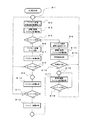
- FIG. 1 is an example 1 of a block diagram of an underwater light.
- the underwater light 50 is a product that can be separated and detached from the battery-mounted device 53 and the power receiving device 51 mounted on the light unit.
- the power receiving device 51 mounted on the light unit has various types of lights and can be replaced as appropriate.
- the battery of the battery-mounted device 53 is exhausted, it is fully charged separately prepared in advance. If you have the battery-equipped device 53, you can continue to use the light underwater by replacing it.
- the conventional underwater light has various problems.
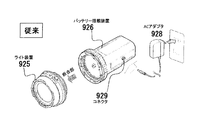
- the configuration diagram of the conventional underwater light of FIG. 3 will be described.
- the conventional underwater light it is necessary to take it out of the water, wipe off the moisture of the fitting portion or the connecting portion sufficiently, and then replace the battery mounting device 926 and the light device 925. This is because there were factors such as leakage of electricity and deterioration of contact life such as electric leakage and salt biting of the connector when seawater got on.
- the battery can be charged by connecting the AC adapter 928 to the connector 929.
- This connector 929 must be used with a waterproof lid when underwater.
- a wireless power feeding mechanism is used to solve this problem. Furthermore, we devised a way to reduce the cost. I will explain it briefly. Configuration of the underwater light of FIG. 1 There is no electrical connector in the joint portion of FIG. Instead, the alignment joint and the wireless power receiving side 55 of the battery mounting device 53 have a built-in wireless power receiving coil that functions as wireless power feeding, and the wireless power receiving side 54 of the power receiving device 51 mounted on the light unit , The wireless power receiving coil is built-in. It is preferable to use a material which is mainly composed of resin and is not easily corroded for the joint portion and the joint portion.
- An LED 56 is provided in the joint portion of FIG.
- the LED When replacing the battery-equipped device and the light device in deep water such as deep diving, it is usually a pitch-black place where sunlight does not reach. At this time, if the only light goes out due to the battery running out, it will be a matter of life and death. Therefore, even if the LED runs out by arranging the LED in the joint part, it is lit by a small capacity battery for several minutes to facilitate replacement.
- the LED is installed in the mating portion, but if the purpose is to make the light device easier to see, it may be installed anywhere in the light device, not in the mating portion.
- the backup battery for example, a supercapacitor or the like may be used.
- a light emitting guide portion made of a phosphorescent material 52 is provided at an appropriate position in the mating portion.
- the phosphorescent material is a material that shines faintly for a while even without a light source when it is exposed to a certain light source. Even if the backup battery for the LED of the main unit is exhausted, the light emitting guide unit that glows with the light of the LED shines faintly for a while, so safety can be doubled.
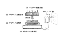
- FIG. 2 is an example 2 of a configuration diagram of an underwater light.
- the battery-mounted device 53 of FIG. 1 when the battery-mounted device 53 of FIG. 1 is connected to the power receiving device 51 mounted on the light unit, the battery-mounted device 53 supplies wireless power, and the battery-mounted device 56 and the battery charging device 57 of FIG. When connected to, the battery-mounted device 56 has a wireless power receiving function. As a result, the battery-mounted device 56 does not have to be provided with a connector and a function for charging, which contributes to cost reduction and convenience.
- the battery-mounted device 56 has a built-in wireless power receiving / powering coil that functions as a wireless power receiving / power receiving side 58 on the wireless power receiving / feeding side 58, and wirelessly on the wireless power feeding side 59 of the battery charging device 57. It has a built-in power supply coil.
- the battery charging device 57 has a structure having protrusions by utilizing the dent of the battery mounting device 56. Unlike the light part, it does not need to be screwed in, and the battery-mounted device 56 is combined in a standing manner.
- the battery charging device 57 is connected to the AC adapter 60 to supply power. In the battery charging device 57, the connector portion with the AC adapter 60 does not need to be specially waterproofed.
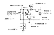
- the power supply device 10 of FIG. 4 has a power supply coil 11, a resonance capacitor 14 that constitutes a resonance circuit together with the power supply coil 11, a switch circuit 12 for turning power on and off the power supply coil 11, and a frequency supplied to the power supply coil 11. It includes a frequency adjusting circuit 15 for adjusting (for example, a circuit for adjusting a capacitor), a resonance state sensor 16 for detecting a resonance state, and a power supply 18.
- a frequency adjusting circuit 15 for adjusting for example, a circuit for adjusting a capacitor
- a resonance state sensor 16 for detecting a resonance state
- a power supply 18 for detecting a resonance state
- the features on the power supply device 10 side are listed. First, the feeding coil 11 and the resonance condenser 14 form a parallel resonance circuit. Second, there is one switch. Thirdly, the control circuit 17 controls the frequency adjustment circuit 15 and the switch circuit 12, and controls the frequency and the power supply time. Fourth, it has a resonance state sensor 16 that detects a resonance state (mainly a frequency shift
- FIG. 4 shows a basic circuit diagram (close to a block diagram).
- a power feeding coil 11 is provided to generate an electromagnetic wave to cause electromagnetic induction.
- At least the electric circuit of the power feeding device 10 is provided with a resonance capacitor 14 and a power supply 18, and forms a resonance relationship with the power receiving coil 1 of the power receiving device 2 at a constant frequency.
- the frequency at this time is referred to as a resonance frequency, and generally, a frequency from 100 kHz to 500 kHz is used.
- the resonance frequency used in the present invention is not particularly limited.
- the resonance frequency slightly deviates depending on the positional relationship and state of the power receiving device 2. For example, the situation changes depending on the position and inclination of the power receiving coil of the power receiving device 2. Therefore, if the power receiving coil 1 falls within the range of the electromagnetic wave transmitted from the power feeding coil 11 (within the magnetic flux lines shown in FIG. 1), energy can be supplied. The insertion of the power receiving coil 1 into the magnetic flux line affects the power feeding device side in the form of a deviation of the resonance frequency. If the resonance frequency shifts, the efficiency of energy supply decreases. Therefore, the shifted frequency and phase are detected by the resonance state sensor 16 (for example, a circuit including a phase detection circuit using a current sensor and a voltage sensor), and the frequency adjustment circuit 15 is used according to the frequency and phase. The frequency of the power feeding coil 11 is adjusted.
- the frequency adjusting circuit 15 is, for example, a circuit for adjusting the capacitance of the condenser.
- control circuit 17 that is controlled by a program using a microcontroller (integrated circuit including a processor, a memory, and peripheral circuits) or a programmable logic device (an integrated circuit in which an internal logic circuit can be defined / changed). ..
- the control circuit 17 is connected to the resonance state sensor 16 (phase detection circuit).
- the resonance state sensor 16 senses a frequency shift or a phase shift and transmits the signal to the control circuit 17.
- the resonance state sensor 16 detects an abnormal frequency or phase, transmits the signal to the control circuit 17, and the control circuit 17 stops the power supply. It becomes possible.
- a method of checking the heat generation state by temperature detection with a temperature sensor connected to a microcontroller to detect an abnormality and a method of detecting an overvoltage or an overcurrent by using a voltage / current detecting means to detect an abnormality. It is possible to make a safer system by using it together.
- the position of the resonance condenser 14 is at the position of ⁇ .
- a capacitor is connected in series with the feeding coil and is located at the ⁇ position.
- the reference of the resonance frequency can be adjusted by the specification of this condenser.
- the conventional connection method of this circuit is generally called a series resonant circuit.
- a parallel resonance circuit is adopted in the circuit of the power feeding device 10 of the wireless power feeding system in the present invention shown in FIG. 4, a parallel resonance circuit is adopted. In the circuit of FIG. 4, a method of detecting the resonance state can be used without stopping the feeding to the feeding coil 11.
- the wireless power supply system of the present invention is composed of the basic circuit shown in FIG.
- this parallel resonance circuit when SW1 is turned on and a stable resonance state is reached, and then SW1 is turned off, resonance with the power receiving device 2 is performed while the energy stored in the power receiving coil 1 and the capacitor 3 is released.
- the feature is that the power feeding device 10 continues the state.
- the ON / OFF timing of SW1 is controlled by using a PLL (Phase Locked Loop) circuit.
- the frequency adjustment circuit 15 and the control circuit 17 realize power supply of an appropriate frequency based on the transition of the resonance state detected by the resonance state sensor 16 connected in parallel with the power feeding coil 11.
- the resonance state sensor 16 is a sensor that detects the resonance state, and detects the transition of the voltage sensor / current sensor and the phase detection of the resonance frequency.
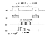
- FIG. 5 is a schematic diagram of a signal waveform of the basic circuit of the power feeding device 10 of FIG.
- FIG. 5A is a waveform of the switch circuit 12 of FIG. 4, which is switched on when it is high. That is, when the switch is turned on, the power supply 18 is supplied, so that the drive state, that is, the drive time. The time when the switch is turned off and not driven is the resonance state, that is, the resonance time.
- the power feeding device 10 is in a resonance state with the power receiving device 2 regardless of whether it is in the driving state or the resonance state. If so, continue to supply energy.
- FIG. 5B is a drive signal.
- the switch circuit 12 When the switch circuit 12 is on, the power supply 18 is turned on.
- FIG. 5C is a sampling signal detected by the resonance state sensor 16 of FIG. 1, and the signal is turned on a plurality of times during the sampling time to perform detection (sampling).
- FIG. 5D is a received signal input to the resonance state sensor 16 of FIG. This signal indicates the state of the feeding coil 11 in the resonant state. Although this signal waveform is shown briefly, it is a signal having frequency characteristics, and it is also possible to measure frequency components. Mainly, the voltage is converted into a digital value by an AD conversion circuit or the like, and information is sent to the control circuit 17 in FIG.
- the control circuit 17 adjusts the frequency at the time of power supply in cooperation with the frequency adjustment circuit 15 by judging these in a complex manner. Occasionally, the frequency is intentionally shifted back and forth to examine the change in the state shown in FIG. 5 (D). Further, when the power receiving device 2 is in a resonance state, the control circuit 17 also adjusts the drive time in consideration of how the voltage in FIG. 5D is reduced.
- executing the detection of the resonance state sensor 16 in FIG. 5C also involves a loss of energy as the power feeding device 10. Therefore, it is possible to suppress the energy loss by performing sampling intermittently, for example, once per second, instead of performing it every time.
- the specifications of the power supply 18, the power supply coil 11, and the resonance frequency are determined according to the size of the energy to be sent and the size and height of the area to be fed.
- the resonance capacitor 14 is mainly determined according to the specifications of the reference resonance frequency.
- the circuit of the power receiving device 2 includes a predetermined power receiving coil 1, and at least a condenser 3 and a rectifying circuit 4.
- the condenser 3 may be connected to the power receiving coil 1 in series or in parallel. In the present invention, it is ideal to connect in parallel.
- the power receiving device 2 has an internal battery 5 built-in.
- the internal battery 5 is a rechargeable secondary battery.
- a super capacitor electric double layer capacitor
- the specifications and volume of the power receiving coil 1 and the resonance frequency at this time are set according to the magnitude of the energy to be received, but it is also possible to give priority to the volume to be stored as the power receiving device 2.
- the power receiving device 2 When electromagnetic induction is generated from the power feeding coil 11 of the power feeding device 10 at a predetermined resonance frequency, magnetic flux is generated as shown in FIG.
- the power receiving coil 1 of the power receiving device 2 When the power receiving coil 1 of the power receiving device 2 is inserted at the tip of the magnetic flux line, electrical energy is generated by the electromotive force generated by electromagnetic induction. This energy is recovered and stored in the internal battery 5.
- the power receiving device 2 In the case of a general existing wireless power feeding device, the power receiving device 2 is often provided with a frequency detection circuit and a communication means to the power receiving device 10 that indicates the state of the power receiving device 2. ..
- the power feeding device 10 has a mechanism for transmitting to the power feeding device 10 by a communication means and appropriately adjusting the resonance frequency. In that case, the power receiving device 10 needs a predetermined IC circuit.
- the circuit of the power receiving device 2 is configured by a mechanism that simplifies to the utmost limit. With this simplified configuration, it is possible to discharge while charging, so while the charger is installed inside the electronic device, it is charged by the wireless power supply system, and at the same time it is discharged to the electronic device to generate electric power. It becomes possible to supply.
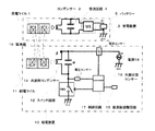
- FIG. 6 is an explanatory diagram of a circuit in which a power feeding unit and a power receiving unit are integrated.
- the wireless power feeding system of the battery-mounted device of the present invention is a wireless power receiving coil that combines a wireless power feeding coil and a wireless power receiving coil.
- the power supply circuit unit and the power reception circuit unit are mounted on one circuit board.
- the power receiving / feeding circuit unit was composed of a power receiving / power supply circuit unit capable of switching between the power supply mode and the power receiving mode by a predetermined switching means.
- the power receiving coil 1 and the power feeding coil 11 shown in FIG. 4 are shared by one power receiving coil 31. Further, it is characterized in that it is a power receiving / feeding circuit in which the circuit part of the power receiving device 2 and the circuit part of the power feeding device 10 are integrated. It is a circuit using the parallel resonance circuit proposed in the present invention, and the resonance capacitor 34 is connected in parallel with the coil.
- the switch SW2 of the switching means 33 is turned on to supply power from the battery, and the SW3 is turned off.
- this parallel resonance circuit when SW1 is turned on and a stable resonance state is reached, and then SW1 is turned off, resonance with the power receiving device is performed while the energy stored in the power receiving / feeding coil 31 and the condenser 34 is released. It is characterized by continuing the state.
- the frequency adjustment circuit 35 and the control circuit 37 realize power supply of an appropriate frequency based on the transition of the resonance state detected by the resonance state sensor 36 connected in parallel with the power receiving / feeding coil 31.
- the resonance state sensor 36 is a sensor that detects a resonance state, and detects a transition between voltage and current, phase detection of a resonance frequency, and the like.
- the state of the circuit in the power receiving mode in which power is received will be described.
- the switch SW2 of the switching means 33 is turned off and the SW3 is turned on. Also, SW1 is turned off. Electrical energy is generated by the electromotive force of the power receiving and feeding coil 31 due to electromagnetic induction. This energy passes through the rectifier circuit 38 and charges the battery 39.
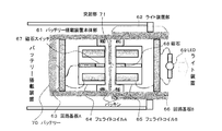
- FIG. 7 is a cross-sectional view of a connection portion between the battery-mounted device and the light device.
- the battery-mounted device main body 61 is provided with a ferrite coil A64 and is connected to the circuit board A63. Here, it is a board on which the wireless power receiving and feeding circuit shown in FIG. 6 is mounted.
- a battery 70 is connected to the circuit board A63.
- the ferrite coil A64 is also referred to as a wireless power receiving / feeding coil.
- the light device unit 62 is provided with a ferrite coil B65 and is connected to the circuit board B66. Here, it is a board on which the wireless power receiving and feeding circuit shown in FIG. 6 is mounted.
- the circuit board B66 is connected to LED69, which is a light.
- a protrusion 71 is provided at the connection between the battery-mounted device and the light device in FIG. 7.
- the battery-mounted device main body 61 is convex
- the light device 62 is concave
- the devices are combined.
- As a waterproof measure there is packing and the like, and the entire integrated portion of the battery-mounted device main body is concave, and the entire integrated portion of the light device 62 is convex. That is, the convex portion of the light device portion 62 is fitted into the concave portion of the battery mounting device main body 61 with the protrusion 71 as the center, or screwed into the recess.
- the ferrite coil A64 and the ferrite coil B65 are arranged so as to face each other with the thickness of the case in between.
- a magnet switch 67 is provided in the battery-mounted device main body 61 and a magnet 68 is provided in the light device 62 in order to detect whether the battery-mounted device main body 61 and the light device 62 are in a combined state. Has been done. At the time of matching, the magnet 68 turns on the magnet switch 67 and acts on the circuit board A63.
- the power supply efficiency of the wireless power supply is constant even if the light device 62 is rotated around the protrusion 71 in the wireless power supply. is there. Therefore, if there is a function of detecting the rotation position when the light device unit 62 is rotated, it is possible to provide a function of changing the intensity of the light depending on the rotation direction. Furthermore, it is possible to change the color of the light, or change the lighting and blinking, instead of changing the intensity of the light. Since several types of lights can be replaced on-site, it can be changed to a light for a suitable purpose and can be operated with multiple functions.
- the meaning of detecting the integrated state is to stop the wireless power supply when the integrated state is not performed, and to reduce the battery consumption.
- this switch mechanism should be provided. Is preferable.
- a method that does not use a magnet switch is also disclosed in the present invention, but will be described later.
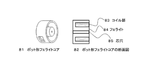
- FIG. 8 is a block diagram of the ferrite coil.
- the ferrite coils A and B of FIG. 7 are intentionally used as a pot-shaped ferrite core 81.
- This core has a structure that does not leak magnetic flux from the outside of the pot shape, and even when exposed to a conductive environment (metal or seawater), the leakage flux can be further suppressed. If the leakage magnetic flux is suppressed, the power supply efficiency is improved and the safety is improved. Further, during wireless power supply, the coil portion 83 may generate some heat, but the pot-shaped ferrite core has a heat dissipation effect as compared with the ferrite cores of other shapes.
- a pot-shaped ferrite core 81 As a schematic diagram of the pot-shaped ferrite core 81, a pot-shaped ferrite core 81 composed of a coil portion 83 wound by an electric wire, a ferrite 84, and a core hole 85 when a hole is formed in the center. is there.
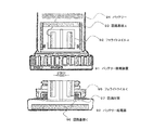
- FIG. 9 is a cross-sectional view of a connection portion between the battery-mounted device and the battery charging device.
- the battery and the mounting device 91 are provided with a ferrite coil A92 and are connected to the circuit board A93.
- the circuit board A93 is connected to the battery 94.
- the ferrite coil A92 is also referred to as a wireless power receiving / feeding coil.
- the battery power supply device 92 is provided with a ferrite coil C95 and is connected to the circuit board C96. Power is supplied to the circuit board C96 from an AC adapter or the like.
- the battery power supply device 92 has a drip-proof measure 97 mechanism on the assumption that the battery and the on-board device 91 are to be charged with water droplets on them.
- the drip-proof measure 97 is a case of a battery power supply device 92 made of a sponge-like material that absorbs water droplets and provided with air holes for natural evaporation. Further, as another method of the drip-proof measure 97, when the battery and the mounting device 91 are combined, the water droplets attached to the battery and the mounting device 91 may be pushed out and the water droplets may flow to the dish-shaped drip-proof measure 97. ..
- the dish-shaped drip-proof measure 97 is provided with a hole for allowing water droplets to escape in the case of the battery and the mounting device 91.
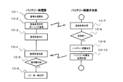
- FIG. 10 is a processing flow diagram of the battery-mounted main body.
- the battery-equipped main unit processes both wireless power supply and wireless power reception functions with the same coil and circuit. I will explain it step by step.
- the initialization process is various processes executed when the power is turned on.
- 8-2 is a power supply mode switching process in the standby state of wireless power supply.
- the wireless power supply process is performed in the low voltage drive state (8-3). In this state, for example, in addition to lowering the power supply voltage itself, the power supply is intermittently performed by taking a long time when the power supply is not performed to suppress the power consumption.
- the resonance state sensor 16 detects whether or not there is a power receiving side of the light device, and the sensor determines whether or not it is equal to or higher than the threshold value by the reaction 8-4. If the sensor does not respond, switch to wireless power receiving mode (8-6). Next, the wireless power receiving process of 8-7 is performed. From the detection of the resonance state sensor 16, it is determined by the reaction 8-8 to the sensor whether or not it is equal to or higher than the threshold value. From the next, it is an iterative process. 8-10 Wireless power reception processing is performed, and the sensor is judged by 8-11. Then, if stable power reception is performed from the reaction of the sensor, the battery power reception process is performed at 8-12. Returning to 8-9, it is repeated as long as it reacts to the sensor.
- the process returns to 8-1. If the 8-4 sensor responds, switch to the normal power supply mode of 8-5 wireless power supply. At 8-13, wireless power supply processing is performed with high voltage drive. A predetermined abnormality detection process is performed on 8-14. As a result of the abnormality detection, if the object is wirelessly supplied with power (8-15), the process returns to 8-16, otherwise the process returns to 8-1. If the object is normal, wireless power supply processing is performed at 8-17 with high voltage drive. Then, when the sensor stops responding, it returns to 8-1, and if there is a response, it returns to 8-16 and repeats the process. In this way, the mechanism for switching the wireless power supply / reception mode of the battery-mounted main unit has been described in the flow chart.
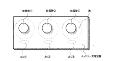
- FIG. 11 is a diagram of an example of a battery charging device.
- This battery charging device has a configuration in which the battery power supply device described in FIG. 9 is provided. In this way, it is a charging device that can charge the battery of three main bodies equipped with batteries at the same time.
- Each power supply is equipped with an LED status indicating that power is being supplied.
- each power supply unit is equipped with a groove, and the groove is waterproofed so that water droplets and the like are absorbed and discharged during power supply.
- FIG. 12 is a flow chart of an example of communication processing. Communication processing can be performed by a predetermined method during wireless power supply and wireless power reception. This method will be described later, but here, the execution steps will be described step by step in a flow diagram.
- the communication process is started at 10-1. Here, the process of storing the communication contents in the memory is mainly performed.
- the communication transmission process is performed. Communication transmission communicates in a polling format.
- the communication reception wait is performed. If communication is successful, the response value will be returned, so wait for reception for a certain period of time.
- the communication reception process is performed at 10-4.
- the 10-5 full charge determination process is performed.
- the LED in FIG. 11 is changed from red lighting to green lighting.
- the battery-mounted main body There is a 10-7 communication reception process for receiving the communication content transmitted from the communication process of 10-2.
- the battery capacity is measured, the battery capacity value of 10-10 is returned, and the response is transmitted.
- this communication means two-way communication, it is possible to have various functions.
- the power receiving device mounted on the light unit is equipped with a means for recording the amount of light emitted, and when the main body equipped with the battery and the light unit are connected to perform wireless power supply, the numerical value of the amount of light emitted is received by the communication means. It is also possible to store it in the memory of the main body of the battery.
- the wireless power supply system of the present invention has a configuration particularly suitable for an underwater camera. It can also be applied not only to water, but also to dusty environments and products that are safe for children to handle.
- a light that wants to freely rotate in the direction of rotation can be connected to the main body equipped with a battery, and is not limited to the light, but can be applied to any destination (energy consumption circuit section) that wants to supply power.
Abstract
[Problem] To replace a light unit in water and supply power without electrical contact. [Solution] A composite wireless power feeding system comprising: a first wireless power feeding system having a first power feeding coil, a first power feeding circuit unit, a first power receiving coil, a first power receiving circuit unit, and a first battery; and a second wireless power feeding system having a second power feeding coil, a second power feeding circuit unit, a second power receiving coil, a second power receiving circuit unit, and an energy consuming circuit unit, wherein the first power receiving coil also serves as the second power feeding coil. The first battery is a power source that generates electromagnetic waves in the second power feeding coil. Switching between the power-feeding mode and the power-receiving mode is possible using a prescribed mode-switching means for which the second power feeding circuit unit and the first power receiving circuit unit are mounted on one circuit board. Using the mode switching means, when the power-feeding mode is enabled, energy is supplied to the energy consuming circuit unit, and when the power-receiving mode is enabled, the first battery is charged. Fitting is done without electrical contacts.
Description
本発明は、ワイヤレス給電システム、特に共振方式の誘導結合により給電するシステムに関する。さらに言えば、バッテリー搭載のライトに利用されるシステムに関する。
The present invention relates to a wireless power feeding system, particularly a system that supplies power by inductive coupling of a resonance method. Furthermore, it concerns the system used for battery-powered lights.
水中ライトにおいて、専用のバッテリー搭載装置に着脱し、複数種類のライトを取り替え利用する水中ライトがある。
一方、ワイヤレス給電の技術においては、種々の方法、方式に基づいた装置が、数多く提案されている。その中でも、電磁誘導を使った方法は、広く一般的に知られている。 Among underwater lights, there are underwater lights that can be attached to and detached from a dedicated battery-equipped device to replace multiple types of lights.
On the other hand, in the wireless power feeding technology, many devices based on various methods and methods have been proposed. Among them, the method using electromagnetic induction is widely and generally known.
特許文献1には、電磁界共振による結合で比較的遠距離に給電できるワイヤレス給電にあって、より幅広い周波数の利用拡大を可能とするワイヤレス給電の方法及び給電システムが開示されている。電磁界共振ワイヤレス給電方法は、送電デバイスの送電回路と受電デバイスの受電回路とが電磁界共振で結合されるワイヤレス給電にあって、送電デバイスを、電源2に異なる2つの周波数成分f1及びf2を用い、送電回路の共振周波数をf1及び/又はf2とし、送電回路の条件を周期的に変化させて電流及び/又は電圧の安定しない電気的過渡状態とし、受電デバイスを、受電回路の共振周波数をうなり現象による(f2-f1)又は(f1+f2)とし、該(f2-f1)又は(f1+f2)の周波数による電力を負荷に供給することを特徴とするものである。
Patent Document 1 discloses a wireless power feeding method and a power feeding system that can expand the use of a wider range of frequencies in wireless power feeding that can supply power to a relatively long distance by coupling by electromagnetic field resonance. The electromagnetic field resonance wireless power feeding method is in wireless power feeding in which the power transmission circuit of the power transmission device and the power reception circuit of the power reception device are coupled by electromagnetic field resonance, and the power transmission device is supplied with two different frequency components f1 and f2. In use, the resonance frequency of the power transmission circuit is set to f1 and / or f2, the conditions of the power transmission circuit are changed periodically to bring the current and / or voltage into an unstable electrical transient state, and the power receiving device is set to the resonance frequency of the power receiving circuit. It is characterized in that it is determined to be (f2-f1) or (f1 + f2) due to a roaring phenomenon, and power is supplied to the load at the frequency of (f2-f1) or (f1 + f2).
特許文献2には、電力伝送デバイスとしてループコイルを用い、非常にシンプルなワイヤレス給電器が開示されている。送電装置に設けられている送電ループコイルは、直流電源から電気エネルギーを取り出して、周期的に変化する電磁界共鳴エネルギーを空間に発生させる。受電器に設けられている受電ループコイルは、周期的に変化する電磁界共鳴エネルギーを空間から電気エネルギーとして取り出して負荷に電力を供給する。送電ループコイルと受電ループコイルとは電磁界共鳴結合し、送電装置から受電器へワイヤレスで電力が給電される。
Patent Document 2 discloses a very simple wireless power supply using a loop coil as a power transmission device. The power transmission loop coil provided in the power transmission device extracts electrical energy from the DC power source and generates cyclically changing electromagnetic field resonance energy in the space. The power receiving loop coil provided in the power receiving device extracts the electromagnetic field resonance energy that changes periodically as electric energy from the space and supplies electric power to the load. The power transmission loop coil and the power reception loop coil are electromagnetically resonantly coupled, and power is wirelessly supplied from the power transmission device to the power receiver.
特許文献3には、複数の中継装置を備えるワイヤレス給電システムであって、中継装置による電力の伝送効率の低下を抑制するワイヤレス給電システムが開示されている。給電される電力を送電する送電装置と、前記送電装置から送電された前記電力を中継する複数の中継装置と、前記中継装置で中継された前記電力を受電する受電器と、前記中継装置を経由して前記送電装置から前記受電器に前記電力を伝送する複数の伝送経路において前記電力の伝送効率が最も高くなる前記伝送経路で電力伝送するように前記中継装置を制御する制御装置と、を備えるものである。
Patent Document 3 discloses a wireless power supply system including a plurality of relay devices, which suppresses a decrease in power transmission efficiency due to the relay devices. Via a power transmission device that transmits the power to be supplied, a plurality of relay devices that relay the power transmitted from the power transmission device, a power receiver that receives the power relayed by the relay device, and the relay device. A control device for controlling the relay device so as to transmit power in the transmission path having the highest transmission efficiency of the power in a plurality of transmission paths for transmitting the power from the power transmission device to the power receiver is provided. It is a thing.
特許文献4には、磁気共振型ワイヤレス給電システムの電力の伝送効率を上昇させる技術が開示されている。磁気共振型ワイヤレス給電システムは、交流電源と、交流電源に接続される電圧変換用コイルと、送電側LC回路と、受電側LC回路と、インピーダンス変換用コイルと、インピーダンス変換用コイルに接続される負荷と、負荷に並列に接続される伝送効率調整用コンデンサーとを備える。送電側LC回路は、電圧変換用コイルの近傍に配置され、電圧変換用コイルとの間の電磁誘導により励起される送電側コイル及び送電側コンデンサーを有する。受電側LC回路は、送電側コイルと共振する受電側コイル及び受電側コンデンサーを有する。インピーダンス変換用コイルは、受電側LC回路の近傍に配置され、受電側コイルとの間の電磁誘導により励起される。伝送効率調整用コンデンサーは、交流電源から負荷への電力の伝送効率を上昇させるような容量を有する。
Patent Document 4 discloses a technique for increasing the power transmission efficiency of a magnetic resonance type wireless power feeding system. The magnetic resonance type wireless power supply system is connected to an AC power supply, a voltage conversion coil connected to the AC power supply, a transmission side LC circuit, a power reception side LC circuit, an impedance conversion coil, and an impedance conversion coil. It includes a load and a transmission efficiency adjusting capacitor connected in parallel with the load. The power transmission side LC circuit has a power transmission side coil and a power transmission side capacitor which are arranged in the vicinity of the voltage conversion coil and are excited by electromagnetic induction with the voltage conversion coil. The power receiving side LC circuit has a power receiving side coil and a power receiving side capacitor that resonate with the power transmitting side coil. The impedance conversion coil is arranged in the vicinity of the power receiving side LC circuit and is excited by electromagnetic induction with the power receiving side coil. The transmission efficiency adjusting capacitor has a capacity that increases the transmission efficiency of electric power from the AC power supply to the load.
Patent Document 4 discloses a technique for increasing the power transmission efficiency of a magnetic resonance type wireless power feeding system. The magnetic resonance type wireless power supply system is connected to an AC power supply, a voltage conversion coil connected to the AC power supply, a transmission side LC circuit, a power reception side LC circuit, an impedance conversion coil, and an impedance conversion coil. It includes a load and a transmission efficiency adjusting capacitor connected in parallel with the load. The power transmission side LC circuit has a power transmission side coil and a power transmission side capacitor which are arranged in the vicinity of the voltage conversion coil and are excited by electromagnetic induction with the voltage conversion coil. The power receiving side LC circuit has a power receiving side coil and a power receiving side capacitor that resonate with the power transmitting side coil. The impedance conversion coil is arranged in the vicinity of the power receiving side LC circuit and is excited by electromagnetic induction with the power receiving side coil. The transmission efficiency adjusting capacitor has a capacity that increases the transmission efficiency of electric power from the AC power supply to the load.
特許文献5には、あらゆる受電機器に対し、汎用性が高く応用性の高いワイヤレス給電システムが開示されている。ワイヤレス給電システムは、給電部を有する給電台から受電部を搭載した受電機器へ無接点で電力を給電するワイヤレス給電システムであって、給電台と受電機器との間に中間部材を備えたことを特徴とする。受電機器が異なった場合であっても、単一の給電器で給電を行うことができる。また、受電機器は、給電中に受電機器の配置を変化させることができるため、汎用性が高く応用性の高いワイヤレス給電システムを提供することができる。
Patent Document 5 discloses a highly versatile and highly applicable wireless power supply system for all power receiving devices. The wireless power supply system is a wireless power supply system that supplies power from a power supply stand having a power supply unit to a power receiving device equipped with a power receiving unit without contact, and has an intermediate member between the power supply stand and the power receiving device. It is a feature. Even if the power receiving equipment is different, power can be supplied by a single power supply. Further, since the power receiving device can change the arrangement of the power receiving device during power supply, it is possible to provide a highly versatile and highly applicable wireless power feeding system.
特許文献6には、ワイヤレス給電器において、給電器と受電器の方式や大きさや形状に不整合がある場合でも、給電器から受電器に給電できるようにする装置が開示されている。給電器が給電できる受電器の範囲を広くすることができる。給電器と受電器との間に、着脱自在な変換器を設ける。変換器は、磁気回路や電気的な受動素子や再給電などを用いて、給電器からの受電器の見かけの方式や大きさや形状が適合するように機能する。
Patent Document 6 discloses a device that enables power to be supplied from the power supply to the power receiver even when there is a mismatch in the method, size, and shape of the power supply and the power receiver in the wireless power supply. The range of the power receiver that the power supply can supply can be widened. A detachable converter is provided between the power supply and the power receiver. The converter functions by using a magnetic circuit, an electric passive element, re-feeding, etc., so that the apparent method, size, and shape of the power receiving device from the feeding device match.
特許文献7には、送信コイルと受信コイルの結合度が変化しても、高効率な電力伝送を行うワイヤレス給電の技術が開示されている。ワイヤレス給電器は、共振回路およびマルチトーン電源を備え、電界、磁界、電磁界のいずれかを含む電力信号を送信する。共振回路は、直列に接続された送信コイルおよび共振用キャパシタを含む。マルチトーン電源は、複数の周波数の正弦波信号を重ね合わせたマルチトーン信号を、共振回路に出力する。
Patent Document 7 discloses a wireless power feeding technique that performs highly efficient power transmission even if the degree of coupling between the transmitting coil and the receiving coil changes. The wireless power supply includes a resonant circuit and a multitone power supply and transmits a power signal including an electric field, a magnetic field, or an electromagnetic field. The resonance circuit includes a transmission coil and a resonance capacitor connected in series. The multitone power supply outputs a multitone signal obtained by superimposing sinusoidal signals of a plurality of frequencies to a resonance circuit.
特許文献8には、磁気共振型のワイヤレス給電における電力伝送効率を高める技術が開示されている。ワイヤレス給電器は、キャパシタと給電コイルを共振させることにより、給電コイルと受電コイルを磁気共振させる。このときの共振周波数をfとする。ワイヤレス給電器は、スイッチングトランジスタとスイッチングトランジスタを交互にオン・オフさせることにより、給電コイルに共振周波数fの交流電力を供給する。
Patent Document 8 discloses a technique for improving power transmission efficiency in magnetic resonance type wireless power supply. The wireless power supply magnetically resonates the power feeding coil and the power receiving coil by resonating the capacitor and the power feeding coil. Let f be the resonance frequency at this time. The wireless power supply supplies AC power having a resonance frequency f to the power supply coil by alternately turning on / off the switching transistor and the switching transistor.
特許文献9には、磁場共振型のワイヤレス給電において、給電電力を効率的に制御する技術が開示されている。ワイヤレス給電器は、給電コイルと受電コイルの磁場共振現象に基づき、給電コイルから受電コイルにワイヤレス給電するための装置である。送電制御回路は、給電コイルに駆動周波数にて交流電力を供給する。これにより、給電コイルから受電コイルに交流電力を給電させる。位相検出回路は、交流電力の電圧位相と電流位相の位相差を検出する。具体的には、信号T2がハイレベル第1検出期間と信号S2がハイレベルとなる第2検出期間を比較し、それらが重複する期間の長さを検出することにより、位相差を検出する。
Patent Document 9 discloses a technique for efficiently controlling the power supply in the magnetic field resonance type wireless power supply. The wireless power feeder is a device for wirelessly feeding power from the power feeding coil to the power receiving coil based on the magnetic field resonance phenomenon of the power feeding coil and the power receiving coil. The power transmission control circuit supplies AC power to the power feeding coil at the drive frequency. As a result, AC power is supplied from the power feeding coil to the power receiving coil. The phase detection circuit detects the phase difference between the voltage phase and the current phase of AC power. Specifically, the phase difference is detected by comparing the first detection period in which the signal T2 is at the high level and the second detection period in which the signal S2 is at the high level and detecting the length of the period in which they overlap.
特許文献10には、回路規模、コストの増大を抑止でき、電力損失を低減でき、しかも給電側、受電側双方のインピーダンス調整を行うことが可能な給電器、受電器、およびワイヤレス給電システムが開示されている。給電器は、給電すべき電力を生成する電力生成部と、電力生成部で生成される電力が給電されるコイルにより形成される給電素子と、電磁誘導により結合する共鳴素子と、給電側のインピーダンスを検出するインピーダンス検出部と、制御信号に応じて電力の給電素子の給電点におけるインピーダンス整合機能を含む可変整合部と、インピーダンス特性推定情報を参照テーブルとして格納する記憶部と、少なくとも検出されたインピーダンス情報と、憶部の参照テーブルの情報から可変整合部の調整すべき状態を求め、求めた状態となるように制御信号を可変整合部に出力する制御部と、を有する。
Patent Document 10 discloses a power feeder, a power receiver, and a wireless power supply system capable of suppressing an increase in circuit scale and cost, reducing power loss, and adjusting impedance on both the power supply side and the power reception side. Has been done. The feeder includes a power generator that generates power to be fed, a feed element formed by a coil to which the power generated by the power generator is fed, a resonance element that is coupled by electromagnetic induction, and impedance on the feed side. An impedance detection unit that detects the above, a variable matching unit that includes an impedance matching function at the feeding point of the power feeding element according to the control signal, a storage unit that stores impedance characteristic estimation information as a reference table, and at least the detected impedance. It has an information and a control unit that obtains a state to be adjusted of the variable matching unit from the information in the reference table of the memory unit and outputs a control signal to the variable matching unit so as to obtain the obtained state.
特許文献11には、磁場共振型のワイヤレス給電において、負荷電圧を安定させる技術が開示されている。給電コイルから受電コイルには磁気共振により電力が伝送される。VCOは、スイッチングトランジスタQ1とスイッチングトランジスタQ2を駆動周波数foにて交互にオン・オフさせ、給電コイルに交流電力を供給し、給電コイルから受電コイルに交流電力を供給する。位相検出回路は電流位相と電圧位相の位相差を検出し、VCOはこの位相差がゼロとなるように駆動周波数foを調整する。負荷電圧が変化したときには電圧位相の検出値が調整され、結果として駆動周波数foが調整される。
Patent Document 11 discloses a technique for stabilizing a load voltage in a magnetic field resonance type wireless power supply. Electric power is transmitted from the feeding coil to the receiving coil by magnetic resonance. The VCO alternately turns on / off the switching transistor Q1 and the switching transistor Q2 at the drive frequency fo, supplies AC power to the feeding coil, and supplies AC power from the feeding coil to the receiving coil. The phase detection circuit detects the phase difference between the current phase and the voltage phase, and the VCO adjusts the drive frequency fo so that the phase difference becomes zero. When the load voltage changes, the detected value of the voltage phase is adjusted, and as a result, the drive frequency fo is adjusted.
特許文献12には、高いQ値を実現可能な受電回路が開示されている。ワイヤレス受電器は、ワイヤレス給電器から送出される電界、磁界、電磁界のいずれかを含む電力信号S1を受信する。受信コイルL2は、電力信号S1を受信するためのものである。電力保存用キャパシタC3は、その第1端子の電位が固定される。第1スイッチSW1、第2スイッチSW2は、受信コイルL2と閉ループを形成するように順に直列に接続され、それらの接続点N1は電力保存用キャパシタC3の第2端子と接続される。第3スイッチSW3、第4スイッチSW4は、第1スイッチSW1、第2スイッチSW2と並列な経路に順に直列に設けられ、それらの接続点N2の電位が固定される。
Patent Document 12 discloses a power receiving circuit capable of realizing a high Q value. The wireless power receiver receives a power signal S1 including any of an electric field, a magnetic field, and an electromagnetic field transmitted from the wireless power supply. The receiving coil L2 is for receiving the power signal S1. The potential of the first terminal of the power storage capacitor C3 is fixed. The first switch SW1 and the second switch SW2 are connected in series in order so as to form a closed loop with the receiving coil L2, and their connection points N1 are connected to the second terminal of the power storage capacitor C3. The third switch SW3 and the fourth switch SW4 are provided in series in the path parallel to the first switch SW1 and the second switch SW2 in order, and the potential of their connection point N2 is fixed.
特許文献13には、磁界共鳴型においてより広帯域な周波数特性を得ることが可能な給電器、受電器、およびワイヤレス給電システムが開示されている。給電器は、給電すべき電力を生成する電力生成部と、電力生成部で生成される電力が給電される給電素子と、多段に配置され、互いに磁界共鳴関係をもって結合する複数の共振素子を有し、複数の共振素子の一つの共振素子は、給電素子により電磁誘導により結合する。
Patent Document 13 discloses a power feeder, a power receiver, and a wireless power supply system capable of obtaining a wider band frequency characteristic in a magnetic field resonance type. The power feeder has a power generation unit that generates the power to be supplied, a power supply element to which the power generated by the power generation unit is supplied, and a plurality of resonance elements that are arranged in multiple stages and are coupled to each other in a magnetic field resonance relationship. However, one resonance element of the plurality of resonance elements is coupled by electromagnetic induction by the feeding element.
特許文献14には、電力伝送デバイスとしてループコイルを用いるワイヤレス給電装置が開示されている。具体的には、送電装置に設けられている送電ループコイルは、直流電源から電気エネルギーを取り出して、周期的に変化する電磁界共鳴エネルギーを空間に発生させる。受電装置に設けられている受電ループコイルは、周期的に変化する電磁界共鳴エネルギーを空間から電気エネルギーとして取り出して負荷に電力を供給する。送電ループコイルと受電ループコイルとは電磁界共鳴結合し、送電装置から受電装置へワイヤレスで電力が給電される。
Patent Document 14 discloses a wireless power feeding device that uses a loop coil as a power transmission device. Specifically, the power transmission loop coil provided in the power transmission device extracts electrical energy from the DC power source and generates cyclically changing electromagnetic field resonance energy in the space. The power receiving loop coil provided in the power receiving device extracts the electromagnetic field resonance energy that changes periodically as electric energy from the space and supplies power to the load. The power transmission loop coil and the power reception loop coil are electromagnetically resonantly coupled, and power is wirelessly supplied from the power transmission device to the power reception device.
図3に示すのは、従来の水中ライトの構成図である。基本的には、水中でライトを取り替える事はできず、嵌合部の電気接点に水が入らないように防水する必要があり、浮上後に着脱する場合は水分が電気接点に付着しないように注意する必要がある。
バッテリー搭載装置は、バッテリーが内蔵されている本体である。これに、ライト装置を篏合部において合体する事で、本体のバッテリーの電力でライトを光らせる事ができる。ライト装置は、数種類が用意され、例えば、遠くまで光らせるスポットビームなライトや、広範囲を光らせるワイドビームなライトなどがある。それぞれバッテリーの消耗具合も異なる。この篏合部には、電気的に接触する事で接続される接続コネクタがあり、ライト装置がバッテリー搭載装置に、ねじ込んでしっかり取り付けられる事で、電気的に接続状態となる。この時、海水など水分が篏合部に残っていると接続コネクタや、防水のパッキンなどの寿命を早めるとされ、十分に水分をふき取ってから篏合しなければならない。バッテリー搭載装置には、コネクタが具備され、ACアダプタが接続されて、バッテリーを充電する事ができる。コネクタには専用の蓋が用意され、ACアダプターを接続しない時には蓋をして防水する必要がある。 FIG. 3 is a configuration diagram of a conventional underwater light. Basically, the light cannot be replaced underwater, it is necessary to waterproof it so that water does not enter the electrical contacts of the fitting part, and when attaching and detaching after ascending, be careful not to let water adhere to the electrical contacts. There is a need to.
The battery-mounted device is a main body having a built-in battery. By combining this with a light device at the joint, the light can be made to shine with the power of the battery of the main body. Several types of light devices are prepared, for example, a spot beam light that illuminates a long distance and a wide beam light that illuminates a wide range. The degree of battery consumption is also different for each. This fitting part has a connection connector that is connected by electrical contact, and when the light device is screwed into the battery-mounted device and firmly attached, it becomes electrically connected. At this time, if water such as seawater remains in the mating part, it is said that the life of the connector and the waterproof packing will be shortened, and it is necessary to wipe off the water sufficiently before mating. The battery-mounted device is provided with a connector, and an AC adapter can be connected to charge the battery. A special lid is prepared for the connector, and it is necessary to cover it to make it waterproof when the AC adapter is not connected.
電子機器には、バッテリーを内蔵して用いるものがある。そのようなバッテリーは、放電して消耗すると、専用のACアダプタなどに接続するなどして充電する必要がある。
バッテリー搭載の本体とライト部が着脱可能な水中ライトの場合、海水等の水滴にさらされる装置では、バッテリーの交換や、ライトの交換は、水中ではできず、十分水滴をふき取った状態で行わなければならない。接続コネクタ部からの漏電や寿命を速める問題が生じる。 Some electronic devices have a built-in battery. When such a battery is discharged and consumed, it is necessary to charge it by connecting it to a dedicated AC adapter or the like.
In the case of an underwater light with a detachable body and light part, it is not possible to replace the battery or the light in a device exposed to water droplets such as seawater underwater, so the water droplets must be wiped off sufficiently. Must be. There are problems such as electric leakage from the connector and shortening the service life.
バッテリー搭載装置では、ライトへの給電と、バッテリーへの充電の為の受電の役割が必要で、それぞれ各々のコネクタ部を具備している。水中での動作を前提とした場合、コネクタ部のかわりにワイヤレス給電で電力を供給する方法が考えられるが、コネクタ部がライトへの給電とバッテリーへの充電の2種類がある仕組みは、利便性が悪くコストアップ要因である。
The battery-equipped device needs to supply power to the light and receive power to charge the battery, and each has its own connector. Assuming operation in water, a method of supplying power by wireless power supply instead of the connector part can be considered, but it is convenient that the connector part has two types of power supply to the light and charging to the battery. Is bad and is a factor of cost increase.
ワイヤレス給電のために、共振回路を用いることがある。給電装置の側の共振回路は、直列共振回路とするか、並列共振回路とするかの選択がなされる。直列共振回路は、大容量のエネルギーを送りやすい反面、損失が大きい。一方、並列共振回路は、その逆であって、比較的小容量のエネルギーを送るのに用いられ、安定した共振状態を作りやすいという特徴を持つ。
A resonance circuit may be used for wireless power supply. The resonance circuit on the power feeding device side is selected to be a series resonance circuit or a parallel resonance circuit. The series resonance circuit tends to send a large amount of energy, but has a large loss. On the other hand, the parallel resonance circuit is the opposite, and is used to send a relatively small amount of energy, and has a feature that it is easy to create a stable resonance state.
従来の一般的なワイヤレス給電では、給電装置側に直列共振回路を採用する。また、一般的には、共振状態を検出して、周波数を調整することを行うが、給電装置側では、検出用の受信コイルを用いたり、給電と受信を切り替えたりすることにより、共振状態の検出そして周波数調整を実現している。さらに、受電装置側も、共振状態を検出して、その情報を、なんらかの通信方法で、給電装置側に送る(Qi規格など)。こうした仕組みは、コストアップ要因が多く存在している。
In the conventional general wireless power supply, a series resonance circuit is adopted on the power supply device side. Further, generally, the resonance state is detected and the frequency is adjusted, but on the power feeding device side, the resonance state is changed by using a receiving coil for detection or switching between feeding and receiving. It realizes detection and frequency adjustment. Further, the power receiving device side also detects the resonance state and sends the information to the power feeding device side by some communication method (Qi standard, etc.). There are many cost-increasing factors in such a mechanism.
本発明は、バッテリー搭載の本体とライト部が着脱可能な水中ライトにて、海水等の水分が電気接点に付着して接点不良を起こしてしまう課題を解決することを目的とし、水中でライト部の交換ができ、電気的に無接点な状態で、電力を供給できるシステムを提供することを目的とする。
An object of the present invention is to solve a problem that moisture such as seawater adheres to an electric contact and causes a contact failure in an underwater light in which a main body equipped with a battery and a light portion can be attached and detached. The purpose is to provide a system that can be replaced and can supply electric power in an electrically non-contact state.
本発明に係るワイヤレス給電システムは、電磁波を発生する第1の給電コイルと、
該第1の給電コイルに電磁波を発生させるべく電力を供給する第1の給電回路部と、
前記第1の給電コイルから発せられた電磁波を電磁誘導により受け取る第1の受電コイルと、
該第1の受電コイルに発生したエネルギーを回収する第1の受電回路部と、
該第1の受電回路部が回収したエネルギーを蓄える第1のバッテリーと
を有し、
前記第1の給電コイルと前記第1の受電コイルとが所定の共振周波数で共振する現象を用いた電磁誘導により電気的エネルギーを供給して前記第1のバッテリーを充電する第1のワイヤレス給電システムと、
電磁波を発生する第2の給電コイルと、
該第2の給電コイルに電磁波を発生させるべく電力を供給する第2の給電回路部と、
前記第2の給電コイルから発せられた電磁波を電磁誘導により受け取る第2の受電コイルと、
該第2の受電コイルに発生したエネルギーを回収する第2の受電回路部と、
該第2の受電回路部が回収したエネルギーを消費するエネルギー消費回路部と
を有し、
前記第2の給電コイルと前記第2の受電コイルとが所定の共振周波数で共振する現象を用いた電磁誘導により電気的エネルギーを供給して前記エネルギー消費回路部にエネルギーを供給する第2のワイヤレス給電システムとの二つのワイヤレス給電システムからなる複合的なワイヤレス給電システムであって、
前記第1の受電コイルを前記第2の給電コイルと兼用するワイヤレス受給電コイルとして構成し、
前記第1のバッテリーを前記第2の給電コイルに電磁波を発生させる電力源とし、
第2の給電回路部と第1の受電回路部とを一つの回路基板で実装して所定のモード切換手段により給電モードと受電モードとを切換可能とした受給電回路部として構成し、
前記モード切換手段によって、
給電モードが有効の場合、前記第2の給電回路部が有効になり、前記ワイヤレス受給電コイルから前記第二の受電コイルに向けて電磁波を出力して前記エネルギー消費回路部にエネルギーを供給し、
受電モードが有効の場合、前記第1の受電回路部が有効になり、前記第1の給電コイルから発せられた電磁波を電磁誘導により、前記ワイヤレス受給電コイルに発生したエネルギーを回収し、前記第一のバッテリーに充電することを特徴とする。
これにより、電気的に無接点な状態で、電力を供給できるシステムを提供することができる。 The wireless power feeding system according to the present invention includes a first power feeding coil that generates electromagnetic waves.
A first power supply circuit unit that supplies power to the first power supply coil to generate an electromagnetic wave,
A first power receiving coil that receives electromagnetic waves emitted from the first power feeding coil by electromagnetic induction, and
A first power receiving circuit unit that recovers the energy generated in the first power receiving coil,
It has a first battery for storing the energy recovered by the first power receiving circuit unit.
A first wireless power feeding system that charges the first battery by supplying electrical energy by electromagnetic induction using a phenomenon in which the first power feeding coil and the first power receiving coil resonate at a predetermined resonance frequency. When,
A second power supply coil that generates electromagnetic waves,
A second power supply circuit unit that supplies electric power to the second power supply coil to generate an electromagnetic wave,
A second power receiving coil that receives electromagnetic waves emitted from the second power feeding coil by electromagnetic induction, and a second power receiving coil.
A second power receiving circuit unit that recovers the energy generated in the second power receiving coil, and
The second power receiving circuit unit has an energy consuming circuit unit that consumes the recovered energy.
A second wireless that supplies electrical energy by electromagnetic induction using a phenomenon in which the second power feeding coil and the second power receiving coil resonate at a predetermined resonance frequency to supply energy to the energy consuming circuit unit. It is a complex wireless power supply system consisting of two wireless power supply systems with a power supply system.
The first power receiving coil is configured as a wireless power receiving coil that also serves as the second power feeding coil.
The first battery is used as a power source for generating electromagnetic waves in the second power feeding coil.
The second power supply circuit unit and the first power reception circuit unit are mounted on one circuit board and configured as a power supply / reception circuit unit capable of switching between the power supply mode and the power reception mode by a predetermined mode switching means.
By the mode switching means
When the power feeding mode is enabled, the second power feeding circuit section is enabled, and an electromagnetic wave is output from the wireless power receiving and feeding coil toward the second power receiving coil to supply energy to the energy consuming circuit section.
When the power receiving mode is enabled, the first power receiving circuit unit is enabled, the electromagnetic wave emitted from the first power feeding coil is electromagnetically induced to recover the energy generated in the wireless power receiving coil, and the first power receiving coil is recovered. It is characterized by charging one battery.
This makes it possible to provide a system capable of supplying electric power in an electrically non-contact state.
また、本発明に係るワイヤレス給電システムは、
前記ワイヤレス受給電コイルと、前記第1のバッテリーと、前記受給電回路部と、前記モード切換手段とをバッテリー搭載装置として一体的に構成し、
前記第二の受電コイルと、前記第二の受電回路部と、前記エネルギー消費回路部とを末端消費部として一体的に構成し、
該末端消費部は、数種類の機能の異なる前記エネルギー消費回路部をそれぞれ有する複数種類のものとして構成し、前記バッテリー搭載装置に対して、取り換え可能であって、前記末端消費部と前記バッテリー搭載装置とは、電気的接合部が外に露出しないようにして接続されるものであることを特徴とする。
これにより、水中でも取り換え可能とすることができる。 Further, the wireless power supply system according to the present invention is
The wireless power receiving and feeding coil, the first battery, the power receiving and feeding circuit unit, and the mode switching means are integrally configured as a battery-mounted device.
The second power receiving coil, the second power receiving circuit unit, and the energy consuming circuit unit are integrally configured as a terminal consuming unit.
The terminal consuming unit is configured as a plurality of types having several types of energy consuming circuit units having different functions, and is replaceable with respect to the battery-mounted device, and the terminal consuming unit and the battery-mounted device are interchangeable. Is characterized in that the electrical joint is connected so as not to be exposed to the outside.
As a result, it can be replaced even in water.
前記エネルギー消費回路部は、電気エネルギーを光に変換する回路であって、
前記末端消費部は、数種類の機能をそれぞれ有するライト部として構成されることを特徴とする。
これにより、水中であっても、複数のライト部を取り替えて使用可能となる。 The energy consumption circuit unit is a circuit that converts electrical energy into light.
The terminal consumption unit is characterized in that it is configured as a light unit having several types of functions.
As a result, even underwater, a plurality of light portions can be replaced and used.
前記エネルギー消費回路部の第2の受電コイルと、前記バッテリー搭載装置のワイヤレス受給電コイルとが近接するように、前記エネルギー消費回路部と前記バッテリー搭載装置が嵌合する嵌合部をさらに有し、
前記嵌合部は、直接的な電気的接合部を持たず、防水対策された嵌合部であって、
前記受給電回路部は、さらに制御回路を有し、
前記制御回路は、前記バッテリー搭載装置のワイヤレス受給電コイルと、前記エネルギー消費回路部の第2の受電コイルとの近接状態を検出して、前記エネルギー消費回路部へのエネルギー供給を連続的かつ高いエネルギーにて実行することを特徴とする。
これにより、エネルギー供給を無駄にせずに実行することが可能となる。 Further having a fitting portion in which the energy consuming circuit portion and the battery mounting device are fitted so that the second power receiving coil of the energy consuming circuit portion and the wireless power receiving / feeding coil of the battery mounting device are close to each other. ,
The fitting portion does not have a direct electrical joint portion and is a waterproof fitting portion.
The power receiving / feeding circuit unit further has a control circuit.
The control circuit detects a close state between the wireless power receiving coil of the battery-mounted device and the second power receiving coil of the energy consuming circuit unit, and continuously and highly supplies energy to the energy consuming circuit unit. It is characterized by executing with energy.
This makes it possible to execute the energy supply without wasting it.
前記エネルギー消費回路部の第2の受電コイルと、前記バッテリー搭載装置のワイヤレス受給電コイルとが近接するように、前記エネルギー消費回路部と前記バッテリー搭載装置が嵌合する嵌合部をさらに有し、
前記嵌合部は、直接的な電気的接合部を持たず、防水対策された嵌合部であって、
前記受給電回路部は、さらに制御回路を有し、
前記エネルギー消費回路部と、前記バッテリー搭載装置とのそれぞれには、さらにマグネットおよびマグネットスイッチが設けられ、
前記制御回路は、前記マグネットスイッチの出力に基づいて、前記エネルギー消費回路部の第2の受電コイルと前記バッテリー搭載装置のワイヤレス受給電コイルとの近接状態を検出して、それに基づいて、前記エネルギー消費回路部へのエネルギー供給を連続的かつ高いエネルギーにて実行することを特徴とする。
これにより、エネルギー供給を無駄にせずに実行することができる。 Further having a fitting portion in which the energy consuming circuit portion and the battery mounting device are fitted so that the second power receiving coil of the energy consuming circuit portion and the wireless power receiving / feeding coil of the battery mounting device are close to each other. ,
The fitting portion does not have a direct electrical joint portion and is a waterproof fitting portion.
The power receiving / feeding circuit unit further has a control circuit.
A magnet and a magnet switch are further provided in each of the energy consuming circuit unit and the battery-mounted device.
The control circuit detects the proximity state of the second power receiving coil of the energy consuming circuit unit and the wireless power receiving coil of the battery-mounted device based on the output of the magnet switch, and based on the proximity state, the energy It is characterized by continuously supplying energy to the consumption circuit unit with high energy.
As a result, the energy supply can be executed without wasting it.
前記バッテリー搭載装置若しくは前記末端消費部には、さらにLEDライトおよび小容量のバックアップバッテリーが設けられて、
さらにまた、お互いの装置を認識しやすくする蓄光材料による発光部を具備し、
前記バッテリー搭載装置と、前記末端消費部との間の篏合状態が解除された際に、前記LEDライトが一定時間、発光して、前記末端消費部の交換を容易にする事を特徴とした。
これにより、暗い場所であっても、末端消費部の取り換えを容易にする。 An LED light and a small-capacity backup battery are further provided in the battery-mounted device or the terminal consumption unit.
Furthermore, it is equipped with a light emitting part made of a phosphorescent material that makes it easy to recognize each other's devices.
When the combined state between the battery-mounted device and the terminal consuming unit is released, the LED light emits light for a certain period of time, facilitating replacement of the terminal consuming unit. ..
This facilitates the replacement of the terminal consuming portion even in a dark place.
前記末端消費部は、電気エネルギーを光に変換する回路であって、
前記バッテリー搭載装置と前記末端消費部とが嵌合した状態にあって、前記末端消費部の発する光の方向を自由に変えられるように回転部を有しており、
前記第二の受電回路により、当該回転部の回転方向もしくは回転位置を検出する機能を有し、
前記バッテリー搭載装置側の前記制御回路は、該回転方向若しくは回転位置により、前記ワイヤレス受給電コイルを介する電気エネルギーの供給を制御して、ライトの強弱若しくはライトの色若しくは点灯と点滅を変更できる事を特徴とした。
これにより、光の指向性に対応した電力の出力調整が可能となる。 The terminal consumption unit is a circuit that converts electrical energy into light.
The battery-mounted device and the terminal consuming unit are in a fitted state, and have a rotating unit so that the direction of light emitted by the terminal consuming unit can be freely changed.
The second power receiving circuit has a function of detecting the rotation direction or rotation position of the rotating portion.
The control circuit on the battery-mounted device side can control the supply of electric energy through the wireless power receiving and feeding coil according to the rotation direction or the rotation position, and can change the intensity of the light or the color or lighting and blinking of the light. Was featured.
This makes it possible to adjust the output of electric power corresponding to the directivity of light.
前記受給電回路部の給電モードに関わる回路は、
前記ワイヤレス受給電コイルとの組み合わせで並列共振回路を形成するよう、共振周波数に調整された共振用コンデンサーと、
前記給電コイルに対して、電源供給のオン(駆動状態)と、オフ(共振状態)とを周期的に繰り返すスイッチング回路と、
前記ワイヤレス受給電コイルに対して供給する電源の周波数を変更する周波数調整回路と、
前記給電コイルの共振状態を検出し、前記周波数調整回路及び前記制御回路に検出信号を出力する共振状態センサーを、
さらに有し、
前記制御回路は、
前記スイッチング回路と、前記周波数調整回路との双方を統括して制御し、
当該共振状態センサーからの情報にしたがって、最適な共振周波数と安定した共振状態となるように、給電の周波数と駆動時間を定め、それに従って前記スイッチ回路と前記周波数調整回路とを制御するとともに、
異常な共振状態や、水中若しくは塩水の中で電磁波を出力した際に起こりうる放電異常状態であると判断した場合、更には温度検出による発熱、過電圧や過電流を検知し、異常状態であると判断した場合には、給電を止めることを特徴とする。
これにより、漏電などの無駄なエネルギー消費を回避することが可能となる。 The circuit related to the power supply mode of the power supply / reception circuit unit
A resonance capacitor adjusted to a resonance frequency so as to form a parallel resonance circuit in combination with the wireless power receiving / feeding coil.
A switching circuit that periodically repeats power supply on (drive state) and off (resonance state) with respect to the power supply coil.
A frequency adjustment circuit that changes the frequency of the power supply supplied to the wireless power receiving and feeding coil, and
A resonance state sensor that detects the resonance state of the feeding coil and outputs a detection signal to the frequency adjustment circuit and the control circuit.
Have more
The control circuit
Control both the switching circuit and the frequency adjustment circuit in an integrated manner.
According to the information from the resonance state sensor, the feeding frequency and the driving time are determined so that the optimum resonance frequency and the stable resonance state are obtained, and the switch circuit and the frequency adjustment circuit are controlled accordingly.
If it is determined that it is an abnormal resonance state or a discharge abnormal state that can occur when electromagnetic waves are output in water or salt water, it is further detected as heat generation, overvoltage or overcurrent due to temperature detection, and it is considered to be an abnormal state. When it is determined, the power supply is stopped.
This makes it possible to avoid unnecessary energy consumption such as electric leakage.
前記モード切換手段は、
前記バッテリー搭載装置と前記末端消費部とが篏合していない若しくは篏合状態を感知していない状態の時、待機状態の給電モードで動作し、篏合状態を感知した時に、待機状態の給電モードから受電モードに切り替えることを特徴とする。
これにより、受電と給電のモードをよりスムーズに切り替えることが可能となる。 The mode switching means is
When the battery-mounted device and the terminal consuming unit are not aligned or the integrated state is not detected, the power supply mode is operated in the standby state, and when the integrated state is detected, the power supply is supplied in the standby state. It is characterized by switching from the mode to the power receiving mode.
This makes it possible to switch between the power receiving and power feeding modes more smoothly.
前記モード切換手段は、
受電モードでは第1の給電コイルから発せられた電磁波を電磁誘導により受け取るワイヤレス受給電コイルと、該ワイヤレス受給電コイルに発生したエネルギーを回収する第1の受電回路部により構成されるものであって、
所定の受電レベルでは無い場合には、受電モードから待機状態の給電モードに切り替えるものであることを特徴とする。
これにより、受電と給電のモードをよりスムーズに切り替えることが可能となる。 The mode switching means
In the power receiving mode, it is composed of a wireless power receiving coil that receives electromagnetic waves emitted from the first power feeding coil by electromagnetic induction and a first power receiving circuit unit that recovers the energy generated in the wireless power receiving coil. ,
When the power receiving level is not a predetermined level, the power receiving mode is switched to the power supply mode in the standby state.
This makes it possible to switch between the power receiving and power feeding modes more smoothly.
前記バッテリー搭載装置のワイヤレス受給電コイル、前記第1の給電コイル、及び、前記第2の受電コイルは、巻線部を囲む円筒状の部分と、巻線部の軸の部分と、円筒状の部分の一方の底面がフェライトで構成されたポット形フェライトコアであり、
給電モードでは、前記バッテリー搭載装置のワイヤレス受給電コイルと前記第2の受電コイルとが、受電モードでは、前記バッテリー搭載装置のワイヤレス受給電コイルと前記第1の給電コイルとが、芯穴を中心として篏合し、フェライトの底面が設けられていない側で向かい合わせの状態で配置され、
受電モード又は給電モードにあっては、芯穴を中心として回転しても、ワイヤレス給電をし続ける事を特徴とした。
これにより、磁束の指向性を高めることができる。 The wireless power receiving and feeding coil of the battery-mounted device, the first power feeding coil, and the second power receiving coil have a cylindrical portion surrounding the winding portion, a shaft portion of the winding portion, and a cylindrical portion. A pot-shaped ferrite core whose bottom surface is made of ferrite.
In the power supply mode, the wireless power receiving and feeding coil of the battery-mounted device and the second power receiving coil are centered, and in the power receiving mode, the wireless power receiving and feeding coil of the battery-mounted device and the first power feeding coil are centered on the core hole. They are placed facing each other on the side where the bottom surface of the ferrite is not provided.
In the power receiving mode or the power feeding mode, the wireless power feeding is continued even if the rotation is centered around the core hole.
This makes it possible to increase the directivity of the magnetic flux.
さらに、双方向の通信手段を有し、
受電モード又は給電モードで、ワイヤレス受給電を行っている際に、該ワイヤレス給電システムは、双方向のデータ通信を可能とした所定の通信手段を有し、
受給電回路部のコントロール部によって、バッテリーの充電状況を検出し、その数値を、前記通信手段で、相手方へ通信し、
前記エネルギー消費部では少なくともエネルギー消費量を記録する仕組みと、その数値を前記通信手段で、前記バッテリー搭載装置へ通信する事を特徴とした。
これにより、充電状況、消費状況のモニタリングが可能となる。 In addition, it has a two-way communication means
When performing wireless power reception and power supply in the power reception mode or power supply mode, the wireless power supply system has a predetermined communication means that enables bidirectional data communication.
The control unit of the power receiving / receiving circuit detects the charging status of the battery, and the numerical value is communicated to the other party by the communication means.
The energy consuming unit is characterized by having at least a mechanism for recording energy consumption and communicating the numerical value with the battery-mounted device by the communication means.
This makes it possible to monitor the charging status and consumption status.
従来、バッテリー搭載の本体とライトとの組み合わせで、例えば水中の様な環境で、ライト若しくはバッテリーを取り替える事ができなかった。また、バッテリーを充電するには、専用のコネクタにACアダプタを接続して充電する必要があった。本発明のワイヤレス給電システムを利用する事で、水中でもバッテリー搭載の本体、若しくはライトを取り替える事ができ、かつバッテリー搭載の本体とライトとのワイヤレス給電の接続部を利用して、電気接点の無い無接点のバッテリー給電器によって充電が可能となり、更には水滴等がついたままでも充電ができ、メンテナンス性及び製品の寿命を長くできると共に、更にはバッテリー搭載の本体部は、ライトに対しては給電し、バッテリーを充電する場合は受電となりながら、無接点な電気的接点部を共有しているので低コストと利便性にも寄与する。
Conventionally, it was not possible to replace the light or battery in an environment such as underwater by combining the main body with a battery and the light. Further, in order to charge the battery, it was necessary to connect the AC adapter to the dedicated connector to charge the battery. By using the wireless power supply system of the present invention, the main body or light equipped with a battery can be replaced even underwater, and there is no electrical contact by using the wireless power supply connection between the main body equipped with a battery and the light. It can be charged by a non-contact battery power supply, and it can be charged even with water droplets on it, which makes it easier to maintain and prolongs the life of the product. Furthermore, the main body equipped with the battery is designed against the light. When power is supplied and the battery is charged, it receives power while sharing a non-contact electrical contact, which contributes to low cost and convenience.
以下、添付図面を参照しながら、本発明のシステムを実現するための最良の形態を詳細に説明する。
図1は、水中ライトの構成図の例1である。水中ライト50は、バッテリー搭載装置53とライト部搭載の受電装置51とで分離、着脱可能な製品である。ライト部搭載の受電装置51は、幾種のライトが用意されており、適宜取り替えられる仕組みであり、逆にバッテリー搭載装置53のバッテリーが消耗された場合、予め用意しておいた別途、満充電のバッテリー搭載装置53があれば、取り替える事で継続して水中にてライトが利用できる。 Hereinafter, the best mode for realizing the system of the present invention will be described in detail with reference to the accompanying drawings.
FIG. 1 is an example 1 of a block diagram of an underwater light. The underwater light 50 is a product that can be separated and detached from the battery-mounted device 53 and the power receiving device 51 mounted on the light unit. The power receiving device 51 mounted on the light unit has various types of lights and can be replaced as appropriate. On the contrary, when the battery of the battery-mounted device 53 is exhausted, it is fully charged separately prepared in advance. If you have the battery-equipped device 53, you can continue to use the light underwater by replacing it.
しかし、従来の水中ライトでは、種々の課題があった。ここで、従来の水中ライトの例として、図3の従来水中ライトの構成図を説明する。
従来の水中ライトでは、水中から取り出して、十分篏合部若しくは接続部の水分をふき取った上で、バッテリー搭載装置926とライト装置925を取り替える必要があった。これは漏電の問題や、海水がついた時のコネクタ部の電?や塩噛みなど接点寿命が悪くなる要因があったからである。また、同じ様に、バッテリー搭載装置926のバッテリーを充電する場合には、コネクタ929に、ACアダプタ928を接続する事で充電できる。このコネクタ929は、水中の時には、防水の蓋をした上で利用しなければならない。この様に、従来の水中ライトでは、水中や水滴がついた状態でのバッテリー搭載装置926とライト装置925を取り替える事ができなかったし、防水部のメンテナンスが必要で利便性が悪かった。 However, the conventional underwater light has various problems. Here, as an example of the conventional underwater light, the configuration diagram of the conventional underwater light of FIG. 3 will be described.
In the conventional underwater light, it is necessary to take it out of the water, wipe off the moisture of the fitting portion or the connecting portion sufficiently, and then replace thebattery mounting device 926 and the light device 925. This is because there were factors such as leakage of electricity and deterioration of contact life such as electric leakage and salt biting of the connector when seawater got on. Similarly, when charging the battery of the battery-mounted device 926, the battery can be charged by connecting the AC adapter 928 to the connector 929. This connector 929 must be used with a waterproof lid when underwater. As described above, with the conventional underwater light, it is not possible to replace the battery-mounted device 926 and the light device 925 in the water or in a state where water droplets are attached, and maintenance of the waterproof portion is required, which is inconvenient.
従来の水中ライトでは、水中から取り出して、十分篏合部若しくは接続部の水分をふき取った上で、バッテリー搭載装置926とライト装置925を取り替える必要があった。これは漏電の問題や、海水がついた時のコネクタ部の電?や塩噛みなど接点寿命が悪くなる要因があったからである。また、同じ様に、バッテリー搭載装置926のバッテリーを充電する場合には、コネクタ929に、ACアダプタ928を接続する事で充電できる。このコネクタ929は、水中の時には、防水の蓋をした上で利用しなければならない。この様に、従来の水中ライトでは、水中や水滴がついた状態でのバッテリー搭載装置926とライト装置925を取り替える事ができなかったし、防水部のメンテナンスが必要で利便性が悪かった。 However, the conventional underwater light has various problems. Here, as an example of the conventional underwater light, the configuration diagram of the conventional underwater light of FIG. 3 will be described.
In the conventional underwater light, it is necessary to take it out of the water, wipe off the moisture of the fitting portion or the connecting portion sufficiently, and then replace the
本発明では、この課題を解決する為に、ワイヤレス給電の仕組みを使う。更には、コストを安くする工夫をした。それを端的に説明する。
図1の水中ライトの構成図1の篏合部には電気的なコネクタが無い。その代わり、位置を合わせる接合部と、バッテリー搭載装置53のワイヤレス受給電側55には、ワイヤレス給電として機能するワイヤレス受給電コイルが内蔵され、ライト部搭載の受電装置51のワイヤレス受電側54には、ワイヤレス受電コイルが内蔵されている。篏合部及び接合部は、主に樹脂で構成され、腐食しにくい素材を使うことが好ましい。 In the present invention, a wireless power feeding mechanism is used to solve this problem. Furthermore, we devised a way to reduce the cost. I will explain it briefly.
Configuration of the underwater light of FIG. 1 There is no electrical connector in the joint portion of FIG. Instead, the alignment joint and the wireless power receiving side 55 of the battery mounting device 53 have a built-in wireless power receiving coil that functions as wireless power feeding, and the wireless power receiving side 54 of the power receiving device 51 mounted on the light unit , The wireless power receiving coil is built-in. It is preferable to use a material which is mainly composed of resin and is not easily corroded for the joint portion and the joint portion.
図1の水中ライトの構成図1の篏合部にはLED56を備えている。ディープダイビングなど深い水深でバッテリー搭載装置とライト装置を取り替える時は、太陽光が届かず真っ暗な場所であることが常である。この時、唯一のライトの明かりがバッテリー切れで切れたら、死活問題になる。そこで、篏合部にLEDを配置して、バッテリー切れを起こしても、小容量のバッテリーで数分間光らせて、交換をしやすくする。尚、本実施例では、篏合部にLEDを設置したのであるが、ライト装置が見えやすくする目的であれば、篏合部では無く、ライト装置のどこに設置していても構わない。
バックアップ用バッテリーは、例えばスーパーキャパシタなどを利用すれば良い。 Configuration of the Underwater Light of FIG. 1 AnLED 56 is provided in the joint portion of FIG. When replacing the battery-equipped device and the light device in deep water such as deep diving, it is usually a pitch-black place where sunlight does not reach. At this time, if the only light goes out due to the battery running out, it will be a matter of life and death. Therefore, even if the LED runs out by arranging the LED in the joint part, it is lit by a small capacity battery for several minutes to facilitate replacement. In this embodiment, the LED is installed in the mating portion, but if the purpose is to make the light device easier to see, it may be installed anywhere in the light device, not in the mating portion.
As the backup battery, for example, a supercapacitor or the like may be used.
バックアップ用バッテリーは、例えばスーパーキャパシタなどを利用すれば良い。 Configuration of the Underwater Light of FIG. 1 An
As the backup battery, for example, a supercapacitor or the like may be used.
また、図1では、篏合部のしかるべき箇所に、蓄光材52による発光ガイド部が設けられている。蓄光材料は一定の光源があたる事で、光源が無くてもしばらく淡く光る素材である。本篏合部のLEDのバックアップ用バッテリーが仮に切れたとしても、そのLEDの光で蓄光した発光ガイド部が、しばらく淡く光っている為、2重に安全性が担保できる。
Further, in FIG. 1, a light emitting guide portion made of a phosphorescent material 52 is provided at an appropriate position in the mating portion. The phosphorescent material is a material that shines faintly for a while even without a light source when it is exposed to a certain light source. Even if the backup battery for the LED of the main unit is exhausted, the light emitting guide unit that glows with the light of the LED shines faintly for a while, so safety can be doubled.
更に、本発明では、便宜上、ライト装置を取り替える例を上げているが、バッテリー搭載装置の予備を持ち運んで、バッテリーが無くなった際に、予備のバッテリー搭載装置に取り替える場合も、基本的に同じ事である。
Further, in the present invention, for convenience, an example of replacing the light device is given, but basically the same thing can be said when carrying a spare battery-mounted device and replacing it with a spare battery-mounted device when the battery runs out. Is.
図2は水中ライトの構成図の例2である。本発明では、図1のバッテリー搭載装置53がライト部搭載の受電装置51と接続する場合には、バッテリー搭載装置53はワイヤレス給電を行い、図2の同、バッテリー搭載装置56とバッテリー充電装置57と接続する場合には、バッテリー搭載装置56はワイヤレス受電の機能となる。この事で、バッテリー搭載装置56に、充電用のコネクタと機能を具備しなくても良く、低コスト化と利便性に寄与する。
FIG. 2 is an example 2 of a configuration diagram of an underwater light. In the present invention, when the battery-mounted device 53 of FIG. 1 is connected to the power receiving device 51 mounted on the light unit, the battery-mounted device 53 supplies wireless power, and the battery-mounted device 56 and the battery charging device 57 of FIG. When connected to, the battery-mounted device 56 has a wireless power receiving function. As a result, the battery-mounted device 56 does not have to be provided with a connector and a function for charging, which contributes to cost reduction and convenience.
図2の篏合部を着目すると、バッテリー搭載装置56は、ワイヤレス受給電側58には、ワイヤレス受電として機能するワイヤレス受給電コイルが内蔵され、バッテリー充電装置57のワイヤレス給電側59には、ワイヤレス給電コイルが内蔵されている。充電器との合体の場合には、バッテリー搭載装置56のへこみを利用して、バッテリー充電装置57は、突起のある構造である。ライト部と違ってねじ込むようなことは必要なく、バッテリー搭載装置56を立てる様な形で合体させる。
バッテリー充電装置57には、ACアダプタ60と接続され電源を供給する。バッテリー充電装置57は、ACアダプタ60とのコネクタ部は、特段防水処理は必要ない。 Focusing on the joint portion in FIG. 2, the battery-mounteddevice 56 has a built-in wireless power receiving / powering coil that functions as a wireless power receiving / power receiving side 58 on the wireless power receiving / feeding side 58, and wirelessly on the wireless power feeding side 59 of the battery charging device 57. It has a built-in power supply coil. In the case of combination with a charger, the battery charging device 57 has a structure having protrusions by utilizing the dent of the battery mounting device 56. Unlike the light part, it does not need to be screwed in, and the battery-mounted device 56 is combined in a standing manner.
The battery charging device 57 is connected to the AC adapter 60 to supply power. In the battery charging device 57, the connector portion with the AC adapter 60 does not need to be specially waterproofed.
バッテリー充電装置57には、ACアダプタ60と接続され電源を供給する。バッテリー充電装置57は、ACアダプタ60とのコネクタ部は、特段防水処理は必要ない。 Focusing on the joint portion in FIG. 2, the battery-mounted
The battery charging device 57 is connected to the AC adapter 60 to supply power. In the battery charging device 57, the connector portion with the AC adapter 60 does not need to be specially waterproofed.
図4の給電装置10は、給電コイル11、給電コイル11とともに共振回路を構成する共振用コンデンサー14、給電コイル11に電力をオン、オフするためのスイッチ回路12、給電コイル11に供給する周波数の調整を行う周波数調整回路15(たとえばコンデンサーを調整する回路)、共振状態を検出する共振状態センサー16、電源18とからなる。給電装置10側の特徴を挙げる。第一に、給電コイル11と共振用コンデンサー14とは、並列共振回路を構成する。第二に、スイッチは一つである。第三に、制御回路17により、周波数調整回路15の制御と、スイッチ回路12の制御を行い、周波数と電力供給時間の制御を行う。第四に、共振状態(主に周波数のずれ)を検知する共振状態センサー16を有し、制御回路17は、共振状態センサー16の検知結果に基づいて、前記制御に加えて、給電を停止する制御を行う。
The power supply device 10 of FIG. 4 has a power supply coil 11, a resonance capacitor 14 that constitutes a resonance circuit together with the power supply coil 11, a switch circuit 12 for turning power on and off the power supply coil 11, and a frequency supplied to the power supply coil 11. It includes a frequency adjusting circuit 15 for adjusting (for example, a circuit for adjusting a capacitor), a resonance state sensor 16 for detecting a resonance state, and a power supply 18. The features on the power supply device 10 side are listed. First, the feeding coil 11 and the resonance condenser 14 form a parallel resonance circuit. Second, there is one switch. Thirdly, the control circuit 17 controls the frequency adjustment circuit 15 and the switch circuit 12, and controls the frequency and the power supply time. Fourth, it has a resonance state sensor 16 that detects a resonance state (mainly a frequency shift), and the control circuit 17 stops power supply in addition to the control based on the detection result of the resonance state sensor 16. Take control.
図4は、基本的な回路図(ブロック図に近い)を示している。基本的な回路では、給電コイル11が備わり、電磁波を発生させ、電磁誘導を起こす。少なくとも給電装置10の電気回路には、共振用コンデンサー14と電源18が備わり、受電装置2の受電コイル1に対し、一定の周波数による共振関係を作る。この時の周波数を共振周波数と称し、一般的には、100kHzから500kHzまでの周波数を使う。本発明において用いる共振周波数は、特に限定されるものではない。
FIG. 4 shows a basic circuit diagram (close to a block diagram). In a basic circuit, a power feeding coil 11 is provided to generate an electromagnetic wave to cause electromagnetic induction. At least the electric circuit of the power feeding device 10 is provided with a resonance capacitor 14 and a power supply 18, and forms a resonance relationship with the power receiving coil 1 of the power receiving device 2 at a constant frequency. The frequency at this time is referred to as a resonance frequency, and generally, a frequency from 100 kHz to 500 kHz is used. The resonance frequency used in the present invention is not particularly limited.
受電装置2の位置関係や状態で、共振周波数に若干のずれが生じる。例えば、その受電装置2の受電コイルの位置や傾きで状況が変わってくる。そこで、給電コイル11から送出される電磁波の及ぶ範囲(図1に示す磁束線の内)に、受電コイル1が入れば、エネルギーを供給可能となる。磁束線内に受電コイル1が入ることは、共振周波数のずれという形で給電装置側に影響を与える。共振周波数がずれれば、エネルギー供給の効率が下がる。そこで、ずれた周波数や位相を共振状態センサー16(たとえば、電流センサー及び電圧センサーを用いた位相検波回路を含む回路)で検出し、その周波数や位相に応じて、周波数調整回路15を用いて、給電コイル11の周波数の調整を行う。周波数調整回路15は、例えば、コンデンサーの容量を調整する回路となる。
The resonance frequency slightly deviates depending on the positional relationship and state of the power receiving device 2. For example, the situation changes depending on the position and inclination of the power receiving coil of the power receiving device 2. Therefore, if the power receiving coil 1 falls within the range of the electromagnetic wave transmitted from the power feeding coil 11 (within the magnetic flux lines shown in FIG. 1), energy can be supplied. The insertion of the power receiving coil 1 into the magnetic flux line affects the power feeding device side in the form of a deviation of the resonance frequency. If the resonance frequency shifts, the efficiency of energy supply decreases. Therefore, the shifted frequency and phase are detected by the resonance state sensor 16 (for example, a circuit including a phase detection circuit using a current sensor and a voltage sensor), and the frequency adjustment circuit 15 is used according to the frequency and phase. The frequency of the power feeding coil 11 is adjusted. The frequency adjusting circuit 15 is, for example, a circuit for adjusting the capacitance of the condenser.
周波数(又は位相)の調整には、様々な要素を加味する必要がある。したがって、マイクロコントローラ(プロセッサ、メモリ、周辺回路を含む集積回路)又はプログラマブルロジックデバイス(内部論理回路を定義・変更できる集積回路)などを用いて、プログラムによる制御を行う制御回路17を設けることが好ましい。制御回路17は、共振状態センサー16(位相検波回路)と接続されている。共振状態センサー16が周波数のずれや位相のずれを感知して、制御回路17にその信号を伝える。それにより、所定の受電装置2以外の物体が近づいたときに、異常な周波数や位相を共振状態センサー16が検知して、その信号を制御回路17に伝えて、制御回路17が給電を停止することが可能となる。
It is necessary to consider various factors when adjusting the frequency (or phase). Therefore, it is preferable to provide a control circuit 17 that is controlled by a program using a microcontroller (integrated circuit including a processor, a memory, and peripheral circuits) or a programmable logic device (an integrated circuit in which an internal logic circuit can be defined / changed). .. The control circuit 17 is connected to the resonance state sensor 16 (phase detection circuit). The resonance state sensor 16 senses a frequency shift or a phase shift and transmits the signal to the control circuit 17. As a result, when an object other than the predetermined power receiving device 2 approaches, the resonance state sensor 16 detects an abnormal frequency or phase, transmits the signal to the control circuit 17, and the control circuit 17 stops the power supply. It becomes possible.
更にはマイクロコントローラに接続された温度センサーによって、温度検出による発熱状態をチェックし異常を検出する方法、更には電圧・電流検出手段を用いて、過電圧や過電流を検知し、異常を検出する方法も併用する事で、より安全なシステムとする事ができる。
Furthermore, a method of checking the heat generation state by temperature detection with a temperature sensor connected to a microcontroller to detect an abnormality, and a method of detecting an overvoltage or an overcurrent by using a voltage / current detecting means to detect an abnormality. It is possible to make a safer system by using it together.
本発明の給電装置では、共振コンデンサー14の位置がαの位置にある。しかし、従来の給電装置では、給電コイルに直列にコンデンサーが接続されておりβの位置にある、このコンデンサーの仕様によって、共振周波数の基準を調整する事ができる。従来のこの回路の接続方法は、一般的に直列共振回路と呼ばれている。
それに対し、図4に示す本発明におけるワイヤレス給電システムの給電装置10の回路では、並列共振回路を採用する。
図4の回路では、給電コイル11に対する給電を止めずに、共振状態を検波する方法を用いる事ができる。 In the power feeding device of the present invention, the position of the resonance condenser 14 is at the position of α. However, in the conventional power feeding device, a capacitor is connected in series with the feeding coil and is located at the β position. The reference of the resonance frequency can be adjusted by the specification of this condenser. The conventional connection method of this circuit is generally called a series resonant circuit.
On the other hand, in the circuit of the power feeding device 10 of the wireless power feeding system in the present invention shown in FIG. 4, a parallel resonance circuit is adopted.
In the circuit of FIG. 4, a method of detecting the resonance state can be used without stopping the feeding to the feeding coil 11.
本発明のワイヤレス給電システムは、図4に示す基本回路により構成される。この並列共振回路の場合、SW1をオンして安定的な共振状態になった後に、SW1をオフした場合、受電コイル1とコンデンサー3に蓄えられたエネルギーが放出する間、受電装置2との共振状態を給電装置10が続ける事が特徴である。このSW1のオン・オフのタイミングは、PLL(フェーズロックトループ)回路を使って制御する。ここで、給電コイル11と並列に接続されている共振状態センサー16が検出した共振状態の遷移を元に、周波数調整回路15及び制御回路17は、適した周波数の電源供給を実現する。この共振状態センサー16は、共振状態を検出するセンサーであり、電圧センサー・電流センサーの遷移の検出及び共振周波数の位相検波などを検出する。
The wireless power supply system of the present invention is composed of the basic circuit shown in FIG. In the case of this parallel resonance circuit, when SW1 is turned on and a stable resonance state is reached, and then SW1 is turned off, resonance with the power receiving device 2 is performed while the energy stored in the power receiving coil 1 and the capacitor 3 is released. The feature is that the power feeding device 10 continues the state. The ON / OFF timing of SW1 is controlled by using a PLL (Phase Locked Loop) circuit. Here, the frequency adjustment circuit 15 and the control circuit 17 realize power supply of an appropriate frequency based on the transition of the resonance state detected by the resonance state sensor 16 connected in parallel with the power feeding coil 11. The resonance state sensor 16 is a sensor that detects the resonance state, and detects the transition of the voltage sensor / current sensor and the phase detection of the resonance frequency.
図4の回路では、受電装置2の共振周波数の位相のずれは、明確に知ることは難しい。しかし、共振状態センサー16から得られる、様々な状況をあらかじめシミュレートして、それに基づくプログラミングをすることにより、共振周波数を上げるか下げるかそのままにするかの単純な判断を下す処理をすることができる。そして、さらにその調整後の結果の遷移を検出することで、適合か不適合かを判断し、試行錯誤による制御をすることができる。
In the circuit of FIG. 4, it is difficult to clearly know the phase shift of the resonance frequency of the power receiving device 2. However, by simulating various situations obtained from the resonance state sensor 16 in advance and programming based on them, it is possible to perform a process of making a simple decision as to whether to raise, lower, or leave the resonance frequency as it is. it can. Then, by further detecting the transition of the result after the adjustment, it is possible to determine whether it is conforming or non-conforming, and to control it by trial and error.
図5は、図4の給電装置10の基本回路の信号波形の概要図である。図5(A)は、図4のスイッチ回路12の波形であり、ハイの時にスイッチオンとなる。つまり、スイッチオンの時、電源18が供給されるので、駆動状態、すなわち駆動時間となる。スイッチがオフになり、駆動していない時間は、共振状態すなわち共振時間となる。
図4に示すように、給電コイル11と共振用コンデンサー14とが並列共振回路を構成する場合、駆動状態にあっても共振状態にあっても、給電装置10が受電装置2と共振状態にあれば、エネルギーを供給し続ける。 FIG. 5 is a schematic diagram of a signal waveform of the basic circuit of the power feeding device 10 of FIG. FIG. 5A is a waveform of the switch circuit 12 of FIG. 4, which is switched on when it is high. That is, when the switch is turned on, the power supply 18 is supplied, so that the drive state, that is, the drive time. The time when the switch is turned off and not driven is the resonance state, that is, the resonance time.
As shown in FIG. 4, when the power feeding coil 11 and the resonance capacitor 14 form a parallel resonance circuit, the power feeding device 10 is in a resonance state with thepower receiving device 2 regardless of whether it is in the driving state or the resonance state. If so, continue to supply energy.
図4に示すように、給電コイル11と共振用コンデンサー14とが並列共振回路を構成する場合、駆動状態にあっても共振状態にあっても、給電装置10が受電装置2と共振状態にあれば、エネルギーを供給し続ける。 FIG. 5 is a schematic diagram of a signal waveform of the basic circuit of the power feeding device 10 of FIG. FIG. 5A is a waveform of the switch circuit 12 of FIG. 4, which is switched on when it is high. That is, when the switch is turned on, the power supply 18 is supplied, so that the drive state, that is, the drive time. The time when the switch is turned off and not driven is the resonance state, that is, the resonance time.
As shown in FIG. 4, when the power feeding coil 11 and the resonance capacitor 14 form a parallel resonance circuit, the power feeding device 10 is in a resonance state with the
図5(B)は駆動信号である。スイッチ回路12がオンの時に電源18がオンになる。図5(C)は、図1の共振状態センサー16が検出しているサンプリング信号であり、サンプリング時間に、複数回信号をONして、検出(サンプリング)を行う。
図5(D)は、図1の共振状態センサー16に入力された受信信号である。この信号は、共振状態にある給電コイル11の状態を示している。この信号波形は、簡略的に示しているが、周波数特性を有する信号であり、周波数成分を測定する事も可能である。主に、電圧としてAD変換回路などでデジタル値に変換し、図4の制御回路17に情報を送る。 FIG. 5B is a drive signal. When the switch circuit 12 is on, the power supply 18 is turned on. FIG. 5C is a sampling signal detected by the resonance state sensor 16 of FIG. 1, and the signal is turned on a plurality of times during the sampling time to perform detection (sampling).
FIG. 5D is a received signal input to the resonance state sensor 16 of FIG. This signal indicates the state of the feeding coil 11 in the resonant state. Although this signal waveform is shown briefly, it is a signal having frequency characteristics, and it is also possible to measure frequency components. Mainly, the voltage is converted into a digital value by an AD conversion circuit or the like, and information is sent to the control circuit 17 in FIG.
図5(A)に示す共振時間においては、給電コイル11と共振用コンデンサー14にあるエネルギーが、受電装置2へ供給される際に、図5(D)で示す様に、信号強度(電圧)が落ちていく。この遷移を見る事で、共振が適切に行われているかをシミュレートする事ができる。また、周波数特性として、位相差として検出する事もできる。給電装置10が受電装置2と共振した時とそうでない時には、若干の変異が見られる。これらを複合的に判断して、制御回路17は、周波数調整回路15と協働して、電源供給の際の周波数を調整する。時には、意図的に周波数を前後にずらしてみて、図5(D)の状態の変化を調べることも行う。また、受電装置2と共振状態にある場合、図5(D)の電圧の減り方を考慮して、駆動時間を調整することも、制御回路17で行う。
In the resonance time shown in FIG. 5 (A), when the energy in the feeding coil 11 and the resonance condenser 14 is supplied to the power receiving device 2, the signal strength (voltage) is shown in FIG. 5 (D). Is falling. By looking at this transition, it is possible to simulate whether the resonance is properly performed. It can also be detected as a phase difference as a frequency characteristic. Some variation is seen when the power feeding device 10 resonates with the power receiving device 2 and when it does not. The control circuit 17 adjusts the frequency at the time of power supply in cooperation with the frequency adjustment circuit 15 by judging these in a complex manner. Occasionally, the frequency is intentionally shifted back and forth to examine the change in the state shown in FIG. 5 (D). Further, when the power receiving device 2 is in a resonance state, the control circuit 17 also adjusts the drive time in consideration of how the voltage in FIG. 5D is reduced.
尚、図5(C)の共振状態センサー16の検出を実行することは、給電装置10としてのエネルギーの損失を伴うことでもある。したがって、毎回、行なわずして、例えば、1秒に一回など、間欠的にサンプリングを行って、エネルギーの損失を抑えるようにしても差し支えない。
また、電源18や給電コイル11及び共振周波数の仕様は、送りたいエネルギーの大きさや、給電させたいエリアの広さや高さに応じて仕様を決める。共振用コンデンサー14は主に、基準とする共振周波数の仕様に応じて定まる。これらの構成は、実際は複雑なシミュレーションを重ねた上で構成された高度な電気回路となる。
上述したように、制御回路17には、マイクロコントローラ又はプログラマブルロジックデバイスのように、プログラム可能な回路を用いるので、シミュレーションを重ねた上で、適切なプログラムを見出し、当該プログラムに従う制御を行うことが可能となる。 It should be noted that executing the detection of the resonance state sensor 16 in FIG. 5C also involves a loss of energy as the power feeding device 10. Therefore, it is possible to suppress the energy loss by performing sampling intermittently, for example, once per second, instead of performing it every time.
The specifications of the power supply 18, the power supply coil 11, and the resonance frequency are determined according to the size of the energy to be sent and the size and height of the area to be fed. The resonance capacitor 14 is mainly determined according to the specifications of the reference resonance frequency. These configurations are actually advanced electric circuits that are constructed by repeating complicated simulations.
As described above, since a programmable circuit such as a microcontroller or a programmable logic device is used for the control circuit 17, it is possible to find an appropriate program after repeating simulations and perform control according to the program. It will be possible.
受電装置2の回路は、所定の受電コイル1を備え、少なくとも、コンデンサー3と整流回路4とを備えている。尚、コンデンサー3は、受電コイル1に対し、直列に接続しても、並列に接続しても良い。本発明では、並列に接続する事が理想としている。受電装置2には、内部バッテリー5を内蔵する。内部バッテリー5は充電可能な二次電池である。二次電池の替わりにスーパーコンデンサ(電気二重層コンデンサ)を用いてもよい。
この時の受電コイル1及び共振周波数の仕様や容積は、受け取りたいエネルギーの大きさに応じて設定されるが、受電装置2として納めたい容積を優先する設計をすることも可能である。 The circuit of thepower receiving device 2 includes a predetermined power receiving coil 1, and at least a condenser 3 and a rectifying circuit 4. The condenser 3 may be connected to the power receiving coil 1 in series or in parallel. In the present invention, it is ideal to connect in parallel. The power receiving device 2 has an internal battery 5 built-in. The internal battery 5 is a rechargeable secondary battery. A super capacitor (electric double layer capacitor) may be used instead of the secondary battery.
The specifications and volume of thepower receiving coil 1 and the resonance frequency at this time are set according to the magnitude of the energy to be received, but it is also possible to give priority to the volume to be stored as the power receiving device 2.
この時の受電コイル1及び共振周波数の仕様や容積は、受け取りたいエネルギーの大きさに応じて設定されるが、受電装置2として納めたい容積を優先する設計をすることも可能である。 The circuit of the
The specifications and volume of the
給電装置10の給電コイル11から、所定の共振周波数による電磁誘導を起こした時、図4に磁束線を描いたように磁束が発生する。磁束線の先に、受電装置2の受電コイル1が入ると、電磁誘導による起電力により、電気的エネルギーが発生する。このエネルギーを回収して内部バッテリー5に蓄積する。
一般的な既存のワイヤレス給電の装置の場合、受電装置2側に、周波数の検波回路及び、受電装置2がどの様な状態にあるかを示す、給電装置10への通信手段が備わる場合が多い。通信手段により、給電装置10に送信し、給電装置10は適宜共振周波数を調整する仕組みを持つ。その場合、受電装置10には所定のIC回路が必要である。 When electromagnetic induction is generated from the power feeding coil 11 of the power feeding device 10 at a predetermined resonance frequency, magnetic flux is generated as shown in FIG. When thepower receiving coil 1 of the power receiving device 2 is inserted at the tip of the magnetic flux line, electrical energy is generated by the electromotive force generated by electromagnetic induction. This energy is recovered and stored in the internal battery 5.
In the case of a general existing wireless power feeding device, thepower receiving device 2 is often provided with a frequency detection circuit and a communication means to the power receiving device 10 that indicates the state of the power receiving device 2. .. The power feeding device 10 has a mechanism for transmitting to the power feeding device 10 by a communication means and appropriately adjusting the resonance frequency. In that case, the power receiving device 10 needs a predetermined IC circuit.
一般的な既存のワイヤレス給電の装置の場合、受電装置2側に、周波数の検波回路及び、受電装置2がどの様な状態にあるかを示す、給電装置10への通信手段が備わる場合が多い。通信手段により、給電装置10に送信し、給電装置10は適宜共振周波数を調整する仕組みを持つ。その場合、受電装置10には所定のIC回路が必要である。 When electromagnetic induction is generated from the power feeding coil 11 of the power feeding device 10 at a predetermined resonance frequency, magnetic flux is generated as shown in FIG. When the
In the case of a general existing wireless power feeding device, the
それに対し、当該発明では、受電装置2の回路を極限まで簡素化する仕組みによって構成する。この簡素化した構成により、充電しつつ、放電することが可能となるので、電子機器の内部に充電器を取り付けたまま、ワイヤレス給電システムにより充電し、同時に当該電子機器に対して放電して電力供給することが可能となる。
On the other hand, in the present invention, the circuit of the power receiving device 2 is configured by a mechanism that simplifies to the utmost limit. With this simplified configuration, it is possible to discharge while charging, so while the charger is installed inside the electronic device, it is charged by the wireless power supply system, and at the same time it is discharged to the electronic device to generate electric power. It becomes possible to supply.
図6は給電部と受電部が1つとした回路説明図である。
本発明のバッテリー搭載装置のワイヤレス給電システムは、ワイヤレス給電コイルとワイヤレス受電コイルを一つとしたワイヤレス受給電コイルである。
給電回路部と受電回路部が一つの回路基板で実装された受給電回路部となっている。受給電回路部には所定の切り替え手段により給電モードと受電モードを切り替え可能とした受給電回路部で構成された。 FIG. 6 is an explanatory diagram of a circuit in which a power feeding unit and a power receiving unit are integrated.
The wireless power feeding system of the battery-mounted device of the present invention is a wireless power receiving coil that combines a wireless power feeding coil and a wireless power receiving coil.
The power supply circuit unit and the power reception circuit unit are mounted on one circuit board. The power receiving / feeding circuit unit was composed of a power receiving / power supply circuit unit capable of switching between the power supply mode and the power receiving mode by a predetermined switching means.
図4に示した受電コイル1と給電コイル11は、1つの受給電コイル31で共有している。また、受電装置2の回路部と給電装置10の回路部が1つとなった受給電回路である事が特徴としている。
本発明で提案している並列共振回路を使った回路であり、共振用コンデンサー34がコイルと並列に接続されている。 Thepower receiving coil 1 and the power feeding coil 11 shown in FIG. 4 are shared by one power receiving coil 31. Further, it is characterized in that it is a power receiving / feeding circuit in which the circuit part of the power receiving device 2 and the circuit part of the power feeding device 10 are integrated.
It is a circuit using the parallel resonance circuit proposed in the present invention, and the resonance capacitor 34 is connected in parallel with the coil.
本発明で提案している並列共振回路を使った回路であり、共振用コンデンサー34がコイルと並列に接続されている。 The
It is a circuit using the parallel resonance circuit proposed in the present invention, and the resonance capacitor 34 is connected in parallel with the coil.
ここで、給電を行う給電モード場合の回路の状態を説明する。給電モードの場合、切り替え手段33のスイッチSW2はオンとしてバッテリーから電源が供給され、SW3はオフの状態となる。この並列共振回路の場合、SW1をオンして安定的な共振状態になった後に、SW1をオフした場合、受給電コイル31とコンデンサー34に蓄えられたエネルギーが放出する間、受電装置との共振状態を続ける事が特徴である。ここで、受給電コイル31と並列に接続されている共振状態センサー36が検出した共振状態の遷移を元に、周波数調整回路35及び制御回路37は、適した周波数の電源供給を実現する。この共振状態センサー36は、共振状態を検出するセンサーであり、電圧・電流の遷移の検出及び共振周波数の位相検波などを検出する。
Here, the state of the circuit in the power supply mode in which power is supplied will be described. In the power supply mode, the switch SW2 of the switching means 33 is turned on to supply power from the battery, and the SW3 is turned off. In the case of this parallel resonance circuit, when SW1 is turned on and a stable resonance state is reached, and then SW1 is turned off, resonance with the power receiving device is performed while the energy stored in the power receiving / feeding coil 31 and the condenser 34 is released. It is characterized by continuing the state. Here, the frequency adjustment circuit 35 and the control circuit 37 realize power supply of an appropriate frequency based on the transition of the resonance state detected by the resonance state sensor 36 connected in parallel with the power receiving / feeding coil 31. The resonance state sensor 36 is a sensor that detects a resonance state, and detects a transition between voltage and current, phase detection of a resonance frequency, and the like.
ここで、受電を行う受電モード場合の回路の状態を説明する。受電モードの場合、切り替え手段33のスイッチSW2はオフとし、SW3はオンの状態となる。またSW1はオフとする。受給電コイル31が電磁誘導による起電力により、電気的エネルギーが発生する。このエネルギーは整流回路38を通り、バッテリー39に充電を行う。
Here, the state of the circuit in the power receiving mode in which power is received will be described. In the power receiving mode, the switch SW2 of the switching means 33 is turned off and the SW3 is turned on. Also, SW1 is turned off. Electrical energy is generated by the electromotive force of the power receiving and feeding coil 31 due to electromagnetic induction. This energy passes through the rectifier circuit 38 and charges the battery 39.
この様に、スイッチを制御する制御回路37によって、SW1、SW2、SW3を操作する事で、給電モード、受電モードを切り替える手段を提供できる。
In this way, by operating SW1, SW2, and SW3 by the control circuit 37 that controls the switch, it is possible to provide a means for switching between the power supply mode and the power reception mode.
図7はバッテリー搭載装置とライト装置の接続部の断面図である。
バッテリー搭載装置本体部61には、フェライトコイルA64が具備され、回路基板A63と接続されている。ここには、図6に示したワイヤレス受給電回路が実装されている基板である。回路基板A63とは、バッテリー70が接続されている。フェライトコイルA64は、ワイヤレス受給電コイルとも称する。
ライト装置部62には、フェライトコイルB65が具備され、回路基板B66と接続されている。ここには、図6に示したワイヤレス受給電回路が実装されている基板である。回路基板B66には、ライトであるLED69と接続されている。 FIG. 7 is a cross-sectional view of a connection portion between the battery-mounted device and the light device.
The battery-mounted device main body 61 is provided with a ferrite coil A64 and is connected to the circuit board A63. Here, it is a board on which the wireless power receiving and feeding circuit shown in FIG. 6 is mounted. A battery 70 is connected to the circuit board A63. The ferrite coil A64 is also referred to as a wireless power receiving / feeding coil.
The light device unit 62 is provided with a ferrite coil B65 and is connected to the circuit board B66. Here, it is a board on which the wireless power receiving and feeding circuit shown in FIG. 6 is mounted. The circuit board B66 is connected to LED69, which is a light.
図7のバッテリー搭載装置とライト装置の接続部には、突起部71が装備されている。この図の場合、バッテリー搭載装置本体部61が凸状であり、ライト装置部62が凹状で、篏合される仕組みである。防水対策の為、パッキン等があり、かつバッテリー搭載装置本体部の篏合部全体が凹状であり、ライト装置部62の篏合部全体は凸状である。つまり、ライト装置部62の凸部をバッテリー搭載装置本体部61の凹部に、突起部71を中心としてはめ込む、若しくはねじ込むような形で篏合される。
フェライトコイルA64とフェライトコイルB65とは、ケースの厚みを挟んで向かい合わせになる様な配置である。 A protrusion 71 is provided at the connection between the battery-mounted device and the light device in FIG. 7. In the case of this figure, the battery-mounted device main body 61 is convex, and the light device 62 is concave, and the devices are combined. As a waterproof measure, there is packing and the like, and the entire integrated portion of the battery-mounted device main body is concave, and the entire integrated portion of the light device 62 is convex. That is, the convex portion of the light device portion 62 is fitted into the concave portion of the battery mounting device main body 61 with the protrusion 71 as the center, or screwed into the recess.
The ferrite coil A64 and the ferrite coil B65 are arranged so as to face each other with the thickness of the case in between.
図7では、バッテリー搭載装置本体部61とライト装置部62とが篏合状態かを検出する為に、バッテリー搭載装置本体部61に磁石スイッチ67が具備され、ライト装置部62に磁石68が具備されている。篏合した時に、磁石68によって、磁石スイッチ67がONになり、回路基板A63に作用する。
In FIG. 7, a magnet switch 67 is provided in the battery-mounted device main body 61 and a magnet 68 is provided in the light device 62 in order to detect whether the battery-mounted device main body 61 and the light device 62 are in a combined state. Has been done. At the time of matching, the magnet 68 turns on the magnet switch 67 and acts on the circuit board A63.
バッテリー搭載装置本体部61とライト装置部62とが篏合状態の時、ワイヤレス給電では、突起部71を中心軸して、ライト装置部62を回転させても、ワイヤレス給電の給電効率は一定である。そこで、ライト装置部62を回転させた時の回転位置を検出する機能を有すれば、回転方向によって、ライトの強弱を変更する事ができる機能を提供できる。
更には、ライトの強弱ではなく、ライトの色の変更、若しくは点灯と点滅を変更する事も可能である。幾種のライトを現場で取り替える事ができるので、適した用途のライトに変更して、更には多機能に運用できる。 When the battery-mounted device main body 61 and the light device 62 are in the combined state, the power supply efficiency of the wireless power supply is constant even if the light device 62 is rotated around the protrusion 71 in the wireless power supply. is there. Therefore, if there is a function of detecting the rotation position when the light device unit 62 is rotated, it is possible to provide a function of changing the intensity of the light depending on the rotation direction.
Furthermore, it is possible to change the color of the light, or change the lighting and blinking, instead of changing the intensity of the light. Since several types of lights can be replaced on-site, it can be changed to a light for a suitable purpose and can be operated with multiple functions.
篏合状態を検出する意味は、篏合していない時に、ワイヤレス給電を止めて、バッテリーの消耗を抑える役目をする。また、基本的に前述の異常検出により、漏電は無いが、万一海水と金属の組み合わせで、長時間電磁波にさらされた場合、金属が異常発熱を起こす事例があり、このスイッチ機構を設ける事が好ましい。
しかし、磁石スイッチを使わない方法も、本発明では開示しているが後述説明する。 The meaning of detecting the integrated state is to stop the wireless power supply when the integrated state is not performed, and to reduce the battery consumption. In addition, basically, there is no electric leakage due to the above-mentioned abnormality detection, but if the combination of seawater and metal is exposed to electromagnetic waves for a long time, there are cases where the metal causes abnormal heat generation, so this switch mechanism should be provided. Is preferable.
However, a method that does not use a magnet switch is also disclosed in the present invention, but will be described later.
図8はフェライトコイルの構成図である。本発明では、図7のフェライトコイルA及びBを、あえて、ポット形のフェライトコア81を利用する。このコアは磁束をポット形状外部により漏らさない構造であり、導通する環境(金属や海水)にさらされている場合でも、より漏れ磁束を抑える事ができる。漏れ磁束を抑えれば、給電効率があがり、安全性が高まる。また、ワイヤレス給電の際には、コイル部83が幾分の発熱をする事があるが、ポット形のフェライトコアでは、他の形状のフェライトコアと比較して、放熱効果がある。
ポット形のフェライトコア81の間略図として、電線で巻かれたコイル部83と、フェライト84と、中心に穴が開いている場合は、芯穴85とで構成されたポット形のフェライトコア81である。 FIG. 8 is a block diagram of the ferrite coil. In the present invention, the ferrite coils A and B of FIG. 7 are intentionally used as a pot-shaped ferrite core 81. This core has a structure that does not leak magnetic flux from the outside of the pot shape, and even when exposed to a conductive environment (metal or seawater), the leakage flux can be further suppressed. If the leakage magnetic flux is suppressed, the power supply efficiency is improved and the safety is improved. Further, during wireless power supply, the coil portion 83 may generate some heat, but the pot-shaped ferrite core has a heat dissipation effect as compared with the ferrite cores of other shapes.
As a schematic diagram of the pot-shaped ferrite core 81, a pot-shaped ferrite core 81 composed of a coil portion 83 wound by an electric wire, a ferrite 84, and a core hole 85 when a hole is formed in the center. is there.
図9はバッテリー搭載装置とバッテリー充電装置の接続部の断面図である。
バッテリーと搭載装置91には、フェライトコイルA92が具備され、回路基板A93と接続されている。回路基板A93はバッテリー94と接続された構成である。フェライトコイルA92は、ワイヤレス受給電コイルとも称する。
バッテリー給電装置92には、フェライトコイルC95が具備され、回路基板C96と接続されている。回路基板C96はACアダプタなどから電源が供給されている。
バッテリー給電装置92は、バッテリーと搭載装置91に水滴がついた状態で充電しようとする事を想定して、防滴対策97の機構を持つ。
防滴対策97は、スポンジ状の水滴を吸う素材になっており、自然蒸発の為の空気穴を設けているバッテリー給電装置92のケースである。また、防滴対策97の別の方法としては、バッテリーと搭載装置91と合体する時に、バッテリーと搭載装置91についた水滴が押し出され、皿状の防滴対策97に水滴が流される仕組みでも良い。皿状の防滴対策97には水滴を逃がす穴をバッテリーと搭載装置91のケースに設ける。 FIG. 9 is a cross-sectional view of a connection portion between the battery-mounted device and the battery charging device.
The battery and the mounting device 91 are provided with a ferrite coil A92 and are connected to the circuit board A93. The circuit board A93 is connected to the battery 94. The ferrite coil A92 is also referred to as a wireless power receiving / feeding coil.
The battery power supply device 92 is provided with a ferrite coil C95 and is connected to the circuit board C96. Power is supplied to the circuit board C96 from an AC adapter or the like.
The battery power supply device 92 has a drip-proof measure 97 mechanism on the assumption that the battery and the on-board device 91 are to be charged with water droplets on them.
The drip-proof measure 97 is a case of a battery power supply device 92 made of a sponge-like material that absorbs water droplets and provided with air holes for natural evaporation. Further, as another method of the drip-proof measure 97, when the battery and the mounting device 91 are combined, the water droplets attached to the battery and the mounting device 91 may be pushed out and the water droplets may flow to the dish-shaped drip-proof measure 97. .. The dish-shaped drip-proof measure 97 is provided with a hole for allowing water droplets to escape in the case of the battery and the mounting device 91.
図10はバッテリー搭載本体部の処理フロー図である。バッテリー搭載本体は、ワイヤレス給電とワイヤレス受電の両方の機能を、同じコイルと回路で処理を行う。それを、順を追って説明する。
初期化処理は、電源を入れた時に実行される諸々処理である。8-2は、ワイヤレス給電の待機状態の給電モード切り替え処理である。この時、低電圧駆動の状態でのワイヤレス給電処理を行う(8-3)。この状態では、例えば、給電の電圧自体を低くする他、給電しないタイミングを長くとって、間欠的に給電を行うなどをして、消費電力を低く抑える処理を行う。給電をすると、ライト装置の受電側があるかないかで、共振状態センサー16の検出から、閾値以上かどうかを、センサーに反応8-4で判断する。センサーに反応が無い場合は、ワイヤレス受電モードに切り替える(8-6)。次に8-7のワイヤレス受電処理を行う。共振状態センサー16の検出から、閾値以上かどうかを、センサーに反応8-8で判断する。
次からは、繰り返し処理である。8-10ワイヤレス受電処理を行い、センサーに反応8-11で判断する。そして、センサーの反応から安定した受電が行われているのであれば、8-12でバッテリー受電処理を行う。8-9に戻って、センサーに反応している限り、繰り返し処理される。センサーに反応が無くなった場合は、8-1に戻る。
8-4のセンサーに反応がある場合は、8-5ワイヤレス給電の通常の給電モードに切り替える。8-13にて、高電圧駆動でワイヤレス給電処理を行う。8-14に所定の異常検知処理を行う。異常検知の結果、対象物にワイヤレス給電を行っている(8-15)場合は、8-16へ、そうでなければ8-1に戻る。対象物が正常の場合、8-17にて高電圧駆動でワイヤレス給電処理を行う。そして、センサーに反応が無くなった場合は、8-1に戻り、反応があれば、8-16に戻り繰り返し処理を行う。
この様に、バッテリー搭載本体部のワイヤレス受給電のモード切り替えの仕組みを、フロー図にて説明した。 FIG. 10 is a processing flow diagram of the battery-mounted main body. The battery-equipped main unit processes both wireless power supply and wireless power reception functions with the same coil and circuit. I will explain it step by step.
The initialization process is various processes executed when the power is turned on. 8-2 is a power supply mode switching process in the standby state of wireless power supply. At this time, the wireless power supply process is performed in the low voltage drive state (8-3). In this state, for example, in addition to lowering the power supply voltage itself, the power supply is intermittently performed by taking a long time when the power supply is not performed to suppress the power consumption. When power is supplied, the resonance state sensor 16 detects whether or not there is a power receiving side of the light device, and the sensor determines whether or not it is equal to or higher than the threshold value by the reaction 8-4. If the sensor does not respond, switch to wireless power receiving mode (8-6). Next, the wireless power receiving process of 8-7 is performed. From the detection of the resonance state sensor 16, it is determined by the reaction 8-8 to the sensor whether or not it is equal to or higher than the threshold value.
From the next, it is an iterative process. 8-10 Wireless power reception processing is performed, and the sensor is judged by 8-11. Then, if stable power reception is performed from the reaction of the sensor, the battery power reception process is performed at 8-12. Returning to 8-9, it is repeated as long as it reacts to the sensor. If the sensor stops responding, the process returns to 8-1.
If the 8-4 sensor responds, switch to the normal power supply mode of 8-5 wireless power supply. At 8-13, wireless power supply processing is performed with high voltage drive. A predetermined abnormality detection process is performed on 8-14. As a result of the abnormality detection, if the object is wirelessly supplied with power (8-15), the process returns to 8-16, otherwise the process returns to 8-1. If the object is normal, wireless power supply processing is performed at 8-17 with high voltage drive. Then, when the sensor stops responding, it returns to 8-1, and if there is a response, it returns to 8-16 and repeats the process.
In this way, the mechanism for switching the wireless power supply / reception mode of the battery-mounted main unit has been described in the flow chart.
図11はバッテリー充電装置の例の図である。本バッテリー充電装置は、図9に説明したバッテリー給電器が3つある構成である。この様に、バッテリー搭載本体を3つ同時に、バッテリー充電を行う事ができる充電装置である。各々の給電器には、給電中を示すLEDステータスが装備されている。また、各々の給電器部には、溝が装備されており、溝には防水対策がされていて、給電中、水滴などが吸収され、排出される機構になっている。
FIG. 11 is a diagram of an example of a battery charging device. This battery charging device has a configuration in which the battery power supply device described in FIG. 9 is provided. In this way, it is a charging device that can charge the battery of three main bodies equipped with batteries at the same time. Each power supply is equipped with an LED status indicating that power is being supplied. In addition, each power supply unit is equipped with a groove, and the groove is waterproofed so that water droplets and the like are absorbed and discharged during power supply.
図12は通信処理の例のフロー図である。ワイヤレス給電及びワイヤレス受電を行っている際に、所定の方法にて、通信処理を行う事ができる。この方法は、後述するとして、ここでは、その実行ステップをフロー図にて、順を追って説明する。
バッテリー給電器では、10-1にて通信処理を開始する。ここでは、通信内容をメモリに格納する処理が主に行われる。次に10-2にて、通信送信処理を行う。通信送信は、ポーリング形式で通信を行う。次に10-3にて、通信受信待ちを行う。通信が通れば、レスポンス値が返ってくる仕組みなので、一定時間、受信を待つ。次にレスポンス値が返ってきた場合、10-4に通信受信処理を行う。例えば、その値が、バッテリー容量としての充電状態を示めす値であれば、10-5満充電判断処理を行う。ここで、満充電と判断した場合、例えば、図11のLEDなどを赤点灯から緑点灯に変更する。
次に、バッテリー搭載本体部を説明する。10-2の通信処理から送信された通信内容を受信する10-7通信受信処理がある。10-8通信有りと判断された場合、バッテリー容量を測定し、10-10のバッテリー容量値を返信する処理を行い、レスポンスとして送信する。 FIG. 12 is a flow chart of an example of communication processing. Communication processing can be performed by a predetermined method during wireless power supply and wireless power reception. This method will be described later, but here, the execution steps will be described step by step in a flow diagram.
In the battery power supply, the communication process is started at 10-1. Here, the process of storing the communication contents in the memory is mainly performed. Next, in 10-2, the communication transmission process is performed. Communication transmission communicates in a polling format. Next, at 10-3, the communication reception wait is performed. If communication is successful, the response value will be returned, so wait for reception for a certain period of time. Next, when the response value is returned, the communication reception process is performed at 10-4. For example, if the value is a value indicating the charging state as the battery capacity, the 10-5 full charge determination process is performed. Here, when it is determined that the battery is fully charged, for example, the LED in FIG. 11 is changed from red lighting to green lighting.
Next, the battery-mounted main body will be described. There is a 10-7 communication reception process for receiving the communication content transmitted from the communication process of 10-2. When it is determined that there is 10-8 communication, the battery capacity is measured, the battery capacity value of 10-10 is returned, and the response is transmitted.
この通信手段は双方向通信とする事で、更に様々な機能を有する事ができる。例えば、ライト部搭載の受電装置に発光量を記録する手段を装備し、バッテリー搭載本体部とライト部とが接合しワイヤレス給電を行っている際に、発光量の数値を、通信手段で受信して、バッテリー搭載本体部のメモリに格納しておく事も可能である。
By making this communication means two-way communication, it is possible to have various functions. For example, the power receiving device mounted on the light unit is equipped with a means for recording the amount of light emitted, and when the main body equipped with the battery and the light unit are connected to perform wireless power supply, the numerical value of the amount of light emitted is received by the communication means. It is also possible to store it in the memory of the main body of the battery.
ここで、通信処理の仕方を簡単に説明する。通信の方法は種々方法があるが、例えば、簡単な電波通信で行う事もできるが、図5の基本的な信号波形で示す24受信信号が、最初の受信信号はバースト信号26として、2つ目以降から、信号値の2値で、1の場合は受信信号があり、0の場合は受信信号無しとして反応できれば、非常に低速ではあるが、ワイヤレス給電をしながら、データを送る事ができる。また、一般的に採用されている事例としては、別の通信手段、例えば、RFID(radio frequency identifier)などの機能を別途有して、時折通信をさせる方法もある。
Here, we will briefly explain how to process communication. There are various communication methods. For example, simple radio wave communication can be used. However, the 24 received signals shown in the basic signal waveform of FIG. 5 are two, with the first received signal being the burst signal 26. From the second value of the signal value, if it is 1, there is a received signal, and if it is 0, if it can react as no received signal, it is very slow, but data can be sent while supplying wireless power. .. Further, as a generally adopted case, there is also a method in which another communication means, for example, a function such as RFID (radio frequency identifier) is separately provided to allow occasional communication.
本発明のワイヤレス給電システムは、特に水中カメラに適した構成である。また、水中だけでなく、粉塵の多い環境や子供が扱う安全性を気遣う製品にも適用できる。バッテリー搭載の本体と接続する先は例えば、回転方向を自由にしたいライトでも対応可能であり、ライトに限ったものではなく、電源を供給したい先(エネルギー消費回路部)であれば何でも適用できる。
The wireless power supply system of the present invention has a configuration particularly suitable for an underwater camera. It can also be applied not only to water, but also to dusty environments and products that are safe for children to handle. For example, a light that wants to freely rotate in the direction of rotation can be connected to the main body equipped with a battery, and is not limited to the light, but can be applied to any destination (energy consumption circuit section) that wants to supply power.
1 受電コイル 2 受電装置 10 給電装置 11 給電コイル 12スイッチ回路 14 共振用コンデンサー 15 周波数調整回路 16 共振状態センサー 17 制御回路 18 電源
1 Power receiving coil 2 Power receiving device 10 Power feeding device 11 Power feeding coil 12 Switch circuit 14 Resonance capacitor 15 Frequency adjustment circuit 16 Resonance state sensor 17 Control circuit 18 Power supply
Claims (12)
- 電磁波を発生する第1の給電コイルと、
該第1の給電コイルに電磁波を発生させるべく電力を供給する第1の給電回路部と、前記第1の給電コイルから発せられた電磁波を電磁誘導により受け取る第1の受電コイルと、
該第1の受電コイルに発生したエネルギーを回収する第1の受電回路部と、
該第1の受電回路部が回収したエネルギーを蓄える第1のバッテリーと
を有し、
前記第1の給電コイルと前記第1の受電コイルとが所定の共振周波数で共振する現象を用いた電磁誘導により電気的エネルギーを供給して前記第1のバッテリーを充電する第1のワイヤレス給電システムと、
電磁波を発生する第2の給電コイルと、
該第2の給電コイルに電磁波を発生させるべく電力を供給する第2の給電回路部と、
前記第2の給電コイルから発せられた電磁波を電磁誘導により受け取る第2の受電コイルと、
該第2の受電コイルに発生したエネルギーを回収する第2の受電回路部と、
該第2の受電回路部が回収したエネルギーを消費するエネルギー消費回路部と
を有し、
前記第2の給電コイルと前記第2の受電コイルとが所定の共振周波数で共振する現象を用いた電磁誘導により電気的エネルギーを供給して前記エネルギー消費回路部にエネルギーを供給する第2のワイヤレス給電システムとの二つのワイヤレス給電システムからなる複合的なワイヤレス給電システムであって、
前記第1の受電コイルを前記第2の給電コイルと兼用するワイヤレス受給電コイルとして構成し、
前記第1のバッテリーを前記第2の給電コイルに電磁波を発生させる電力源とし、
第2の給電回路部と第1の受電回路部とを一つの回路基板で実装して所定のモード切換手段により給電モードと受電モードとを切換可能とした受給電回路部として構成し、
前記モード切換手段によって、
給電モードが有効の場合、前記第2の給電回路部が有効になり、前記ワイヤレス受給電コイルから前記第二の受電コイルに向けて電磁波を出力して前記エネルギー消費回路部にエネルギーを供給し、
受電モードが有効の場合、前記第1の受電回路部が有効になり、前記第1の給電コイルから発せられた電磁波を電磁誘導により、前記ワイヤレス受給電コイルに発生したエネルギーを回収し、前記第一のバッテリーに充電することを特徴とするワイヤレス給電システム。 The first feeding coil that generates electromagnetic waves and
A first power feeding circuit unit that supplies electric power to the first power feeding coil to generate an electromagnetic wave, and a first power receiving coil that receives an electromagnetic wave emitted from the first power feeding coil by electromagnetic induction.
A first power receiving circuit unit that recovers the energy generated in the first power receiving coil, and
It has a first battery for storing the energy recovered by the first power receiving circuit unit.
A first wireless power feeding system that charges the first battery by supplying electrical energy by electromagnetic induction using a phenomenon in which the first power feeding coil and the first power receiving coil resonate at a predetermined resonance frequency. When,
A second power supply coil that generates electromagnetic waves,
A second power supply circuit unit that supplies electric power to the second power supply coil to generate an electromagnetic wave,
A second power receiving coil that receives electromagnetic waves emitted from the second power feeding coil by electromagnetic induction, and a second power receiving coil.
A second power receiving circuit unit that recovers the energy generated in the second power receiving coil, and
The second power receiving circuit unit has an energy consuming circuit unit that consumes the recovered energy.
A second wireless that supplies electrical energy by electromagnetic induction using a phenomenon in which the second power feeding coil and the second power receiving coil resonate at a predetermined resonance frequency to supply energy to the energy consuming circuit unit. It is a complex wireless power supply system consisting of two wireless power supply systems with a power supply system.
The first power receiving coil is configured as a wireless power receiving coil that also serves as the second power feeding coil.
The first battery is used as a power source for generating an electromagnetic wave in the second power feeding coil.
The second power supply circuit unit and the first power reception circuit unit are mounted on one circuit board and configured as a power supply / reception circuit unit capable of switching between the power supply mode and the power reception mode by a predetermined mode switching means.
By the mode switching means
When the power supply mode is enabled, the second power supply circuit unit is enabled, and an electromagnetic wave is output from the wireless power reception coil to the second power reception coil to supply energy to the energy consumption circuit unit.
When the power receiving mode is enabled, the first power receiving circuit unit is enabled, and the electromagnetic waves emitted from the first power feeding coil are electromagnetically induced to recover the energy generated in the wireless power receiving and feeding coil, and the first power receiving coil is recovered. A wireless power supply system featuring charging one battery. - 前記ワイヤレス受給電コイルと、前記第1のバッテリーと、前記受給電回路部と、前記モード切換手段とをバッテリー搭載装置として一体的に構成し、
前記第二の受電コイルと、前記第二の受電回路部と、前記エネルギー消費回路部とを末端消費部として一体的に構成し、
該末端消費部は、数種類の機能の異なる前記エネルギー消費回路部をそれぞれ有する複数種類のものとして構成し、前記バッテリー搭載装置に対して、取り換え可能であって、
前記末端消費部と前記バッテリー搭載装置とは、電気的接合部が外に露出しないようにして接続されるものであることを特徴とする請求項1に記載したワイヤレス給電システム。 The wireless power receiving and feeding coil, the first battery, the power receiving and feeding circuit unit, and the mode switching means are integrally configured as a battery-mounted device.
The second power receiving coil, the second power receiving circuit unit, and the energy consuming circuit unit are integrally configured as a terminal consuming unit.
The terminal consumption unit is configured as a plurality of types having several types of energy consumption circuit units having different functions, and is replaceable with respect to the battery-mounted device.
The wireless power supply system according to claim 1, wherein the terminal consumption unit and the battery-mounted device are connected so that the electrical joint portion is not exposed to the outside. - 前記エネルギー消費回路部は、電気エネルギーを光に変換する回路であって、
前記末端消費部は、数種類の機能をそれぞれ有するライト部として構成されることを特徴とする請求項2に記載したワイヤレス給電システム。 The energy consumption circuit unit is a circuit that converts electrical energy into light.
The wireless power supply system according to claim 2, wherein the terminal consumption unit is configured as a light unit having several types of functions. - 前記エネルギー消費回路部の第2の受電コイルと、前記バッテリー搭載装置のワイヤレス受給電コイルとが近接するように、前記エネルギー消費回路部と前記バッテリー搭載装置が嵌合する嵌合部をさらに有し、
前記嵌合部は、直接的な電気的接合部を持たず、防水対策された嵌合部であって、
前記受給電回路部は、さらに制御回路を有し、
前記制御回路は、前記バッテリー搭載装置のワイヤレス受給電コイルと、前記エネルギー消費回路部の第2の受電コイルとの近接状態を検出して、前記エネルギー消費回路部へのエネルギー供給を連続的かつ高いエネルギーにて実行することを特徴とする請求項2又は請求項3に記載したワイヤレス給電システム。 Further having a fitting portion in which the energy consuming circuit portion and the battery mounting device are fitted so that the second power receiving coil of the energy consuming circuit portion and the wireless power receiving / feeding coil of the battery mounting device are close to each other. ,
The fitting portion does not have a direct electrical joint portion and is a waterproof fitting portion.
The power receiving / feeding circuit unit further has a control circuit.
The control circuit detects a close state between the wireless power receiving / feeding coil of the battery-mounted device and the second power receiving coil of the energy consuming circuit unit, and continuously and highly supplies energy to the energy consuming circuit unit. The wireless power supply system according to claim 2 or 3, wherein the wireless power supply system is performed by energy. - 前記エネルギー消費回路部の第2の受電コイルと、前記バッテリー搭載装置のワイヤレス受給電コイルとが近接するように、前記エネルギー消費回路部と前記バッテリー搭載装置が嵌合する嵌合部をさらに有し、
前記嵌合部は、直接的な電気的接合部を持たず、防水対策された嵌合部であって、
前記受給電回路部は、さらに制御回路を有し、
前記エネルギー消費回路部と、前記バッテリー搭載装置とのそれぞれには、さらにマグネットおよびマグネットスイッチが設けられ、
前記制御回路は、前記マグネットスイッチの出力に基づいて、前記エネルギー消費回路部の第2の受電コイルと前記バッテリー搭載装置のワイヤレス受給電コイルとの近接状態を検出して、それに基づいて、前記エネルギー消費回路部へのエネルギー供給を連続的かつ高いエネルギーにて実行することを特徴とする請求項2又は請求項3に記載したワイヤレス給電システム。 Further having a fitting portion in which the energy consuming circuit portion and the battery mounting device are fitted so that the second power receiving coil of the energy consuming circuit portion and the wireless power receiving / feeding coil of the battery mounting device are close to each other. ,
The fitting portion does not have a direct electrical joint portion and is a waterproof fitting portion.
The power receiving / feeding circuit unit further has a control circuit.
A magnet and a magnet switch are further provided in each of the energy consuming circuit unit and the battery-mounted device.
The control circuit detects the proximity state of the second power receiving coil of the energy consuming circuit unit and the wireless power receiving coil of the battery-mounted device based on the output of the magnet switch, and based on the proximity state, the energy The wireless power feeding system according to claim 2 or 3, wherein the energy supply to the consumption circuit unit is performed continuously and with high energy. - 前記バッテリー搭載装置若しくは前記末端消費部には、さらにLEDライトおよび小容量のバックアップバッテリーが設けられて、
さらにまた、お互いの装置を認識しやすくする蓄光材料による発光部を具備し、
前記バッテリー搭載装置と、前記末端消費部との間の篏合状態が解除された際に、前記LEDライトが一定時間、発光して、前記末端消費部の交換を容易にする事を特徴とした請求項4又は請求項5に記載したワイヤレス給電システム。 An LED light and a small-capacity backup battery are further provided in the battery-mounted device or the terminal consumption unit.
Furthermore, it is equipped with a light emitting part made of a phosphorescent material that makes it easy to recognize each other's devices.
When the combined state between the battery-mounted device and the terminal consuming unit is released, the LED light emits light for a certain period of time, facilitating replacement of the terminal consuming unit. The wireless power supply system according to claim 4 or 5. - 前記末端消費部は、電気エネルギーを光に変換する回路であって、
前記バッテリー搭載装置と前記末端消費部とが嵌合した状態にあって、前記末端消費部の発する光の方向を自由に変えられるように回転部を有しており、
前記第二の受電回路により、当該回転部の回転方向もしくは回転位置を検出する機能を有し、
前記バッテリー搭載装置側の前記制御回路は、該回転方向若しくは回転位置により、前記ワイヤレス受給電コイルを介する電気エネルギーの供給を制御して、ライトの強弱若しくはライトの色若しくは点灯と点滅を変更できる事を特徴とした請求項4から請求項6までのいずれか1項に記載したワイヤレス給電システム。 The terminal consumption unit is a circuit that converts electrical energy into light.
The battery-mounted device and the terminal consuming unit are in a fitted state, and have a rotating unit so that the direction of light emitted by the terminal consuming unit can be freely changed.
The second power receiving circuit has a function of detecting the rotation direction or rotation position of the rotating portion.
The control circuit on the battery-mounted device side can control the supply of electric energy via the wireless power receiving / feeding coil according to the rotation direction or the rotation position, and can change the intensity of the light or the color or lighting / blinking of the light. The wireless power supply system according to any one of claims 4 to 6, wherein - 前記受給電回路部の給電モードに関わる回路は、
前記ワイヤレス受給電コイルとの組み合わせで並列共振回路を形成するよう、共振周波数に調整された共振用コンデンサーと、
前記給電コイルに対して、電源供給のオン(駆動状態)と、オフ(共振状態)とを周期的に繰り返すスイッチング回路と、
前記ワイヤレス受給電コイルに対して供給する電源の周波数を変更する周波数調整回路と、
前記給電コイルの共振状態を検出し、前記周波数調整回路及び前記制御回路に検出信号を出力する共振状態センサーを、
さらに有し、前記制御回路は、
前記スイッチング回路と、前記周波数調整回路との双方を統括して制御し、
当該共振状態センサーからの情報にしたがって、最適な共振周波数と安定した共振状態となるように、給電の周波数と駆動時間を定め、それに従って前記スイッチ回路と前記周波数調整回路とを制御するとともに、
異常な共振状態や、水中若しくは塩水の中で電磁波を出力した際に起こりうる放電異常状態であると判断した場合、更には温度検出による発熱、過電圧や過電流を検知し、異常状態であると判断した場合には、給電を止めることを特徴とする請求項4から請求項7までのいずれか1項に記載するワイヤレス給電システム。 The circuit related to the power supply mode of the power supply / reception circuit unit
A resonance capacitor adjusted to a resonance frequency so as to form a parallel resonance circuit in combination with the wireless power receiving / feeding coil.
A switching circuit that periodically repeats power supply on (drive state) and off (resonance state) with respect to the power supply coil.
A frequency adjustment circuit that changes the frequency of the power supply supplied to the wireless power receiving and feeding coil, and
A resonance state sensor that detects the resonance state of the feeding coil and outputs a detection signal to the frequency adjustment circuit and the control circuit.
Further, the control circuit has
Control both the switching circuit and the frequency adjustment circuit in an integrated manner.
According to the information from the resonance state sensor, the feeding frequency and the driving time are determined so that the optimum resonance frequency and the stable resonance state are obtained, and the switch circuit and the frequency adjustment circuit are controlled accordingly.
If it is determined that it is an abnormal resonance state or a discharge abnormal state that can occur when an electromagnetic wave is output in water or salt water, and further, heat generation, overvoltage or overcurrent due to temperature detection is detected, and it is considered to be an abnormal state. The wireless power supply system according to any one of claims 4 to 7, wherein the power supply is stopped when it is determined. - 前記モード切換手段は、
前記バッテリー搭載装置と前記末端消費部とが篏合していない若しくは篏合状態を感知していない状態の時、待機状態の給電モードで動作し、篏合状態を感知した時に、待機状態の給電モードから受電モードに切り替えることを特徴とする請求項4又は請求項5に記載のワイヤレス給電システム。 The mode switching means
When the battery-equipped device and the terminal consuming unit are not aligned or the combined state is not detected, the battery-mounted device operates in the standby power supply mode, and when the combined state is detected, the standby power supply is performed. The wireless power supply system according to claim 4 or 5, wherein the mode is switched from the mode to the power receiving mode. - 前記モード切換手段は、
受電モードでは第1の給電コイルから発せられた電磁波を電磁誘導により受け取るワイヤレス受給電コイルと、該ワイヤレス受給電コイルに発生したエネルギーを回収する第1の受電回路部により構成されるものであって、
所定の受電レベルでは無い場合には、受電モードから待機状態の給電モードに切り替えるものであることを特徴とする請求項1から請求項7までのいずれか1項に記載のワイヤレス給電システム。 The mode switching means
In the power receiving mode, it is composed of a wireless power receiving coil that receives electromagnetic waves emitted from the first power feeding coil by electromagnetic induction and a first power receiving circuit unit that recovers the energy generated in the wireless power receiving coil. ,
The wireless power supply system according to any one of claims 1 to 7, wherein the power supply mode is switched from the power reception mode to the standby power supply mode when the power reception level is not a predetermined value. - 前記バッテリー搭載装置のワイヤレス受給電コイル、前記第1の給電コイル、及び、前記第2の受電コイルは、巻線部を囲む円筒状の部分と、巻線部の軸の部分と、円筒状の部分の一方の底面がフェライトで構成されたポット形フェライトコアであり、
給電モードでは、前記バッテリー搭載装置のワイヤレス受給電コイルと前記第2の受電コイルとが、受電モードでは、前記バッテリー搭載装置のワイヤレス受給電コイルと前記第1の給電コイルとが、芯穴を中心として篏合し、フェライトの底面が設けられていない側で向かい合わせの状態で配置され、
受電モード又は給電モードにあっては、芯穴を中心として回転しても、ワイヤレス給電をし続ける事を特徴とした請求項1から請求項10までのいずれか1項に記載したワイヤレス給電システム。 The wireless power receiving coil, the first power feeding coil, and the second power receiving coil of the battery-mounted device have a cylindrical portion surrounding the winding portion, a shaft portion of the winding portion, and a cylindrical portion. A pot-shaped ferrite core whose bottom surface is composed of ferrite.
In the power supply mode, the wireless power receiving and feeding coil of the battery-mounted device and the second power receiving coil are centered, and in the power receiving mode, the wireless power receiving and feeding coil of the battery-mounted device and the first power feeding coil are centered on the core hole. They are arranged facing each other on the side where the bottom surface of ferrite is not provided.
The wireless power feeding system according to any one of claims 1 to 10, wherein in the power receiving mode or the power feeding mode, wireless power feeding is continued even if the system rotates around the core hole. - さらに、双方向の通信手段を有し、
受電モード又は給電モードで、ワイヤレス受給電を行っている際に、該ワイヤレス給電システムは、双方向のデータ通信を可能とした所定の通信手段を有し、
受給電回路部のコントロール部によって、バッテリーの充電状況を検出し、その数値を、前記通信手段で、相手方へ通信し、
前記エネルギー消費部では少なくともエネルギー消費量を記録する仕組みと、その数値を前記通信手段で、前記バッテリー搭載装置へ通信する事を特徴とした請求項1から請求項11までのいずれか1項に記載したワイヤレス給電システム。 In addition, it has two-way communication means,
When performing wireless power reception and power supply in the power reception mode or power supply mode, the wireless power supply system has a predetermined communication means that enables bidirectional data communication.
The control unit of the power receiving / receiving circuit detects the charging status of the battery, and the numerical value is communicated to the other party by the communication means.
The invention according to any one of claims 1 to 11, wherein the energy consuming unit has a mechanism for recording at least the energy consumption and the numerical value is communicated to the battery-mounted device by the communication means. Wireless power supply system.
Priority Applications (4)
| Application Number | Priority Date | Filing Date | Title |
|---|---|---|---|
| EP20777859.8A EP3952002A4 (en) | 2019-03-28 | 2020-03-24 | Wireless power feeding system having battery mounted device engaged with power receiving device with light unit mounted |
| JP2021509446A JP7105428B2 (en) | 2019-03-28 | 2020-03-24 | A wireless power supply system having a battery-equipped device fitted with a power receiving device equipped with a light unit |
| CN202080024987.4A CN113661596A (en) | 2019-03-28 | 2020-03-24 | Wireless power feeding system having battery-mounted device fitted to power receiving device on which lamp unit is mounted |
| US17/593,918 US20220178530A1 (en) | 2019-03-28 | 2020-03-24 | Wireless power feeding system having battery mounted device engaged with power receiving device with light unit mounted device |
Applications Claiming Priority (2)
| Application Number | Priority Date | Filing Date | Title |
|---|---|---|---|
| JP2019-062924 | 2019-03-28 | ||
| JP2019062924 | 2019-03-28 |
Publications (1)
| Publication Number | Publication Date |
|---|---|
| WO2020196508A1 true WO2020196508A1 (en) | 2020-10-01 |
Family
ID=72611982
Family Applications (1)
| Application Number | Title | Priority Date | Filing Date |
|---|---|---|---|
| PCT/JP2020/012993 WO2020196508A1 (en) | 2019-03-28 | 2020-03-24 | Wireless power feeding system having battery mounted device engaged with power receiving device with light unit mounted |
Country Status (5)
| Country | Link |
|---|---|
| US (1) | US20220178530A1 (en) |
| EP (1) | EP3952002A4 (en) |
| JP (1) | JP7105428B2 (en) |
| CN (1) | CN113661596A (en) |
| WO (1) | WO2020196508A1 (en) |
Citations (17)
| Publication number | Priority date | Publication date | Assignee | Title |
|---|---|---|---|---|
| JP2006517778A (en) * | 2003-02-04 | 2006-07-27 | アクセス ビジネス グループ インターナショナル リミテッド ライアビリティ カンパニー | Adaptive induction power supply with communication means |
| JP2011151958A (en) | 2010-01-21 | 2011-08-04 | Sony Corp | Power supplying apparatus, power receiving device and wireless power supplying system |
| JP2011217596A (en) | 2010-03-19 | 2011-10-27 | Tdk Corp | Wireless power feeder, wireless power receiver, and wireless power transmission system |
| JP2011223739A (en) | 2010-04-09 | 2011-11-04 | Sony Corp | Power supply device, power reception device, and wireless power supply system |
| JP2012502612A (en) * | 2008-09-02 | 2012-01-26 | クゥアルコム・インコーポレイテッド | Bidirectional wireless power transfer |
| JP2012182975A (en) | 2011-03-01 | 2012-09-20 | Tdk Corp | Wireless power-feeding device and wireless power transmission system |
| JP2012231674A (en) | 2009-07-24 | 2012-11-22 | Tdk Corp | Wireless power supply device and wireless power transmission system |
| JP2012253944A (en) | 2011-06-03 | 2012-12-20 | Advantest Corp | Wireless power-feeding device and wireless power-feeding system |
| JP2013524743A (en) | 2010-04-02 | 2013-06-17 | 株式会社アドバンテスト | Wireless power receiving apparatus and wireless power feeding system |
| JP2013162611A (en) | 2012-02-03 | 2013-08-19 | Seiko Instruments Inc | Wireless power feeding device |
| JP2013172506A (en) * | 2012-02-20 | 2013-09-02 | Sumitomo Electric Ind Ltd | Non-contact power supply system, non-contact power supply unit, non-contact power receiving unit and non-contact power supply method |
| JP2014068507A (en) | 2012-09-27 | 2014-04-17 | Tdk Corp | Wireless power supply system |
| JP2014176122A (en) | 2013-03-06 | 2014-09-22 | Osaka City Univ | Magnetic resonance-type wireless power-feeding system |
| JP2015525482A (en) * | 2012-06-11 | 2015-09-03 | パワーバイプロキシ リミテッド | Magnetic core used in wireless power transfer system |
| JP2017028998A (en) | 2012-10-11 | 2017-02-02 | 株式会社村田製作所 | Wireless power supply device |
| JP2017028770A (en) | 2015-07-16 | 2017-02-02 | 清水建設株式会社 | Wireless power supply system |
| JP2017163647A (en) | 2016-03-08 | 2017-09-14 | 達也 土井 | Electromagnetic field resonance wireless power supply method and power supply system |
Family Cites Families (24)
| Publication number | Priority date | Publication date | Assignee | Title |
|---|---|---|---|---|
| KR100736053B1 (en) * | 2005-10-24 | 2007-07-06 | 삼성전자주식회사 | Apparatus and method of wireless power sharing by induction method |
| JP5096798B2 (en) * | 2007-05-25 | 2012-12-12 | 株式会社エヌ・ティ・ティ・ドコモ | Power receiving apparatus, communication system, and methods thereof |
| JP5277858B2 (en) * | 2008-10-20 | 2013-08-28 | トヨタ自動車株式会社 | Power supply system and power supply device for moving body |
| US8829725B2 (en) * | 2010-03-19 | 2014-09-09 | Tdk Corporation | Wireless power feeder, wireless power receiver, and wireless power transmission system |
| JP2011234605A (en) * | 2010-04-05 | 2011-11-17 | Tdk Corp | Wireless power reception device and wireless power transmission system |
| JP2012019648A (en) * | 2010-07-09 | 2012-01-26 | Sony Corp | Power supply device and wireless power supply system |
| JP5640530B2 (en) * | 2010-07-30 | 2014-12-17 | ソニー株式会社 | Wireless power supply system |
| WO2012036024A1 (en) * | 2010-09-17 | 2012-03-22 | ソニー株式会社 | Power supply method, charging control device and power supply system |
| KR101045585B1 (en) * | 2010-09-29 | 2011-06-30 | 한국과학기술원 | Wireless power transfer device for reducing electromagnetic wave leakage |
| US9178369B2 (en) * | 2011-01-18 | 2015-11-03 | Mojo Mobility, Inc. | Systems and methods for providing positioning freedom, and support of different voltages, protocols, and power levels in a wireless power system |
| US9887583B2 (en) * | 2011-03-10 | 2018-02-06 | Semiconductor Energy Laboratory Co., Ltd. | Power-receiving device, wireless power-feeding system including power-receiving device, and wireless communication system including power-receiving device |
| US9099885B2 (en) * | 2011-06-17 | 2015-08-04 | Semiconductor Energy Laboratory Co., Ltd. | Wireless power feeding system |
| JP2013055856A (en) * | 2011-09-06 | 2013-03-21 | Heads Corp | Non-contact electric power supply device |
| JP2013183596A (en) * | 2012-03-05 | 2013-09-12 | Nagasaki Univ | Wireless power transmission device and wireless power transmission system |
| JP5929493B2 (en) * | 2012-05-17 | 2016-06-08 | ソニー株式会社 | Power receiving device and power supply system |
| US20140008993A1 (en) * | 2012-07-06 | 2014-01-09 | DvineWave Inc. | Methodology for pocket-forming |
| JP6104539B2 (en) * | 2012-09-06 | 2017-03-29 | 日立マクセル株式会社 | Contactless charging system |
| JP6751223B2 (en) * | 2013-10-28 | 2020-09-02 | 京セラ株式会社 | Control device |
| JP6366318B2 (en) * | 2014-03-26 | 2018-08-01 | マクセルホールディングス株式会社 | Power supply with non-contact power transmission means |
| JP2015220891A (en) * | 2014-05-19 | 2015-12-07 | 日本特殊陶業株式会社 | Resonator and wireless power supply system |
| JP2016013020A (en) * | 2014-06-30 | 2016-01-21 | 村田機械株式会社 | Non-contact power supply device, non-contact power supply system, and control method for non-contact power supply device |
| EP3304760B1 (en) * | 2015-05-28 | 2020-03-25 | Nike Innovate C.V. | Transportation apparatus with nfc charger |
| JP2017103858A (en) * | 2015-11-30 | 2017-06-08 | オムロン株式会社 | Non-contact power supply system |
| CN208074810U (en) * | 2018-01-25 | 2018-11-09 | 深圳市杰恩特户外用品有限公司 | A kind of lighting apparatus for replacing battery in water with wireless charging and for electric energy |
-
2020
- 2020-03-24 EP EP20777859.8A patent/EP3952002A4/en active Pending
- 2020-03-24 JP JP2021509446A patent/JP7105428B2/en active Active
- 2020-03-24 WO PCT/JP2020/012993 patent/WO2020196508A1/en unknown
- 2020-03-24 US US17/593,918 patent/US20220178530A1/en active Pending
- 2020-03-24 CN CN202080024987.4A patent/CN113661596A/en active Pending
Patent Citations (18)
| Publication number | Priority date | Publication date | Assignee | Title |
|---|---|---|---|---|
| JP2006517778A (en) * | 2003-02-04 | 2006-07-27 | アクセス ビジネス グループ インターナショナル リミテッド ライアビリティ カンパニー | Adaptive induction power supply with communication means |
| JP2012502612A (en) * | 2008-09-02 | 2012-01-26 | クゥアルコム・インコーポレイテッド | Bidirectional wireless power transfer |
| JP2012231674A (en) | 2009-07-24 | 2012-11-22 | Tdk Corp | Wireless power supply device and wireless power transmission system |
| JP2011151958A (en) | 2010-01-21 | 2011-08-04 | Sony Corp | Power supplying apparatus, power receiving device and wireless power supplying system |
| JP2011217596A (en) | 2010-03-19 | 2011-10-27 | Tdk Corp | Wireless power feeder, wireless power receiver, and wireless power transmission system |
| JP2013524743A (en) | 2010-04-02 | 2013-06-17 | 株式会社アドバンテスト | Wireless power receiving apparatus and wireless power feeding system |
| JP2011223739A (en) | 2010-04-09 | 2011-11-04 | Sony Corp | Power supply device, power reception device, and wireless power supply system |
| JP2012182975A (en) | 2011-03-01 | 2012-09-20 | Tdk Corp | Wireless power-feeding device and wireless power transmission system |
| JP2012253944A (en) | 2011-06-03 | 2012-12-20 | Advantest Corp | Wireless power-feeding device and wireless power-feeding system |
| JP2013162611A (en) | 2012-02-03 | 2013-08-19 | Seiko Instruments Inc | Wireless power feeding device |
| JP2013172506A (en) * | 2012-02-20 | 2013-09-02 | Sumitomo Electric Ind Ltd | Non-contact power supply system, non-contact power supply unit, non-contact power receiving unit and non-contact power supply method |
| JP2015525482A (en) * | 2012-06-11 | 2015-09-03 | パワーバイプロキシ リミテッド | Magnetic core used in wireless power transfer system |
| JP2014068507A (en) | 2012-09-27 | 2014-04-17 | Tdk Corp | Wireless power supply system |
| JP2017028998A (en) | 2012-10-11 | 2017-02-02 | 株式会社村田製作所 | Wireless power supply device |
| JP2018183051A (en) | 2012-10-11 | 2018-11-15 | 株式会社村田製作所 | Wireless power supply device |
| JP2014176122A (en) | 2013-03-06 | 2014-09-22 | Osaka City Univ | Magnetic resonance-type wireless power-feeding system |
| JP2017028770A (en) | 2015-07-16 | 2017-02-02 | 清水建設株式会社 | Wireless power supply system |
| JP2017163647A (en) | 2016-03-08 | 2017-09-14 | 達也 土井 | Electromagnetic field resonance wireless power supply method and power supply system |
Also Published As
| Publication number | Publication date |
|---|---|
| US20220178530A1 (en) | 2022-06-09 |
| EP3952002A1 (en) | 2022-02-09 |
| CN113661596A (en) | 2021-11-16 |
| JP7105428B2 (en) | 2022-07-25 |
| EP3952002A4 (en) | 2023-04-19 |
| JPWO2020196508A1 (en) | 2020-10-01 |
Similar Documents
| Publication | Publication Date | Title |
|---|---|---|
| US8159182B2 (en) | Contactless power transferring coil unit, mobile terminal, power transmitting apparatus, and contactless power transferring system | |
| US9438066B2 (en) | Contactless rechargeable secondary battery and contactless battery charger | |
| US6208115B1 (en) | Battery substitute pack | |
| RU2440635C1 (en) | Contactless power supply system | |
| EP2973939B1 (en) | Systems and methods for extending the power capability of a wireless charger | |
| KR102042685B1 (en) | Wireless power transmission apparatus and wireless power reception apparatus | |
| EP2278654B1 (en) | Contactless cell apparatus | |
| US20140167676A1 (en) | Battery pack having a separate power supply device for a wireless communication device of the battery pack | |
| EP3008830B1 (en) | System and method for delayed application processor initialization in wireless power transmission system | |
| US20140184149A1 (en) | Method in wireless power transmission system, wireless power transmission apparatus using the same, and wireless power receiving apparatus using the same | |
| JP6192028B2 (en) | Contactless charging system | |
| JPH1140207A (en) | Pack battery and charging table | |
| KR20160130863A (en) | Devices for conveying wireless power and methods of operation thereof | |
| WO2013011905A1 (en) | Charging stand, battery pack and charging stand, and battery pack | |
| JP2011114911A (en) | Charge control device and electronic timepiece | |
| JP6665568B2 (en) | Control device, power receiving device, electronic device, power transmission system, and power supply method | |
| CN115152125A (en) | Wireless power feed system with tuning adjustment circuit | |
| WO2020196508A1 (en) | Wireless power feeding system having battery mounted device engaged with power receiving device with light unit mounted | |
| JP2006115562A (en) | Noncontact charging battery system, charger and battery pack | |
| JP2012105454A (en) | Non-contact power supply system | |
| KR20070074719A (en) | Contact-less charger having separated charging circuit part and coil part | |
| KR20190026424A (en) | Wireless Charging Method and Apparatus and System therefor | |
| JP7261506B2 (en) | Wireless power supply system and power receiver with circular, spherical, and multifaceted shapes | |
| CN218771438U (en) | Intelligent inspection well cover system with wireless radio frequency power supply mode | |
| JPWO2020196508A5 (en) |
Legal Events
| Date | Code | Title | Description |
|---|---|---|---|
| 121 | Ep: the epo has been informed by wipo that ep was designated in this application |
Ref document number: 20777859 Country of ref document: EP Kind code of ref document: A1 |
|
| ENP | Entry into the national phase |
Ref document number: 2021509446 Country of ref document: JP Kind code of ref document: A |
|
| NENP | Non-entry into the national phase |
Ref country code: DE |
|
| ENP | Entry into the national phase |
Ref document number: 2020777859 Country of ref document: EP Effective date: 20211028 |