WO2020196480A1 - ジョイントコネクタ - Google Patents
ジョイントコネクタ Download PDFInfo
- Publication number
- WO2020196480A1 WO2020196480A1 PCT/JP2020/012899 JP2020012899W WO2020196480A1 WO 2020196480 A1 WO2020196480 A1 WO 2020196480A1 JP 2020012899 W JP2020012899 W JP 2020012899W WO 2020196480 A1 WO2020196480 A1 WO 2020196480A1
- Authority
- WO
- WIPO (PCT)
- Prior art keywords
- holding portion
- lower housing
- terminal
- extending direction
- electric wire
- Prior art date
- Legal status (The legal status is an assumption and is not a legal conclusion. Google has not performed a legal analysis and makes no representation as to the accuracy of the status listed.)
- Ceased
Links
Images


Classifications
-
- H—ELECTRICITY
- H01—ELECTRIC ELEMENTS
- H01R—ELECTRICALLY-CONDUCTIVE CONNECTIONS; STRUCTURAL ASSOCIATIONS OF A PLURALITY OF MUTUALLY-INSULATED ELECTRICAL CONNECTING ELEMENTS; COUPLING DEVICES; CURRENT COLLECTORS
- H01R31/00—Coupling parts supported only by co-operation with counterpart
- H01R31/08—Short-circuiting members for bridging contacts in a counterpart
- H01R31/085—Short circuiting bus-strips
-
- H—ELECTRICITY
- H01—ELECTRIC ELEMENTS
- H01R—ELECTRICALLY-CONDUCTIVE CONNECTIONS; STRUCTURAL ASSOCIATIONS OF A PLURALITY OF MUTUALLY-INSULATED ELECTRICAL CONNECTING ELEMENTS; COUPLING DEVICES; CURRENT COLLECTORS
- H01R13/00—Details of coupling devices of the kinds covered by groups H01R12/70 or H01R24/00 - H01R33/00
- H01R13/40—Securing contact members in or to a base or case; Insulating of contact members
- H01R13/42—Securing in a demountable manner
- H01R13/436—Securing a plurality of contact members by one locking piece or operation
- H01R13/4361—Insertion of locking piece perpendicular to direction of contact insertion
-
- H—ELECTRICITY
- H01—ELECTRIC ELEMENTS
- H01R—ELECTRICALLY-CONDUCTIVE CONNECTIONS; STRUCTURAL ASSOCIATIONS OF A PLURALITY OF MUTUALLY-INSULATED ELECTRICAL CONNECTING ELEMENTS; COUPLING DEVICES; CURRENT COLLECTORS
- H01R13/00—Details of coupling devices of the kinds covered by groups H01R12/70 or H01R24/00 - H01R33/00
- H01R13/46—Bases; Cases
- H01R13/502—Bases; Cases composed of different pieces
-
- H—ELECTRICITY
- H01—ELECTRIC ELEMENTS
- H01R—ELECTRICALLY-CONDUCTIVE CONNECTIONS; STRUCTURAL ASSOCIATIONS OF A PLURALITY OF MUTUALLY-INSULATED ELECTRICAL CONNECTING ELEMENTS; COUPLING DEVICES; CURRENT COLLECTORS
- H01R13/00—Details of coupling devices of the kinds covered by groups H01R12/70 or H01R24/00 - H01R33/00
- H01R13/62—Means for facilitating engagement or disengagement of coupling parts or for holding them in engagement
- H01R13/629—Additional means for facilitating engagement or disengagement of coupling parts, e.g. aligning or guiding means, levers, gas pressure electrical locking indicators, manufacturing tolerances
-
- H—ELECTRICITY
- H01—ELECTRIC ELEMENTS
- H01R—ELECTRICALLY-CONDUCTIVE CONNECTIONS; STRUCTURAL ASSOCIATIONS OF A PLURALITY OF MUTUALLY-INSULATED ELECTRICAL CONNECTING ELEMENTS; COUPLING DEVICES; CURRENT COLLECTORS
- H01R4/00—Electrically-conductive connections between two or more conductive members in direct contact, i.e. touching one another; Means for effecting or maintaining such contact; Electrically-conductive connections having two or more spaced connecting locations for conductors and using contact members penetrating insulation
- H01R4/28—Clamped connections, spring connections
- H01R4/50—Clamped connections, spring connections utilising a cam, wedge, cone or ball also combined with a screw
- H01R4/5083—Clamped connections, spring connections utilising a cam, wedge, cone or ball also combined with a screw using a wedge
Definitions
- This disclosure relates to joint connectors.
- the joint connector has a housing and a bus bar.
- the housing is provided with a plurality of cavities and a bass bar accommodating portion that communicates with the plurality of cavities and has an opening formed on the opposite side of the cavities.
- the bus bar is provided with a main body portion housed in the bus bar accommodating portion and a plurality of male terminal portions extending from the main body portion and electrically connected to the female terminal.
- the female terminal is crimped to the terminal of a plurality of electric wires.
- the present disclosure has been completed based on the above circumstances, and an object of the present disclosure is to provide a joint connector having a reduced manufacturing cost.
- the present disclosure is a joint connector for connecting a plurality of electric wires, the lower housing, the upper cover assembled to the lower housing, and a plurality of terminals connected to the front ends of the plurality of electric wires in the extending direction.
- a bus bar connected to the plurality of terminals the bus bar arranged in the lower housing has a plurality of tabs, and each of the plurality of terminals arranged in the lower housing has a plurality of tabs.
- the slide portion has a slide portion that can move along the same, and the slide portion is a pressurizing portion that pressurizes the sandwiched portion toward the electric wire in a state where one of the plurality of electric wires is sandwiched between the sandwiched portions.
- the terminal holding portion that has the above and projects downward from the upper cover engages with the terminal.
- the manufacturing cost of the joint connector can be reduced.
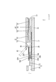
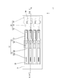
- FIG. 1 is a cross-sectional view showing a joint connector according to the first embodiment.
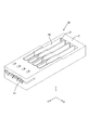
- FIG. 2 is a perspective view showing a lower housing.
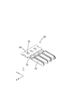
- FIG. 3 is a perspective view showing the upper cover.
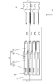
- FIG. 4 is a perspective view showing a bus bar.
- FIG. 5 is a perspective view showing a terminal in which the slide portion is held at the temporarily locked position with respect to the terminal body.
- FIG. 6 is a sectional view taken along line VI-VI in FIG.
- FIG. 7 is a cross-sectional view showing a state in which the slide portion is moved to the main locking position by the jig.
- FIG. 8 is a plan view showing a state in which the terminals are housed in the lower housing.
- FIG. 9 is a plan view showing a state in which the bus bar is inserted into the lower housing.
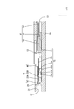
- FIG. 10 is a cross-sectional view taken along line XX in FIG.
- FIG. 11 is a sectional view taken along line XI-XI in FIG.
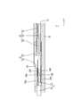
- FIG. 12 is a cross-sectional view showing a state in which an electric wire is inserted through the lower housing and terminals.
- FIG. 13 is a plan view showing a state in which the slide portion is moved to the main locking position.
- the present disclosure is a joint connector for connecting a plurality of electric wires, which are connected to a lower housing, an upper cover assembled to the lower housing, and front ends of the plurality of electric wires in an extending direction.
- the bus bar provided with a plurality of terminals and a bus bar connected to the plurality of terminals, the bus bar arranged in the lower housing has a plurality of tabs, and the plurality of terminals arranged in the lower housing.
- the terminal holding portion having the pressurizing portion and projecting downward from the upper cover engages with the terminal.
- the core wire and the terminal of the electric wire can be electrically connected without using a relatively large jig. it can.
- the manufacturing cost of the joint connector can be reduced.
- the manufacturing cost of the joint connector can be reduced.
- the terminal by inserting the bus bar into the cylinder portion, the terminal can be held in the lower housing by preventing it from coming off upward. This eliminates the need for a structure for retaining and holding the terminals, so that the structure of the joint connector can be simplified. As a result, the manufacturing cost of the joint connector can be reduced.
- the slide portion is a temporary locking position in which the pressurizing portion is separated from the pinching portion with respect to the pinching portion, and the pressurizing portion presses the sandwiching portion against the plurality of electric wires. It is possible to move between the locking position and the terminal holding portion, and it is preferable that the terminal holding portion is locked with the sliding portion at the main locking position with respect to the holding portion.
- the terminal holding portion provided on the upper cover is locked with the slide portion, so that it can be confirmed that the slide portion has moved to the main locking position.
- the lower housing has a rear wall located behind the plurality of terminals in the extension direction, and the rear wall has a plurality of rear walls through which the plurality of electric wires are inserted. It is preferable that the wire insertion hole is provided and the sandwiching portion is arranged in front of the wire insertion hole in the extending direction.
- the electric wire When the electric wire is inserted from the back of the electric wire insertion hole, the electric wire advances toward the holding portion located in front of the electric wire insertion hole. In this way, since the electric wire is guided to the sandwiching portion by the electric wire insertion hole, the manufacturing efficiency of the joint connector can be improved.
- the cross section of the electric wire insertion hole orthogonal to the extension direction is preferably smaller than the cross section of the slide portion orthogonal to the extension direction.
- the cross-sectional area of the electric wire insertion hole is smaller than the cross-sectional area of the slide portion, it is possible to prevent the slide portion from coming out of the lower housing through the electric wire insertion hole. As a result, the terminal in the state where the slide portion is held at the temporarily locked position can be held in the lower housing.
- Embodiment 1 of the present disclosure will be described with reference to FIGS. 1 to 13.
- the joint connector 10 electrically connects a plurality of electric wires 11.
- the direction indicated by the arrow Z will be on the top
- the direction indicated by the arrow Y will be the front
- the direction indicated by the arrow X will be on the left.
- a reference numeral may be added to only a part of the members, and the reference numerals of other members may be omitted.
- the joint connector 10 includes a plurality of terminals 12 connected to the front ends of the plurality of electric wires 11 in the extending direction (direction indicated by the arrow Y), and a plurality of terminals 12, respectively.
- the bus bar 50 is connected to the terminal 12, the lower housing 30 in which the plurality of terminals 12 and the bus bar 50 are housed, and the upper cover 60 attached to the upper part of the lower housing 30 at the rear.
- the plurality of electric wires 11 are arranged so as to extend in the front-rear direction (an example of the extending direction).
- the outer circumference of the core wire 13 of the electric wire 11 is surrounded by an insulating coating 14 made of an insulating synthetic resin.
- the core wire 13 according to the present embodiment is made of one metal wire.
- the core wire 13 may be a stranded wire obtained by twisting a plurality of fine metal wires.
- any metal such as copper, copper alloy, aluminum, and aluminum alloy can be appropriately selected as needed.
- the core wire 13 according to this embodiment is made of copper or a copper alloy.
- the lower housing 30 has a rectangular parallelepiped shape that is flat in the vertical direction.
- a material containing an insulating synthetic resin is formed by injection molding.
- a plurality of cavities 29 (four in the present embodiment) extending in the front-rear direction are formed in the lower housing 30 side by side in the left-right direction. The cavity 29 is opened upward so that the terminal 12 is inserted into the cavity 29 from above.
- the cavity 29 opens forward at the front end portion of the lower housing 30, and the bus bar 50 is a bus bar insertion hole 51 inserted into the cavity 29 from the front.
- the electric wire insertion hole 37 is provided at a position corresponding to the cavity 29 of the lower housing 30.
- the inner diameter of the electric wire insertion hole 37 is set to be the same as or slightly larger than the outer diameter of the insulating coating 14 of the electric wire 11.
- the upper portion of the lower housing 30 is covered by the upper cover 60 assembled from above.
- the lower housing 30 and the upper cover 60 are integrally assembled by a known lock structure.
- the upper cover 60 is formed by injection molding an insulating synthetic resin.
- the upper cover 60 has an upper wall 61 and two side walls 62 extending downward from both the left and right sides of the upper wall 61.
- terminal holding portions 63 (four in the plurality of embodiments) projecting downward extend in the front-rear direction.
- the terminal holding portion 63 includes a front terminal holding portion 63F located on the front side and a rear terminal holding portion 63R located on the rear portion of the front terminal holding portion 63F.
- the rear terminal holding portion 63R projects downward from the front terminal holding portion 63F.
- An arcuate groove 64 is formed on the lower surface of the rear terminal holding portion 63R.
- the inner shape of the groove 64 is the same as or slightly larger than the outer shape of the electric wire 11.
- the bus bar 50 is formed by pressing a metal plate material into a predetermined shape.
- the metal plate material any metal such as copper and copper alloy can be appropriately selected.
- the bus bar 50 has a plurality of (four in this embodiment) tabs 52 extending rearward, and a connecting portion 54 connecting the front end portions of the tabs 52 via a relay portion 53.
- the tab 52 has a flat plate shape in the left-right direction.
- the connecting portion 54 has a flat plate shape in the vertical direction.
- the relay portion 53 is formed so as to extend rearward from the connecting portion 54. The right edge of the connecting portion 54 is bent downward and is connected to the tab 52.
- each locking hole 56 accommodates a locking claw 35 projecting from the lower housing 30 toward the connecting portion 54. It has become. The front hole edge of the locking hole 56 comes into contact with the locking claw 35 from the front, so that the bus bar 50 is prevented from moving forward.
- the terminal 12 includes a metal terminal body 15 and a slide portion 16 that can slide relative to the terminal body 15.
- Terminal body 15 The terminal body 15 is formed into a predetermined shape by a known method such as pressing, cutting, casting, or the like.
- metal constituting the terminal body 15 any metal such as copper, copper alloy, aluminum, aluminum alloy, and stainless steel can be appropriately selected as needed.
- the terminal body 15 according to this embodiment is made of copper or a copper alloy.
- a plating layer may be formed on the surface of the terminal body 15.
- any metal such as tin, nickel, and silver can be appropriately selected as required.
- the terminal body 15 according to this embodiment is tin-plated.
- the terminal body 15 has a tubular portion 17 into which the tab 52 can be inserted, and an electric wire connecting portion 20 located behind the tubular portion 17 and connected to the electric wire 11.
- the electric wire connecting portion 20 includes an upper holding portion 18A and a lower holding portion 18B extending rearward.
- the tubular portion 17 has a square tubular shape extending in the front-rear direction.
- the front end of the tubular portion 17 is opened so that the tab 52 can be inserted.
- an elastic contact piece 19 that can be elastically deformed is arranged inside the tubular portion 17.
- the elastic contact piece 19 extends inward from the inner wall of the tubular portion 17.
- the tab 52 inserted into the tubular portion 17 presses the elastic contact piece 19 to elastically deform it.
- the tab 52 is sandwiched between the inner wall of the tubular portion 17 and the elastic contact piece 19 due to the elastic force of the elastically deformed elastic contact piece 19. As a result, the tab 52 and the terminal 12 are electrically connected.
- a square tubular electric wire connecting portion 20 is provided behind the tubular portion 17.
- An upper holding portion 18A (an example of a holding portion) is provided at the rear end of the upper wall of the electric wire connecting portion 20 so as to extend rearward
- a lower holding portion is provided at the rear end of the lower wall of the electric wire connecting portion 20.
- 18B (an example of a holding portion) is provided so as to extend rearward.
- the upper holding portion 18A and the lower holding portion 18B have an elongated shape extending back and forth.
- the upper holding portion 18A and the lower holding portion 18B are formed to have substantially the same length dimension in the front-rear direction.
- an upper holding protrusion 23A protruding downward is provided at a position in front of the rear end portion.
- a lower holding protrusion 23B protruding upward is provided.
- the lower holding protrusion 23B and the upper holding protrusion 23A are provided at positions shifted in the front-rear direction.
- the core wire 13 and the terminal body 15 are electrically connected by contacting the metal surface with the upper holding portion 18A and the lower holding portion 18B.
- the slide portion 16 has a square tubular shape extending in the front-rear direction.
- the slide portion 16 is formed by a known method such as cutting, casting, or pressing, if necessary.
- any metal such as copper, copper alloy, aluminum, aluminum alloy, and stainless steel can be appropriately selected as needed.
- the slide portion 16 according to the present embodiment is not particularly limited, but is made of stainless steel.
- a plating layer may be formed on the surface of the slide portion 16.
- any metal such as tin, nickel, and silver can be appropriately selected as required.
- the cross-sectional shape of the slide portion 16 is the same as or slightly larger than the cross-sectional shape of the region of the terminal body 15 where the upper holding portion 18A and the lower holding portion 18B are provided. As a result, the slide portion 16 is arranged outside the region of the terminal body 15 where the upper holding portion 18A and the lower holding portion 18B are provided.
- the cross-sectional area of the electric wire insertion hole 37 orthogonal to the front-rear direction is smaller than the cross-section of the slide portion 16 orthogonal to the front-rear direction. As a result, the slide portion 16 cannot pass through the electric wire insertion hole 37 in the front-rear direction.
- an upper pressurizing portion 25A (an example of the pressurizing portion) projecting downward is provided on the lower surface of the upper wall of the slide portion 16.
- a lower pressurizing portion 25B (an example of the pressurizing portion) projecting upward is provided.
- a temporary locking receiving portion 26 is opened on the side wall of the slide portion 16 at a position closer to the front end portion in the front-rear direction. Further, on the side wall of the slide portion 16, the main locking receiving portion 27 is opened at a position behind the temporary locking receiving portion 26.
- the temporary locking receiving portion 26 and the main locking receiving portion 27 can be elastically locked with the locking projection 28 provided on the side wall of the terminal body 15.
- the state in which the locking projection 28 of the terminal body 15 and the temporary locking receiving portion 26 of the slide portion 16 are locked is a state in which the sliding portion 16 is held at the temporary locking position with respect to the terminal main body 15. (See FIG. 8).
- the upper pressurizing portion 25A and the lower pressurizing portion 25B of the slide portion 16 are separated rearward from the rear end edges of the upper holding portion 18A and the lower holding portion 18B of the terminal body 15. Further, in this state, the distance between the upper holding portion 18A and the lower holding portion 18B is set to be larger than the diameter of the core wire 13.
- the slide portion 16 is locked at the main locking position with respect to the terminal main body 15. There is. As shown in FIG. 1, in this state, the upper pressurizing portion 25A of the slide portion 16 is in contact with the upper holding portion 18A from above the upper holding portion 18A. Further, the lower pressurizing portion 25B of the slide portion 16 is in contact with the lower holding portion 18B from below the lower holding portion 18B.
- the slide portion 16 is fitted into the region of the terminal body 15 where the upper holding portion 18A and the lower holding portion 18B are provided, and is fitted into the above-mentioned temporary locking position and the main locking. It can be slid to and from the position.
- the upper holding portion 18A is pressed by the upper pressing portion 25A from above to press the upper holding portion 18A. Is designed to deform downward. Further, the lower pressing portion 25B presses the lower holding portion 18B from below, so that the lower holding portion 18B is deformed upward. As a result, the core wire 13 is arranged in the space between the upper holding portion 18A and the lower holding portion 18B in a state of being extended in the front-rear direction (extending direction), and the slide portion 16 is arranged with respect to the terminal body 15.
- the core wire 13 is sandwiched from the vertical direction by the elastically deformed upper holding portion 18A and the lower holding portion 18B. That is, the upper holding portion 18A comes into contact with the core wire 13 from above by being pressed downward by the upper pressing portion 25A, and the lower holding portion 18B is pressed upward by the lower pressing portion 25B to bring the core wire 13 into contact. It comes in contact with the cable from below.
- the upper holding protrusion 23A of the upper holding portion 18A presses the core wire 13 from above, and the lower side.
- the lower holding protrusion 23B of the holding portion 18B presses the core wire 13 from below.
- the core wire 13 is pressed from above by the upper holding protrusion 23A and is pressed from below by the lower holding protrusion 23B arranged at a position deviated from the upper holding protrusion 23A in the front-rear direction. Therefore, it is held in a bent state in the vertical direction (an example of a direction intersecting the extending direction).
- the core wire 13 and the terminal 12 are also electrically connected by the upper holding protrusion 23A and the lower holding protrusion 23B.
- a jig contact portion 46 projecting upward from the upper wall is provided at the front end portion of the slide portion 16.
- the jig 45 comes into contact with the jig contact portion 46 from the rear, and the slide portion 16 is pushed forward by the jig 45, so that the slide portion 16 can move forward.
- the jig 45 is relatively small in size as compared with a mold and equipment for operating the mold. Therefore, the increase in cost caused by the jig 45 is suppressed.
- a pair of invitation portions 47 projecting inward of the slide portion 16 are provided on the left and right side walls at a position near the rear end portion of the slide portion 16.
- the invitation portion 47 is formed narrower from the rear to the front.
- the terminal body 15 and the slide portion 16 are formed by a known method.
- the slide portion 16 is assembled from the rear to the terminal body 15.
- the front end edge of the slide portion 16 comes into contact with the locking projection 28 of the terminal body 15 from the rear, and the side wall of the slide portion 16 is expanded and deformed.
- the slide portion 16 is further pushed forward, the side wall of the slide portion 16 is restored and deformed, and the temporary locking receiving portion 26 of the slide portion 16 is locked to the locking projection 28 of the terminal body 15.
- the slide portion 16 is held at the temporarily locked position with respect to the terminal body 15 (see FIG. 5).
- the terminal 12 is obtained.
- the lower housing 30 and the upper cover 60 are formed by injection molding the synthetic resin.
- the terminal 12 in which the slide portion 16 is temporarily locked with respect to the terminal body 15 is inserted into the cavity 29 of the lower housing 30 from above.
- the rear end of the slide portion 16 is located in front of the rear wall 31 of the lower housing 30, and the front end of the tubular portion 17 of the terminal body 15 is located behind the front wall of the lower housing 30.
- the terminal 12 is held in the cavity 29 in a state of being positioned in the front-rear direction.
- the bus bar 50 is inserted into the bus bar insertion hole 51 of the lower housing 30 from the front.
- the bus bar 50 is held in the lower housing 30 in a retaining state (see FIG. 10).
- the tab 52 of the bus bar 50 is inserted into the tubular portion 17 of the terminal 12.
- the tab 52 and the terminal 12 are electrically connected.
- the plurality of terminals 12 are electrically connected via the bus bar 50.
- the core wire 13 of the electric wire 11 is exposed by peeling the insulating coating 14 by a known method. As shown in FIG. 12, the front end portion of the core wire 13 is inserted from the rear into the electric wire insertion hole 37 provided in the rear wall 31.
- the front end portion of the core wire 13 is introduced from the rear end portion of the slide portion 16 into the inside of the slide portion 16.
- the core wire 13 is guided to the slide portion 16 by coming into contact with the invitation portion 47 of the slide portion 16. Further, when the electric wire 11 is pushed forward, the front end portion of the core wire 13 enters the inside of the terminal body 15 and reaches the space between the upper holding portion 18A and the lower holding portion 18B.
- the distance between the upper holding portion 18A and the lower holding portion 18B is the outer diameter dimension of the core wire 13. Is set larger than.
- the jig 45 is brought into contact with the jig contact portion 46 from the rear, and the slide portion 16 is slid forward.
- the slide portion 16 is moved forward relative to the terminal body 15.
- the locking projection 28 of the terminal body 15 and the temporary locking receiving portion 26 of the slide portion 16 are disengaged, and the side wall of the slide portion 16 rides on the locking projection 28 to expand and deform.
- the upper pressurizing portion 25A of the slide portion 16 abuts on the upper holding portion 18A of the terminal body 15 from above and presses downward.
- the lower pressurizing portion 25B of the slide portion 16 abuts on the lower holding portion 18B of the terminal body 15 from below and presses it upward.
- the core wire 13 is sandwiched between the upper sandwiching portion 18A and the lower sandwiching portion 18B from above and below (see FIG. 11).
- the core wire 13 is sandwiched between the lower surface of the upper holding portion 18A and the upper surface of the lower holding portion 18B, so that the oxide film formed on the surface of the core wire 13 is peeled off, and the core wire 13 is removed.
- the constituent metal surface is exposed.
- the electric wire 11 and the terminal 12 are electrically connected by contacting the metal surface with the upper holding portion 18A and the lower holding portion 18B.
- the plurality of electric wires 11 are electrically connected via the terminal 12 and the bus bar 50 (see FIG. 13).
- the core wire 13 In a state where the core wire 13 is sandwiched between the upper holding portion 18A and the lower holding portion 18B from above and below, the core wire 13 has the upper holding protrusion 23A of the upper holding portion 18A and the lower holding protrusion portion 18B of the lower holding portion 18B.
- the cable By being sandwiched between the 23B, the cable is held in a state of being extended in the front-rear direction and in a state of being bent in the vertical direction.
- the core wire 13 can be firmly held, so that when a tensile force acts on the electric wire 11, the holding force between the electric wire 11 and the terminal 12 can be increased.
- the upper cover 60 is assembled to the lower housing 30 from above the lower housing 30. With the lower housing 30 and the upper cover 60 assembled, the front end portion of the front terminal holding portion 63F of the upper cover 60 is located behind the jig contact portion 46 of the slide portion 16. When the front end portion of the front terminal holding portion 63F comes into contact with the slide portion 16 from the rear, the movement of the slide portion 16 to the rear is suppressed.
- the front terminal holding portion 63F is locked so as to cover the upper part of the slide portion 16.
- the terminal 12 is held upward in the cavity 29 in a retaining state.
- the rear terminal holding portion 63R is located behind the slide portion 16.
- the terminal 12 is held in the cavity 29 in a rearward retaining state. This completes the joint connector 10.
- the joint connector 10 is a joint connector 10 for connecting a plurality of electric wires 11, the lower housing 30, the upper cover 60 assembled to the lower housing 30, and the front of the plurality of electric wires 11 in the extending direction.
- the bus bar 50 arranged in the lower housing 30 includes a plurality of terminals 12 connected to each end and a bus bar 50 connected to the plurality of terminals 12, and the bus bar 50 arranged in the lower housing 30 has a plurality of tabs 52 and the lower housing 30.
- Each of the plurality of terminals 12 arranged in the above includes a tubular portion 17 into which each of the plurality of tabs 52 is inserted, an upper holding portion 18A extending along the extending direction and sandwiching one of the plurality of electric wires 11. It has a lower holding portion 18B, a slide portion 16 that is arranged outside the upper holding portion 18A and the lower holding portion 18B and is movable along an extension direction, and the slide portion 16 has an upper holding portion 18A.
- the upper pressing portion 25A and the lower pressing portion pressurize the upper holding portion 18A and the lower holding portion 18B toward the electric wire 11.
- the terminal holding portion 63 having 25B and protruding downward from the upper cover 60 engages with the terminal 12.
- the core wire 13 and the terminal 12 of the electric wire 11 can be separated from each other without using a relatively large jig. Can be connected electrically. As a result, the manufacturing cost of the joint connector 10 can be reduced.
- the manufacturing cost of the joint connector 10 can be reduced.
- the terminal 12 can be held in the lower housing 30 by preventing it from coming off upward. This eliminates the need for a structure for retaining and holding the terminal 12, so that the structure of the joint connector 10 can be simplified. As a result, the manufacturing cost of the joint connector 10 can be reduced.
- the slide portion 16 is temporarily locked with respect to the upper holding portion 18A and the lower holding portion 18B so that the upper pressing portion 25A and the lower pressing portion 25B are separated from the upper holding portion 18A and the lower holding portion 18B. It is possible to move between the position and the main locking position where the upper pressurizing portion 25A and the lower pressurizing portion 25B press the upper holding portion 18A and the lower holding portion 18B against the plurality of electric wires 11.
- the holding portion 63 engages with the slide portion 16 at the main locking position with respect to the upper holding portion 18A and the lower holding portion 18B.
- the front terminal holding portion 63F is locked so as to cover the upper part of the slide portion 16.
- the terminal 12 is held upward in the cavity 29 in a retaining state.
- the rear terminal holding portion 63R is located behind the slide portion 16.
- the terminal 12 is held in the cavity 29 in a rearward retaining state.
- the terminal holding portion 63 front terminal holding portion 63F and rear terminal holding portion 63R
- the slide portion 16 has moved to the main locking position.
- the lower housing 30 has a rear wall 31 located behind the plurality of terminals 12 in the extending direction, and the rear wall 31 is penetrated in the extending direction through which the plurality of electric wires 11 are inserted.
- a plurality of electric wire insertion holes 37 are provided, and an upper holding portion 18A and a lower holding portion 18B are arranged in front of the electric wire insertion holes 37.
- the electric wire 11 When the electric wire 11 is inserted from the rear of the electric wire insertion hole 37, the electric wire 11 enters between the upper holding portion 18A and the lower holding portion 18B located in front of the electric wire insertion hole 37. In this way, since the electric wire 11 is guided between the upper sandwiching portion 18A and the lower sandwiching portion 18B by the electric wire insertion hole 37, the manufacturing efficiency of the joint connector 10 can be improved.
- the cross-sectional area of the electric wire insertion hole 37 orthogonal to the front-rear direction is smaller than the cross-section of the slide portion 16 orthogonal to the front-rear direction.
- the cross-sectional area of the electric wire insertion hole 37 is smaller than the cross-sectional area of the slide portion 16, it is possible to prevent the slide portion 16 from coming out of the lower housing 30 through the electric wire insertion hole 37. As a result, the terminal 12 in which the slide portion 16 is held in the temporarily locked position can be held in the lower housing 30.
- the number of terminals 12 arranged in the lower housing 30 may be two, three, or five or more.
- the upper cover 60 and the lower housing 30 may be integrated by a hinge or the like.
- the terminal 12 may have one or more holding portions.
Landscapes
- Connector Housings Or Holding Contact Members (AREA)
- Manufacturing Of Electrical Connectors (AREA)
Priority Applications (2)
| Application Number | Priority Date | Filing Date | Title |
|---|---|---|---|
| CN202080021947.4A CN113574741B (zh) | 2019-03-28 | 2020-03-24 | 接头连接器 |
| US17/598,477 US11942737B2 (en) | 2019-03-28 | 2020-03-24 | Joint connector |
Applications Claiming Priority (2)
| Application Number | Priority Date | Filing Date | Title |
|---|---|---|---|
| JP2019-063732 | 2019-03-28 | ||
| JP2019063732A JP7088109B2 (ja) | 2019-03-28 | 2019-03-28 | ジョイントコネクタ |
Publications (1)
| Publication Number | Publication Date |
|---|---|
| WO2020196480A1 true WO2020196480A1 (ja) | 2020-10-01 |
Family
ID=72610988
Family Applications (1)
| Application Number | Title | Priority Date | Filing Date |
|---|---|---|---|
| PCT/JP2020/012899 Ceased WO2020196480A1 (ja) | 2019-03-28 | 2020-03-24 | ジョイントコネクタ |
Country Status (4)
| Country | Link |
|---|---|
| US (1) | US11942737B2 (enExample) |
| JP (1) | JP7088109B2 (enExample) |
| CN (1) | CN113574741B (enExample) |
| WO (1) | WO2020196480A1 (enExample) |
Cited By (1)
| Publication number | Priority date | Publication date | Assignee | Title |
|---|---|---|---|---|
| CN119199202A (zh) * | 2024-11-29 | 2024-12-27 | 海盐德创电子有限公司 | 一种电能表测试工装 |
Families Citing this family (4)
| Publication number | Priority date | Publication date | Assignee | Title |
|---|---|---|---|---|
| JP7088110B2 (ja) * | 2019-03-28 | 2022-06-21 | 株式会社オートネットワーク技術研究所 | ジョイントコネクタ |
| JP2021190286A (ja) * | 2020-05-29 | 2021-12-13 | 株式会社オートネットワーク技術研究所 | 端子、および端子付き電線 |
| JP7400640B2 (ja) * | 2020-06-25 | 2023-12-19 | 株式会社オートネットワーク技術研究所 | コネクタ |
| KR102510449B1 (ko) * | 2020-10-29 | 2023-03-16 | 주식회사 유라코퍼레이션 | 인터락 조인트 어셈블리 및 정션블록 |
Citations (10)
| Publication number | Priority date | Publication date | Assignee | Title |
|---|---|---|---|---|
| JP2001006788A (ja) * | 1999-06-03 | 2001-01-12 | Whitaker Corp:The | 電気コネクタ及び電気コネクタ用ケース |
| JP2005129447A (ja) * | 2003-10-27 | 2005-05-19 | Smk Corp | 電線接続用プラグ |
| JP2013247057A (ja) * | 2012-05-29 | 2013-12-09 | Sumitomo Wiring Syst Ltd | コネクタ |
| JP2019096426A (ja) * | 2017-11-21 | 2019-06-20 | 矢崎総業株式会社 | ジョイント端子 |
| WO2019159714A1 (ja) * | 2018-02-15 | 2019-08-22 | 株式会社オートネットワーク技術研究所 | 端子付き電線 |
| WO2019159730A1 (ja) * | 2018-02-15 | 2019-08-22 | 株式会社オートネットワーク技術研究所 | 端子 |
| WO2019159746A1 (ja) * | 2018-02-15 | 2019-08-22 | 株式会社オートネットワーク技術研究所 | 端子、及び端子付き電線 |
| JP2019145208A (ja) * | 2018-02-15 | 2019-08-29 | 株式会社オートネットワーク技術研究所 | 端子、及びコネクタ |
| WO2019225462A1 (ja) * | 2018-05-25 | 2019-11-28 | 株式会社オートネットワーク技術研究所 | 端子 |
| WO2019235389A1 (ja) * | 2018-06-05 | 2019-12-12 | 株式会社オートネットワーク技術研究所 | ジョイントコネクタ |
Family Cites Families (14)
| Publication number | Priority date | Publication date | Assignee | Title |
|---|---|---|---|---|
| US4597622A (en) * | 1985-03-25 | 1986-07-01 | Qa Technology Company | Electrical connector for electrical circuit test probe and connector |
| JP2861661B2 (ja) * | 1992-08-25 | 1999-02-24 | 住友電装株式会社 | ジョイントコネクタ |
| JP3269920B2 (ja) * | 1994-07-28 | 2002-04-02 | 三菱電機株式会社 | コネクタ |
| JP3681881B2 (ja) * | 1998-01-29 | 2005-08-10 | 菱星電装株式会社 | ジョイントコネクタ |
| JP3731393B2 (ja) * | 1999-07-27 | 2006-01-05 | 住友電装株式会社 | ジョイントコネクタ |
| JP3551103B2 (ja) * | 1999-10-22 | 2004-08-04 | 住友電装株式会社 | ジョイント端子およびジョイントコネクタ |
| JP2004014220A (ja) * | 2002-06-05 | 2004-01-15 | Sumitomo Wiring Syst Ltd | ジョイントコネクタ |
| JP2008098118A (ja) * | 2006-10-16 | 2008-04-24 | Auto Network Gijutsu Kenkyusho:Kk | 分岐コネクタ |
| JP4813391B2 (ja) * | 2007-02-05 | 2011-11-09 | 株式会社オートネットワーク技術研究所 | 分岐コネクタ |
| CN101630790A (zh) * | 2008-07-08 | 2010-01-20 | 住友电装株式会社 | 连接器、设置有该连接器的线束以及连接方法 |
| JP5642504B2 (ja) | 2010-10-29 | 2014-12-17 | 矢崎総業株式会社 | ジョイントコネクタ |
| WO2014188933A1 (ja) * | 2013-05-20 | 2014-11-27 | 矢崎総業株式会社 | コネクタ |
| JP6018975B2 (ja) * | 2013-05-28 | 2016-11-02 | 矢崎総業株式会社 | ジョイントコネクタ |
| JP6254893B2 (ja) * | 2014-04-17 | 2017-12-27 | 矢崎総業株式会社 | コネクタ |
-
2019
- 2019-03-28 JP JP2019063732A patent/JP7088109B2/ja active Active
-
2020
- 2020-03-24 WO PCT/JP2020/012899 patent/WO2020196480A1/ja not_active Ceased
- 2020-03-24 CN CN202080021947.4A patent/CN113574741B/zh active Active
- 2020-03-24 US US17/598,477 patent/US11942737B2/en active Active
Patent Citations (10)
| Publication number | Priority date | Publication date | Assignee | Title |
|---|---|---|---|---|
| JP2001006788A (ja) * | 1999-06-03 | 2001-01-12 | Whitaker Corp:The | 電気コネクタ及び電気コネクタ用ケース |
| JP2005129447A (ja) * | 2003-10-27 | 2005-05-19 | Smk Corp | 電線接続用プラグ |
| JP2013247057A (ja) * | 2012-05-29 | 2013-12-09 | Sumitomo Wiring Syst Ltd | コネクタ |
| JP2019096426A (ja) * | 2017-11-21 | 2019-06-20 | 矢崎総業株式会社 | ジョイント端子 |
| WO2019159714A1 (ja) * | 2018-02-15 | 2019-08-22 | 株式会社オートネットワーク技術研究所 | 端子付き電線 |
| WO2019159730A1 (ja) * | 2018-02-15 | 2019-08-22 | 株式会社オートネットワーク技術研究所 | 端子 |
| WO2019159746A1 (ja) * | 2018-02-15 | 2019-08-22 | 株式会社オートネットワーク技術研究所 | 端子、及び端子付き電線 |
| JP2019145208A (ja) * | 2018-02-15 | 2019-08-29 | 株式会社オートネットワーク技術研究所 | 端子、及びコネクタ |
| WO2019225462A1 (ja) * | 2018-05-25 | 2019-11-28 | 株式会社オートネットワーク技術研究所 | 端子 |
| WO2019235389A1 (ja) * | 2018-06-05 | 2019-12-12 | 株式会社オートネットワーク技術研究所 | ジョイントコネクタ |
Cited By (1)
| Publication number | Priority date | Publication date | Assignee | Title |
|---|---|---|---|---|
| CN119199202A (zh) * | 2024-11-29 | 2024-12-27 | 海盐德创电子有限公司 | 一种电能表测试工装 |
Also Published As
| Publication number | Publication date |
|---|---|
| CN113574741A (zh) | 2021-10-29 |
| JP7088109B2 (ja) | 2022-06-21 |
| US11942737B2 (en) | 2024-03-26 |
| US20220190534A1 (en) | 2022-06-16 |
| CN113574741B (zh) | 2023-10-20 |
| JP2020166947A (ja) | 2020-10-08 |
Similar Documents
| Publication | Publication Date | Title |
|---|---|---|
| JP7088109B2 (ja) | ジョイントコネクタ | |
| JP6713009B2 (ja) | 端子、及びコネクタ | |
| US11228152B2 (en) | Joint connector | |
| JP6664434B2 (ja) | 端子 | |
| US11165172B2 (en) | Terminal and wire with terminal | |
| CN102823065A (zh) | 用于电连接器的缆线理线器 | |
| WO2020196478A1 (ja) | ジョイントコネクタ | |
| JPWO2020209348A1 (ja) | コネクタ | |
| JP7158349B2 (ja) | 端子、および端子付き電線 | |
| JP7168524B2 (ja) | 端子 | |
| CN114008868A (zh) | 端子及带端子的电线 | |
| JP7140034B2 (ja) | ジョイントコネクタ | |
| JP7177995B2 (ja) | ジョイントコネクタ | |
| US11799216B2 (en) | Terminal and wire with terminal | |
| JP7255449B2 (ja) | ジョイントコネクタ | |
| WO2021261210A1 (ja) | コネクタ | |
| JP7404949B2 (ja) | コネクタ、及びコネクタの製造方法 | |
| WO2021241294A1 (ja) | 端子、および端子付き電線 | |
| WO2020209178A1 (ja) | 端子、および端子付き電線 |
Legal Events
| Date | Code | Title | Description |
|---|---|---|---|
| 121 | Ep: the epo has been informed by wipo that ep was designated in this application |
Ref document number: 20777042 Country of ref document: EP Kind code of ref document: A1 |
|
| NENP | Non-entry into the national phase |
Ref country code: DE |
|
| 122 | Ep: pct application non-entry in european phase |
Ref document number: 20777042 Country of ref document: EP Kind code of ref document: A1 |