WO2020189356A1 - 車両用ディスクブレーキのキャリパボディ - Google Patents
車両用ディスクブレーキのキャリパボディ Download PDFInfo
- Publication number
- WO2020189356A1 WO2020189356A1 PCT/JP2020/009902 JP2020009902W WO2020189356A1 WO 2020189356 A1 WO2020189356 A1 WO 2020189356A1 JP 2020009902 W JP2020009902 W JP 2020009902W WO 2020189356 A1 WO2020189356 A1 WO 2020189356A1
- Authority
- WO
- WIPO (PCT)
- Prior art keywords
- caliper body
- disc
- casting
- caliper
- vehicle
- Prior art date
- Legal status (The legal status is an assumption and is not a legal conclusion. Google has not performed a legal analysis and makes no representation as to the accuracy of the status listed.)
- Ceased
Links
Images





Classifications
-
- B—PERFORMING OPERATIONS; TRANSPORTING
- B22—CASTING; POWDER METALLURGY
- B22C—FOUNDRY MOULDING
- B22C9/00—Moulds or cores; Moulding processes
-
- B—PERFORMING OPERATIONS; TRANSPORTING
- B22—CASTING; POWDER METALLURGY
- B22C—FOUNDRY MOULDING
- B22C9/00—Moulds or cores; Moulding processes
- B22C9/08—Features with respect to supply of molten metal, e.g. ingates, circular gates, skim gates
-
- B—PERFORMING OPERATIONS; TRANSPORTING
- B22—CASTING; POWDER METALLURGY
- B22C—FOUNDRY MOULDING
- B22C9/00—Moulds or cores; Moulding processes
- B22C9/22—Moulds for peculiarly-shaped castings
-
- B—PERFORMING OPERATIONS; TRANSPORTING
- B22—CASTING; POWDER METALLURGY
- B22D—CASTING OF METALS; CASTING OF OTHER SUBSTANCES BY THE SAME PROCESSES OR DEVICES
- B22D31/00—Cutting-off surplus material, e.g. gates; Cleaning and working on castings
-
- F—MECHANICAL ENGINEERING; LIGHTING; HEATING; WEAPONS; BLASTING
- F16—ENGINEERING ELEMENTS AND UNITS; GENERAL MEASURES FOR PRODUCING AND MAINTAINING EFFECTIVE FUNCTIONING OF MACHINES OR INSTALLATIONS; THERMAL INSULATION IN GENERAL
- F16D—COUPLINGS FOR TRANSMITTING ROTATION; CLUTCHES; BRAKES
- F16D55/00—Brakes with substantially-radial braking surfaces pressed together in axial direction, e.g. disc brakes
- F16D55/02—Brakes with substantially-radial braking surfaces pressed together in axial direction, e.g. disc brakes with axially-movable discs or pads pressed against axially-located rotating members
- F16D55/22—Brakes with substantially-radial braking surfaces pressed together in axial direction, e.g. disc brakes with axially-movable discs or pads pressed against axially-located rotating members by clamping an axially-located rotating disc between movable braking members, e.g. movable brake discs or brake pads
- F16D55/224—Brakes with substantially-radial braking surfaces pressed together in axial direction, e.g. disc brakes with axially-movable discs or pads pressed against axially-located rotating members by clamping an axially-located rotating disc between movable braking members, e.g. movable brake discs or brake pads with a common actuating member for the braking members
- F16D55/225—Brakes with substantially-radial braking surfaces pressed together in axial direction, e.g. disc brakes with axially-movable discs or pads pressed against axially-located rotating members by clamping an axially-located rotating disc between movable braking members, e.g. movable brake discs or brake pads with a common actuating member for the braking members the braking members being brake pads
- F16D55/226—Brakes with substantially-radial braking surfaces pressed together in axial direction, e.g. disc brakes with axially-movable discs or pads pressed against axially-located rotating members by clamping an axially-located rotating disc between movable braking members, e.g. movable brake discs or brake pads with a common actuating member for the braking members the braking members being brake pads in which the common actuating member is moved axially, e.g. floating caliper disc brakes
-
- F—MECHANICAL ENGINEERING; LIGHTING; HEATING; WEAPONS; BLASTING
- F16—ENGINEERING ELEMENTS AND UNITS; GENERAL MEASURES FOR PRODUCING AND MAINTAINING EFFECTIVE FUNCTIONING OF MACHINES OR INSTALLATIONS; THERMAL INSULATION IN GENERAL
- F16D—COUPLINGS FOR TRANSMITTING ROTATION; CLUTCHES; BRAKES
- F16D65/00—Parts or details
- F16D65/14—Actuating mechanisms for brakes; Means for initiating operation at a predetermined position
- F16D65/16—Actuating mechanisms for brakes; Means for initiating operation at a predetermined position arranged in or on the brake
- F16D65/18—Actuating mechanisms for brakes; Means for initiating operation at a predetermined position arranged in or on the brake adapted for drawing members together, e.g. for disc brakes
- F16D65/183—Actuating mechanisms for brakes; Means for initiating operation at a predetermined position arranged in or on the brake adapted for drawing members together, e.g. for disc brakes with force-transmitting members arranged side by side acting on a spot type force-applying member
-
- B—PERFORMING OPERATIONS; TRANSPORTING
- B62—LAND VEHICLES FOR TRAVELLING OTHERWISE THAN ON RAILS
- B62L—BRAKES SPECIALLY ADAPTED FOR CYCLES
- B62L1/00—Brakes; Arrangements thereof
- B62L1/005—Brakes; Arrangements thereof constructional features of brake elements, e.g. fastening of brake blocks in their holders
-
- F—MECHANICAL ENGINEERING; LIGHTING; HEATING; WEAPONS; BLASTING
- F16—ENGINEERING ELEMENTS AND UNITS; GENERAL MEASURES FOR PRODUCING AND MAINTAINING EFFECTIVE FUNCTIONING OF MACHINES OR INSTALLATIONS; THERMAL INSULATION IN GENERAL
- F16D—COUPLINGS FOR TRANSMITTING ROTATION; CLUTCHES; BRAKES
- F16D2121/00—Type of actuator operation force
- F16D2121/02—Fluid pressure
- F16D2121/04—Fluid pressure acting on a piston-type actuator, e.g. for liquid pressure
Definitions
- the present invention relates to a caliper body of a vehicle disc brake.
- a caliper body of a disc brake for a vehicle there is a caliper body formed by connecting an action portion having a cylinder hole and a reaction portion having a reaction force claw at a bridge portion (see, for example, Patent Document 1). ..
- an object of the present invention is to provide a caliper body for a disc brake for a vehicle, which can reduce the weight and, in the case of being formed by casting, can also improve the hot water circulation.
- the caliper body of the vehicle disc brake of the present invention is arranged on the side portion of the disc rotor, and has a working portion provided with a cylinder hole and a bridge portion arranged straddling the disc rotor.
- the caliper body of the vehicle disc brake provided is characterized in that the bridge portion is formed with a lightening portion that gradually becomes thinner toward the central portion in the disc axial direction.
- the lightening portion is formed of an inclined surface that gradually becomes thinner toward the central portion in the disc axial direction.
- the caliper body is formed by connecting the action portion and the reaction portion provided with a plurality of reaction force claws at the bridge portion, and the reaction portion is formed in the intermediate portion of the adjacent reaction force claws. , It is preferable that the reaction force claw side lightening portion that becomes concave toward the outer peripheral side of the disc is formed.
- the caliper body is formed by casting, and the bridge portion is provided with a sprue trace formed by cutting the sprue after casting the caliper body on the outer surface, and the lightening portion is provided on the inner surface corresponding to the sprue trace. It is preferable that it is formed.
- the weight of the caliper body can be reduced by forming a lightening portion in the bridge portion that gradually becomes thinner toward the central portion in the disc axial direction.
- the lightening portion can be easily formed by forming the lightening portion on an inclined surface that gradually becomes thinner toward the central portion in the disc axial direction.
- the reaction force claw that becomes concave toward the outer peripheral side of the disc in the middle portion of the adjacent reaction force claws. Since the side lightening portion is formed, the caliper body can be further reduced in weight.
- the caliper body is formed by casting, and has a sprue trace formed by cutting the sprue after casting the caliper body on the outer surface of the bridge portion, and a lightening portion is formed on the inner surface of the bridge portion corresponding to the sprue trace.
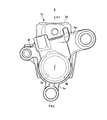
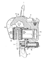
- FIG. 2 is a sectional view taken along line II of FIG. It is a front view of the caliper body which shows an example of one embodiment of this invention. It is also a rear view of the caliper body. It is also a front view of a vehicle disc brake. It is a VV cross-sectional view of FIG. It is a partial cross-sectional plan view of the disc brake for a vehicle which shows one embodiment of this invention.
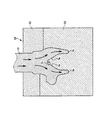
- FIG. 6 is a sectional view taken along line VII-VII of FIG. It is explanatory drawing which shows the casting state of a caliper body.
- FIG. 8 is a cross-sectional view taken along the line IX-IX of FIG.
- FIG. 1 to 7 are views showing an example of a caliper body of the disc brake for a vehicle of the present invention
- arrow A indicates a rotation direction of a disc rotor that rotates integrally with a wheel when the vehicle moves forward, and the disc described below.
- the turn-out side and the disc turn-in side are when the vehicle is moving forward.
- the vehicle disc brake 1 is movable in the disc axial direction via a disc rotor 2 that rotates integrally with the rear wheels, a caliper bracket 3 fixed to the vehicle body, and slide pins 4 and 4 on the caliper bracket 3. It includes a supported caliper body 5 and a pair of friction pads 6 and 6 arranged so as to face each other with the disc rotor 2 sandwiched between the acting portion 5a and the reaction portion 5b of the caliper body 5.
- the caliper bracket 3 includes a caliper support arm 3a on the exit side and a caliper support arm 3b on the enter side, and a friction pad 6 is provided between the caliper support arm 3a on the exit side and the caliper support arm 3b on the enter side.
- the accommodating portion 3c of 6 is formed.
- a U-shaped torque receiving portion 3d is provided on the side surface of the feeding side caliper supporting arm 3a on the accommodating portion side, and the tip end side of the feeding side caliper supporting arm 3a straddles the outer circumference of the disc rotor 2.
- the caliper support arm 3e is projected in the direction of the disc axis, and the caliper support arm 3e is formed with a bag-shaped slide pin insertion hole 3f.
- the caliper body 5 is formed by casting, and the action portion 5a and the reaction portion 5b arranged on both side portions of the disc rotor 2 are connected by a bridge portion 5c straddling the outer circumference of the disc rotor 2 to act.
- the pair of friction pads 6 and 6 are arranged between the portion 5a and the reaction portion 5b so as to face each other with the disc rotor 2 interposed therebetween.
- the working portion 5a is formed by opening a bottomed cylinder hole 5d on the disc rotor side, and a piston 7 is movably inserted inside the working portion 5a, and a hydraulic pressure is formed between the bottom side of the cylinder hole 5d and the piston 7. Room 8 is defined. Further, the vehicle body mounting arms 5e and 5e are projected from the acting portion 5a toward the disc feeding side and the inside in the disc radial direction, and the guide arms 5f and 5f are provided on the disc turning side of the acting portion 5a and the reaction portion 5b. It is projected.
- the bridge portion 5c includes a sprue trace 5g formed by cutting the sprue 21 after casting the caliper body 5 on the outer surface, and gradually thins the inner surface 5h corresponding to the sprue trace 5g toward the central portion C1 in the disk axial direction.
- a lightening portion 5j formed by the inclined surfaces 5i and 5i is provided.
- the reaction portion 5b is provided with a pair of reaction force claws 5k and 5k, and an inverted U-shaped opening is opened between the reaction force claws 5k and 5k at a position corresponding to the cylinder hole 5d toward the center of the disk. A portion of 5 m is formed. Further, a reaction force claw side lightening portion 5n that becomes concave toward the outer peripheral side of the disc is formed in the middle portion of the opening 5m, and the reaction force claw side lightening portion 5n is substantially directed toward the outer peripheral side of the disc. It is provided with a pair of reaction force claw-side inclined surfaces 5p and 5p that are concave in a triangular shape.
- Each friction pad 6 is configured by joining a lining 6a that is in sliding contact with the side surface of the disc rotor 2 to a metal back plate 6b, and the disc insertion side of the back plate 6b is bridged over the guide arms 5f and 5f.
- the ear piece 6c which is suspended by a hanger pin 9 and protrudes from the back plate 6b toward the disc rotation side, is held by the torque receiving portion 3d of the caliper bracket 3 and is supported so as to be movable in the disc axial direction.
- a slide pin 4 is projected from the vehicle body mounting arm 5e toward the disc rotor side, the slide pin 4 is inserted into the slide pin insertion hole 3f of the caliper bracket 3, and the slide pin of the caliper bracket 3 is mounted.
- a slide pin 4 is projected from the portion 3g toward the anti-disc rotor side, and the slide pin 4 is inserted into the vehicle body mounting arm 5e of the caliper body 5 so as to be movably supported in the disc rotor axial direction.
- the vehicle disc brake 1 thus formed pushes the piston 7 toward the disc rotor when the hydraulic fluid boosted by a separate hydraulic master cylinder is supplied to the hydraulic chamber 8 during braking.
- the friction pad 6 on the working part side is pressed against one side surface of the disc rotor 2.
- the caliper body 5 moves toward the action portion while being guided by the slide pins 4 and 4 by the reaction, and the reaction force claws 5k and 5k press the friction pad 6 on the reaction portion side to the other side surface of the disc rotor 2. Braking action is performed.
- the caliper body 5 of this embodiment is cast by using the caliper body casting mold 23 in which a plurality of molds 22 are combined, and the bridge portion 5c of the caliper body casting mold 23 is cast.
- the sprue 21 is provided in the portion to be formed. As shown by the arrow, the molten metal introduced from the sprue 21 flows satisfactorily to the action portion 5a side and the reaction portion 5b side while being guided by the inclined surfaces 5i and 5i constituting the lightening portion 5j.
- the sprue 21 is cut to form a sprue trace of 5 g, and finish processing, screwing, and the like are performed to form the caliper body 5.
- a sprue 21 is provided in the bridge portion 5c located at the center of the caliper body 5 at the time of casting, and the molten metal is introduced from the sprue 21 and corresponds to the sprue mark 5 g.
- the lightening portion 5j formed by the inclined surfaces 5i and 5i that gradually become thinner toward the central portion in the disc axial direction on the inner surface 5h the molten metal casts the caliper body when the caliper body 5 is cast.
- the reaction force flows satisfactorily in the mold 23, the hot water circulation is improved, and the reaction force claw side lightening portion 5n provided with the reaction force claw side inclined surfaces 5p and 5p is provided on the reaction portion 5b side.
- the molten metal flows satisfactorily over the entire reaction force claws 5k and 5k, and the casting time can be shortened and the quality of the cast body can be improved. Further, the weight of the caliper body 5 can be reduced by the lightening portion 5j and the lightening portion 5n on the reaction force claw side.
- the caliper body of the vehicle disc brake of the present invention is not limited to the one formed by casting as in the above-described embodiment, but may be formed by forging, and the weight of the caliper body formed by forging may be reduced. Can be planned. Further, the number of pistons is arbitrary, and the number of reaction force claws is also arbitrary accordingly. Further, the shape of the lightening portion may be any shape such as an arc surface as long as the thinning portion gradually becomes thinner toward the central portion in the disk axial direction. Further, the reaction force claw side lightening portion may not be particularly provided. Further, the caliper body of the present invention is not limited to the pin slide type caliper body provided with the action portion, the reaction portion and the bridge portion, and can be applied to the piston-opposed caliper body.
Landscapes
- Engineering & Computer Science (AREA)
- Mechanical Engineering (AREA)
- General Engineering & Computer Science (AREA)
- Braking Arrangements (AREA)
- Molds, Cores, And Manufacturing Methods Thereof (AREA)
Abstract
Description
Claims (4)
- ディスクロータの側部に配置され、シリンダ孔を備えた作用部と、前記ディスクロータを跨いで配置されるブリッジ部とを備えた車両用ディスクブレーキのキャリパボディにおいて、前記ブリッジ部に、ディスク軸方向中央部に向けて漸次薄肉となる肉抜き部を形成したことを特徴とする車両用ディスクブレーキのキャリパボディ。
- 前記肉抜き部は、前記ディスク軸方向中央部に向けて漸次薄肉となる傾斜面で形成されることを特徴とする請求項1記載の車両用ディスクブレーキのキャリパボディ。
- 前記キャリパボディは、前記作用部と、複数の反力爪を備えた反作用部とを、前記ブリッジ部で連結して形成され、前記反作用部は、隣り合う前記反力爪の中間部に、ディスク外周側に向けて凹となる反力爪側肉抜き部が形成されていることを特徴とする請求項1又は2記載の車両用ディスクブレーキのキャリパボディ。
- 前記キャリパボディは鋳造によって形成され、前記ブリッジ部は、外面に前記キャリパボディを鋳造後に湯口を切断して形成された湯口跡を備え、前記湯口跡に対応する内面に前記肉抜き部が形成されていることを特徴とする請求項1乃至3のいずれか1項記載の車両用ディスクブレーキのキャリパボディ。
Priority Applications (3)
| Application Number | Priority Date | Filing Date | Title |
|---|---|---|---|
| CN202080019304.6A CN113614407A (zh) | 2019-03-19 | 2020-03-09 | 车辆用盘式制动器的制动钳主体 |
| JP2021507212A JP7541506B2 (ja) | 2019-03-19 | 2020-03-09 | 車両用ディスクブレーキのキャリパボディ |
| EP20774362.6A EP3943774A4 (en) | 2019-03-19 | 2020-03-09 | CALIPER BODY FOR VEHICLE DISC BRAKE |
Applications Claiming Priority (2)
| Application Number | Priority Date | Filing Date | Title |
|---|---|---|---|
| JP2019050820 | 2019-03-19 | ||
| JP2019-050820 | 2019-03-19 |
Publications (1)
| Publication Number | Publication Date |
|---|---|
| WO2020189356A1 true WO2020189356A1 (ja) | 2020-09-24 |
Family
ID=72520360
Family Applications (1)
| Application Number | Title | Priority Date | Filing Date |
|---|---|---|---|
| PCT/JP2020/009902 Ceased WO2020189356A1 (ja) | 2019-03-19 | 2020-03-09 | 車両用ディスクブレーキのキャリパボディ |
Country Status (5)
| Country | Link |
|---|---|
| EP (1) | EP3943774A4 (ja) |
| JP (1) | JP7541506B2 (ja) |
| CN (1) | CN113614407A (ja) |
| TW (1) | TWI890672B (ja) |
| WO (1) | WO2020189356A1 (ja) |
Cited By (3)
| Publication number | Priority date | Publication date | Assignee | Title |
|---|---|---|---|---|
| JP2021159945A (ja) * | 2020-03-31 | 2021-10-11 | 日立Astemo株式会社 | 鋳造体の製造方法及び鋳造体 |
| IT202100014294A1 (it) | 2021-06-01 | 2022-12-01 | Brembo Spa | Pinza flottante |
| IT202300028182A1 (it) | 2023-12-28 | 2025-06-28 | Brembo Spa | Pinza freno flottante di un freno a disco |
Citations (6)
| Publication number | Priority date | Publication date | Assignee | Title |
|---|---|---|---|---|
| JPH09203427A (ja) * | 1996-01-26 | 1997-08-05 | Nissan Motor Co Ltd | ディスクブレーキ装置 |
| JP2002286062A (ja) * | 2001-03-22 | 2002-10-03 | Nissin Kogyo Co Ltd | 車両用ディスクブレーキのキャリパボディ |
| JP2006083916A (ja) * | 2004-09-15 | 2006-03-30 | Akebono Brake Ind Co Ltd | フローティングキャリパ型ディスクブレーキ |
| JP2006132561A (ja) * | 2004-11-02 | 2006-05-25 | Nissin Kogyo Co Ltd | 車両用ディスクブレーキのキャリパボディの製造方法及び車両用ディスクブレーキ |
| JP5674409B2 (ja) | 2010-10-07 | 2015-02-25 | 日立オートモティブシステムズ株式会社 | フローティング型ディスクブレーキのキャリパボディの製造方法およびキャリパボディ |
| WO2018199114A1 (ja) * | 2017-04-28 | 2018-11-01 | 曙ブレーキ工業株式会社 | ディスクブレーキ装置 |
Family Cites Families (5)
| Publication number | Priority date | Publication date | Assignee | Title |
|---|---|---|---|---|
| US5022500A (en) * | 1988-09-14 | 1991-06-11 | Brake And Clutch Industries Australia Pty. Ltd. | Disc brake caliper |
| AUPM308693A0 (en) * | 1993-12-22 | 1994-01-20 | Pbr Automotive Pty Ltd | A disc brake assembly |
| DE19622209A1 (de) * | 1996-06-03 | 1997-12-04 | Teves Gmbh Alfred | Teilbelag-Scheibenbremse |
| ITMI20132215A1 (it) * | 2013-12-30 | 2015-07-01 | Freni Brembo Spa | Corpo pinza di un freno a disco |
| US11046296B2 (en) * | 2018-10-02 | 2021-06-29 | Nissin Kogyo Co., Ltd. | Caliper bracket of vehicle disk brake |
-
2020
- 2020-03-09 EP EP20774362.6A patent/EP3943774A4/en active Pending
- 2020-03-09 JP JP2021507212A patent/JP7541506B2/ja active Active
- 2020-03-09 WO PCT/JP2020/009902 patent/WO2020189356A1/ja not_active Ceased
- 2020-03-09 CN CN202080019304.6A patent/CN113614407A/zh active Pending
- 2020-03-10 TW TW109107744A patent/TWI890672B/zh active
Patent Citations (6)
| Publication number | Priority date | Publication date | Assignee | Title |
|---|---|---|---|---|
| JPH09203427A (ja) * | 1996-01-26 | 1997-08-05 | Nissan Motor Co Ltd | ディスクブレーキ装置 |
| JP2002286062A (ja) * | 2001-03-22 | 2002-10-03 | Nissin Kogyo Co Ltd | 車両用ディスクブレーキのキャリパボディ |
| JP2006083916A (ja) * | 2004-09-15 | 2006-03-30 | Akebono Brake Ind Co Ltd | フローティングキャリパ型ディスクブレーキ |
| JP2006132561A (ja) * | 2004-11-02 | 2006-05-25 | Nissin Kogyo Co Ltd | 車両用ディスクブレーキのキャリパボディの製造方法及び車両用ディスクブレーキ |
| JP5674409B2 (ja) | 2010-10-07 | 2015-02-25 | 日立オートモティブシステムズ株式会社 | フローティング型ディスクブレーキのキャリパボディの製造方法およびキャリパボディ |
| WO2018199114A1 (ja) * | 2017-04-28 | 2018-11-01 | 曙ブレーキ工業株式会社 | ディスクブレーキ装置 |
Non-Patent Citations (1)
| Title |
|---|
| See also references of EP3943774A4 |
Cited By (5)
| Publication number | Priority date | Publication date | Assignee | Title |
|---|---|---|---|---|
| JP2021159945A (ja) * | 2020-03-31 | 2021-10-11 | 日立Astemo株式会社 | 鋳造体の製造方法及び鋳造体 |
| JP7466357B2 (ja) | 2020-03-31 | 2024-04-12 | 日立Astemo株式会社 | 鋳造体の製造方法 |
| IT202100014294A1 (it) | 2021-06-01 | 2022-12-01 | Brembo Spa | Pinza flottante |
| EP4098902A1 (en) | 2021-06-01 | 2022-12-07 | Brembo S.p.A. | Floating caliper |
| IT202300028182A1 (it) | 2023-12-28 | 2025-06-28 | Brembo Spa | Pinza freno flottante di un freno a disco |
Also Published As
| Publication number | Publication date |
|---|---|
| EP3943774A4 (en) | 2022-11-30 |
| JP7541506B2 (ja) | 2024-08-28 |
| EP3943774A1 (en) | 2022-01-26 |
| TW202043641A (zh) | 2020-12-01 |
| TWI890672B (zh) | 2025-07-21 |
| JPWO2020189356A1 (ja) | 2020-09-24 |
| CN113614407A (zh) | 2021-11-05 |
Similar Documents
| Publication | Publication Date | Title |
|---|---|---|
| WO2020189356A1 (ja) | 車両用ディスクブレーキのキャリパボディ | |
| US20100320038A1 (en) | Opposed-piston caliper body | |
| WO2019240117A1 (ja) | 車両用ディスクブレーキ | |
| US11046296B2 (en) | Caliper bracket of vehicle disk brake | |
| JP6385578B2 (ja) | ディスクブレーキ及びディスクブレーキの製造方法 | |
| JP4783822B2 (ja) | 車両用ディスクブレーキのキャリパボディ | |
| JP2019504976A (ja) | フレーム状の支持体において引張支持された摩擦ライニングを有する原動機付き車両部分ライニングディスクブレーキ | |
| JP6633421B2 (ja) | ディスクブレーキ | |
| JP3905168B2 (ja) | ディスクブレーキ用キャリパ | |
| JP4028405B2 (ja) | 車両用ディスクブレーキのピンスライド型キャリパボディ | |
| JP7012605B2 (ja) | ディスクブレーキ | |
| JPS63653B2 (ja) | ||
| JP6052615B2 (ja) | 反力式ディスクブレーキ | |
| JP3729633B2 (ja) | 車両用ディスクブレーキ | |
| JP4818336B2 (ja) | 車両用ディスクブレーキのキャリパボディ | |
| JP4673520B2 (ja) | 車両用ディスクブレーキのキャリパボディ | |
| JP6267930B2 (ja) | 車両用ディスクブレーキの樹脂ピストン | |
| JP7023260B2 (ja) | 車両用ディスクブレーキのキャリパブラケット | |
| JPH0527365U (ja) | ピンスライド型車両用デイスクブレ―キのキヤリパボデイ | |
| JPS6334326B2 (ja) | ||
| JP2009127646A (ja) | 車両用ピンスライド型ディスクブレーキ | |
| JPH06280905A (ja) | ディスクブレーキ | |
| JP4250123B2 (ja) | 多ポット型車両用ディスクブレーキのキャリパボディの製造方法及びキャリパボディ | |
| JPH0527366U (ja) | ピンスライド型車両用デイスクブレ―キのキヤリパボデイ | |
| JP6473020B2 (ja) | 車両用ディスクブレーキ |
Legal Events
| Date | Code | Title | Description |
|---|---|---|---|
| 121 | Ep: the epo has been informed by wipo that ep was designated in this application |
Ref document number: 20774362 Country of ref document: EP Kind code of ref document: A1 |
|
| ENP | Entry into the national phase |
Ref document number: 2021507212 Country of ref document: JP Kind code of ref document: A |
|
| WWE | Wipo information: entry into national phase |
Ref document number: 202117041870 Country of ref document: IN |
|
| NENP | Non-entry into the national phase |
Ref country code: DE |
|
| ENP | Entry into the national phase |
Ref document number: 2020774362 Country of ref document: EP Effective date: 20211019 |
|
| WWG | Wipo information: grant in national office |
Ref document number: 202117041870 Country of ref document: IN |