WO2020179566A1 - 運転室および作業車両 - Google Patents
運転室および作業車両 Download PDFInfo
- Publication number
- WO2020179566A1 WO2020179566A1 PCT/JP2020/007636 JP2020007636W WO2020179566A1 WO 2020179566 A1 WO2020179566 A1 WO 2020179566A1 JP 2020007636 W JP2020007636 W JP 2020007636W WO 2020179566 A1 WO2020179566 A1 WO 2020179566A1
- Authority
- WO
- WIPO (PCT)
- Prior art keywords
- driver
- operator
- seat
- armrest
- operation lever
- Prior art date
- Legal status (The legal status is an assumption and is not a legal conclusion. Google has not performed a legal analysis and makes no representation as to the accuracy of the status listed.)
- Ceased
Links
Images










Classifications
-
- B—PERFORMING OPERATIONS; TRANSPORTING
- B60—VEHICLES IN GENERAL
- B60N—SEATS SPECIALLY ADAPTED FOR VEHICLES; VEHICLE PASSENGER ACCOMMODATION NOT OTHERWISE PROVIDED FOR
- B60N2/00—Seats specially adapted for vehicles; Arrangement or mounting of seats in vehicles
- B60N2/75—Arm-rests
- B60N2/79—Adaptations for additional use of the arm-rests
- B60N2/797—Adaptations for additional use of the arm-rests for use as electrical control means, e.g. switches
-
- B—PERFORMING OPERATIONS; TRANSPORTING
- B60—VEHICLES IN GENERAL
- B60N—SEATS SPECIALLY ADAPTED FOR VEHICLES; VEHICLE PASSENGER ACCOMMODATION NOT OTHERWISE PROVIDED FOR
- B60N2/00—Seats specially adapted for vehicles; Arrangement or mounting of seats in vehicles
- B60N2/24—Seats specially adapted for vehicles; Arrangement or mounting of seats in vehicles for particular purposes or particular vehicles
- B60N2/38—Seats specially adapted for vehicles; Arrangement or mounting of seats in vehicles for particular purposes or particular vehicles specially constructed for use on tractors or like off-road vehicles
-
- E—FIXED CONSTRUCTIONS
- E02—HYDRAULIC ENGINEERING; FOUNDATIONS; SOIL SHIFTING
- E02F—DREDGING; SOIL-SHIFTING
- E02F9/00—Component parts of dredgers or soil-shifting machines, not restricted to one of the kinds covered by groups E02F3/00 - E02F7/00
- E02F9/16—Cabins, platforms, or the like, for drivers
- E02F9/166—Cabins, platforms, or the like, for drivers movable, tiltable or pivoting, e.g. movable seats, dampening arrangements of cabins
-
- B—PERFORMING OPERATIONS; TRANSPORTING
- B60—VEHICLES IN GENERAL
- B60N—SEATS SPECIALLY ADAPTED FOR VEHICLES; VEHICLE PASSENGER ACCOMMODATION NOT OTHERWISE PROVIDED FOR
- B60N2/00—Seats specially adapted for vehicles; Arrangement or mounting of seats in vehicles
- B60N2/02—Seats specially adapted for vehicles; Arrangement or mounting of seats in vehicles the seat or part thereof being movable, e.g. adjustable
- B60N2/04—Seats specially adapted for vehicles; Arrangement or mounting of seats in vehicles the seat or part thereof being movable, e.g. adjustable the whole seat being movable
- B60N2/06—Seats specially adapted for vehicles; Arrangement or mounting of seats in vehicles the seat or part thereof being movable, e.g. adjustable the whole seat being movable slidable
-
- B—PERFORMING OPERATIONS; TRANSPORTING
- B60—VEHICLES IN GENERAL
- B60N—SEATS SPECIALLY ADAPTED FOR VEHICLES; VEHICLE PASSENGER ACCOMMODATION NOT OTHERWISE PROVIDED FOR
- B60N2/00—Seats specially adapted for vehicles; Arrangement or mounting of seats in vehicles
- B60N2/75—Arm-rests
-
- B—PERFORMING OPERATIONS; TRANSPORTING
- B60—VEHICLES IN GENERAL
- B60N—SEATS SPECIALLY ADAPTED FOR VEHICLES; VEHICLE PASSENGER ACCOMMODATION NOT OTHERWISE PROVIDED FOR
- B60N2/00—Seats specially adapted for vehicles; Arrangement or mounting of seats in vehicles
- B60N2/75—Arm-rests
- B60N2/763—Arm-rests adjustable
- B60N2/773—Longitudinal adjustment
-
- B—PERFORMING OPERATIONS; TRANSPORTING
- B60—VEHICLES IN GENERAL
- B60N—SEATS SPECIALLY ADAPTED FOR VEHICLES; VEHICLE PASSENGER ACCOMMODATION NOT OTHERWISE PROVIDED FOR
- B60N2/00—Seats specially adapted for vehicles; Arrangement or mounting of seats in vehicles
- B60N2/75—Arm-rests
- B60N2/763—Arm-rests adjustable
- B60N2/777—Transversal adjustment
-
- E—FIXED CONSTRUCTIONS
- E02—HYDRAULIC ENGINEERING; FOUNDATIONS; SOIL SHIFTING
- E02F—DREDGING; SOIL-SHIFTING
- E02F9/00—Component parts of dredgers or soil-shifting machines, not restricted to one of the kinds covered by groups E02F3/00 - E02F7/00
- E02F9/16—Cabins, platforms, or the like, for drivers
-
- E—FIXED CONSTRUCTIONS
- E02—HYDRAULIC ENGINEERING; FOUNDATIONS; SOIL SHIFTING
- E02F—DREDGING; SOIL-SHIFTING
- E02F9/00—Component parts of dredgers or soil-shifting machines, not restricted to one of the kinds covered by groups E02F3/00 - E02F7/00
- E02F9/20—Drives; Control devices
- E02F9/2004—Control mechanisms, e.g. control levers
Definitions
- This disclosure relates to the driver's cab and work vehicle.
- Patent Document 1 Japanese Patent Laying-Open No. 2007-153016
- Patent Document 1 includes an operator seat, a right console box arranged on the right side of the operator seat, an armrest and a work machine lever provided in the right console box.
- the wheel loader is disclosed.
- the purpose of the present disclosure is to provide a driver's cab and a work vehicle in which the operation unit is smoothly operated.
- the driver's cab includes a driver's seat, an operation unit, and an armrest.
- the driver's seat is provided on the floor.
- the operation unit is provided on the side of the driver's seat.
- the operation unit operates at least in the direction toward the driver's seat.
- the armrest has an upper surface.
- the armrest is provided on the side of the driver's seat and behind the operation unit.
- the width of the front part of the upper surface is larger than the width of the rear part of the upper surface.
- the front portion of the upper surface has an inclined portion. The height of the inclined portion with respect to the floor surface becomes lower toward the driver's seat.
- the work vehicle according to the present disclosure includes the above-mentioned driver's cab and a work machine controlled by an operation unit.
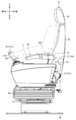
- FIG. 2 is a left side view showing a structure around a driver's seat in the driver's cab in FIG. 1.
- FIG. 5 is a top view showing the operation of the operating lever in FIG. 4 in the front-rear direction.
- FIG. 5 is a top view showing the operation of the operation lever in FIG. 4 in the left-right direction.
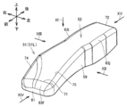
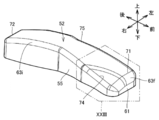
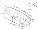
- FIG. 1 It is a figure which shows typically the operation of the left-right operation lever. It is a perspective view showing an armrest. It is another perspective view which shows the armrest. It is a top view which shows the armrest seen in the direction shown by arrow XI in FIG. It is a left side view which shows the armrest seen in the direction indicated by the arrow XII in FIG. It is a right side view which shows the armrest seen in the direction shown by the arrow XIII in FIG. It is a front view which shows the armrest seen in the direction shown by arrow XIV in FIG. It is a rear view which shows the armrest seen in the direction shown by the arrow XV in FIG. FIG.
- FIG. 6 is a left side view showing an operation lever that moves in the front-rear direction and an armrest. It is a left side view which shows typically the movement of the arm of the operator which operates an operation lever in the front-rear direction.
- FIG. 6 is a left side view showing an operation lever and an armrest positioned at a neutral position.
- It is a front view which shows the modification of the shape of the top of the upper surface.
- It is another left side view which shows the structure around the driver's seat in the driver's cab in FIG.
- It is still another left side view which shows the structure around the driver's seat in the driver's cab in FIG.
- FIG. 6 is a front view showing an operation lever that operates in the left-right direction and an armrest.
- FIG. 1 is a perspective view showing a hydraulic excavator according to the embodiment of the present disclosure. First, the overall structure of the hydraulic excavator according to the present embodiment will be described.
- the hydraulic excavator 100 has a vehicle body 11 and a working machine 12.
- the vehicle body 11 includes a revolving structure 13 and a traveling device 15.
- the traveling device 15 has a pair of crawler belts 15Cr and a traveling motor 15M.
- the hydraulic excavator 100 can run by rotating the crawler belt 15Cr.
- the traveling motor 15M is provided as a drive source of the traveling device 15.
- the traveling device 15 may have wheels (tires).
- the swivel body 13 is provided on the traveling device 15.
- the revolving structure 13 can revolve with respect to the traveling device 15 around the revolving center 26.
- the turning center 26 is an axis extending in the vertical direction.
- the swivel body 13 has a driver's cab (cab) 14.
- the operator's cab 14 forms an indoor space in which an operator rides.
- a driver's seat 31 is provided in the driver's cab 14.
- the driver's seat 31 is provided on the floor surface 30 of the driver's cab 14. The operator sits in the driver's seat 31 and operates the hydraulic excavator 100.
- the swivel body 13 has an engine hood 19 and a counterweight provided at the rear of the swivel body 13.
- the engine hood 19 houses an engine, a hydraulic oil tank, an air cleaner, a hydraulic pump, and the like.
- the work machine 12 is attached to the vehicle body 11.
- the working machine 12 is attached to the swivel body 13.
- the work machine 12 performs work such as excavating the ground.
- the work machine 12 includes a boom 16, an arm 17, and a bucket 18.
- the boom 16 is rotatably connected to the vehicle body 11 (swivel body 13) via the boom pin 23.
- the arm 17 is rotatably connected to the boom 16 via an arm pin 24.
- the bucket 18 is rotatably connected to the arm 17 via a bucket pin 25.
- the work machine 12 further includes a boom cylinder 20A and a boom cylinder 20B, an arm cylinder 21, and a bucket cylinder 22.
- Boom cylinder 20A, boom cylinder 20B, arm cylinder 21 and bucket cylinder 22 are hydraulic cylinders driven by hydraulic oil.
- the boom cylinder 20A and the boom cylinder 20B are provided in a pair on both sides of the boom 16, and rotate the boom 16.
- the arm cylinder 21 rotates the arm 17.
- the bucket cylinder 22 rotates the bucket 18.
- the front-rear direction is the front-rear direction of the operator seated in the driver's seat 31.
- the front direction of the operator seated in the driver seat 31 is the front, and the back direction of the operator seated in the driver seat 31 is the rear.
- the left-right direction (lateral direction) is the left-right direction of the operator seated in the driver's seat 31.
- the right side when the operator seated in the driver's seat 31 faces the front is the right side
- the left side when the operator seated in the driver's seat 31 faces the front is the left side.
- the up-down direction is a direction orthogonal to a plane including the front-rear direction and the left-right direction.
- the side with the ground is the bottom and the side with the sky is the top.
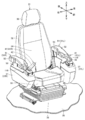
- FIG. 2 and 3 are perspective views showing the structure around the driver's seat in the driver's cab in FIG.
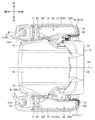
- FIG. 4 is a top view showing the structure around the driver's seat in the driver's cab in FIG.
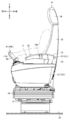
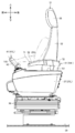
- FIG. 5 is a left side view showing the structure around the driver's seat in the driver's cab in FIG.
- the driver's seat 31 has a seat cushion 33, a seat back 32, a headrest 35, and a suspension mechanism portion 36.
- the seat cushion 33 is a seat portion on which the operator sits down.
- the seat back 32 is provided so as to rise upward from the rear end of the seat cushion 33.
- the seat back 32 is a seat portion that serves as a backrest for the operator.
- the headrest 35 is attached to the upper end of the seat back 32.
- the headrest 35 is a seat portion that supports the operator's head.
- the suspension mechanism portion 36 is provided between the seat cushion 33 and the floor surface 30 in the vertical direction.
- the suspension mechanism portion 36 elastically supports the seat cushion 33.
- the driver's cab 14 has a console 37 (37R, 37L) and an operation lever 41 (41R, 41L).
- the console 37 is provided on the side of the driver's seat 31.
- the console 37R is provided on the right side of the driver's seat 31.
- the console 37L is provided on the left side of the driver's seat 31.
- the console 37R and the console 37L are provided symmetrically on the left and right sides of the driver's seat 31.
- the console 37 has a housing shape.
- the console 37 has a long shape in which the front-rear direction is the longitudinal direction and the left-right direction is the lateral direction in the top view.
- the console 37 is provided in a range that straddles the seat cushion 33 in the vertical direction.
- the console 37 is provided in a range overlapping the seat cushion 33 and the seat back 32 in the front-rear direction.
- the space on the seat cushion 33 is surrounded by the console 37R, the seat back 32, and the console 37L on three sides, the right side, the rear side, and the left side side, respectively, and is open in the front direction.
- the operation lever 41 is provided on the side of the driver's seat 31.
- the operation lever 41R is provided on the right side of the driver's seat 31.
- the operation lever 41L is provided on the left side of the driver's seat 31.
- the operation lever 41R and the operation lever 41L are provided symmetrically on the left and right sides of the driver's seat 31.
- the operation lever 41 is attached to the console 37.
- the operating lever 41 projects upward from the console 37.
- the operation lever 41 is provided closer to the front end of the console 37 than the rear end of the console 37 in a top view.
- the operation lever 41 is provided in front of the seat back 32.
- the operation lever 41 is provided above the seat cushion 33.
- the operation lever 41 has a grip portion 42.
- the grip portion 42 is configured so that the operator can grip it.
- the grip portion 42 extends axially around the central shaft 110.
- the grip portion 42 has a columnar shape centered on the central axis 110.
- the grip portion 42 is erected so that the central shaft 110 extends along the vertical direction.
- the operation lever 41 can be tilted around the lower end side of the grip portion 42.
- the grip portion 42 is not limited to the above-mentioned cylindrical shape, and may be provided in a lateral posture in which the central axis 110 extends in the horizontal direction, or may have a bow-shaped curved shape.
- FIG. 6 is a top view showing the operation of the operation lever in FIG. 4 in the front-back direction.
- FIG. 7 is a top view showing the operation of the operating lever in FIG. 4 in the left-right direction.
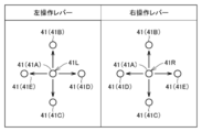
- FIG. 8 is a diagram schematically showing the operation of the left and right operation levers.
- the operating lever 41 operates at least in the front-rear direction.
- the operation lever 41 controls the operation of the work machine 12 when operated by the operator.
- the operating lever 41 can be tilted between the neutral position (41A: the position indicated by the operating lever 41A) and the front position (41B: the position indicated by the operating lever 41B) shifted forward from the neutral position (41A). is there.
- the operating lever 41 can be tilted between the neutral position (41A) and the rear position (41C: the position indicated by the operating lever 41C) shifted rearward from the neutral position (41A).
- the operating lever 41 operates the working machine 12 when positioned at the front position (41B) and the rear position (41C).
- the operating lever 41 automatically returns from the front position (41B) and the rear position (41C) to the neutral position (41A) by receiving an elastic force from, for example, a spring member (not shown).
- the operation lever 41 stops the work machine 12 when positioned at the neutral position (41A).
- the left operating lever 41L when the left operating lever 41L is positioned in the front position (41B), the dump operation of the arm 17 is executed, and when the left operating lever 41L is positioned in the rear position (41C), the arm 17 The excavation operation is executed.
- the right operating lever 41R When the right operating lever 41R is positioned in the front position (41B), the boom 16 is lowered, and when the right operating lever 41R is positioned in the rear position (41C), the boom 16 is raised. To be executed.
- the operation lever 41 operates at least in the direction toward the driver's seat 31.
- the operation lever 41 operates in the left-right direction.
- the operation lever 41 controls the operation of the work machine 12 when operated by the operator.
- the operating lever 41 is located in a neutral position (41A: a position indicated by the operating lever 41A) and a direction approaching the driver's seat 31 along the left-right direction from the neutral position (41A) (hereinafter, "inward along the left-right direction”. It is also possible to tilt between the inside position (41D: the position indicated by the operation lever 41D) shifted to ().
- the operating lever 41 is located in the neutral position (41A) and the outer position (hereinafter, also referred to as "outward along the left-right direction") shifted from the neutral position (41A) in the left-right direction away from the driver's seat 31.
- 41E It can be tilted with respect to the position indicated by the operation lever 41E).
- the operating lever 41 operates the work implement 12 when positioned at the inner position (41D) and the outer position (41E).
- the operating lever 41 automatically returns from the inner position (41D) and the outer position (41E) to the neutral position (41A) by receiving an elastic force from, for example, a spring member (not shown).
- the operation lever 41 stops the work machine 12 when positioned at the neutral position (41A).
- the left operating lever 41L when the left operating lever 41L is positioned in the inner position (41D), the working machine 12 is turned to the right, and when the left operating lever 41L is positioned in the outer position (41E), the working machine 12 is turned to the right. Twelve left turns are performed.
- the right operating lever 41R When the right operating lever 41R is positioned in the inner position (41D), the excavation operation of the bucket 18 is executed, and when the right operating lever 41R is positioned in the outer position (41E), the dumping operation of the bucket 18 is executed. To be done.
- the operation lever 41 can also be tilted to an intermediate position between two positions adjacent to each other in the circumferential direction centered on the neutral position (41A).
- the left operating lever 41L can also be tilted to an intermediate position between the front position (41B) and the outer position (41E). In this case, the dump operation of the arm 17 and the left turning of the working machine 12 are performed. Are executed at the same time.
- the cab 14 further includes armrests 51 (51R, 51L).
- the armrest 51 is provided on the side of the driver's seat 31.
- the armrest 51R is provided on the right side of the driver's seat 31.
- the armrest 51L is provided on the left side of the driver seat 31.
- the armrest 51 is provided behind the operating lever 41.
- the armrest 51R is provided behind the operation lever 41R.
- the armrest 51L is provided behind the operation lever 41L.
- the armrest 51R and the armrest 51L are provided symmetrically on the left and right sides of the driver's seat 31.
- the armrest 51 is attached to the console 37 via the armrest support portion 53.
- the armrest 51 is provided above the console 37. In a top view, the armrest 51 is provided closer to the rear end of the console 37 than the front end of the console 37.
- the armrest 51 is provided above the seat cushion 33.
- the operation lever 41 and the armrest 51 are provided above the console 37 side by side in the front-rear direction.
- the armrest 51 is provided at a position away from the operation lever 41 rearward.
- the armrest 51 is used as an armrest for the operator.
- the armrest 51 includes a metal plate material forming the skeleton of the armrest 51, a cushioning material (urethane foam or the like) having elasticity and covering the plate material, and a cover body wrapping the surface of the cushioning material. It consists of
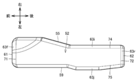
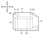
- FIG. 11 is a top view showing the armrest viewed in the direction indicated by arrow XI in FIG.
- FIG. 12 is a left side view showing the armrest viewed in the direction indicated by the arrow XII in FIG. 9.
- FIG. 13 is a right side view showing the armrest viewed in the direction indicated by arrow XIII in FIG. 9.
- FIG. 14 is a front view showing the armrest viewed in the direction indicated by arrow XIV in FIG.
- FIG. 15 is a rear view showing the armrest viewed in the direction indicated by arrow XV in FIG. 9.
- the left armrest 51L and the right armrest 51R have symmetrical shapes.
- the left armrest 51L is shown in FIGS. 9 to 15, and the shape of the armrest 51 will be described below with reference to the left armrest 51L as a representative.
- the armrest 51 has an upper surface 52.
- the upper surface 52 faces upward.
- the upper surface 52 forms an armrest surface on which the operator's elbow is placed.
- the upper surface 52 as a whole has a long shape in which the front-rear direction is the longitudinal direction and the left-right direction is the lateral direction.
- the upper surface 52 has a front end 71, a rear end 72, an inner side end 74, and an outer side end 75.
- the front end 71 is located at the front end of the upper surface 52.
- the rear end 72 is located at the rear end of the upper surface 52.
- the inner end 74 is located at the side end of the upper surface 52 on the side closer to the driver's seat 31 in the left-right direction.
- the outer end 75 is located at the lateral end of the upper surface 52 on the side farther from the driver's seat 31 in the left-right direction.
- the upper surface 52 is provided in a range surrounded by the front end 71, the rear end 72, the inner side end 74, and the outer side end 75.
- the armrest 51 further has a front surface 61, a rear surface 62, an inner side surface 55, and an outer surface 59.
- the front surface 61 faces forward.
- the front surface 61 extends in a plane in the left-right direction.
- the front surface 61 faces the operation lever 41 in the front-rear direction.
- the rear surface 62 faces rearward.
- the rear surface 62 extends laterally in a planar shape.
- the inner side surface 55 faces the driver's seat 31 side in the left-right direction.
- the inner side surface 55 extends in a plane shape in the front-rear direction.
- the front and rear ends of the inner surface 55 are connected to the front surface 61 and the rear surface 62, respectively.
- the outer side surface 59 faces the side opposite to the driver's seat 31 side in the left-right direction.
- the outer side surface 59 extends in a plane shape in the front-rear direction.
- the front end and the rear end of the outer side surface 59 are connected to the front surface 61 and the rear surface 62, respectively.
- the upper ends of the front surface 61, the inner surface 55, the rear surface 62, and the outer surface 59 are connected to the upper surface 52.
- the upper end of the front surface 61 is connected to the front end 71 of the upper surface 52 via a chamfered surface 63f.
- the upper end of the inner side surface 55 is connected to the inner end 74 of the upper surface 52 via the chamfered surface 63i.
- the upper end of the rear surface 62 is connected to the rear end 72 of the upper surface 52 via the chamfered surface 63r.
- the upper end of the outer side surface 59 is connected to the outer end 75 of the upper surface 52 via a chamfered surface 63j.
- the chamfered surface 63f, chamfered surface 63i, chamfered surface 63r, and chamfered surface 63j are curved surfaces.
- the chamfered surface 63f, the chamfered surface 63i, the chamfered surface 63r, and the chamfered surface 63j may be flat surfaces.
- the corners of the front surface 61, the inner side surface 55, the rear surface 62 and the outer surface 59, and the upper surface 52 may not be chamfered as described above.
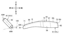
- FIG. 16 is a left side view showing an operation lever that moves in the front-rear direction and an armrest.
- the upper surface 52 further has a forward tilted portion 66 and a backward tilted portion 67.
- the rearwardly inclined portion 67 is provided behind the forwardly inclined portion 66.
- the front tilted portion 66 is located between the operation lever 41 and the back tilted portion 67 in the front-rear direction.
- the height Ha of the forward inclined portion 66 with respect to the floor surface 30 decreases toward the front end 71 of the upper surface 52 in the front-rear direction.
- the height Hb of the rearwardly inclined portion 67 with respect to the floor surface 30 becomes lower toward the rear end 72 of the upper surface 52 in the front-rear direction.
- the upper surface 52 further has a top 73.
- the height Hmax of the topmost portion 73 with respect to the floor surface 30 is the highest among the heights of the upper surface 52 that change depending on the position in the front-rear direction.
- the top portion 73 extends linearly in the left-right direction.
- the top portion 73 extends linearly in the left-right direction.
- the forward tilted portion 66 is provided over a predetermined length from the front end 71 of the upper surface 52 toward the rear.
- the rearward tilting portion 67 is provided over a predetermined length from the rear end 72 of the upper surface 52 toward the front.
- the forward inclined portion 66 is provided across the front end 71 of the upper surface 52 to the top portion 73 in the front-rear direction.
- the rearwardly inclined portion 67 is provided in the front-rear direction from the top portion 73 to the rear end 72 of the upper surface 52.
- the top 73 is not limited to a configuration that extends linearly in the left-right direction in the top view, and may be configured from a horizontal plane provided over a predetermined length in the front-rear direction.
- the forwardly inclined portion 66 and the backwardly inclined portion 67 are provided apart from each other in the front-rear direction via the topmost portion 73.
- the minimum height of the forwardly inclined portion 66 with respect to the floor surface 30 is lower than the minimum height of the backwardly inclined portion 67 with respect to the floor surface 30.
- the minimum height of the forward tilted portion 66 with respect to the floor surface 30 corresponds to the height Hf of the front end 71 with respect to the floor surface 30.
- the maximum height of the forward tilted portion 66 with respect to the floor surface 30 corresponds to the height Hmax of the topmost portion 73 with respect to the floor surface 30.
- the minimum height of the rearwardly inclined portion 67 with respect to the floor surface 30 corresponds to the height Hr of the rear end 72 with respect to the floor surface 30.
- the maximum height of the backward tilted portion 67 with respect to the floor surface 30 corresponds to the height Hmax of the topmost portion 73 with respect to the floor surface 30.
- the length of the forward tilted portion 66 in the front-rear direction (the length between the front end 71 and the top 73 in the front-rear direction) L1 is the length of the rear-tilted portion 67 in the front-rear direction (the top 73 and the rear end in the front-rear direction). (Length between 72) L2 (L1>L2).
- the topmost portion 73 is located closer to the rear end 72 than the front end 71 in the front-rear direction.
- the length L1 of the forward inclined portion 66 in the front-rear direction is at least half the total length L of the armrest 51 in the front-rear direction.
- the length L2 of the rearwardly inclined portion 67 in the front-rear direction is smaller than half the total length L of the armrest 51 in the front-rear direction.
- the sum (L1 + L2) of the length L1 of the forward tilted portion 66 in the front-rear direction and the length L2 of the backward tilted portion 67 in the front-rear direction may be 80% or more of the total length L of the armrest 51 in the front-rear direction. , 90% or more.
- the minimum height of the forward tilted portion 66 based on the floor surface 30 is the same as the minimum height of the backward tilted portion 67 based on the floor surface 30, or the minimum height of the backward tilted portion 67 based on the floor surface 30. It may be higher than the height.
- the length L1 of the forward inclined portion 66 in the front-rear direction may be equal to or less than the length L2 of the rear inclined portion 67 in the front-rear direction (L1 ⁇ L2).
- the top portion 73 may be located in the middle of the front end 71 and the rear end 72 in the front-rear direction, or may be located closer to the front end 71 than the rear end 72.
- the forward inclined portion 66 is composed of a curved surface that extends in the front-rear direction while curving. When viewed in the left-right direction, the forwardly inclined portion 66 extends in an arc shape between the front end 71 and the top portion 73.
- the rearwardly inclined portion 67 is composed of a curved surface that extends in the front-rear direction while curving. When viewed in the left-right direction, the rearwardly inclined portion 67 extends in an arc shape between the topmost portion 73 and the rear end 72.
- the curved surface forming the forwardly inclined portion 66 has a curvature 1/Ra.
- the curved surfaces that form the front inclined portion 66 and the rear inclined portion 67 have a constant curvature from the front end 71 to the rear end 72.
- the curvature 1/Ra may have a size different from the curvature 1/Rb.
- the curvature 1 / Ra may be larger than the curvature 1 / Rb (1 / Ra> 1 / Rb) or smaller than the curvature 1 / Rb (1 / Ra ⁇ 1 / Rb).
- the forward tilted portion 66 has different curvatures from each other, and may be composed of a plurality of curved surfaces arranged in the front-rear direction.
- the rearward tilting portion 67 has different curvatures from each other, and may be composed of a plurality of curved surfaces arranged in the front-rear direction.
- At least one of the forward tilted portion 66 and the backward tilted portion 67 may be composed of a flat surface.
- the forward tilted portion 66 may be configured to include at least one curved surface and at least one plane surface.
- the backward tilted portion 67 may be configured to include at least one curved surface and at least one plane surface.
- the height of the front position (41B) with respect to the floor surface 30 is lower than the height of the neutral position (41A) with respect to the floor surface 30.
- the height of the neutral position (41A) with respect to the floor surface 30 is lower than the height of the rear position (41C) with respect to the floor surface 30.
- the operation lever 41 is tiltable around the rotation center G.
- the grip portion 42 has a tip portion 43W.
- the tip portion 43W is the tip portion of the grip portion 42 when the operating lever 41 is viewed in the left-right direction.
- the tip portion 43W is the end portion of the grip portion 42 located on the side opposite to the side of the rotation center G of the operating lever 41.
- the tip portion 43W and the rotation center G are located on the axis of the central shaft 110.
- the tip 43W of the grip portion 42 when viewed in the left-right direction has an arc shape. Trajectory 120 is drawn and it moves.
- the curvature 1 / Ra of the curved surface forming the forward tilted portion 66 is smaller than the curvature 1 / r of the arcuate locus 120 (1 / Ra ⁇ 1 / r), and constitutes the backward tilted portion 67.
- the curvature 1/Rb of the curved surface is smaller than the curvature 1/r of the arcuate locus 120 (1/Rb ⁇ 1/r).
- the curvature 1 / Ra of the curved surface constituting the forward tilted portion 66 may be equal to or greater than the curvature 1 / r of the arcuate locus 120 (1 / Ra ⁇ 1 / r), and the backward tilted portion 67 is formed.
- the curvature 1/Rb of the curved surface may be 1/r or more of the arcuate locus 120 (1/Rb ⁇ 1/r).
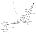
- FIG. 17 is a left side view schematically showing the movement of the arm of the operator who operates the operation lever in the front-back direction.
- the operator holds the grip portion 42 with his / her palm while placing his / her forearm on the upper surface 52 of the armrest 51 to hold the operating lever 41. Manipulate.
- the operator's arm extends forward from the shoulder joint C and diagonally downward, and is bent at the elbow D (Da, Db, Dc).
- the operator's arm (forearm) is tilted forward from the elbow D (Da, Db, Dc) and diagonally downward, closer to horizontal than the tilt between the shoulder joint C and the elbow D (Da, Db, Dc). Is extended by.
- the operator's palm E grips the grip portion 42 of the operating lever 41 at the point where the operator's arm (forearm) extends diagonally downward from the elbow D (Da, Db, Dc). ..
- the operator's arm when the operating lever 41 is positioned in the neutral position (41A) is indicated by a polygonal line 310A
- the operator's arm when the operating lever 41 is positioned in the front position (41B) is indicated by the polygonal line 310B
- the operator's arm when the operating lever 41 is positioned in the rear position (41C) is indicated by the polygonal line 310C.
- the position of the operator's elbow D moves in an arc shape around the shoulder joint C, and the position and inclination of the operator's arm (forearm) change on the upper surface 52 of the armrest 51.
- the upper surface 52 of the armrest 51 is shaped in consideration of the movement of the operator's arm (forearm) when the operation lever 41 is operated in the front-rear direction, so that the operator can smoothly operate the operation lever 41. I have to.
- the upper surface 52 of the armrest 51 has a forward tilted portion 66.
- the height Ha of the forwardly inclined portion 66 with respect to the floor surface 30 decreases toward the front end 71 of the upper surface 52 in the front-rear direction.
- the forward tilting portion 66 has a shape corresponding to the movement of the operator's forearm when the operating lever 41 is tilted forward from the neutral position (41A) to the front side position (41B). The forearm of the operator who operates the lever 41 is less likely to interfere with the upper surface 52.
- the upper surface 52 of the armrest 51 has a backward tilted portion 67.
- the height Hb of the rearwardly inclined portion 67 with respect to the floor surface 30 becomes lower toward the rear end 72 of the upper surface 52 in the front-rear direction.
- the rearward tilting portion 67 has a shape corresponding to the movement of the operator's elbow when the operating lever 41 is tilted backward from the neutral position (41A) to the rearward position (41C). The forearm of the operator who operates the operation lever 41 is less likely to interfere with the upper surface 52.
- the operator can smoothly operate the operating lever 41 between the neutral position (41A) and the front position (41B) and the rear position (41C).
- the forward tilted portion 66 is provided from the front end 71 of the upper surface 52 to the highest portion 73 in the front-rear direction
- the rearward tilted portion 67 is provided at the highest portion 73 in the front-rear direction. It is provided from the surface to the rear end 72 of the upper surface 52.
- the upper surface 52 has a convex shape that protrudes upward between the front end 71 and the rear end 72, so that the shape of the upper surface 52 is changed to the neutral position of the operating lever 41. It can be made to correspond by the movement of the operator's arm when tilting in the front-rear direction between the front position (41B) and the rear position (41C). As a result, the operator can operate the operation lever 41 more smoothly.
- the top 73 and the operator's arm are brought into contact with each other. Excessive frictional resistance may occur in the meantime, or the operator's arm may be caught on the topmost portion 73, which may hinder the movement of the arm.
- the topmost portion 73 extends linearly in the left-right direction in the top view.
- the operator's arm is supported by the top 73 on the upper surface 52 in a linear range along the left-right direction, so that the operator can easily change the inclination of the arm or shift the position of the arm in the front-rear direction.
- the forwardly inclined portion 66 and the backwardly inclined portion 67 are each configured by a curved surface that extends in the front-rear direction while being curved.
- the operator's arm is supported by the forward tilted portion 66 and the backward tilted portion 67 on the upper surface 52 within a linear range along the left-right direction, so that the operator can more easily change the tilt of the arm.
- the position of the arm can be shifted in the front-back direction.
- the curved surface constituting the forward tilted portion 66 and the backward tilted portion 67 has a constant curvature from the front end 71 of the upper surface 52 to the rear end 72 of the upper surface 52.
- FIG. 18 is a left side view showing the operation lever positioned in the neutral position and the armrest.
- the grip portion 42 further has a root portion 44W.
- the root portion 44W is the root portion of the grip portion 42 when the operating lever 41 is viewed in the left-right direction.
- the root portion 44W is an end portion of the grip portion 42 located on the side of the rotation center G of the operating lever 41.
- the root portion 44W is located on the axis of the central shaft 110 when the operation lever 41 is viewed in the left-right direction.
- a virtual straight line 130 extends rearward from the base portion 44W of the operating lever 41 when the operating lever 41 is positioned in the neutral position (41A) and is in contact with the forward tilted portion 66.
- the virtual straight line 130 corresponds to a tangent line that contacts the forward tilted portion 66 extending in an arc shape at the contact point Q.
- the front end 71 of the upper surface 52 is located below the virtual straight line 130.
- the upper arm of the operator holding the grip portion 42 is a virtual straight line from the root portion 44W of the operating lever 41 toward the contact Q. It can be considered to be placed above 130.
- the operator's arm placed on the upper surface 52 is likely to be arranged at a position away from the front end 71 of the upper surface 52. ..
- the operator's arm is less likely to be caught by the front end 71 of the upper surface 52.
- FIG. 19 is a front view showing a modification of the shape of the topmost portion of the upper surface.
- FIG. 19 is a diagram corresponding to FIG.
- the top portion 73 is curved downward in the left-right direction when viewed from the front.
- the topmost portion 73 extends in the left-right direction while curving.
- the top portion 73 has an arc shape that is convex upward.
- the upper surface 52 is smoothly connected between the top 73 and the front and rear positions of the top 73.
- the operator can easily move the arm placed on the upper surface 52 in the left-right direction. Therefore, the operator can smoothly operate the operating lever 41 between the neutral position (41A) and the inner position (41D) and the outer position (41E) (see FIG. 7).
- the upper surface 52 further has a front portion 52F and a rear portion 52R.
- the front portion 52F is provided over a predetermined length from the front end 71 toward the rear.
- the rear portion 52R is provided over a predetermined length from the rear end 72 toward the front.
- Width B1 of front part 52F of upper surface 52 is larger than width of rear part 52R of upper surface 52 (B1>B2).
- the length in the left-right direction is called the width.
- the front portion 52F of the upper surface 52 projects in the left-right direction toward the driver's seat 31 than the rear portion 52R of the upper surface 52.
- the length in the left-right direction from the center line 101 of the driver's seat 31 extending in the front-rear direction to the inner end 74 of the front portion 52F of the upper surface 52 is the rear of the upper surface 52 from the center line 101 of the driver's seat 31 extending in the front-rear direction. It is smaller than the length in the left-right direction up to the inner end 74 of the portion 52R.
- the width B1 of the front portion 52F of the upper surface 52 is larger than the width B2 of the rear portion 52R of the upper surface 52.
- 20 and 21 are left side views showing the structure around the driver's seat in the driver's cab in FIG.
- the driver's seat 31 is provided slidably in the front-rear direction.
- the driver's seat 31 is provided slidably in the front-rear direction independently of the console 37, the operation lever 41, and the armrest 51.
- the driver's seat 31 is positioned in any position between the front end position shown in FIG. 20, the intermediate position shown in FIG. 5, and the rear end position shown in FIG. 21 by sliding in the front-rear direction. Will be done. With such a configuration, the position of the driver's seat 31 in the front-rear direction can be adjusted according to the physique of the operator.
- FIG. 20 shows the arm of an operator having a small physique
- FIG. 5 shows the arm of an operator having a medium physique
- FIG. 21 shows the arm of an operator having a large physique. It is shown.
- the smaller the physique the shorter the length of the operator's arm. Therefore, when the operation lever 41 is operated, the position 250 (see FIG. 5) at which the elbow of the operator having a medium physique is placed on the armrest 51. , The elbow of the operator with a large physique shifts forward from position 260 (see FIG. 21) where the armrest 51 is placed. Further, the position 255 (see FIG. 20) where the elbow of the operator having a smaller physique is placed on the armrest 51 is more than the position 250 (see FIG. 5) where the elbow of the operator having a medium physique is placed on the armrest 51. Shift forward.
- FIG. 22 is a front view showing seated states of operators having different physiques.
- the case where the operator 230 having a large physique is seated in the driver's seat 31 the case where the operator 220 having a medium physique is seated, and the case where the operator 210 having a small physique is seated are compared. ing.
- the position 215 where the elbow of the operator 210 having a small physique is placed on the armrest 51 shifts inward along the left-right direction from the position 225 where the elbow of the operator 220 having a medium physique is placed on the armrest 51.
- the front portion 52F of the upper surface 52 projects in the left-right direction closer to the driver's seat 31 than the rear portion 52R of the upper surface 52.
- the armrest 51 is left and right on the rear portion 52R side of the front portion 52F side. In the direction, it may be in a form of retreating in the direction away from the driver's seat 31. Accordingly, when an operator having a particularly large physique is seated in the driver's seat 31, a wide space is secured between the operator's waist and the armrest 51, so that the operator's waist is pressed by the armrest 51. Can be suppressed.
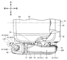
- FIG. 23 is a perspective view showing an armrest in the range surrounded by the alternate long and short dash line XXIII in FIG.
- FIG. 24 is a cross-sectional view showing an armrest seen in the direction of arrow on the line XXIV-XXIV in FIG. 23.
- the front portion 52F of the upper surface 52 has an inclined portion 81.
- the height Hs of the inclined portion 81 with respect to the floor surface 30 becomes lower toward the driver's seat 31.
- the height Hs of the inclined portion 81 with respect to the floor surface 30 decreases in the left-right direction toward the driver's seat 31.
- the inclined portion 81 is provided at the corner of the front end 71 and the inner end 74 of the upper surface 52.
- the inclined portion 81 is provided in front of the top portion 73 (see FIG. 16).
- the inclined portion 81 is a part of the forward inclined portion 66 (see FIG. 16).
- the inclined portion 81 is provided at a position separated inward along the left-right direction from the outer end 75 of the upper surface 52.
- the inclined portion 81 corresponds to the range surrounded by the three sides connecting the points S1, S2, and S3 in FIG.
- the point S1 is on the inner end 74 and is located rearward from the front end 71.
- the point S2 is on the front end 71 and is located between the inner end 74 and the outer end 75 in the left-right direction.
- the point S2 may be located closer to the outer end 75 than the inner end 74 in the left-right direction, may be located between the inner end 74 and the outer end 75, or may be located between the inner end 74 and the outer end 75. It may be located closer to the inner end 74 than.
- the point S3 is located at the intersection of the inner end 74 and the front end 71.
- the length between the points S1 and S3 is larger than the length between the points S3 and S2.
- the length between the points S1 and S3 may be less than or equal to the length between the points S3 and S2.
- the width F of the inclined portion 81 increases toward the front end 71 of the upper surface 52 in the front-rear direction.
- the height Hs of the inclined portion 81 with respect to the floor surface 30 decreases from the side connecting the points S1 and S2 toward the driver's seat 31 in the left-right direction.
- the height Hs of the inclined portion 81 with respect to the floor surface 30 decreases from the side connecting the points S1 and S2 toward the front.
- the height Hs of the inclined portion 81 with respect to the floor surface 30 is highest at the point S1 and lowest at the point S3.
- the front portion 52F of the upper surface 52 further has a horizontal portion 82.
- the horizontal portion 82 and the inclined portion 81 are provided side by side in the left-right direction.
- the horizontal portion 82 is provided on the opposite side of the driver seat 31 with the inclined portion 81 interposed therebetween in the left-right direction.
- the horizontal portion 82 is connected to the inclined portion 81 (the side connecting the points S1 and S2).
- the horizontal portion 82 extends horizontally in the left-right direction.
- the horizontal portion 82 is connected to the inclined portion 81 at one end that extends horizontally in the left-right direction.
- the inclined portion 81 makes an angle ⁇ with a horizontal line extending from the horizontal portion 82.
- the angle ⁇ is in the range of 0° ⁇ 90°.
- the angle ⁇ may be in the range of 5° ⁇ 30°.
- FIG. 25 is a front view showing an operation lever that moves left and right and an armrest. As shown in FIGS. 23 to 25, the height of the inner position (41D) with respect to the floor surface 30 is lower than the height of the neutral position (41A) with respect to the floor surface 30. The height of the neutral position (41A) with respect to the floor surface 30 is lower than the height of the outer position (41E) with respect to the floor surface 30.
- the operation region (hatched region 360 in FIG. 25) of the operation lever 41 between the neutral position (41A) and the inner position (41D) overlaps the inclined portion 81.
- the operation lever 41 positioned at the neutral position (41A) is aligned with the horizontal portion 82 in the left-right direction.
- the front end 71 of the upper surface 52 overlaps the operating lever 41 positioned at the outer position (41E) in the range where the front end 71 is connected to the horizontal portion 82.
- the operating lever 41 positioned in the neutral position (41A) and the inner position (41D) overlaps the front end 71 in the range where the front end 71 is connected to the inclined portion 81.
- the operator grips the grip portion 42 from the side opposite to the driver's seat 31 in the left-right direction with his/her own palm (left hand), and operates the operation lever 41 by moving the operation lever 41 to the neutral position (41A), the inner position (41D) and the outer position. Tilt to the left and right with (41E).
- the position of the operator's wrist changes on the upper surface 52 of the armrest 51.
- the upper surface 52 of the armrest 51 has a shape that takes into account the movement of the wrist of the operator when the operation lever 41 is moved in the left-right direction, thereby facilitating the operation of the operation lever 41 by the operator. ..
- the front portion 52F of the upper surface 52 has the inclined portion 81.
- the height Hs of the inclined portion 81 with respect to the floor surface 30 becomes lower toward the driver's seat 31 in the left-right direction.
- the inclined portion 81 has a shape corresponding to the movement of the operator's wrist when the operation lever 41 is tilted inward in the left-right direction from the neutral position (41A) to the inner position (41D). Therefore, the forearm of the operator who operates the operation lever 41 is less likely to interfere with the upper surface 52. This allows the operator to smoothly operate the operation lever 41 between the neutral position (41A) and the inner position (41D).
- the operating area of the operating lever 41 between the neutral position (41A) and the inner position (41D) overlaps with the inclined portion 81.
- the front part 52F of the upper surface 52 further has a horizontal part 82.
- the horizontal portion 82 is provided on the opposite side of the driver seat 31 with the inclined portion 81 interposed therebetween in the left-right direction.
- the width F of the inclined portion 81 increases toward the front end 71 of the upper surface 52 in the front-rear direction.
- the tilt angle of the operation lever 41 between the neutral position (41A) and the inner position (41D) is ⁇ .
- the angle ⁇ formed by the inclined portion 81 with the horizontal line extending the horizontal portion 82 is equal to the tilt angle ⁇ of the operating lever 41.
- the operation lever 41 (grip portion 42) has a tip portion 43V.
- the tip portion 43V is the tip portion of the operating lever 41 (grip portion 42) when the operating lever 41 is viewed in the front-rear direction.
- the tip portion 43V is the end portion of the operating lever 41 (grip portion 42) located on the side opposite to the side of the rotation center G of the operating lever 41.
- the tip portion 43V is located on the axis of the central shaft 110.
- the tip 43V of the operating lever 41 when viewed in the front-rear direction moves in an arcuate locus 380.
- the inclined portion 81 may have the same shape as the arc-shaped locus 380 drawn by the tip portion 43V of the operating lever 41.
- the shape of the inclined portion 81 can be made to correspond to the movement of the operator's wrist when the operating lever 41 is operated from the neutral position (41A) to the inner position (41D). As a result, the operator can operate the operation lever 41 more smoothly.
- the angle ⁇ formed by the inclined portion 81 and the horizontal line extending from the horizontal portion 82 may be smaller than the tilt angle ⁇ of the operating lever 41 or may be larger than the tilt angle ⁇ of the operating lever 41.
- the driver's cab 14 includes a driver's seat 31, an operation lever 41 as an operation unit, and an armrest 51.
- the driver's seat 31 is provided on the floor surface 30.
- the operation lever 41 is provided on the side of the driver's seat 31.
- the operating lever 41 operates in a direction at least approaching the driver's seat 31.
- the armrest 51 has an upper surface 52.
- the armrest 51 is provided on the side of the driver's seat 31 and behind the operation lever 41.
- the width of the front portion 52F of the upper surface 52 is larger than the width of the rear portion 52R of the upper surface 52.
- the front portion 52F of the upper surface 52 has an inclined portion 81.
- the height of the inclined portion 81 with respect to the floor surface 30 becomes lower toward the driver's seat 31.
- the width of the front portion 52F of the upper surface 52 is larger than the width of the rear portion 52R of the upper surface 52, so that the operator who swings inward in the left-right direction in accordance with the operation of the operation lever 41 can be used.
- the arm can be continuously supported by the front portion 52F of the upper surface 52.
- an operator who operates the operation lever 41 is provided on the front portion 52F of the upper surface 52 by providing the inclined portion 81 corresponding to the movement of the operator's arm when the operation lever 41 is moved toward the driver's seat 31. The arm is less likely to interfere with the upper surface 52. For these reasons, the operator can smoothly operate the operation lever 41.
- the front portion 52F of the upper surface 52 projects in a direction closer to the driver's seat 31 than the rear portion 52R of the upper surface 52.
- an operator with a small physique places his elbow on the front portion 52F of the upper surface 52 to operate the operation lever 41, and an operator with a large physique places his elbow on the rear portion 52R of the upper surface 52 to operate.
- the lever 41 can be operated. Therefore, the operator can smoothly operate the operation lever 41 regardless of his / her physique.
- the operation lever 41 is at least between a neutral position (41A) as a first position and an inner position (41D) as a second position that is shifted from the neutral position (41A) toward the driver seat 31. It is an operation lever that can be tilted.
- the height of the inner position (41D) with respect to the floor surface 30 is lower than the height of the neutral position (41A) with respect to the floor surface 30.
- the operation lever 41 can be further tilted between a neutral position (41A) and an outer position (41E) as a third position shifted from the neutral position (41A) in a direction away from the driver seat 31.
- the height of the outer position (41E) with respect to the floor surface 30 is higher than the height of the neutral position (41A) with respect to the floor surface 30.
- the front portion 52F of the upper surface 52 further has a horizontal portion 82.
- the horizontal portion 82 is provided on the opposite side of the driver's seat 31 with the inclined portion 81 interposed therebetween in the left-right direction.
- the horizontal portion 82 is connected to the inclined portion 81.
- the inclined portion 81 makes an angle ⁇ (0° ⁇ 90°) with the horizontal line extending the horizontal portion 82.
- the angle ⁇ is equal to the tilt angle ⁇ of the operating lever 41 between the neutral position (41A) and the inner position (41D).
- the tip portion 43V of the operation lever 41 when viewed in the front-rear direction moves along an arcuate locus 380. ..
- the inclined portion 81 may have the same shape as the arc-shaped locus 380 drawn by the tip portion 43V of the operating lever 41.
- the shape of the inclined portion 81 can be made to correspond to the movement of the operator's arm when the operation lever 41 is operated from the neutral position (41A) to the inner position (41D).
- the arm of the operator who operates the operation lever 41 is less likely to interfere with the upper surface 52, so that the operator can smoothly operate the operation lever 41 between the neutral position (41A) and the inner position (41D). Can be done.
- the width F of the inclined portion 81 increases toward the front end 71 of the upper surface 52 in the front-rear direction.
- the swing width of the operator's arm in the left-right direction increases as it approaches the wrist and decreases as it approaches the elbow. Therefore, the width of the inclined portion 81 can be made to correspond to the movement of the operator's upper arm. As a result, the operator's arm is less likely to interfere with the upper surface 52, so that the operator can smoothly operate the operation lever 41.
- the hydraulic excavator 100 as a work vehicle includes a driver's cab 14 and a work machine 12.
- the working machine 12 is controlled by the operating lever 41.
- the operator can smoothly operate the operation lever 41 when controlling the work machine 12.
- the present disclosure is not limited to the cab of a hydraulic excavator, but is applied to the cab of various work vehicles including armrests for armrests of operators.
Landscapes
- Engineering & Computer Science (AREA)
- Aviation & Aerospace Engineering (AREA)
- Transportation (AREA)
- Mechanical Engineering (AREA)
- Mining & Mineral Resources (AREA)
- Civil Engineering (AREA)
- General Engineering & Computer Science (AREA)
- Structural Engineering (AREA)
- Component Parts Of Construction Machinery (AREA)
- Mechanical Control Devices (AREA)
- Seats For Vehicles (AREA)
Abstract
Description
図1は、本開示の実施の形態における油圧ショベルを示す斜視図である。まず、本実施の形態における油圧ショベルの全体構造について説明する。
(アームレストの全体形状について)
続いて、アームレスト51のより具体的な形状について説明する。図9および図10は、アームレストを示す斜視図である。図11は、図9中の矢印XIに示す方向に見たアームレストを示す上面図である。図12は、図9中の矢印XIIに示す方向に見たアームレストを示す左側面図である。図13は、図9中の矢印XIIIに示す方向に見たアームレストを示す右側面図である。図14は、図9中の矢印XIVに示す方向に見たアームレストを示す前面図である。図15は、図9中の矢印XVに示す方向に見たアームレストを示す後面図である。
図16は、前後方向に動作する操作レバーと、アームレストとを示す左側面図である。
図4および図7に示されるように、上面52は、前方部52Fと、後方部52Rとをさらに有する。前方部52Fは、前方端71から後方に向けて所定長さに渡って設けられている。後方部52Rは、後方端72から前方に向けて所定長さに渡って設けられている。
床面30を基準とする傾斜部81の高さHsは、点S1および点S2を結ぶ辺から、左右方向において運転席31に向かうと低くなる。床面30を基準とする傾斜部81の高さHsは、点S1および点S2を結ぶ辺から前方に向かうと低くなる。床面30を基準とする傾斜部81の高さHsは、点S1で最も高くなり、点S3で最も低くなる。
図23から図25に示されるように、床面30を基準とする内側ポジション(41D)の高さは、床面30を基準とする中立ポジション(41A)の高さよりも低い。床面30を基準とする中立ポジション(41A)の高さは、床面30を基準とする外側ポジション(41E)の高さよりも低い。
運転室14は、運転席31と、操作部としての操作レバー41と、アームレスト51とを備える。運転席31は、床面30上に設けられる。操作レバー41は、運転席31の側方に設けられる。操作レバー41は、少なくとも運転席31に近づく方向に動作する。アームレスト51は、上面52を有する。アームレスト51は、運転席31の側方、かつ、操作レバー41の後方に設けられる。上面52の前方部52Fの幅は、上面52の後方部52Rの幅よりも大きい。上面52の前方部52Fは、傾斜部81を有する。床面30を基準とする傾斜部81の高さは、運転席31に向かうに従って低くなる。
Claims (8)
- 床面上に設けられる運転席と、
前記運転席の側方に設けられ、少なくとも前記運転席に近づく方向に動作する操作部と、
上面を有し、前記運転席の側方、かつ、前記操作部の後方に設けられるアームレストとを備え、
前記上面の前方部の幅は、前記上面の後方部の幅よりも大きく、
前記上面の前方部は、傾斜部を有し、
前記床面を基準とする前記傾斜部の高さは、前記運転席に向かうに従って低くなる、運転室。 - 前記上面の前方部は、前記上面の後方部よりも、前記運転席に近づく方向に張り出している、アームレストを備えた請求項1に記載の運転室。
- 前記操作部は、少なくとも、第1ポジションと、前記第1ポジションから前記運転席に近づく方向にシフトした第2ポジションとの間で傾倒可能な操作レバーであり、
前記床面を基準とする前記第2ポジションの高さは、前記床面を基準とする前記第1ポジションの高さよりも低く、
前後方向に見た場合に、前記第1ポジションおよび前記第2ポジションの間における前記操作レバーの動作領域が、前記傾斜部と重なっている、請求項1または2に記載の運転室。 - 前記操作レバーは、前記第1ポジションと、前記第1ポジションから前記運転席から遠ざかる方向にシフトした第3ポジションとの間でさらに傾倒可能であり、
前記床面を基準とする前記第3ポジションの高さは、前記床面を基準とする前記第1ポジションの高さよりも高く、
前記上面の前方部は、左右方向において、前記傾斜部を挟んで前記運転席の反対側に設けられ、前記傾斜部に接続される水平部をさらに有する、アームレストを備えた請求項3に記載の運転室。 - 前後方向に直交する平面により切断された前記アームレストの断面において、前記傾斜部は、前記水平部を延長した水平線と角度α(0°<α<90°)をなし、
前記角度αは、前記第1ポジションおよび前記第2ポジションの間における前記操作レバーの傾倒角度と等しい、請求項4に記載の運転室。 - 前記操作レバーが前記第1ポジションおよび前記第2ポジションの間で動作する間に、前後方向に見た時の前記操作レバーの先端部が円弧状の軌跡を描いて移動し、
前後方向に直交する平面により切断された前記アームレストの断面において、前記傾斜部は、前記円弧状の軌跡と同一形状を有する、請求項3に記載の運転室。 - 前記傾斜部の幅は、前後方向において前記上面の前方端に向かうと大きくなる、アームレストを備えた請求項1に記載の運転室。
- 請求項1に記載の運転室と、
前記操作部により制御される作業機とを備える、作業車両。
Priority Applications (4)
| Application Number | Priority Date | Filing Date | Title |
|---|---|---|---|
| CN202080013543.0A CN113412074B (zh) | 2019-03-01 | 2020-02-26 | 驾驶室以及作业车辆 |
| KR1020217025155A KR102626935B1 (ko) | 2019-03-01 | 2020-02-26 | 운전실 및 작업 차량 |
| US17/310,916 US11993915B2 (en) | 2019-03-01 | 2020-02-26 | Operator's cab and work vehicle |
| DE112020000338.8T DE112020000338B4 (de) | 2019-03-01 | 2020-02-26 | Fahrerkabine und Arbeitsfahrzeug |
Applications Claiming Priority (2)
| Application Number | Priority Date | Filing Date | Title |
|---|---|---|---|
| JP2019-037958 | 2019-03-01 | ||
| JP2019037958A JP7338990B2 (ja) | 2019-03-01 | 2019-03-01 | 運転室および作業車両 |
Publications (1)
| Publication Number | Publication Date |
|---|---|
| WO2020179566A1 true WO2020179566A1 (ja) | 2020-09-10 |
Family
ID=72279809
Family Applications (1)
| Application Number | Title | Priority Date | Filing Date |
|---|---|---|---|
| PCT/JP2020/007636 Ceased WO2020179566A1 (ja) | 2019-03-01 | 2020-02-26 | 運転室および作業車両 |
Country Status (6)
| Country | Link |
|---|---|
| US (1) | US11993915B2 (ja) |
| JP (1) | JP7338990B2 (ja) |
| KR (1) | KR102626935B1 (ja) |
| CN (1) | CN113412074B (ja) |
| DE (1) | DE112020000338B4 (ja) |
| WO (1) | WO2020179566A1 (ja) |
Families Citing this family (1)
| Publication number | Priority date | Publication date | Assignee | Title |
|---|---|---|---|---|
| JP7338989B2 (ja) * | 2019-03-01 | 2023-09-05 | 株式会社小松製作所 | 運転室および作業車両 |
Citations (3)
| Publication number | Priority date | Publication date | Assignee | Title |
|---|---|---|---|---|
| JPH10252100A (ja) * | 1997-03-13 | 1998-09-22 | Kawasaki Heavy Ind Ltd | 建設車両の操作用ジョイスティック装置 |
| JPH11296246A (ja) * | 1998-04-06 | 1999-10-29 | Nissan Motor Co Ltd | 車両用運転操作装置 |
| US20160355111A1 (en) * | 2015-08-17 | 2016-12-08 | Caterpillar Inc. | Control system for a seat |
Family Cites Families (21)
| Publication number | Priority date | Publication date | Assignee | Title |
|---|---|---|---|---|
| GB796613A (en) * | 1955-11-16 | 1958-06-18 | Mabel Louise Laver | Improvements in or relating to arm rests |
| NZ194573A (en) | 1979-08-31 | 1984-07-06 | Massey Ferguson Services Nv | Cab for agricultural industrial or construction vehicle:door hinge axis inclined |
| JP3783189B2 (ja) | 1998-05-08 | 2006-06-07 | 株式会社小松製作所 | ステアリング操作装置 |
| JP3352041B2 (ja) | 1998-11-11 | 2002-12-03 | 株式会社小松製作所 | 作業車両のモノレバー操縦装置 |
| USH1831H (en) * | 1998-12-18 | 2000-02-01 | Caterpillar Inc. | Ergonomic motor grader vehicle control apparatus |
| JP4699884B2 (ja) | 2005-12-01 | 2011-06-15 | 株式会社小松製作所 | コンソールボックス |
| US20080023250A1 (en) | 2006-07-31 | 2008-01-31 | Hefner Robert E | Ergonomic machine control console |
| CN101289068A (zh) | 2008-03-18 | 2008-10-22 | 刘旗周 | 乘用车 |
| US20100052356A1 (en) * | 2008-09-04 | 2010-03-04 | Caterpillar Inc. | Suspension system for a seat assembly including an array of fluid chambers and machine using same |
| JP5275128B2 (ja) | 2009-05-11 | 2013-08-28 | ヤンマー株式会社 | 操作ユニット |
| US8714049B2 (en) | 2011-02-11 | 2014-05-06 | Cnh Industrial America Llc | Adjustable control system |
| JP2013183682A (ja) | 2012-03-07 | 2013-09-19 | Kubota Corp | 作業車 |
| GB2514356B (en) * | 2013-05-20 | 2017-01-11 | William Mcmillan Nigel | An armrest and armrest pad |
| US10555372B2 (en) * | 2016-05-09 | 2020-02-04 | Daechang Co., Ltd. | Armrest and control method for the same |
| US10569881B2 (en) * | 2016-10-18 | 2020-02-25 | Molon Labe, Llc | Staggered aircraft seat assembly |
| US11540439B2 (en) * | 2018-07-18 | 2023-01-03 | Ariens Company | Lawn mower including a control panel and movable seat |
| EP3966048A4 (en) * | 2019-05-09 | 2022-08-10 | Ariens Company | COMMERCIAL VEHICLE SUSPENSION SYSTEM |
| WO2021080628A1 (en) * | 2019-10-25 | 2021-04-29 | Safran Seats Usa Llc | Passenger seat armrest with a multi-zone top surface |
| US11447052B2 (en) * | 2020-03-13 | 2022-09-20 | Caterpillar Paving Products Inc. | Adjustable width control pod bracket assembly |
| JP7777816B2 (ja) * | 2021-08-05 | 2025-12-01 | スターテング工業株式会社 | アームレスト構造 |
| KR102509694B1 (ko) * | 2021-09-16 | 2023-03-14 | 주식회사 다온티앤티 | 캠핑카용 보조의자 |
-
2019
- 2019-03-01 JP JP2019037958A patent/JP7338990B2/ja active Active
-
2020
- 2020-02-26 KR KR1020217025155A patent/KR102626935B1/ko active Active
- 2020-02-26 CN CN202080013543.0A patent/CN113412074B/zh active Active
- 2020-02-26 US US17/310,916 patent/US11993915B2/en active Active
- 2020-02-26 WO PCT/JP2020/007636 patent/WO2020179566A1/ja not_active Ceased
- 2020-02-26 DE DE112020000338.8T patent/DE112020000338B4/de active Active
Patent Citations (3)
| Publication number | Priority date | Publication date | Assignee | Title |
|---|---|---|---|---|
| JPH10252100A (ja) * | 1997-03-13 | 1998-09-22 | Kawasaki Heavy Ind Ltd | 建設車両の操作用ジョイスティック装置 |
| JPH11296246A (ja) * | 1998-04-06 | 1999-10-29 | Nissan Motor Co Ltd | 車両用運転操作装置 |
| US20160355111A1 (en) * | 2015-08-17 | 2016-12-08 | Caterpillar Inc. | Control system for a seat |
Also Published As
| Publication number | Publication date |
|---|---|
| CN113412074B (zh) | 2024-11-12 |
| KR20210113315A (ko) | 2021-09-15 |
| JP2020138711A (ja) | 2020-09-03 |
| US20220136209A1 (en) | 2022-05-05 |
| DE112020000338T5 (de) | 2021-09-23 |
| DE112020000338B4 (de) | 2026-03-12 |
| US11993915B2 (en) | 2024-05-28 |
| JP7338990B2 (ja) | 2023-09-05 |
| KR102626935B1 (ko) | 2024-01-17 |
| CN113412074A (zh) | 2021-09-17 |
Similar Documents
| Publication | Publication Date | Title |
|---|---|---|
| JP7244252B2 (ja) | 作業車両 | |
| EP3396073B1 (en) | Device for operating construction machine | |
| JP7195872B2 (ja) | 作業車両 | |
| CN107306508A (zh) | 作业车辆的操作装置 | |
| WO2016199190A1 (ja) | キャブおよびブルドーザ | |
| WO2020179565A1 (ja) | 運転室および作業車両 | |
| US20080023250A1 (en) | Ergonomic machine control console | |
| JP7201350B2 (ja) | 作業機械およびモータグレーダ | |
| WO2020179566A1 (ja) | 運転室および作業車両 | |
| KR102623758B1 (ko) | 소형 로더 | |
| US20250034840A1 (en) | Cab and work machine | |
| JP6026143B2 (ja) | 旋回作業機 | |
| JP7318144B2 (ja) | 作業機 | |
| JP2006006721A (ja) | 建設機械の運転装置 | |
| JP2023155554A (ja) | 作業機械およびキャブ | |
| JPH0827839A (ja) | 建設機械の操縦装置 | |
| JP2026059399A (ja) | 運転室および作業機械 | |
| JPWO2025063236A5 (ja) | ||
| WO2025063236A1 (ja) | 作業機 | |
| JP2000257119A (ja) | 建設機械の運転室 |
Legal Events
| Date | Code | Title | Description |
|---|---|---|---|
| 121 | Ep: the epo has been informed by wipo that ep was designated in this application |
Ref document number: 20765600 Country of ref document: EP Kind code of ref document: A1 |
|
| WWE | Wipo information: entry into national phase |
Ref document number: 112020000338 Country of ref document: DE |
|
| ENP | Entry into the national phase |
Ref document number: 20217025155 Country of ref document: KR Kind code of ref document: A |
|
| 122 | Ep: pct application non-entry in european phase |
Ref document number: 20765600 Country of ref document: EP Kind code of ref document: A1 |
|
| WWG | Wipo information: grant in national office |
Ref document number: 112020000338 Country of ref document: DE |