WO2020174844A1 - ロボットハンド - Google Patents
ロボットハンド Download PDFInfo
- Publication number
- WO2020174844A1 WO2020174844A1 PCT/JP2019/050144 JP2019050144W WO2020174844A1 WO 2020174844 A1 WO2020174844 A1 WO 2020174844A1 JP 2019050144 W JP2019050144 W JP 2019050144W WO 2020174844 A1 WO2020174844 A1 WO 2020174844A1
- Authority
- WO
- WIPO (PCT)
- Prior art keywords
- cam
- bracket
- holding member
- shaft holding
- robot hand
- Prior art date
Links
Images


Classifications
-
- B—PERFORMING OPERATIONS; TRANSPORTING
- B25—HAND TOOLS; PORTABLE POWER-DRIVEN TOOLS; MANIPULATORS
- B25J—MANIPULATORS; CHAMBERS PROVIDED WITH MANIPULATION DEVICES
- B25J15/00—Gripping heads and other end effectors
- B25J15/08—Gripping heads and other end effectors having finger members
Definitions
- the present invention relates to a robot hand.
- Patent Document 1 describes a robot hand including a claw member.
- a cam follower is formed on the claw member so as to swing when the cam is driven.
- the positional accuracy of the claw member may decrease.
- an object of the present invention is to provide a robot hand in which the positional accuracy of the claw member is improved.
- the above object is to provide a cam driven by a drive source, a bracket accommodating the cam, a pawl member having a cam follower that abuts on the cam and swinging around a predetermined axis in response to the driving of the cam,
- a support shaft portion that rotatably supports a claw member with respect to the bracket; a shaft holding member that rotatably holds the support shaft portion and that is supported by the bracket so as to be movable to the cam side;
- This can be achieved by a robot hand including a pressing member that presses the shaft holding member toward the cam so that the cam follower is pressed toward the cam.
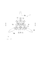
- FIG. 1 is a perspective view of a robot hand.
- 2A to 2D are external views of the claw member.
- FIG. 3 is an enlarged perspective view of the bracket.
- FIG. 4 is an enlarged perspective view of the cam.
- FIG. 5 is a front view of the robot hand.
- FIG. 6 is a sectional view taken along line AA of FIG.
- FIG. 7 is an enlarged view of FIG.
- FIG. 8 is an explanatory diagram of the first modification.
- FIG. 9 is an explanatory diagram of the second modified example.
- FIG. 1 is a perspective view of the robot hand 1.
- FIG. 1 shows an X direction, a Y direction and a Z direction which are orthogonal to each other.
- the robot hand 1 includes a motor 3, a bracket 10, an attachment 20, and claw members 30a to 30c.
- the motor 3 is a drive source for opening and closing the claw members 30a to 30c, and is, for example, a stepping motor, but is not limited to this. In FIG. 1, the illustration of the motor 3 is simplified.
- the bracket 10 is attached to the tip side of the motor 3.
- the claw members 30a to 30c are swingably held by the bracket 10.
- the claw members 30a to 30c are arranged at equal angular intervals around a central axis A1 parallel to the Z direction.
- the claw members 30a to 30c are the same members, but different reference numerals are attached for convenience of description.
- the attachment 20 is attached to the center of the front end side of the bracket 10.
- the attachment 20 is formed with an opening 22 so that the central axis A1 passes therethrough.
- a camera, an air suction/jetting device, or the like can be mounted in the opening 22, for example.
- FIGS. 2A to 2D are external views of the claw member 30a.
- a cam follower 33 with which a cam 40 described later is engaged is formed in a bifurcated shape.
- a through hole that penetrates in a direction perpendicular to the plane including the direction in which the claw member 30a swings is provided, and the support shaft 35 is fitted into the through hole so as not to slide. I am fit.
- Bearings 38 are attached to both ends of the support shaft 35 protruding from the claw member 30a. With such a mechanism, the claw member 30a is held by the bracket 10 so as to be able to swing within a predetermined range around the swing axis A2.
- the bearing 38 is an example of a shaft holding member.
- FIG. 3 is an enlarged perspective view of the bracket 10.
- the attachment 20 is removed from the bracket 10.
- a slit opening 12 formed of three slits radially extending around the central axis A1 is formed.
- the attachment 20 is attached to the bracket 10 so as to close the slit opening 12.
- the bracket 10 has a holding space 18a for holding the bearing 38 of the claw member 30a so as to be movable in a predetermined range in the Z direction. Similarly, holding spaces 18b and 18c are formed in the claw members 30b and 30c, respectively. Further, the bracket 10 is formed with two screw holes 17a extending in the Z direction so as to sandwich the claw member 30a. Similarly, the bracket 10 is formed with two screw holes 17b so as to sandwich the claw member 30b and two screw holes 17c so as to sandwich the claw member 30c.
- FIG. 4 is an enlarged perspective view of the cam 40.
- the cam 40 is housed in the bracket 10 and includes a base portion 41 and three-dimensional cam portions 43a to 43c.
- the base portion 41 is formed in a disc shape, and an opening 42 is formed at the center thereof.
- the three-dimensional cam portions 43a to 43c are formed so as to stand up from one surface of the base portion 41.
- the three-dimensional cam portion 43a extends in a substantially arc shape so as to extend from the opening 42 side to the outer peripheral side of the base portion 41.
- the bifurcated cam follower 33 of the claw member 30a is engaged so as to sandwich the solid cam portion 43a.
- each of the three-dimensional cam portions 43a to 43c has one end 43a1 to 43c1 located near the opening 42 and the other end 43a2 to 43c2 located near the outer peripheral edge of the base 41.
- the cam follower 33 of the claw member 30a slides between the one end 43a1 and the other end 43a2, whereby the claw member 30a swings.
- the claw members 30b and 30c are identical to the three-dimensional cam portions 43a to 43c.
- the claw members 30a to 30c When the cam followers 33 of the claw members 30a to 30c are engaged at one ends 43a1 to 43c1 of the three-dimensional cam portions 43a to 43c, the claw members 30a to 30c are in an open state, and when the other ends 43a2 to 43c2 are engaged, they are closed. It becomes a state.
- the cam 40 is driven to rotate in a predetermined range about the central axis A1 by the motor 3, and the base portion 41 is provided with a screw hole for fixing to an output member of the motor 3 although not shown. There is.
- FIG. 5 is a front view of the robot hand 1.
- FIG. 6 is a sectional view taken along line AA of FIG.
- the bracket 10 is formed in a substantially cylindrical shape, and the cam 40 is housed in the internal space 14 inside the bracket 10.
- FIG. 7 is an enlarged view of FIG.
- the screwing hole 17 a extends from the front surface of the bracket 10 toward the bearing 38, and the set screw 51 is inserted therein.
- the set screw 51 can move in the direction in which the screw hole 17a extends in accordance with the amount of screw engagement with the screw hole 17a.
- the amount of screwing of the set screw 51 with the screwing hole 17a is adjusted so as to press the bearing 38 toward the cam 40.
- the set screw 51 screwed into the other screw hole 17a which is not shown in FIG.
- the cam follower 33 of the claw member 30 a is brought into close contact with the three-dimensional cam portion 43 a of the cam 40 via the bearing 38 by the set screw 51. Therefore, the rotation of the cam 40 is immediately transmitted to the claw member 30a, and the positional accuracy of the claw member 30a is improved.
- the set screws 51 are also screwed into the screw holes 17b and 17c, and the bearings 38 of the claw members 30b and 30c are pressed to the cam 40 side. This also improves the positional accuracy of the claw members 30b and 30c. Further, the screwing amount of the set screw 51 can be individually adjusted for each of the claw members 30a to 30c. Therefore, for example, the screwing amount of each of the setscrews 51 can be adjusted according to variations in the molding accuracy of the claw members 30a to 30c and variations in the molding accuracy of the three-dimensional cam portions 43a to 43c of the cam 40.
- FIG. 8 is an explanatory diagram of the first modification.
- FIG. 8 corresponds to FIG. 7.
- the set screw 51 is screwed into the screw hole 17a, and the coil spring 53 is arranged in the screw hole 17a between the set screw 51 and the bearing 38.
- the screwing amount of the set screw 51 of the coil spring 53 is adjusted so that the coil spring 53 is compressed between the set screw 51 and the bearing 38.
- the coil spring 53 is an example of a biasing member.
- the claw members 30b and 30c are also pressed toward the cam 40 side by the set screw 51 and the coil spring 53.
- the biasing force of the coil springs 53 differs depending on the compression length of the coil springs 53
- the biasing forces of the coil springs 53 are assumed, although there are some variations in the biasing forces of these coil springs 53. They are included in a predetermined range and can be regarded as substantially the same. Therefore, the claw members 30a to 30c are pressed toward the cam 40 with a substantially uniform force, and the degree of positional accuracy of the claw members 30a to 30c can be made substantially the same.
- FIG. 9 is an explanatory diagram of the second modified example.
- the above-mentioned screw holes 17a to 17c are not formed in the bracket 10a, and neither the set screw 51 nor the coil spring 53 is adopted.
- a thin metal shim plate 55 is inserted between the bearing 38 and the inner side wall of the bracket 10a. As a result, the bearing 38 is pressed toward the cam 40 by the shim plate 55. Even with such a simple configuration, the positional accuracy of the claw member 30a can be improved.
- the thickness of the shim plate 55 may be appropriately set by the operator.
- the support shaft 35 is a separate body from the claw member 30a, but is not limited to this and may be provided integrally with the claw member 30a.
Abstract
駆動源により駆動されるカムと、前記カムを収容したブラケットと、前記カムに当接するカムフォロアを有し前記カムの駆動に応じて所定の軸周りに揺動する爪部材と、前記爪部材を前記ブラケットに対して前記揺動可能に支持する支軸部と、前記支軸部を回転可能に保持すると共に、前記カム側に移動可能に前記ブラケットに保持された軸保持部材と、前記カムフォロアが前記カムに向けて押圧されるように、前記軸保持部材を前記カム側に押圧する押圧部材と、を備えたロボットハンド。
Description
本発明は、ロボットハンドに関する。
特許文献1には、爪部材を備えたロボットハンドが記載されている。爪部材には、カムの駆動によって揺動するようにカムフォロアが形成されている。
カムとカムフォロアとの接触状態によっては、爪部材の位置精度が低下する可能性がある。
そこで本発明は、爪部材の位置精度が向上したロボットハンドを提供することを目的とする。
上記目的は、駆動源により駆動されるカムと、前記カムを収容したブラケットと、前記カムに当接するカムフォロアを有し前記カムの駆動に応じて所定の軸周りに揺動する爪部材と、前記爪部材を前記ブラケットに対して前記揺動可能に支持する支軸部と、前記支軸部を回転可能に保持すると共に、前記カム側に移動可能に前記ブラケットに保持された軸保持部材と、前記カムフォロアが前記カムに向けて押圧されるように、前記軸保持部材を前記カム側に押圧する押圧部材と、を備えたロボットハンドによって達成できる。
爪部材の位置精度が向上したロボットハンドを提供できる。
図1は、ロボットハンド1の斜視図である。図1には、互いに直交するX方向、Y方向、及びZ方向を示している。ロボットハンド1は、モータ3、ブラケット10、アタッチメント20、及び爪部材30a~30cを含む。モータ3は、爪部材30a~30cを開閉するための駆動源であり、例えばステッピングモータであるがこれに限定されない。図1では、モータ3の図示を簡略化してある。
ブラケット10は、モータ3の先端側に取り付けられている。爪部材30a~30cは、ブラケット10に揺動可能に保持されている。爪部材30a~30cは、Z方向に平行な中心軸心A1を中心として等角度間隔に配置されている。爪部材30a~30cは、同一の部材であるが説明の便宜上異なる符号を付している。ブラケット10の先端側の中心にはアタッチメント20が取り付けられている。アタッチメント20は、中心軸心A1が通過するように開口22が形成されている。開口22には、例えばカメラや、エアー吸引噴出装置等を実装することができる。
図2A~図2Dは、爪部材30aの外観図である。爪部材30aの基端には、後述するカム40が係合するカムフォロア33が二股状に形成されている。また、爪部材30aの基端には、爪部材30aが揺動する方向を含む平面に垂直な方向に貫通した貫通孔が設けられており、この貫通孔に支軸35が摺動不能に嵌合している。爪部材30aのから突出した支軸35の両端にはそれぞれベアリング38が取り付けられている。このような機構により、爪部材30aは、揺動軸心A2周りに所定範囲を揺動可能にブラケット10に保持される。ベアリング38は、軸保持部材の一例である。
図3は、ブラケット10の拡大斜視図である。ブラケット10からはアタッチメント20は取り外されている。ブラケット10の先端には、中心軸心A1を中心として放射状に延びた3つのスリットからなるスリット開口12が形成されている。アタッチメント20は、スリット開口12を塞ぐようにブラケット10に取り付けられる。
また、詳しくは後述するが、ブラケット10には、爪部材30aのベアリング38をZ方向で所定範囲だけ移動可能に保持する保持空間18aが形成されている。爪部材30b及び30cについても同様に、それぞれ保持空間18b及び18cが形成されている。また、ブラケット10には、爪部材30aを挟むように2つの螺合孔17aがZ方向に延びて形成されている。同様にブラケット10には、爪部材30bを挟むように2つの螺合孔17bが形成され、爪部材30cを挟むように2つの螺合孔17cが形成されている。
図4は、カム40の拡大斜視図である。カム40は、ブラケット10内に収容され、基部41、立体カム部43a~43cを含む。基部41は、円板状に形成され、中心に開口42が形成されている。立体カム部43a~43cは、基部41の一方の面から立ち上がるように形成されている。立体カム部43aは、開口42側から基部41の外周側に延びるように略円弧状に延びている。爪部材30aの二股状のカムフォロア33が立体カム部43aを挟むように係合する。ここで、立体カム部43a~43cは、それぞれ、開口42近傍に位置した一端43a1~43c1と、基部41の外周縁近傍に位置した他端43a2~43c2とを有している。カム40の回転に応じて爪部材30aのカムフォロア33は、一端43a1から他端43a2の間を摺動し、これにより爪部材30aは揺動する。爪部材30b及び30cについても同様である。
爪部材30a~30cのカムフォロア33がそれぞれ立体カム部43a~43cの一端43a1~43c1で係合する場合、爪部材30a~30cは開状態となり、他端43a2~43c2で係合する場合には閉状態となる。尚、カム40は、モータ3により中心軸心A1を中心として所定範囲を回転駆動され、基部41には符号は付していないがモータ3の出力部材に固定するためのネジ孔が設けられている。
図5は、ロボットハンド1の正面図である。図6は、図5のA-A断面図である。ブラケット10は、略円筒状に形成されており、ブラケット10内の内部空間14にカム40が収容されている。
図7は、図6の拡大図である。図7に示すように、螺合孔17aは、ブラケット10の正面からベアリング38に向けて延びており、イモネジ51が挿入されている。イモネジ51は、螺合孔17aとの螺合量に応じて螺合孔17aが延びた方向に移動できる。イモネジ51は、ベアリング38をカム40側に押圧するように螺合孔17aとの螺合量が調整されている。図7には示されていない他方の螺合孔17aと螺合したイモネジ51についても同様である。このようにイモネジ51によりベアリング38を介して爪部材30aのカムフォロア33がカム40の立体カム部43aに密着される。このため、カム40の回転が直ちに爪部材30aに伝達され、爪部材30aの位置精度が向上する。
螺合孔17b及び17cについてもイモネジ51が螺合しており、爪部材30b及び30cのベアリング38がカム40側に押圧されている。これにより、爪部材30b及び30cの位置精度も向上している。また、イモネジ51の螺合量を爪部材30a~30cのそれぞれについて個別に調整できる。このため、例えば爪部材30a~30cの成形精度のばらつきやカム40の立体カム部43a~43cの成形精度のばらつきなどに応じて、各イモネジ51の螺合量を調整できる。
[第1変形例]
次に、複数の変形例について説明する。複数の変形例については、上述した本実施例と同一の構成については同一の符号を付することにより重複する説明を省略する。図8は、第1変形例の説明図である。図8は、図7に対応している。第1変形例では、螺合孔17aにイモネジ51が螺合しており、イモネジ51とベアリング38との間で螺合孔17a内にコイルスプリング53が配置されている。コイルスプリング53はイモネジ51とベアリング38との間で圧縮されるようにイモネジ51の螺合量が調整される。
次に、複数の変形例について説明する。複数の変形例については、上述した本実施例と同一の構成については同一の符号を付することにより重複する説明を省略する。図8は、第1変形例の説明図である。図8は、図7に対応している。第1変形例では、螺合孔17aにイモネジ51が螺合しており、イモネジ51とベアリング38との間で螺合孔17a内にコイルスプリング53が配置されている。コイルスプリング53はイモネジ51とベアリング38との間で圧縮されるようにイモネジ51の螺合量が調整される。
このようにコイルスプリング53によりベアリング38がカム40側に付勢され、爪部材30aのカムフォロア33とカム40の立体カム部43aとが密着され、爪部材30aの位置精度が向上している。コイルスプリング53は、付勢部材の一例である。
第1変形例では、コイルスプリング53の付勢力によりカムフォロア33と立体カム部43aとが密着されるため、カムフォロア33が立体カム部43a側に強く押圧され、カムフォロア33と立体カム部43aとの間の摺動抵抗が大きくなりすぎることが抑制されている。
また、第1変形例では、爪部材30b及び30cについても、イモネジ51とコイルスプリング53によりカム40側に押圧されている。ここで、コイルスプリング53の付勢力は、コイルスプリング53の圧縮長に応じて異なるため、これらのコイルスプリング53の付勢力のばらつきは多少はあるものの、各コイルスプリング53の付勢力は想定される所定範囲内に含まれ、略同じとみなすことができる。このため、略均等な力で爪部材30a~30cはカム40側に押圧され、爪部材30a~30cの位置精度の程度を略同じにすることができる。
[第2変形例]
図9は、第2変形例の説明図である。ブラケット10aには上述した螺合孔17a~17cが形成されておらず、またイモネジ51やコイルスプリング53も採用されていない。第2変形例では、薄い金属製のシム板55がベアリング38とブラケット10aの内側壁との間に挿入されている。これにより、シム板55によりベアリング38はカム40側に押圧される。このように簡易な構成によっても、爪部材30aの位置精度を向上させることができる。尚、シム板55の厚さは、作業者が適宜設定してもよい。
図9は、第2変形例の説明図である。ブラケット10aには上述した螺合孔17a~17cが形成されておらず、またイモネジ51やコイルスプリング53も採用されていない。第2変形例では、薄い金属製のシム板55がベアリング38とブラケット10aの内側壁との間に挿入されている。これにより、シム板55によりベアリング38はカム40側に押圧される。このように簡易な構成によっても、爪部材30aの位置精度を向上させることができる。尚、シム板55の厚さは、作業者が適宜設定してもよい。
[その他]
図2に示したように、支軸35は、爪部材30aとは別体であるが、これに限定されず、爪部材30aと一体に設けられていてもよい。
図2に示したように、支軸35は、爪部材30aとは別体であるが、これに限定されず、爪部材30aと一体に設けられていてもよい。
以上本発明の好ましい実施形態について詳述したが、本発明は係る特定の実施形態に限定されるものではなく、特許請求の範囲に記載された本発明の要旨の範囲内において、変形・変更が可能である。
Claims (6)
- 駆動源により駆動されるカムと、
前記カムを収容したブラケットと、
前記カムに当接するカムフォロアを有し前記カムの駆動に応じて所定の軸周りに揺動する爪部材と、
前記爪部材を前記ブラケットに対して前記揺動可能に支持する支軸部と、
前記支軸部を回転可能に保持すると共に、前記カム側に移動可能に前記ブラケットに保持された軸保持部材と、
前記カムフォロアが前記カムに向けて押圧されるように、前記軸保持部材を前記カム側に押圧する押圧部材と、を備えたロボットハンド。 - 前記爪部材は、前記カムの駆動に応じて開閉するように複数設けられており、
前記押圧部材は、複数の前記爪部材のそれぞれに設けられている、請求項1のロボットハンド。 - 前記軸保持部材は、ベアリングである、請求項1又は2のロボットハンド。
- 前記ブラケットは、前記軸保持部材に向けて延びた螺合孔を有し、
前記押圧部材は、前記螺合孔との螺合量に応じて前記軸保持部材を前記カム側へ押圧するイモネジを含む、請求項1乃至3の何れかのロボットハンド。 - 前記ブラケットは、前記軸保持部材に向けて延びた螺合孔を有し、
前記押圧部材は、前記螺合孔との螺合量に応じて前記軸保持部材に向けて進退自在であるネジと、前記ネジと前記軸保持部材との間に配置され前記軸保持部材を前記カム側へ付勢する付勢部材と、を含む、請求項1乃至3の何れかのロボットハンド。 - 前記押圧部材は、前記軸保持部材と前記ブラケットとの間に挿入されるシム板を含む、請求項1乃至3の何れかのロボットハンド。
Applications Claiming Priority (2)
| Application Number | Priority Date | Filing Date | Title |
|---|---|---|---|
| JP2019-036934 | 2019-02-28 | ||
| JP2019036934A JP6663058B1 (ja) | 2019-02-28 | 2019-02-28 | ロボットハンド |
Publications (1)
| Publication Number | Publication Date |
|---|---|
| WO2020174844A1 true WO2020174844A1 (ja) | 2020-09-03 |
Family
ID=69998132
Family Applications (1)
| Application Number | Title | Priority Date | Filing Date |
|---|---|---|---|
| PCT/JP2019/050144 WO2020174844A1 (ja) | 2019-02-28 | 2019-12-20 | ロボットハンド |
Country Status (2)
| Country | Link |
|---|---|
| JP (1) | JP6663058B1 (ja) |
| WO (1) | WO2020174844A1 (ja) |
Families Citing this family (1)
| Publication number | Priority date | Publication date | Assignee | Title |
|---|---|---|---|---|
| JP6937418B2 (ja) * | 2019-10-11 | 2021-09-22 | シナノケンシ株式会社 | ロボットハンド |
Citations (5)
| Publication number | Priority date | Publication date | Assignee | Title |
|---|---|---|---|---|
| JPS6334029A (ja) * | 1986-07-23 | 1988-02-13 | Matsushita Electric Ind Co Ltd | 部品の挾持装置 |
| JPS6342567B2 (ja) * | 1980-09-03 | 1988-08-24 | Seisan Nipponsha Kk | |
| JP2004346959A (ja) * | 2003-05-20 | 2004-12-09 | Harmonic Drive Syst Ind Co Ltd | カム式動力伝達機構 |
| JP2008298165A (ja) * | 2007-05-31 | 2008-12-11 | Fukushima Univ | 立体カム機構 |
| WO2011155070A1 (ja) * | 2010-06-11 | 2011-12-15 | 国立大学法人福島大学 | パラレルマニピュレータ |
-
2019
- 2019-02-28 JP JP2019036934A patent/JP6663058B1/ja active Active
- 2019-12-20 WO PCT/JP2019/050144 patent/WO2020174844A1/ja active Application Filing
Patent Citations (5)
| Publication number | Priority date | Publication date | Assignee | Title |
|---|---|---|---|---|
| JPS6342567B2 (ja) * | 1980-09-03 | 1988-08-24 | Seisan Nipponsha Kk | |
| JPS6334029A (ja) * | 1986-07-23 | 1988-02-13 | Matsushita Electric Ind Co Ltd | 部品の挾持装置 |
| JP2004346959A (ja) * | 2003-05-20 | 2004-12-09 | Harmonic Drive Syst Ind Co Ltd | カム式動力伝達機構 |
| JP2008298165A (ja) * | 2007-05-31 | 2008-12-11 | Fukushima Univ | 立体カム機構 |
| WO2011155070A1 (ja) * | 2010-06-11 | 2011-12-15 | 国立大学法人福島大学 | パラレルマニピュレータ |
Also Published As
| Publication number | Publication date |
|---|---|
| JP6663058B1 (ja) | 2020-03-11 |
| JP2020138290A (ja) | 2020-09-03 |
Similar Documents
| Publication | Publication Date | Title |
|---|---|---|
| WO2018084312A1 (ja) | 直線駆動装置、モータ、および直線駆動装置の製造方法 | |
| US20130221594A1 (en) | Clamping mechanism | |
| JPWO2014168042A1 (ja) | 開閉装置 | |
| US10672571B2 (en) | Dial wheel mechanism and control device | |
| WO2020174844A1 (ja) | ロボットハンド | |
| US10914109B2 (en) | Hinge device | |
| JP6339750B1 (ja) | 角度調節工具 | |
| JP5250664B2 (ja) | 装着ストロークを可変調節可能な装着器 | |
| JP3851558B2 (ja) | ラックピニオン式パワーステアリング装置 | |
| JP2012030307A (ja) | クランプ装置 | |
| WO2017159297A1 (ja) | 板カム機構及び板カム機構を有するクランプ装置 | |
| JP6937418B2 (ja) | ロボットハンド | |
| JP2002059294A (ja) | クランプ装置 | |
| JP6470162B2 (ja) | 安全スイッチ用アクチュエータ | |
| JP4537299B2 (ja) | バックフォーカス調整機構 | |
| JP5336919B2 (ja) | レンズ鏡筒 | |
| JP4508673B2 (ja) | 光学部品保持機構 | |
| JPH0632520Y2 (ja) | ラックピニオン装置 | |
| CN109702525B (zh) | 固定装置 | |
| JP2023019287A (ja) | トルクレンチ | |
| JP5573552B2 (ja) | パンチピンの角度調整装置及びパンチングマシン | |
| JP5453589B2 (ja) | シリンダ装置 | |
| JP4424281B2 (ja) | プリンタ | |
| JP5332026B2 (ja) | 回転運動を直線運動に変える運動機構 | |
| KR920007019Y1 (ko) | 회동부재 취부기구 |
Legal Events
| Date | Code | Title | Description |
|---|---|---|---|
| 121 | Ep: the epo has been informed by wipo that ep was designated in this application |
Ref document number: 19916931 Country of ref document: EP Kind code of ref document: A1 |
|
| NENP | Non-entry into the national phase |
Ref country code: DE |
|
| 122 | Ep: pct application non-entry in european phase |
Ref document number: 19916931 Country of ref document: EP Kind code of ref document: A1 |