WO2020174844A1 - Main de robot - Google Patents
Main de robot Download PDFInfo
- Publication number
- WO2020174844A1 WO2020174844A1 PCT/JP2019/050144 JP2019050144W WO2020174844A1 WO 2020174844 A1 WO2020174844 A1 WO 2020174844A1 JP 2019050144 W JP2019050144 W JP 2019050144W WO 2020174844 A1 WO2020174844 A1 WO 2020174844A1
- Authority
- WO
- WIPO (PCT)
- Prior art keywords
- cam
- bracket
- holding member
- shaft holding
- robot hand
- Prior art date
Links
Images


Classifications
-
- B—PERFORMING OPERATIONS; TRANSPORTING
- B25—HAND TOOLS; PORTABLE POWER-DRIVEN TOOLS; MANIPULATORS
- B25J—MANIPULATORS; CHAMBERS PROVIDED WITH MANIPULATION DEVICES
- B25J15/00—Gripping heads and other end effectors
- B25J15/08—Gripping heads and other end effectors having finger members
Definitions
- the present invention relates to a robot hand.
- Patent Document 1 describes a robot hand including a claw member.
- a cam follower is formed on the claw member so as to swing when the cam is driven.
- the positional accuracy of the claw member may decrease.
- an object of the present invention is to provide a robot hand in which the positional accuracy of the claw member is improved.
- the above object is to provide a cam driven by a drive source, a bracket accommodating the cam, a pawl member having a cam follower that abuts on the cam and swinging around a predetermined axis in response to the driving of the cam,
- a support shaft portion that rotatably supports a claw member with respect to the bracket; a shaft holding member that rotatably holds the support shaft portion and that is supported by the bracket so as to be movable to the cam side;
- This can be achieved by a robot hand including a pressing member that presses the shaft holding member toward the cam so that the cam follower is pressed toward the cam.
- FIG. 1 is a perspective view of a robot hand.
- 2A to 2D are external views of the claw member.
- FIG. 3 is an enlarged perspective view of the bracket.
- FIG. 4 is an enlarged perspective view of the cam.
- FIG. 5 is a front view of the robot hand.
- FIG. 6 is a sectional view taken along line AA of FIG.
- FIG. 7 is an enlarged view of FIG.
- FIG. 8 is an explanatory diagram of the first modification.
- FIG. 9 is an explanatory diagram of the second modified example.
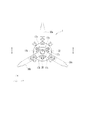
- FIG. 1 is a perspective view of the robot hand 1.
- FIG. 1 shows an X direction, a Y direction and a Z direction which are orthogonal to each other.
- the robot hand 1 includes a motor 3, a bracket 10, an attachment 20, and claw members 30a to 30c.
- the motor 3 is a drive source for opening and closing the claw members 30a to 30c, and is, for example, a stepping motor, but is not limited to this. In FIG. 1, the illustration of the motor 3 is simplified.
- the bracket 10 is attached to the tip side of the motor 3.
- the claw members 30a to 30c are swingably held by the bracket 10.
- the claw members 30a to 30c are arranged at equal angular intervals around a central axis A1 parallel to the Z direction.
- the claw members 30a to 30c are the same members, but different reference numerals are attached for convenience of description.
- the attachment 20 is attached to the center of the front end side of the bracket 10.
- the attachment 20 is formed with an opening 22 so that the central axis A1 passes therethrough.
- a camera, an air suction/jetting device, or the like can be mounted in the opening 22, for example.
- FIGS. 2A to 2D are external views of the claw member 30a.
- a cam follower 33 with which a cam 40 described later is engaged is formed in a bifurcated shape.
- a through hole that penetrates in a direction perpendicular to the plane including the direction in which the claw member 30a swings is provided, and the support shaft 35 is fitted into the through hole so as not to slide. I am fit.
- Bearings 38 are attached to both ends of the support shaft 35 protruding from the claw member 30a. With such a mechanism, the claw member 30a is held by the bracket 10 so as to be able to swing within a predetermined range around the swing axis A2.
- the bearing 38 is an example of a shaft holding member.
- FIG. 3 is an enlarged perspective view of the bracket 10.
- the attachment 20 is removed from the bracket 10.
- a slit opening 12 formed of three slits radially extending around the central axis A1 is formed.
- the attachment 20 is attached to the bracket 10 so as to close the slit opening 12.
- the bracket 10 has a holding space 18a for holding the bearing 38 of the claw member 30a so as to be movable in a predetermined range in the Z direction. Similarly, holding spaces 18b and 18c are formed in the claw members 30b and 30c, respectively. Further, the bracket 10 is formed with two screw holes 17a extending in the Z direction so as to sandwich the claw member 30a. Similarly, the bracket 10 is formed with two screw holes 17b so as to sandwich the claw member 30b and two screw holes 17c so as to sandwich the claw member 30c.
- FIG. 4 is an enlarged perspective view of the cam 40.
- the cam 40 is housed in the bracket 10 and includes a base portion 41 and three-dimensional cam portions 43a to 43c.
- the base portion 41 is formed in a disc shape, and an opening 42 is formed at the center thereof.
- the three-dimensional cam portions 43a to 43c are formed so as to stand up from one surface of the base portion 41.
- the three-dimensional cam portion 43a extends in a substantially arc shape so as to extend from the opening 42 side to the outer peripheral side of the base portion 41.
- the bifurcated cam follower 33 of the claw member 30a is engaged so as to sandwich the solid cam portion 43a.
- each of the three-dimensional cam portions 43a to 43c has one end 43a1 to 43c1 located near the opening 42 and the other end 43a2 to 43c2 located near the outer peripheral edge of the base 41.
- the cam follower 33 of the claw member 30a slides between the one end 43a1 and the other end 43a2, whereby the claw member 30a swings.
- the claw members 30b and 30c are identical to the three-dimensional cam portions 43a to 43c.
- the claw members 30a to 30c When the cam followers 33 of the claw members 30a to 30c are engaged at one ends 43a1 to 43c1 of the three-dimensional cam portions 43a to 43c, the claw members 30a to 30c are in an open state, and when the other ends 43a2 to 43c2 are engaged, they are closed. It becomes a state.
- the cam 40 is driven to rotate in a predetermined range about the central axis A1 by the motor 3, and the base portion 41 is provided with a screw hole for fixing to an output member of the motor 3 although not shown. There is.
- FIG. 5 is a front view of the robot hand 1.
- FIG. 6 is a sectional view taken along line AA of FIG.
- the bracket 10 is formed in a substantially cylindrical shape, and the cam 40 is housed in the internal space 14 inside the bracket 10.
- FIG. 7 is an enlarged view of FIG.
- the screwing hole 17 a extends from the front surface of the bracket 10 toward the bearing 38, and the set screw 51 is inserted therein.
- the set screw 51 can move in the direction in which the screw hole 17a extends in accordance with the amount of screw engagement with the screw hole 17a.
- the amount of screwing of the set screw 51 with the screwing hole 17a is adjusted so as to press the bearing 38 toward the cam 40.
- the set screw 51 screwed into the other screw hole 17a which is not shown in FIG.
- the cam follower 33 of the claw member 30 a is brought into close contact with the three-dimensional cam portion 43 a of the cam 40 via the bearing 38 by the set screw 51. Therefore, the rotation of the cam 40 is immediately transmitted to the claw member 30a, and the positional accuracy of the claw member 30a is improved.
- the set screws 51 are also screwed into the screw holes 17b and 17c, and the bearings 38 of the claw members 30b and 30c are pressed to the cam 40 side. This also improves the positional accuracy of the claw members 30b and 30c. Further, the screwing amount of the set screw 51 can be individually adjusted for each of the claw members 30a to 30c. Therefore, for example, the screwing amount of each of the setscrews 51 can be adjusted according to variations in the molding accuracy of the claw members 30a to 30c and variations in the molding accuracy of the three-dimensional cam portions 43a to 43c of the cam 40.
- FIG. 8 is an explanatory diagram of the first modification.
- FIG. 8 corresponds to FIG. 7.
- the set screw 51 is screwed into the screw hole 17a, and the coil spring 53 is arranged in the screw hole 17a between the set screw 51 and the bearing 38.
- the screwing amount of the set screw 51 of the coil spring 53 is adjusted so that the coil spring 53 is compressed between the set screw 51 and the bearing 38.
- the coil spring 53 is an example of a biasing member.
- the claw members 30b and 30c are also pressed toward the cam 40 side by the set screw 51 and the coil spring 53.
- the biasing force of the coil springs 53 differs depending on the compression length of the coil springs 53
- the biasing forces of the coil springs 53 are assumed, although there are some variations in the biasing forces of these coil springs 53. They are included in a predetermined range and can be regarded as substantially the same. Therefore, the claw members 30a to 30c are pressed toward the cam 40 with a substantially uniform force, and the degree of positional accuracy of the claw members 30a to 30c can be made substantially the same.
- FIG. 9 is an explanatory diagram of the second modified example.
- the above-mentioned screw holes 17a to 17c are not formed in the bracket 10a, and neither the set screw 51 nor the coil spring 53 is adopted.
- a thin metal shim plate 55 is inserted between the bearing 38 and the inner side wall of the bracket 10a. As a result, the bearing 38 is pressed toward the cam 40 by the shim plate 55. Even with such a simple configuration, the positional accuracy of the claw member 30a can be improved.
- the thickness of the shim plate 55 may be appropriately set by the operator.
- the support shaft 35 is a separate body from the claw member 30a, but is not limited to this and may be provided integrally with the claw member 30a.
Landscapes
- Engineering & Computer Science (AREA)
- Robotics (AREA)
- Mechanical Engineering (AREA)
- Manipulator (AREA)
Abstract
La présente invention concerne une main de robot comprenant : une came entraînée par une source d'entraînement ; un support dans lequel la came est stockée ; un élément de griffe qui a un galet de came venant en butée contre la came et qui oscille autour d'un arbre prédéterminé en fonction de l'entraînement de la came ; une partie de support d'arbre qui supporte de manière oscillante l'élément de griffe par rapport au support ; un élément de maintien d'arbre qui maintient de manière rotative la partie de support d'arbre et qui est maintenu par le support de façon à être mobile vers le côté came ; et un élément de pression qui presse l'élément de maintien d'arbre contre le côté came de telle sorte que le suiveur de came est pressé vers la came.
Applications Claiming Priority (2)
| Application Number | Priority Date | Filing Date | Title |
|---|---|---|---|
| JP2019-036934 | 2019-02-28 | ||
| JP2019036934A JP6663058B1 (ja) | 2019-02-28 | 2019-02-28 | ロボットハンド |
Publications (1)
| Publication Number | Publication Date |
|---|---|
| WO2020174844A1 true WO2020174844A1 (fr) | 2020-09-03 |
Family
ID=69998132
Family Applications (1)
| Application Number | Title | Priority Date | Filing Date |
|---|---|---|---|
| PCT/JP2019/050144 WO2020174844A1 (fr) | 2019-02-28 | 2019-12-20 | Main de robot |
Country Status (2)
| Country | Link |
|---|---|
| JP (1) | JP6663058B1 (fr) |
| WO (1) | WO2020174844A1 (fr) |
Families Citing this family (1)
| Publication number | Priority date | Publication date | Assignee | Title |
|---|---|---|---|---|
| JP6937418B2 (ja) * | 2019-10-11 | 2021-09-22 | シナノケンシ株式会社 | ロボットハンド |
Citations (5)
| Publication number | Priority date | Publication date | Assignee | Title |
|---|---|---|---|---|
| JPS6334029A (ja) * | 1986-07-23 | 1988-02-13 | Matsushita Electric Ind Co Ltd | 部品の挾持装置 |
| JPS6342567B2 (fr) * | 1980-09-03 | 1988-08-24 | Seisan Nipponsha Kk | |
| JP2004346959A (ja) * | 2003-05-20 | 2004-12-09 | Harmonic Drive Syst Ind Co Ltd | カム式動力伝達機構 |
| JP2008298165A (ja) * | 2007-05-31 | 2008-12-11 | Fukushima Univ | 立体カム機構 |
| WO2011155070A1 (fr) * | 2010-06-11 | 2011-12-15 | 国立大学法人福島大学 | Manipulateur parallèle |
-
2019
- 2019-02-28 JP JP2019036934A patent/JP6663058B1/ja active Active
- 2019-12-20 WO PCT/JP2019/050144 patent/WO2020174844A1/fr active Application Filing
Patent Citations (5)
| Publication number | Priority date | Publication date | Assignee | Title |
|---|---|---|---|---|
| JPS6342567B2 (fr) * | 1980-09-03 | 1988-08-24 | Seisan Nipponsha Kk | |
| JPS6334029A (ja) * | 1986-07-23 | 1988-02-13 | Matsushita Electric Ind Co Ltd | 部品の挾持装置 |
| JP2004346959A (ja) * | 2003-05-20 | 2004-12-09 | Harmonic Drive Syst Ind Co Ltd | カム式動力伝達機構 |
| JP2008298165A (ja) * | 2007-05-31 | 2008-12-11 | Fukushima Univ | 立体カム機構 |
| WO2011155070A1 (fr) * | 2010-06-11 | 2011-12-15 | 国立大学法人福島大学 | Manipulateur parallèle |
Also Published As
| Publication number | Publication date |
|---|---|
| JP2020138290A (ja) | 2020-09-03 |
| JP6663058B1 (ja) | 2020-03-11 |
Similar Documents
| Publication | Publication Date | Title |
|---|---|---|
| WO2018084312A1 (fr) | Dispositif d'entraînement linéaire, moteur et procédé de production de dispositif d'entraînement linéaire | |
| US20130221594A1 (en) | Clamping mechanism | |
| JPWO2014168042A1 (ja) | 開閉装置 | |
| WO2020174844A1 (fr) | Main de robot | |
| US7073833B2 (en) | Gripper | |
| JP6339750B1 (ja) | 角度調節工具 | |
| JP5250664B2 (ja) | 装着ストロークを可変調節可能な装着器 | |
| JP3851558B2 (ja) | ラックピニオン式パワーステアリング装置 | |
| JP2012030307A (ja) | クランプ装置 | |
| WO2017159297A1 (fr) | Mécanisme de came à plateau et dispositif de serrage comportant un mécanisme de came à plateau | |
| CN110268360A (zh) | 摇轮遥控器阻尼结构和摇轮遥控器 | |
| JP6937418B2 (ja) | ロボットハンド | |
| JP2002059294A (ja) | クランプ装置 | |
| JP6470162B2 (ja) | 安全スイッチ用アクチュエータ | |
| JP4537299B2 (ja) | バックフォーカス調整機構 | |
| JP5336919B2 (ja) | レンズ鏡筒 | |
| JP5453589B2 (ja) | シリンダ装置 | |
| JPH0632520Y2 (ja) | ラックピニオン装置 | |
| CN109702525B (zh) | 固定装置 | |
| WO2020105555A1 (fr) | Dispositif d'entraînement | |
| JP2023019287A (ja) | トルクレンチ | |
| JP2022067650A (ja) | 可動式グリッパ工具 | |
| JP5573552B2 (ja) | パンチピンの角度調整装置及びパンチングマシン | |
| JP4424281B2 (ja) | プリンタ | |
| JP5332026B2 (ja) | 回転運動を直線運動に変える運動機構 |
Legal Events
| Date | Code | Title | Description |
|---|---|---|---|
| 121 | Ep: the epo has been informed by wipo that ep was designated in this application |
Ref document number: 19916931 Country of ref document: EP Kind code of ref document: A1 |
|
| NENP | Non-entry into the national phase |
Ref country code: DE |
|
| 122 | Ep: pct application non-entry in european phase |
Ref document number: 19916931 Country of ref document: EP Kind code of ref document: A1 |