WO2020174704A1 - Structure, robot de transport et conteneur - Google Patents
Structure, robot de transport et conteneur Download PDFInfo
- Publication number
- WO2020174704A1 WO2020174704A1 PCT/JP2019/018127 JP2019018127W WO2020174704A1 WO 2020174704 A1 WO2020174704 A1 WO 2020174704A1 JP 2019018127 W JP2019018127 W JP 2019018127W WO 2020174704 A1 WO2020174704 A1 WO 2020174704A1
- Authority
- WO
- WIPO (PCT)
- Prior art keywords
- container
- unit
- support
- containers
- release
- Prior art date
Links
- 230000009471 action Effects 0.000 claims description 64
- 230000003028 elevating effect Effects 0.000 claims description 44
- 238000001514 detection method Methods 0.000 claims description 28
- NJPPVKZQTLUDBO-UHFFFAOYSA-N novaluron Chemical compound C1=C(Cl)C(OC(F)(F)C(OC(F)(F)F)F)=CC=C1NC(=O)NC(=O)C1=C(F)C=CC=C1F NJPPVKZQTLUDBO-UHFFFAOYSA-N 0.000 claims description 14
- 230000032258 transport Effects 0.000 description 118
- 238000003860 storage Methods 0.000 description 49
- 238000000034 method Methods 0.000 description 32
- 238000004891 communication Methods 0.000 description 29
- 230000010365 information processing Effects 0.000 description 17
- 230000005540 biological transmission Effects 0.000 description 8
- 230000007246 mechanism Effects 0.000 description 7
- 239000011159 matrix material Substances 0.000 description 5
- 230000008569 process Effects 0.000 description 5
- 238000003672 processing method Methods 0.000 description 5
- 230000005856 abnormality Effects 0.000 description 4
- 230000006870 function Effects 0.000 description 4
- 230000008859 change Effects 0.000 description 3
- 239000000470 constituent Substances 0.000 description 3
- 230000006872 improvement Effects 0.000 description 3
- 230000004044 response Effects 0.000 description 3
- 230000001174 ascending effect Effects 0.000 description 2
- 230000007423 decrease Effects 0.000 description 2
- 238000009826 distribution Methods 0.000 description 2
- 238000009434 installation Methods 0.000 description 2
- 238000004519 manufacturing process Methods 0.000 description 2
- 238000004364 calculation method Methods 0.000 description 1
- 238000005516 engineering process Methods 0.000 description 1
- 239000000463 material Substances 0.000 description 1
- 238000010248 power generation Methods 0.000 description 1
- 238000003825 pressing Methods 0.000 description 1
- 239000002994 raw material Substances 0.000 description 1
Images


Classifications
-
- B—PERFORMING OPERATIONS; TRANSPORTING
- B65—CONVEYING; PACKING; STORING; HANDLING THIN OR FILAMENTARY MATERIAL
- B65G—TRANSPORT OR STORAGE DEVICES, e.g. CONVEYORS FOR LOADING OR TIPPING, SHOP CONVEYOR SYSTEMS OR PNEUMATIC TUBE CONVEYORS
- B65G1/00—Storing articles, individually or in orderly arrangement, in warehouses or magazines
- B65G1/02—Storage devices
- B65G1/04—Storage devices mechanical
- B65G1/137—Storage devices mechanical with arrangements or automatic control means for selecting which articles are to be removed
- B65G1/1373—Storage devices mechanical with arrangements or automatic control means for selecting which articles are to be removed for fulfilling orders in warehouses
-
- B—PERFORMING OPERATIONS; TRANSPORTING
- B65—CONVEYING; PACKING; STORING; HANDLING THIN OR FILAMENTARY MATERIAL
- B65G—TRANSPORT OR STORAGE DEVICES, e.g. CONVEYORS FOR LOADING OR TIPPING, SHOP CONVEYOR SYSTEMS OR PNEUMATIC TUBE CONVEYORS
- B65G1/00—Storing articles, individually or in orderly arrangement, in warehouses or magazines
- B65G1/02—Storage devices
- B65G1/04—Storage devices mechanical
- B65G1/0471—Storage devices mechanical with access from beneath
-
- B—PERFORMING OPERATIONS; TRANSPORTING
- B65—CONVEYING; PACKING; STORING; HANDLING THIN OR FILAMENTARY MATERIAL
- B65G—TRANSPORT OR STORAGE DEVICES, e.g. CONVEYORS FOR LOADING OR TIPPING, SHOP CONVEYOR SYSTEMS OR PNEUMATIC TUBE CONVEYORS
- B65G1/00—Storing articles, individually or in orderly arrangement, in warehouses or magazines
- B65G1/02—Storage devices
- B65G1/14—Stack holders or separators
-
- B—PERFORMING OPERATIONS; TRANSPORTING
- B65—CONVEYING; PACKING; STORING; HANDLING THIN OR FILAMENTARY MATERIAL
- B65G—TRANSPORT OR STORAGE DEVICES, e.g. CONVEYORS FOR LOADING OR TIPPING, SHOP CONVEYOR SYSTEMS OR PNEUMATIC TUBE CONVEYORS
- B65G57/00—Stacking of articles
- B65G57/30—Stacking of articles by adding to the bottom of the stack
- B65G57/301—Stacking of articles by adding to the bottom of the stack by means of reciprocatory or oscillatory lifting and holding or gripping devices
- B65G57/302—Stacking of articles by adding to the bottom of the stack by means of reciprocatory or oscillatory lifting and holding or gripping devices added articles being lifted to substantially stationary grippers or holders
-
- B—PERFORMING OPERATIONS; TRANSPORTING
- B66—HOISTING; LIFTING; HAULING
- B66F—HOISTING, LIFTING, HAULING OR PUSHING, NOT OTHERWISE PROVIDED FOR, e.g. DEVICES WHICH APPLY A LIFTING OR PUSHING FORCE DIRECTLY TO THE SURFACE OF A LOAD
- B66F9/00—Devices for lifting or lowering bulky or heavy goods for loading or unloading purposes
- B66F9/06—Devices for lifting or lowering bulky or heavy goods for loading or unloading purposes movable, with their loads, on wheels or the like, e.g. fork-lift trucks
- B66F9/063—Automatically guided
-
- G—PHYSICS
- G05—CONTROLLING; REGULATING
- G05D—SYSTEMS FOR CONTROLLING OR REGULATING NON-ELECTRIC VARIABLES
- G05D1/00—Control of position, course or altitude of land, water, air, or space vehicles, e.g. automatic pilot
- G05D1/02—Control of position or course in two dimensions
-
- G—PHYSICS
- G05—CONTROLLING; REGULATING
- G05D—SYSTEMS FOR CONTROLLING OR REGULATING NON-ELECTRIC VARIABLES
- G05D1/00—Control of position, course or altitude of land, water, air, or space vehicles, e.g. automatic pilot
- G05D1/02—Control of position or course in two dimensions
- G05D1/021—Control of position or course in two dimensions specially adapted to land vehicles
- G05D1/0212—Control of position or course in two dimensions specially adapted to land vehicles with means for defining a desired trajectory
Definitions
- the present invention relates to a gantry, a transfer robot, and a container.
- a three-dimensional automated warehouse includes a rack that accommodates a large number of containers and a robot that takes in and out the containers (see, for example, Patent Documents 1 and 2 and Non-Patent Document 1).
- Patent Documents 1 and 2 and Non-Patent Document 1 [Prior Art Document] [Patent Document] [Patent Document 1] JP 2012-116651 A [Patent Document 2] JP 2017-132641 [Non-Patent Document] [Non-patent document 1] Okamura Manufacturing Co., Ltd., "Automatic warehouse type picking system "AutoStore (auto store)" launched in Japan", [Online], [Search on October 5, 2018], Internet ⁇ http:/// www. okamura. co. jp/company/topics/butsuryu/2014/autostore_1. php>
- a gantry In the first aspect of the present invention, a gantry is provided.
- the pedestal is configured to be able to support, for example, a part of a plurality of vertically stacked containers from the side or the bottom.
- the above-mentioned gantry has, for example, a movable support portion that supports one or more containers from the side or the bottom.
- the support unit In the gantry, for example, by moving the support part, (i) the support part supports one or more containers, and the vertical movement of the one or more containers is restricted by the support part, and (ii)
- the support unit has a switching unit that switches between a state in which the support unit does not support one or more containers and the vertical movement of the one or more containers is not limited by the support unit.
- the support may include an action member that applies a force to the container arranged at a predetermined position.
- the switching unit may include an action member drive unit that moves the action member between a limit position that limits the vertical movement of one or more containers and a release position that releases the limit. ..
- the mount may include a plurality of columns.
- the support unit applies a force to a container arranged at a predetermined position among the one or more containers to support the one or more containers, so that the at least one container is at least lowered. Movement in any direction may be restricted and the load of one or more containers may be transferred to multiple struts.
- a gantry In the second aspect of the present invention, a gantry is provided.
- the pedestal supports, for example, a container that stores articles.
- the pedestal includes a plurality of columns, for example.
- the above-described gantry includes, for example, a restriction unit that restricts the container from moving at least downward by applying a force to the container to support the container and transmits the load of the container to the plurality of columns.
- the limiting section has, for example, an action member that applies a force to the container arranged at a predetermined position.
- the above-mentioned limit part has an action member drive part which moves an action member between a limit position which limits movement, and a release position which releases a limit, for example.
- the plurality of columns may have a first column and a second column that are arranged to face each other.
- the restriction section may include a first restriction section that transfers the load of the container to the first support column.
- the limiting section may include a second limiting section that transfers the load of the container to the second support.
- the first limiting portion and the second limiting portion may support the container by applying a force to the container arranged between the operating member of the first limiting portion and the operating member of the second limiting portion. ..
- the action member drive section of the first restriction section may include the first elastic body.
- One end of the first elastic body may be coupled to the first strut.
- the other end of the first elastic body may be coupled to the working member of the first restriction portion.
- the drive part of the 2nd restriction part may include the 2nd elastic body.
- One end of the second elastic body may be coupled to the second support column.
- the other end of the second elastic body may be coupled to the working member of the second restriction portion.
- the first elastic body moves the acting member of the first limiting portion to the limiting position when an external force larger than a predetermined first threshold is not applied to the acting member of the first limiting portion. You can place it.
- the first elastic body may arrange the action member of the first limiting portion at the release position when an external force larger than the first threshold value is applied to the action member of the first limiting portion. ..
- the second elastic body moves the working member of the second limiting portion to the limiting position when an external force larger than a predetermined second threshold is not applied to the working member of the second limiting portion. You can place it.
- the second elastic body may dispose the action member of the second limiting portion at the release position when an external force larger than the second threshold is applied to the action member of the second limiting portion. ..
- the action member drive section of the first restriction section may include the first elastic body.
- One end of the first elastic body may be coupled to the first strut.
- the other end of the first elastic body may be coupled to the working member of the first restriction portion.
- the drive part of the 2nd restriction part may include the 2nd elastic body.
- One end of the second elastic body may be coupled to the second support column.
- the other end of the second elastic body may be coupled to the working member of the second restriction portion.
- the first elastic body moves the action member of the first limiting portion to the limiting position when an external force larger than a predetermined first threshold is applied to the action member of the first limiting portion. You can place it.
- the first elastic body may dispose the action member of the first limiting portion at the release position when an external force larger than the first threshold value is not applied to the action member of the first limiting portion. ..
- the second elastic body moves the action member of the second limiting portion to the limiting position when an external force larger than a predetermined second threshold is applied to the action member of the second limiting portion. You can place it.
- the second elastic body may arrange the action member of the second limiting portion at the release position when an external force larger than the second threshold value is not applied to the action member of the second limiting portion. ..
- a transfer robot In the third aspect of the present invention, a transfer robot is provided.
- the transfer robot described above transfers, for example, a container containing an article between a first position and a second position. At least one of the first position and the second position is, for example, a pedestal capable of supporting one or more containers.
- the above-mentioned gantry applies a force to (i) a single container or (ii) a part of a plurality of vertically stacked containers to move the container at least downward.
- a restriction unit for restricting the above is provided.
- the transport robot described above includes, for example, a mounting unit capable of mounting at least one container.
- the transfer robot includes, for example, an elevating unit that moves the mounting unit in the vertical direction.
- the transport robot described above includes, for example, a release unit that operates the limit unit of the gantry to release the limit.
- the restriction section may include an action member that applies a force to the container arranged at a predetermined position.
- the above-mentioned restriction part may have an action member drive part which moves an action member between the limit position which limits movement, and the release position which releases limit.
- the above-mentioned release part may give force to the action member arranged at (i) a limit position, and may move an action member to a release position.
- the release unit may (ii) apply electric power or power to the action member drive unit to operate the action member drive unit and move the action member arranged at the restricted position to the release position.
- the release unit may transmit a control signal to the action member drive unit (iii) to activate the action member drive unit and move the action member arranged in the restricted position to the release position.
- the above transfer robot may include a position estimation unit that estimates the position of the transfer robot.
- the transfer robot may include a detection unit that detects a load applied to the mounting unit or a movement amount of the mounting unit.
- the transfer robot may include an elevation controller that controls the operation of the elevation unit.
- the transfer robot may include a release control unit that controls the operation of the release unit.
- the lift control unit controls the lift unit to move the mounting unit upward. Good.
- the lifting control unit may control the lifting unit and continue moving the mounting unit upward.
- the elevating control unit may control the elevating unit and stop the upward movement of the mounting unit when the load or the amount of movement detected by the detection unit satisfies a third condition that is set in advance.
- the release control unit may control the release unit to release the restriction when the load or the movement amount detected by the detection unit satisfies the second condition.
- the release control unit may control the release unit to restore the restriction when the load or the movement amount detected by the detection unit satisfies the third condition.
- the above transfer robot may include a position estimation unit that estimates the position of the transfer robot.
- the transfer robot may include a detection unit that detects a load applied to the mounting unit or a movement amount of the mounting unit.
- the transfer robot may include an elevation controller that controls the operation of the elevation unit.
- the transfer robot may include a release control unit that controls the operation of the release unit.
- the lift control unit controls the lift unit to move the mounting unit upward.
- the elevating control unit may control the elevating unit to move the mounting unit downward when the load or the movement amount detected by the detection unit satisfies a predetermined fifth condition. ..
- the release control unit may control the release unit to release the restriction when the load or the movement amount detected by the detection unit satisfies the fifth condition. In the above transfer robot, the release control unit may control the release unit to restore the restriction when the load or the amount of movement detected by the detection unit satisfies a predetermined sixth condition.
- a container in the fourth aspect of the present invention, stores, for example, an article.
- the container described above includes, for example, a bottom plate on which an article is placed.
- the container described above includes, for example, a side wall whose one end is in contact with the outer edge of the bottom plate and which extends toward one surface of the bottom plate.
- the other end of the side wall has an inclined portion that is inclined with respect to the normal direction of the bottom plate.
- the bottom plate has a convex portion that projects to the side of the other surface of the bottom plate.
- the outer edge portion of the convex portion is inclined with respect to the normal direction of one surface of the bottom plate.
- the absolute value of the difference between the angle formed by the inclined portion of the side wall with respect to the normal direction of the bottom plate and the angle formed by the outer edge portion of the convex portion with respect to the normal direction of the bottom plate is predetermined. Less than the given value.
- An example of the inside of the automated warehouse 100 is schematically shown.
- 1 schematically shows an example of the system configuration of the automated warehouse 100.
- An example of the rack 130 is shown schematically.
- An example of the carrier vehicle 140 is schematically shown.
- 1 schematically shows an example of the structure of the container 120.
- 1 schematically shows an example of the structure of the rack 130.
- 1 schematically shows an example of the structure of the rack 130.
- An example of the cross-sectional shape of the support member 842 is schematically shown.
- 1 schematically shows an example of the structure of a carrier vehicle 140.
- An example of the internal configuration of the control unit 930 is schematically shown.
- An example of information processing in the control unit 930 is schematically shown.
- An example of information processing in the control unit 930 is schematically shown.
- An example of information processing in the control unit 930 is schematically shown.
- 1 schematically shows an example of the internal configuration of the management server 160.
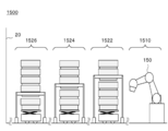
- the other example of the system configuration of the automatic warehouse 1500 is schematically shown.
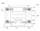
- An example of the structure of the rack 1630 is schematically shown.
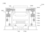
- An example of the structure of the rack 1730 is schematically shown.
- 1 schematically shows an example of the structure of a container 1820.
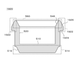
- 1 schematically shows an example of the structure of the container 1920.
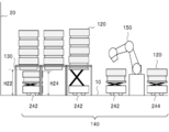
- FIG. 1 schematically shows an example of the inside of the automated warehouse 100.
- FIG. 2 schematically shows an example of the system configuration of the automated warehouse 100.
- the automated warehouse 100 includes one or more containers 120, one or more racks 130, and one or more transport vehicles 140.
- the automated warehouse 100 may include one or more picking devices 150.
- the automated warehouse 100 may include a management server 160.
- the transport vehicle 140 includes a transport vehicle 242 that transports the container 120 between the rack 130 and the picking device 150, and another location inside or outside the automated warehouse 100 from the picking device 150.
- the transport vehicle 242 and the transport vehicle 244 may have the same configuration or different configurations.
- the automated warehouse 100 may be an example of a storage system.
- the container 120 may be an example of the first container, the second container, or the third container.
- the rack 130 may be an example of a pedestal.
- the transport vehicle 140 may be an example of a transport robot.
- the management server 160 may be an example of an operation management unit.
- the transport vehicle 242 may be an example of a transport robot.
- the transport vehicle 244 may be an example of a transport robot.
- the container 120 may be an example of a plurality of containers stacked in the vertical direction.
- the term “one or more” means “one or more”.
- Upward includes not only the case where the direction is upward in the vertical direction but also the case where the angle formed by the direction and the vertical direction is less than 90 degrees.
- the angle between the direction and the vertical direction may be 60 degrees or less, 45 degrees or less, or 30 degrees or less.
- Downward includes not only the case where the direction is downward in the vertical direction but also the case where the angle formed by the direction and the vertical direction is less than 90 degrees.
- the angle between the direction and the vertical direction may be 60 degrees or less, 45 degrees or less, or 30 degrees or less.
- the automated warehouse 100 stores one or more articles.
- Each of the one or more articles is stored, for example, in a state of being housed in the container 120.
- a plurality of containers 120 that are stacked in the vertical direction and stored in a specific rack 130 are arranged above the containers 120 that are stored in the specific rack 130 earlier.
- the containers 120 arranged below are stored so that they can be extracted first from the specific rack 130.
- the container 120 may be moved between the plurality of racks 130. Therefore, among the plurality of containers 120 stacked in a row in the vertical direction and stored in a specific rack 130, the container 120 that was loaded into the automated warehouse 100 earlier in time is not necessarily later in time. It should be noted that they are not placed above the containers 120 that have been stored in.
- a plurality of racks 130 are installed in a matrix on the floor 10 of the automated warehouse 100.
- Each of the plurality of racks 130 supports a plurality of containers 120 stacked in a row.
- Each of the plurality of racks 130 is configured to be able to support, for example, a part of the plurality of vertically stacked containers 120 from the side or the bottom.
- the rack 130 is configured to support a single container 120 included in a plurality of vertically stacked containers 120 from the side or the bottom.
- the rack 130 is configured to support at least two containers 120 included in the plurality of vertically stacked containers 120 from the side or the bottom.
- the rack 130 may support the plurality of containers 120 described above by applying a force to the side surface of some of the containers 120 described above.
- the rack 130 may support the plurality of containers 120 by exerting a force on the lower surface of the part of the containers 120.
- the rack 130 may support the plurality of containers 120 by applying a force to the side surface and the lower surface of some of the containers 120 described above.
- each of the plurality of racks 130 supports the container 120 arranged at the bottom among the plurality of containers 120 stacked in a row.
- the other container 120 is stacked on the one container 120.
- a space is formed below each of the plurality of racks 130.
- the distance H22 between the floor 10 and the lower surface of the container 120 arranged at the bottom among the one or more containers 120 supported by the rack 130 is at least one of the floor 10 and the at least one container 120 mounted on the transport vehicle 140. It is larger than the distance H24 with the upper surface of the container 120 arranged at the top among the containers 120.
- the transport vehicle 140 can freely travel under the plurality of racks 130 arranged in a matrix and transport the container 120 between one position and the other position.
- the transport vehicle 242 transports at least one container 120 between the rack 130 and the picking device 150.
- the transport vehicle 242 may transport at least one container 120 between one rack 130 and another rack 130.
- the one position may be an example of one of the first position and the second position.
- the other position may be an example of the other of the first position and the second position.
- a grid-like travel route is formed under the plurality of racks 130 arranged in a matrix.
- the shape of the travel route is not limited to this embodiment.
- a line-shaped traveling path may be formed under the plurality of racks 130 arranged in a row, and a line-shaped traveling path may be formed under the plurality of racks 130 arranged in a matrix.
- a plurality of paths may be formed.
- the carrier vehicle 242 can move the container 120 in the vertical direction.
- the transport vehicle 242 maintains the container 120 at a relatively low position (sometimes referred to as a travel position) when traveling under the rack 130.
- the transport vehicle 242 moves the container 120 up and down when loading the container 120 into the rack 130 or removing the container 120 from the rack 130.
- the carrier 242 loads the container 120 on the rack 130 according to the following procedure.
- the number of containers 120 loaded in a single rack 130 at one time may be one, or may be two or more.
- the rack 130 supports one or more containers 120, and among the at least one container 120 mounted on the transport vehicle 140, the rack 130 is a single container.
- An example of a procedure for loading the container 120 into the rack 130 will be described by taking the case where the container 120 is newly loaded into the rack 130 as an example.
- the transport vehicle 242 enters below the target rack 130.
- the transport vehicle 242 adjusts the position of the transport vehicle 242.
- the transport vehicle 242 is mounted on the transport vehicle 242 together with the container 120 (which may be referred to as a container A) located at the bottom among the one or more containers 120 supported by the rack 130.
- the position of the carrier 242 is finely adjusted so that the horizontal position of the uppermost container 120 (may be referred to as a container B) of at least one of the existing containers 120 matches.
- the transport vehicle 242 moves the container 120 mounted on the transport vehicle 242 upward to bring the container A and the container B into contact with each other.
- the carrier 242 moves the container 120 mounted on the carrier 242 further upward.
- the bottom of the container A is fitted into the opening of the container B.
- at least one container 120 supported by the rack 130 and at least one container 120 mounted on the transport vehicle 242 simultaneously move upward.
- the transport vehicle 242 stops the movement of the container 120.
- the rack 130 applies a force to the container B to support the container B.
- the transport vehicle 242 lowers the remaining containers 120 to the traveling position.
- the container B is loaded on the rack 130, and the number of containers 120 supported by the rack 130 increases.
- the uppermost container 120 is newly loaded in the rack 130, and the container 120 is loaded in the rack 130 as an example.
- the details of the procedure described were explained.
- the procedure for loading the containers 120 into the rack 130 is not limited to this embodiment.
- a plurality of upper containers 120 may be newly loaded on the rack 130.
- the transport vehicle 242 is a transport vehicle until the container 120 (which may be referred to as a container BX) located at the bottom of the plurality of newly loaded containers 120 is placed at a predetermined position.
- the container 120 mounted on 242 is raised.
- the rack 130 applies a force to the container 120 located at the bottom of the plurality of newly loaded containers 120 to support the container 120.
- the container A may be an example of the first container.
- the container B may be an example of the second container.
- the container BX may be an example of the second container.
- the carrier 242 takes out the container 120 from the rack 130 according to the following procedure.
- the number of the containers 120 taken out from the single rack 130 at one time may be one, or may be two or more.
- the transport vehicle 140 may already be loaded with another container 120, or may not be loaded with another container 120.
- a single container 120 among the one or more containers 120 supported by the rack 130 is used by using the carrier vehicle 140 in which the container 120 is not mounted. An example of the procedure for removing the container 120 from the rack 130 will be described with reference to the case where the container 120 is extracted.
- the carrier 242 enters below the target rack 130.
- the transport vehicle 242 adjusts the position of the transport vehicle 242.
- the transport vehicle 242 includes a container 120 (which may be referred to as a container A) located at the bottom of one or more containers 120 supported by the rack 130, and a mounting surface of the transport vehicle 242. The position of the transport vehicle 242 is finely adjusted so that the positions in the horizontal direction coincide with.
- the carrier 242 raises the mounting surface of the carrier 242 until the mounting surface of the carrier 242 supports the container A.
- the rack 130 also applies a force to the container A to support the container A. Therefore, in this state, even if the mounting surface is lowered, the container A does not move downward. Therefore, after the mounting surface of the transport vehicle 242 supports the container A, the rack 130 reduces the force acting on the container A. This allows the one or more containers 120 supported by the rack 130 to move downward.
- the carrier 242 lowers the mounting surface. At this time, as the mounting surface is lowered, the one or more containers 120 supported by the rack 130 are also moved downward. As a result, the container A is taken out from the rack 130, and the number of containers 120 supported by the rack 130 is reduced.
- the one or more containers 120 supported by the rack 130 include the container A and the one or more containers 120 stacked above the container A, the one or more containers stacked above the container A
- the container 120 which may be referred to as a container C
- the transport vehicle 242 stops the lowering of the mounting surface.
- the rack 130 applies a force to the container C to support the container C.
- the transport vehicle 242 lowers the mounting surface to the traveling position. As a result, the container A is taken out from the rack 130, and the number of containers 120 supported by the rack 130 is reduced.
- the rack 130 to the container A is not used.
- the procedure in which the container 120 is removed from the rack 130 for example, when the rack 130 supports the container 120 located at the bottom of the one or more containers 120 stacked above the container A after the removal of the container 120. Details were explained. However, the procedure for removing the container 120 from the rack 130 is not limited to this embodiment.
- the rack 130 may include any one of the one or more containers 120 stacked above the container A (when referred to as a container CX). May be supported). Thereby, the plurality of containers 120 are taken out from the rack 130 at one time.
- the mounting surface of the carrier vehicle 242 may be an example of a mounting portion.
- the container C may be an example of the third container.
- the container CX may be an example of the third container.
- the automated warehouse 100 can stack the containers 120 up to a position exceeding the height of the rack 130. This significantly reduces the size and mass of the rack 130 as compared to the case where the container 120 is housed inside the rack 130. For example, the height of the rack 130 can be suppressed to the height of several containers 120. Further, according to the present embodiment, the transport vehicle 140 can travel under the rack 130 supporting the container 120 while the container 120 is mounted. As a result, it is not necessary to provide a traveling route for the transport vehicle 140 between the two adjacent racks 130. As a result, the storage density of the containers 120 is improved.
- the container 120 houses one or more items.
- the material, shape, and size of the container 120 are determined, for example, in consideration of the storage efficiency of the articles and the ease of handling.
- the shape and size of the container 120 are not particularly limited, but for example, the width is 20 cm to 1 m, the height is 20 cm to 1 m, and the depth is 20 cm to 1 m.
- the rack 130 supports one or more containers 120.
- the rack 130 may support a plurality of containers 120 stacked in a row.
- the rack 130 applies a force to the container 120 located at the bottom of one or more containers 120 to support the container 120 located at the bottom.
- the transport vehicle 140 having the at least one container 120 mounted therein can travel below the container 120 supported by the rack 130.
- one or more containers 120 may be supported.
- the position where the rack 130 exerts a force on the container 120 is set such that the distance H22 described with reference to FIG. 2 is larger than the distance H24.
- the carrier vehicle 140 carries at least one container 120 between one position and another position. In one embodiment, carrier 140 loads containers 120 onto racks 130. In another embodiment, carrier 140 removes container 120 from rack 130.
- the picking device 150 transfers an article between one container 120 and another container 120.
- the picking device 150 takes out the article stored in the container 120 mounted on the transport vehicle 242 and stores the article in the container 120 loaded on the transport vehicle 244.
- the picking device 150 takes out an article stored in the container 120 mounted on the transport vehicle 244 and stores the article in the container 120 loaded on the transport vehicle 242.
- the management server 160 manages the storage status of items.
- the management server 160 may manage each part of the automated warehouse 100.
- the management server 160 manages the state of each part of the automated warehouse 100.
- the management server 160 may manage the operation of each of the one or more guided vehicles 140.
- the management server 160 may manage the operation of each of the one or more racks 130.
- Each unit of the automated warehouse 100 may be realized by hardware, software, or hardware and software. At least a part of each unit of the automated warehouse 100 may be realized by a single server or may be realized by a plurality of servers. At least a part of each unit of the automated warehouse 100 may be realized on a virtual server or a cloud system. At least a part of each unit of the automated warehouse 100 may be realized by a personal computer or a mobile terminal. Examples of the mobile terminal include a mobile phone, a smartphone, a PDA, a tablet, a notebook computer or a laptop computer, a wearable computer, and the like. Each unit of the automated warehouse 100 may store information using a distributed ledger technology such as a block chain or a distributed network.
- a distributed ledger technology such as a block chain or a distributed network.
- the information processing apparatus having the above-described general configuration includes (i) a data processing apparatus having a processor such as CPU and GPU, ROM, RAM, communication interface, etc., and (ii) keyboard, pointing device, touch panel, camera, voice input.
- a data processing apparatus having a processor such as CPU and GPU, ROM, RAM, communication interface, etc.
- keyboard pointing device, touch panel, camera, voice input.
- storage device such as memory, HDD, SSD (external (Including a storage device).
- the data processing device or the storage device may store the program.
- the above program causes the information processing apparatus to execute the operation defined by the program by being executed by the processor.
- the above program may be stored in a non-transitory computer-readable recording medium.
- the above program may be stored in a computer-readable medium such as a CD-ROM, a DVD-ROM, a memory or a hard disk, or may be stored in a storage device connected to a network.
- the above program may be a program for causing a computer to function as the automated warehouse 100 or a part thereof.
- the above program may include a module that defines the operation of each unit of the automated warehouse 100. These programs or modules work on a data processing device, an input device, an output device, a storage device, etc. to cause a computer to function as each part of the automated warehouse 100, or to cause the computer to execute an information processing method in each part of the automated warehouse 100.
- the above program may be installed in a computer forming at least a part of the automated warehouse 100 from a computer-readable medium or a storage device connected to a network. By executing the above program, the computer may function as at least a part of each unit of the automated warehouse 100.
- the information processing described in the above program is a concrete example in which the software associated with the program and the various hardware resources of the automated warehouse 100 or a part thereof cooperate with each other when the program is read by a computer. Functions as a means. Then, the above-mentioned specific means realizes the calculation or processing of information according to the purpose of use of the computer in this embodiment, whereby the automatic warehouse 100 according to the purpose of use is constructed.
- the above program may be a program for causing a computer to execute the information processing method in the automated warehouse 100 or a part thereof.
- the above information processing method may be a method in which at least one of the rack 130 and the transport vehicle 140 loads the container 120 on the rack 130.
- the above information processing method may be a method in which at least one of the rack 130 and the transport vehicle 140 takes out the container 120 from the rack 130.
- the above information processing method may be a method in which the management server 160 controls at least one of the rack 130 and the transport vehicle 140.
- FIG. 3 schematically shows an example of the rack 130.
- the rack 130 includes a rack body 320 and a container support 340.
- the rack body 320 is installed on the floor 10 and bears the load of the container 120.
- a movable container support 340 is arranged inside the container 120.
- the rack body 320 may be an example of a plurality of columns.
- the container support 340 may be an example of a restriction unit.
- the container support 340 may be an example of a movable support unit.
- the container support 340 supports the container 120 and transfers the load of the container 120 to the rack body 320.
- the container support 340 is configured, for example, to support one or more containers 120 from the side or below and to transfer the load of the one or more containers 120 to at least one of the rack body 320 and the floor 10.
- the lower end of the container support 340 is rotatably attached to the rack body 320.
- the container support 340 rotates and the upper end of the container support 340 moves, so that the container support 340 supports the container 120 or releases the container 120.
- the upper end of the container support 340 supports the recess 302 formed on the side surface of the container 120.
- the position and manner in which the container support 340 supports the container 120 are not particularly limited.
- the container support 340 lifts or pushes up the bottom surface of the container 120 and at least one of the irregularities formed on the side surface of the container 120 to apply an upward force to the container 120, Supports the container 120.
- the container support 340 holds or holds the side surface of the container 120 to apply an upward or sideward force to the side surface of the container 120 to support the container 120. Details of the rack 130 will be described later.
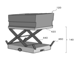
- FIG. 4 schematically shows an example of the carrier vehicle 140.
- the transport vehicle 140 includes a lift table 420, a lift device 440, and a support operation unit 460.
- the lifting table 420 may be an example of a mounting unit.
- the lifting device 440 may be an example of a lifting unit.
- the support operation unit 460 may be an example of a release unit.
- the lifting table 420 is configured to be able to mount at least one container 120. According to the present embodiment, by fitting a part of the bottom of the other container 120 into the opening of the one container 120, the other container 120 is stacked on the one container 120. Therefore, the mounting surface of the lifting table 420 may be formed with a recess into which a part of the bottom of the container 120 is fitted.
- the lifting device 440 moves the lifting table 420 in the vertical direction. Accordingly, the carrier vehicle 140 can move the container 120 mounted on the lifting table 420 upward or downward.
- the support operation unit 460 operates the container support 340 of the rack 130.
- the container support 340 supports the container 120 and releases the container 120.
- the carrier vehicle 140 can load the target container 120 into the target rack 130 or take out the target container 120 from the target rack 130 at an arbitrary timing.
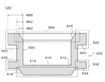
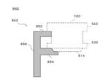
- FIG. 5 schematically shows an example of the structure of the container 120.
- FIG. 5 may be an example of a sectional view when the container 120 is cut along a plane perpendicular to the extending direction of the container 120.
- the container 120 includes a bottom plate 510 and side walls 520.
- the bottom plate 510 is located below the container 120. An article is placed on one surface of the bottom plate 510.
- the bottom plate 510 has a convex portion 514 that projects to the side of the other surface of the bottom plate 510.
- the outer edge portion 516 of the convex portion 514 may be inclined with respect to the normal direction of one surface of the bottom plate 510.
- one end of the side wall 520 is in contact with the outer edge 512 of the bottom plate 510 and extends to one side of the bottom plate 510.
- the other end of the side wall 520 forms an opening 560.
- a space for containing the article is formed inside the container 120.
- the other end of the side wall 520 may have an inclined portion 546 that is inclined with respect to the normal direction of the bottom plate 510.
- the ratio (W52/W54) of the thickness W52 of the inclined portion 546 to the thickness W54 of the side wall 520 is, for example, the accuracy of control of at least one of the position and the attitude of the carrier vehicle 140, the manufacturing accuracy of the rack 130, and the rack 130. It is determined based on at least one of the installation accuracy and the manufacturing accuracy of the container 120.
- the angle formed by the inclined portion 546 with respect to the normal direction of the bottom plate 510 is, for example, the effective mass of the containers 120, the coefficient of friction between the containers 120, the coefficient of friction between the containers 120 and the transport vehicle 140, and the lifting speed of the containers 120. , Is determined based on at least one of the set values of the ascending/descending speed of the container 120.
- the ascending/descending speed of the container 120 may be determined based on the output of an arbitrary sensor such as a force sensor, for example
- the absolute value of the difference between the angle formed by the inclined portion 546 of the side wall 520 with respect to the normal line direction of the bottom plate 510 and the angle formed by the outer edge portion 516 of the protrusion 514 with respect to the normal line direction of the bottom plate 510 is predetermined. May be smaller than the value. As a result, collapse of the containers 120 is suppressed even when a plurality of containers 120 are stacked. Further, since the side wall 520 has the inclined portion 546 and the outer edge portion 516 of the convex portion 514 is inclined, the horizontal position between the one container 120 and the other container 120 may be slightly displaced. However, when the plurality of containers 120 are stacked, the protrusion 514 of the other container 120 is fitted into the opening 560 of the one container 120. As a result, the requirement for the positioning accuracy of the carrier vehicle 140 is reduced, and the loading and unloading efficiency of the containers 120 is improved.
- the convex portion 522 and the convex portion 532 are formed on the outer surface of the side wall 520.
- the recess 302 is formed.
- the container support 340 can support the container 120 by applying a force to at least one of the lower surface 524 of the convex portion 522 and the lower surface 534 of the convex portion 532.
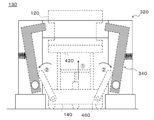
- FIG. 6 schematically shows an example of the structure of the rack 130 in a state where the container support 340 supports the container 120.
- FIG. 7 schematically shows an example of the structure of the rack 130 in a state in which the container support 340 releases the container 120 and the lifting table 420 of the transport vehicle 140 supports the container 120.
- FIG. 6 schematically shows an example of a state in which the container support 340 supports the container 120 and the vertical movement of the container 120 is restricted by the container support 340.
- FIG. 7 schematically illustrates an example of a state in which the container support 340 does not support the container 120 and the vertical movement of the container 120 is not limited by the container support 340.
- the rack 130 includes a rack body 320 and a pair of container supports 340.
- the rack main body 320 has a base portion 622, columns 624, and beams 626.
- the rack main body 320 may include at least a pair of base portions 622, a pair of columns 624, and a beam 626. As shown in FIG. 3, the rack main body 320 may have four base portions 622, four columns 624, and four beams 626.
- each of the pair of container supports 340 may include a support member 642, a mounting member 644, and a spring 646.
- the support member 642 may be an example of an action member and a restriction unit.
- the spring 646 may be an example of a drive unit.
- One of the pair of columns 624 may be an example of one of the first column and the second column.
- the other of the pair of columns 624 may be an example of the other of the first column and the second column.
- One of the pair of container supports 340 may be an example of one of the first limiting portion and the second limiting portion.
- the other of the pair of container supports 340 may be an example of the other of the first limiting section and the second limiting section.
- One of the pair of springs 646 may be an example of one of the first elastic body and the second elastic body.
- the other of the pair of springs 646 may be an example of the other of the first elastic body and the second elastic body.
- the container support 340 may be an example of a movable support unit.
- the spring 646 may be an example of the switching unit.
- the foundation 622 is arranged between the floor 10 on which the rack 130 is installed and at least one of the plurality of columns 624, and supports the at least one column 624.
- the base portion 622 may include a column driving unit (not shown) that moves the column 624 up and down.
- the pillar drive unit may receive a signal from the transport vehicle 140 or the management server 160 and move the pillar 624 up and down. Thereby, the position where the rack 130 supports the container 120 can be adjusted.
- the support column 624 and the beam 626 support the load of the container 120.
- the beam 626 may be disposed, for example, between a pair of columns 624 facing each other, and may connect the pair of columns 624.
- the columns 624 and the beams 626 may be arranged so that the container 120 can move in the vertical direction near the center of the rack body 320.
- the beam 626 is fixed to both the pair of columns 624.
- the beam 626 is not limited to this embodiment.
- the beam 626 may be rotatably attached to one strut 624 and removably attached to the other strut 624.
- a beam driving unit (not shown) that drives the beam 626 may be arranged on one of the columns 624.
- the beam driver may receive a signal from the carrier vehicle 140 or the management server 160 to drive the beam 626.
- the degree of freedom in traveling of the carrier vehicle 140 equipped with a large number of containers 120 is improved.
- the efficiency of loading or unloading the article is improved.
- one end of the support member 642 is rotatably attached to the support column 624 via the attachment member 644.
- the support member 642 may transfer the load of the container 120 to the support column 624 via the attachment member 644.
- the position of the upper surface 652 of the support member 642 changes as the support member 642 rotates about one end. Accordingly, the support member 642 can support the container 120 or release the container 120. As a result, the vertical movement of the container 120 is restricted or the restriction is lifted.
- the support member 642 applies a force to the container 120 arranged at a predetermined position to support the container 120. Accordingly, the support member 642 restricts the container 120 from moving at least downward. On the other hand, when the support member 642 moves, the force acting on the container 120 decreases, the container 120 is released, and the container 120 is allowed to move downward.
- the support member 642 closes at least a part of the movement path of the container 120 mounted on the lift table 420 of the transport vehicle 140. This restricts the container 120 from moving upward. On the other hand, when the support member 642 moves, the movement path of the container 120 is secured, and the container 120 is allowed to move upward.
- the attachment member 644 rotatably attaches one end of the support member 642 to the support column 624.
- the position of the upper surface 652 of the support member 642 may change.
- the load of the container 120 may be transmitted to the support column 624.
- the spring 646 drives the support member 642.
- the spring 646 drives the support member 642 between a limit position where the support member 642 limits the movement of the container 120 and a release position where the support member 642 releases the limit.
- the spring 646 has one end coupled to the inside of the column 624. The other end of spring 646 is coupled to support member 642. Accordingly, the spring 646 can urge the support member 642. According to the present embodiment, the spring 646 biases the support member 642 from the outside of the rack 130 toward the inside.
- the spring 646 arranges the support member 642 at the above-mentioned limit position. To do. At this time, the container 120 is supported by the support member 642.
- the carrier 140 raises the lifting table 420, and the lifting table 420 supports the container 120.
- the transport vehicle 140 pushes the support member 642 from the inside of the rack 130 to the outside using the support operation unit 460.
- the support member 642 rotates around the connection point with the mounting member 644.
- the spring 646 positions the support member 642 in the release position. At this time, the container 120 is released and allowed to move upward or downward.
- adjusting the spring 646 installation position causes the spring 646 to bias the support member 642 from the inside to the outside of the rack 130.
- the spring 646 may arrange the support member 642 in the above-mentioned release position when an external force larger than a predetermined threshold is not applied to the support member 642.
- the spring 646 may arrange the support member 642 in the above-mentioned limit position.
- the spring 646 can switch the state of the rack 130 by moving the container support 340. For example, the spring 646 moves the container support 340 to switch between a state in which the rack 130 supports the container 120 and a state in which the rack 130 does not support the container 120. Further, the spring 646 can switch the state of the container 120 by moving the container support 340. For example, the spring 646 moves the container support 340 to switch between a state in which the movement of the container 120 is restricted by the container support 340 and a state in which the movement of the container 120 is not restricted by the container support 340.
- the means for urging the support member 642 is not limited to the spring 646.
- the spring 646 may be replaced with an elastic body such as rubber.
- balance weights, actuators, cam structures, etc. may be utilized.
- the rack 130 includes the pair of container supports 340.
- the spring constant of the spring 646 of the one container support 340 and the spring constant of the spring 646 of the other container support 340 may be the same or different.
- the above threshold value for the one container support 340 may be an example of one of the first threshold value and the second threshold value.
- the above threshold for the other container support 340 may be an example of the other of the first threshold and the second threshold.
- the position of the container support 340 is changed in response to the conveyance vehicle 140 applying an external force to the support member 642 of the rack 130.
- a spring 646 is installed.
- the method of changing the position of the container support 340 is not limited to this embodiment.
- the position of the container support 340 may change in response to the rack 130 receiving at least one of force, power, power and signals from the carrier 140.
- the signal may be an electric signal or a wireless signal.
- FIG. 8 schematically shows an example of a sectional shape of the support member 842.
- the support member 842 is different from the support member 642 in that it supports not only a part of the protrusion 522 of the container 120 but also a part of the protrusion 532 and a part of the protrusion 514 of the container 120.
- Other configurations of the support member 842 may have the same features as the corresponding configurations of the support member 642.
- the support member 842 includes a support portion 852, a support portion 854, and a connecting portion 856.
- the support portion 852 supports a part of the convex portion 522 of the container 120.
- the support part 854 supports a part of the convex part 532 and a part of the convex part 514 of the container 120.
- the surface shape of the support portion 854 may be configured to match the surface shape of part of the convex portion 532 and part of the convex portion 514.
- the connecting portion 856 connects the supporting portion 852 and the supporting portion 854.
- the connecting portion 856 is rotatably attached to the support column 624 via the attachment member 644 at one end portion.
- the connecting portion 856 is connected to the supporting portion 852 at the other end.
- the connecting portion 856 is coupled to the supporting portion 854 at a position between the one end and the other end.
- the support member 842 may be an example of an action member and a restriction unit.
- the support member 842 may be an example of a movable support unit.
- the support portion 852 may be an example of a movable support portion.
- the support portion 854 may be an example of a movable support portion.
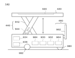
- FIG. 9 schematically shows an example of the structure of the carrier vehicle 140.
- the transport vehicle 140 includes a lift table 420, a lift device 440, a support operation unit 460, a control unit 930, a sensing unit 932, a communication unit 934, a power supply 936, a front wheel 980, and a drive unit.
- a wheel 982 and a motor 984 are provided.
- a recess 920 is formed on the mounting surface of the lifting table 420.
- the lifting device 440 has a pantograph 942 and an actuator 944.
- the support operating section 460 has an operating member 962 and a motor 964.
- the sense unit 932 may be an example of a detection unit.
- control unit 930 controls the operation of the carrier vehicle 140. Details of the control unit 930 will be described later.
- the sense unit 932 includes various sensors.
- the sense unit 932 may include a position sensor for acquiring information indicating the position of the transport vehicle 140.
- the sense unit 932 may include a load sensor that detects a load applied to the lifting table 420.
- the sense unit 932 may include a lift amount sensor that detects the amount of movement of the lift table 420.
- the position sensor As the position sensor, (i) a distance measuring sensor that measures the distance from the wall 20 of the automated warehouse 100, and (ii) information given to a specific position on the floor 10 and acquiring information indicating the position.
- a sensor etc. are illustrated.
- the sensor may be a camera, a magnetic sensor, or a beacon receiver.
- the communication unit 934 transmits/receives information to/from at least one of the rack 130, another transport vehicle 140, the picking device 150, and the management server 160.
- the communication unit 934 may send and receive information to and from the container 120.
- the communication method between the communication unit 934 and another device is not particularly limited.
- the power supply 936 supplies electric power to each part of the carrier vehicle 140.
- the power source 936 may include at least one of a power generation device and a power storage device.
- the front wheels 980 and the drive wheels 982 support the carrier vehicle 140.
- the motor 984 drives the drive wheels 982 to move the transport vehicle 140.
- the convex portion 514 of the container 120 is fitted into the concave portion 920 when the lifting table 420 supports the container 120.
- the surface shape of the recess 920 may be configured to match the surface shape of the protrusion 514.
- the pantograph 942 supports the lifting table 420.
- the actuator 944 drives the pantograph 942 to raise and lower the lift table 420.
- the operation member 962 is driven by the motor 964 to restrict the movement of the container 120 or release the restriction.
- the motor 964 drives the operation member 962.
- one end of the operating member 962 is coupled to the rotation shaft of the motor 964.
- the operation member 962 When the operation member 962 is arranged at the initial position, the other end of the operation member 962 is not in contact with the support member 642 of the container support 340. At this time, the support member 642 supports the container 120, and the vertical movement of the container 120 is restricted.
- the motor 964 rotates the operating member 962
- the other end of the operating member 962 pushes the support member 642 of the container support 340 from the inside of the rack 130 to the outside. This releases the restriction on the movement of the container 120.
- the motor 964 rotates the operation member 962 and the operation member 962 returns to the initial position, the vertical movement of the container 120 is restricted.
- the support operation unit 460 applies a force to the support member 642 disposed at the limit position to move the support member 642 to the release position, and the movement limitation of the container 120 is performed.
- An example of a method of releasing has been described.
- the method of canceling the movement restriction of the container 120 is not limited to this embodiment.
- the support operation unit 460 applies electric power or power to the container support 340 to operate the drive unit that drives the support member 642. Thereby, the support operation part 460 can move the support member 642 arranged at the limit position to the release position.
- the mechanism for applying power to the container support 340 by the support operating unit 460 includes a ball screw, a rotary shaft, a pulley, a belt, a chain, a gear, a gear, a gear, a rack and pinion, a Geneva mechanism, a link mechanism, a crank mechanism, and these. A combination is exemplified.
- the support operation unit 460 sends a control signal to the container support 340 to activate the drive unit that drives the support member 642. Thereby, the support operation part 460 can move the support member 642 arranged at the limit position to the release position.
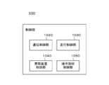
- FIG. 10 schematically shows an example of the internal configuration of the control unit 930.
- the control unit 930 includes a communication control unit 1020, a travel control unit 1030, a lifting device control unit 1040, and an operation member control unit 1050.
- the traveling control unit 1030 may be an example of a position estimation unit.
- the lifting device control unit 1040 may be an example of a lifting control unit and a position estimation unit.
- the operation member control unit 1050 may be an example of a release control unit.
- the communication control unit 1020 controls communication between the carrier vehicle 140 and external devices.
- the communication control unit 1020 may control the operation of the communication unit 934.
- the traveling control unit 1030 controls the movement of the carrier vehicle 140.
- the traveling control unit 1030 acquires the information output by the position sensor included in the sense unit 932.
- the traveling control unit 1030 estimates the position of the carrier vehicle 140 based on the information output by the position sensor.
- the traveling control unit 1030 controls the motor 984 based on the estimated position of the transport vehicle 140 to move the transport vehicle 140 to the destination.
- the lifting device control unit 1040 controls the operation of the lifting device 440.
- the lifting device control unit 1040 acquires information output by the position sensor included in the sense unit 932.
- the lifting device control unit 1040 estimates the position of the transport vehicle 140 based on the information output by the position sensor.
- the lifting device control unit 1040 controls the lifting device 440 to move the lifting table 420 upward.
- the first condition may be a condition that the error between the estimated position of the carrier vehicle 140 and the destination of the carrier vehicle 140 is smaller than a predetermined value.
- the lifting device control unit 1040 acquires the information output by the load sensor or the lifting amount sensor included in the sensing unit 932. When the load applied to the lifting table 420 detected by the load sensor or the movement amount of the lifting table 420 detected by the lifting amount sensor satisfies the second predetermined condition, the lifting device control unit 1040 causes the lifting device controller 1040 to move up and down. The device 440 is controlled to continue moving above the lifting table 420.
- the second condition is, for example, a condition that the load is larger than a predetermined value or a condition that the movement amount is within a predetermined numerical range. Accordingly, the lifting device control unit 1040 can detect contact between the container 120 supported by the rack 130 and the lifting table 420 or the container 120 mounted on the lifting table 420. Further, the lifting device control unit 1040 can detect the timing at which the movement restriction of the container 120 by the rack 130 is released.
- the lifting device control unit 1040 When the load applied to the lifting table 420 detected by the load sensor or the movement amount of the lifting table 420 detected by the lifting amount sensor satisfies the third predetermined condition, the lifting device control unit 1040 causes the lifting device controller 1040 to move up and down.
- the device 440 is controlled to stop the movement above the lifting table 420.
- the third condition include a condition that the load is smaller than a predetermined value and a condition that the movement amount is within a predetermined numerical range.
- the lifting device control unit 1040 can detect the completion of loading or unloading the target containers 120. Further, the lifting device control unit 1040 can detect the timing at which the movement restriction of the container 120 by the rack 130 is restored.
- the lifting device control unit 1040 controls the lifting device 440 to move the lifting table 420 upward.
- the fourth condition may be a condition that the error between the estimated position of the carrier vehicle 140 and the destination of the carrier vehicle 140 is smaller than a predetermined value.
- the lifting device control unit 1040 causes the lifting device controller 1040 to move up and down.
- the device 440 is controlled to move the lifting table 420 downward.
- the lifting/lowering device controller 1040 may control the lifting/lowering device 440 to stop the lifting/lowering of the lifting/lowering table 420 for a certain period before moving the lifting/lowering table 420 downward.
- Examples of the fifth condition include a condition that the load is larger than a predetermined value and a condition that the movement amount is within a predetermined numerical range.
- the lifting device control unit 1040 can detect contact between the container 120 supported by the rack 130 and the lifting table 420 or the container 120 mounted on the lifting table 420. Further, the lifting device control unit 1040 can detect the timing at which the movement restriction of the container 120 by the rack 130 is released.
- the operation member control unit 1050 controls the operation of the support operation unit 460.
- the operation member control unit 1050 acquires information output by the load sensor or the lift amount sensor included in the sense unit 932.
- the operation member control unit 1050 causes the support operation unit to operate.
- the movement restriction of the container 120 may be released by operating 460.
- the operation member control unit 1050 causes the support operation unit to operate.
- the movement restriction of the container 120 may be restored by operating 460.
- the operation member control unit 1050 causes the support operation unit to operate.
- the movement restriction of the container 120 may be released by operating 460.
- the operation member control unit 1050 sets the support.
- the operation unit 460 may be operated to restore the movement restriction of the container 120. Examples of the sixth condition include a condition that the load is within the limit of the weight capacity of the lifting table 420 and a condition that the movement amount is within a predetermined numerical range.
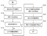
- FIG. 11 schematically shows an example of information processing in the control unit 930.
- FIG. 11 schematically illustrates an example of a method in which the transport vehicle 140 controls the operation of loading the containers 120 into the rack 130.
- the traveling control unit 1030 controls the motor 984 to cause the transport vehicle 140 to enter under the rack 130 that is the destination.
- the transport vehicle 140 has a container 120 to be loaded on the rack 130.
- the elevating device controller 1040 controls the elevating device 440 to start elevating the elevating table 420 after confirming that the transport vehicle 140 has moved to an appropriate position.
- the lifting device control unit 1040 monitors the load applied to the lifting table 420 detected by the load sensor or the movement amount of the lifting table 420 detected by the lifting amount sensor.
- the lifting device control unit 1040 determines whether or not the above-mentioned load or movement amount satisfies a predetermined condition.
- the above conditions may be conditions for detecting contact between the container 120 supported by the rack 130 and the lifting table 420 or the container 120 mounted on the lifting table 420.
- the above condition may be the second condition described above.
- the lifting device control unit 1040 determines that the load or the movement amount satisfies the condition. Is transmitted to the operation member control unit 1050. At this time, the lifting device control unit 1040 may control the lifting device 440 to suspend the lifting of the lifting table 420.
- the operation member control unit 1050 operates the support operation unit 460 to release the movement restriction of the container 120. This allows the container 120 to move further upward.
- step S1132 the lifting device control unit 1040 controls the lifting device 440 to further lift the lifting table 420.
- the lifting device control unit 1040 controls the lifting device 440 to stop the lifting table 420.
- the operation member control unit 1050 operates the support operation unit 460 to restore the movement restriction of the container 120. As a result, the number of containers 120 supported by the rack 130 increases.
- the lifting device control unit 1040 controls the lifting device 440 to lower the lifting table 420 to the traveling position. This completes the loading operation of the containers 120.
- FIG. 12 schematically shows an example of information processing in the control unit 930.
- FIG. 12 schematically shows an example of a method in which the transport vehicle 140 controls the operation of removing the container 120 from the rack 130. 12, steps similar to those in FIG. 11 are designated by the same reference numerals as those in FIG. 11, and description thereof is omitted.
- the lifting device control unit 1040 controls the lifting device 440 to lower the lifting table 420.
- the lifting device control unit 1040 controls the lifting device 440 to stop the lifting table 420.
- the operation member control unit 1050 operates the support operation unit 460 to restore the movement restriction of the container 120. As a result, a desired number of containers 120 are taken out from the rack 130, and the number of containers 120 supported by the rack 130 is reduced.
- the lifting device control unit 1040 controls the lifting device 440 to lower the lifting table 420 to the traveling position. This completes the work of taking out the container 120.
- FIG. 13 schematically shows an example of information processing in the control unit 930.
- FIG. 13 schematically illustrates an example of a method in which the transport vehicle 140 controls the operation of removing the container 120 from the rack 130.
- the details of the take-out work will be described by exemplifying a case where the container 120 targeted for the take-out work is not the container 120 located at the bottom of the plurality of containers 120 supported by the rack 130.
- step S1320 the control unit 930 controls the transport vehicle 140 to move the transport vehicle 140 below the destination rack AA.
- control unit 930 controls the transport vehicle 140 by the procedure similar to that described with reference to FIG. 12, and takes out the container X from the rack LA. Further, the control unit 930 controls the transport vehicle 140 to cause the transport vehicle 140 to enter under the rack LB different from the rack LA. The control unit 930 controls the transport vehicle 140 by the same procedure as that described with reference to FIG. 11 to load the container X into the rack LB.
- control unit 930 controls the transport vehicle 140 to cause the transport vehicle 140 to enter under the rack LA again.
- the control unit 930 controls the transport vehicle 140 to take out the container Y from the rack LA by a procedure similar to the procedure described with reference to FIG. This completes the work of taking out the container 120.
- the details of the work of taking out the container 120 have been described by taking the case where one transport vehicle 140 performs all the work as an example.
- the operation of taking out the container 120 is not limited to this embodiment.
- a plurality of vehicles 140 may cooperate to carry out the operation of taking out the container 120.
- the transport vehicle VA takes out the container X from the rack LA and loads the container X on the rack LB.
- the transport vehicle VB takes out the container X from the rack LA.
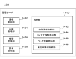
- FIG. 14 schematically shows an example of the internal configuration of the management server 160.
- the management server 160 includes a communication control unit 1422, an inventory management unit 1424, a device management unit 1426, a request reception unit 1428, and a storage unit 1440.
- the storage unit 1440 has an article information storage unit 1442, a container information storage unit 1444, a rack information storage unit 1446, and a guided vehicle information storage unit 1448.
- the communication control unit 1422 controls communication between the management server 160 and at least one of the container 120, the rack 130, the transport vehicle 140, and the picking device 150.
- the communication control unit 1422 may control communication between the management server 160 and the user's communication terminal (not shown).
- the communication method is not particularly limited.
- the inventory management unit 1424 manages the inventory status of the automated warehouse 100. Thereby, the management server 160 can appropriately store the article. Specifically, the inventory management unit 1424 manages the information for identifying each of the plurality of items and the information for identifying the container in which the item is stored in association with each other.
- the inventory management unit 1424 includes information that identifies each of the plurality of containers 120, information that identifies the rack 130 in which the containers are loaded, and information that indicates in which stage of the rack the relevant containers are arranged. Are managed in association with each other.
- the device management unit 1426 manages at least one of the container 120, the rack 130, the transport vehicle 140, and the picking device 150.
- the device management unit 1426 may manage at least one state of the container 120, the rack 130, the transport vehicle 140, and the picking device 150.
- the device management unit 1426 may control the operation of at least one of the container 120, the rack 130, the transport vehicle 140, and the picking device 150.
- the device management unit 1426 allocates the transfer work to each of the one or more transfer vehicles 140. More specifically, the device management unit 1426 transmits, to the transport vehicle 140, information indicating the position of the container 120 that is the target of the transport work and the position of the transport destination. The device management unit 1426 may transmit information indicating the travel route of the transport vehicle 140 to the transport vehicle 140.
- the request receiving unit 1428 receives various requests from at least one of the container 120, the rack 130, the transport vehicle 140, the picking device 150, and the user's communication terminal.
- the request receiving unit 1428 may process the above request. For example, the request receiving unit 1428 receives, from each device, information indicating an abnormality of itself or another device and information requesting that the abnormality be dealt with.
- the storage unit 1440 stores various information used for information processing in the management server 160.
- the item information storage unit 1442 stores the information for identifying each of the plurality of items and the information for identifying the container in which the item is stored in association with each other.
- the article information storage unit 1442 may store the information for identifying each of the plurality of articles and the information indicating the specifications of the article in association with each other. Examples of the information indicating the specifications of the article include size, shape, mass, raw material, expiration date, expiration date, expiration date, price, and the like.
- the article information storage unit 1442 may store the information for identifying each of the plurality of articles and the information regarding the physical distribution of the article in association with each other. Examples of the information regarding the physical distribution of the goods include an elapsed time after the goods are stored in the automated warehouse 100, an average residence time of the same kind of goods, and the like.
- the container information storage unit 1444 stores information that identifies each of the plurality of containers 120 and information that identifies the rack in which the containers are loaded, in association with each other.
- the container information storage unit 1444 includes information for identifying each of the plurality of containers 120, information for identifying the rack 130 in which the container is loaded, and information indicating in which stage of the rack the container is arranged. And may be stored in association with each other.
- the rack information storage unit 1446 stores information that identifies each of the plurality of racks 130, information that indicates the position of the rack, and information that indicates the current status of the rack in association with each other.
- Examples of the current status of the rack 130 include the number of containers 120 loaded in the rack, the number of containers 120 that can be further loaded in the rack, the presence/absence of an abnormality, and the driving status of each drive unit. ..
- the carrier information storage unit 1448 stores the information for identifying each of the plurality of 140 and the information indicating the current status of the carrier in association with each other.
- the current status of the carrier vehicle 140 includes the presence or absence of the carrier work assigned to the carrier vehicle, the content of the carrier work, the current position of the carrier vehicle, the number of containers 120 mounted on the carrier vehicle, the carrier vehicle. Examples of the number of containers 120 that can be further mounted on the disk, whether or not an abnormality has occurred, the driving status of each driving unit, and the like are illustrated.
- FIG. 15 schematically shows another example of the system configuration of the automated warehouse 1500.
- the automated warehouse 1500 is different from the automated warehouse 100 described with reference to FIGS. 1 to 14 in that the automated warehouse 1500 includes a plurality of racks 130 that support the containers 120 at different positions.
- the automated warehouse 1500 in FIG. 15 may have the same features as the automated warehouse 100 in FIGS. 1 to 14.
- the inside of the automated warehouse 1500 is divided into an area 1510, an area 1522, an area 1524, and an area 1526.
- a picking device 150 is arranged in the area 1510.
- Area 1522 is the area closest to area 1510
- area 1526 is the area farthest from area 1510.
- the position where each of the one or more racks 130 arranged in the area 1522 supports the container 120 is higher than the position where each of the one or more racks 130 arranged in the area 1524 supports the container 120. Set to position.
- the racks 130 arranged in the area 1522 more containers 120 are loaded and unloaded at one time than when the racks 130 arranged in the area 1524 are used. be able to.
- the position where each of the one or more racks 130 arranged in the area 1524 supports the container 120 is higher than the position where each of the one or more racks 130 arranged in the area 1526 supports the container 120. Set to position.
- the racks 130 arranged in the area 1524 more containers 120 are loaded and unloaded at one time than when the racks 130 arranged in the area 1526 are used. be able to.
- FIG. 16 schematically shows an example of the structure of the rack 1630.
- the spring 646 biases the support member 642 from the outside to the inside of the rack 130, so that the support member 642 is moved.
- An example is a case where the support member 642 is arranged at the restriction position, and (ii) the support operation unit 460 of the transport vehicle 140 pushes the support member 642 from the inside to the outside of the rack 130 to place the support member 642 at the release position.
- the details of the rack 130 are described.
- the rack 1630 is different from the rack 130 in that the rack 1630 has a drive mechanism that drives a support member that supports the container 120, and power for operating the drive mechanism is supplied from the transport vehicle 140. To do. With respect to offensives other than the above differences, the rack 1630 may have similar characteristics to the rack 130.
- the rack 1630 includes a rack body 320 and a container support 1640.
- the container support 1640 has a support member 1642, an actuator 1644, a power receiving portion 1646, and a power transmission portion 1650.
- the power transmission unit 1650 includes a pulley 1652, a belt 1654, and a pulley 1656.
- the carrier vehicle 140 includes a support operation unit 1660.
- the support operating unit 1660 supplies power to the power receiving unit 1646 by applying pressure or applying rotational force to the power receiving unit 1646.
- the support operation unit 1660 can move the support member 1642 from the limit position to the release position or move the support member 1642 from the release position to the control position by adjusting the power supply mode, for example.
- the support operation unit 1660 may be housed in an appropriate position inside or outside the transport vehicle 140 when the transport vehicle 140 is traveling.
- the support operation unit 1660 may move to a position where power can be supplied to the power receiving unit 1646 after entering under the target rack 130.
- the support member 1642 may be an example of an action member and a restriction unit.
- the actuator 1644 may be an example of a drive unit.
- the container support 1640 may be an example of the first restriction unit or the second restriction unit.
- the support operation unit 1660 may be an example of a release unit.
- the support member 1642 applies a force to the container 120 arranged at a predetermined position to support the container 120.
- one end of the support member 1642 is connected to the actuator 1644.
- the other end of the support member 1642 is used to support the container 12.
- the actuator 1644 drives the support member 1642.
- the actuator 1644 drives the support member 1642 between a limit position where the support member 1642 limits the movement of the container 120 and a release position where the support member 1642 releases the limit.
- the power reception unit 1646 receives power from the support operation unit 1660 of the carrier vehicle 140.
- the power transmission unit 1650 transmits the power received by the power reception unit 1646 from the support operation unit 1660 to the actuator 1644. Accordingly, the actuator 1644 can move the support member 1642 from the limit position to the release position, or move the support member 1642 from the release position to the control position.
- the mechanical elements forming the power transmission unit 1650 are not limited to the present embodiment.
- FIG. 17 schematically shows an example of the structure of the rack 1730.
- the rack 1730 has a drive mechanism that drives a support member that supports the container 120, and a control signal for driving the support member between the limit position and the drive position is supplied from the transport vehicle 140. It is different from the rack 130 or the rack 1630 in that Regarding configurations other than the above differences, the rack 1730 may have the same characteristics as the rack 130 or the rack 1630.
- the rack 1730 includes a rack body 320 and a container support 1740.
- the container support 1740 includes a support member 1642, an actuator 1644, a reception unit 1742, a communication cable 1744, a motor 1752, a power transmission unit 1754, a power supply 1756, and a power cable 1758.
- the carrier vehicle 140 includes a support operation unit 1760.
- the support operation unit 1760 transmits a control signal for driving the support member between the limit position and the drive position.
- the container support 1740 may be an example of the first restriction unit or the second restriction unit.
- the support operation unit 1760 may be an example of a release unit.
- the receiving unit 1742 receives the control signal transmitted by the support operating unit 1760. Communication between the receiving unit 1742 and the support operation unit 1760 may be wired communication or wireless communication. Upon receiving the control signal, the receiving unit 1742 transmits the control signal to the motor 1752 via the communication cable 1744.
- the motor 1752 supplies power to the actuator 1644 via the power transmission unit 1754.
- the motor 1752 operates the actuator 1644 according to the control signal received by the receiving unit 1742. Accordingly, the actuator 1644 can move the support member 1642 from the limit position to the release position, or move the support member 1642 from the release position to the control position.
- the power supply 1756 supplies electric power to the motor 1752 via the electric power cable 1758.
- the details of the container support 1740 have been described by taking the case where the container support 1740 has the power supply 1756 as an example.
- the container support 1740 is not limited to this embodiment. In other embodiments, the container support 1740 may not have the power supply 1756.
- the support operation unit 1760 may supply power to the motor 1752 via the power cable 1758.
- FIG. 18 schematically shows an example of the structure of the container 1820.
- each rack includes a support member for supporting the container 120 and a drive unit that drives the support member.
- the container 1820 is related to FIGS. 1 to 17 in that a support member for supporting a container 120 by a rack and a driving unit for driving the support member are arranged in the container 120.
- the container 1820 may have the same characteristics as the container 120.
- the container 1820 includes a support member 1842, an actuator 1844, and a power receiving section 1846.
- the support member 1842, the actuator 1844, and the power receiving portion 1846 are arranged on the bottom plate 510.
- support member 1842 may be disposed on a portion of sidewall 520.
- one end of the support member 1842 is connected to the actuator 1844.
- the support member 1842 moves between a restricted position in which the other end of the support member 1842 projects outside the side wall 520 and a release position in which the other end of the support member 1842 is located inside the side wall 520. ..
- the support member 1842 is supported by the beam 626 of the rack 130, for example.
- the actuator 1844 drives the support member 1842.
- the actuator 1844 drives the support member 1842 between the restricted position and the release position.
- the power receiving unit 1846 receives power from the carrier vehicle 140 described with reference to FIG. 16 via the support operation unit 1660, for example.
- the power reception unit 1846 transmits the power received from the support operation unit 1660 to the actuator 1844.
- the details of the container 1820 have been described by taking the case where the actuator 1844 drives the support member 1842 using the power supplied from the transport vehicle 140 as an example.
- the method of driving the support member 1842 is not limited to this embodiment.
- the carrier vehicle 140 may drive the support member 1842 by directly applying a mechanical force to the support member 1842.
- the carrier 140 may supply electric power to drive the actuator 1844, and the actuator 1844 may use the electric power supplied from the carrier 140 to drive the support member 1842.
- the container 1820 may have a power source and the actuator 1844 may drive the support member 1842 based on a control signal supplied from the transport vehicle 140 to drive the support member 1842.
- FIG. 19 schematically shows an example of the structure of the container 1920.
- the support operation unit 460 moves the container support 340 to the release position and then the container 120 is removed. After being raised and the container 120 was raised to an appropriate position, the container support 340 was moved to the restricted position.
- the transport vehicle 140 can load the container 1920 on the rack 130 without moving the container support 340 to the release position.
- the container 1920 differs from the container 120 in that a convex portion 1922 is formed on the outer surface of the side wall 520. Regarding configurations other than the above differences, the container 1920 may have the same characteristics as the container 120.
- the convex portion 1922 has a lower surface 1924 and an inclined portion 1926.
- the inclined portion 1926 is formed in a region outside the upper end of the convex portion 1922.
- the inclined portion 1926 is inclined so that the closer to the upper end of the side wall 520, the smaller the amount of protrusion of the side wall 520 to the outside.
- the inclined portion 1926 is formed at the upper end of the side wall 520
- the container 1920 mounted on the lifting table 420 causes the container support 340 to move toward the container support 340. Ascend while pushing open.
- the transport vehicle 140 may stop the lifting of the lifting table 420.
- the transport vehicle 140 lowers the lifting table 420, the lower surface 1924 of the convex portion 1922 is supported by the container support 340. Accordingly, the carrier vehicle 140 can load the containers 1920 into the rack 130 without moving the container support 340 to the release position.
- [Item A] It is equipped with a gantry that can support a part of a plurality of vertically stacked containers from the side or from below, The plurality of containers supported by the gantry are stored such that the container stored earlier is arranged higher, and the container arranged lower is taken out earlier.
- [Item A-1] It is equipped with a gantry that can support a part of a plurality of vertically stacked containers from the side or from below, A storage system for storing the plurality of containers supported by the gantry so that a container stored earlier is arranged higher, and a container arranged lower is taken out first.
- the above mount is A movable supporting part for supporting one or more containers from the side or from below, By moving the support part, (i) the support part supports the one or more containers, and the vertical movement of the one or more containers is limited by the support part; and (ii) the support. A part that does not support the one or more containers, and a vertical movement of the one or more containers is not limited by the support part; Have Storage system. [Item A-2] Further comprising a transfer robot for transferring at least one container, The switching unit moves the support unit in response to the pedestal receiving at least one of force, power, electric power, and a signal from the transfer robot to move the one or more containers in the vertical direction.
- Each of the plurality of containers is configured to be capable of containing an article, The gantry supports the first container by applying a force to the first container located at the bottom of the one or more containers, so that the gantry supports the container even if the gantry supports the container.
- the one or more containers are supported so that the transfer robot having at least one container can travel under the container,
- the transfer robot in a position below the first container, (i) moving the at least one container upward so that the uppermost container of the at least one container comes into contact with the first container; (Ii) moving the at least one container further upwards to move the one or more containers and the at least one container upwards,
- the gantry applies a force to a second container included in the at least one container to support the second container, thereby increasing the number of containers supported by the gantry.
- a pedestal configured to be able to support a part of a plurality of vertically stacked containers from the side or from below, A movable supporting part for supporting one or more containers from the side or from below, By moving the support part, (i) the support part supports the one or more containers, and the vertical movement of the one or more containers is limited by the support part; and (ii) the support. A part that does not support the one or more containers, and a vertical movement of the one or more containers is not limited by the support part; Have Frame.
- the one or more containers are supported so that the transfer robot having at least one container can travel under the container,
- the transfer robot in a position below the first container, (i) moving the at least one container upward so that the uppermost container of the at least one container comes into contact with the first container; (Ii) moving the at least one container further upwards to move the one or more containers and the at least one container upwards,
- the gantry applies a force to a second container included in the at least one container to support the second container, thereby increasing the number of containers supported by the gantry.
- the transfer robot is A mounting part capable of mounting the at least one container, An elevating part for moving the mounting part in the vertical direction, Have The elevating part raises the mounting part at a position below the first container until the mounting part or a container mounted on the mounting part supports the first container, The pedestal reduces the force acting on the first container after the mounting portion or the container mounted on the mounting portion supports the first container, and thus the downward movement of the one or more containers is prevented. Tolerate, The elevating unit reduces the force applied by the gantry to the first container and then lowers the mounting unit to reduce the number of containers supported by the gantry.
- the one or more containers are supported so that the transfer robot having at least one container can travel under the container,
- the elevating part raises the mounting part at a position below the first container until the mounting part or a container mounted on the mounting part supports the first container,
- the pedestal reduces the force acting on the first container after the mounting portion or the container mounted on the mounting portion supports the first container, and thus the downward movement of the one or more containers is prevented.
- the elevating unit reduces the force applied by the gantry to the first container and then lowers the mounting unit to reduce the number of containers supported by the gantry. Storage system.
- the one or more containers include the first container and a third container stacked above the first container,
- the gantry reduces the number of containers supported by the gantry by supporting the third container by applying a force to the third container after the elevating part lowers the mounting part.
- the storage system according to item 1-2 or item 1-3.
- the gantry applies a force to (i) a single container or (ii) a container located at the bottom of a plurality of vertically stacked containers to move the container at least downward.
- the restriction unit blocks at least a part of the movement path of the container mounted on the mounting unit, and restricts the container from moving upward.
- the above restriction part An action member for exerting a force on the container arranged at a predetermined position, Between a limit position for limiting the movement and a release position for releasing the limit, a drive unit for driving the acting member, Have The storage system according to Item 1-5 or Item 1-6.
- the transport robot has a release section that operates the restriction section to release the restriction.
- the storage system according to any one of Items 1-5 to 1-7.
- a cradle for supporting a container for storing articles, Multiple stanchions By applying a force to the container to support the container, the container is restricted from moving at least in the downward direction, and a restriction portion for transmitting the load of the container to the plurality of columns, Equipped with The above restriction part
- An action member for exerting a force on the container arranged at a predetermined position Between a limit position for limiting the movement and a release position for releasing the limitation, an action member drive unit for moving the action member, With a pedestal.
- the plurality of columns have a first column and a second column that are arranged to face each other,
- the above restriction part A first limiting portion for transmitting the load of the container to the first support column;
- a second limiting portion for transmitting the load of the container to the second support,
- the first limiting portion and the second limiting portion apply a force to the container arranged between the acting member of the first limiting portion and the acting member of the second limiting portion to support the container.
- the acting member driving section of the first limiting section includes a first elastic body, One end of the first elastic body is coupled to the first support column, The other end of the first elastic body is coupled to the acting member of the first limiting portion,
- the acting member driving section of the second limiting section includes a second elastic body, One end of the second elastic body is coupled to the second support, The other end of the second elastic body is coupled to the acting member of the second limiting portion,
- the first elastic body is When an external force larger than a predetermined first threshold value is not applied to the acting member of the first limiting portion, the acting member of the first limiting portion is arranged at the limiting position, When an external force larger than the first threshold value is applied to the acting member of the first limiting portion, the acting member of the first limiting portion is arranged at the release position,
- the second elastic body is When an external force larger than a predetermined second threshold value is not applied to the acting member of the second limiting portion, the acting member of the second limiting portion is arranged at the limiting position, When
- the acting member driving section of the first limiting section includes a first elastic body, One end of the first elastic body is coupled to the first support column, The other end of the first elastic body is coupled to the acting member of the first limiting portion,
- the acting member driving section of the second limiting section includes a second elastic body, One end of the second elastic body is coupled to the second support, The other end of the second elastic body is coupled to the acting member of the second limiting portion,
- the first elastic body is When an external force larger than a predetermined first threshold value is applied to the acting member of the first limiting portion, the acting member of the first limiting portion is arranged at the limiting position, When an external force larger than the first threshold value is not applied to the acting member of the first limiting portion, the acting member of the first limiting portion is arranged at the release position,
- the second elastic body is When an external force larger than a predetermined second threshold value is applied to the acting member of the second limiting portion, the acting member of the second limiting portion is arranged at
- a transport robot for transporting a container containing an article between a first position and a second position, At least one of the first position and the second position is provided with a gantry capable of supporting one or more containers,
- the gantry applies a force to (i) a single container or (ii) a part of a plurality of vertically stacked containers to restrict the container from moving at least downward.
- a restriction unit The transfer robot is A mounting part capable of mounting at least one container, An elevating part for moving the mounting part in the vertical direction, A release unit that operates the restriction unit of the gantry to release the restriction, A transport robot equipped.
- the above restriction part An action member for exerting a force on the container arranged at a predetermined position, Between a limit position for limiting the movement and a release position for releasing the limitation, an action member drive unit for moving the action member, Have The release part is (I) A force is applied to the action member arranged at the limit position to move the action member to the release position, (Ii) Applying electric power or power to the action member drive unit to operate the action member drive unit to move the action member arranged at the limit position to the release position, or (Iii) A control signal is transmitted to the action member drive unit to operate the action member drive unit, and move the action member arranged at the limit position to the release position.
- the transfer robot according to Item 2-5.
- a position estimation unit that estimates the position of the transfer robot, A load applied to the mounting portion, or a detection portion that detects the amount of movement of the mounting portion, An elevating control section for controlling the operation of the elevating section, A release control unit that controls the operation of the release unit, Further equipped with,
- the lifting control unit is When the position of the transfer robot estimated by the position estimation unit satisfies a predetermined first condition, the elevating unit is controlled to move the mounting unit upward, When the load or the movement amount detected by the detection unit satisfies a second condition set in advance, the elevating unit is controlled to continue the upward movement of the mounting unit, When the load or the movement amount detected by the detection unit satisfies a predetermined third condition, the elevating unit is controlled to stop the upward movement of the mounting unit,
- the release control unit When the load or the movement amount detected by the detection unit satisfies the second condition, the release unit is controlled to release the restriction, When the load or the movement amount detected by the detection unit satisfies the third
- the transfer robot according to Item 2-5 or Item 2-6.
- a position estimation unit that estimates the position of the transfer robot, A load applied to the mounting portion, or a detection portion that detects the amount of movement of the mounting portion,
- An elevating control section for controlling the operation of the elevating section
- a release control unit that controls the operation of the release unit, Further equipped with,
- the lifting control unit is When the position of the transfer robot estimated by the position estimation unit satisfies a predetermined fourth condition, the elevating unit is controlled to move the mounting unit upward, When the load or the movement amount detected by the detection unit satisfies a predetermined fifth condition, the elevating unit is controlled to move the mounting unit downward,
- the release control unit When the load or the movement amount detected by the detection unit satisfies the fifth condition, the release unit is controlled to release the restriction, When the load or the movement amount detected by the detection unit satisfies a predetermined sixth condition, the release unit is controlled to restore the restriction.
- a container for storing articles A bottom plate on which the article is placed, One end portion is in contact with the outer edge of the bottom plate, and a side wall extending to the one surface side of the bottom plate, Equipped with The other end of the side wall has an inclined portion inclined with respect to the normal direction of the bottom plate,
- the bottom plate has a convex portion projecting to the other surface side of the bottom plate, The outer edge of the convex portion is inclined with respect to the normal direction of the one surface of the bottom plate,
- the absolute value of the difference between the angle formed by the inclined portion of the side wall with respect to the normal line direction of the bottom plate and the angle formed by the outer edge portion of the protrusion with respect to the normal line direction of the bottom plate is predetermined. Less than container.
Abstract
L'invention concerne une structure conçue pour pouvoir supporter, depuis un côté ou par-dessous, une partie d'une pluralité de conteneurs empilés verticalement. Une pluralité de conteneurs supportés par la structure sont stockés de sorte que les conteneurs stockés antérieurement sont placés plus haut, et les conteneurs placés plus bas sont enlevés plus tôt. La structure peut comporter une unité de support mobile qui supporte un ou plusieurs conteneur(s) depuis un côté ou par-dessous, et une unité de commutation qui déplace l'unité de support afin que celle-ci transite dans (i) un état dans lequel l'unité de support supporte un ou plusieurs conteneur(s) et le mouvement vertical du ou des conteneur(s) est limité par l'unité de support, et (ii) un état dans lequel l'unité de support ne supporte pas le(s) conteneur(s) et le mouvement vertical du ou des conteneur(s) n'est pas limité par l'unité de support.
Priority Applications (9)
| Application Number | Priority Date | Filing Date | Title |
|---|---|---|---|
| JP2019524469A JP6592710B1 (ja) | 2019-02-25 | 2019-04-26 | 架台 |
| CN201980024145.6A CN111936398A (zh) | 2019-02-25 | 2019-04-26 | 支架、搬运机器人以及集装箱 |
| CN202111504613.5A CN114348509B (zh) | 2019-02-25 | 2019-06-28 | 车辆控制用的控制装置、非暂时性计算机可读介质及方法 |
| JP2021501528A JP6971452B2 (ja) | 2019-02-25 | 2019-06-28 | 車両制御用の制御装置、非一時的なコンピュータ可読媒体、及び、車両制御用の制御装置によって実行される方法 |
| CN201980095716.5A CN113710593A (zh) | 2019-02-25 | 2019-06-28 | 保管系统、支架、控制装置、程序以及搬运机器人 |
| DE112019006910.1T DE112019006910B4 (de) | 2019-02-25 | 2019-06-28 | Lagersystem, Basis, Steuervorrichtung, Programm und Transportroboter |
| PCT/JP2019/025970 WO2020174711A1 (fr) | 2019-02-25 | 2019-06-28 | Système de stockage, base, dispositif de commande, programme et robot de transport |
| US17/431,764 US20220144546A1 (en) | 2019-02-25 | 2019-06-28 | Storage system, base, control device, program, and transport robot |
| JP2021173071A JP7406772B2 (ja) | 2019-02-25 | 2021-10-22 | 車両制御用の制御装置、非一時的なコンピュータ可読媒体、及び、車両制御用の制御装置によって実行される方法 |
Applications Claiming Priority (2)
| Application Number | Priority Date | Filing Date | Title |
|---|---|---|---|
| US201962810363P | 2019-02-25 | 2019-02-25 | |
| US62/810,363 | 2019-02-25 |
Publications (1)
| Publication Number | Publication Date |
|---|---|
| WO2020174704A1 true WO2020174704A1 (fr) | 2020-09-03 |
Family
ID=68383183
Family Applications (3)
| Application Number | Title | Priority Date | Filing Date |
|---|---|---|---|
| PCT/JP2019/018127 WO2020174704A1 (fr) | 2019-02-25 | 2019-04-26 | Structure, robot de transport et conteneur |
| PCT/JP2019/018116 WO2020174703A1 (fr) | 2019-02-25 | 2019-04-26 | Système de stockage |
| PCT/JP2019/025970 WO2020174711A1 (fr) | 2019-02-25 | 2019-06-28 | Système de stockage, base, dispositif de commande, programme et robot de transport |
Family Applications After (2)
| Application Number | Title | Priority Date | Filing Date |
|---|---|---|---|
| PCT/JP2019/018116 WO2020174703A1 (fr) | 2019-02-25 | 2019-04-26 | Système de stockage |
| PCT/JP2019/025970 WO2020174711A1 (fr) | 2019-02-25 | 2019-06-28 | Système de stockage, base, dispositif de commande, programme et robot de transport |
Country Status (5)
| Country | Link |
|---|---|
| US (1) | US20220144546A1 (fr) |
| JP (6) | JP6971452B2 (fr) |
| CN (6) | CN111936398A (fr) |
| DE (1) | DE112019006910B4 (fr) |
| WO (3) | WO2020174704A1 (fr) |
Cited By (2)
| Publication number | Priority date | Publication date | Assignee | Title |
|---|---|---|---|---|
| DE102020212343A1 (de) | 2020-09-30 | 2022-03-31 | Gebhardt Fördertechnik GmbH | Lager- und Entnahmesystem für Behälter sowie zugehöriger Behälter |
| DE112019006910B4 (de) | 2019-02-25 | 2024-03-21 | Mujin, Inc. | Lagersystem, Basis, Steuervorrichtung, Programm und Transportroboter |
Families Citing this family (16)
| Publication number | Priority date | Publication date | Assignee | Title |
|---|---|---|---|---|
| EP3812305A1 (fr) * | 2019-10-25 | 2021-04-28 | Jungheinrich Aktiengesellschaft | Agencement de stockage par empilement et procédé de fonctionnement d'un agencement de stockage par empilement |
| EP3812306A1 (fr) * | 2019-10-25 | 2021-04-28 | Jungheinrich Aktiengesellschaft | Dispositif de stockage par empilement |
| US20210247774A1 (en) * | 2020-02-10 | 2021-08-12 | Shuhei Hotta | Transport system and transport method |
| CN111301357A (zh) * | 2020-03-04 | 2020-06-19 | 博众精工科技股份有限公司 | 换电系统、换电方法和换电站 |
| CN111301361A (zh) * | 2020-03-04 | 2020-06-19 | 博众精工科技股份有限公司 | 换电运输系统、换电方法和换电站 |
| CN111301360A (zh) * | 2020-03-04 | 2020-06-19 | 博众精工科技股份有限公司 | 简易换电系统、换电方法和换电站 |
| CN111301358A (zh) * | 2020-03-04 | 2020-06-19 | 博众精工科技股份有限公司 | 单缓存换电系统、换电方法和换电站 |
| DE102020130338A1 (de) * | 2020-11-17 | 2022-05-19 | Bayerische Motoren Werke Aktiengesellschaft | Fördersystem, Verfahren und fahrerloses Transportfahrzeug zum Transportieren von Bauteilen |
| CN112660686B (zh) * | 2021-03-17 | 2021-06-01 | 杭州蓝芯科技有限公司 | 基于深度相机的料笼堆叠方法及装置、电子设备、系统 |
| CN114348688A (zh) * | 2021-11-12 | 2022-04-15 | 中车长江运输设备集团有限公司 | 一种货物装卸系统、方法以及装卸运输车 |
| EP4238900A1 (fr) * | 2022-03-03 | 2023-09-06 | Jungheinrich Aktiengesellschaft | Agencement de palier bloc |
| EP4238899A1 (fr) * | 2022-03-03 | 2023-09-06 | Jungheinrich Aktiengesellschaft | Agencement de bloc et procédé de fonctionnement d'un agencement de bloc |
| US11976484B2 (en) * | 2022-03-18 | 2024-05-07 | Cary James Henson | Modular dwelling constructed from vertically oriented intermodal containers |
| CN114590611B (zh) * | 2022-05-07 | 2022-07-26 | 绵阳蓝奥重型机械制造有限公司 | 一种升降码包自动装车机 |
| JP2023169801A (ja) * | 2022-05-17 | 2023-11-30 | 株式会社日立インダストリアルプロダクツ | 搬送装置、搬送制御システム、及び制御方法 |
| WO2023230174A1 (fr) * | 2022-05-26 | 2023-11-30 | Signode Industrial Group Llc | Système de stockage et de prélèvement automatisé |
Citations (5)
| Publication number | Priority date | Publication date | Assignee | Title |
|---|---|---|---|---|
| JPS6071402A (ja) * | 1983-09-29 | 1985-04-23 | Mitsubishi Heavy Ind Ltd | 箱型定形貨物格納設備 |
| JPH05229609A (ja) * | 1992-02-18 | 1993-09-07 | Sumitomo Heavy Ind Ltd | 立体自動倉庫 |
| JP2018052670A (ja) * | 2016-09-28 | 2018-04-05 | 株式会社Apt | 自動倉庫 |
| WO2018111189A1 (fr) * | 2016-12-12 | 2018-06-21 | Debabrata Banerjee | Guide de cellule à empilement inverse destiné au stockage de conteneurs iso d'expédition |
| WO2019017292A1 (fr) * | 2017-07-20 | 2019-01-24 | 株式会社ダイフク | Véhicule de transport et installation de transport |
Family Cites Families (34)
| Publication number | Priority date | Publication date | Assignee | Title |
|---|---|---|---|---|
| US3964619A (en) * | 1972-03-13 | 1976-06-22 | Felix Irmler | Arrangement for storage of goods in packages in an upright depository |
| JPS5244976A (en) * | 1975-10-06 | 1977-04-08 | Mitsubishi Heavy Ind Ltd | Storing equipmnt of light cases |
| JPS59124630A (ja) * | 1982-12-28 | 1984-07-18 | Star Seiki:Kk | コンテナの集積装置 |
| JPS6322431A (ja) * | 1986-07-14 | 1988-01-29 | Daifuku Co Ltd | ケ−ス格納設備 |
| JPH05201544A (ja) * | 1992-01-27 | 1993-08-10 | Kongo Kk | 積み重ね式貨物保管庫 |
| NL9300418A (nl) * | 1993-03-08 | 1994-10-03 | Visser S Gravendeel Holding | Positioneringsinrichting voor planten. |
| US5511923A (en) * | 1993-04-09 | 1996-04-30 | The Robotic Container Handling Co. | Container terminal apparatus and method |
| JP3192303B2 (ja) * | 1993-10-08 | 2001-07-23 | 新日本製鐵株式会社 | 多層積車両保管装置 |
| NO972004D0 (no) * | 1997-04-30 | 1997-04-30 | Hatteland Electronic As Jacob | Metode for organisering av vareflyt for en horisontalt lagdelt og dypstablet lagerbeholdning med uensartede komponenter, samt forflytningsutstyr for standariserte beholdere til formålet |
| US5860783A (en) * | 1997-07-11 | 1999-01-19 | Corcoran; John | Cargo container storage and retrieval system and method including an on deck carriage assembly |
| JP4133051B2 (ja) * | 2002-07-10 | 2008-08-13 | トヨタ紡織株式会社 | 搬送車両の部品積み降ろしシステム |
| CN1533971B (zh) | 2003-03-31 | 2010-09-29 | 株式会社久保田 | 育苗箱堆积装置 |
| DE502005004267D1 (de) * | 2005-04-06 | 2008-07-10 | Josef Basic | Kistenstapellager |
| JP2006347753A (ja) * | 2005-06-20 | 2006-12-28 | Murata Mach Ltd | 搬送システム |
| US7826919B2 (en) * | 2006-06-09 | 2010-11-02 | Kiva Systems, Inc. | Method and system for transporting inventory items |
| JP2008143624A (ja) * | 2006-12-07 | 2008-06-26 | Honda Motor Co Ltd | パイリング装置 |
| US7850413B2 (en) * | 2007-01-05 | 2010-12-14 | Kiva Systems, Inc. | System and method for transporting inventory items |
| JP5317132B2 (ja) | 2010-12-03 | 2013-10-16 | ニチユ三菱フォークリフト株式会社 | 自動倉庫 |
| CN102673932A (zh) * | 2011-03-10 | 2012-09-19 | 游勇 | 集装箱转运车及其使用方法 |
| CN102815546B (zh) * | 2011-06-07 | 2015-04-01 | 上海振华重工(集团)股份有限公司 | 车辆货物托架和车辆货物托架组 |
| DE102013009340B4 (de) * | 2013-06-04 | 2020-07-09 | Extor Gmbh | Einrichtung und Verfahren zum Ein- und Auslagern von stapelbaren Behältern |
| US20160016731A1 (en) * | 2014-07-16 | 2016-01-21 | Sergey N. Razumov | Loading desired container sequence onto board of container carriage in storage system |
| DK2982624T3 (en) * | 2014-08-04 | 2017-12-04 | Extor Gmbh | Holding device and storage system for container stacks |
| JP3194272U (ja) * | 2014-09-02 | 2014-11-13 | 株式会社日立製作所 | 無人搬送車 |
| WO2017090108A1 (fr) | 2015-11-25 | 2017-06-01 | 株式会社日立製作所 | Système d'agencement d'étagère, robot de transport, et procédé d'agencement d'étagère |
| JP6705227B2 (ja) * | 2016-03-14 | 2020-06-03 | 村田機械株式会社 | ピッキングシステム |
| JP6614075B2 (ja) * | 2016-09-07 | 2019-12-04 | 株式会社ダイフク | 物品積載設備 |
| JP6586936B2 (ja) * | 2016-09-21 | 2019-10-09 | 株式会社ダイフク | 物品搬送設備 |
| CN110621451B (zh) * | 2017-04-04 | 2021-07-06 | 牧今科技 | 信息处理装置、拾取系统、物流系统、程序以及信息处理方法 |
| JP6236182B2 (ja) | 2017-05-16 | 2017-11-22 | 株式会社岡村製作所 | 搬送台車 |
| JP6796553B2 (ja) * | 2017-05-29 | 2020-12-09 | 株式会社日立製作所 | 運行管理システム及び運行管理方法 |
| JP7146186B2 (ja) | 2017-07-11 | 2022-10-04 | アース環境サービス株式会社 | 微小粒子状物質捕捉装置 |
| JP2019018127A (ja) | 2017-07-12 | 2019-02-07 | 株式会社 ハリーズ | 清掃システム、透明基板の清掃方法及び電子部品の製造方法 |
| CN111936398A (zh) | 2019-02-25 | 2020-11-13 | 牧今科技 | 支架、搬运机器人以及集装箱 |
-
2019
- 2019-04-26 CN CN201980024145.6A patent/CN111936398A/zh active Pending
- 2019-04-26 CN CN202011456172.1A patent/CN112478555B/zh active Active
- 2019-04-26 WO PCT/JP2019/018127 patent/WO2020174704A1/fr active Application Filing
- 2019-04-26 CN CN202011451637.4A patent/CN112478552B/zh active Active
- 2019-04-26 CN CN201980024157.9A patent/CN111971237A/zh active Pending
- 2019-04-26 WO PCT/JP2019/018116 patent/WO2020174703A1/fr active Application Filing
- 2019-06-28 US US17/431,764 patent/US20220144546A1/en active Pending
- 2019-06-28 CN CN202111504613.5A patent/CN114348509B/zh active Active
- 2019-06-28 CN CN201980095716.5A patent/CN113710593A/zh active Pending
- 2019-06-28 DE DE112019006910.1T patent/DE112019006910B4/de active Active
- 2019-06-28 WO PCT/JP2019/025970 patent/WO2020174711A1/fr active Application Filing
- 2019-06-28 JP JP2021501528A patent/JP6971452B2/ja active Active
- 2019-07-18 JP JP2019132498A patent/JP6596641B1/ja active Active
- 2019-07-18 JP JP2019132493A patent/JP6632177B1/ja active Active
- 2019-07-18 JP JP2019132471A patent/JP6661181B1/ja active Active
- 2019-12-26 JP JP2019236553A patent/JP2020132432A/ja active Pending
-
2021
- 2021-10-22 JP JP2021173071A patent/JP7406772B2/ja active Active
Patent Citations (5)
| Publication number | Priority date | Publication date | Assignee | Title |
|---|---|---|---|---|
| JPS6071402A (ja) * | 1983-09-29 | 1985-04-23 | Mitsubishi Heavy Ind Ltd | 箱型定形貨物格納設備 |
| JPH05229609A (ja) * | 1992-02-18 | 1993-09-07 | Sumitomo Heavy Ind Ltd | 立体自動倉庫 |
| JP2018052670A (ja) * | 2016-09-28 | 2018-04-05 | 株式会社Apt | 自動倉庫 |
| WO2018111189A1 (fr) * | 2016-12-12 | 2018-06-21 | Debabrata Banerjee | Guide de cellule à empilement inverse destiné au stockage de conteneurs iso d'expédition |
| WO2019017292A1 (fr) * | 2017-07-20 | 2019-01-24 | 株式会社ダイフク | Véhicule de transport et installation de transport |
Cited By (2)
| Publication number | Priority date | Publication date | Assignee | Title |
|---|---|---|---|---|
| DE112019006910B4 (de) | 2019-02-25 | 2024-03-21 | Mujin, Inc. | Lagersystem, Basis, Steuervorrichtung, Programm und Transportroboter |
| DE102020212343A1 (de) | 2020-09-30 | 2022-03-31 | Gebhardt Fördertechnik GmbH | Lager- und Entnahmesystem für Behälter sowie zugehöriger Behälter |
Also Published As
| Publication number | Publication date |
|---|---|
| JP2020132430A (ja) | 2020-08-31 |
| JP6971452B2 (ja) | 2021-11-24 |
| CN114348509B (zh) | 2022-11-11 |
| CN113710593A (zh) | 2021-11-26 |
| JP6632177B1 (ja) | 2020-01-22 |
| CN112478552A (zh) | 2021-03-12 |
| JP2022009407A (ja) | 2022-01-14 |
| WO2020174703A1 (fr) | 2020-09-03 |
| JPWO2020174711A1 (ja) | 2021-10-14 |
| JP2020132428A (ja) | 2020-08-31 |
| CN112478555A (zh) | 2021-03-12 |
| CN112478555B (zh) | 2022-01-25 |
| CN111936398A (zh) | 2020-11-13 |
| WO2020174711A1 (fr) | 2020-09-03 |
| CN114348509A (zh) | 2022-04-15 |
| US20220144546A1 (en) | 2022-05-12 |
| DE112019006910B4 (de) | 2024-03-21 |
| CN112478552B (zh) | 2022-02-25 |
| JP7406772B2 (ja) | 2023-12-28 |
| JP2020132429A (ja) | 2020-08-31 |
| JP6596641B1 (ja) | 2019-10-30 |
| JP2020132432A (ja) | 2020-08-31 |
| CN111971237A (zh) | 2020-11-20 |
| DE112019006910T5 (de) | 2021-11-04 |
| JP6661181B1 (ja) | 2020-03-11 |
Similar Documents
| Publication | Publication Date | Title |
|---|---|---|
| WO2020174704A1 (fr) | Structure, robot de transport et conteneur | |
| JP6592711B1 (ja) | 保管システム | |
| US9969551B2 (en) | Article transport facility | |
| JP7199003B2 (ja) | 搬送装置、受信機能付き搬送装置、搬送システム、上位システム、搬送装置の制御方法、及びプログラム | |
| JPWO2016181627A1 (ja) | 搬送装置およびこれに搭載されるラック | |
| CN103193085B (zh) | 搬运系统 | |
| JPWO2016103452A1 (ja) | 搬送車及び搬送システム | |
| JP6592710B1 (ja) | 架台 | |
| JP2021086196A (ja) | 搬送システム、搬送方法およびプログラム | |
| JP2022114019A (ja) | プログラム | |
| WO2020230421A1 (fr) | Appareil de transport | |
| JP2019127117A (ja) | 移動装置及び移動装置の制御方法 | |
| US20230381822A1 (en) | Information processing device, information processing method, computer-readable storage medium, and system | |
| US20220234829A1 (en) | Conveyance system | |
| CN219990185U (zh) | 搬运系统 | |
| JP5796300B2 (ja) | 自動倉庫 | |
| WO2023234298A1 (fr) | Dispositif de traitement d'informations, procédé de traitement d'informations, programme, système et support de stockage lisible par ordinateur | |
| JP2022031071A (ja) | 搬送棚及び搬送制御システム | |
| JP2021024679A (ja) | 荷役制御装置、荷役システム、およびプログラム |
Legal Events
| Date | Code | Title | Description |
|---|---|---|---|
| ENP | Entry into the national phase |
Ref document number: 2019524469 Country of ref document: JP Kind code of ref document: A |
|
| 121 | Ep: the epo has been informed by wipo that ep was designated in this application |
Ref document number: 19917208 Country of ref document: EP Kind code of ref document: A1 |
|
| NENP | Non-entry into the national phase |
Ref country code: DE |
|
| 122 | Ep: pct application non-entry in european phase |
Ref document number: 19917208 Country of ref document: EP Kind code of ref document: A1 |