WO2020174704A1 - Frame, transport robot, and container - Google Patents
Frame, transport robot, and container Download PDFInfo
- Publication number
- WO2020174704A1 WO2020174704A1 PCT/JP2019/018127 JP2019018127W WO2020174704A1 WO 2020174704 A1 WO2020174704 A1 WO 2020174704A1 JP 2019018127 W JP2019018127 W JP 2019018127W WO 2020174704 A1 WO2020174704 A1 WO 2020174704A1
- Authority
- WO
- WIPO (PCT)
- Prior art keywords
- container
- unit
- support
- containers
- release
- Prior art date
Links
- 230000009471 action Effects 0.000 claims description 64
- 230000003028 elevating effect Effects 0.000 claims description 44
- 238000001514 detection method Methods 0.000 claims description 28
- NJPPVKZQTLUDBO-UHFFFAOYSA-N novaluron Chemical compound C1=C(Cl)C(OC(F)(F)C(OC(F)(F)F)F)=CC=C1NC(=O)NC(=O)C1=C(F)C=CC=C1F NJPPVKZQTLUDBO-UHFFFAOYSA-N 0.000 claims description 14
- 230000032258 transport Effects 0.000 description 118
- 238000003860 storage Methods 0.000 description 49
- 238000000034 method Methods 0.000 description 32
- 238000004891 communication Methods 0.000 description 29
- 230000010365 information processing Effects 0.000 description 17
- 230000005540 biological transmission Effects 0.000 description 8
- 230000007246 mechanism Effects 0.000 description 7
- 239000011159 matrix material Substances 0.000 description 5
- 230000008569 process Effects 0.000 description 5
- 238000003672 processing method Methods 0.000 description 5
- 230000005856 abnormality Effects 0.000 description 4
- 230000006870 function Effects 0.000 description 4
- 230000008859 change Effects 0.000 description 3
- 239000000470 constituent Substances 0.000 description 3
- 230000006872 improvement Effects 0.000 description 3
- 230000004044 response Effects 0.000 description 3
- 230000001174 ascending effect Effects 0.000 description 2
- 230000007423 decrease Effects 0.000 description 2
- 238000009826 distribution Methods 0.000 description 2
- 238000009434 installation Methods 0.000 description 2
- 238000004519 manufacturing process Methods 0.000 description 2
- 238000004364 calculation method Methods 0.000 description 1
- 238000005516 engineering process Methods 0.000 description 1
- 239000000463 material Substances 0.000 description 1
- 238000010248 power generation Methods 0.000 description 1
- 238000003825 pressing Methods 0.000 description 1
- 239000002994 raw material Substances 0.000 description 1
Images


Classifications
-
- B—PERFORMING OPERATIONS; TRANSPORTING
- B65—CONVEYING; PACKING; STORING; HANDLING THIN OR FILAMENTARY MATERIAL
- B65G—TRANSPORT OR STORAGE DEVICES, e.g. CONVEYORS FOR LOADING OR TIPPING, SHOP CONVEYOR SYSTEMS OR PNEUMATIC TUBE CONVEYORS
- B65G1/00—Storing articles, individually or in orderly arrangement, in warehouses or magazines
- B65G1/02—Storage devices
- B65G1/04—Storage devices mechanical
- B65G1/137—Storage devices mechanical with arrangements or automatic control means for selecting which articles are to be removed
- B65G1/1373—Storage devices mechanical with arrangements or automatic control means for selecting which articles are to be removed for fulfilling orders in warehouses
-
- B—PERFORMING OPERATIONS; TRANSPORTING
- B65—CONVEYING; PACKING; STORING; HANDLING THIN OR FILAMENTARY MATERIAL
- B65G—TRANSPORT OR STORAGE DEVICES, e.g. CONVEYORS FOR LOADING OR TIPPING, SHOP CONVEYOR SYSTEMS OR PNEUMATIC TUBE CONVEYORS
- B65G1/00—Storing articles, individually or in orderly arrangement, in warehouses or magazines
- B65G1/02—Storage devices
- B65G1/04—Storage devices mechanical
- B65G1/0471—Storage devices mechanical with access from beneath
-
- B—PERFORMING OPERATIONS; TRANSPORTING
- B65—CONVEYING; PACKING; STORING; HANDLING THIN OR FILAMENTARY MATERIAL
- B65G—TRANSPORT OR STORAGE DEVICES, e.g. CONVEYORS FOR LOADING OR TIPPING, SHOP CONVEYOR SYSTEMS OR PNEUMATIC TUBE CONVEYORS
- B65G1/00—Storing articles, individually or in orderly arrangement, in warehouses or magazines
- B65G1/02—Storage devices
- B65G1/14—Stack holders or separators
-
- B—PERFORMING OPERATIONS; TRANSPORTING
- B65—CONVEYING; PACKING; STORING; HANDLING THIN OR FILAMENTARY MATERIAL
- B65G—TRANSPORT OR STORAGE DEVICES, e.g. CONVEYORS FOR LOADING OR TIPPING, SHOP CONVEYOR SYSTEMS OR PNEUMATIC TUBE CONVEYORS
- B65G57/00—Stacking of articles
- B65G57/30—Stacking of articles by adding to the bottom of the stack
- B65G57/301—Stacking of articles by adding to the bottom of the stack by means of reciprocatory or oscillatory lifting and holding or gripping devices
- B65G57/302—Stacking of articles by adding to the bottom of the stack by means of reciprocatory or oscillatory lifting and holding or gripping devices added articles being lifted to substantially stationary grippers or holders
-
- B—PERFORMING OPERATIONS; TRANSPORTING
- B66—HOISTING; LIFTING; HAULING
- B66F—HOISTING, LIFTING, HAULING OR PUSHING, NOT OTHERWISE PROVIDED FOR, e.g. DEVICES WHICH APPLY A LIFTING OR PUSHING FORCE DIRECTLY TO THE SURFACE OF A LOAD
- B66F9/00—Devices for lifting or lowering bulky or heavy goods for loading or unloading purposes
- B66F9/06—Devices for lifting or lowering bulky or heavy goods for loading or unloading purposes movable, with their loads, on wheels or the like, e.g. fork-lift trucks
- B66F9/063—Automatically guided
-
- G—PHYSICS
- G05—CONTROLLING; REGULATING
- G05D—SYSTEMS FOR CONTROLLING OR REGULATING NON-ELECTRIC VARIABLES
- G05D1/00—Control of position, course or altitude of land, water, air, or space vehicles, e.g. automatic pilot
- G05D1/02—Control of position or course in two dimensions
-
- G—PHYSICS
- G05—CONTROLLING; REGULATING
- G05D—SYSTEMS FOR CONTROLLING OR REGULATING NON-ELECTRIC VARIABLES
- G05D1/00—Control of position, course or altitude of land, water, air, or space vehicles, e.g. automatic pilot
- G05D1/02—Control of position or course in two dimensions
- G05D1/021—Control of position or course in two dimensions specially adapted to land vehicles
- G05D1/0212—Control of position or course in two dimensions specially adapted to land vehicles with means for defining a desired trajectory
Definitions
- the present invention relates to a gantry, a transfer robot, and a container.
- a three-dimensional automated warehouse includes a rack that accommodates a large number of containers and a robot that takes in and out the containers (see, for example, Patent Documents 1 and 2 and Non-Patent Document 1).
- Patent Documents 1 and 2 and Non-Patent Document 1 [Prior Art Document] [Patent Document] [Patent Document 1] JP 2012-116651 A [Patent Document 2] JP 2017-132641 [Non-Patent Document] [Non-patent document 1] Okamura Manufacturing Co., Ltd., "Automatic warehouse type picking system "AutoStore (auto store)" launched in Japan", [Online], [Search on October 5, 2018], Internet ⁇ http:/// www. okamura. co. jp/company/topics/butsuryu/2014/autostore_1. php>
- a gantry In the first aspect of the present invention, a gantry is provided.
- the pedestal is configured to be able to support, for example, a part of a plurality of vertically stacked containers from the side or the bottom.
- the above-mentioned gantry has, for example, a movable support portion that supports one or more containers from the side or the bottom.
- the support unit In the gantry, for example, by moving the support part, (i) the support part supports one or more containers, and the vertical movement of the one or more containers is restricted by the support part, and (ii)
- the support unit has a switching unit that switches between a state in which the support unit does not support one or more containers and the vertical movement of the one or more containers is not limited by the support unit.
- the support may include an action member that applies a force to the container arranged at a predetermined position.
- the switching unit may include an action member drive unit that moves the action member between a limit position that limits the vertical movement of one or more containers and a release position that releases the limit. ..
- the mount may include a plurality of columns.
- the support unit applies a force to a container arranged at a predetermined position among the one or more containers to support the one or more containers, so that the at least one container is at least lowered. Movement in any direction may be restricted and the load of one or more containers may be transferred to multiple struts.
- a gantry In the second aspect of the present invention, a gantry is provided.
- the pedestal supports, for example, a container that stores articles.
- the pedestal includes a plurality of columns, for example.
- the above-described gantry includes, for example, a restriction unit that restricts the container from moving at least downward by applying a force to the container to support the container and transmits the load of the container to the plurality of columns.
- the limiting section has, for example, an action member that applies a force to the container arranged at a predetermined position.
- the above-mentioned limit part has an action member drive part which moves an action member between a limit position which limits movement, and a release position which releases a limit, for example.
- the plurality of columns may have a first column and a second column that are arranged to face each other.
- the restriction section may include a first restriction section that transfers the load of the container to the first support column.
- the limiting section may include a second limiting section that transfers the load of the container to the second support.
- the first limiting portion and the second limiting portion may support the container by applying a force to the container arranged between the operating member of the first limiting portion and the operating member of the second limiting portion. ..
- the action member drive section of the first restriction section may include the first elastic body.
- One end of the first elastic body may be coupled to the first strut.
- the other end of the first elastic body may be coupled to the working member of the first restriction portion.
- the drive part of the 2nd restriction part may include the 2nd elastic body.
- One end of the second elastic body may be coupled to the second support column.
- the other end of the second elastic body may be coupled to the working member of the second restriction portion.
- the first elastic body moves the acting member of the first limiting portion to the limiting position when an external force larger than a predetermined first threshold is not applied to the acting member of the first limiting portion. You can place it.
- the first elastic body may arrange the action member of the first limiting portion at the release position when an external force larger than the first threshold value is applied to the action member of the first limiting portion. ..
- the second elastic body moves the working member of the second limiting portion to the limiting position when an external force larger than a predetermined second threshold is not applied to the working member of the second limiting portion. You can place it.
- the second elastic body may dispose the action member of the second limiting portion at the release position when an external force larger than the second threshold is applied to the action member of the second limiting portion. ..
- the action member drive section of the first restriction section may include the first elastic body.
- One end of the first elastic body may be coupled to the first strut.
- the other end of the first elastic body may be coupled to the working member of the first restriction portion.
- the drive part of the 2nd restriction part may include the 2nd elastic body.
- One end of the second elastic body may be coupled to the second support column.
- the other end of the second elastic body may be coupled to the working member of the second restriction portion.
- the first elastic body moves the action member of the first limiting portion to the limiting position when an external force larger than a predetermined first threshold is applied to the action member of the first limiting portion. You can place it.
- the first elastic body may dispose the action member of the first limiting portion at the release position when an external force larger than the first threshold value is not applied to the action member of the first limiting portion. ..
- the second elastic body moves the action member of the second limiting portion to the limiting position when an external force larger than a predetermined second threshold is applied to the action member of the second limiting portion. You can place it.
- the second elastic body may arrange the action member of the second limiting portion at the release position when an external force larger than the second threshold value is not applied to the action member of the second limiting portion. ..
- a transfer robot In the third aspect of the present invention, a transfer robot is provided.
- the transfer robot described above transfers, for example, a container containing an article between a first position and a second position. At least one of the first position and the second position is, for example, a pedestal capable of supporting one or more containers.
- the above-mentioned gantry applies a force to (i) a single container or (ii) a part of a plurality of vertically stacked containers to move the container at least downward.
- a restriction unit for restricting the above is provided.
- the transport robot described above includes, for example, a mounting unit capable of mounting at least one container.
- the transfer robot includes, for example, an elevating unit that moves the mounting unit in the vertical direction.
- the transport robot described above includes, for example, a release unit that operates the limit unit of the gantry to release the limit.
- the restriction section may include an action member that applies a force to the container arranged at a predetermined position.
- the above-mentioned restriction part may have an action member drive part which moves an action member between the limit position which limits movement, and the release position which releases limit.
- the above-mentioned release part may give force to the action member arranged at (i) a limit position, and may move an action member to a release position.
- the release unit may (ii) apply electric power or power to the action member drive unit to operate the action member drive unit and move the action member arranged at the restricted position to the release position.
- the release unit may transmit a control signal to the action member drive unit (iii) to activate the action member drive unit and move the action member arranged in the restricted position to the release position.
- the above transfer robot may include a position estimation unit that estimates the position of the transfer robot.
- the transfer robot may include a detection unit that detects a load applied to the mounting unit or a movement amount of the mounting unit.
- the transfer robot may include an elevation controller that controls the operation of the elevation unit.
- the transfer robot may include a release control unit that controls the operation of the release unit.
- the lift control unit controls the lift unit to move the mounting unit upward. Good.
- the lifting control unit may control the lifting unit and continue moving the mounting unit upward.
- the elevating control unit may control the elevating unit and stop the upward movement of the mounting unit when the load or the amount of movement detected by the detection unit satisfies a third condition that is set in advance.
- the release control unit may control the release unit to release the restriction when the load or the movement amount detected by the detection unit satisfies the second condition.
- the release control unit may control the release unit to restore the restriction when the load or the movement amount detected by the detection unit satisfies the third condition.
- the above transfer robot may include a position estimation unit that estimates the position of the transfer robot.
- the transfer robot may include a detection unit that detects a load applied to the mounting unit or a movement amount of the mounting unit.
- the transfer robot may include an elevation controller that controls the operation of the elevation unit.
- the transfer robot may include a release control unit that controls the operation of the release unit.
- the lift control unit controls the lift unit to move the mounting unit upward.
- the elevating control unit may control the elevating unit to move the mounting unit downward when the load or the movement amount detected by the detection unit satisfies a predetermined fifth condition. ..
- the release control unit may control the release unit to release the restriction when the load or the movement amount detected by the detection unit satisfies the fifth condition. In the above transfer robot, the release control unit may control the release unit to restore the restriction when the load or the amount of movement detected by the detection unit satisfies a predetermined sixth condition.
- a container in the fourth aspect of the present invention, stores, for example, an article.
- the container described above includes, for example, a bottom plate on which an article is placed.
- the container described above includes, for example, a side wall whose one end is in contact with the outer edge of the bottom plate and which extends toward one surface of the bottom plate.
- the other end of the side wall has an inclined portion that is inclined with respect to the normal direction of the bottom plate.
- the bottom plate has a convex portion that projects to the side of the other surface of the bottom plate.
- the outer edge portion of the convex portion is inclined with respect to the normal direction of one surface of the bottom plate.
- the absolute value of the difference between the angle formed by the inclined portion of the side wall with respect to the normal direction of the bottom plate and the angle formed by the outer edge portion of the convex portion with respect to the normal direction of the bottom plate is predetermined. Less than the given value.
- An example of the inside of the automated warehouse 100 is schematically shown.
- 1 schematically shows an example of the system configuration of the automated warehouse 100.
- An example of the rack 130 is shown schematically.
- An example of the carrier vehicle 140 is schematically shown.
- 1 schematically shows an example of the structure of the container 120.
- 1 schematically shows an example of the structure of the rack 130.
- 1 schematically shows an example of the structure of the rack 130.
- An example of the cross-sectional shape of the support member 842 is schematically shown.
- 1 schematically shows an example of the structure of a carrier vehicle 140.
- An example of the internal configuration of the control unit 930 is schematically shown.
- An example of information processing in the control unit 930 is schematically shown.
- An example of information processing in the control unit 930 is schematically shown.
- An example of information processing in the control unit 930 is schematically shown.
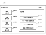
- 1 schematically shows an example of the internal configuration of the management server 160.
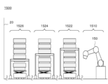
- the other example of the system configuration of the automatic warehouse 1500 is schematically shown.
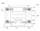
- An example of the structure of the rack 1630 is schematically shown.
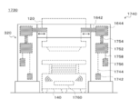
- An example of the structure of the rack 1730 is schematically shown.
- 1 schematically shows an example of the structure of a container 1820.
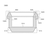
- 1 schematically shows an example of the structure of the container 1920.
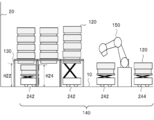
- FIG. 1 schematically shows an example of the inside of the automated warehouse 100.
- FIG. 2 schematically shows an example of the system configuration of the automated warehouse 100.
- the automated warehouse 100 includes one or more containers 120, one or more racks 130, and one or more transport vehicles 140.
- the automated warehouse 100 may include one or more picking devices 150.
- the automated warehouse 100 may include a management server 160.
- the transport vehicle 140 includes a transport vehicle 242 that transports the container 120 between the rack 130 and the picking device 150, and another location inside or outside the automated warehouse 100 from the picking device 150.
- the transport vehicle 242 and the transport vehicle 244 may have the same configuration or different configurations.
- the automated warehouse 100 may be an example of a storage system.
- the container 120 may be an example of the first container, the second container, or the third container.
- the rack 130 may be an example of a pedestal.
- the transport vehicle 140 may be an example of a transport robot.
- the management server 160 may be an example of an operation management unit.
- the transport vehicle 242 may be an example of a transport robot.
- the transport vehicle 244 may be an example of a transport robot.
- the container 120 may be an example of a plurality of containers stacked in the vertical direction.
- the term “one or more” means “one or more”.
- Upward includes not only the case where the direction is upward in the vertical direction but also the case where the angle formed by the direction and the vertical direction is less than 90 degrees.
- the angle between the direction and the vertical direction may be 60 degrees or less, 45 degrees or less, or 30 degrees or less.
- Downward includes not only the case where the direction is downward in the vertical direction but also the case where the angle formed by the direction and the vertical direction is less than 90 degrees.
- the angle between the direction and the vertical direction may be 60 degrees or less, 45 degrees or less, or 30 degrees or less.
- the automated warehouse 100 stores one or more articles.
- Each of the one or more articles is stored, for example, in a state of being housed in the container 120.
- a plurality of containers 120 that are stacked in the vertical direction and stored in a specific rack 130 are arranged above the containers 120 that are stored in the specific rack 130 earlier.
- the containers 120 arranged below are stored so that they can be extracted first from the specific rack 130.
- the container 120 may be moved between the plurality of racks 130. Therefore, among the plurality of containers 120 stacked in a row in the vertical direction and stored in a specific rack 130, the container 120 that was loaded into the automated warehouse 100 earlier in time is not necessarily later in time. It should be noted that they are not placed above the containers 120 that have been stored in.
- a plurality of racks 130 are installed in a matrix on the floor 10 of the automated warehouse 100.
- Each of the plurality of racks 130 supports a plurality of containers 120 stacked in a row.
- Each of the plurality of racks 130 is configured to be able to support, for example, a part of the plurality of vertically stacked containers 120 from the side or the bottom.
- the rack 130 is configured to support a single container 120 included in a plurality of vertically stacked containers 120 from the side or the bottom.
- the rack 130 is configured to support at least two containers 120 included in the plurality of vertically stacked containers 120 from the side or the bottom.
- the rack 130 may support the plurality of containers 120 described above by applying a force to the side surface of some of the containers 120 described above.
- the rack 130 may support the plurality of containers 120 by exerting a force on the lower surface of the part of the containers 120.
- the rack 130 may support the plurality of containers 120 by applying a force to the side surface and the lower surface of some of the containers 120 described above.
- each of the plurality of racks 130 supports the container 120 arranged at the bottom among the plurality of containers 120 stacked in a row.
- the other container 120 is stacked on the one container 120.
- a space is formed below each of the plurality of racks 130.
- the distance H22 between the floor 10 and the lower surface of the container 120 arranged at the bottom among the one or more containers 120 supported by the rack 130 is at least one of the floor 10 and the at least one container 120 mounted on the transport vehicle 140. It is larger than the distance H24 with the upper surface of the container 120 arranged at the top among the containers 120.
- the transport vehicle 140 can freely travel under the plurality of racks 130 arranged in a matrix and transport the container 120 between one position and the other position.
- the transport vehicle 242 transports at least one container 120 between the rack 130 and the picking device 150.
- the transport vehicle 242 may transport at least one container 120 between one rack 130 and another rack 130.
- the one position may be an example of one of the first position and the second position.
- the other position may be an example of the other of the first position and the second position.
- a grid-like travel route is formed under the plurality of racks 130 arranged in a matrix.
- the shape of the travel route is not limited to this embodiment.
- a line-shaped traveling path may be formed under the plurality of racks 130 arranged in a row, and a line-shaped traveling path may be formed under the plurality of racks 130 arranged in a matrix.
- a plurality of paths may be formed.
- the carrier vehicle 242 can move the container 120 in the vertical direction.
- the transport vehicle 242 maintains the container 120 at a relatively low position (sometimes referred to as a travel position) when traveling under the rack 130.
- the transport vehicle 242 moves the container 120 up and down when loading the container 120 into the rack 130 or removing the container 120 from the rack 130.
- the carrier 242 loads the container 120 on the rack 130 according to the following procedure.
- the number of containers 120 loaded in a single rack 130 at one time may be one, or may be two or more.
- the rack 130 supports one or more containers 120, and among the at least one container 120 mounted on the transport vehicle 140, the rack 130 is a single container.
- An example of a procedure for loading the container 120 into the rack 130 will be described by taking the case where the container 120 is newly loaded into the rack 130 as an example.
- the transport vehicle 242 enters below the target rack 130.
- the transport vehicle 242 adjusts the position of the transport vehicle 242.
- the transport vehicle 242 is mounted on the transport vehicle 242 together with the container 120 (which may be referred to as a container A) located at the bottom among the one or more containers 120 supported by the rack 130.
- the position of the carrier 242 is finely adjusted so that the horizontal position of the uppermost container 120 (may be referred to as a container B) of at least one of the existing containers 120 matches.
- the transport vehicle 242 moves the container 120 mounted on the transport vehicle 242 upward to bring the container A and the container B into contact with each other.
- the carrier 242 moves the container 120 mounted on the carrier 242 further upward.
- the bottom of the container A is fitted into the opening of the container B.
- at least one container 120 supported by the rack 130 and at least one container 120 mounted on the transport vehicle 242 simultaneously move upward.
- the transport vehicle 242 stops the movement of the container 120.
- the rack 130 applies a force to the container B to support the container B.
- the transport vehicle 242 lowers the remaining containers 120 to the traveling position.
- the container B is loaded on the rack 130, and the number of containers 120 supported by the rack 130 increases.
- the uppermost container 120 is newly loaded in the rack 130, and the container 120 is loaded in the rack 130 as an example.
- the details of the procedure described were explained.
- the procedure for loading the containers 120 into the rack 130 is not limited to this embodiment.
- a plurality of upper containers 120 may be newly loaded on the rack 130.
- the transport vehicle 242 is a transport vehicle until the container 120 (which may be referred to as a container BX) located at the bottom of the plurality of newly loaded containers 120 is placed at a predetermined position.
- the container 120 mounted on 242 is raised.
- the rack 130 applies a force to the container 120 located at the bottom of the plurality of newly loaded containers 120 to support the container 120.
- the container A may be an example of the first container.
- the container B may be an example of the second container.
- the container BX may be an example of the second container.
- the carrier 242 takes out the container 120 from the rack 130 according to the following procedure.
- the number of the containers 120 taken out from the single rack 130 at one time may be one, or may be two or more.
- the transport vehicle 140 may already be loaded with another container 120, or may not be loaded with another container 120.
- a single container 120 among the one or more containers 120 supported by the rack 130 is used by using the carrier vehicle 140 in which the container 120 is not mounted. An example of the procedure for removing the container 120 from the rack 130 will be described with reference to the case where the container 120 is extracted.
- the carrier 242 enters below the target rack 130.
- the transport vehicle 242 adjusts the position of the transport vehicle 242.
- the transport vehicle 242 includes a container 120 (which may be referred to as a container A) located at the bottom of one or more containers 120 supported by the rack 130, and a mounting surface of the transport vehicle 242. The position of the transport vehicle 242 is finely adjusted so that the positions in the horizontal direction coincide with.
- the carrier 242 raises the mounting surface of the carrier 242 until the mounting surface of the carrier 242 supports the container A.
- the rack 130 also applies a force to the container A to support the container A. Therefore, in this state, even if the mounting surface is lowered, the container A does not move downward. Therefore, after the mounting surface of the transport vehicle 242 supports the container A, the rack 130 reduces the force acting on the container A. This allows the one or more containers 120 supported by the rack 130 to move downward.
- the carrier 242 lowers the mounting surface. At this time, as the mounting surface is lowered, the one or more containers 120 supported by the rack 130 are also moved downward. As a result, the container A is taken out from the rack 130, and the number of containers 120 supported by the rack 130 is reduced.
- the one or more containers 120 supported by the rack 130 include the container A and the one or more containers 120 stacked above the container A, the one or more containers stacked above the container A
- the container 120 which may be referred to as a container C
- the transport vehicle 242 stops the lowering of the mounting surface.
- the rack 130 applies a force to the container C to support the container C.
- the transport vehicle 242 lowers the mounting surface to the traveling position. As a result, the container A is taken out from the rack 130, and the number of containers 120 supported by the rack 130 is reduced.
- the rack 130 to the container A is not used.
- the procedure in which the container 120 is removed from the rack 130 for example, when the rack 130 supports the container 120 located at the bottom of the one or more containers 120 stacked above the container A after the removal of the container 120. Details were explained. However, the procedure for removing the container 120 from the rack 130 is not limited to this embodiment.
- the rack 130 may include any one of the one or more containers 120 stacked above the container A (when referred to as a container CX). May be supported). Thereby, the plurality of containers 120 are taken out from the rack 130 at one time.
- the mounting surface of the carrier vehicle 242 may be an example of a mounting portion.
- the container C may be an example of the third container.
- the container CX may be an example of the third container.
- the automated warehouse 100 can stack the containers 120 up to a position exceeding the height of the rack 130. This significantly reduces the size and mass of the rack 130 as compared to the case where the container 120 is housed inside the rack 130. For example, the height of the rack 130 can be suppressed to the height of several containers 120. Further, according to the present embodiment, the transport vehicle 140 can travel under the rack 130 supporting the container 120 while the container 120 is mounted. As a result, it is not necessary to provide a traveling route for the transport vehicle 140 between the two adjacent racks 130. As a result, the storage density of the containers 120 is improved.
- the container 120 houses one or more items.
- the material, shape, and size of the container 120 are determined, for example, in consideration of the storage efficiency of the articles and the ease of handling.
- the shape and size of the container 120 are not particularly limited, but for example, the width is 20 cm to 1 m, the height is 20 cm to 1 m, and the depth is 20 cm to 1 m.
- the rack 130 supports one or more containers 120.
- the rack 130 may support a plurality of containers 120 stacked in a row.
- the rack 130 applies a force to the container 120 located at the bottom of one or more containers 120 to support the container 120 located at the bottom.
- the transport vehicle 140 having the at least one container 120 mounted therein can travel below the container 120 supported by the rack 130.
- one or more containers 120 may be supported.
- the position where the rack 130 exerts a force on the container 120 is set such that the distance H22 described with reference to FIG. 2 is larger than the distance H24.
- the carrier vehicle 140 carries at least one container 120 between one position and another position. In one embodiment, carrier 140 loads containers 120 onto racks 130. In another embodiment, carrier 140 removes container 120 from rack 130.
- the picking device 150 transfers an article between one container 120 and another container 120.
- the picking device 150 takes out the article stored in the container 120 mounted on the transport vehicle 242 and stores the article in the container 120 loaded on the transport vehicle 244.
- the picking device 150 takes out an article stored in the container 120 mounted on the transport vehicle 244 and stores the article in the container 120 loaded on the transport vehicle 242.
- the management server 160 manages the storage status of items.
- the management server 160 may manage each part of the automated warehouse 100.
- the management server 160 manages the state of each part of the automated warehouse 100.
- the management server 160 may manage the operation of each of the one or more guided vehicles 140.
- the management server 160 may manage the operation of each of the one or more racks 130.
- Each unit of the automated warehouse 100 may be realized by hardware, software, or hardware and software. At least a part of each unit of the automated warehouse 100 may be realized by a single server or may be realized by a plurality of servers. At least a part of each unit of the automated warehouse 100 may be realized on a virtual server or a cloud system. At least a part of each unit of the automated warehouse 100 may be realized by a personal computer or a mobile terminal. Examples of the mobile terminal include a mobile phone, a smartphone, a PDA, a tablet, a notebook computer or a laptop computer, a wearable computer, and the like. Each unit of the automated warehouse 100 may store information using a distributed ledger technology such as a block chain or a distributed network.
- a distributed ledger technology such as a block chain or a distributed network.
- the information processing apparatus having the above-described general configuration includes (i) a data processing apparatus having a processor such as CPU and GPU, ROM, RAM, communication interface, etc., and (ii) keyboard, pointing device, touch panel, camera, voice input.
- a data processing apparatus having a processor such as CPU and GPU, ROM, RAM, communication interface, etc.
- keyboard pointing device, touch panel, camera, voice input.
- storage device such as memory, HDD, SSD (external (Including a storage device).
- the data processing device or the storage device may store the program.
- the above program causes the information processing apparatus to execute the operation defined by the program by being executed by the processor.
- the above program may be stored in a non-transitory computer-readable recording medium.
- the above program may be stored in a computer-readable medium such as a CD-ROM, a DVD-ROM, a memory or a hard disk, or may be stored in a storage device connected to a network.
- the above program may be a program for causing a computer to function as the automated warehouse 100 or a part thereof.
- the above program may include a module that defines the operation of each unit of the automated warehouse 100. These programs or modules work on a data processing device, an input device, an output device, a storage device, etc. to cause a computer to function as each part of the automated warehouse 100, or to cause the computer to execute an information processing method in each part of the automated warehouse 100.
- the above program may be installed in a computer forming at least a part of the automated warehouse 100 from a computer-readable medium or a storage device connected to a network. By executing the above program, the computer may function as at least a part of each unit of the automated warehouse 100.
- the information processing described in the above program is a concrete example in which the software associated with the program and the various hardware resources of the automated warehouse 100 or a part thereof cooperate with each other when the program is read by a computer. Functions as a means. Then, the above-mentioned specific means realizes the calculation or processing of information according to the purpose of use of the computer in this embodiment, whereby the automatic warehouse 100 according to the purpose of use is constructed.
- the above program may be a program for causing a computer to execute the information processing method in the automated warehouse 100 or a part thereof.
- the above information processing method may be a method in which at least one of the rack 130 and the transport vehicle 140 loads the container 120 on the rack 130.
- the above information processing method may be a method in which at least one of the rack 130 and the transport vehicle 140 takes out the container 120 from the rack 130.
- the above information processing method may be a method in which the management server 160 controls at least one of the rack 130 and the transport vehicle 140.
- FIG. 3 schematically shows an example of the rack 130.
- the rack 130 includes a rack body 320 and a container support 340.
- the rack body 320 is installed on the floor 10 and bears the load of the container 120.
- a movable container support 340 is arranged inside the container 120.
- the rack body 320 may be an example of a plurality of columns.
- the container support 340 may be an example of a restriction unit.
- the container support 340 may be an example of a movable support unit.
- the container support 340 supports the container 120 and transfers the load of the container 120 to the rack body 320.
- the container support 340 is configured, for example, to support one or more containers 120 from the side or below and to transfer the load of the one or more containers 120 to at least one of the rack body 320 and the floor 10.
- the lower end of the container support 340 is rotatably attached to the rack body 320.
- the container support 340 rotates and the upper end of the container support 340 moves, so that the container support 340 supports the container 120 or releases the container 120.
- the upper end of the container support 340 supports the recess 302 formed on the side surface of the container 120.
- the position and manner in which the container support 340 supports the container 120 are not particularly limited.
- the container support 340 lifts or pushes up the bottom surface of the container 120 and at least one of the irregularities formed on the side surface of the container 120 to apply an upward force to the container 120, Supports the container 120.
- the container support 340 holds or holds the side surface of the container 120 to apply an upward or sideward force to the side surface of the container 120 to support the container 120. Details of the rack 130 will be described later.
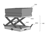
- FIG. 4 schematically shows an example of the carrier vehicle 140.
- the transport vehicle 140 includes a lift table 420, a lift device 440, and a support operation unit 460.
- the lifting table 420 may be an example of a mounting unit.
- the lifting device 440 may be an example of a lifting unit.
- the support operation unit 460 may be an example of a release unit.
- the lifting table 420 is configured to be able to mount at least one container 120. According to the present embodiment, by fitting a part of the bottom of the other container 120 into the opening of the one container 120, the other container 120 is stacked on the one container 120. Therefore, the mounting surface of the lifting table 420 may be formed with a recess into which a part of the bottom of the container 120 is fitted.
- the lifting device 440 moves the lifting table 420 in the vertical direction. Accordingly, the carrier vehicle 140 can move the container 120 mounted on the lifting table 420 upward or downward.
- the support operation unit 460 operates the container support 340 of the rack 130.
- the container support 340 supports the container 120 and releases the container 120.
- the carrier vehicle 140 can load the target container 120 into the target rack 130 or take out the target container 120 from the target rack 130 at an arbitrary timing.
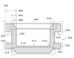
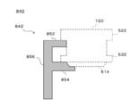
- FIG. 5 schematically shows an example of the structure of the container 120.
- FIG. 5 may be an example of a sectional view when the container 120 is cut along a plane perpendicular to the extending direction of the container 120.
- the container 120 includes a bottom plate 510 and side walls 520.
- the bottom plate 510 is located below the container 120. An article is placed on one surface of the bottom plate 510.
- the bottom plate 510 has a convex portion 514 that projects to the side of the other surface of the bottom plate 510.
- the outer edge portion 516 of the convex portion 514 may be inclined with respect to the normal direction of one surface of the bottom plate 510.
- one end of the side wall 520 is in contact with the outer edge 512 of the bottom plate 510 and extends to one side of the bottom plate 510.
- the other end of the side wall 520 forms an opening 560.
- a space for containing the article is formed inside the container 120.
- the other end of the side wall 520 may have an inclined portion 546 that is inclined with respect to the normal direction of the bottom plate 510.
- the ratio (W52/W54) of the thickness W52 of the inclined portion 546 to the thickness W54 of the side wall 520 is, for example, the accuracy of control of at least one of the position and the attitude of the carrier vehicle 140, the manufacturing accuracy of the rack 130, and the rack 130. It is determined based on at least one of the installation accuracy and the manufacturing accuracy of the container 120.
- the angle formed by the inclined portion 546 with respect to the normal direction of the bottom plate 510 is, for example, the effective mass of the containers 120, the coefficient of friction between the containers 120, the coefficient of friction between the containers 120 and the transport vehicle 140, and the lifting speed of the containers 120. , Is determined based on at least one of the set values of the ascending/descending speed of the container 120.
- the ascending/descending speed of the container 120 may be determined based on the output of an arbitrary sensor such as a force sensor, for example
- the absolute value of the difference between the angle formed by the inclined portion 546 of the side wall 520 with respect to the normal line direction of the bottom plate 510 and the angle formed by the outer edge portion 516 of the protrusion 514 with respect to the normal line direction of the bottom plate 510 is predetermined. May be smaller than the value. As a result, collapse of the containers 120 is suppressed even when a plurality of containers 120 are stacked. Further, since the side wall 520 has the inclined portion 546 and the outer edge portion 516 of the convex portion 514 is inclined, the horizontal position between the one container 120 and the other container 120 may be slightly displaced. However, when the plurality of containers 120 are stacked, the protrusion 514 of the other container 120 is fitted into the opening 560 of the one container 120. As a result, the requirement for the positioning accuracy of the carrier vehicle 140 is reduced, and the loading and unloading efficiency of the containers 120 is improved.
- the convex portion 522 and the convex portion 532 are formed on the outer surface of the side wall 520.
- the recess 302 is formed.
- the container support 340 can support the container 120 by applying a force to at least one of the lower surface 524 of the convex portion 522 and the lower surface 534 of the convex portion 532.
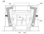
- FIG. 6 schematically shows an example of the structure of the rack 130 in a state where the container support 340 supports the container 120.
- FIG. 7 schematically shows an example of the structure of the rack 130 in a state in which the container support 340 releases the container 120 and the lifting table 420 of the transport vehicle 140 supports the container 120.
- FIG. 6 schematically shows an example of a state in which the container support 340 supports the container 120 and the vertical movement of the container 120 is restricted by the container support 340.
- FIG. 7 schematically illustrates an example of a state in which the container support 340 does not support the container 120 and the vertical movement of the container 120 is not limited by the container support 340.
- the rack 130 includes a rack body 320 and a pair of container supports 340.
- the rack main body 320 has a base portion 622, columns 624, and beams 626.
- the rack main body 320 may include at least a pair of base portions 622, a pair of columns 624, and a beam 626. As shown in FIG. 3, the rack main body 320 may have four base portions 622, four columns 624, and four beams 626.
- each of the pair of container supports 340 may include a support member 642, a mounting member 644, and a spring 646.
- the support member 642 may be an example of an action member and a restriction unit.
- the spring 646 may be an example of a drive unit.
- One of the pair of columns 624 may be an example of one of the first column and the second column.
- the other of the pair of columns 624 may be an example of the other of the first column and the second column.
- One of the pair of container supports 340 may be an example of one of the first limiting portion and the second limiting portion.
- the other of the pair of container supports 340 may be an example of the other of the first limiting section and the second limiting section.
- One of the pair of springs 646 may be an example of one of the first elastic body and the second elastic body.
- the other of the pair of springs 646 may be an example of the other of the first elastic body and the second elastic body.
- the container support 340 may be an example of a movable support unit.
- the spring 646 may be an example of the switching unit.
- the foundation 622 is arranged between the floor 10 on which the rack 130 is installed and at least one of the plurality of columns 624, and supports the at least one column 624.
- the base portion 622 may include a column driving unit (not shown) that moves the column 624 up and down.
- the pillar drive unit may receive a signal from the transport vehicle 140 or the management server 160 and move the pillar 624 up and down. Thereby, the position where the rack 130 supports the container 120 can be adjusted.
- the support column 624 and the beam 626 support the load of the container 120.
- the beam 626 may be disposed, for example, between a pair of columns 624 facing each other, and may connect the pair of columns 624.
- the columns 624 and the beams 626 may be arranged so that the container 120 can move in the vertical direction near the center of the rack body 320.
- the beam 626 is fixed to both the pair of columns 624.
- the beam 626 is not limited to this embodiment.
- the beam 626 may be rotatably attached to one strut 624 and removably attached to the other strut 624.
- a beam driving unit (not shown) that drives the beam 626 may be arranged on one of the columns 624.
- the beam driver may receive a signal from the carrier vehicle 140 or the management server 160 to drive the beam 626.
- the degree of freedom in traveling of the carrier vehicle 140 equipped with a large number of containers 120 is improved.
- the efficiency of loading or unloading the article is improved.
- one end of the support member 642 is rotatably attached to the support column 624 via the attachment member 644.
- the support member 642 may transfer the load of the container 120 to the support column 624 via the attachment member 644.
- the position of the upper surface 652 of the support member 642 changes as the support member 642 rotates about one end. Accordingly, the support member 642 can support the container 120 or release the container 120. As a result, the vertical movement of the container 120 is restricted or the restriction is lifted.
- the support member 642 applies a force to the container 120 arranged at a predetermined position to support the container 120. Accordingly, the support member 642 restricts the container 120 from moving at least downward. On the other hand, when the support member 642 moves, the force acting on the container 120 decreases, the container 120 is released, and the container 120 is allowed to move downward.
- the support member 642 closes at least a part of the movement path of the container 120 mounted on the lift table 420 of the transport vehicle 140. This restricts the container 120 from moving upward. On the other hand, when the support member 642 moves, the movement path of the container 120 is secured, and the container 120 is allowed to move upward.
- the attachment member 644 rotatably attaches one end of the support member 642 to the support column 624.
- the position of the upper surface 652 of the support member 642 may change.
- the load of the container 120 may be transmitted to the support column 624.
- the spring 646 drives the support member 642.
- the spring 646 drives the support member 642 between a limit position where the support member 642 limits the movement of the container 120 and a release position where the support member 642 releases the limit.
- the spring 646 has one end coupled to the inside of the column 624. The other end of spring 646 is coupled to support member 642. Accordingly, the spring 646 can urge the support member 642. According to the present embodiment, the spring 646 biases the support member 642 from the outside of the rack 130 toward the inside.
- the spring 646 arranges the support member 642 at the above-mentioned limit position. To do. At this time, the container 120 is supported by the support member 642.
- the carrier 140 raises the lifting table 420, and the lifting table 420 supports the container 120.
- the transport vehicle 140 pushes the support member 642 from the inside of the rack 130 to the outside using the support operation unit 460.
- the support member 642 rotates around the connection point with the mounting member 644.
- the spring 646 positions the support member 642 in the release position. At this time, the container 120 is released and allowed to move upward or downward.
- adjusting the spring 646 installation position causes the spring 646 to bias the support member 642 from the inside to the outside of the rack 130.
- the spring 646 may arrange the support member 642 in the above-mentioned release position when an external force larger than a predetermined threshold is not applied to the support member 642.
- the spring 646 may arrange the support member 642 in the above-mentioned limit position.
- the spring 646 can switch the state of the rack 130 by moving the container support 340. For example, the spring 646 moves the container support 340 to switch between a state in which the rack 130 supports the container 120 and a state in which the rack 130 does not support the container 120. Further, the spring 646 can switch the state of the container 120 by moving the container support 340. For example, the spring 646 moves the container support 340 to switch between a state in which the movement of the container 120 is restricted by the container support 340 and a state in which the movement of the container 120 is not restricted by the container support 340.
- the means for urging the support member 642 is not limited to the spring 646.
- the spring 646 may be replaced with an elastic body such as rubber.
- balance weights, actuators, cam structures, etc. may be utilized.
- the rack 130 includes the pair of container supports 340.
- the spring constant of the spring 646 of the one container support 340 and the spring constant of the spring 646 of the other container support 340 may be the same or different.
- the above threshold value for the one container support 340 may be an example of one of the first threshold value and the second threshold value.
- the above threshold for the other container support 340 may be an example of the other of the first threshold and the second threshold.
- the position of the container support 340 is changed in response to the conveyance vehicle 140 applying an external force to the support member 642 of the rack 130.
- a spring 646 is installed.
- the method of changing the position of the container support 340 is not limited to this embodiment.
- the position of the container support 340 may change in response to the rack 130 receiving at least one of force, power, power and signals from the carrier 140.
- the signal may be an electric signal or a wireless signal.
- FIG. 8 schematically shows an example of a sectional shape of the support member 842.
- the support member 842 is different from the support member 642 in that it supports not only a part of the protrusion 522 of the container 120 but also a part of the protrusion 532 and a part of the protrusion 514 of the container 120.
- Other configurations of the support member 842 may have the same features as the corresponding configurations of the support member 642.
- the support member 842 includes a support portion 852, a support portion 854, and a connecting portion 856.
- the support portion 852 supports a part of the convex portion 522 of the container 120.
- the support part 854 supports a part of the convex part 532 and a part of the convex part 514 of the container 120.
- the surface shape of the support portion 854 may be configured to match the surface shape of part of the convex portion 532 and part of the convex portion 514.
- the connecting portion 856 connects the supporting portion 852 and the supporting portion 854.
- the connecting portion 856 is rotatably attached to the support column 624 via the attachment member 644 at one end portion.
- the connecting portion 856 is connected to the supporting portion 852 at the other end.
- the connecting portion 856 is coupled to the supporting portion 854 at a position between the one end and the other end.
- the support member 842 may be an example of an action member and a restriction unit.
- the support member 842 may be an example of a movable support unit.
- the support portion 852 may be an example of a movable support portion.
- the support portion 854 may be an example of a movable support portion.
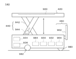
- FIG. 9 schematically shows an example of the structure of the carrier vehicle 140.
- the transport vehicle 140 includes a lift table 420, a lift device 440, a support operation unit 460, a control unit 930, a sensing unit 932, a communication unit 934, a power supply 936, a front wheel 980, and a drive unit.
- a wheel 982 and a motor 984 are provided.
- a recess 920 is formed on the mounting surface of the lifting table 420.
- the lifting device 440 has a pantograph 942 and an actuator 944.
- the support operating section 460 has an operating member 962 and a motor 964.
- the sense unit 932 may be an example of a detection unit.
- control unit 930 controls the operation of the carrier vehicle 140. Details of the control unit 930 will be described later.
- the sense unit 932 includes various sensors.
- the sense unit 932 may include a position sensor for acquiring information indicating the position of the transport vehicle 140.
- the sense unit 932 may include a load sensor that detects a load applied to the lifting table 420.
- the sense unit 932 may include a lift amount sensor that detects the amount of movement of the lift table 420.
- the position sensor As the position sensor, (i) a distance measuring sensor that measures the distance from the wall 20 of the automated warehouse 100, and (ii) information given to a specific position on the floor 10 and acquiring information indicating the position.
- a sensor etc. are illustrated.
- the sensor may be a camera, a magnetic sensor, or a beacon receiver.
- the communication unit 934 transmits/receives information to/from at least one of the rack 130, another transport vehicle 140, the picking device 150, and the management server 160.
- the communication unit 934 may send and receive information to and from the container 120.
- the communication method between the communication unit 934 and another device is not particularly limited.
- the power supply 936 supplies electric power to each part of the carrier vehicle 140.
- the power source 936 may include at least one of a power generation device and a power storage device.
- the front wheels 980 and the drive wheels 982 support the carrier vehicle 140.
- the motor 984 drives the drive wheels 982 to move the transport vehicle 140.
- the convex portion 514 of the container 120 is fitted into the concave portion 920 when the lifting table 420 supports the container 120.
- the surface shape of the recess 920 may be configured to match the surface shape of the protrusion 514.
- the pantograph 942 supports the lifting table 420.
- the actuator 944 drives the pantograph 942 to raise and lower the lift table 420.
- the operation member 962 is driven by the motor 964 to restrict the movement of the container 120 or release the restriction.
- the motor 964 drives the operation member 962.
- one end of the operating member 962 is coupled to the rotation shaft of the motor 964.
- the operation member 962 When the operation member 962 is arranged at the initial position, the other end of the operation member 962 is not in contact with the support member 642 of the container support 340. At this time, the support member 642 supports the container 120, and the vertical movement of the container 120 is restricted.
- the motor 964 rotates the operating member 962
- the other end of the operating member 962 pushes the support member 642 of the container support 340 from the inside of the rack 130 to the outside. This releases the restriction on the movement of the container 120.
- the motor 964 rotates the operation member 962 and the operation member 962 returns to the initial position, the vertical movement of the container 120 is restricted.
- the support operation unit 460 applies a force to the support member 642 disposed at the limit position to move the support member 642 to the release position, and the movement limitation of the container 120 is performed.
- An example of a method of releasing has been described.
- the method of canceling the movement restriction of the container 120 is not limited to this embodiment.
- the support operation unit 460 applies electric power or power to the container support 340 to operate the drive unit that drives the support member 642. Thereby, the support operation part 460 can move the support member 642 arranged at the limit position to the release position.
- the mechanism for applying power to the container support 340 by the support operating unit 460 includes a ball screw, a rotary shaft, a pulley, a belt, a chain, a gear, a gear, a gear, a rack and pinion, a Geneva mechanism, a link mechanism, a crank mechanism, and these. A combination is exemplified.
- the support operation unit 460 sends a control signal to the container support 340 to activate the drive unit that drives the support member 642. Thereby, the support operation part 460 can move the support member 642 arranged at the limit position to the release position.
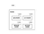
- FIG. 10 schematically shows an example of the internal configuration of the control unit 930.
- the control unit 930 includes a communication control unit 1020, a travel control unit 1030, a lifting device control unit 1040, and an operation member control unit 1050.
- the traveling control unit 1030 may be an example of a position estimation unit.
- the lifting device control unit 1040 may be an example of a lifting control unit and a position estimation unit.
- the operation member control unit 1050 may be an example of a release control unit.
- the communication control unit 1020 controls communication between the carrier vehicle 140 and external devices.
- the communication control unit 1020 may control the operation of the communication unit 934.
- the traveling control unit 1030 controls the movement of the carrier vehicle 140.
- the traveling control unit 1030 acquires the information output by the position sensor included in the sense unit 932.
- the traveling control unit 1030 estimates the position of the carrier vehicle 140 based on the information output by the position sensor.
- the traveling control unit 1030 controls the motor 984 based on the estimated position of the transport vehicle 140 to move the transport vehicle 140 to the destination.
- the lifting device control unit 1040 controls the operation of the lifting device 440.
- the lifting device control unit 1040 acquires information output by the position sensor included in the sense unit 932.
- the lifting device control unit 1040 estimates the position of the transport vehicle 140 based on the information output by the position sensor.
- the lifting device control unit 1040 controls the lifting device 440 to move the lifting table 420 upward.
- the first condition may be a condition that the error between the estimated position of the carrier vehicle 140 and the destination of the carrier vehicle 140 is smaller than a predetermined value.
- the lifting device control unit 1040 acquires the information output by the load sensor or the lifting amount sensor included in the sensing unit 932. When the load applied to the lifting table 420 detected by the load sensor or the movement amount of the lifting table 420 detected by the lifting amount sensor satisfies the second predetermined condition, the lifting device control unit 1040 causes the lifting device controller 1040 to move up and down. The device 440 is controlled to continue moving above the lifting table 420.
- the second condition is, for example, a condition that the load is larger than a predetermined value or a condition that the movement amount is within a predetermined numerical range. Accordingly, the lifting device control unit 1040 can detect contact between the container 120 supported by the rack 130 and the lifting table 420 or the container 120 mounted on the lifting table 420. Further, the lifting device control unit 1040 can detect the timing at which the movement restriction of the container 120 by the rack 130 is released.
- the lifting device control unit 1040 When the load applied to the lifting table 420 detected by the load sensor or the movement amount of the lifting table 420 detected by the lifting amount sensor satisfies the third predetermined condition, the lifting device control unit 1040 causes the lifting device controller 1040 to move up and down.
- the device 440 is controlled to stop the movement above the lifting table 420.
- the third condition include a condition that the load is smaller than a predetermined value and a condition that the movement amount is within a predetermined numerical range.
- the lifting device control unit 1040 can detect the completion of loading or unloading the target containers 120. Further, the lifting device control unit 1040 can detect the timing at which the movement restriction of the container 120 by the rack 130 is restored.
- the lifting device control unit 1040 controls the lifting device 440 to move the lifting table 420 upward.
- the fourth condition may be a condition that the error between the estimated position of the carrier vehicle 140 and the destination of the carrier vehicle 140 is smaller than a predetermined value.
- the lifting device control unit 1040 causes the lifting device controller 1040 to move up and down.
- the device 440 is controlled to move the lifting table 420 downward.
- the lifting/lowering device controller 1040 may control the lifting/lowering device 440 to stop the lifting/lowering of the lifting/lowering table 420 for a certain period before moving the lifting/lowering table 420 downward.
- Examples of the fifth condition include a condition that the load is larger than a predetermined value and a condition that the movement amount is within a predetermined numerical range.
- the lifting device control unit 1040 can detect contact between the container 120 supported by the rack 130 and the lifting table 420 or the container 120 mounted on the lifting table 420. Further, the lifting device control unit 1040 can detect the timing at which the movement restriction of the container 120 by the rack 130 is released.
- the operation member control unit 1050 controls the operation of the support operation unit 460.
- the operation member control unit 1050 acquires information output by the load sensor or the lift amount sensor included in the sense unit 932.
- the operation member control unit 1050 causes the support operation unit to operate.
- the movement restriction of the container 120 may be released by operating 460.
- the operation member control unit 1050 causes the support operation unit to operate.
- the movement restriction of the container 120 may be restored by operating 460.
- the operation member control unit 1050 causes the support operation unit to operate.
- the movement restriction of the container 120 may be released by operating 460.
- the operation member control unit 1050 sets the support.
- the operation unit 460 may be operated to restore the movement restriction of the container 120. Examples of the sixth condition include a condition that the load is within the limit of the weight capacity of the lifting table 420 and a condition that the movement amount is within a predetermined numerical range.
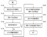
- FIG. 11 schematically shows an example of information processing in the control unit 930.
- FIG. 11 schematically illustrates an example of a method in which the transport vehicle 140 controls the operation of loading the containers 120 into the rack 130.
- the traveling control unit 1030 controls the motor 984 to cause the transport vehicle 140 to enter under the rack 130 that is the destination.
- the transport vehicle 140 has a container 120 to be loaded on the rack 130.
- the elevating device controller 1040 controls the elevating device 440 to start elevating the elevating table 420 after confirming that the transport vehicle 140 has moved to an appropriate position.
- the lifting device control unit 1040 monitors the load applied to the lifting table 420 detected by the load sensor or the movement amount of the lifting table 420 detected by the lifting amount sensor.
- the lifting device control unit 1040 determines whether or not the above-mentioned load or movement amount satisfies a predetermined condition.
- the above conditions may be conditions for detecting contact between the container 120 supported by the rack 130 and the lifting table 420 or the container 120 mounted on the lifting table 420.
- the above condition may be the second condition described above.
- the lifting device control unit 1040 determines that the load or the movement amount satisfies the condition. Is transmitted to the operation member control unit 1050. At this time, the lifting device control unit 1040 may control the lifting device 440 to suspend the lifting of the lifting table 420.
- the operation member control unit 1050 operates the support operation unit 460 to release the movement restriction of the container 120. This allows the container 120 to move further upward.
- step S1132 the lifting device control unit 1040 controls the lifting device 440 to further lift the lifting table 420.
- the lifting device control unit 1040 controls the lifting device 440 to stop the lifting table 420.
- the operation member control unit 1050 operates the support operation unit 460 to restore the movement restriction of the container 120. As a result, the number of containers 120 supported by the rack 130 increases.
- the lifting device control unit 1040 controls the lifting device 440 to lower the lifting table 420 to the traveling position. This completes the loading operation of the containers 120.
- FIG. 12 schematically shows an example of information processing in the control unit 930.
- FIG. 12 schematically shows an example of a method in which the transport vehicle 140 controls the operation of removing the container 120 from the rack 130. 12, steps similar to those in FIG. 11 are designated by the same reference numerals as those in FIG. 11, and description thereof is omitted.
- the lifting device control unit 1040 controls the lifting device 440 to lower the lifting table 420.
- the lifting device control unit 1040 controls the lifting device 440 to stop the lifting table 420.
- the operation member control unit 1050 operates the support operation unit 460 to restore the movement restriction of the container 120. As a result, a desired number of containers 120 are taken out from the rack 130, and the number of containers 120 supported by the rack 130 is reduced.
- the lifting device control unit 1040 controls the lifting device 440 to lower the lifting table 420 to the traveling position. This completes the work of taking out the container 120.
- FIG. 13 schematically shows an example of information processing in the control unit 930.
- FIG. 13 schematically illustrates an example of a method in which the transport vehicle 140 controls the operation of removing the container 120 from the rack 130.
- the details of the take-out work will be described by exemplifying a case where the container 120 targeted for the take-out work is not the container 120 located at the bottom of the plurality of containers 120 supported by the rack 130.
- step S1320 the control unit 930 controls the transport vehicle 140 to move the transport vehicle 140 below the destination rack AA.
- control unit 930 controls the transport vehicle 140 by the procedure similar to that described with reference to FIG. 12, and takes out the container X from the rack LA. Further, the control unit 930 controls the transport vehicle 140 to cause the transport vehicle 140 to enter under the rack LB different from the rack LA. The control unit 930 controls the transport vehicle 140 by the same procedure as that described with reference to FIG. 11 to load the container X into the rack LB.
- control unit 930 controls the transport vehicle 140 to cause the transport vehicle 140 to enter under the rack LA again.
- the control unit 930 controls the transport vehicle 140 to take out the container Y from the rack LA by a procedure similar to the procedure described with reference to FIG. This completes the work of taking out the container 120.
- the details of the work of taking out the container 120 have been described by taking the case where one transport vehicle 140 performs all the work as an example.
- the operation of taking out the container 120 is not limited to this embodiment.
- a plurality of vehicles 140 may cooperate to carry out the operation of taking out the container 120.
- the transport vehicle VA takes out the container X from the rack LA and loads the container X on the rack LB.
- the transport vehicle VB takes out the container X from the rack LA.
- FIG. 14 schematically shows an example of the internal configuration of the management server 160.
- the management server 160 includes a communication control unit 1422, an inventory management unit 1424, a device management unit 1426, a request reception unit 1428, and a storage unit 1440.
- the storage unit 1440 has an article information storage unit 1442, a container information storage unit 1444, a rack information storage unit 1446, and a guided vehicle information storage unit 1448.
- the communication control unit 1422 controls communication between the management server 160 and at least one of the container 120, the rack 130, the transport vehicle 140, and the picking device 150.
- the communication control unit 1422 may control communication between the management server 160 and the user's communication terminal (not shown).
- the communication method is not particularly limited.
- the inventory management unit 1424 manages the inventory status of the automated warehouse 100. Thereby, the management server 160 can appropriately store the article. Specifically, the inventory management unit 1424 manages the information for identifying each of the plurality of items and the information for identifying the container in which the item is stored in association with each other.
- the inventory management unit 1424 includes information that identifies each of the plurality of containers 120, information that identifies the rack 130 in which the containers are loaded, and information that indicates in which stage of the rack the relevant containers are arranged. Are managed in association with each other.
- the device management unit 1426 manages at least one of the container 120, the rack 130, the transport vehicle 140, and the picking device 150.
- the device management unit 1426 may manage at least one state of the container 120, the rack 130, the transport vehicle 140, and the picking device 150.
- the device management unit 1426 may control the operation of at least one of the container 120, the rack 130, the transport vehicle 140, and the picking device 150.
- the device management unit 1426 allocates the transfer work to each of the one or more transfer vehicles 140. More specifically, the device management unit 1426 transmits, to the transport vehicle 140, information indicating the position of the container 120 that is the target of the transport work and the position of the transport destination. The device management unit 1426 may transmit information indicating the travel route of the transport vehicle 140 to the transport vehicle 140.
- the request receiving unit 1428 receives various requests from at least one of the container 120, the rack 130, the transport vehicle 140, the picking device 150, and the user's communication terminal.
- the request receiving unit 1428 may process the above request. For example, the request receiving unit 1428 receives, from each device, information indicating an abnormality of itself or another device and information requesting that the abnormality be dealt with.
- the storage unit 1440 stores various information used for information processing in the management server 160.
- the item information storage unit 1442 stores the information for identifying each of the plurality of items and the information for identifying the container in which the item is stored in association with each other.
- the article information storage unit 1442 may store the information for identifying each of the plurality of articles and the information indicating the specifications of the article in association with each other. Examples of the information indicating the specifications of the article include size, shape, mass, raw material, expiration date, expiration date, expiration date, price, and the like.
- the article information storage unit 1442 may store the information for identifying each of the plurality of articles and the information regarding the physical distribution of the article in association with each other. Examples of the information regarding the physical distribution of the goods include an elapsed time after the goods are stored in the automated warehouse 100, an average residence time of the same kind of goods, and the like.
- the container information storage unit 1444 stores information that identifies each of the plurality of containers 120 and information that identifies the rack in which the containers are loaded, in association with each other.
- the container information storage unit 1444 includes information for identifying each of the plurality of containers 120, information for identifying the rack 130 in which the container is loaded, and information indicating in which stage of the rack the container is arranged. And may be stored in association with each other.
- the rack information storage unit 1446 stores information that identifies each of the plurality of racks 130, information that indicates the position of the rack, and information that indicates the current status of the rack in association with each other.
- Examples of the current status of the rack 130 include the number of containers 120 loaded in the rack, the number of containers 120 that can be further loaded in the rack, the presence/absence of an abnormality, and the driving status of each drive unit. ..
- the carrier information storage unit 1448 stores the information for identifying each of the plurality of 140 and the information indicating the current status of the carrier in association with each other.
- the current status of the carrier vehicle 140 includes the presence or absence of the carrier work assigned to the carrier vehicle, the content of the carrier work, the current position of the carrier vehicle, the number of containers 120 mounted on the carrier vehicle, the carrier vehicle. Examples of the number of containers 120 that can be further mounted on the disk, whether or not an abnormality has occurred, the driving status of each driving unit, and the like are illustrated.
- FIG. 15 schematically shows another example of the system configuration of the automated warehouse 1500.
- the automated warehouse 1500 is different from the automated warehouse 100 described with reference to FIGS. 1 to 14 in that the automated warehouse 1500 includes a plurality of racks 130 that support the containers 120 at different positions.
- the automated warehouse 1500 in FIG. 15 may have the same features as the automated warehouse 100 in FIGS. 1 to 14.
- the inside of the automated warehouse 1500 is divided into an area 1510, an area 1522, an area 1524, and an area 1526.
- a picking device 150 is arranged in the area 1510.
- Area 1522 is the area closest to area 1510
- area 1526 is the area farthest from area 1510.
- the position where each of the one or more racks 130 arranged in the area 1522 supports the container 120 is higher than the position where each of the one or more racks 130 arranged in the area 1524 supports the container 120. Set to position.
- the racks 130 arranged in the area 1522 more containers 120 are loaded and unloaded at one time than when the racks 130 arranged in the area 1524 are used. be able to.
- the position where each of the one or more racks 130 arranged in the area 1524 supports the container 120 is higher than the position where each of the one or more racks 130 arranged in the area 1526 supports the container 120. Set to position.
- the racks 130 arranged in the area 1524 more containers 120 are loaded and unloaded at one time than when the racks 130 arranged in the area 1526 are used. be able to.
- FIG. 16 schematically shows an example of the structure of the rack 1630.
- the spring 646 biases the support member 642 from the outside to the inside of the rack 130, so that the support member 642 is moved.
- An example is a case where the support member 642 is arranged at the restriction position, and (ii) the support operation unit 460 of the transport vehicle 140 pushes the support member 642 from the inside to the outside of the rack 130 to place the support member 642 at the release position.
- the details of the rack 130 are described.
- the rack 1630 is different from the rack 130 in that the rack 1630 has a drive mechanism that drives a support member that supports the container 120, and power for operating the drive mechanism is supplied from the transport vehicle 140. To do. With respect to offensives other than the above differences, the rack 1630 may have similar characteristics to the rack 130.
- the rack 1630 includes a rack body 320 and a container support 1640.
- the container support 1640 has a support member 1642, an actuator 1644, a power receiving portion 1646, and a power transmission portion 1650.
- the power transmission unit 1650 includes a pulley 1652, a belt 1654, and a pulley 1656.
- the carrier vehicle 140 includes a support operation unit 1660.
- the support operating unit 1660 supplies power to the power receiving unit 1646 by applying pressure or applying rotational force to the power receiving unit 1646.
- the support operation unit 1660 can move the support member 1642 from the limit position to the release position or move the support member 1642 from the release position to the control position by adjusting the power supply mode, for example.
- the support operation unit 1660 may be housed in an appropriate position inside or outside the transport vehicle 140 when the transport vehicle 140 is traveling.
- the support operation unit 1660 may move to a position where power can be supplied to the power receiving unit 1646 after entering under the target rack 130.
- the support member 1642 may be an example of an action member and a restriction unit.
- the actuator 1644 may be an example of a drive unit.
- the container support 1640 may be an example of the first restriction unit or the second restriction unit.
- the support operation unit 1660 may be an example of a release unit.
- the support member 1642 applies a force to the container 120 arranged at a predetermined position to support the container 120.
- one end of the support member 1642 is connected to the actuator 1644.
- the other end of the support member 1642 is used to support the container 12.
- the actuator 1644 drives the support member 1642.
- the actuator 1644 drives the support member 1642 between a limit position where the support member 1642 limits the movement of the container 120 and a release position where the support member 1642 releases the limit.
- the power reception unit 1646 receives power from the support operation unit 1660 of the carrier vehicle 140.
- the power transmission unit 1650 transmits the power received by the power reception unit 1646 from the support operation unit 1660 to the actuator 1644. Accordingly, the actuator 1644 can move the support member 1642 from the limit position to the release position, or move the support member 1642 from the release position to the control position.
- the mechanical elements forming the power transmission unit 1650 are not limited to the present embodiment.
- FIG. 17 schematically shows an example of the structure of the rack 1730.
- the rack 1730 has a drive mechanism that drives a support member that supports the container 120, and a control signal for driving the support member between the limit position and the drive position is supplied from the transport vehicle 140. It is different from the rack 130 or the rack 1630 in that Regarding configurations other than the above differences, the rack 1730 may have the same characteristics as the rack 130 or the rack 1630.
- the rack 1730 includes a rack body 320 and a container support 1740.
- the container support 1740 includes a support member 1642, an actuator 1644, a reception unit 1742, a communication cable 1744, a motor 1752, a power transmission unit 1754, a power supply 1756, and a power cable 1758.
- the carrier vehicle 140 includes a support operation unit 1760.
- the support operation unit 1760 transmits a control signal for driving the support member between the limit position and the drive position.
- the container support 1740 may be an example of the first restriction unit or the second restriction unit.
- the support operation unit 1760 may be an example of a release unit.
- the receiving unit 1742 receives the control signal transmitted by the support operating unit 1760. Communication between the receiving unit 1742 and the support operation unit 1760 may be wired communication or wireless communication. Upon receiving the control signal, the receiving unit 1742 transmits the control signal to the motor 1752 via the communication cable 1744.
- the motor 1752 supplies power to the actuator 1644 via the power transmission unit 1754.
- the motor 1752 operates the actuator 1644 according to the control signal received by the receiving unit 1742. Accordingly, the actuator 1644 can move the support member 1642 from the limit position to the release position, or move the support member 1642 from the release position to the control position.
- the power supply 1756 supplies electric power to the motor 1752 via the electric power cable 1758.
- the details of the container support 1740 have been described by taking the case where the container support 1740 has the power supply 1756 as an example.
- the container support 1740 is not limited to this embodiment. In other embodiments, the container support 1740 may not have the power supply 1756.
- the support operation unit 1760 may supply power to the motor 1752 via the power cable 1758.
- FIG. 18 schematically shows an example of the structure of the container 1820.
- each rack includes a support member for supporting the container 120 and a drive unit that drives the support member.
- the container 1820 is related to FIGS. 1 to 17 in that a support member for supporting a container 120 by a rack and a driving unit for driving the support member are arranged in the container 120.
- the container 1820 may have the same characteristics as the container 120.
- the container 1820 includes a support member 1842, an actuator 1844, and a power receiving section 1846.
- the support member 1842, the actuator 1844, and the power receiving portion 1846 are arranged on the bottom plate 510.
- support member 1842 may be disposed on a portion of sidewall 520.
- one end of the support member 1842 is connected to the actuator 1844.
- the support member 1842 moves between a restricted position in which the other end of the support member 1842 projects outside the side wall 520 and a release position in which the other end of the support member 1842 is located inside the side wall 520. ..
- the support member 1842 is supported by the beam 626 of the rack 130, for example.
- the actuator 1844 drives the support member 1842.
- the actuator 1844 drives the support member 1842 between the restricted position and the release position.
- the power receiving unit 1846 receives power from the carrier vehicle 140 described with reference to FIG. 16 via the support operation unit 1660, for example.
- the power reception unit 1846 transmits the power received from the support operation unit 1660 to the actuator 1844.
- the details of the container 1820 have been described by taking the case where the actuator 1844 drives the support member 1842 using the power supplied from the transport vehicle 140 as an example.
- the method of driving the support member 1842 is not limited to this embodiment.
- the carrier vehicle 140 may drive the support member 1842 by directly applying a mechanical force to the support member 1842.
- the carrier 140 may supply electric power to drive the actuator 1844, and the actuator 1844 may use the electric power supplied from the carrier 140 to drive the support member 1842.
- the container 1820 may have a power source and the actuator 1844 may drive the support member 1842 based on a control signal supplied from the transport vehicle 140 to drive the support member 1842.
- FIG. 19 schematically shows an example of the structure of the container 1920.
- the support operation unit 460 moves the container support 340 to the release position and then the container 120 is removed. After being raised and the container 120 was raised to an appropriate position, the container support 340 was moved to the restricted position.
- the transport vehicle 140 can load the container 1920 on the rack 130 without moving the container support 340 to the release position.
- the container 1920 differs from the container 120 in that a convex portion 1922 is formed on the outer surface of the side wall 520. Regarding configurations other than the above differences, the container 1920 may have the same characteristics as the container 120.
- the convex portion 1922 has a lower surface 1924 and an inclined portion 1926.
- the inclined portion 1926 is formed in a region outside the upper end of the convex portion 1922.
- the inclined portion 1926 is inclined so that the closer to the upper end of the side wall 520, the smaller the amount of protrusion of the side wall 520 to the outside.
- the inclined portion 1926 is formed at the upper end of the side wall 520
- the container 1920 mounted on the lifting table 420 causes the container support 340 to move toward the container support 340. Ascend while pushing open.
- the transport vehicle 140 may stop the lifting of the lifting table 420.
- the transport vehicle 140 lowers the lifting table 420, the lower surface 1924 of the convex portion 1922 is supported by the container support 340. Accordingly, the carrier vehicle 140 can load the containers 1920 into the rack 130 without moving the container support 340 to the release position.
- [Item A] It is equipped with a gantry that can support a part of a plurality of vertically stacked containers from the side or from below, The plurality of containers supported by the gantry are stored such that the container stored earlier is arranged higher, and the container arranged lower is taken out earlier.
- [Item A-1] It is equipped with a gantry that can support a part of a plurality of vertically stacked containers from the side or from below, A storage system for storing the plurality of containers supported by the gantry so that a container stored earlier is arranged higher, and a container arranged lower is taken out first.
- the above mount is A movable supporting part for supporting one or more containers from the side or from below, By moving the support part, (i) the support part supports the one or more containers, and the vertical movement of the one or more containers is limited by the support part; and (ii) the support. A part that does not support the one or more containers, and a vertical movement of the one or more containers is not limited by the support part; Have Storage system. [Item A-2] Further comprising a transfer robot for transferring at least one container, The switching unit moves the support unit in response to the pedestal receiving at least one of force, power, electric power, and a signal from the transfer robot to move the one or more containers in the vertical direction.
- Each of the plurality of containers is configured to be capable of containing an article, The gantry supports the first container by applying a force to the first container located at the bottom of the one or more containers, so that the gantry supports the container even if the gantry supports the container.
- the one or more containers are supported so that the transfer robot having at least one container can travel under the container,
- the transfer robot in a position below the first container, (i) moving the at least one container upward so that the uppermost container of the at least one container comes into contact with the first container; (Ii) moving the at least one container further upwards to move the one or more containers and the at least one container upwards,
- the gantry applies a force to a second container included in the at least one container to support the second container, thereby increasing the number of containers supported by the gantry.
- a pedestal configured to be able to support a part of a plurality of vertically stacked containers from the side or from below, A movable supporting part for supporting one or more containers from the side or from below, By moving the support part, (i) the support part supports the one or more containers, and the vertical movement of the one or more containers is limited by the support part; and (ii) the support. A part that does not support the one or more containers, and a vertical movement of the one or more containers is not limited by the support part; Have Frame.
- the one or more containers are supported so that the transfer robot having at least one container can travel under the container,
- the transfer robot in a position below the first container, (i) moving the at least one container upward so that the uppermost container of the at least one container comes into contact with the first container; (Ii) moving the at least one container further upwards to move the one or more containers and the at least one container upwards,
- the gantry applies a force to a second container included in the at least one container to support the second container, thereby increasing the number of containers supported by the gantry.
- the transfer robot is A mounting part capable of mounting the at least one container, An elevating part for moving the mounting part in the vertical direction, Have The elevating part raises the mounting part at a position below the first container until the mounting part or a container mounted on the mounting part supports the first container, The pedestal reduces the force acting on the first container after the mounting portion or the container mounted on the mounting portion supports the first container, and thus the downward movement of the one or more containers is prevented. Tolerate, The elevating unit reduces the force applied by the gantry to the first container and then lowers the mounting unit to reduce the number of containers supported by the gantry.
- the one or more containers are supported so that the transfer robot having at least one container can travel under the container,
- the elevating part raises the mounting part at a position below the first container until the mounting part or a container mounted on the mounting part supports the first container,
- the pedestal reduces the force acting on the first container after the mounting portion or the container mounted on the mounting portion supports the first container, and thus the downward movement of the one or more containers is prevented.
- the elevating unit reduces the force applied by the gantry to the first container and then lowers the mounting unit to reduce the number of containers supported by the gantry. Storage system.
- the one or more containers include the first container and a third container stacked above the first container,
- the gantry reduces the number of containers supported by the gantry by supporting the third container by applying a force to the third container after the elevating part lowers the mounting part.
- the storage system according to item 1-2 or item 1-3.
- the gantry applies a force to (i) a single container or (ii) a container located at the bottom of a plurality of vertically stacked containers to move the container at least downward.
- the restriction unit blocks at least a part of the movement path of the container mounted on the mounting unit, and restricts the container from moving upward.
- the above restriction part An action member for exerting a force on the container arranged at a predetermined position, Between a limit position for limiting the movement and a release position for releasing the limit, a drive unit for driving the acting member, Have The storage system according to Item 1-5 or Item 1-6.
- the transport robot has a release section that operates the restriction section to release the restriction.
- the storage system according to any one of Items 1-5 to 1-7.
- a cradle for supporting a container for storing articles, Multiple stanchions By applying a force to the container to support the container, the container is restricted from moving at least in the downward direction, and a restriction portion for transmitting the load of the container to the plurality of columns, Equipped with The above restriction part
- An action member for exerting a force on the container arranged at a predetermined position Between a limit position for limiting the movement and a release position for releasing the limitation, an action member drive unit for moving the action member, With a pedestal.
- the plurality of columns have a first column and a second column that are arranged to face each other,
- the above restriction part A first limiting portion for transmitting the load of the container to the first support column;
- a second limiting portion for transmitting the load of the container to the second support,
- the first limiting portion and the second limiting portion apply a force to the container arranged between the acting member of the first limiting portion and the acting member of the second limiting portion to support the container.
- the acting member driving section of the first limiting section includes a first elastic body, One end of the first elastic body is coupled to the first support column, The other end of the first elastic body is coupled to the acting member of the first limiting portion,
- the acting member driving section of the second limiting section includes a second elastic body, One end of the second elastic body is coupled to the second support, The other end of the second elastic body is coupled to the acting member of the second limiting portion,
- the first elastic body is When an external force larger than a predetermined first threshold value is not applied to the acting member of the first limiting portion, the acting member of the first limiting portion is arranged at the limiting position, When an external force larger than the first threshold value is applied to the acting member of the first limiting portion, the acting member of the first limiting portion is arranged at the release position,
- the second elastic body is When an external force larger than a predetermined second threshold value is not applied to the acting member of the second limiting portion, the acting member of the second limiting portion is arranged at the limiting position, When
- the acting member driving section of the first limiting section includes a first elastic body, One end of the first elastic body is coupled to the first support column, The other end of the first elastic body is coupled to the acting member of the first limiting portion,
- the acting member driving section of the second limiting section includes a second elastic body, One end of the second elastic body is coupled to the second support, The other end of the second elastic body is coupled to the acting member of the second limiting portion,
- the first elastic body is When an external force larger than a predetermined first threshold value is applied to the acting member of the first limiting portion, the acting member of the first limiting portion is arranged at the limiting position, When an external force larger than the first threshold value is not applied to the acting member of the first limiting portion, the acting member of the first limiting portion is arranged at the release position,
- the second elastic body is When an external force larger than a predetermined second threshold value is applied to the acting member of the second limiting portion, the acting member of the second limiting portion is arranged at
- a transport robot for transporting a container containing an article between a first position and a second position, At least one of the first position and the second position is provided with a gantry capable of supporting one or more containers,
- the gantry applies a force to (i) a single container or (ii) a part of a plurality of vertically stacked containers to restrict the container from moving at least downward.
- a restriction unit The transfer robot is A mounting part capable of mounting at least one container, An elevating part for moving the mounting part in the vertical direction, A release unit that operates the restriction unit of the gantry to release the restriction, A transport robot equipped.
- the above restriction part An action member for exerting a force on the container arranged at a predetermined position, Between a limit position for limiting the movement and a release position for releasing the limitation, an action member drive unit for moving the action member, Have The release part is (I) A force is applied to the action member arranged at the limit position to move the action member to the release position, (Ii) Applying electric power or power to the action member drive unit to operate the action member drive unit to move the action member arranged at the limit position to the release position, or (Iii) A control signal is transmitted to the action member drive unit to operate the action member drive unit, and move the action member arranged at the limit position to the release position.
- the transfer robot according to Item 2-5.
- a position estimation unit that estimates the position of the transfer robot, A load applied to the mounting portion, or a detection portion that detects the amount of movement of the mounting portion, An elevating control section for controlling the operation of the elevating section, A release control unit that controls the operation of the release unit, Further equipped with,
- the lifting control unit is When the position of the transfer robot estimated by the position estimation unit satisfies a predetermined first condition, the elevating unit is controlled to move the mounting unit upward, When the load or the movement amount detected by the detection unit satisfies a second condition set in advance, the elevating unit is controlled to continue the upward movement of the mounting unit, When the load or the movement amount detected by the detection unit satisfies a predetermined third condition, the elevating unit is controlled to stop the upward movement of the mounting unit,
- the release control unit When the load or the movement amount detected by the detection unit satisfies the second condition, the release unit is controlled to release the restriction, When the load or the movement amount detected by the detection unit satisfies the third
- the transfer robot according to Item 2-5 or Item 2-6.
- a position estimation unit that estimates the position of the transfer robot, A load applied to the mounting portion, or a detection portion that detects the amount of movement of the mounting portion,
- An elevating control section for controlling the operation of the elevating section
- a release control unit that controls the operation of the release unit, Further equipped with,
- the lifting control unit is When the position of the transfer robot estimated by the position estimation unit satisfies a predetermined fourth condition, the elevating unit is controlled to move the mounting unit upward, When the load or the movement amount detected by the detection unit satisfies a predetermined fifth condition, the elevating unit is controlled to move the mounting unit downward,
- the release control unit When the load or the movement amount detected by the detection unit satisfies the fifth condition, the release unit is controlled to release the restriction, When the load or the movement amount detected by the detection unit satisfies a predetermined sixth condition, the release unit is controlled to restore the restriction.
- a container for storing articles A bottom plate on which the article is placed, One end portion is in contact with the outer edge of the bottom plate, and a side wall extending to the one surface side of the bottom plate, Equipped with The other end of the side wall has an inclined portion inclined with respect to the normal direction of the bottom plate,
- the bottom plate has a convex portion projecting to the other surface side of the bottom plate, The outer edge of the convex portion is inclined with respect to the normal direction of the one surface of the bottom plate,
- the absolute value of the difference between the angle formed by the inclined portion of the side wall with respect to the normal line direction of the bottom plate and the angle formed by the outer edge portion of the protrusion with respect to the normal line direction of the bottom plate is predetermined. Less than container.
Abstract
Provided is a frame configured to be able to support, from a side or from underneath, a portion of a plurality of containers stacked vertically. A plurality of containers supported by the frame are stored so that containers stored earlier are placed higher and so that containers placed lower are removed earlier. The frame may have a movable support unit that supports one or more containers from a side or from underneath, and a switching unit that moves the support unit to switch to (i) a state in which the support unit supports one or more containers and the vertical movement of the one or more containers is limited by the support unit and (ii) a state in which the support unit does not support the one or more containers and the vertical movement of the one or more containers is not limited by the support unit.
Description
本発明は、架台、搬送ロボット、及び、コンテナに関する。
The present invention relates to a gantry, a transfer robot, and a container.
多数のコンテナを収容するラックと、当該コンテナの出し入れを行うロボットとを備えた立体自動倉庫が知られている(例えば、特許文献1~2、及び、非特許文献1を参照されたい)。
[先行技術文献]
[特許文献]
[特許文献1] 特開2012-116651号公報
[特許文献2] 特開2017-132641号公報
[非特許文献]
[非特許文献1] 株式会社岡村製作所、「自動倉庫型ピッキングシステム「AutoStore(オートストア)」日本発売開始」、[Online]、[平成30年10月5日検索]、インターネット<http://www.okamura.co.jp/company/topics/butsuryu/2014/autostore_1.php> A three-dimensional automated warehouse is known that includes a rack that accommodates a large number of containers and a robot that takes in and out the containers (see, for example,Patent Documents 1 and 2 and Non-Patent Document 1).
[Prior Art Document]
[Patent Document]
[Patent Document 1] JP 2012-116651 A [Patent Document 2] JP 2017-132641 [Non-Patent Document]
[Non-patent document 1] Okamura Manufacturing Co., Ltd., "Automatic warehouse type picking system "AutoStore (auto store)" launched in Japan", [Online], [Search on October 5, 2018], Internet <http:/// www. okamura. co. jp/company/topics/butsuryu/2014/autostore_1. php>
[先行技術文献]
[特許文献]
[特許文献1] 特開2012-116651号公報
[特許文献2] 特開2017-132641号公報
[非特許文献]
[非特許文献1] 株式会社岡村製作所、「自動倉庫型ピッキングシステム「AutoStore(オートストア)」日本発売開始」、[Online]、[平成30年10月5日検索]、インターネット<http://www.okamura.co.jp/company/topics/butsuryu/2014/autostore_1.php> A three-dimensional automated warehouse is known that includes a rack that accommodates a large number of containers and a robot that takes in and out the containers (see, for example,
[Prior Art Document]
[Patent Document]
[Patent Document 1] JP 2012-116651 A [Patent Document 2] JP 2017-132641 [Non-Patent Document]
[Non-patent document 1] Okamura Manufacturing Co., Ltd., "Automatic warehouse type picking system "AutoStore (auto store)" launched in Japan", [Online], [Search on October 5, 2018], Internet <http:/// www. okamura. co. jp/company/topics/butsuryu/2014/autostore_1. php>
従来の自動倉庫においては、保管密度を大きくするために、大型で質量の大きなラックが使用されている。そこで、保管密度の低下を抑制しつつ、ラックを小型化又は軽量化することが望まれている。
In conventional automated warehouses, large racks with large mass are used to increase storage density. Therefore, it is desired to reduce the size or weight of the rack while suppressing the decrease in storage density.
本発明の第1の態様においては、架台が提供される。上記の架台は、例えば、上下方向に積み上げられた複数のコンテナの一部を側方又は下方から支持可能に構成される。上記の架台は、例えば、1以上のコンテナを側方又は下方から支持する可動式の支持部を有する。上記の架台は、例えば、支持部を動かすことで、(i)支持部が1以上のコンテナを支持し、1以上のコンテナの上下方向の移動が支持部により制限される状態と、(ii)支持部が1以上のコンテナを支持せず、1以上のコンテナの上下方向の移動が支持部により制限されない状態とを切り替える切替部を有する。上記の架台において、支持部は、予め定められた位置に配されたコンテナに力を作用させる作用部材を有してよい。上記の架台において、切替部は、1以上のコンテナの上下方向の移動を制限する制限位置、及び、制限を解除する解除位置の間で、作用部材を移動させる作用部材駆動部を有してよい。上記の架台は、複数の支柱を備えてよい。上記の架台において、支持部は、1以上のコンテナのうち、予め定められた位置に配されたコンテナに力を作用させて、1以上のコンテナを支持することで、1以上のコンテナが少なくとも下方向に移動することを制限し、1以上のコンテナの荷重を複数の支柱に伝達してよい。
In the first aspect of the present invention, a gantry is provided. The pedestal is configured to be able to support, for example, a part of a plurality of vertically stacked containers from the side or the bottom. The above-mentioned gantry has, for example, a movable support portion that supports one or more containers from the side or the bottom. In the gantry, for example, by moving the support part, (i) the support part supports one or more containers, and the vertical movement of the one or more containers is restricted by the support part, and (ii) The support unit has a switching unit that switches between a state in which the support unit does not support one or more containers and the vertical movement of the one or more containers is not limited by the support unit. In the above gantry, the support may include an action member that applies a force to the container arranged at a predetermined position. In the above gantry, the switching unit may include an action member drive unit that moves the action member between a limit position that limits the vertical movement of one or more containers and a release position that releases the limit. .. The mount may include a plurality of columns. In the above gantry, the support unit applies a force to a container arranged at a predetermined position among the one or more containers to support the one or more containers, so that the at least one container is at least lowered. Movement in any direction may be restricted and the load of one or more containers may be transferred to multiple struts.
本発明の第2の態様においては、架台が提供される。上記の架台は、例えば、物品を収容するコンテナを支持する。上記の架台は、例えば、複数の支柱を備える。上記の架台は、例えば、コンテナに力を作用させてコンテナを支持することで、コンテナが少なくとも下方向に移動することを制限し、コンテナの荷重を複数の支柱に伝達する制限部を備える。上記の架台において、上記の制限部は、例えば、予め定められた位置に配されたコンテナに力を作用させる作用部材を有する。上記の架台において、上記の制限部は、例えば、移動を制限する制限位置、及び、制限を解除する解除位置の間で、作用部材を移動させる作用部材駆動部を有する。上記の架台において、複数の支柱は、対向して配される第1支柱及び第2支柱を有してよい。上記の架台において、制限部は、コンテナの荷重を第1支柱に伝達する第1制限部を有してよい。上記の架台において、制限部は、コンテナの荷重を第2支柱に伝達する第2制限部を有してよい。上記の架台において、第1制限部及び第2制限部は、第1制限部の作用部材及び第2制限部の作用部材の間に配されたコンテナに力を作用させてコンテナを支持してよい。
In the second aspect of the present invention, a gantry is provided. The pedestal supports, for example, a container that stores articles. The pedestal includes a plurality of columns, for example. The above-described gantry includes, for example, a restriction unit that restricts the container from moving at least downward by applying a force to the container to support the container and transmits the load of the container to the plurality of columns. In the gantry, the limiting section has, for example, an action member that applies a force to the container arranged at a predetermined position. In the above-mentioned mount, the above-mentioned limit part has an action member drive part which moves an action member between a limit position which limits movement, and a release position which releases a limit, for example. In the above mount, the plurality of columns may have a first column and a second column that are arranged to face each other. In the above gantry, the restriction section may include a first restriction section that transfers the load of the container to the first support column. In the above-mentioned mount, the limiting section may include a second limiting section that transfers the load of the container to the second support. In the gantry, the first limiting portion and the second limiting portion may support the container by applying a force to the container arranged between the operating member of the first limiting portion and the operating member of the second limiting portion. ..
上記の架台において、第1制限部の作用部材駆動部は、第1弾性体を含んでよい。第1弾性体の一方の端部は、第1支柱に結合されてよい。第1弾性体の他方の端部は、第1制限部の作用部材に結合されてよい。上記の架台において、第2制限部の駆動部は、第2弾性体を含んでよい。第2弾性体の一方の端部は、第2支柱に結合されてよい。第2弾性体の他方の端部は、第2制限部の作用部材に結合されてよい。上記の架台において、第1弾性体は、第1制限部の作用部材に、予め定められた第1閾値よりも大きな外力が印加されていない場合、第1制限部の作用部材を、制限位置に配置してよい。上記の架台において、第1弾性体は、第1制限部の作用部材に、第1閾値よりも大きな外力が印加されている場合、第1制限部の作用部材を、解除位置に配置してよい。上記の架台において、第2弾性体は、第2制限部の作用部材に、予め定められた第2閾値よりも大きな外力が印加されていない場合、第2制限部の作用部材を、制限位置に配置してよい。上記の架台において、第2弾性体は、第2制限部の作用部材に、第2閾値よりも大きな外力が印加されている場合、第2制限部の作用部材を、解除位置に配置してよい。
In the above-mentioned mount, the action member drive section of the first restriction section may include the first elastic body. One end of the first elastic body may be coupled to the first strut. The other end of the first elastic body may be coupled to the working member of the first restriction portion. In the above-mentioned mount, the drive part of the 2nd restriction part may include the 2nd elastic body. One end of the second elastic body may be coupled to the second support column. The other end of the second elastic body may be coupled to the working member of the second restriction portion. In the above mount, the first elastic body moves the acting member of the first limiting portion to the limiting position when an external force larger than a predetermined first threshold is not applied to the acting member of the first limiting portion. You can place it. In the gantry, the first elastic body may arrange the action member of the first limiting portion at the release position when an external force larger than the first threshold value is applied to the action member of the first limiting portion. .. In the above mount, the second elastic body moves the working member of the second limiting portion to the limiting position when an external force larger than a predetermined second threshold is not applied to the working member of the second limiting portion. You can place it. In the above mount, the second elastic body may dispose the action member of the second limiting portion at the release position when an external force larger than the second threshold is applied to the action member of the second limiting portion. ..
上記の架台において、第1制限部の作用部材駆動部は、第1弾性体を含んでよい。第1弾性体の一方の端部は、第1支柱に結合されてよい。第1弾性体の他方の端部は、第1制限部の作用部材に結合されてよい。上記の架台において、第2制限部の駆動部は、第2弾性体を含んでよい。第2弾性体の一方の端部は、第2支柱に結合されてよい。第2弾性体の他方の端部は、第2制限部の作用部材に結合されてよい。上記の架台において、第1弾性体は、第1制限部の作用部材に、予め定められた第1閾値よりも大きな外力が印加されている場合、第1制限部の作用部材を、制限位置に配置してよい。上記の架台において、第1弾性体は、第1制限部の作用部材に、第1閾値よりも大きな外力が印加されていない場合、第1制限部の作用部材を、解除位置に配置してよい。上記の架台において、第2弾性体は、第2制限部の作用部材に、予め定められた第2閾値よりも大きな外力が印加されている場合、第2制限部の作用部材を、制限位置に配置してよい。上記の架台において、第2弾性体は、第2制限部の作用部材に、第2閾値よりも大きな外力が印加されていない場合、第2制限部の作用部材を、解除位置に配置してよい。
In the above-mentioned mount, the action member drive section of the first restriction section may include the first elastic body. One end of the first elastic body may be coupled to the first strut. The other end of the first elastic body may be coupled to the working member of the first restriction portion. In the above-mentioned mount, the drive part of the 2nd restriction part may include the 2nd elastic body. One end of the second elastic body may be coupled to the second support column. The other end of the second elastic body may be coupled to the working member of the second restriction portion. In the above mount, the first elastic body moves the action member of the first limiting portion to the limiting position when an external force larger than a predetermined first threshold is applied to the action member of the first limiting portion. You can place it. In the gantry, the first elastic body may dispose the action member of the first limiting portion at the release position when an external force larger than the first threshold value is not applied to the action member of the first limiting portion. .. In the above mount, the second elastic body moves the action member of the second limiting portion to the limiting position when an external force larger than a predetermined second threshold is applied to the action member of the second limiting portion. You can place it. In the gantry described above, the second elastic body may arrange the action member of the second limiting portion at the release position when an external force larger than the second threshold value is not applied to the action member of the second limiting portion. ..
本発明の第3の態様においては、搬送ロボットが提供される。上記の搬送ロボットは、例えば、物品を収容するコンテナを、第1位置及び第2位置の間で搬送する。第1位置及び第2位置の少なくとも一方には、例えば、1以上のコンテナを支持可能な架台が配される。上記の架台は、例えば、(i)単一のコンテナ、又は、(ii)上下方向に積み上げられた複数のコンテナの一部のコンテナに力を作用させて、当該コンテナが少なくとも下方向に移動することを制限する制限部を備える。上記の搬送ロボットは、例えば、少なくとも1つのコンテナを搭載可能な搭載部を備える。上記の搬送ロボットは、例えば、搭載部を上下方向に移動させる昇降部を備える。上記の搬送ロボットは、例えば、架台の制限部を動作させて制限を解除する解除部を備える。
In the third aspect of the present invention, a transfer robot is provided. The transfer robot described above transfers, for example, a container containing an article between a first position and a second position. At least one of the first position and the second position is, for example, a pedestal capable of supporting one or more containers. The above-mentioned gantry, for example, applies a force to (i) a single container or (ii) a part of a plurality of vertically stacked containers to move the container at least downward. A restriction unit for restricting the above is provided. The transport robot described above includes, for example, a mounting unit capable of mounting at least one container. The transfer robot includes, for example, an elevating unit that moves the mounting unit in the vertical direction. The transport robot described above includes, for example, a release unit that operates the limit unit of the gantry to release the limit.
上記の搬送ロボットにおいて、上記の制限部は、予め定められた位置に配されたコンテナに力を作用させる作用部材を有してよい。上記の制限部は、移動を制限する制限位置、及び、制限を解除する解除位置の間で、作用部材を移動させる作用部材駆動部を有してよい。上記の解除部は、(i)制限位置に配された作用部材に力を付与して、作用部材を解除位置に移動させてよい。上記の解除部は、(ii)作用部材駆動部に電力又は動力を付与して、作用部材駆動部を作動させ、制限位置に配された作用部材を解除位置に移動させてよい。上記の解除部は、(iii)作用部材駆動部に制御信号を送信して、作用部材駆動部を作動させ、制限位置に配された作用部材を解除位置に移動させてよい。
In the above transfer robot, the restriction section may include an action member that applies a force to the container arranged at a predetermined position. The above-mentioned restriction part may have an action member drive part which moves an action member between the limit position which limits movement, and the release position which releases limit. The above-mentioned release part may give force to the action member arranged at (i) a limit position, and may move an action member to a release position. The release unit may (ii) apply electric power or power to the action member drive unit to operate the action member drive unit and move the action member arranged at the restricted position to the release position. The release unit may transmit a control signal to the action member drive unit (iii) to activate the action member drive unit and move the action member arranged in the restricted position to the release position.
上記の搬送ロボットは、搬送ロボットの位置を推定する位置推定部を備えてよい。上記の搬送ロボットは、搭載部に印加される荷重、又は、搭載部の移動量を検出する検出部を備えてよい。上記の搬送ロボットは、昇降部の動作を制御する昇降制御部を備えてよい。上記の搬送ロボットは、解除部の動作を制御する解除制御部を備えてよい。上記の搬送ロボットにおいて、昇降制御部は、位置推定部が推定した搬送ロボットの位置が、予め定められた第1条件を満足する場合、昇降部を制御して、搭載部を上方に移動させてよい。昇降制御部は、検出部が検出した荷重又は移動量が、予め定められた第2条件を満足する場合、昇降部を制御して、搭載部の上方への移動を継続してよい。昇降制御部は、検出部が検出した荷重又は移動量が、予め定められた第3条件を満足する場合、昇降部を制御して、搭載部の上方への移動を停止してよい。上記の搬送ロボットにおいて、解除制御部は、検出部が検出した荷重又は移動量が、第2条件を満足する場合、解除部を制御して、制限を解除させてよい。解除制御部は、検出部が検出した荷重又は移動量が、第3条件を満足する場合、解除部を制御して、制限を復帰させてよい。
The above transfer robot may include a position estimation unit that estimates the position of the transfer robot. The transfer robot may include a detection unit that detects a load applied to the mounting unit or a movement amount of the mounting unit. The transfer robot may include an elevation controller that controls the operation of the elevation unit. The transfer robot may include a release control unit that controls the operation of the release unit. In the above transfer robot, when the position of the transfer robot estimated by the position estimation unit satisfies the first condition set in advance, the lift control unit controls the lift unit to move the mounting unit upward. Good. When the load or the movement amount detected by the detection unit satisfies the second condition set in advance, the lifting control unit may control the lifting unit and continue moving the mounting unit upward. The elevating control unit may control the elevating unit and stop the upward movement of the mounting unit when the load or the amount of movement detected by the detection unit satisfies a third condition that is set in advance. In the above transfer robot, the release control unit may control the release unit to release the restriction when the load or the movement amount detected by the detection unit satisfies the second condition. The release control unit may control the release unit to restore the restriction when the load or the movement amount detected by the detection unit satisfies the third condition.
上記の搬送ロボットは、搬送ロボットの位置を推定する位置推定部を備えてよい。上記の搬送ロボットは、搭載部に印加される荷重、又は、搭載部の移動量を検出する検出部を備えてよい。上記の搬送ロボットは、昇降部の動作を制御する昇降制御部を備えてよい。上記の搬送ロボットは、解除部の動作を制御する解除制御部を備えてよい。上記の搬送ロボットにおいて、昇降制御部は、位置推定部が推定した搬送ロボットの位置が、予め定められた第4条件を満足する場合、昇降部を制御して、搭載部を上方に移動させてよい。上記の搬送ロボットにおいて、昇降制御部は、検出部が検出した荷重又は移動量が、予め定められた第5条件を満足する場合、昇降部を制御して、搭載部を下方に移動させてよい。上記の搬送ロボットにおいて、解除制御部は、検出部が検出した荷重又は移動量が、第5条件を満足する場合、解除部を制御して、制限を解除させてよい。上記の搬送ロボットにおいて、解除制御部は、検出部が検出した荷重又は移動量が、予め定められた第6条件を満足する場合、解除部を制御して、制限を復帰させてよい。
The above transfer robot may include a position estimation unit that estimates the position of the transfer robot. The transfer robot may include a detection unit that detects a load applied to the mounting unit or a movement amount of the mounting unit. The transfer robot may include an elevation controller that controls the operation of the elevation unit. The transfer robot may include a release control unit that controls the operation of the release unit. In the above transfer robot, when the position of the transfer robot estimated by the position estimation unit satisfies the fourth condition set in advance, the lift control unit controls the lift unit to move the mounting unit upward. Good. In the above transfer robot, the elevating control unit may control the elevating unit to move the mounting unit downward when the load or the movement amount detected by the detection unit satisfies a predetermined fifth condition. .. In the above transfer robot, the release control unit may control the release unit to release the restriction when the load or the movement amount detected by the detection unit satisfies the fifth condition. In the above transfer robot, the release control unit may control the release unit to restore the restriction when the load or the amount of movement detected by the detection unit satisfies a predetermined sixth condition.
本発明の第4の態様においては、コンテナが提供される。上記のコンテナは、例えば、物品を収容する。上記のコンテナは、例えば、物品が載置される底板を備える。上記のコンテナは、例えば、一方の端部が底板の外縁に接し、底板の一方の面の側に延伸する側壁を備える。上記のコンテナにおいて、例えば、側壁の他方の端部は、底板の法線方向に対して傾斜する傾斜部を有する。上記のコンテナにおいて、例えば、底板は、底板の他方の面の側に突出する凸部を有する。上記のコンテナにおいて、例えば、凸部の外縁部は、底板の一方の面の法線方向に対して傾斜する。上記のコンテナにおいて、例えば、側壁の傾斜部が底板の法線方向に対してなす角度と、凸部の外縁部が底板の法線方向に対してなす角度との差の絶対値は、予め定められた値よりも小さい。
In the fourth aspect of the present invention, a container is provided. The above-mentioned container stores, for example, an article. The container described above includes, for example, a bottom plate on which an article is placed. The container described above includes, for example, a side wall whose one end is in contact with the outer edge of the bottom plate and which extends toward one surface of the bottom plate. In the above container, for example, the other end of the side wall has an inclined portion that is inclined with respect to the normal direction of the bottom plate. In the above container, for example, the bottom plate has a convex portion that projects to the side of the other surface of the bottom plate. In the above container, for example, the outer edge portion of the convex portion is inclined with respect to the normal direction of one surface of the bottom plate. In the above container, for example, the absolute value of the difference between the angle formed by the inclined portion of the side wall with respect to the normal direction of the bottom plate and the angle formed by the outer edge portion of the convex portion with respect to the normal direction of the bottom plate is predetermined. Less than the given value.
なお、上記の発明の概要は、本発明の必要な特徴の全てを列挙したものではない。また、これらの特徴群のサブコンビネーションもまた、発明となりうる。
The above summary of the invention does not enumerate all necessary features of the invention. Further, a sub-combination of these feature groups can also be an invention.
以下、発明の実施の形態を通じて本発明を説明するが、以下の実施形態は請求の範囲にかかる発明を限定するものではない。また、実施形態の中で説明されている特徴の組み合わせの全てが発明の解決手段に必須であるとは限らない。なお、図面において、同一または類似の部分には同一の参照番号を付して、重複する説明を省く場合がある。
Hereinafter, the present invention will be described through embodiments of the invention, but the following embodiments do not limit the invention according to the claims. In addition, not all of the combinations of features described in the embodiments are essential to the solving means of the invention. In the drawings, the same or similar parts may be denoted by the same reference numerals, and redundant description may be omitted.
図1及び図2を用いて、自動倉庫100のシステム構成の概要が説明される。図1は、自動倉庫100の内部の一例を概略的に示す。図2は、自動倉庫100のシステム構成の一例を概略的に示す。
An outline of the system configuration of the automated warehouse 100 will be described with reference to FIGS. 1 and 2. FIG. 1 schematically shows an example of the inside of the automated warehouse 100. FIG. 2 schematically shows an example of the system configuration of the automated warehouse 100.
[自動倉庫100の概要]
図1に示されるとおり、本実施形態において、自動倉庫100は、1以上のコンテナ120と、1以上のラック130と、1以上の搬送車140とを備える。自動倉庫100は、1以上のピッキング装置150を備えてもよい。自動倉庫100は、管理サーバ160を備えてもよい。 [Outline of automated warehouse 100]
As shown in FIG. 1, in this embodiment, theautomated warehouse 100 includes one or more containers 120, one or more racks 130, and one or more transport vehicles 140. The automated warehouse 100 may include one or more picking devices 150. The automated warehouse 100 may include a management server 160.
図1に示されるとおり、本実施形態において、自動倉庫100は、1以上のコンテナ120と、1以上のラック130と、1以上の搬送車140とを備える。自動倉庫100は、1以上のピッキング装置150を備えてもよい。自動倉庫100は、管理サーバ160を備えてもよい。 [Outline of automated warehouse 100]
As shown in FIG. 1, in this embodiment, the
また、図2に示されるとおり、搬送車140は、ラック130及びピッキング装置150の間でコンテナ120を搬送する搬送車242と、ピッキング装置150から、自動倉庫100の内部又は外部の他の場所に、コンテナ120を搬送する搬送車244とを含んでよい。搬送車242及び搬送車244は、同一の構成を有してもよく、異なる構成を有してもよい。
In addition, as shown in FIG. 2, the transport vehicle 140 includes a transport vehicle 242 that transports the container 120 between the rack 130 and the picking device 150, and another location inside or outside the automated warehouse 100 from the picking device 150. , A transporting vehicle 244 for transporting the container 120. The transport vehicle 242 and the transport vehicle 244 may have the same configuration or different configurations.
自動倉庫100は保管システムの一例であってよい。コンテナ120は、第1コンテナ、第2コンテナ又は第3コンテナの一例であってよい。ラック130は、架台の一例であってよい。搬送車140は、搬送ロボットの一例であってよい。管理サーバ160は、運転管理部の一例であってよい。搬送車242は、搬送ロボットの一例であってよい。搬送車244は、搬送ロボットの一例であってよい。コンテナ120は、上下方向に積み上げられた複数のコンテナの一例であってよい。
The automated warehouse 100 may be an example of a storage system. The container 120 may be an example of the first container, the second container, or the third container. The rack 130 may be an example of a pedestal. The transport vehicle 140 may be an example of a transport robot. The management server 160 may be an example of an operation management unit. The transport vehicle 242 may be an example of a transport robot. The transport vehicle 244 may be an example of a transport robot. The container 120 may be an example of a plurality of containers stacked in the vertical direction.
本願明細書において、「1以上」という用語は、「1又は複数」を意味する。「上方」とは、当該方向が、鉛直方向上向きの場合だけでなく、当該方向と、鉛直方向とのなす角度が、90度未満である場合をも含む。当該方向と、鉛直方向とのなす角度は、60度以下であってもよく、45度以下であってもよく、30度以下であってもよい。「下方」とは、当該方向が、鉛直方向下向きの場合だけでなく、当該方向と、鉛直方向とのなす角度が、90度未満である場合をも含む。当該方向と、鉛直方向とのなす角度は、60度以下であってもよく、45度以下であってもよく、30度以下であってもよい。
In the present specification, the term “one or more” means “one or more”. "Upward" includes not only the case where the direction is upward in the vertical direction but also the case where the angle formed by the direction and the vertical direction is less than 90 degrees. The angle between the direction and the vertical direction may be 60 degrees or less, 45 degrees or less, or 30 degrees or less. "Downward" includes not only the case where the direction is downward in the vertical direction but also the case where the angle formed by the direction and the vertical direction is less than 90 degrees. The angle between the direction and the vertical direction may be 60 degrees or less, 45 degrees or less, or 30 degrees or less.
本実施形態において、自動倉庫100は、1以上の物品を保管する。1以上の物品のそれぞれは、例えば、コンテナ120に収容された状態で保管される。
In this embodiment, the automated warehouse 100 stores one or more articles. Each of the one or more articles is stored, for example, in a state of being housed in the container 120.
本実施形態において、自動倉庫100は、上下方向に積み上げられて、特定のラック130に保管される複数のコンテナ120を、当該特定のラック130に先に保管されたコンテナ120ほど上方に配され、下方に配されたコンテナ120ほど当該特定のラック130から先に取り出されるように保管する。なお、自動倉庫100においては、複数のラック130の間でコンテナ120を移動させることがある。そのため、上下方向に一列に積み上げられて、特定のラック130に保管される複数のコンテナ120において、時間的に先に自動倉庫100に入庫されたコンテナ120が、必ずしも、時間的に後に自動倉庫100に入庫されたコンテナ120よりも上方に配されないことに留意されたい。
In the present embodiment, in the automated warehouse 100, a plurality of containers 120 that are stacked in the vertical direction and stored in a specific rack 130 are arranged above the containers 120 that are stored in the specific rack 130 earlier. The containers 120 arranged below are stored so that they can be extracted first from the specific rack 130. In the automated warehouse 100, the container 120 may be moved between the plurality of racks 130. Therefore, among the plurality of containers 120 stacked in a row in the vertical direction and stored in a specific rack 130, the container 120 that was loaded into the automated warehouse 100 earlier in time is not necessarily later in time. It should be noted that they are not placed above the containers 120 that have been stored in.
本実施形態において、自動倉庫100の床10の上に、複数のラック130が、マトリクス状に設置される。複数のラック130のそれぞれは、一列に積み上げられた複数のコンテナ120を支持する。
In this embodiment, a plurality of racks 130 are installed in a matrix on the floor 10 of the automated warehouse 100. Each of the plurality of racks 130 supports a plurality of containers 120 stacked in a row.
複数のラック130のそれぞれは、例えば、上下方向に積み上げられた複数のコンテナ120の一部を側方又は下方から支持可能に構成される。一実施形態において、ラック130は、上下方向に積み上げられた複数のコンテナ120に含まれる単一のコンテナ120を、側方又は下方から支持可能に構成される。他の実施形態において、ラック130は、上下方向に積み上げられた複数のコンテナ120に含まれる少なくとも2つのコンテナ120を、側方又は下方から支持可能に構成される。
Each of the plurality of racks 130 is configured to be able to support, for example, a part of the plurality of vertically stacked containers 120 from the side or the bottom. In one embodiment, the rack 130 is configured to support a single container 120 included in a plurality of vertically stacked containers 120 from the side or the bottom. In another embodiment, the rack 130 is configured to support at least two containers 120 included in the plurality of vertically stacked containers 120 from the side or the bottom.
ラック130は、上記の一部のコンテナ120の側面に力を作用させることで、上記の複数のコンテナ120を支持してよい。ラック130は、上記の一部のコンテナ120の下面に力を作用させることで、上記の複数のコンテナ120を支持してよい。ラック130は、上記の一部のコンテナ120の側面及び下面に力を作用させることで、上記の複数のコンテナ120を支持してよい。
The rack 130 may support the plurality of containers 120 described above by applying a force to the side surface of some of the containers 120 described above. The rack 130 may support the plurality of containers 120 by exerting a force on the lower surface of the part of the containers 120. The rack 130 may support the plurality of containers 120 by applying a force to the side surface and the lower surface of some of the containers 120 described above.
例えば、複数のラック130のそれぞれは、一列に積み上げられた複数のコンテナ120のうち、最下部に配されたコンテナ120を支持する。本実施形態によれば、一方のコンテナ120の開口部に、他方のコンテナ120の底部の一部がはめ込まれることで、一方のコンテナ120の上に、他方のコンテナ120が積み上げられる。
For example, each of the plurality of racks 130 supports the container 120 arranged at the bottom among the plurality of containers 120 stacked in a row. According to the present embodiment, by fitting a part of the bottom of the other container 120 into the opening of the one container 120, the other container 120 is stacked on the one container 120.
図2に示されるとおり、本実施形態において、複数のラック130のそれぞれの下方には空間が形成されている。例えば、床10と、ラック130に支持された1以上のコンテナ120のうち、最下部に配されたコンテナ120の下面との距離H22は、床10と、搬送車140に搭載された少なくとも1つのコンテナ120のうち、最上部に配されたコンテナ120の上面との距離H24よりも大きい。
As shown in FIG. 2, in this embodiment, a space is formed below each of the plurality of racks 130. For example, the distance H22 between the floor 10 and the lower surface of the container 120 arranged at the bottom among the one or more containers 120 supported by the rack 130 is at least one of the floor 10 and the at least one container 120 mounted on the transport vehicle 140. It is larger than the distance H24 with the upper surface of the container 120 arranged at the top among the containers 120.
これにより、搬送車140は、マトリクス状に配された複数のラック130の下を自在に走行して、一の位置と、他の位置との間で、コンテナ120を搬送することができる。例えば、搬送車242は、ラック130と、ピッキング装置150との間で、少なくとも1つのコンテナ120を搬送する。搬送車242は、一のラック130と、他のラック130との間で、少なくとも1つのコンテナ120を搬送してもよい。
With this, the transport vehicle 140 can freely travel under the plurality of racks 130 arranged in a matrix and transport the container 120 between one position and the other position. For example, the transport vehicle 242 transports at least one container 120 between the rack 130 and the picking device 150. The transport vehicle 242 may transport at least one container 120 between one rack 130 and another rack 130.
一の位置は、第1位置及び第2位置の一方の一例であってよい。他の位置は、第1位置及び第2位置の他方の一例であってよい。
The one position may be an example of one of the first position and the second position. The other position may be an example of the other of the first position and the second position.
なお、本実施形態においては、マトリックス状に配された複数のラック130の下に、グリッド状の走行経路が形成される。しかしながら、走行経路の形状は、本実施形態に限定されない。他の実施形態において、列状に配された複数のラック130の下に、ライン状の走行経路が形成されてもよく、マトリックス状に配された複数のラック130の下に、ライン状の走行経路が複数個形成されてもよい。
In the present embodiment, a grid-like travel route is formed under the plurality of racks 130 arranged in a matrix. However, the shape of the travel route is not limited to this embodiment. In another embodiment, a line-shaped traveling path may be formed under the plurality of racks 130 arranged in a row, and a line-shaped traveling path may be formed under the plurality of racks 130 arranged in a matrix. A plurality of paths may be formed.
図2に示されるとおり、本実施形態において、搬送車242は、コンテナ120を上下方向に移動させることができる。例えば、搬送車242は、ラック130の下を走行するときには、コンテナ120を比較的低い位置(走行位置と称される場合がある。)に維持する。一方、搬送車242は、コンテナ120をラック130に積み込んだり、ラック130からコンテナ120を取り出したりするときには、コンテナ120を上下に移動させる。
As shown in FIG. 2, in the present embodiment, the carrier vehicle 242 can move the container 120 in the vertical direction. For example, the transport vehicle 242 maintains the container 120 at a relatively low position (sometimes referred to as a travel position) when traveling under the rack 130. On the other hand, the transport vehicle 242 moves the container 120 up and down when loading the container 120 into the rack 130 or removing the container 120 from the rack 130.
例えば、搬送車242は、下記の手順に従って、コンテナ120をラック130に積み込む。単一のラック130に一度に積み込まれるコンテナ120の数は、1個であってもよく、2個以上であってもよい。本実施形態においては、説明を簡単にすることを目的として、ラック130が、1以上のコンテナ120を支持しており、搬送車140に搭載されている少なくとも1つのコンテナ120のうち、単一のコンテナ120が、ラック130に新たに積み込まれる場合を例として、コンテナ120がラック130に積み込まれる手順の一例が説明される。
For example, the carrier 242 loads the container 120 on the rack 130 according to the following procedure. The number of containers 120 loaded in a single rack 130 at one time may be one, or may be two or more. In the present embodiment, for the purpose of simplifying the description, the rack 130 supports one or more containers 120, and among the at least one container 120 mounted on the transport vehicle 140, the rack 130 is a single container. An example of a procedure for loading the container 120 into the rack 130 will be described by taking the case where the container 120 is newly loaded into the rack 130 as an example.
まず、搬送車242は、コンテナ120を搭載した状態で、目的となるラック130の下方に進入する。次に、搬送車242は、搬送車242の位置を調整する。例えば、搬送車242は、ラック130に支持されている1以上のコンテナ120のうち、最下部に位置するコンテナ120(コンテナAと称される場合がある。)と、搬送車242に搭載されている少なくとも1つのコンテナ120のうち、最上部のコンテナ120(コンテナBと称される場合がある。)との水平方向の位置が合致するように、搬送車242の位置を微調整する。
First, the transport vehicle 242, with the container 120 mounted therein, enters below the target rack 130. Next, the transport vehicle 242 adjusts the position of the transport vehicle 242. For example, the transport vehicle 242 is mounted on the transport vehicle 242 together with the container 120 (which may be referred to as a container A) located at the bottom among the one or more containers 120 supported by the rack 130. The position of the carrier 242 is finely adjusted so that the horizontal position of the uppermost container 120 (may be referred to as a container B) of at least one of the existing containers 120 matches.
次に、搬送車242は、搬送車242に搭載されたコンテナ120を上方に移動させて、コンテナA及びコンテナBを接触させる。その後、搬送車242は、搬送車242に搭載されたコンテナ120をさらに上方に移動させる。これにより、コンテナAの底部がコンテナBの開口部にはめ込まれる。また、ラック130に支持されている1以上のコンテナ120と、搬送車242に搭載された少なくとも1つのコンテナ120とが同時に上方に移動するようになる。コンテナBが所定の位置まで移動すると、搬送車242は、コンテナ120の移動を停止させる。また、ラック130が、コンテナBに力を作用させてコンテナBを支持する。その後、搬送車242は、残りのコンテナ120を走行位置まで下降させる。これにより、コンテナBがラック130に積み込まれ、ラック130の支持するコンテナ120の個数が増加する。
Next, the transport vehicle 242 moves the container 120 mounted on the transport vehicle 242 upward to bring the container A and the container B into contact with each other. After that, the carrier 242 moves the container 120 mounted on the carrier 242 further upward. As a result, the bottom of the container A is fitted into the opening of the container B. Further, at least one container 120 supported by the rack 130 and at least one container 120 mounted on the transport vehicle 242 simultaneously move upward. When the container B moves to a predetermined position, the transport vehicle 242 stops the movement of the container 120. Further, the rack 130 applies a force to the container B to support the container B. After that, the transport vehicle 242 lowers the remaining containers 120 to the traveling position. As a result, the container B is loaded on the rack 130, and the number of containers 120 supported by the rack 130 increases.
なお、本実施形態においては、搬送車242に搭載されている少なくとも1つのコンテナ120のうち、最上部のコンテナ120が、ラック130に新たに積み込まれる場合を例として、コンテナ120がラック130に積み込まれる手順の詳細が説明された。しかしながら、コンテナ120がラック130に積み込まれる手順は、本実施形態に限定されない。
In the present embodiment, among the at least one container 120 mounted on the transport vehicle 242, the uppermost container 120 is newly loaded in the rack 130, and the container 120 is loaded in the rack 130 as an example. The details of the procedure described were explained. However, the procedure for loading the containers 120 into the rack 130 is not limited to this embodiment.
他の実施形態において、搬送車242に搭載されている少なくとも1つのコンテナ120のうち、上部に位置する複数のコンテナ120が、ラック130に新たに積み込まれてよい。この場合、搬送車242は、新たに積み込まれる複数のコンテナ120のうち、最下部に位置するコンテナ120(コンテナBXと称される場合がある。)が所定の位置に配されるまで、搬送車242に搭載されたコンテナ120を上昇させる。また、ラック130は、新たに積み込まれる複数のコンテナ120のうち、最下部に位置するコンテナ120に力を作用させて、当該コンテナを支持する。
In another embodiment, among the at least one container 120 mounted on the transport vehicle 242, a plurality of upper containers 120 may be newly loaded on the rack 130. In this case, the transport vehicle 242 is a transport vehicle until the container 120 (which may be referred to as a container BX) located at the bottom of the plurality of newly loaded containers 120 is placed at a predetermined position. The container 120 mounted on 242 is raised. Further, the rack 130 applies a force to the container 120 located at the bottom of the plurality of newly loaded containers 120 to support the container 120.
コンテナAは、第1コンテナの一例であってよい。コンテナBは、第2コンテナの一例であってよい。コンテナBXは、第2コンテナの一例であってよい。
The container A may be an example of the first container. The container B may be an example of the second container. The container BX may be an example of the second container.
例えば、搬送車242は、下記の手順に従って、コンテナ120をラック130から取り出す。単一のラック130から一度に取り出されるコンテナ120の数は、1個であってもよく、2個以上であってもよい。また、搬送車140がラック130からコンテナ120を取り出すとき、搬送車140は既に他のコンテナ120を搭載していてもよく、他のコンテナ120を搭載していなくてもよい。本実施形態においては、説明を簡単にすることを目的として、コンテナ120を搭載していない搬送車140を用いて、ラック130に支持されている1以上のコンテナ120のうち、単一のコンテナ120が取り出される場合を例として、コンテナ120がラック130から取り出される手順の一例が説明される。
For example, the carrier 242 takes out the container 120 from the rack 130 according to the following procedure. The number of the containers 120 taken out from the single rack 130 at one time may be one, or may be two or more. Further, when the transport vehicle 140 takes out the container 120 from the rack 130, the transport vehicle 140 may already be loaded with another container 120, or may not be loaded with another container 120. In the present embodiment, for the purpose of simplifying the description, a single container 120 among the one or more containers 120 supported by the rack 130 is used by using the carrier vehicle 140 in which the container 120 is not mounted. An example of the procedure for removing the container 120 from the rack 130 will be described with reference to the case where the container 120 is extracted.
まず、搬送車242は、目的となるラック130の下方に進入する。次に、搬送車242は、搬送車242の位置を調整する。例えば、搬送車242は、ラック130に支持されている1以上のコンテナ120のうち、最下部に位置するコンテナ120(コンテナAと称される場合がある。)と、搬送車242の載置面との水平方向の位置が合致するように、搬送車242の位置を微調整する。
First, the carrier 242 enters below the target rack 130. Next, the transport vehicle 242 adjusts the position of the transport vehicle 242. For example, the transport vehicle 242 includes a container 120 (which may be referred to as a container A) located at the bottom of one or more containers 120 supported by the rack 130, and a mounting surface of the transport vehicle 242. The position of the transport vehicle 242 is finely adjusted so that the positions in the horizontal direction coincide with.
次に、搬送車242は、搬送車242の載置面がコンテナAを支持するまで、当該搭載面を上昇させる。この時点においては、ラック130も、コンテナAに力を作用させて、コンテナAを支持している。そのため、この状態において、搭載面が下降しても、コンテナAは下方に移動しない。そこで、搬送車242の搭載面がコンテナAを支持した後、ラック130は、コンテナAに作用させる力を減少させる。これにより、ラック130に支持されている1以上のコンテナ120が下方向に移動することができるようになる。
Next, the carrier 242 raises the mounting surface of the carrier 242 until the mounting surface of the carrier 242 supports the container A. At this point, the rack 130 also applies a force to the container A to support the container A. Therefore, in this state, even if the mounting surface is lowered, the container A does not move downward. Therefore, after the mounting surface of the transport vehicle 242 supports the container A, the rack 130 reduces the force acting on the container A. This allows the one or more containers 120 supported by the rack 130 to move downward.
次に、搬送車242は、搭載面を下降させる。この時、搭載面が下降するに従って、ラック130に支持されていた1以上のコンテナ120も下方向に移動する。これにより、コンテナAがラック130から取り出され、ラック130の支持するコンテナ120の個数が減少する。
Next, the carrier 242 lowers the mounting surface. At this time, as the mounting surface is lowered, the one or more containers 120 supported by the rack 130 are also moved downward. As a result, the container A is taken out from the rack 130, and the number of containers 120 supported by the rack 130 is reduced.
ここで、ラック130に支持されていた1以上のコンテナ120が、コンテナAと、コンテナAの上方に積み上げられた1以上のコンテナ120とを含む場合において、コンテナAの上方に積み上げられた1以上のコンテナ120の最下部に位置するコンテナ120(コンテナCと称される場合がある。)が所定の位置まで移動すると、搬送車242は、搭載面の下降を停止させる。また、ラック130が、コンテナCに力を作用させてコンテナCを支持する。ラック130がコンテナCを支持した後、搬送車242は、搭載面を走行位置まで下降させる。これにより、コンテナAがラック130から取り出され、ラック130の支持するコンテナ120の個数が減少する。
Here, when the one or more containers 120 supported by the rack 130 include the container A and the one or more containers 120 stacked above the container A, the one or more containers stacked above the container A When the container 120 (which may be referred to as a container C) located at the bottom of the container 120 moves to a predetermined position, the transport vehicle 242 stops the lowering of the mounting surface. Further, the rack 130 applies a force to the container C to support the container C. After the rack 130 supports the container C, the transport vehicle 242 lowers the mounting surface to the traveling position. As a result, the container A is taken out from the rack 130, and the number of containers 120 supported by the rack 130 is reduced.
なお、本実施形態においては、ラック130に支持されていた1以上のコンテナ120が、コンテナAと、コンテナAの上方に積み上げられた1以上のコンテナ120とを含む場合において、ラック130からコンテナAが取り出された後、ラック130が、コンテナAの上方に積み上げられていた1以上のコンテナ120の最下部に位置するコンテナ120を支持する場合を例として、コンテナ120がラック130から取り出される手順の詳細が説明された。しかしながら、コンテナ120がラック130から取り出される手順は、本実施形態に限定されない。
In the present embodiment, in the case where the one or more containers 120 supported by the rack 130 include the container A and the one or more containers 120 stacked above the container A, the rack 130 to the container A is not used. Of the procedure in which the container 120 is removed from the rack 130, for example, when the rack 130 supports the container 120 located at the bottom of the one or more containers 120 stacked above the container A after the removal of the container 120. Details were explained. However, the procedure for removing the container 120 from the rack 130 is not limited to this embodiment.
他の実施形態において、ラック130からコンテナAが取り出された後、ラック130は、コンテナAの上方に積み上げられていた1以上のコンテナ120のうち、任意のコンテナ120(コンテナCXと称される場合がある。)を支持してよい。これにより、一度に複数のコンテナ120がラック130から取り出される。
In another embodiment, after the container A is taken out of the rack 130, the rack 130 may include any one of the one or more containers 120 stacked above the container A (when referred to as a container CX). May be supported). Thereby, the plurality of containers 120 are taken out from the rack 130 at one time.
搬送車242の載置面は、搭載部の一例であってよい。コンテナCは、第3コンテナの一例であってよい。コンテナCXは、第3コンテナの一例であってよい。
The mounting surface of the carrier vehicle 242 may be an example of a mounting portion. The container C may be an example of the third container. The container CX may be an example of the third container.
本実施形態によれば、自動倉庫100は、ラック130の高さを超えた位置まで、コンテナ120を積み上げることができる。これにより、ラック130の内部にコンテナ120を収容する場合と比較して、ラック130の大きさ及び質量が大幅に低減される。例えば、ラック130の高さが、コンテナ120の数個分の高さに抑制され得る。また、本実施形態によれば、搬送車140が、コンテナ120を搭載した状態で、コンテナ120を支持しているラック130の下方を走行することができる。これにより、隣接する2つのラック130の間に、搬送車140の走行経路を設ける必要がなくなる。その結果、コンテナ120の保管密度が向上する。
According to this embodiment, the automated warehouse 100 can stack the containers 120 up to a position exceeding the height of the rack 130. This significantly reduces the size and mass of the rack 130 as compared to the case where the container 120 is housed inside the rack 130. For example, the height of the rack 130 can be suppressed to the height of several containers 120. Further, according to the present embodiment, the transport vehicle 140 can travel under the rack 130 supporting the container 120 while the container 120 is mounted. As a result, it is not necessary to provide a traveling route for the transport vehicle 140 between the two adjacent racks 130. As a result, the storage density of the containers 120 is improved.
[自動倉庫100の各部の概要]
本実施形態において、コンテナ120は、1以上の物品を収容する。コンテナ120の材質、形状及び大きさは、例えば、物品の保管効率及びハンドリングの容易性を考慮して決定される。コンテナ120の形状及び大きさは、特に制限されるものではないが、例えば、幅が20cm~1mであり、高さが20cm~1mであり、奥行が20cm~1mである。 [Outline of each part of automated warehouse 100]
In this embodiment, thecontainer 120 houses one or more items. The material, shape, and size of the container 120 are determined, for example, in consideration of the storage efficiency of the articles and the ease of handling. The shape and size of the container 120 are not particularly limited, but for example, the width is 20 cm to 1 m, the height is 20 cm to 1 m, and the depth is 20 cm to 1 m.
本実施形態において、コンテナ120は、1以上の物品を収容する。コンテナ120の材質、形状及び大きさは、例えば、物品の保管効率及びハンドリングの容易性を考慮して決定される。コンテナ120の形状及び大きさは、特に制限されるものではないが、例えば、幅が20cm~1mであり、高さが20cm~1mであり、奥行が20cm~1mである。 [Outline of each part of automated warehouse 100]
In this embodiment, the
本実施形態において、ラック130は、1以上のコンテナ120を支持する。例えば、ラック130は、一列に積み上げられた複数のコンテナ120を支持してよい。ラック130は、例えば、1以上のコンテナ120の最下部に位置するコンテナ120に力を作用させて、当該最下部に位置するコンテナ120を支持する。ラック130は、ラック130がコンテナ120を支持している場合であっても、少なくとも1つのコンテナ120を搭載した搬送車140が、ラック130に支持されているコンテナ120の下方を走行することができるように、1以上のコンテナ120を支持してよい。例えば、ラック130がコンテナ120に力を作用させる位置は、図2に関連して説明された距離H22が距離H24よりも大きくなるように、設定される。
In this embodiment, the rack 130 supports one or more containers 120. For example, the rack 130 may support a plurality of containers 120 stacked in a row. The rack 130 applies a force to the container 120 located at the bottom of one or more containers 120 to support the container 120 located at the bottom. In the rack 130, even when the rack 130 supports the container 120, the transport vehicle 140 having the at least one container 120 mounted therein can travel below the container 120 supported by the rack 130. As such, one or more containers 120 may be supported. For example, the position where the rack 130 exerts a force on the container 120 is set such that the distance H22 described with reference to FIG. 2 is larger than the distance H24.
本実施形態において、搬送車140は、一の位置と、他の位置との間で、少なくとも1つのコンテナ120を搬送する。一実施形態において、搬送車140は、ラック130にコンテナ120を積み込む。他の実施形態において、搬送車140は、ラック130からコンテナ120を取り出す。
In this embodiment, the carrier vehicle 140 carries at least one container 120 between one position and another position. In one embodiment, carrier 140 loads containers 120 onto racks 130. In another embodiment, carrier 140 removes container 120 from rack 130.
本実施形態において、ピッキング装置150は、一のコンテナ120と、他のコンテナ120との間で、物品を移載する。一実施形態において、ピッキング装置150は、搬送車242に搭載されたコンテナ120に収容されている物品を取り出し、当該物品を、搬送車244に搭載されたコンテナ120に収容する。他の実施形態において、ピッキング装置150は、搬送車244に搭載されたコンテナ120に収容されている物品を取り出し、当該物品を、搬送車242に搭載されたコンテナ120に収容する。
In this embodiment, the picking device 150 transfers an article between one container 120 and another container 120. In one embodiment, the picking device 150 takes out the article stored in the container 120 mounted on the transport vehicle 242 and stores the article in the container 120 loaded on the transport vehicle 244. In another embodiment, the picking device 150 takes out an article stored in the container 120 mounted on the transport vehicle 244 and stores the article in the container 120 loaded on the transport vehicle 242.
本実施形態において、管理サーバ160は、物品の保管状況を管理する。管理サーバ160は、自動倉庫100の各部を管理してもよい。例えば、管理サーバ160は、自動倉庫100の各部の状態を管理する。管理サーバ160は、管理サーバ160は、1以上の搬送車140のそれぞれの運転を管理してもよい。管理サーバ160は、1以上のラック130のそれぞれの運転を管理してもよい。
In this embodiment, the management server 160 manages the storage status of items. The management server 160 may manage each part of the automated warehouse 100. For example, the management server 160 manages the state of each part of the automated warehouse 100. The management server 160 may manage the operation of each of the one or more guided vehicles 140. The management server 160 may manage the operation of each of the one or more racks 130.
[自動倉庫100の各部の具体的な構成]
自動倉庫100の各部は、ハードウエアにより実現されてもよく、ソフトウエアにより実現されてもよく、ハードウエア及びソフトウエアにより実現されてもよい。自動倉庫100の各部は、その少なくとも一部が、単一のサーバによって実現されてもよく、複数のサーバによって実現されてもよい。自動倉庫100の各部は、その少なくとも一部が、仮想サーバ上又はクラウドシステム上で実現されてもよい。自動倉庫100の各部は、その少なくとも一部が、パーソナルコンピュータ又は携帯端末によって実現されてもよい。携帯端末としては、携帯電話、スマートフォン、PDA、タブレット、ノートブック・コンピュータ又はラップトップ・コンピュータ、ウエアラブル・コンピュータなどを例示することができる。自動倉庫100の各部は、ブロックチェーンなどの分散型台帳技術又は分散型ネットワークを利用して、情報を格納してもよい。 [Specific configuration of each part of the automated warehouse 100]
Each unit of theautomated warehouse 100 may be realized by hardware, software, or hardware and software. At least a part of each unit of the automated warehouse 100 may be realized by a single server or may be realized by a plurality of servers. At least a part of each unit of the automated warehouse 100 may be realized on a virtual server or a cloud system. At least a part of each unit of the automated warehouse 100 may be realized by a personal computer or a mobile terminal. Examples of the mobile terminal include a mobile phone, a smartphone, a PDA, a tablet, a notebook computer or a laptop computer, a wearable computer, and the like. Each unit of the automated warehouse 100 may store information using a distributed ledger technology such as a block chain or a distributed network.
自動倉庫100の各部は、ハードウエアにより実現されてもよく、ソフトウエアにより実現されてもよく、ハードウエア及びソフトウエアにより実現されてもよい。自動倉庫100の各部は、その少なくとも一部が、単一のサーバによって実現されてもよく、複数のサーバによって実現されてもよい。自動倉庫100の各部は、その少なくとも一部が、仮想サーバ上又はクラウドシステム上で実現されてもよい。自動倉庫100の各部は、その少なくとも一部が、パーソナルコンピュータ又は携帯端末によって実現されてもよい。携帯端末としては、携帯電話、スマートフォン、PDA、タブレット、ノートブック・コンピュータ又はラップトップ・コンピュータ、ウエアラブル・コンピュータなどを例示することができる。自動倉庫100の各部は、ブロックチェーンなどの分散型台帳技術又は分散型ネットワークを利用して、情報を格納してもよい。 [Specific configuration of each part of the automated warehouse 100]
Each unit of the
自動倉庫100を構成する構成要素の少なくとも一部がソフトウエアにより実現される場合、当該ソフトウエアにより実現される構成要素は、一般的な構成の情報処理装置において、当該構成要素に関する動作を規定したプログラムを起動することにより実現されてよい。上記の一般的な構成の情報処理装置は、(i)CPU、GPUなどのプロセッサ、ROM、RAM、通信インタフェースなどを有するデータ処理装置と、(ii)キーボード、ポインティングデバイス、タッチパネル、カメラ、音声入力装置、ジェスチャ入力装置、各種センサ、GPS受信機などの入力装置と、(iii)表示装置、音声出力装置、振動装置などの出力装置と、(iv)メモリ、HDD、SSDなどの記憶装置(外部記憶装置を含む。)とを備えてよい。上記の一般的な構成の情報処理装置において、上記のデータ処理装置又は記憶装置は、上記のプログラムを記憶してよい。上記のプログラムは、プロセッサによって実行されることにより、上記の情報処理装置に、当該プログラムによって規定された動作を実行させる。上記のプログラムは、非一時的なコンピュータ可読記録媒体に格納されていてもよい。上記のプログラムは、CD-ROM、DVD-ROM、メモリ、ハードディスクなどのコンピュータ読み取り可能な媒体に記憶されていてもよく、ネットワークに接続された記憶装置に記憶されていてもよい。
When at least a part of the constituent elements of the automated warehouse 100 is realized by software, the constituent elements realized by the software define the operation related to the constituent elements in the information processing device having a general configuration. It may be realized by starting a program. The information processing apparatus having the above-described general configuration includes (i) a data processing apparatus having a processor such as CPU and GPU, ROM, RAM, communication interface, etc., and (ii) keyboard, pointing device, touch panel, camera, voice input. Device, gesture input device, various sensors, input device such as GPS receiver, (iii) display device, voice output device, output device such as vibrating device, and (iv) storage device such as memory, HDD, SSD (external (Including a storage device). In the information processing device having the above general configuration, the data processing device or the storage device may store the program. The above program causes the information processing apparatus to execute the operation defined by the program by being executed by the processor. The above program may be stored in a non-transitory computer-readable recording medium. The above program may be stored in a computer-readable medium such as a CD-ROM, a DVD-ROM, a memory or a hard disk, or may be stored in a storage device connected to a network.
上記のプログラムは、コンピュータを、自動倉庫100又はその一部として機能させるためのプログラムであってよい。上記のプログラムは、自動倉庫100の各部の動作を規定したモジュールを備えてよい。これらのプログラム又はモジュールは、データ処理装置、入力装置、出力装置、記憶装置等に働きかけて、コンピュータを自動倉庫100の各部として機能させたり、コンピュータに自動倉庫100の各部における情報処理方法を実行させたりする。上記のプログラムは、コンピュータ読み取り可能な媒体又はネットワークに接続された記憶装置から、自動倉庫100の少なくとも一部を構成するコンピュータにインストールされてよい。上記のプログラムが実行されることにより、コンピュータが、自動倉庫100の各部の少なくとも一部として機能してもよい。上記のプログラムに記述された情報処理は、当該プログラムがコンピュータに読み込まれることにより、当該プログラムに関連するソフトウエアと、自動倉庫100又はその一部の各種のハードウエア資源とが協働した具体的手段として機能する。そして、上記の具体的手段が、本実施形態におけるコンピュータの使用目的に応じた情報の演算又は加工を実現することにより、当該使用目的に応じた自動倉庫100が構築される。
The above program may be a program for causing a computer to function as the automated warehouse 100 or a part thereof. The above program may include a module that defines the operation of each unit of the automated warehouse 100. These programs or modules work on a data processing device, an input device, an output device, a storage device, etc. to cause a computer to function as each part of the automated warehouse 100, or to cause the computer to execute an information processing method in each part of the automated warehouse 100. Or The above program may be installed in a computer forming at least a part of the automated warehouse 100 from a computer-readable medium or a storage device connected to a network. By executing the above program, the computer may function as at least a part of each unit of the automated warehouse 100. The information processing described in the above program is a concrete example in which the software associated with the program and the various hardware resources of the automated warehouse 100 or a part thereof cooperate with each other when the program is read by a computer. Functions as a means. Then, the above-mentioned specific means realizes the calculation or processing of information according to the purpose of use of the computer in this embodiment, whereby the automatic warehouse 100 according to the purpose of use is constructed.
上記のプログラムは、コンピュータに、自動倉庫100又はその一部における情報処理方法を実行させるためのプログラムであってよい。上記の情報処理方法は、ラック130及び搬送車140の少なくとも一方が、コンテナ120をラック130に積み込む方法であってよい。上記の情報処理方法は、ラック130及び搬送車140の少なくとも一方が、コンテナ120をラック130からコンテナ120を取り出す方法であってもよい。上記の情報処理方法は、管理サーバ160が、ラック130及び搬送車140の少なくとも一方を制御する方法であってもよい。
The above program may be a program for causing a computer to execute the information processing method in the automated warehouse 100 or a part thereof. The above information processing method may be a method in which at least one of the rack 130 and the transport vehicle 140 loads the container 120 on the rack 130. The above information processing method may be a method in which at least one of the rack 130 and the transport vehicle 140 takes out the container 120 from the rack 130. The above information processing method may be a method in which the management server 160 controls at least one of the rack 130 and the transport vehicle 140.
図3は、ラック130の一例を概略的に示す。本実施形態において、ラック130は、ラック本体320と、コンテナサポート340とを備える。本実施形態において、ラック本体320は、床10の上に設置され、コンテナ120の荷重を支える。コンテナ120の内部には、可動式のコンテナサポート340が配される。
FIG. 3 schematically shows an example of the rack 130. In the present embodiment, the rack 130 includes a rack body 320 and a container support 340. In the present embodiment, the rack body 320 is installed on the floor 10 and bears the load of the container 120. A movable container support 340 is arranged inside the container 120.
ラック本体320は、複数の支柱の一例であってよい。コンテナサポート340は、制限部の一例であってよい。コンテナサポート340は、可動式の支持部の一例であってよい。
The rack body 320 may be an example of a plurality of columns. The container support 340 may be an example of a restriction unit. The container support 340 may be an example of a movable support unit.
本実施形態において、コンテナサポート340は、コンテナ120を支持し、コンテナ120の荷重をラック本体320に伝達する。コンテナサポート340は、例えば、1以上のコンテナ120を側方又は下方から支持し、当該1以上のコンテナ120の荷重を、ラック本体320及び床10の少なくとも一方に伝達するよう構成される。
In the present embodiment, the container support 340 supports the container 120 and transfers the load of the container 120 to the rack body 320. The container support 340 is configured, for example, to support one or more containers 120 from the side or below and to transfer the load of the one or more containers 120 to at least one of the rack body 320 and the floor 10.
本実施形態によれば、コンテナサポート340の下端は、ラック本体320に回転可能に取り付けられる。コンテナサポート340が回転し、コンテナサポート340の上端が移動することで、コンテナサポート340は、コンテナ120を支持したり、コンテナ120を解放したりする。
According to this embodiment, the lower end of the container support 340 is rotatably attached to the rack body 320. The container support 340 rotates and the upper end of the container support 340 moves, so that the container support 340 supports the container 120 or releases the container 120.
本実施形態によれば、コンテナサポート340の上端が、コンテナ120の側面に形成された凹部302を支持する。しかしながら、コンテナサポート340がコンテナ120を支持する位置及び態様は、特に限定されない。一実施形態において、コンテナサポート340は、コンテナ120の底面、及び、コンテナ120の側面に形成された凸凹の少なくとも一方を吊り上げたり、押し上げたりすることで、コンテナ120に上向きの力を作用させて、コンテナ120を支持する。他の実施形態において、コンテナサポート340は、コンテナ120の側面を把持したり、挟み込んだりすることで、コンテナ120の側面に上向き又は横向きの力を作用させて、コンテナ120を支持する。ラック130の詳細は、後述される。
According to this embodiment, the upper end of the container support 340 supports the recess 302 formed on the side surface of the container 120. However, the position and manner in which the container support 340 supports the container 120 are not particularly limited. In one embodiment, the container support 340 lifts or pushes up the bottom surface of the container 120 and at least one of the irregularities formed on the side surface of the container 120 to apply an upward force to the container 120, Supports the container 120. In another embodiment, the container support 340 holds or holds the side surface of the container 120 to apply an upward or sideward force to the side surface of the container 120 to support the container 120. Details of the rack 130 will be described later.
図4は、搬送車140の一例を概略的に示す。本実施形態において、搬送車140は、昇降テーブル420と、昇降装置440と、サポート操作部460とを備える。
FIG. 4 schematically shows an example of the carrier vehicle 140. In the present embodiment, the transport vehicle 140 includes a lift table 420, a lift device 440, and a support operation unit 460.
昇降テーブル420は、搭載部の一例であってよい。昇降装置440は、昇降部の一例であってよい。サポート操作部460は、解除部の一例であってよい。
The lifting table 420 may be an example of a mounting unit. The lifting device 440 may be an example of a lifting unit. The support operation unit 460 may be an example of a release unit.
本実施形態において、昇降テーブル420は、少なくとも1つのコンテナ120を搭載可能に構成される。本実施形態によれば、一方のコンテナ120の開口部に、他方のコンテナ120の底部の一部がはめ込まれることで、一方のコンテナ120の上に、他方のコンテナ120が積み上げられる。そこで、昇降テーブル420の載置面に、コンテナ120の底部の一部がはめ込まれる凹部が形成されていてもよい。
In this embodiment, the lifting table 420 is configured to be able to mount at least one container 120. According to the present embodiment, by fitting a part of the bottom of the other container 120 into the opening of the one container 120, the other container 120 is stacked on the one container 120. Therefore, the mounting surface of the lifting table 420 may be formed with a recess into which a part of the bottom of the container 120 is fitted.
本実施形態において、昇降装置440は、昇降テーブル420を上下方向に移動させる。これにより、搬送車140は、昇降テーブル420に搭載されたコンテナ120を上方向又は下方向に移動させることができる。
In the present embodiment, the lifting device 440 moves the lifting table 420 in the vertical direction. Accordingly, the carrier vehicle 140 can move the container 120 mounted on the lifting table 420 upward or downward.
本実施形態において、サポート操作部460は、ラック130のコンテナサポート340を操作する。上述のとおり、コンテナサポート340は、コンテナ120を支持したり、コンテナ120を解放したりする。これにより、搬送車140は、任意のタイミングにおいて、目的とするコンテナ120を目的とするラック130に積み込んだり、目的とするラック130から目的とするコンテナ120を取り出したりすることができる。
In the present embodiment, the support operation unit 460 operates the container support 340 of the rack 130. As described above, the container support 340 supports the container 120 and releases the container 120. Thereby, the carrier vehicle 140 can load the target container 120 into the target rack 130 or take out the target container 120 from the target rack 130 at an arbitrary timing.
図5は、コンテナ120の構造の一例を概略的に示す。図5は、コンテナ120を、コンテナ120の延伸方向に垂直な面で切断した場合の断面図の一例であってよい。本実施形態において、コンテナ120は、底板510と、側壁520とを備える。
FIG. 5 schematically shows an example of the structure of the container 120. FIG. 5 may be an example of a sectional view when the container 120 is cut along a plane perpendicular to the extending direction of the container 120. In this embodiment, the container 120 includes a bottom plate 510 and side walls 520.
本実施形態において、底板510は、コンテナ120の下部に位置する。底板510の一方の面の上には物品が載置される。本実施形態において、底板510は、底板510の他方の面の側に突出する凸部514を有する。凸部514の外縁部516は、底板510の一方の面の法線方向に対して傾斜していてよい。
In this embodiment, the bottom plate 510 is located below the container 120. An article is placed on one surface of the bottom plate 510. In the present embodiment, the bottom plate 510 has a convex portion 514 that projects to the side of the other surface of the bottom plate 510. The outer edge portion 516 of the convex portion 514 may be inclined with respect to the normal direction of one surface of the bottom plate 510.
本実施形態において、側壁520は、一方の端部が底板510の外縁512に接し、底板510の一方の面の側に延伸する。側壁520の他方の端部により、開口部560が形成される。これにより、コンテナ120の内部に物品を収容するための空間が形成される。
In the present embodiment, one end of the side wall 520 is in contact with the outer edge 512 of the bottom plate 510 and extends to one side of the bottom plate 510. The other end of the side wall 520 forms an opening 560. As a result, a space for containing the article is formed inside the container 120.
側壁520の他方の端部は、底板510の法線方向に対して傾斜する傾斜部546を有してよい。側壁520の厚さW54に対する、傾斜部546の厚さW52の比(W52/W54)は、例えば、搬送車140の位置及び姿勢の少なくとも一方の制御の精度、ラック130の製作精度、ラック130の据え付けの精度、並びに、コンテナ120の製作精度の少なくとも1つに基づいて決定される。傾斜部546が底板510の法線方向に対してなす角度は、例えば、コンテナ120の有効質量、コンテナ120同士の摩擦係数、コンテナ120と搬送車140との摩擦係数、及び、コンテナ120の昇降速度、コンテナ120の昇降速度の設定値の少なくとも1つに基づいて決定される。コンテナ120の昇降速度は、例えば、力覚センサなどの任意のセンサの出力に基づいて決定されてもよい。
The other end of the side wall 520 may have an inclined portion 546 that is inclined with respect to the normal direction of the bottom plate 510. The ratio (W52/W54) of the thickness W52 of the inclined portion 546 to the thickness W54 of the side wall 520 is, for example, the accuracy of control of at least one of the position and the attitude of the carrier vehicle 140, the manufacturing accuracy of the rack 130, and the rack 130. It is determined based on at least one of the installation accuracy and the manufacturing accuracy of the container 120. The angle formed by the inclined portion 546 with respect to the normal direction of the bottom plate 510 is, for example, the effective mass of the containers 120, the coefficient of friction between the containers 120, the coefficient of friction between the containers 120 and the transport vehicle 140, and the lifting speed of the containers 120. , Is determined based on at least one of the set values of the ascending/descending speed of the container 120. The ascending/descending speed of the container 120 may be determined based on the output of an arbitrary sensor such as a force sensor, for example.
側壁520の傾斜部546が底板510の法線方向に対してなす角度と、凸部514の外縁部516が底板510の法線方向に対してなす角度との差の絶対値は、予め定められた値よりも小さくてよい。これにより、複数のコンテナ120を積み上げた場合であっても、コンテナ120の崩壊が抑制される。また、側壁520が傾斜部546を有し、凸部514の外縁部516が傾斜しているので、一方のコンテナ120と、他方のコンテナ120との水平方向の位置が多少ずれている場合であっても、複数のコンテナ120を積み上げたときに、一方のコンテナ120の開口部560に、他方のコンテナ120の凸部514がはめ込まれる。その結果、搬送車140の位置決め精度に対する要求が低下し、コンテナ120の積み込み及び取り出しの効率が向上する。
The absolute value of the difference between the angle formed by the inclined portion 546 of the side wall 520 with respect to the normal line direction of the bottom plate 510 and the angle formed by the outer edge portion 516 of the protrusion 514 with respect to the normal line direction of the bottom plate 510 is predetermined. May be smaller than the value. As a result, collapse of the containers 120 is suppressed even when a plurality of containers 120 are stacked. Further, since the side wall 520 has the inclined portion 546 and the outer edge portion 516 of the convex portion 514 is inclined, the horizontal position between the one container 120 and the other container 120 may be slightly displaced. However, when the plurality of containers 120 are stacked, the protrusion 514 of the other container 120 is fitted into the opening 560 of the one container 120. As a result, the requirement for the positioning accuracy of the carrier vehicle 140 is reduced, and the loading and unloading efficiency of the containers 120 is improved.
本実施形態において、側壁520の外側の面には、凸部522及び凸部532が形成される。これにより、凹部302が形成される。コンテナサポート340は、凸部522の下面524及び凸部532の下面534の少なくとも一方に力を作用させることで、コンテナ120を支持することができる。
In the present embodiment, the convex portion 522 and the convex portion 532 are formed on the outer surface of the side wall 520. As a result, the recess 302 is formed. The container support 340 can support the container 120 by applying a force to at least one of the lower surface 524 of the convex portion 522 and the lower surface 534 of the convex portion 532.
図6及び図7を用いて、ラック130の詳細が説明される。図6は、コンテナサポート340がコンテナ120を支持している状態における、ラック130の構造の一例を概略的に示す。図7は、コンテナサポート340がコンテナ120を解放し、搬送車140の昇降テーブル420がコンテナ120を支持している状態における、ラック130の構造の一例を概略的に示す。図6は、コンテナサポート340がコンテナ120を支持し、コンテナ120の上下方向の移動がコンテナサポート340により制限される状態の一例を概略的に示す。図7は、コンテナサポート340がコンテナ120を支持せず、コンテナ120の上下方向の移動がコンテナサポート340により制限されない状態の一例を概略的に示す。
Details of the rack 130 will be described with reference to FIGS. 6 and 7. FIG. 6 schematically shows an example of the structure of the rack 130 in a state where the container support 340 supports the container 120. FIG. 7 schematically shows an example of the structure of the rack 130 in a state in which the container support 340 releases the container 120 and the lifting table 420 of the transport vehicle 140 supports the container 120. FIG. 6 schematically shows an example of a state in which the container support 340 supports the container 120 and the vertical movement of the container 120 is restricted by the container support 340. FIG. 7 schematically illustrates an example of a state in which the container support 340 does not support the container 120 and the vertical movement of the container 120 is not limited by the container support 340.
本実施形態において、ラック130は、ラック本体320と、一対のコンテナサポート340とを備える。本実施形態において、ラック本体320は、基礎部622と、支柱624と、梁626とを有する。ラック本体320は、少なくとも、一対の基礎部622と、一対の支柱624と、梁626とを有してよい。図3に示されるように、ラック本体320は、4個の基礎部622と、4本の支柱624と、4本の梁626とを有してもよい。本実施形態において、一対のコンテナサポート340のそれぞれは、支持部材642と、取付部材644と、バネ646とを有してよい。
In the present embodiment, the rack 130 includes a rack body 320 and a pair of container supports 340. In the present embodiment, the rack main body 320 has a base portion 622, columns 624, and beams 626. The rack main body 320 may include at least a pair of base portions 622, a pair of columns 624, and a beam 626. As shown in FIG. 3, the rack main body 320 may have four base portions 622, four columns 624, and four beams 626. In the present embodiment, each of the pair of container supports 340 may include a support member 642, a mounting member 644, and a spring 646.
支持部材642は、作用部材及び制限部の一例であってよい。バネ646は、駆動部の一例であってよい。一対の支柱624の一方は、第1支柱及び第2支柱の一方の一例であってよい。一対の支柱624の他方は、第1支柱及び第2支柱の他方の一例であってよい。一対のコンテナサポート340の一方は、第1制限部及び第2制限部の一方の一例であってよい。一対のコンテナサポート340の他方は、第1制限部及び第2制限部の他方の一例であってよい。一対のバネ646の一方は、第1弾性体及び第2弾性体の一方の一例であってよい。一対のバネ646の他方は、第1弾性体及び第2弾性体の他方の一例であってよい。コンテナサポート340は、可動式の支持部の一例であってよい。バネ646は、切替部の一例であってよい。
The support member 642 may be an example of an action member and a restriction unit. The spring 646 may be an example of a drive unit. One of the pair of columns 624 may be an example of one of the first column and the second column. The other of the pair of columns 624 may be an example of the other of the first column and the second column. One of the pair of container supports 340 may be an example of one of the first limiting portion and the second limiting portion. The other of the pair of container supports 340 may be an example of the other of the first limiting section and the second limiting section. One of the pair of springs 646 may be an example of one of the first elastic body and the second elastic body. The other of the pair of springs 646 may be an example of the other of the first elastic body and the second elastic body. The container support 340 may be an example of a movable support unit. The spring 646 may be an example of the switching unit.
本実施形態において、基礎部622は、ラック130が設置される床10と、複数の支柱624の少なくとも1つとの間に配され、当該少なくとも1つの支柱624を支持する。基礎部622は、支柱624を昇降させる支柱駆動部(図示されていない。)を有してもよい。支柱駆動部は、搬送車140又は管理サーバ160からの信号を受信して、支柱624を昇降させてよい。これにより、ラック130がコンテナ120を支持する位置を調整することができる。
In the present embodiment, the foundation 622 is arranged between the floor 10 on which the rack 130 is installed and at least one of the plurality of columns 624, and supports the at least one column 624. The base portion 622 may include a column driving unit (not shown) that moves the column 624 up and down. The pillar drive unit may receive a signal from the transport vehicle 140 or the management server 160 and move the pillar 624 up and down. Thereby, the position where the rack 130 supports the container 120 can be adjusted.
本実施形態において、支柱624及び梁626は、コンテナ120の荷重を支える。梁626は、例えば、対向する一対の支柱624の間に配され、当該一対の支柱624を連結してよい。支柱624及び梁626は、コンテナ120が、ラック本体320の中央付近を上下方向に移動することができるように配置されてよい。
In the present embodiment, the support column 624 and the beam 626 support the load of the container 120. The beam 626 may be disposed, for example, between a pair of columns 624 facing each other, and may connect the pair of columns 624. The columns 624 and the beams 626 may be arranged so that the container 120 can move in the vertical direction near the center of the rack body 320.
本実施形態において、梁626は、一対の支柱624の両方に固定される。しかしながら、梁626は本実施形態に限定されない。他の実施形態において、梁626は、一方の支柱624に回転可能に取り付けられ、他方の支柱624に着脱自在に取り付けられていてもよい。また、一方の支柱624には、梁626を駆動する梁駆動部(図示されていない。)が配されていてもよい。梁駆動部は、搬送車140又は管理サーバ160からの信号を受信して、梁626を駆動してよい。これにより、多数のコンテナ120を搭載した搬送車140の走行の自由度が向上する。その結果、例えば、物品の搬入又は搬出の効率が向上する。
In the present embodiment, the beam 626 is fixed to both the pair of columns 624. However, the beam 626 is not limited to this embodiment. In other embodiments, the beam 626 may be rotatably attached to one strut 624 and removably attached to the other strut 624. In addition, a beam driving unit (not shown) that drives the beam 626 may be arranged on one of the columns 624. The beam driver may receive a signal from the carrier vehicle 140 or the management server 160 to drive the beam 626. As a result, the degree of freedom in traveling of the carrier vehicle 140 equipped with a large number of containers 120 is improved. As a result, for example, the efficiency of loading or unloading the article is improved.
本実施形態において、支持部材642の一方の端部が、取付部材644を介して、支柱624に回転可能に取り付けられる。支持部材642は、取付部材644を介して、コンテナ120の荷重を支柱624に伝達してよい。支持部材642が、一方の端部を中心として回転することにより、支持部材642の上面652の位置が変動する。これにより、支持部材642は、コンテナ120を支持したり、コンテナ120を解放したりすることができる。その結果、コンテナ120の上下方向の移動が制限されたり、当該制限が解除されたりする。
In this embodiment, one end of the support member 642 is rotatably attached to the support column 624 via the attachment member 644. The support member 642 may transfer the load of the container 120 to the support column 624 via the attachment member 644. The position of the upper surface 652 of the support member 642 changes as the support member 642 rotates about one end. Accordingly, the support member 642 can support the container 120 or release the container 120. As a result, the vertical movement of the container 120 is restricted or the restriction is lifted.
一実施形態において、支持部材642は、予め定められた位置に配されたコンテナ120に力を作用させて、コンテナ120を支持する。これにより、支持部材642は、コンテナ120が少なくとも下方向に移動することを制限する。一方、支持部材642が移動すると、コンテナ120に作用する力が減少し、コンテナ120が解放され、コンテナ120が下方向に移動することが許容される。
In one embodiment, the support member 642 applies a force to the container 120 arranged at a predetermined position to support the container 120. Accordingly, the support member 642 restricts the container 120 from moving at least downward. On the other hand, when the support member 642 moves, the force acting on the container 120 decreases, the container 120 is released, and the container 120 is allowed to move downward.
他の実施形態において、支持部材642は、搬送車140の昇降テーブル420に搭載されたコンテナ120の移動経路の少なくとも一部を塞ぐ。これにより、コンテナ120が上方向に移動することを制限する。一方、支持部材642が移動すると、コンテナ120の移動経路が確保され、コンテナ120が上方向に移動することが許容される。
In another embodiment, the support member 642 closes at least a part of the movement path of the container 120 mounted on the lift table 420 of the transport vehicle 140. This restricts the container 120 from moving upward. On the other hand, when the support member 642 moves, the movement path of the container 120 is secured, and the container 120 is allowed to move upward.
本実施形態において、取付部材644は、支持部材642の一方の端部を、支柱624に回転可能に取り付ける。これにより、支持部材642の上面652の位置が変動し得る。また、コンテナ120の荷重が支柱624に伝達し得る。
In this embodiment, the attachment member 644 rotatably attaches one end of the support member 642 to the support column 624. As a result, the position of the upper surface 652 of the support member 642 may change. Further, the load of the container 120 may be transmitted to the support column 624.
本実施形態において、バネ646は、支持部材642を駆動する。バネ646は、支持部材642がコンテナ120の移動を制限する制限位置と、支持部材642が当該制限を解除する解除位置との間で、支持部材642を駆動する。
In the present embodiment, the spring 646 drives the support member 642. The spring 646 drives the support member 642 between a limit position where the support member 642 limits the movement of the container 120 and a release position where the support member 642 releases the limit.
本実施形態において、バネ646は、一方の端部が支柱624の内側に結合される。バネ646の他方の端部は、支持部材642に結合される。これにより、バネ646は、支持部材642を付勢することができる。本実施形態によれば、バネ646は、ラック130の外側から内側に向かって、支持部材642を付勢する。
In the present embodiment, the spring 646 has one end coupled to the inside of the column 624. The other end of spring 646 is coupled to support member 642. Accordingly, the spring 646 can urge the support member 642. According to the present embodiment, the spring 646 biases the support member 642 from the outside of the rack 130 toward the inside.
本実施形態によれば、図6に示されるように、支持部材642に予め定められた閾値よりも大きな外力が印加されていない場合、バネ646は、支持部材642を、上記の制限位置に配置する。この時、コンテナ120は、支持部材642に支持されている。
According to the present embodiment, as shown in FIG. 6, when an external force larger than a predetermined threshold value is not applied to the support member 642, the spring 646 arranges the support member 642 at the above-mentioned limit position. To do. At this time, the container 120 is supported by the support member 642.
一方、図7において、搬送車140が昇降テーブル420を上昇させて、昇降テーブル420がコンテナ120を支持する。その後、搬送車140は、サポート操作部460を用いて、支持部材642を、ラック130の内側から外側に向かって押す。その結果、支持部材642は、取付部材644との接続点を中心に回転する。このように、支持部材642に予め定められた閾値よりも大きな外力が印加されている場合、バネ646は、支持部材642を、上記の解除位置に配置する。この時、コンテナ120は解放されており、上方向又は下方向に移動することが許容される。
On the other hand, in FIG. 7, the carrier 140 raises the lifting table 420, and the lifting table 420 supports the container 120. After that, the transport vehicle 140 pushes the support member 642 from the inside of the rack 130 to the outside using the support operation unit 460. As a result, the support member 642 rotates around the connection point with the mounting member 644. Thus, when an external force larger than a predetermined threshold value is applied to the support member 642, the spring 646 positions the support member 642 in the release position. At this time, the container 120 is released and allowed to move upward or downward.
なお、支持部材642の駆動方法は、本実施形態に限定されない。他の実施形態において、バネ646設置位置を調整することで、バネ646は、ラック130の内側から外側に向かって、支持部材642を付勢する。この場合、支持部材642に予め定められた閾値よりも大きな外力が印加されていない場合、バネ646は、支持部材642を、上記の解除位置に配置してもよい。一方、支持部材642に予め定められた閾値よりも大きな外力が印加されている場合、バネ646は、支持部材642を、上記の制限位置に配置してもよい。
The driving method of the support member 642 is not limited to this embodiment. In another embodiment, adjusting the spring 646 installation position causes the spring 646 to bias the support member 642 from the inside to the outside of the rack 130. In this case, the spring 646 may arrange the support member 642 in the above-mentioned release position when an external force larger than a predetermined threshold is not applied to the support member 642. On the other hand, when an external force larger than a predetermined threshold value is applied to the support member 642, the spring 646 may arrange the support member 642 in the above-mentioned limit position.
以上のとおり、バネ646は、コンテナサポート340を動かすことで、ラック130の状態を切り替えることができる。例えば、バネ646は、コンテナサポート340を動かすことで、ラック130がコンテナ120を支持する状態と、ラック130がコンテナ120を支持しない状態とを切り替える。また、バネ646は、コンテナサポート340を動かすことで、コンテナ120の状態を切り替えることができる。例えば、バネ646は、コンテナサポート340を動かすことで、コンテナ120の移動がコンテナサポート340により制限される状態と、コンテナ120の移動がコンテナサポート340により制限されない状態とを切り替える。
As described above, the spring 646 can switch the state of the rack 130 by moving the container support 340. For example, the spring 646 moves the container support 340 to switch between a state in which the rack 130 supports the container 120 and a state in which the rack 130 does not support the container 120. Further, the spring 646 can switch the state of the container 120 by moving the container support 340. For example, the spring 646 moves the container support 340 to switch between a state in which the movement of the container 120 is restricted by the container support 340 and a state in which the movement of the container 120 is not restricted by the container support 340.
また、支持部材642を付勢する手段は、バネ646に限定されない。他の実施形態において、バネ646の代わりに、ゴムなどの弾性体が利用されてよい。さらに他の実施形態において、バランス調整用の重り、アクチュエータ、カム構造などが利用されてよい。
Further, the means for urging the support member 642 is not limited to the spring 646. In another embodiment, the spring 646 may be replaced with an elastic body such as rubber. In yet other embodiments, balance weights, actuators, cam structures, etc. may be utilized.
上述のとおり、本実施形態において、ラック130は、一対のコンテナサポート340を備える。一方のコンテナサポート340のバネ646のバネ定数と、他方のコンテナサポート340のバネ646のバネ定数とは、同一であってもよく、異なってもよい。
As described above, in this embodiment, the rack 130 includes the pair of container supports 340. The spring constant of the spring 646 of the one container support 340 and the spring constant of the spring 646 of the other container support 340 may be the same or different.
一方のコンテナサポート340に関する上記の閾値は、第1閾値及び第2閾値の一方の一例であってよい。他方のコンテナサポート340に関する上記の閾値は、第1閾値及び第2閾値の他方の一例であってよい。
The above threshold value for the one container support 340 may be an example of one of the first threshold value and the second threshold value. The above threshold for the other container support 340 may be an example of the other of the first threshold and the second threshold.
なお、図6及び図7に関連して説明された実施形態においては、搬送車140が、ラック130の支持部材642に外力を印加したことに応じて、コンテナサポート340の位置が変動するように、バネ646が設置されている。しかしながら、コンテナサポート340の位置を変動させる方法は、本実施形態に限定されない。他の実施形態において、ラック130が搬送車140からの力、動力、電力及び信号の少なくとも1つを受領したことに応じて、コンテナサポート340の位置が変動してよい。また、コンテナサポート340の位置が変動した結果、コンテナ120の移動がコンテナサポート340により制限される状態と、コンテナ120の移動がコンテナサポート340により制限されない状態とが、切り替えられてよい。上記の信号は、電気信号であってもよく、無線信号であってもよい。
It should be noted that in the embodiment described with reference to FIGS. 6 and 7, the position of the container support 340 is changed in response to the conveyance vehicle 140 applying an external force to the support member 642 of the rack 130. , A spring 646 is installed. However, the method of changing the position of the container support 340 is not limited to this embodiment. In other embodiments, the position of the container support 340 may change in response to the rack 130 receiving at least one of force, power, power and signals from the carrier 140. Further, as a result of the position of the container support 340 changing, the state where the movement of the container 120 is restricted by the container support 340 and the state where the movement of the container 120 is not restricted by the container support 340 may be switched. The signal may be an electric signal or a wireless signal.
図8は、支持部材842の断面形状の一例を概略的に示す。支持部材842は、コンテナ120の凸部522の一部だけでなく、コンテナ120の凸部532の一部及び凸部514の一部を支持する点で、支持部材642と相違する。支持部材842のその他の構成については、支持部材642の対応する構成と同様の特徴を有してよい。
FIG. 8 schematically shows an example of a sectional shape of the support member 842. The support member 842 is different from the support member 642 in that it supports not only a part of the protrusion 522 of the container 120 but also a part of the protrusion 532 and a part of the protrusion 514 of the container 120. Other configurations of the support member 842 may have the same features as the corresponding configurations of the support member 642.
本実施形態において、支持部材842は、支持部852と、支持部854と、連結部856とを備える。支持部852は、コンテナ120の凸部522の一部を支持する。支持部854は、コンテナ120の凸部532の一部及び凸部514の一部を支持する。支持部854の表面形状は、凸部532の一部及び凸部514の一部の表面形状に合致するように構成されていてよい。
In the present embodiment, the support member 842 includes a support portion 852, a support portion 854, and a connecting portion 856. The support portion 852 supports a part of the convex portion 522 of the container 120. The support part 854 supports a part of the convex part 532 and a part of the convex part 514 of the container 120. The surface shape of the support portion 854 may be configured to match the surface shape of part of the convex portion 532 and part of the convex portion 514.
連結部856は、支持部852及び支持部854を連結する。連結部856は、一方の端部において、取付部材644を介して、支柱624に回転可能に取り付けられる。連結部856は、他方の端部において、支持部852と結合する。連結部856は、一方の端部及び他方の端部の間の位置において、支持部854と結合する。
The connecting portion 856 connects the supporting portion 852 and the supporting portion 854. The connecting portion 856 is rotatably attached to the support column 624 via the attachment member 644 at one end portion. The connecting portion 856 is connected to the supporting portion 852 at the other end. The connecting portion 856 is coupled to the supporting portion 854 at a position between the one end and the other end.
支持部材842は、作用部材及び制限部の一例であってよい。支持部材842は、可動式の支持部の一例であってよい。支持部852は、可動式の支持部の一例であってよい。支持部854は、可動式の支持部の一例であってよい。
The support member 842 may be an example of an action member and a restriction unit. The support member 842 may be an example of a movable support unit. The support portion 852 may be an example of a movable support portion. The support portion 854 may be an example of a movable support portion.
図9は、搬送車140の構造の一例を概略的に示す。本実施形態において、搬送車140は、昇降テーブル420と、昇降装置440と、サポート操作部460と、制御部930と、センス部932と、通信部934と、電源936と、前輪980と、駆動輪982と、モータ984とを備える。本実施形態において、昇降テーブル420の載置面には、凹部920が形成される。本実施形態において、昇降装置440は、パンタグラフ942と、アクチュエータ944とを有する。本実施形態において、サポート操作部460は、操作部材962と、モータ964とを有する。センス部932は、検出部の一例であってよい。
FIG. 9 schematically shows an example of the structure of the carrier vehicle 140. In the present embodiment, the transport vehicle 140 includes a lift table 420, a lift device 440, a support operation unit 460, a control unit 930, a sensing unit 932, a communication unit 934, a power supply 936, a front wheel 980, and a drive unit. A wheel 982 and a motor 984 are provided. In the present embodiment, a recess 920 is formed on the mounting surface of the lifting table 420. In the present embodiment, the lifting device 440 has a pantograph 942 and an actuator 944. In the present embodiment, the support operating section 460 has an operating member 962 and a motor 964. The sense unit 932 may be an example of a detection unit.
本実施形態において、制御部930は、搬送車140の動作を制御する。制御部930の詳細は後述される。
In this embodiment, the control unit 930 controls the operation of the carrier vehicle 140. Details of the control unit 930 will be described later.
本実施形態において、センス部932は、各種のセンサを備える。センス部932は、搬送車140の位置を示す情報を取得するための位置センサを備えてよい。センス部932は、昇降テーブル420に印加される荷重を検出する荷重センサを備えてよい。センス部932は、昇降テーブル420の移動量を検出する昇降量センサを備えてもよい。
In the present embodiment, the sense unit 932 includes various sensors. The sense unit 932 may include a position sensor for acquiring information indicating the position of the transport vehicle 140. The sense unit 932 may include a load sensor that detects a load applied to the lifting table 420. The sense unit 932 may include a lift amount sensor that detects the amount of movement of the lift table 420.
位置センサとしては、(i)自動倉庫100の壁20との距離を測定する測距センサ、(ii)床10の特定の位置に付与された情報であって、当該位置を示す情報を取得するセンサなどが例示される。上記のセンサは、カメラであってもよく、磁気センサであってよく、ビーコン受信機であってもよい。
As the position sensor, (i) a distance measuring sensor that measures the distance from the wall 20 of the automated warehouse 100, and (ii) information given to a specific position on the floor 10 and acquiring information indicating the position. A sensor etc. are illustrated. The sensor may be a camera, a magnetic sensor, or a beacon receiver.
本実施形態において、通信部934は、ラック130、他の搬送車140、ピッキング装置150、及び管理サーバ160の少なくとも1つとの間で情報を送受する。コンテナ120が通信機器を備えている場合、通信部934は、コンテナ120との間で情報を送受してもよい。通信部934と他の機器との間の通信方式は特に限定されない。
In the present embodiment, the communication unit 934 transmits/receives information to/from at least one of the rack 130, another transport vehicle 140, the picking device 150, and the management server 160. When the container 120 includes a communication device, the communication unit 934 may send and receive information to and from the container 120. The communication method between the communication unit 934 and another device is not particularly limited.
本実施形態において、電源936は、搬送車140の各部に電力を供給する。電源936は、発電装置及び蓄電装置の少なくとも一方を備えてよい。
In the present embodiment, the power supply 936 supplies electric power to each part of the carrier vehicle 140. The power source 936 may include at least one of a power generation device and a power storage device.
本実施形態において、前輪980及び駆動輪982は、搬送車140を支持する。モータ984は、駆動輪982を駆動して、搬送車140を移動させる。
In the present embodiment, the front wheels 980 and the drive wheels 982 support the carrier vehicle 140. The motor 984 drives the drive wheels 982 to move the transport vehicle 140.
本実施形態において、凹部920には、昇降テーブル420がコンテナ120を支持したときに、コンテナ120の凸部514がはめ込まれる。凹部920の表面形状は、凸部514の表面形状に合致するように構成されていてよい。
In the present embodiment, the convex portion 514 of the container 120 is fitted into the concave portion 920 when the lifting table 420 supports the container 120. The surface shape of the recess 920 may be configured to match the surface shape of the protrusion 514.
本実施形態において、パンタグラフ942は、昇降テーブル420を支持する。アクチュエータ944は、パンタグラフ942を駆動して、昇降テーブル420を上昇させたり、下降させたりする。
In this embodiment, the pantograph 942 supports the lifting table 420. The actuator 944 drives the pantograph 942 to raise and lower the lift table 420.
本実施形態において、操作部材962は、モータ964により駆動され、コンテナ120の移動を制限したり、当該制限を解除したりする。モータ964は、操作部材962を駆動する。本実施形態において、操作部材962の一方の端部がモータ964の回転軸に結合される。
In the present embodiment, the operation member 962 is driven by the motor 964 to restrict the movement of the container 120 or release the restriction. The motor 964 drives the operation member 962. In this embodiment, one end of the operating member 962 is coupled to the rotation shaft of the motor 964.
操作部材962が初期位置に配されているとき、操作部材962の他方の端部は、コンテナサポート340の支持部材642と接触していない。このとき、支持部材642がコンテナ120を支持しており、コンテナ120の上下方向の移動が制限される。一方、モータ964が操作部材962を回転させると、操作部材962の他方の端部が、コンテナサポート340の支持部材642を、ラック130の内側から外側に向かって押す。これにより、コンテナ120の移動の制限が解除される。また、モータ964が操作部材962を回転させて、操作部材962が初期位置に戻ると、コンテナ120の上下方向の移動が制限される。
When the operation member 962 is arranged at the initial position, the other end of the operation member 962 is not in contact with the support member 642 of the container support 340. At this time, the support member 642 supports the container 120, and the vertical movement of the container 120 is restricted. On the other hand, when the motor 964 rotates the operating member 962, the other end of the operating member 962 pushes the support member 642 of the container support 340 from the inside of the rack 130 to the outside. This releases the restriction on the movement of the container 120. When the motor 964 rotates the operation member 962 and the operation member 962 returns to the initial position, the vertical movement of the container 120 is restricted.
なお、本実施形態においては、サポート操作部460が、制限位置に配された支持部材642に力を付与して、支持部材642を解除位置に移動させる場合を例として、コンテナ120の移動制限を解除する手法の一例が説明された。しかしながら、コンテナ120の移動制限を解除する手法は、本実施形態に限定されない。
In the present embodiment, the support operation unit 460 applies a force to the support member 642 disposed at the limit position to move the support member 642 to the release position, and the movement limitation of the container 120 is performed. An example of a method of releasing has been described. However, the method of canceling the movement restriction of the container 120 is not limited to this embodiment.
他の実施形態において、サポート操作部460は、コンテナサポート340に電力又は動力を付与して、支持部材642を駆動する駆動部を作動させる。これにより、サポート操作部460は、制限位置に配された支持部材642を解除位置に移動させることができる。サポート操作部460がコンテナサポート340に動力を付与する機構としては、ボールねじ、回転シャフト、プーリー、ベルト、チェイン、ギヤ、歯車、ラック・ピニオン、ゼネバ機構、リンク機構、クランク機構、及び、これらの組み合わせが例示される。
In another embodiment, the support operation unit 460 applies electric power or power to the container support 340 to operate the drive unit that drives the support member 642. Thereby, the support operation part 460 can move the support member 642 arranged at the limit position to the release position. The mechanism for applying power to the container support 340 by the support operating unit 460 includes a ball screw, a rotary shaft, a pulley, a belt, a chain, a gear, a gear, a gear, a rack and pinion, a Geneva mechanism, a link mechanism, a crank mechanism, and these. A combination is exemplified.
さらに他の実施形態において、サポート操作部460は、コンテナサポート340に制御信号を送信して、支持部材642を駆動する駆動部を作動させる。これにより、サポート操作部460は、制限位置に配された支持部材642を解除位置に移動させることができる。
In yet another embodiment, the support operation unit 460 sends a control signal to the container support 340 to activate the drive unit that drives the support member 642. Thereby, the support operation part 460 can move the support member 642 arranged at the limit position to the release position.
図10は、制御部930の内部構成の一例を概略的に示す。本実施形態において、制御部930は、通信制御部1020と、走行制御部1030と、昇降装置制御部1040と、操作部材制御部1050とを備える。
FIG. 10 schematically shows an example of the internal configuration of the control unit 930. In the present embodiment, the control unit 930 includes a communication control unit 1020, a travel control unit 1030, a lifting device control unit 1040, and an operation member control unit 1050.
走行制御部1030は、位置推定部の一例であってよい。昇降装置制御部1040は、昇降制御部及び位置推定部の一例であってよい。操作部材制御部1050は、解除制御部の一例であってよい。
The traveling control unit 1030 may be an example of a position estimation unit. The lifting device control unit 1040 may be an example of a lifting control unit and a position estimation unit. The operation member control unit 1050 may be an example of a release control unit.
本実施形態において、通信制御部1020は、搬送車140と、外部の機器との通信を制御する。通信制御部1020は、通信部934の動作を制御してもよい。
In this embodiment, the communication control unit 1020 controls communication between the carrier vehicle 140 and external devices. The communication control unit 1020 may control the operation of the communication unit 934.
本実施形態において、走行制御部1030は、搬送車140の移動を制御する。例えば、走行制御部1030は、センス部932に含まれる位置センサが出力した情報を取得する。走行制御部1030は、位置センサが出力した情報に基づいて、搬送車140の位置を推定する。走行制御部1030は、搬送車140の推定位置に基づいて、モータ984を制御して、搬送車140を目的地まで移動させる。
In the present embodiment, the traveling control unit 1030 controls the movement of the carrier vehicle 140. For example, the traveling control unit 1030 acquires the information output by the position sensor included in the sense unit 932. The traveling control unit 1030 estimates the position of the carrier vehicle 140 based on the information output by the position sensor. The traveling control unit 1030 controls the motor 984 based on the estimated position of the transport vehicle 140 to move the transport vehicle 140 to the destination.
[コンテナ120が積み込まれる場合の制御例]
本実施形態において、昇降装置制御部1040は、昇降装置440の動作を制御する。例えば、昇降装置制御部1040は、センス部932に含まれる位置センサが出力した情報を取得する。昇降装置制御部1040は、位置センサが出力した情報に基づいて、搬送車140の位置を推定する。搬送車140の推定位置が予め定められた第1条件を満足する場合、昇降装置制御部1040は、昇降装置440を制御して、昇降テーブル420を上方に移動させる。第1条件は、搬送車140の推定位置と、搬送車140の目的地との誤差が予め定められた値よりも小さいという条件であってよい。 [Example of control whencontainer 120 is loaded]
In the present embodiment, the liftingdevice control unit 1040 controls the operation of the lifting device 440. For example, the lifting device control unit 1040 acquires information output by the position sensor included in the sense unit 932. The lifting device control unit 1040 estimates the position of the transport vehicle 140 based on the information output by the position sensor. When the estimated position of the carrier vehicle 140 satisfies the first predetermined condition, the lifting device control unit 1040 controls the lifting device 440 to move the lifting table 420 upward. The first condition may be a condition that the error between the estimated position of the carrier vehicle 140 and the destination of the carrier vehicle 140 is smaller than a predetermined value.
本実施形態において、昇降装置制御部1040は、昇降装置440の動作を制御する。例えば、昇降装置制御部1040は、センス部932に含まれる位置センサが出力した情報を取得する。昇降装置制御部1040は、位置センサが出力した情報に基づいて、搬送車140の位置を推定する。搬送車140の推定位置が予め定められた第1条件を満足する場合、昇降装置制御部1040は、昇降装置440を制御して、昇降テーブル420を上方に移動させる。第1条件は、搬送車140の推定位置と、搬送車140の目的地との誤差が予め定められた値よりも小さいという条件であってよい。 [Example of control when
In the present embodiment, the lifting
昇降装置制御部1040は、センス部932に含まれる荷重センサ又は昇降量センサが出力した情報を取得する。荷重センサが検出した昇降テーブル420に印加される荷重、又は、昇降量センサが検出した昇降テーブル420の移動量が、予め定められた第2条件を満足する場合、昇降装置制御部1040は、昇降装置440を制御して、昇降テーブル420の上方へ移動を継続させる。
The lifting device control unit 1040 acquires the information output by the load sensor or the lifting amount sensor included in the sensing unit 932. When the load applied to the lifting table 420 detected by the load sensor or the movement amount of the lifting table 420 detected by the lifting amount sensor satisfies the second predetermined condition, the lifting device control unit 1040 causes the lifting device controller 1040 to move up and down. The device 440 is controlled to continue moving above the lifting table 420.
第2条件としては、荷重が予め定められた値よりも大きいという条件、移動量が予め定められた数値範囲内であるという条件などが例示される。これにより、昇降装置制御部1040は、ラック130に支持されたコンテナ120と、昇降テーブル420又は昇降テーブル420に搭載されたコンテナ120との接触を検出することができる。また、昇降装置制御部1040は、ラック130によるコンテナ120の移動制限を解除するタイミングを検出することができる。
The second condition is, for example, a condition that the load is larger than a predetermined value or a condition that the movement amount is within a predetermined numerical range. Accordingly, the lifting device control unit 1040 can detect contact between the container 120 supported by the rack 130 and the lifting table 420 or the container 120 mounted on the lifting table 420. Further, the lifting device control unit 1040 can detect the timing at which the movement restriction of the container 120 by the rack 130 is released.
荷重センサが検出した昇降テーブル420に印加される荷重、又は、昇降量センサが検出した昇降テーブル420の移動量が、予め定められた第3条件を満足する場合、昇降装置制御部1040は、昇降装置440を制御して、昇降テーブル420の上方へ移動を停止させる。第3条件としては、荷重が予め定められた値よりも小さいという条件、移動量が予め定められた数値範囲内であるという条件などが例示される。これにより、昇降装置制御部1040は、目的とするコンテナ120の積み込み又は取り出しの完了を検出することができる。また、昇降装置制御部1040は、ラック130によるコンテナ120の移動制限を復帰するタイミングを検出することができる。
When the load applied to the lifting table 420 detected by the load sensor or the movement amount of the lifting table 420 detected by the lifting amount sensor satisfies the third predetermined condition, the lifting device control unit 1040 causes the lifting device controller 1040 to move up and down. The device 440 is controlled to stop the movement above the lifting table 420. Examples of the third condition include a condition that the load is smaller than a predetermined value and a condition that the movement amount is within a predetermined numerical range. Thus, the lifting device control unit 1040 can detect the completion of loading or unloading the target containers 120. Further, the lifting device control unit 1040 can detect the timing at which the movement restriction of the container 120 by the rack 130 is restored.
[コンテナ120が取り出される場合の制御例]
搬送車140の推定位置が予め定められた第4条件を満足する場合、昇降装置制御部1040は、昇降装置440を制御して、昇降テーブル420を上方に移動させる。第4条件は、搬送車140の推定位置と、搬送車140の目的地との誤差が予め定められた値よりも小さいという条件であってよい。 [Example of control whencontainer 120 is taken out]
When the estimated position of thecarrier vehicle 140 satisfies the predetermined fourth condition, the lifting device control unit 1040 controls the lifting device 440 to move the lifting table 420 upward. The fourth condition may be a condition that the error between the estimated position of the carrier vehicle 140 and the destination of the carrier vehicle 140 is smaller than a predetermined value.
搬送車140の推定位置が予め定められた第4条件を満足する場合、昇降装置制御部1040は、昇降装置440を制御して、昇降テーブル420を上方に移動させる。第4条件は、搬送車140の推定位置と、搬送車140の目的地との誤差が予め定められた値よりも小さいという条件であってよい。 [Example of control when
When the estimated position of the
荷重センサが検出した昇降テーブル420に印加される荷重、又は、昇降量センサが検出した昇降テーブル420の移動量が、予め定められた第5条件を満足する場合、昇降装置制御部1040は、昇降装置440を制御して、昇降テーブル420を下方に移動させる。昇降装置制御部1040は、昇降装置440を制御して、昇降テーブル420を下方に移動させる前に、一定期間、昇降テーブル420の昇降を停止させてもよい。第5条件としては、荷重が予め定められた値よりも大きいという条件、移動量が予め定められた数値範囲内であるという条件などが例示される。これにより、昇降装置制御部1040は、ラック130に支持されたコンテナ120と、昇降テーブル420又は昇降テーブル420に搭載されたコンテナ120との接触を検出することができる。また、昇降装置制御部1040は、ラック130によるコンテナ120の移動制限を解除するタイミングを検出することができる。
When the load applied to the lifting table 420 detected by the load sensor or the movement amount of the lifting table 420 detected by the lifting amount sensor satisfies the fifth predetermined condition, the lifting device control unit 1040 causes the lifting device controller 1040 to move up and down. The device 440 is controlled to move the lifting table 420 downward. The lifting/lowering device controller 1040 may control the lifting/lowering device 440 to stop the lifting/lowering of the lifting/lowering table 420 for a certain period before moving the lifting/lowering table 420 downward. Examples of the fifth condition include a condition that the load is larger than a predetermined value and a condition that the movement amount is within a predetermined numerical range. Accordingly, the lifting device control unit 1040 can detect contact between the container 120 supported by the rack 130 and the lifting table 420 or the container 120 mounted on the lifting table 420. Further, the lifting device control unit 1040 can detect the timing at which the movement restriction of the container 120 by the rack 130 is released.
本実施形態において、操作部材制御部1050は、サポート操作部460の動作を制御する。例えば、操作部材制御部1050は、センス部932に含まれる荷重センサ又は昇降量センサが出力した情報を取得する。
In the present embodiment, the operation member control unit 1050 controls the operation of the support operation unit 460. For example, the operation member control unit 1050 acquires information output by the load sensor or the lift amount sensor included in the sense unit 932.
[コンテナ120が積み込まれる場合の制御例]
荷重センサが検出した昇降テーブル420に印加される荷重、又は、昇降量センサが検出した昇降テーブル420の移動量が、上記の第2条件を満足する場合、操作部材制御部1050は、サポート操作部460を操作して、コンテナ120の移動制限を解除させてよい。荷重センサが検出した昇降テーブル420に印加される荷重、又は、昇降量センサが検出した昇降テーブル420の移動量が、上記の第3条件を満足する場合、操作部材制御部1050は、サポート操作部460を操作して、コンテナ120の移動制限を復帰させてよい。 [Example of control whencontainer 120 is loaded]
When the load applied to the elevating table 420 detected by the load sensor or the movement amount of the elevating table 420 detected by the elevating amount sensor satisfies the second condition described above, the operationmember control unit 1050 causes the support operation unit to operate. The movement restriction of the container 120 may be released by operating 460. When the load applied to the elevating table 420 detected by the load sensor or the movement amount of the elevating table 420 detected by the elevating amount sensor satisfies the third condition described above, the operation member control unit 1050 causes the support operation unit to operate. The movement restriction of the container 120 may be restored by operating 460.
荷重センサが検出した昇降テーブル420に印加される荷重、又は、昇降量センサが検出した昇降テーブル420の移動量が、上記の第2条件を満足する場合、操作部材制御部1050は、サポート操作部460を操作して、コンテナ120の移動制限を解除させてよい。荷重センサが検出した昇降テーブル420に印加される荷重、又は、昇降量センサが検出した昇降テーブル420の移動量が、上記の第3条件を満足する場合、操作部材制御部1050は、サポート操作部460を操作して、コンテナ120の移動制限を復帰させてよい。 [Example of control when
When the load applied to the elevating table 420 detected by the load sensor or the movement amount of the elevating table 420 detected by the elevating amount sensor satisfies the second condition described above, the operation
[コンテナ120が取り出される場合の制御例]
荷重センサが検出した昇降テーブル420に印加される荷重、又は、昇降量センサが検出した昇降テーブル420の移動量が、上記の第5条件を満足する場合、操作部材制御部1050は、サポート操作部460を操作して、コンテナ120の移動制限を解除させてよい。荷重センサが検出した昇降テーブル420に印加される荷重、又は、昇降量センサが検出した昇降テーブル420の移動量が、予め定められた第6条件を満足する場合、操作部材制御部1050は、サポート操作部460を操作して、コンテナ120の移動制限を復帰させてよい。第6条件としては、荷重が昇降テーブル420の可搬重量制限の範囲内であるという条件、移動量が予め定められた数値範囲内であるという条件などが例示される。 [Example of control whencontainer 120 is taken out]
When the load applied to the elevating table 420 detected by the load sensor or the movement amount of the elevating table 420 detected by the elevating amount sensor satisfies the above fifth condition, the operationmember control unit 1050 causes the support operation unit to operate. The movement restriction of the container 120 may be released by operating 460. When the load applied to the lift table 420 detected by the load sensor or the movement amount of the lift table 420 detected by the lift sensor satisfies the sixth condition set in advance, the operation member control unit 1050 sets the support. The operation unit 460 may be operated to restore the movement restriction of the container 120. Examples of the sixth condition include a condition that the load is within the limit of the weight capacity of the lifting table 420 and a condition that the movement amount is within a predetermined numerical range.
荷重センサが検出した昇降テーブル420に印加される荷重、又は、昇降量センサが検出した昇降テーブル420の移動量が、上記の第5条件を満足する場合、操作部材制御部1050は、サポート操作部460を操作して、コンテナ120の移動制限を解除させてよい。荷重センサが検出した昇降テーブル420に印加される荷重、又は、昇降量センサが検出した昇降テーブル420の移動量が、予め定められた第6条件を満足する場合、操作部材制御部1050は、サポート操作部460を操作して、コンテナ120の移動制限を復帰させてよい。第6条件としては、荷重が昇降テーブル420の可搬重量制限の範囲内であるという条件、移動量が予め定められた数値範囲内であるという条件などが例示される。 [Example of control when
When the load applied to the elevating table 420 detected by the load sensor or the movement amount of the elevating table 420 detected by the elevating amount sensor satisfies the above fifth condition, the operation
図11は、制御部930における情報処理の一例を概略的に示す。図11は、搬送車140が、コンテナ120をラック130に積み込む動作を制御する方法の一例を概略的に示す。本実施形態によれば、S1120において、走行制御部1030がモータ984を制御して、搬送車140を目的地となるラック130の下に進入させる。なお、搬送車140は、ラック130に積み込まれるべきコンテナ120を搭載している。S1122において、昇降装置制御部1040は、搬送車140が適切な位置に移動したことを確認した後、昇降装置440を制御して、昇降テーブル420の上昇を開始させる。
FIG. 11 schematically shows an example of information processing in the control unit 930. FIG. 11 schematically illustrates an example of a method in which the transport vehicle 140 controls the operation of loading the containers 120 into the rack 130. According to this embodiment, in S1120, the traveling control unit 1030 controls the motor 984 to cause the transport vehicle 140 to enter under the rack 130 that is the destination. The transport vehicle 140 has a container 120 to be loaded on the rack 130. In step S1122, the elevating device controller 1040 controls the elevating device 440 to start elevating the elevating table 420 after confirming that the transport vehicle 140 has moved to an appropriate position.
S1124において、昇降装置制御部1040は、荷重センサが検出した昇降テーブル420に印加される荷重、又は、昇降量センサが検出した昇降テーブル420の移動量を監視する。昇降装置制御部1040は、上記の荷重又は移動量が予め定められた条件を満足するか否かを判定する。上記の条件は、ラック130に支持されたコンテナ120と、昇降テーブル420又は昇降テーブル420に搭載されたコンテナ120との接触を検出するための条件であってよい。上記の条件は、上述された第2条件であってよい。
In step S1124, the lifting device control unit 1040 monitors the load applied to the lifting table 420 detected by the load sensor or the movement amount of the lifting table 420 detected by the lifting amount sensor. The lifting device control unit 1040 determines whether or not the above-mentioned load or movement amount satisfies a predetermined condition. The above conditions may be conditions for detecting contact between the container 120 supported by the rack 130 and the lifting table 420 or the container 120 mounted on the lifting table 420. The above condition may be the second condition described above.
上記の荷重又は移動量が予め定められた条件を満足しない場合(S1124のNO)、S1122及びS1124の動作が繰り返される。一方、上記の荷重又は移動量が予め定められた条件を満足する場合(S1124のYES)、S1130において、昇降装置制御部1040は、上記の荷重又は移動量が上記の条件を満足していることを示す情報を、操作部材制御部1050に送信する。このとき、昇降装置制御部1040は、昇降装置440を制御して、昇降テーブル420の上昇を中断させてもよい。操作部材制御部1050は、サポート操作部460を操作して、コンテナ120の移動制限を解除させる。これにより、コンテナ120がさらに上方に移動することが許容される。
If the above-mentioned load or movement amount does not satisfy the predetermined condition (NO in S1124), the operations of S1122 and S1124 are repeated. On the other hand, when the load or the movement amount satisfies the predetermined condition (YES in S1124), in S1130, the lifting device control unit 1040 determines that the load or the movement amount satisfies the condition. Is transmitted to the operation member control unit 1050. At this time, the lifting device control unit 1040 may control the lifting device 440 to suspend the lifting of the lifting table 420. The operation member control unit 1050 operates the support operation unit 460 to release the movement restriction of the container 120. This allows the container 120 to move further upward.
S1132において、昇降装置制御部1040は、昇降装置440を制御して、昇降テーブル420を更に上昇させる。ラック130に新たに積み込まれるべきコンテナ120が、コンテナサポート340がコンテナを支持する位置まで上昇すると、昇降装置制御部1040は、昇降装置440を制御して、昇降テーブル420を停止させる。
In step S1132, the lifting device control unit 1040 controls the lifting device 440 to further lift the lifting table 420. When the container 120 to be newly loaded on the rack 130 rises to a position where the container support 340 supports the container, the lifting device control unit 1040 controls the lifting device 440 to stop the lifting table 420.
S1134において、操作部材制御部1050は、サポート操作部460を操作して、コンテナ120の移動制限を復帰させる。これにより、ラック130が支持するコンテナ120の数が増加する。S1140において、昇降装置制御部1040は、昇降装置440を制御して、昇降テーブル420を走行位置まで下降させる。これにより、コンテナ120の積み込み作業が終了する。
In S1134, the operation member control unit 1050 operates the support operation unit 460 to restore the movement restriction of the container 120. As a result, the number of containers 120 supported by the rack 130 increases. In step S1140, the lifting device control unit 1040 controls the lifting device 440 to lower the lifting table 420 to the traveling position. This completes the loading operation of the containers 120.
図12は、制御部930における情報処理の一例を概略的に示す。図12は、搬送車140が、コンテナ120をラック130から取り出す動作を制御する方法の一例を概略的に示す。図12において、図11と同様の工程については、図11と同一の符号が付され、説明が省略される。
FIG. 12 schematically shows an example of information processing in the control unit 930. FIG. 12 schematically shows an example of a method in which the transport vehicle 140 controls the operation of removing the container 120 from the rack 130. 12, steps similar to those in FIG. 11 are designated by the same reference numerals as those in FIG. 11, and description thereof is omitted.
本実施形態によれば、S1232において、昇降装置制御部1040が、昇降装置440を制御して、昇降テーブル420を下降させる。ラック130から取り出されるべきコンテナ120の上に位置するコンテナ120が、コンテナサポート340がコンテナを支持する位置まで下降すると、昇降装置制御部1040は、昇降装置440を制御して、昇降テーブル420を停止させる。
According to the present embodiment, in S1232, the lifting device control unit 1040 controls the lifting device 440 to lower the lifting table 420. When the container 120 located on the container 120 to be removed from the rack 130 descends to a position where the container support 340 supports the container, the lifting device control unit 1040 controls the lifting device 440 to stop the lifting table 420. Let
S1234において、操作部材制御部1050は、サポート操作部460を操作して、コンテナ120の移動制限を復帰させる。これにより、ラック130から目的とする個数のコンテナ120が取り出され、ラック130が支持するコンテナ120の数が減少する。S1240において、昇降装置制御部1040は、昇降装置440を制御して、昇降テーブル420を走行位置まで下降させる。これにより、コンテナ120の取り出し作業が終了する。
At S1234, the operation member control unit 1050 operates the support operation unit 460 to restore the movement restriction of the container 120. As a result, a desired number of containers 120 are taken out from the rack 130, and the number of containers 120 supported by the rack 130 is reduced. In step S1240, the lifting device control unit 1040 controls the lifting device 440 to lower the lifting table 420 to the traveling position. This completes the work of taking out the container 120.
図13は、制御部930における情報処理の一例を概略的に示す。図13は、搬送車140が、コンテナ120をラック130から取り出す動作を制御する方法の一例を概略的に示す。図13においては、取り出し作業の対象となるコンテナ120が、ラック130に支持される複数のコンテナ120の最下部に位置するコンテナ120ではない場合を例として、取り出し作業の詳細が説明される。
FIG. 13 schematically shows an example of information processing in the control unit 930. FIG. 13 schematically illustrates an example of a method in which the transport vehicle 140 controls the operation of removing the container 120 from the rack 130. In FIG. 13, the details of the take-out work will be described by exemplifying a case where the container 120 targeted for the take-out work is not the container 120 located at the bottom of the plurality of containers 120 supported by the rack 130.
説明を簡単にすることを目的として、例えば、ラックAAが、下から順に、コンテナX、コンテナY、コンテナZを支持しており、搬送車140が、ラックAAからコンテナYを取り出す場合を考える。S1320において、制御部930は、搬送車140を制御して、搬送車140を目的地となるラックAAの下に進入させる。
For the purpose of simplifying the explanation, consider a case where, for example, the rack AA supports the container X, the container Y, and the container Z in order from the bottom, and the transport vehicle 140 takes out the container Y from the rack AA. In step S1320, the control unit 930 controls the transport vehicle 140 to move the transport vehicle 140 below the destination rack AA.
S1322において、制御部930は、図12に関連して説明された手順と同様の手順により搬送車140を制御して、ラックLAからコンテナXを取り出す。また、制御部930は、搬送車140を制御して、搬送車140を、ラックLAとは異なるラックLBの下に進入させる。制御部930は、図11に関連して説明された手順と同様の手順により搬送車140を制御して、コンテナXをラックLBに積み込む。
In S1322, the control unit 930 controls the transport vehicle 140 by the procedure similar to that described with reference to FIG. 12, and takes out the container X from the rack LA. Further, the control unit 930 controls the transport vehicle 140 to cause the transport vehicle 140 to enter under the rack LB different from the rack LA. The control unit 930 controls the transport vehicle 140 by the same procedure as that described with reference to FIG. 11 to load the container X into the rack LB.
S1324において、制御部930は、搬送車140を制御して、搬送車140を、再度、ラックLAの下に進入させる。制御部930は、図12に関連して説明された手順と同様の手順により搬送車140を制御して、ラックLAからコンテナYを取り出す。これにより、コンテナ120の取り出し作業が終了する。
In S1324, the control unit 930 controls the transport vehicle 140 to cause the transport vehicle 140 to enter under the rack LA again. The control unit 930 controls the transport vehicle 140 to take out the container Y from the rack LA by a procedure similar to the procedure described with reference to FIG. This completes the work of taking out the container 120.
なお、本実施形態において、1台の搬送車140が全ての作業を実施する場合を例として、コンテナ120の取り出し作業の詳細が説明された。しかしながら、コンテナ120の取り出し作業は本実施形態に限定されない。他の実施形態において、複数の搬送車140が協働して、コンテナ120の取り出し作業を実施してもよい。例えば、S1322において、搬送車VAが、ラックLAからコンテナXを取り出し、当該コンテナXをラックLBに積み込む。また、搬送車VBが、ラックLAからコンテナXを取り出す。
Note that, in the present embodiment, the details of the work of taking out the container 120 have been described by taking the case where one transport vehicle 140 performs all the work as an example. However, the operation of taking out the container 120 is not limited to this embodiment. In another embodiment, a plurality of vehicles 140 may cooperate to carry out the operation of taking out the container 120. For example, in S1322, the transport vehicle VA takes out the container X from the rack LA and loads the container X on the rack LB. Further, the transport vehicle VB takes out the container X from the rack LA.
図14は、管理サーバ160の内部構成の一例を概略的に示す。本実施形態において、管理サーバ160は、通信制御部1422と、在庫管理部1424と、機器管理部1426と、要求受付部1428と、格納部1440とを備える。本実施形態において、格納部1440は、物品情報格納部1442と、コンテナ情報格納部1444と、ラック情報格納部1446と、搬送車情報格納部1448とを有する。
FIG. 14 schematically shows an example of the internal configuration of the management server 160. In the present embodiment, the management server 160 includes a communication control unit 1422, an inventory management unit 1424, a device management unit 1426, a request reception unit 1428, and a storage unit 1440. In the present embodiment, the storage unit 1440 has an article information storage unit 1442, a container information storage unit 1444, a rack information storage unit 1446, and a guided vehicle information storage unit 1448.
本実施形態において、通信制御部1422は、管理サーバ160と、コンテナ120、ラック130、搬送車140及びピッキング装置150の少なくとも1つとの間の通信を制御する。通信制御部1422は、管理サーバ160と、ユーザの通信端末(図示されていない。)との間の通信を制御してもよい。通信方式は特に限定されない。
In the present embodiment, the communication control unit 1422 controls communication between the management server 160 and at least one of the container 120, the rack 130, the transport vehicle 140, and the picking device 150. The communication control unit 1422 may control communication between the management server 160 and the user's communication terminal (not shown). The communication method is not particularly limited.
本実施形態において、在庫管理部1424は、自動倉庫100の在庫状況を管理する。これにより、管理サーバ160は、物品を適切に保管することができる。具体的には、在庫管理部1424は、複数の物品のそれぞれを識別する情報と、当該物品が収容されたコンテナを識別する情報とを対応付けて管理する。在庫管理部1424は、複数のコンテナ120のそれぞれを識別する情報と、当該コンテナが積み込まれたラック130を識別する情報と、当該コンテナが当該ラックの何段目に配されているかを示す情報とを対応付けて管理する。
In this embodiment, the inventory management unit 1424 manages the inventory status of the automated warehouse 100. Thereby, the management server 160 can appropriately store the article. Specifically, the inventory management unit 1424 manages the information for identifying each of the plurality of items and the information for identifying the container in which the item is stored in association with each other. The inventory management unit 1424 includes information that identifies each of the plurality of containers 120, information that identifies the rack 130 in which the containers are loaded, and information that indicates in which stage of the rack the relevant containers are arranged. Are managed in association with each other.
本実施形態において、機器管理部1426は、コンテナ120、ラック130、搬送車140及びピッキング装置150の少なくとも1つを管理する。機器管理部1426は、コンテナ120、ラック130、搬送車140及びピッキング装置150の少なくとも1つの状態を管理してよい。機器管理部1426は、コンテナ120、ラック130、搬送車140及びピッキング装置150の少なくとも1つの動作を制御してよい。
In the present embodiment, the device management unit 1426 manages at least one of the container 120, the rack 130, the transport vehicle 140, and the picking device 150. The device management unit 1426 may manage at least one state of the container 120, the rack 130, the transport vehicle 140, and the picking device 150. The device management unit 1426 may control the operation of at least one of the container 120, the rack 130, the transport vehicle 140, and the picking device 150.
例えば、機器管理部1426は、1以上の搬送車140のそれぞれに搬送作業を割り振る。より具体的には、機器管理部1426は、搬送車140に、搬送作業の対象となるコンテナ120の位置と、搬送先の位置とを示す情報を送信する。機器管理部1426は、搬送車140に、搬送車140の走行経路を示す情報を送信してもよい。
For example, the device management unit 1426 allocates the transfer work to each of the one or more transfer vehicles 140. More specifically, the device management unit 1426 transmits, to the transport vehicle 140, information indicating the position of the container 120 that is the target of the transport work and the position of the transport destination. The device management unit 1426 may transmit information indicating the travel route of the transport vehicle 140 to the transport vehicle 140.
本実施形態において、要求受付部1428は、コンテナ120、ラック130、搬送車140、ピッキング装置150及びユーザの通信端末の少なくとも1つから、各種の要求を受信する。要求受付部1428は、上記の要求を処理してよい。例えば、要求受付部1428は、各機器から、自己又は他の機器の異常を示す情報と、当該異常に対処することを要求する情報とを受信する。
In the present embodiment, the request receiving unit 1428 receives various requests from at least one of the container 120, the rack 130, the transport vehicle 140, the picking device 150, and the user's communication terminal. The request receiving unit 1428 may process the above request. For example, the request receiving unit 1428 receives, from each device, information indicating an abnormality of itself or another device and information requesting that the abnormality be dealt with.
本実施形態において、格納部1440は、管理サーバ160における情報処理に利用される各種の情報を格納する。物品情報格納部1442は、複数の物品のそれぞれを識別する情報と、当該物品が収容されたコンテナを識別する情報とを対応付けて格納する。物品情報格納部1442は、複数の物品のそれぞれを識別する情報と、当該物品の仕様を示す情報とを対応付けて格納してもよい。物品の仕様を示す情報としては、大きさ、形状、質量、原材料、賞味期限、消費期限、有効期限、価格などが例示される。物品情報格納部1442は、複数の物品のそれぞれを識別する情報と、当該物品の物流に関する情報とを対応付けて格納してもよい。物品の物流に関する情報としては、当該物品が自動倉庫100に入庫してからの経過時間、同種の物品の平均滞留時間などが例示される。
In the present embodiment, the storage unit 1440 stores various information used for information processing in the management server 160. The item information storage unit 1442 stores the information for identifying each of the plurality of items and the information for identifying the container in which the item is stored in association with each other. The article information storage unit 1442 may store the information for identifying each of the plurality of articles and the information indicating the specifications of the article in association with each other. Examples of the information indicating the specifications of the article include size, shape, mass, raw material, expiration date, expiration date, expiration date, price, and the like. The article information storage unit 1442 may store the information for identifying each of the plurality of articles and the information regarding the physical distribution of the article in association with each other. Examples of the information regarding the physical distribution of the goods include an elapsed time after the goods are stored in the automated warehouse 100, an average residence time of the same kind of goods, and the like.
本実施形態において、コンテナ情報格納部1444は、複数のコンテナ120のそれぞれを識別する情報と、当該コンテナが積み込まれているラックを識別する情報とを対応づけて格納する。コンテナ情報格納部1444は、複数のコンテナ120のそれぞれを識別する情報と、当該コンテナが積み込まれたラック130を識別する情報と、当該コンテナが当該ラックの何段目に配されているかを示す情報とを対応付けて格納してもよい。
In the present embodiment, the container information storage unit 1444 stores information that identifies each of the plurality of containers 120 and information that identifies the rack in which the containers are loaded, in association with each other. The container information storage unit 1444 includes information for identifying each of the plurality of containers 120, information for identifying the rack 130 in which the container is loaded, and information indicating in which stage of the rack the container is arranged. And may be stored in association with each other.
本実施形態において、ラック情報格納部1446は、複数のラック130のそれぞれを識別する情報と、当該ラックの位置を示す情報と、当該ラックの現在の状況を示す情報とを対応付けて格納する。ラック130の現在の状況としては、当該ラックに積み込まれたコンテナ120の個数、当該ラックにさらに積み込むことのできるコンテナ120の個数、異常の発生の有無、各駆動部の駆動状況などが例示される。
In the present embodiment, the rack information storage unit 1446 stores information that identifies each of the plurality of racks 130, information that indicates the position of the rack, and information that indicates the current status of the rack in association with each other. Examples of the current status of the rack 130 include the number of containers 120 loaded in the rack, the number of containers 120 that can be further loaded in the rack, the presence/absence of an abnormality, and the driving status of each drive unit. ..
本実施形態において、搬送車情報格納部1448は、複数の140のそれぞれを識別する情報と、当該搬送車の現在の状況を示す情報とを対応付けて格納する。搬送車140の現在の状況としては、当該搬送車に割付された搬送作業の有無、当該搬送作業の内容、当該搬送車の現在位置、当該搬送車に搭載されたコンテナ120の個数、当該搬送車にさらに搭載することのできるコンテナ120の個数、異常の発生の有無、各駆動部の駆動状況などが例示される。
In the present embodiment, the carrier information storage unit 1448 stores the information for identifying each of the plurality of 140 and the information indicating the current status of the carrier in association with each other. The current status of the carrier vehicle 140 includes the presence or absence of the carrier work assigned to the carrier vehicle, the content of the carrier work, the current position of the carrier vehicle, the number of containers 120 mounted on the carrier vehicle, the carrier vehicle. Examples of the number of containers 120 that can be further mounted on the disk, whether or not an abnormality has occurred, the driving status of each driving unit, and the like are illustrated.
図15は、自動倉庫1500のシステム構成の他の例を概略的に示す。本実施形態において、自動倉庫1500は、コンテナ120を支持する位置の異なる複数のラック130を備える点で、図1~図14に関連して説明された自動倉庫100と異なる。上記の相違点以外の構成について、図15の自動倉庫1500は、図1~図14の自動倉庫100と同様の特徴を有してよい。
FIG. 15 schematically shows another example of the system configuration of the automated warehouse 1500. In this embodiment, the automated warehouse 1500 is different from the automated warehouse 100 described with reference to FIGS. 1 to 14 in that the automated warehouse 1500 includes a plurality of racks 130 that support the containers 120 at different positions. With respect to the configuration other than the above differences, the automated warehouse 1500 in FIG. 15 may have the same features as the automated warehouse 100 in FIGS. 1 to 14.
本実施形態において、自動倉庫1500の内部が、エリア1510、エリア1522、エリア1524及びエリア1526に区分されている。エリア1510には、ピッキング装置150が配される。エリア1522は、エリア1510に最も近いエリアであり、エリア1526は、エリア1510から最も遠いエリアである。
In this embodiment, the inside of the automated warehouse 1500 is divided into an area 1510, an area 1522, an area 1524, and an area 1526. A picking device 150 is arranged in the area 1510. Area 1522 is the area closest to area 1510, and area 1526 is the area farthest from area 1510.
本実施形態において、エリア1522に配された1以上のラック130のそれぞれがコンテナ120を支持する位置は、エリア1524に配された1以上のラック130のそれぞれがコンテナ120を支持する位置よりも高い位置に設定される。これにより、エリア1522に配されたラック130が利用されることで、エリア1524に配されたラック130が利用される場合と比較して、一度により多くのコンテナ120が搬入されたり搬出されたりすることができる。
In this embodiment, the position where each of the one or more racks 130 arranged in the area 1522 supports the container 120 is higher than the position where each of the one or more racks 130 arranged in the area 1524 supports the container 120. Set to position. As a result, by using the racks 130 arranged in the area 1522, more containers 120 are loaded and unloaded at one time than when the racks 130 arranged in the area 1524 are used. be able to.
本実施形態において、エリア1524に配された1以上のラック130のそれぞれがコンテナ120を支持する位置は、エリア1526に配された1以上のラック130のそれぞれがコンテナ120を支持する位置よりも高い位置に設定される。これにより、エリア1524に配されたラック130が利用されることで、エリア1526に配されたラック130が利用される場合と比較して、一度により多くのコンテナ120が搬入されたり搬出されたりすることができる。
In the present embodiment, the position where each of the one or more racks 130 arranged in the area 1524 supports the container 120 is higher than the position where each of the one or more racks 130 arranged in the area 1526 supports the container 120. Set to position. As a result, by using the racks 130 arranged in the area 1524, more containers 120 are loaded and unloaded at one time than when the racks 130 arranged in the area 1526 are used. be able to.
図16は、ラック1630の構造の一例を概略的に示す。図3、図6及び図7に関連して説明されたラック130においては、(i)バネ646が、ラック130の外側から内側に向かって支持部材642を付勢することで、支持部材642が制限位置に配置され、(ii)搬送車140のサポート操作部460が、ラック130の内側から外側に向かって、支持部材642を押すことで、支持部材642が解除位置に配置される場合を例として、ラック130の詳細が説明された。
FIG. 16 schematically shows an example of the structure of the rack 1630. In the rack 130 described with reference to FIGS. 3, 6 and 7, (i) the spring 646 biases the support member 642 from the outside to the inside of the rack 130, so that the support member 642 is moved. An example is a case where the support member 642 is arranged at the restriction position, and (ii) the support operation unit 460 of the transport vehicle 140 pushes the support member 642 from the inside to the outside of the rack 130 to place the support member 642 at the release position. As described above, the details of the rack 130 are described.
本実施形態において、ラック1630は、コンテナ120を支持する支持部材を駆動させる駆動機構を有し、搬送車140から、当該駆動機構を作動させるための動力が供給される点で、ラック130と相違する。上記の相違点以外の攻勢に関し、ラック1630は、ラック130と同様の特徴を有してもよい。
In the present embodiment, the rack 1630 is different from the rack 130 in that the rack 1630 has a drive mechanism that drives a support member that supports the container 120, and power for operating the drive mechanism is supplied from the transport vehicle 140. To do. With respect to offensives other than the above differences, the rack 1630 may have similar characteristics to the rack 130.
本実施形態において、ラック1630は、ラック本体320と、コンテナサポート1640とを備える。本実施形態において、コンテナサポート1640は、支持部材1642と、アクチュエータ1644と、動力受領部1646と、動力伝達部1650とを有する。本実施形態において、動力伝達部1650は、プーリー1652と、ベルト1654と、プーリー1656とを含む。
In this embodiment, the rack 1630 includes a rack body 320 and a container support 1640. In the present embodiment, the container support 1640 has a support member 1642, an actuator 1644, a power receiving portion 1646, and a power transmission portion 1650. In the present embodiment, the power transmission unit 1650 includes a pulley 1652, a belt 1654, and a pulley 1656.
また、本実施形態において、搬送車140は、サポート操作部1660を備える。サポート操作部1660は、動力受領部1646に圧力を印加したり、回転力を付与したりすることで、動力受領部1646に動力を供給する。サポート操作部1660は、例えば、動力の供給態様を調整することで、支持部材1642を制限位置から解除位置に移動させたり、支持部材1642を解除位置から制御位置に移動させたりすることができる。
Further, in the present embodiment, the carrier vehicle 140 includes a support operation unit 1660. The support operating unit 1660 supplies power to the power receiving unit 1646 by applying pressure or applying rotational force to the power receiving unit 1646. The support operation unit 1660 can move the support member 1642 from the limit position to the release position or move the support member 1642 from the release position to the control position by adjusting the power supply mode, for example.
本実施形態において、サポート操作部1660は、搬送車140の走行時には、搬送車140の内部又は外部の適切な位置に収納されていてもよい。サポート操作部1660は、目的となるラック130の下に進入した後、動力受領部1646に動力を供給することができる位置まで移動してよい。
In the present embodiment, the support operation unit 1660 may be housed in an appropriate position inside or outside the transport vehicle 140 when the transport vehicle 140 is traveling. The support operation unit 1660 may move to a position where power can be supplied to the power receiving unit 1646 after entering under the target rack 130.
支持部材1642は、作用部材及び制限部の一例であってよい。アクチュエータ1644は、駆動部の一例であってよい。コンテナサポート1640は、第1制限部又は第2制限部の一例であってよい。サポート操作部1660は、解除部の一例であってよい。
The support member 1642 may be an example of an action member and a restriction unit. The actuator 1644 may be an example of a drive unit. The container support 1640 may be an example of the first restriction unit or the second restriction unit. The support operation unit 1660 may be an example of a release unit.
本実施形態において、支持部材1642は、予め定められた位置に配されたコンテナ120に力を作用させて、コンテナ120を支持する。例えば、支持部材1642の一端は、アクチュエータ1644と連結される。支持部材1642の他端は、コンテナ12の支持に利用される。
In the present embodiment, the support member 1642 applies a force to the container 120 arranged at a predetermined position to support the container 120. For example, one end of the support member 1642 is connected to the actuator 1644. The other end of the support member 1642 is used to support the container 12.
本実施形態において、アクチュエータ1644は、支持部材1642を駆動する。アクチュエータ1644は、支持部材1642がコンテナ120の移動を制限する制限位置と、支持部材1642が当該制限を解除する解除位置との間で、支持部材1642を駆動する。
In this embodiment, the actuator 1644 drives the support member 1642. The actuator 1644 drives the support member 1642 between a limit position where the support member 1642 limits the movement of the container 120 and a release position where the support member 1642 releases the limit.
本実施形態において、動力受領部1646は、搬送車140のサポート操作部1660から、動力を受け取る。動力伝達部1650は、動力受領部1646がサポート操作部1660から受けとった動力を、アクチュエータ1644に伝達する。これより、アクチュエータ1644は、支持部材1642を制限位置から解除位置に移動させたり、支持部材1642を解除位置から制御位置に移動させたりすることができる。なお、動力伝達部1650を構成する機械要素は、本実施形態に限定されない。
In the present embodiment, the power reception unit 1646 receives power from the support operation unit 1660 of the carrier vehicle 140. The power transmission unit 1650 transmits the power received by the power reception unit 1646 from the support operation unit 1660 to the actuator 1644. Accordingly, the actuator 1644 can move the support member 1642 from the limit position to the release position, or move the support member 1642 from the release position to the control position. The mechanical elements forming the power transmission unit 1650 are not limited to the present embodiment.
図17は、ラック1730の構造の一例を概略的に示す。本実施形態において、ラック1730は、コンテナ120を支持する支持部材を駆動させる駆動機構を有し、搬送車140から、支持部材を制限位置及び駆動位置の間で駆動させるための制御信号が供給される点で、ラック130又はラック1630と相違する。上記の相違点以外の構成に関し、ラック1730は、ラック130又はラック1630と同様の特徴を有してもよい。
FIG. 17 schematically shows an example of the structure of the rack 1730. In the present embodiment, the rack 1730 has a drive mechanism that drives a support member that supports the container 120, and a control signal for driving the support member between the limit position and the drive position is supplied from the transport vehicle 140. It is different from the rack 130 or the rack 1630 in that Regarding configurations other than the above differences, the rack 1730 may have the same characteristics as the rack 130 or the rack 1630.
本実施形態において、ラック1730は、ラック本体320と、コンテナサポート1740とを備える。本実施形態において、コンテナサポート1740は、支持部材1642と、アクチュエータ1644と、受信部1742と、通信ケーブル1744と、モータ1752と、動力伝達部1754と、電源1756と、電力ケーブル1758とを有する。
In this embodiment, the rack 1730 includes a rack body 320 and a container support 1740. In the present embodiment, the container support 1740 includes a support member 1642, an actuator 1644, a reception unit 1742, a communication cable 1744, a motor 1752, a power transmission unit 1754, a power supply 1756, and a power cable 1758.
また、本実施形態において、搬送車140は、サポート操作部1760を備える。サポート操作部1760は、支持部材を制限位置及び駆動位置の間で駆動させるための制御信号を送信する。
Further, in the present embodiment, the carrier vehicle 140 includes a support operation unit 1760. The support operation unit 1760 transmits a control signal for driving the support member between the limit position and the drive position.
コンテナサポート1740は、第1制限部又は第2制限部の一例であってよい。サポート操作部1760は、解除部の一例であってよい。
The container support 1740 may be an example of the first restriction unit or the second restriction unit. The support operation unit 1760 may be an example of a release unit.
本実施形態において、受信部1742は、サポート操作部1760が送信した制御信号を受信する。受信部1742と、サポート操作部1760との間の通信は、有線通信であってもよく、無線通信であってもよい。受信部1742は、制御信号を受信すると、通信ケーブル1744を介して、当該制御信号をモータ1752に送信する。
In the present embodiment, the receiving unit 1742 receives the control signal transmitted by the support operating unit 1760. Communication between the receiving unit 1742 and the support operation unit 1760 may be wired communication or wireless communication. Upon receiving the control signal, the receiving unit 1742 transmits the control signal to the motor 1752 via the communication cable 1744.
本実施形態において、モータ1752は、動力伝達部1754を介して、アクチュエータ1644に動力を供給する。モータ1752は、受信部1742が受信した制御信号に従ってアクチュエータ1644を作動させる。これより、アクチュエータ1644は、支持部材1642を制限位置から解除位置に移動させたり、支持部材1642を解除位置から制御位置に移動させたりすることができる。
In the present embodiment, the motor 1752 supplies power to the actuator 1644 via the power transmission unit 1754. The motor 1752 operates the actuator 1644 according to the control signal received by the receiving unit 1742. Accordingly, the actuator 1644 can move the support member 1642 from the limit position to the release position, or move the support member 1642 from the release position to the control position.
本実施形態において、電源1756は、電力ケーブル1758を介して、モータ1752に電力を供給する。なお、本実施形態においては、コンテナサポート1740が、電源1756を有する場合を例として、コンテナサポート1740の詳細が説明された。しかしながら、コンテナサポート1740は、本実施形態に限定されない。他の実施形態において、コンテナサポート1740は、電源1756を有しなくてもよい。この場合、サポート操作部1760が、電力ケーブル1758を介して、モータ1752に電力を供給してもよい。
In the present embodiment, the power supply 1756 supplies electric power to the motor 1752 via the electric power cable 1758. In the present embodiment, the details of the container support 1740 have been described by taking the case where the container support 1740 has the power supply 1756 as an example. However, the container support 1740 is not limited to this embodiment. In other embodiments, the container support 1740 may not have the power supply 1756. In this case, the support operation unit 1760 may supply power to the motor 1752 via the power cable 1758.
図18は、コンテナ1820の構造の一例を概略的に示す。図1から図17に関連して説明された実施形態においては、各ラックがコンテナ120を支持するための支持部材と、当該支持部材を駆動する駆動部とを備える場合を例として、ラックの詳細が説明された。本実施形態において、コンテナ1820は、ラックがコンテナ120を支持するための支持部材と、当該支持部材を駆動する駆動部とが、コンテナ120に配される点で、図1~図17に関連して説明されたコンテナ120と相違する。上記の相違点以外の構成に関し、コンテナ1820は、コンテナ120と同様の特徴を有してよい。
FIG. 18 schematically shows an example of the structure of the container 1820. In the embodiment described with reference to FIGS. 1 to 17, details of the racks are taken as an example in which each rack includes a support member for supporting the container 120 and a drive unit that drives the support member. Was explained. In this embodiment, the container 1820 is related to FIGS. 1 to 17 in that a support member for supporting a container 120 by a rack and a driving unit for driving the support member are arranged in the container 120. The container 120 described above. Regarding configurations other than the above differences, the container 1820 may have the same characteristics as the container 120.
本実施形態において、コンテナ1820は、支持部材1842と、アクチュエータ1844と、動力受領部1846とを備える。本実施形態において、支持部材1842、アクチュエータ1844、及び、動力受領部1846は、底板510に配される。
In this embodiment, the container 1820 includes a support member 1842, an actuator 1844, and a power receiving section 1846. In the present embodiment, the support member 1842, the actuator 1844, and the power receiving portion 1846 are arranged on the bottom plate 510.
なお、支持部材1842、アクチュエータ1844、及び、動力受領部1846が設置される位置は、底板510に限定されない。他の実施形態において、例えば、支持部材1842は、側壁520の一部に配されてよい。
The positions where the support member 1842, the actuator 1844, and the power receiving portion 1846 are installed are not limited to the bottom plate 510. In other embodiments, for example, support member 1842 may be disposed on a portion of sidewall 520.
本実施形態において、支持部材1842の一端は、アクチュエータ1844に連結される。これにより、支持部材1842は、支持部材1842の他端が側壁520よりも外側に突出する制限位置と、支持部材1842の他端が側壁520よりも内側に位置する解除位置との間を移動する。支持部材1842が制限位置に位置する場合、支持部材1842は、例えば、ラック130の梁626により支持される。
In this embodiment, one end of the support member 1842 is connected to the actuator 1844. As a result, the support member 1842 moves between a restricted position in which the other end of the support member 1842 projects outside the side wall 520 and a release position in which the other end of the support member 1842 is located inside the side wall 520. .. When the support member 1842 is located in the restricted position, the support member 1842 is supported by the beam 626 of the rack 130, for example.
本実施形態において、アクチュエータ1844は、支持部材1842を駆動する。例えば、アクチュエータ1844は、制限位置と、解除位置との間で、支持部材1842を駆動する。本実施形態において、動力受領部1846は、例えば、図16に関連して説明された搬送車140から、サポート操作部1660を介して、動力を受領する。動力受領部1846は、サポート操作部1660から受けとった動力を、アクチュエータ1844に伝達する。
In this embodiment, the actuator 1844 drives the support member 1842. For example, the actuator 1844 drives the support member 1842 between the restricted position and the release position. In the present embodiment, the power receiving unit 1846 receives power from the carrier vehicle 140 described with reference to FIG. 16 via the support operation unit 1660, for example. The power reception unit 1846 transmits the power received from the support operation unit 1660 to the actuator 1844.
なお、本実施形態においては、アクチュエータ1844が、搬送車140から供給された動力を利用して、支持部材1842を駆動する場合を例として、コンテナ1820の詳細が説明された。しかしながら、支持部材1842の駆動方法は本実施形態に限定されない。他の実施形態において、搬送車140が、支持部材1842に機械的な力を直接付与することにより、支持部材1842を駆動してもよい。さらに他の実施形態において、搬送車140が、アクチュエータ1844を駆動する電力を供給し、アクチュエータ1844が、搬送車140から供給された電力を利用して、支持部材1842を駆動してもよい。さらに他の実施形態において、コンテナ1820が電源を有し、アクチュエータ1844が、搬送車140から供給された支持部材1842を駆動するための制御信号に基づいて、支持部材1842を駆動してもよい。
Note that, in the present embodiment, the details of the container 1820 have been described by taking the case where the actuator 1844 drives the support member 1842 using the power supplied from the transport vehicle 140 as an example. However, the method of driving the support member 1842 is not limited to this embodiment. In another embodiment, the carrier vehicle 140 may drive the support member 1842 by directly applying a mechanical force to the support member 1842. In still another embodiment, the carrier 140 may supply electric power to drive the actuator 1844, and the actuator 1844 may use the electric power supplied from the carrier 140 to drive the support member 1842. In yet another embodiment, the container 1820 may have a power source and the actuator 1844 may drive the support member 1842 based on a control signal supplied from the transport vehicle 140 to drive the support member 1842.
図19は、コンテナ1920の構造の一例を概略的に示す。図1から図15に関連して説明された実施形態においては、搬送車140がコンテナ120をラック130に積み込む場合、サポート操作部460がコンテナサポート340を解除位置に移動させた後、コンテナ120を上昇させ、コンテナ120が適切な位置まで上昇した後、コンテナサポート340を制限位置に移動させていた。本実施形態に係るコンテナ1920がラック130に積み込まれる場合、搬送車140は、コンテナサポート340を解除位置に移動させることなく、コンテナ1920をラック130に積み込むことができる。
FIG. 19 schematically shows an example of the structure of the container 1920. In the embodiment described with reference to FIGS. 1 to 15, when the carrier vehicle 140 loads the container 120 into the rack 130, the support operation unit 460 moves the container support 340 to the release position and then the container 120 is removed. After being raised and the container 120 was raised to an appropriate position, the container support 340 was moved to the restricted position. When the container 1920 according to the present embodiment is loaded on the rack 130, the transport vehicle 140 can load the container 1920 on the rack 130 without moving the container support 340 to the release position.
本実施形態において、コンテナ1920は、側壁520の外側の面に、凸部1922が形成される点で、コンテナ120と相違する。上記の相違点以外の構成に関し、コンテナ1920は、コンテナ120と同様の特徴を有してよい。本実施形態において、凸部1922は、下面1924と、傾斜部1926とを有する。傾斜部1926は、凸部1922の上端の外側の領域に形成される。傾斜部1926は、側壁520の上端部に近い位置ほど、側壁520の外側への突出量が少なくなるように傾斜がつけられている。
In the present embodiment, the container 1920 differs from the container 120 in that a convex portion 1922 is formed on the outer surface of the side wall 520. Regarding configurations other than the above differences, the container 1920 may have the same characteristics as the container 120. In the present embodiment, the convex portion 1922 has a lower surface 1924 and an inclined portion 1926. The inclined portion 1926 is formed in a region outside the upper end of the convex portion 1922. The inclined portion 1926 is inclined so that the closer to the upper end of the side wall 520, the smaller the amount of protrusion of the side wall 520 to the outside.
本実施形態によれば、側壁520の上端に傾斜部1926が形成されているので、搬送車140が、昇降テーブル420を上昇させると、昇降テーブル420に搭載されたコンテナ1920が、コンテナサポート340を押し広げながら上昇する。昇降テーブル420が上昇を続けて、コンテナサポート340が凸部1922を超えたときに、搬送車140は、昇降テーブル420の上昇を停止してよい。搬送車140が昇降テーブル420を下降させると、凸部1922の下面1924がコンテナサポート340により支持される。これにより、搬送車140は、コンテナサポート340を解除位置に移動させることなく、コンテナ1920をラック130に積み込むことができる。
According to this embodiment, since the inclined portion 1926 is formed at the upper end of the side wall 520, when the transport vehicle 140 raises the lifting table 420, the container 1920 mounted on the lifting table 420 causes the container support 340 to move toward the container support 340. Ascend while pushing open. When the lifting table 420 continues to rise and the container support 340 exceeds the convex portion 1922, the transport vehicle 140 may stop the lifting of the lifting table 420. When the transport vehicle 140 lowers the lifting table 420, the lower surface 1924 of the convex portion 1922 is supported by the container support 340. Accordingly, the carrier vehicle 140 can load the containers 1920 into the rack 130 without moving the container support 340 to the release position.
以上、本発明を実施の形態を用いて説明したが、本発明の技術的範囲は上記実施の形態に記載の範囲には限定されない。上記実施の形態に、多様な変更または改良を加えることが可能であることが当業者に明らかである。上記の変更又は改良の一例によれば、搬送車の位置及び姿勢の少なくとも一方が制御されることで、(i)ラックがコンテナを支持し、当該ラックにより当該コンテナの上下方向の移動が当該ラックにより制限される状態と、(ii)ラックがコンテナを支持せず、当該コンテナの上下方向の移動が当該ラックにより制限されない状態とが切り替えられる。また、技術的に矛盾しない範囲において、特定の実施形態について説明した事項を、他の実施形態に適用することができる。また、各構成要素は、名称が同一で、参照符号が異なる他の構成要素と同様の特徴を有してもよい。その様な変更または改良を加えた形態も本発明の技術的範囲に含まれ得ることが、請求の範囲の記載から明らかである。
Although the present invention has been described using the embodiments, the technical scope of the present invention is not limited to the scope described in the above embodiments. It is apparent to those skilled in the art that various changes or improvements can be added to the above-described embodiment. According to one example of the above change or improvement, at least one of the position and the attitude of the transport vehicle is controlled, so that (i) the rack supports the container, and the rack moves vertically in the rack. And (ii) the rack does not support the container and the vertical movement of the container is not restricted by the rack. Further, the matters described in the specific embodiment can be applied to other embodiments within the technically consistent range. Further, each component may have the same characteristics as other components having the same name but different reference signs. It is apparent from the scope of the claims that the embodiments added with such changes or improvements can be included in the technical scope of the present invention.
請求の範囲、明細書、および図面中において示した装置、システム、プログラム、および方法における動作、手順、ステップ、および段階等の各処理の実行順序は、特段「より前に」、「先立って」等と明示しておらず、また、前の処理の出力を後の処理で用いるのでない限り、任意の順序で実現しうることに留意すべきである。請求の範囲、明細書、および図面中の動作フローに関して、便宜上「まず、」、「次に、」等を用いて説明したとしても、この順で実施することが必須であることを意味するものではない。
The execution order of each process such as the operation, procedure, step, and step in the device, system, program, and method shown in the claims, the specification, and the drawings is "preceding" or "prior to" It should be noted that the output of the previous process can be realized in any order unless the output of the previous process is used in the subsequent process. It is essential that the operation flow in the claims, the specification, and the drawings is performed in this order even if the description is made using “first,” “next,” and the like for convenience. is not.
本願明細書には、例えば、下記の事項が記載されている。
[項目A]
上下方向に積み上げられた複数のコンテナの一部を側方又は下方から支持可能に構成された架台を備え、
上記架台に支持される上記複数のコンテナを、先に保管されたコンテナほど上方に配され、下方に配されたコンテナほど先に取り出されるように保管する、
保管システム。
[項目A-1]
上下方向に積み上げられた複数のコンテナの一部を側方又は下方から支持可能に構成された架台を備え、
上記架台に支持される上記複数のコンテナを、先に保管されたコンテナほど上方に配され、下方に配されたコンテナほど先に取り出されるように保管する保管システムであって、
上記架台は、
1以上のコンテナを側方又は下方から支持する可動式の支持部と、
上記支持部を動かすことで、(i)上記支持部が上記1以上のコンテナを支持し、上記1以上のコンテナの上下方向の移動が上記支持部により制限される状態と、(ii)上記支持部が上記1以上のコンテナを支持せず、上記1以上のコンテナの上下方向の移動が上記支持部により制限されない状態とを切り替える切替部と、
を有する、
保管システム。
[項目A-2]
少なくとも1つのコンテナを搬送する搬送ロボットをさらに備え、
上記切替部は、上記架台が上記搬送ロボットからの力、動力、電力及び信号の少なくとも1つを受領したことに応じて、上記支持部を動かすことで、上記1以上のコンテナの上下方向の上記移動が上記支持部により制限される状態と、(ii)上記1以上のコンテナの上下方向の上記移動が上記支持部により制限されない状態とを切り替える、
項目A1に記載の保管システム。
[項目A-3]
上記複数のコンテナのそれぞれは、物品を収容可能に構成されており、
上記架台は、上記1以上のコンテナの最下部に位置する第1コンテナに力を作用させて上記第1コンテナを支持することで、上記架台がコンテナを支持している場合であっても、上記少なくとも1つのコンテナを搭載した上記搬送ロボットが当該コンテナの下方を走行することができるように、上記1以上のコンテナを支持し、
上記搬送ロボットは、上記第1コンテナの下方の位置において、(i)上記少なくとも1つのコンテナを上方に移動させて、上記少なくとも1つのコンテナの最上部のコンテナを上記第1コンテナに接触させた後、(ii)上記少なくとも1つのコンテナをさらに上方に移動させて、上記1以上のコンテナ及び上記少なくとも1つのコンテナを上方に移動させ、
上記架台は、上記少なくとも1つのコンテナに含まれる第2コンテナに力を作用させて上記第2コンテナを支持することで、上記架台が支持するコンテナの個数を増加させる、
項目A2に記載の保管システム。
[項目B]
上下方向に積み上げられた複数のコンテナの一部を側方又は下方から支持可能に構成された架台であって、
1以上のコンテナを側方又は下方から支持する可動式の支持部と、
上記支持部を動かすことで、(i)上記支持部が上記1以上のコンテナを支持し、上記1以上のコンテナの上下方向の移動が上記支持部により制限される状態と、(ii)上記支持部が上記1以上のコンテナを支持せず、上記1以上のコンテナの上下方向の移動が上記支持部により制限されない状態とを切り替える切替部と、
を有する、
架台。
[項目1-1]
物品を収容する1以上のコンテナを支持する架台と、
少なくとも1つのコンテナを搬送する搬送ロボットと、
を備え、
上記架台は、上記1以上のコンテナの最下部に位置する第1コンテナに力を作用させて上記第1コンテナを支持することで、上記架台がコンテナを支持している場合であっても、上記少なくとも1つのコンテナを搭載した上記搬送ロボットが当該コンテナの下方を走行することができるように、上記1以上のコンテナを支持し、
上記搬送ロボットは、上記第1コンテナの下方の位置において、(i)上記少なくとも1つのコンテナを上方に移動させて、上記少なくとも1つのコンテナの最上部のコンテナを上記第1コンテナに接触させた後、(ii)上記少なくとも1つのコンテナをさらに上方に移動させて、上記1以上のコンテナ及び上記少なくとも1つのコンテナを上方に移動させ、
上記架台は、上記少なくとも1つのコンテナに含まれる第2コンテナに力を作用させて上記第2コンテナを支持することで、上記架台が支持するコンテナの個数を増加させる、
保管システム。
[項目1-2]
上記搬送ロボットは、
上記少なくとも1つのコンテナを搭載可能な搭載部と、
上記搭載部を上下方向に移動させる昇降部と、
を有し、
上記昇降部は、上記第1コンテナの下方の位置において、上記搭載部又は上記搭載部に搭載されたコンテナが上記第1コンテナを支持するまで、上記搭載部を上昇させ、
上記架台は、上記搭載部又は上記搭載部に搭載されたコンテナが上記第1コンテナを支持した後、上記第1コンテナに作用させる力を減少させて、上記1以上のコンテナの下方向の移動を許容し、
上記昇降部は、上記架台が上記第1コンテナに作用させる力を減少させた後、上記搭載部を下降させることで、上記架台が支持するコンテナの個数を減少させる、
項目1-1に記載の保管システム。
[項目1-3]
物品を収容する1以上のコンテナを支持する架台と、
少なくとも1つのコンテナを搬送する搬送ロボットと、
を備え、
上記搬送ロボットは、
上記少なくとも1つのコンテナを搭載可能な搭載部と、
上記搭載部を上下方向に移動させる昇降部と、
を有し、
上記架台は、上記1以上のコンテナの最下部に位置する第1コンテナに力を作用させて上記第1コンテナを支持することで、上記架台がコンテナを支持している場合であっても、上記少なくとも1つのコンテナを搭載した上記搬送ロボットが当該コンテナの下方を走行することができるように、上記1以上のコンテナを支持し、
上記昇降部は、上記第1コンテナの下方の位置において、上記搭載部又は上記搭載部に搭載されたコンテナが上記第1コンテナを支持するまで、上記搭載部を上昇させ、
上記架台は、上記搭載部又は上記搭載部に搭載されたコンテナが上記第1コンテナを支持した後、上記第1コンテナに作用させる力を減少させて、上記1以上のコンテナの下方向の移動を許容し、
上記昇降部は、上記架台が上記第1コンテナに作用させる力を減少させた後、上記搭載部を下降させることで、上記架台が支持するコンテナの個数を減少させる、
保管システム。
[項目1-4]
上記1以上のコンテナは、上記第1コンテナと、上記第1コンテナの上方に積み上げられた第3コンテナとを含み、
上記架台は、上記昇降部が上記搭載部を下降させた後、上記第3コンテナに力を作用させて上記第3コンテナを支持することで、上記架台が支持するコンテナの個数を減少させる、
項目1-2又は項目1-3に記載の保管システム。
[項目1-5]
上記架台は、(i)単一のコンテナ、又は、(ii)上下方向に積み上げられた複数のコンテナの最下部に位置するコンテナに力を作用させて、当該コンテナが少なくとも下方向に移動することを制限する制限部を有する、
項目1-2から項目1-4までの何れか一項に記載の保管システム。
[項目1-6]
上記制限部は、上記搭載部に搭載されたコンテナの移動経路の少なくとも一部を塞ぎ、当該コンテナが上方向に移動することを制限する、
項目1-5に記載の保管システム。
[項目1-7]
上記制限部は、
予め定められた位置に配されたコンテナに力を作用させる作用部材と、
上記移動を制限する制限位置、及び、上記制限を解除する解除位置の間で、上記作用部材を駆動する駆動部と、
を有する、
項目1-5又は項目1-6に記載の保管システム。
[項目1-8]
上記運搬ロボットは、上記制限部を動作させて上記制限を解除する解除部を有する、
項目1-5から項目1-7までの何れか一項に記載の保管システム。
[項目1-9]
一列に配された複数の上記架台を備える、
項目1-1から項目1-8までの何れか一項に記載の保管システム。
[項目1-10]
マトリクス状に配された複数の上記架台を備える、
項目1-1から項目1-9までの何れか一項に記載の保管システム。
[項目1-11]
複数の上記搬送ロボットを備える、
項目1-1から項目1-9までの何れか一項に記載の保管システム。
[項目1-12]
上記搬送ロボットの運転を管理する運転管理部をさらに備える、
項目1-1から項目1-11までの何れか一項に記載の保管システム。
[項目2-1]
物品を収容するコンテナを支持する架台であって、
複数の支柱と、
上記コンテナに力を作用させて上記コンテナを支持することで、上記コンテナが少なくとも下方向に移動することを制限し、上記コンテナの荷重を上記複数の支柱に伝達する制限部と、
を備え、
上記制限部は、
予め定められた位置に配された上記コンテナに力を作用させる作用部材と、
上記移動を制限する制限位置、及び、上記制限を解除する解除位置の間で、上記作用部材を移動させる作用部材駆動部と、
を有する、架台。
[項目2-2]
上記複数の支柱は、対向して配される第1支柱及び第2支柱を有し、
上記制限部は、
上記コンテナの荷重を上記第1支柱に伝達する第1制限部と、
上記コンテナの荷重を上記第2支柱に伝達する第2制限部と、
を有し、
上記第1制限部及び上記第2制限部は、上記第1制限部の上記作用部材及び上記第2制限部の上記作用部材の間に配された上記コンテナに力を作用させて上記コンテナを支持する、
項目2-1に記載の架台。
[項目2-3]
上記第1制限部の上記作用部材駆動部は、第1弾性体を含み、
上記第1弾性体の一方の端部は、上記第1支柱に結合され、
上記第1弾性体の他方の端部は、上記第1制限部の上記作用部材に結合され、
上記第2制限部の上記作用部材駆動部は、第2弾性体を含み、
上記第2弾性体の一方の端部は、上記第2支柱に結合され、
上記第2弾性体の他方の端部は、上記第2制限部の上記作用部材に結合され、
上記第1弾性体は、
上記第1制限部の上記作用部材に、予め定められた第1閾値よりも大きな外力が印加されていない場合、上記第1制限部の上記作用部材を、上記制限位置に配置し、
上記第1制限部の上記作用部材に、上記第1閾値よりも大きな外力が印加されている場合、上記第1制限部の上記作用部材を、上記解除位置に配置し、
上記第2弾性体は、
上記第2制限部の上記作用部材に、予め定められた第2閾値よりも大きな外力が印加されていない場合、上記第2制限部の上記作用部材を、上記制限位置に配置し、
上記第2制限部の上記作用部材に、上記第2閾値よりも大きな外力が印加されている場合、上記第2制限部の上記作用部材を、上記解除位置に配置する、
項目2-2に記載の架台。
[項目2-4]
上記第1制限部の上記作用部材駆動部は、第1弾性体を含み、
上記第1弾性体の一方の端部は、上記第1支柱に結合され、
上記第1弾性体の他方の端部は、上記第1制限部の上記作用部材に結合され、
上記第2制限部の上記作用部材駆動部は、第2弾性体を含み、
上記第2弾性体の一方の端部は、上記第2支柱に結合され、
上記第2弾性体の他方の端部は、上記第2制限部の上記作用部材に結合され、
上記第1弾性体は、
上記第1制限部の上記作用部材に、予め定められた第1閾値よりも大きな外力が印加されている場合、上記第1制限部の上記作用部材を、上記制限位置に配置し、
上記第1制限部の上記作用部材に、上記第1閾値よりも大きな外力が印加されていない場合、上記第1制限部の上記作用部材を、上記解除位置に配置し、
上記第2弾性体は、
上記第2制限部の上記作用部材に、予め定められた第2閾値よりも大きな外力が印加されている場合、上記第2制限部の上記作用部材を、上記制限位置に配置し、
上記第2制限部の上記作用部材に、上記第2閾値よりも大きな外力が印加されていない場合、上記第2制限部の上記作用部材を、上記解除位置に配置する、
項目2-2に記載の架台。
[項目2-5]
物品を収容するコンテナを、第1位置及び第2位置の間で搬送する搬送ロボットであって、
上記第1位置及び上記第2位置の少なくとも一方には、1以上のコンテナを支持可能な架台が配されており、
上記架台は、(i)単一のコンテナ、又は、(ii)上下方向に積み上げられた複数のコンテナの一部のコンテナに力を作用させて、当該コンテナが少なくとも下方向に移動することを制限する制限部を備え、
上記搬送ロボットは、
少なくとも1つのコンテナを搭載可能な搭載部と、
上記搭載部を上下方向に移動させる昇降部と、
上記架台の上記制限部を動作させて上記制限を解除する解除部と、
備える、搬送ロボット。
[項目2-6]
上記制限部は、
予め定められた位置に配された上記コンテナに力を作用させる作用部材と、
上記移動を制限する制限位置、及び、上記制限を解除する解除位置の間で、上記作用部材を移動させる作用部材駆動部と、
を有し、
上記解除部は、
(i)上記制限位置に配された上記作用部材に力を付与して、上記作用部材を上記解除位置に移動させる、
(ii)上記作用部材駆動部に電力又は動力を付与して、上記作用部材駆動部を作動させ、上記制限位置に配された上記作用部材を上記解除位置に移動させる、又は、
(iii)上記作用部材駆動部に制御信号を送信して、上記作用部材駆動部を作動させ、上記制限位置に配された上記作用部材を上記解除位置に移動させる、
項目2-5に記載の搬送ロボット。
[項目2-7]
上記搬送ロボットの位置を推定する位置推定部と、
上記搭載部に印加される荷重、又は、上記搭載部の移動量を検出する検出部と、
上記昇降部の動作を制御する昇降制御部と、
上記解除部の動作を制御する解除制御部と、
をさらに備え、
上記昇降制御部は、
上記位置推定部が推定した上記搬送ロボットの位置が、予め定められた第1条件を満足する場合、上記昇降部を制御して、上記搭載部を上方に移動させ、
上記検出部が検出した上記荷重又は上記移動量が、予め定められた第2条件を満足する場合、上記昇降部を制御して、上記搭載部の上方への移動を継続し、
上記検出部が検出した上記荷重又は上記移動量が、予め定められた第3条件を満足する場合、上記昇降部を制御して、上記搭載部の上方への移動を停止し、
上記解除制御部は、
上記検出部が検出した上記荷重又は上記移動量が、上記第2条件を満足する場合、上記解除部を制御して、上記制限を解除させ、
上記検出部が検出した上記荷重又は上記移動量が、上記第3条件を満足する場合、上記解除部を制御して、上記制限を復帰させる、
項目2-5又は項目2-6に記載の搬送ロボット。
[項目2-8]
上記搬送ロボットの位置を推定する位置推定部と、
上記搭載部に印加される荷重、又は、上記搭載部の移動量を検出する検出部と、
上記昇降部の動作を制御する昇降制御部と、
上記解除部の動作を制御する解除制御部と、
をさらに備え、
上記昇降制御部は、
上記位置推定部が推定した上記搬送ロボットの位置が、予め定められた第4条件を満足する場合、上記昇降部を制御して、上記搭載部を上方に移動させ、
上記検出部が検出した上記荷重又は上記移動量が、予め定められた第5条件を満足する場合、上記昇降部を制御して、上記搭載部を下方に移動させ、
上記解除制御部は、
上記検出部が検出した上記荷重又は上記移動量が、上記第5条件を満足する場合、上記解除部を制御して、上記制限を解除させ、
上記検出部が検出した上記荷重又は上記移動量が、予め定められた第6条件を満足する場合、上記解除部を制御して、上記制限を復帰させる、
項目2-5又は項目2-6に記載の搬送ロボット。
[項目2-9]
物品を収容するコンテナであって、
上記物品が載置される底板と、
一方の端部が底板の外縁に接し、上記底板の一方の面の側に延伸する側壁と、
を備え、
上記側壁の他方の端部は、上記底板の法線方向に対して傾斜する傾斜部を有し、
上記底板は、上記底板の他方の面の側に突出する凸部を有し、
上記凸部の外縁部は、上記底板の上記一方の面の法線方向に対して傾斜し、
上記側壁の傾斜部が上記底板の上記法線方向に対してなす角度と、上記凸部の外縁部が上記底板の上記法線方向に対してなす角度との差の絶対値は、予め定められた値よりも小さい、
コンテナ。 In the present specification, for example, the following items are described.
[Item A]
It is equipped with a gantry that can support a part of a plurality of vertically stacked containers from the side or from below,
The plurality of containers supported by the gantry are stored such that the container stored earlier is arranged higher, and the container arranged lower is taken out earlier.
Storage system.
[Item A-1]
It is equipped with a gantry that can support a part of a plurality of vertically stacked containers from the side or from below,
A storage system for storing the plurality of containers supported by the gantry so that a container stored earlier is arranged higher, and a container arranged lower is taken out first.
The above mount is
A movable supporting part for supporting one or more containers from the side or from below,
By moving the support part, (i) the support part supports the one or more containers, and the vertical movement of the one or more containers is limited by the support part; and (ii) the support. A part that does not support the one or more containers, and a vertical movement of the one or more containers is not limited by the support part;
Have
Storage system.
[Item A-2]
Further comprising a transfer robot for transferring at least one container,
The switching unit moves the support unit in response to the pedestal receiving at least one of force, power, electric power, and a signal from the transfer robot to move the one or more containers in the vertical direction. Switching between a state in which the movement is limited by the support portion and (ii) a state in which the movement in the vertical direction of the one or more containers is not limited by the support portion,
The storage system described in item A1.
[Item A-3]
Each of the plurality of containers is configured to be capable of containing an article,
The gantry supports the first container by applying a force to the first container located at the bottom of the one or more containers, so that the gantry supports the container even if the gantry supports the container. The one or more containers are supported so that the transfer robot having at least one container can travel under the container,
The transfer robot, in a position below the first container, (i) moving the at least one container upward so that the uppermost container of the at least one container comes into contact with the first container; (Ii) moving the at least one container further upwards to move the one or more containers and the at least one container upwards,
The gantry applies a force to a second container included in the at least one container to support the second container, thereby increasing the number of containers supported by the gantry.
The storage system described in item A2.
[Item B]
A pedestal configured to be able to support a part of a plurality of vertically stacked containers from the side or from below,
A movable supporting part for supporting one or more containers from the side or from below,
By moving the support part, (i) the support part supports the one or more containers, and the vertical movement of the one or more containers is limited by the support part; and (ii) the support. A part that does not support the one or more containers, and a vertical movement of the one or more containers is not limited by the support part;
Have
Frame.
[Item 1-1]
A pedestal supporting one or more containers for containing articles,
A transfer robot for transferring at least one container,
Equipped with
The gantry supports the first container by applying a force to the first container located at the bottom of the one or more containers, so that the gantry supports the container even if the gantry supports the container. The one or more containers are supported so that the transfer robot having at least one container can travel under the container,
The transfer robot, in a position below the first container, (i) moving the at least one container upward so that the uppermost container of the at least one container comes into contact with the first container; (Ii) moving the at least one container further upwards to move the one or more containers and the at least one container upwards,
The gantry applies a force to a second container included in the at least one container to support the second container, thereby increasing the number of containers supported by the gantry.
Storage system.
[Item 1-2]
The transfer robot is
A mounting part capable of mounting the at least one container,
An elevating part for moving the mounting part in the vertical direction,
Have
The elevating part raises the mounting part at a position below the first container until the mounting part or a container mounted on the mounting part supports the first container,
The pedestal reduces the force acting on the first container after the mounting portion or the container mounted on the mounting portion supports the first container, and thus the downward movement of the one or more containers is prevented. Tolerate,
The elevating unit reduces the force applied by the gantry to the first container and then lowers the mounting unit to reduce the number of containers supported by the gantry.
The storage system described in item 1-1.
[Item 1-3]
A pedestal supporting one or more containers for containing articles,
A transfer robot for transferring at least one container,
Equipped with
The transfer robot is
A mounting part capable of mounting the at least one container,
An elevating part for moving the mounting part in the vertical direction,
Have
The gantry supports the first container by applying a force to the first container located at the bottom of the one or more containers, so that the gantry supports the container even if the gantry supports the container. The one or more containers are supported so that the transfer robot having at least one container can travel under the container,
The elevating part raises the mounting part at a position below the first container until the mounting part or a container mounted on the mounting part supports the first container,
The pedestal reduces the force acting on the first container after the mounting portion or the container mounted on the mounting portion supports the first container, and thus the downward movement of the one or more containers is prevented. Tolerate,
The elevating unit reduces the force applied by the gantry to the first container and then lowers the mounting unit to reduce the number of containers supported by the gantry.
Storage system.
[Item 1-4]
The one or more containers include the first container and a third container stacked above the first container,
The gantry reduces the number of containers supported by the gantry by supporting the third container by applying a force to the third container after the elevating part lowers the mounting part.
The storage system according to item 1-2 or item 1-3.
[Item 1-5]
The gantry applies a force to (i) a single container or (ii) a container located at the bottom of a plurality of vertically stacked containers to move the container at least downward. Has a restriction part that restricts
The storage system according to any one of items 1-2 to 1-4.
[Item 1-6]
The restriction unit blocks at least a part of the movement path of the container mounted on the mounting unit, and restricts the container from moving upward.
Storage system described in item 1-5.
[Item 1-7]
The above restriction part
An action member for exerting a force on the container arranged at a predetermined position,
Between a limit position for limiting the movement and a release position for releasing the limit, a drive unit for driving the acting member,
Have
The storage system according to Item 1-5 or Item 1-6.
[Item 1-8]
The transport robot has a release section that operates the restriction section to release the restriction.
The storage system according to any one of Items 1-5 to 1-7.
[Item 1-9]
With a plurality of the mounts arranged in a line,
The storage system according to any one of items 1-1 to 1-8.
[Item 1-10]
Includes a plurality of the mounts arranged in a matrix,
The storage system according to any one of items 1-1 to 1-9.
[Item 1-11]
A plurality of transfer robots,
The storage system according to any one of items 1-1 to 1-9.
[Item 1-12]
Further comprising an operation management unit for managing the operation of the transfer robot,
The storage system according to any one of items 1-1 to 1-11.
[Item 2-1]
A cradle for supporting a container for storing articles,
Multiple stanchions,
By applying a force to the container to support the container, the container is restricted from moving at least in the downward direction, and a restriction portion for transmitting the load of the container to the plurality of columns,
Equipped with
The above restriction part
An action member for exerting a force on the container arranged at a predetermined position,
Between a limit position for limiting the movement and a release position for releasing the limitation, an action member drive unit for moving the action member,
With a pedestal.
[Item 2-2]
The plurality of columns have a first column and a second column that are arranged to face each other,
The above restriction part
A first limiting portion for transmitting the load of the container to the first support column;
A second limiting portion for transmitting the load of the container to the second support,
Have
The first limiting portion and the second limiting portion apply a force to the container arranged between the acting member of the first limiting portion and the acting member of the second limiting portion to support the container. To do
The mount described in item 2-1.
[Item 2-3]
The acting member driving section of the first limiting section includes a first elastic body,
One end of the first elastic body is coupled to the first support column,
The other end of the first elastic body is coupled to the acting member of the first limiting portion,
The acting member driving section of the second limiting section includes a second elastic body,
One end of the second elastic body is coupled to the second support,
The other end of the second elastic body is coupled to the acting member of the second limiting portion,
The first elastic body is
When an external force larger than a predetermined first threshold value is not applied to the acting member of the first limiting portion, the acting member of the first limiting portion is arranged at the limiting position,
When an external force larger than the first threshold value is applied to the acting member of the first limiting portion, the acting member of the first limiting portion is arranged at the release position,
The second elastic body is
When an external force larger than a predetermined second threshold value is not applied to the acting member of the second limiting portion, the acting member of the second limiting portion is arranged at the limiting position,
When an external force larger than the second threshold value is applied to the acting member of the second limiting portion, the acting member of the second limiting portion is arranged at the release position.
The mount described in item 2-2.
[Item 2-4]
The acting member driving section of the first limiting section includes a first elastic body,
One end of the first elastic body is coupled to the first support column,
The other end of the first elastic body is coupled to the acting member of the first limiting portion,
The acting member driving section of the second limiting section includes a second elastic body,
One end of the second elastic body is coupled to the second support,
The other end of the second elastic body is coupled to the acting member of the second limiting portion,
The first elastic body is
When an external force larger than a predetermined first threshold value is applied to the acting member of the first limiting portion, the acting member of the first limiting portion is arranged at the limiting position,
When an external force larger than the first threshold value is not applied to the acting member of the first limiting portion, the acting member of the first limiting portion is arranged at the release position,
The second elastic body is
When an external force larger than a predetermined second threshold value is applied to the acting member of the second limiting portion, the acting member of the second limiting portion is arranged at the limiting position,
When an external force larger than the second threshold value is not applied to the acting member of the second limiting portion, the acting member of the second limiting portion is arranged at the release position,
The mount described in item 2-2.
[Item 2-5]
A transport robot for transporting a container containing an article between a first position and a second position,
At least one of the first position and the second position is provided with a gantry capable of supporting one or more containers,
The gantry applies a force to (i) a single container or (ii) a part of a plurality of vertically stacked containers to restrict the container from moving at least downward. Equipped with a restriction unit
The transfer robot is
A mounting part capable of mounting at least one container,
An elevating part for moving the mounting part in the vertical direction,
A release unit that operates the restriction unit of the gantry to release the restriction,
A transport robot equipped.
[Item 2-6]
The above restriction part
An action member for exerting a force on the container arranged at a predetermined position,
Between a limit position for limiting the movement and a release position for releasing the limitation, an action member drive unit for moving the action member,
Have
The release part is
(I) A force is applied to the action member arranged at the limit position to move the action member to the release position,
(Ii) Applying electric power or power to the action member drive unit to operate the action member drive unit to move the action member arranged at the limit position to the release position, or
(Iii) A control signal is transmitted to the action member drive unit to operate the action member drive unit, and move the action member arranged at the limit position to the release position.
The transfer robot according to Item 2-5.
[Item 2-7]
A position estimation unit that estimates the position of the transfer robot,
A load applied to the mounting portion, or a detection portion that detects the amount of movement of the mounting portion,
An elevating control section for controlling the operation of the elevating section,
A release control unit that controls the operation of the release unit,
Further equipped with,
The lifting control unit is
When the position of the transfer robot estimated by the position estimation unit satisfies a predetermined first condition, the elevating unit is controlled to move the mounting unit upward,
When the load or the movement amount detected by the detection unit satisfies a second condition set in advance, the elevating unit is controlled to continue the upward movement of the mounting unit,
When the load or the movement amount detected by the detection unit satisfies a predetermined third condition, the elevating unit is controlled to stop the upward movement of the mounting unit,
The release control unit,
When the load or the movement amount detected by the detection unit satisfies the second condition, the release unit is controlled to release the restriction,
When the load or the movement amount detected by the detection unit satisfies the third condition, the release unit is controlled to restore the restriction.
The transfer robot according to Item 2-5 or Item 2-6.
[Item 2-8]
A position estimation unit that estimates the position of the transfer robot,
A load applied to the mounting portion, or a detection portion that detects the amount of movement of the mounting portion,
An elevating control section for controlling the operation of the elevating section,
A release control unit that controls the operation of the release unit,
Further equipped with,
The lifting control unit is
When the position of the transfer robot estimated by the position estimation unit satisfies a predetermined fourth condition, the elevating unit is controlled to move the mounting unit upward,
When the load or the movement amount detected by the detection unit satisfies a predetermined fifth condition, the elevating unit is controlled to move the mounting unit downward,
The release control unit,
When the load or the movement amount detected by the detection unit satisfies the fifth condition, the release unit is controlled to release the restriction,
When the load or the movement amount detected by the detection unit satisfies a predetermined sixth condition, the release unit is controlled to restore the restriction.
The transfer robot according to Item 2-5 or Item 2-6.
[Item 2-9]
A container for storing articles,
A bottom plate on which the article is placed,
One end portion is in contact with the outer edge of the bottom plate, and a side wall extending to the one surface side of the bottom plate,
Equipped with
The other end of the side wall has an inclined portion inclined with respect to the normal direction of the bottom plate,
The bottom plate has a convex portion projecting to the other surface side of the bottom plate,
The outer edge of the convex portion is inclined with respect to the normal direction of the one surface of the bottom plate,
The absolute value of the difference between the angle formed by the inclined portion of the side wall with respect to the normal line direction of the bottom plate and the angle formed by the outer edge portion of the protrusion with respect to the normal line direction of the bottom plate is predetermined. Less than
container.
10 床、12 コンテナ、20 壁、100 自動倉庫、120 コンテナ、130 ラック、140 搬送車、150 ピッキング装置、160 管理サーバ、242 搬送車、244 搬送車、302 凹部、320 ラック本体、340 コンテナサポート、420 昇降テーブル、440 昇降装置、460 サポート操作部、510 底板、512 外縁、514 凸部、516 外縁部、520 側壁、522 凸部、524 下面、532 凸部、534 下面、546 傾斜部、560 開口部、622 基礎部、624 支柱、626 梁、642 支持部材、644 取付部材、646 バネ、652 上面、842 支持部材、852 支持部、854 支持部、856 連結部、920 凹部、930 制御部、932 センス部、934 通信部、936 電源、942 パンタグラフ、944 アクチュエータ、962 操作部材、964 モータ、980 前輪、982 駆動輪、984 モータ、1020 通信制御部、1030 走行制御部、1040 昇降装置制御部、1050 操作部材制御部、1422 通信制御部、1424 在庫管理部、1426 機器管理部、1428 要求受付部、1440 格納部、1442 物品情報格納部、1444 コンテナ情報格納部、1446 ラック情報格納部、1448 搬送車情報格納部、1500 自動倉庫、1510 エリア、1522 エリア、1524 エリア、1526 エリア、1630 ラック、1640 コンテナサポート、1642 支持部材、1644 アクチュエータ、1646 動力受領部、1650 動力伝達部、1652 プーリー、1654 ベルト、1656 プーリー、1660 サポート操作部、1730 ラック、1740 コンテナサポート、1742 受信部、1744 通信ケーブル、1752 モータ、1754 動力伝達部、1756 電源、1758 電力ケーブル、1760 サポート操作部、1820 コンテナ、1842 支持部材、1844 アクチュエータ、1846 動力受領部、1920 コンテナ、1922 凸部、1924 下面、1926 傾斜部
10 floors, 12 containers, 20 walls, 100 automated warehouses, 120 containers, 130 racks, 140 transport vehicles, 150 picking devices, 160 management servers, 242 transport vehicles, 244 transport vehicles, 302 recesses, 320 rack bodies, 340 container support, 420 lift table, 440 lift device, 460 support operation part, 510 bottom plate, 512 outer edge, 514 convex part, 516 outer edge part, 520 side wall, 522 convex part, 524 lower surface, 532 convex part, 534 lower surface, 546 inclined part, 560 opening Part, 622 base part, 624 strut, 626 beam, 642 support member, 644 mounting member, 646 spring, 652 upper surface, 842 support member, 852 support part, 854 support part, 856 connection part, 920 recessed part, 930 control part, 932 Sense part, 934 communication part, 936 power supply, 942 pantograph, 944 actuator, 962 operating member, 964 motor, 980 front wheel, 982 drive wheel, 984 motor, 1020 communication control part, 1030 running control part, 1040 lifting device control part, 1050 Operation member control unit, 1422 communication control unit, 1424 inventory management unit, 1426 device management unit, 1428 request reception unit, 1440 storage unit, 1442 article information storage unit, 1444 container information storage unit, 1446 rack information storage unit, 1448 carrier vehicle Information storage unit, 1500 automated warehouse, 1510 area, 1522 area, 1524 area, 1526 area, 1630 rack, 1640 container support, 1642 support member, 1644 actuator, 1646 power reception unit, 1650 power transmission unit, 1652 pulley, 1654 belt, 1656 pulley, 1660 support operation unit, 1730 rack, 1740 container support, 1742 reception unit, 1744 communication cable, 1752 motor, 1754 power transmission unit, 1756 power supply, 1758 power cable, 1760 support operation unit, 1820 container, 1842 support member, 1844 actuator, 1846 power receiving part, 1920 container, 1922 convex part, 1924 lower surface, 1926 inclined part
Claims (11)
- 上下方向に積み上げられた複数のコンテナの一部を側方又は下方から支持可能に構成された架台であって、
1以上のコンテナを側方又は下方から支持する可動式の支持部と、
前記支持部を動かすことで、(i)前記支持部が前記1以上のコンテナを支持し、前記1以上のコンテナの上下方向の移動が前記支持部により制限される状態と、(ii)前記支持部が前記1以上のコンテナを支持せず、前記1以上のコンテナの上下方向の移動が前記支持部により制限されない状態とを切り替える切替部と、
を有する、
架台。 A pedestal configured to be able to support a part of a plurality of vertically stacked containers from the side or from below,
A movable supporting part for supporting one or more containers from the side or from below,
By moving the support part, (i) the support part supports the one or more containers, and the vertical movement of the one or more containers is limited by the support part; and (ii) the support. A switching unit that switches between a state in which the unit does not support the one or more containers and the vertical movement of the one or more containers is not limited by the support unit;
Have
Frame. - 前記支持部は、予め定められた位置に配されたコンテナに力を作用させる作用部材を有し、
前記切替部は、前記1以上のコンテナの上下方向の前記移動を制限する制限位置、及び、前記制限を解除する解除位置の間で、前記作用部材を移動させる作用部材駆動部を有し、
前記架台は、複数の支柱をさらに備え、
前記支持部は、前記1以上のコンテナのうち、前記予め定められた位置に配されたコンテナに力を作用させて、前記1以上のコンテナを支持することで、前記1以上のコンテナが少なくとも下方向に移動することを制限し、前記1以上のコンテナの荷重を前記複数の支柱に伝達する、
請求項1に記載の架台。 The support portion has an action member for exerting a force on the container arranged at a predetermined position,
The switching unit has an action member drive unit that moves the action member between a limit position that limits the vertical movement of the one or more containers and a release position that releases the limit,
The gantry further includes a plurality of columns,
Among the one or more containers, the support section applies a force to the container arranged at the predetermined position to support the one or more containers, so that the one or more containers are at least lowered. Restricting movement in a direction and transmitting the load of the one or more containers to the plurality of struts,
The mount according to claim 1. - 物品を収容するコンテナを支持する架台であって、
複数の支柱と、
前記コンテナに力を作用させて前記コンテナを支持することで、前記コンテナが少なくとも下方向に移動することを制限し、前記コンテナの荷重を前記複数の支柱に伝達する制限部と、
を備え、
前記制限部は、
予め定められた位置に配された前記コンテナに力を作用させる作用部材と、
前記移動を制限する制限位置、及び、前記制限を解除する解除位置の間で、前記作用部材を移動させる作用部材駆動部と、
を有する、架台。 A cradle for supporting a container for storing articles,
Multiple stanchions,
By applying a force to the container to support the container, the container is restricted from moving at least in the downward direction, and a restriction unit that transmits the load of the container to the plurality of columns,
Equipped with
The restriction unit is
An action member for exerting a force on the container arranged at a predetermined position,
A limit position for limiting the movement, and an action member drive unit for moving the action member between a release position for releasing the limit,
With a pedestal. - 前記複数の支柱は、対向して配される第1支柱及び第2支柱を有し、
前記制限部は、
前記コンテナの荷重を前記第1支柱に伝達する第1制限部と、
前記コンテナの荷重を前記第2支柱に伝達する第2制限部と、
を有し、
前記第1制限部及び前記第2制限部は、前記第1制限部の前記作用部材及び前記第2制限部の前記作用部材の間に配された前記コンテナに力を作用させて前記コンテナを支持する、
請求項3に記載の架台。 The plurality of columns have a first column and a second column that are arranged to face each other,
The restriction unit is
A first limiting portion for transmitting the load of the container to the first support column;
A second limiter for transmitting the load of the container to the second support column;
Have
The first limiting portion and the second limiting portion support the container by applying a force to the container arranged between the acting member of the first limiting portion and the acting member of the second limiting portion. To do
The mount according to claim 3. - 前記第1制限部の前記作用部材駆動部は、第1弾性体を含み、
前記第1弾性体の一方の端部は、前記第1支柱に結合され、
前記第1弾性体の他方の端部は、前記第1制限部の前記作用部材に結合され、
前記第2制限部の前記作用部材駆動部は、第2弾性体を含み、
前記第2弾性体の一方の端部は、前記第2支柱に結合され、
前記第2弾性体の他方の端部は、前記第2制限部の前記作用部材に結合され、
前記第1弾性体は、
前記第1制限部の前記作用部材に、予め定められた第1閾値よりも大きな外力が印加されていない場合、前記第1制限部の前記作用部材を、前記制限位置に配置し、
前記第1制限部の前記作用部材に、前記第1閾値よりも大きな外力が印加されている場合、前記第1制限部の前記作用部材を、前記解除位置に配置し、
前記第2弾性体は、
前記第2制限部の前記作用部材に、予め定められた第2閾値よりも大きな外力が印加されていない場合、前記第2制限部の前記作用部材を、前記制限位置に配置し、
前記第2制限部の前記作用部材に、前記第2閾値よりも大きな外力が印加されている場合、前記第2制限部の前記作用部材を、前記解除位置に配置する、
請求項4に記載の架台。 The acting member driving unit of the first limiting unit includes a first elastic body,
One end of the first elastic body is coupled to the first strut,
The other end of the first elastic body is coupled to the acting member of the first limiting portion,
The acting member driving unit of the second limiting unit includes a second elastic body,
One end of the second elastic body is coupled to the second support,
The other end of the second elastic body is coupled to the acting member of the second limiting portion,
The first elastic body is
When an external force larger than a predetermined first threshold value is not applied to the acting member of the first limiting portion, the acting member of the first limiting portion is arranged at the limiting position,
When an external force larger than the first threshold value is applied to the acting member of the first limiting portion, the acting member of the first limiting portion is arranged at the release position,
The second elastic body is
When an external force larger than a predetermined second threshold value is not applied to the acting member of the second limiting portion, the acting member of the second limiting portion is arranged at the limiting position,
When an external force larger than the second threshold value is applied to the acting member of the second limiting portion, the acting member of the second limiting portion is arranged at the release position,
The mount according to claim 4. - 前記第1制限部の前記作用部材駆動部は、第1弾性体を含み、
前記第1弾性体の一方の端部は、前記第1支柱に結合され、
前記第1弾性体の他方の端部は、前記第1制限部の前記作用部材に結合され、
前記第2制限部の前記作用部材駆動部は、第2弾性体を含み、
前記第2弾性体の一方の端部は、前記第2支柱に結合され、
前記第2弾性体の他方の端部は、前記第2制限部の前記作用部材に結合され、
前記第1弾性体は、
前記第1制限部の前記作用部材に、予め定められた第1閾値よりも大きな外力が印加されている場合、前記第1制限部の前記作用部材を、前記制限位置に配置し、
前記第1制限部の前記作用部材に、前記第1閾値よりも大きな外力が印加されていない場合、前記第1制限部の前記作用部材を、前記解除位置に配置し、
前記第2弾性体は、
前記第2制限部の前記作用部材に、予め定められた第2閾値よりも大きな外力が印加されている場合、前記第2制限部の前記作用部材を、前記制限位置に配置し、
前記第2制限部の前記作用部材に、前記第2閾値よりも大きな外力が印加されていない場合、前記第2制限部の前記作用部材を、前記解除位置に配置する、
請求項4に記載の架台。 The acting member driving unit of the first limiting unit includes a first elastic body,
One end of the first elastic body is coupled to the first strut,
The other end of the first elastic body is coupled to the acting member of the first limiting portion,
The acting member driving unit of the second limiting unit includes a second elastic body,
One end of the second elastic body is coupled to the second support,
The other end of the second elastic body is coupled to the acting member of the second limiting portion,
The first elastic body is
When an external force larger than a predetermined first threshold value is applied to the acting member of the first limiting portion, the acting member of the first limiting portion is arranged at the limiting position,
When an external force larger than the first threshold value is not applied to the acting member of the first limiting portion, the acting member of the first limiting portion is arranged at the release position,
The second elastic body is
When an external force larger than a second threshold value set in advance is applied to the acting member of the second limiting portion, the acting member of the second limiting portion is arranged at the limiting position,
When an external force larger than the second threshold value is not applied to the acting member of the second limiting portion, the acting member of the second limiting portion is arranged at the release position.
The mount according to claim 4. - 物品を収容するコンテナを、第1位置及び第2位置の間で搬送する搬送ロボットであって、
前記第1位置及び前記第2位置の少なくとも一方には、1以上のコンテナを支持可能な架台が配されており、
前記架台は、(i)単一のコンテナ、又は、(ii)上下方向に積み上げられた複数のコンテナの一部のコンテナに力を作用させて、当該コンテナが少なくとも下方向に移動することを制限する制限部を備え、
前記搬送ロボットは、
少なくとも1つのコンテナを搭載可能な搭載部と、
前記搭載部を上下方向に移動させる昇降部と、
前記架台の前記制限部を動作させて前記制限を解除する解除部と、
備える、搬送ロボット。 A transport robot for transporting a container containing an article between a first position and a second position,
At least one of the first position and the second position is provided with a gantry capable of supporting one or more containers,
The gantry applies a force to (i) a single container or (ii) a part of a plurality of vertically stacked containers to restrict the container from moving at least downward. Equipped with a restriction unit
The transfer robot is
A mounting part capable of mounting at least one container,
An elevating part for moving the mounting part in the vertical direction,
A release unit that operates the restriction unit of the gantry to release the restriction,
A transport robot equipped. - 前記制限部は、
予め定められた位置に配された前記コンテナに力を作用させる作用部材と、
前記移動を制限する制限位置、及び、前記制限を解除する解除位置の間で、前記作用部材を移動させる作用部材駆動部と、
を有し、
前記解除部は、
(i)前記制限位置に配された前記作用部材に力を付与して、前記作用部材を前記解除位置に移動させる、
(ii)前記作用部材駆動部に電力又は動力を付与して、前記作用部材駆動部を作動させ、前記制限位置に配された前記作用部材を前記解除位置に移動させる、又は、
(iii)前記作用部材駆動部に制御信号を送信して、前記作用部材駆動部を作動させ、前記制限位置に配された前記作用部材を前記解除位置に移動させる、
請求項7に記載の搬送ロボット。 The restriction unit is
An action member for exerting a force on the container arranged at a predetermined position,
A limit position for limiting the movement, and an action member drive unit for moving the action member between a release position for releasing the limit,
Have
The release unit is
(I) applying a force to the acting member arranged at the limiting position to move the acting member to the release position,
(Ii) Applying electric power or power to the action member drive unit to operate the action member drive unit to move the action member arranged at the limit position to the release position, or
(Iii) A control signal is transmitted to the action member drive unit to activate the action member drive unit and move the action member arranged at the restriction position to the release position.
The transfer robot according to claim 7. - 前記搬送ロボットの位置を推定する位置推定部と、
前記搭載部に印加される荷重、又は、前記搭載部の移動量を検出する検出部と、
前記昇降部の動作を制御する昇降制御部と、
前記解除部の動作を制御する解除制御部と、
をさらに備え、
前記昇降制御部は、
前記位置推定部が推定した前記搬送ロボットの位置が、予め定められた第1条件を満足する場合、前記昇降部を制御して、前記搭載部を上方に移動させ、
前記検出部が検出した前記荷重又は前記移動量が、予め定められた第2条件を満足する場合、前記昇降部を制御して、前記搭載部の上方への移動を継続し、
前記検出部が検出した前記荷重又は前記移動量が、予め定められた第3条件を満足する場合、前記昇降部を制御して、前記搭載部の上方への移動を停止し、
前記解除制御部は、
前記検出部が検出した前記荷重又は前記移動量が、前記第2条件を満足する場合、前記解除部を制御して、前記制限を解除させ、
前記検出部が検出した前記荷重又は前記移動量が、前記第3条件を満足する場合、前記解除部を制御して、前記制限を復帰させる、
請求項7又は請求項8に記載の搬送ロボット。 A position estimation unit for estimating the position of the transfer robot,
A load applied to the mounting portion, or a detection portion that detects the amount of movement of the mounting portion,
An elevating control section for controlling the operation of the elevating section,
A release control unit that controls the operation of the release unit,
Further equipped with,
The lifting control unit,
When the position of the transfer robot estimated by the position estimation unit satisfies a predetermined first condition, the elevating unit is controlled to move the mounting unit upward,
When the load or the movement amount detected by the detection unit satisfies a predetermined second condition, the elevating unit is controlled to continue the upward movement of the mounting unit,
When the load or the movement amount detected by the detection unit satisfies a predetermined third condition, the lifting unit is controlled to stop the upward movement of the mounting unit,
The release control unit,
When the load or the movement amount detected by the detection unit satisfies the second condition, the release unit is controlled to release the restriction,
When the load or the movement amount detected by the detection unit satisfies the third condition, the release unit is controlled to restore the restriction.
The transfer robot according to claim 7 or 8. - 前記搬送ロボットの位置を推定する位置推定部と、
前記搭載部に印加される荷重、又は、前記搭載部の移動量を検出する検出部と、
前記昇降部の動作を制御する昇降制御部と、
前記解除部の動作を制御する解除制御部と、
をさらに備え、
前記昇降制御部は、
前記位置推定部が推定した前記搬送ロボットの位置が、予め定められた第4条件を満足する場合、前記昇降部を制御して、前記搭載部を上方に移動させ、
前記検出部が検出した前記荷重又は前記移動量が、予め定められた第5条件を満足する場合、前記昇降部を制御して、前記搭載部を下方に移動させ、
前記解除制御部は、
前記検出部が検出した前記荷重又は前記移動量が、前記第5条件を満足する場合、前記解除部を制御して、前記制限を解除させ、
前記検出部が検出した前記荷重又は前記移動量が、予め定められた第6条件を満足する場合、前記解除部を制御して、前記制限を復帰させる、
請求項7又は請求項8に記載の搬送ロボット。 A position estimation unit for estimating the position of the transfer robot,
A load applied to the mounting portion, or a detection portion that detects the amount of movement of the mounting portion,
An elevating control section for controlling the operation of the elevating section,
A release control unit that controls the operation of the release unit,
Further equipped with,
The lifting control unit,
When the position of the transfer robot estimated by the position estimation unit satisfies a predetermined fourth condition, the elevating unit is controlled to move the mounting unit upward,
When the load or the movement amount detected by the detection unit satisfies a predetermined fifth condition, the elevating unit is controlled to move the mounting unit downward,
The release control unit,
When the load or the movement amount detected by the detection unit satisfies the fifth condition, the release unit is controlled to release the restriction,
When the load or the movement amount detected by the detection unit satisfies a predetermined sixth condition, the release unit is controlled to restore the restriction.
The transfer robot according to claim 7 or 8. - 物品を収容するコンテナであって、
前記物品が載置される底板と、
一方の端部が底板の外縁に接し、前記底板の一方の面の側に延伸する側壁と、
を備え、
前記側壁の他方の端部は、前記底板の法線方向に対して傾斜する傾斜部を有し、
前記底板は、前記底板の他方の面の側に突出する凸部を有し、
前記凸部の外縁部は、前記底板の前記一方の面の法線方向に対して傾斜し、
前記側壁の傾斜部が前記底板の前記法線方向に対してなす角度と、前記凸部の外縁部が前記底板の前記法線方向に対してなす角度との差の絶対値は、予め定められた値よりも小さい、
コンテナ。 A container for storing articles,
A bottom plate on which the article is placed,
One end portion is in contact with the outer edge of the bottom plate, and a side wall extending toward one surface of the bottom plate,
Equipped with
The other end of the side wall has an inclined portion that is inclined with respect to the normal direction of the bottom plate,
The bottom plate has a convex portion that projects to the side of the other surface of the bottom plate,
The outer edge portion of the convex portion is inclined with respect to the normal direction of the one surface of the bottom plate,
The absolute value of the difference between the angle formed by the inclined portion of the side wall with respect to the normal line direction of the bottom plate and the angle formed by the outer edge portion of the protrusion with respect to the normal line direction of the bottom plate is predetermined. Less than
container.
Priority Applications (9)
| Application Number | Priority Date | Filing Date | Title |
|---|---|---|---|
| JP2019524469A JP6592710B1 (en) | 2019-02-25 | 2019-04-26 | Stand |
| CN201980024145.6A CN111936398A (en) | 2019-02-25 | 2019-04-26 | Support, transfer robot and container |
| CN202111504613.5A CN114348509B (en) | 2019-02-25 | 2019-06-28 | Control device, non-transitory computer-readable medium, and method for vehicle control |
| PCT/JP2019/025970 WO2020174711A1 (en) | 2019-02-25 | 2019-06-28 | Storage system, base, control device, program, and transport robot |
| DE112019006910.1T DE112019006910B4 (en) | 2019-02-25 | 2019-06-28 | Storage system, base, control device, program and transport robot |
| US17/431,764 US20220144546A1 (en) | 2019-02-25 | 2019-06-28 | Storage system, base, control device, program, and transport robot |
| JP2021501528A JP6971452B2 (en) | 2019-02-25 | 2019-06-28 | A method performed by a control device for vehicle control, a non-temporary computer-readable medium, and a control device for vehicle control. |
| CN201980095716.5A CN113710593A (en) | 2019-02-25 | 2019-06-28 | Storage system, rack, control device, program, and transfer robot |
| JP2021173071A JP7406772B2 (en) | 2019-02-25 | 2021-10-22 | A controller for controlling a vehicle, a non-transitory computer readable medium, and a method performed by the controller for controlling a vehicle. |
Applications Claiming Priority (2)
| Application Number | Priority Date | Filing Date | Title |
|---|---|---|---|
| US201962810363P | 2019-02-25 | 2019-02-25 | |
| US62/810,363 | 2019-02-25 |
Publications (1)
| Publication Number | Publication Date |
|---|---|
| WO2020174704A1 true WO2020174704A1 (en) | 2020-09-03 |
Family
ID=68383183
Family Applications (3)
| Application Number | Title | Priority Date | Filing Date |
|---|---|---|---|
| PCT/JP2019/018127 WO2020174704A1 (en) | 2019-02-25 | 2019-04-26 | Frame, transport robot, and container |
| PCT/JP2019/018116 WO2020174703A1 (en) | 2019-02-25 | 2019-04-26 | Storage system |
| PCT/JP2019/025970 WO2020174711A1 (en) | 2019-02-25 | 2019-06-28 | Storage system, base, control device, program, and transport robot |
Family Applications After (2)
| Application Number | Title | Priority Date | Filing Date |
|---|---|---|---|
| PCT/JP2019/018116 WO2020174703A1 (en) | 2019-02-25 | 2019-04-26 | Storage system |
| PCT/JP2019/025970 WO2020174711A1 (en) | 2019-02-25 | 2019-06-28 | Storage system, base, control device, program, and transport robot |
Country Status (5)
| Country | Link |
|---|---|
| US (1) | US20220144546A1 (en) |
| JP (6) | JP6971452B2 (en) |
| CN (6) | CN112478552B (en) |
| DE (1) | DE112019006910B4 (en) |
| WO (3) | WO2020174704A1 (en) |
Cited By (2)
| Publication number | Priority date | Publication date | Assignee | Title |
|---|---|---|---|---|
| DE102020212343A1 (en) | 2020-09-30 | 2022-03-31 | Gebhardt Fördertechnik GmbH | Storage and withdrawal system for containers and associated containers |
| DE112019006910B4 (en) | 2019-02-25 | 2024-03-21 | Mujin, Inc. | Storage system, base, control device, program and transport robot |
Families Citing this family (16)
| Publication number | Priority date | Publication date | Assignee | Title |
|---|---|---|---|---|
| EP3812306A1 (en) * | 2019-10-25 | 2021-04-28 | Jungheinrich Aktiengesellschaft | Stack storage assembly |
| EP3812305A1 (en) * | 2019-10-25 | 2021-04-28 | Jungheinrich Aktiengesellschaft | Agitator ball mill and method for operating same |
| US20210247774A1 (en) * | 2020-02-10 | 2021-08-12 | Shuhei Hotta | Transport system and transport method |
| CN111301360A (en) * | 2020-03-04 | 2020-06-19 | 博众精工科技股份有限公司 | Simple battery replacement system, battery replacement method and battery replacement station |
| CN111301357A (en) * | 2020-03-04 | 2020-06-19 | 博众精工科技股份有限公司 | Battery changing system, battery changing method and battery changing station |
| CN111301358A (en) * | 2020-03-04 | 2020-06-19 | 博众精工科技股份有限公司 | Single-cache battery swapping system, battery swapping method and battery swapping station |
| CN111301361A (en) * | 2020-03-04 | 2020-06-19 | 博众精工科技股份有限公司 | Battery replacement transportation system, battery replacement method and battery replacement station |
| DE102020130338A1 (en) * | 2020-11-17 | 2022-05-19 | Bayerische Motoren Werke Aktiengesellschaft | Conveyor system, method and driverless transport vehicle for transporting components |
| CN112660686B (en) * | 2021-03-17 | 2021-06-01 | 杭州蓝芯科技有限公司 | Depth camera-based material cage stacking method and device, electronic equipment and system |
| CN114348688A (en) * | 2021-11-12 | 2022-04-15 | 中车长江运输设备集团有限公司 | Cargo handling system and method and handling transport vehicle |
| EP4238899A1 (en) * | 2022-03-03 | 2023-09-06 | Jungheinrich Aktiengesellschaft | Block bearing assembly and method for operating same |
| EP4238900A1 (en) * | 2022-03-03 | 2023-09-06 | Jungheinrich Aktiengesellschaft | Block bearing assembly |
| US20230295939A1 (en) * | 2022-03-18 | 2023-09-21 | Cary James Henson | Modular dwelling constructed from vertically oriented intermodal containers |
| CN114590611B (en) * | 2022-05-07 | 2022-07-26 | 绵阳蓝奥重型机械制造有限公司 | Automatic car loader capable of lifting and stacking packages |
| JP2023169801A (en) * | 2022-05-17 | 2023-11-30 | 株式会社日立インダストリアルプロダクツ | Transport device, transport control system, and controlling method |
| WO2023230174A1 (en) * | 2022-05-26 | 2023-11-30 | Signode Industrial Group Llc | Automated storage and retrieval system |
Citations (5)
| Publication number | Priority date | Publication date | Assignee | Title |
|---|---|---|---|---|
| JPS6071402A (en) * | 1983-09-29 | 1985-04-23 | Mitsubishi Heavy Ind Ltd | Box-type fixed form freight housing installation |
| JPH05229609A (en) * | 1992-02-18 | 1993-09-07 | Sumitomo Heavy Ind Ltd | Automatic high-rise warehouse |
| JP2018052670A (en) * | 2016-09-28 | 2018-04-05 | 株式会社Apt | Automated warehouse |
| WO2018111189A1 (en) * | 2016-12-12 | 2018-06-21 | Debabrata Banerjee | Reverse stacking cell guide for storing of iso shipping containers |
| WO2019017292A1 (en) * | 2017-07-20 | 2019-01-24 | 株式会社ダイフク | Transport vehicle and transport facility |
Family Cites Families (34)
| Publication number | Priority date | Publication date | Assignee | Title |
|---|---|---|---|---|
| US3964619A (en) * | 1972-03-13 | 1976-06-22 | Felix Irmler | Arrangement for storage of goods in packages in an upright depository |
| JPS5244976A (en) * | 1975-10-06 | 1977-04-08 | Mitsubishi Heavy Ind Ltd | Storing equipmnt of light cases |
| JPS59124630A (en) * | 1982-12-28 | 1984-07-18 | Star Seiki:Kk | Container accumulating device |
| JPS6322431A (en) * | 1986-07-14 | 1988-01-29 | Daifuku Co Ltd | Case housing device |
| JPH05201544A (en) * | 1992-01-27 | 1993-08-10 | Kongo Kk | Stacking up type cargo storehouse |
| NL9300418A (en) * | 1993-03-08 | 1994-10-03 | Visser S Gravendeel Holding | Device for positioning plants |
| US5511923A (en) * | 1993-04-09 | 1996-04-30 | The Robotic Container Handling Co. | Container terminal apparatus and method |
| JP3192303B2 (en) * | 1993-10-08 | 2001-07-23 | 新日本製鐵株式会社 | Multi-layer vehicle storage device |
| NO972004D0 (en) * | 1997-04-30 | 1997-04-30 | Hatteland Electronic As Jacob | Method for organizing flow of goods for a horizontally layered and deep-stacked inventory with disparate components, as well as transfer equipment for standardized containers for the purpose |
| US5860783A (en) * | 1997-07-11 | 1999-01-19 | Corcoran; John | Cargo container storage and retrieval system and method including an on deck carriage assembly |
| JP4133051B2 (en) * | 2002-07-10 | 2008-08-13 | トヨタ紡織株式会社 | Parts unloading system for transport vehicles |
| CN1533971B (en) | 2003-03-31 | 2010-09-29 | 株式会社久保田 | Device for stacking seedling growing box |
| DE502005004267D1 (en) * | 2005-04-06 | 2008-07-10 | Josef Basic | Stacks of crates bearing |
| JP2006347753A (en) * | 2005-06-20 | 2006-12-28 | Murata Mach Ltd | Conveyance system |
| US7826919B2 (en) * | 2006-06-09 | 2010-11-02 | Kiva Systems, Inc. | Method and system for transporting inventory items |
| JP2008143624A (en) * | 2006-12-07 | 2008-06-26 | Honda Motor Co Ltd | Piling device |
| US7850413B2 (en) * | 2007-01-05 | 2010-12-14 | Kiva Systems, Inc. | System and method for transporting inventory items |
| JP5317132B2 (en) | 2010-12-03 | 2013-10-16 | ニチユ三菱フォークリフト株式会社 | Automatic warehouse |
| CN102673932A (en) * | 2011-03-10 | 2012-09-19 | 游勇 | Container transfer trolley and use method thereof |
| CN102815546B (en) * | 2011-06-07 | 2015-04-01 | 上海振华重工(集团)股份有限公司 | Vehicle goods bracket and vehicle goods bracket assembly |
| DE102013009340B4 (en) * | 2013-06-04 | 2020-07-09 | Extor Gmbh | Device and method for storing and retrieving stackable containers |
| US20160016731A1 (en) * | 2014-07-16 | 2016-01-21 | Sergey N. Razumov | Loading desired container sequence onto board of container carriage in storage system |
| EP2982624B1 (en) * | 2014-08-04 | 2017-10-04 | Extor GmbH | Holding device and storage system for container stack |
| JP3194272U (en) * | 2014-09-02 | 2014-11-13 | 株式会社日立製作所 | Automated guided vehicle |
| CN107922119B (en) * | 2015-11-25 | 2020-05-29 | 株式会社日立制作所 | Shelf arrangement system, transfer robot, and shelf arrangement method |
| JP6705227B2 (en) * | 2016-03-14 | 2020-06-03 | 村田機械株式会社 | Picking system |
| JP6614075B2 (en) * | 2016-09-07 | 2019-12-04 | 株式会社ダイフク | Material loading equipment |
| JP6586936B2 (en) * | 2016-09-21 | 2019-10-09 | 株式会社ダイフク | Goods transport equipment |
| JP6363294B1 (en) * | 2017-04-04 | 2018-07-25 | 株式会社Mujin | Information processing apparatus, picking system, distribution system, program, and information processing method |
| JP6236182B2 (en) | 2017-05-16 | 2017-11-22 | 株式会社岡村製作所 | Transport cart |
| JP6796553B2 (en) * | 2017-05-29 | 2020-12-09 | 株式会社日立製作所 | Operation management system and operation management method |
| JP7146186B2 (en) | 2017-07-11 | 2022-10-04 | アース環境サービス株式会社 | Microparticulate matter capture device |
| JP2019018127A (en) | 2017-07-12 | 2019-02-07 | 株式会社 ハリーズ | Cleaning system, cleaning method of transparent substrate, and manufacturing method of electronic component |
| WO2020174704A1 (en) * | 2019-02-25 | 2020-09-03 | 株式会社Mujin | Frame, transport robot, and container |
-
2019
- 2019-04-26 WO PCT/JP2019/018127 patent/WO2020174704A1/en active Application Filing
- 2019-04-26 CN CN202011451637.4A patent/CN112478552B/en active Active
- 2019-04-26 CN CN201980024145.6A patent/CN111936398A/en active Pending
- 2019-04-26 WO PCT/JP2019/018116 patent/WO2020174703A1/en active Application Filing
- 2019-04-26 CN CN201980024157.9A patent/CN111971237A/en active Pending
- 2019-04-26 CN CN202011456172.1A patent/CN112478555B/en active Active
- 2019-06-28 US US17/431,764 patent/US20220144546A1/en active Pending
- 2019-06-28 JP JP2021501528A patent/JP6971452B2/en active Active
- 2019-06-28 CN CN202111504613.5A patent/CN114348509B/en active Active
- 2019-06-28 WO PCT/JP2019/025970 patent/WO2020174711A1/en active Application Filing
- 2019-06-28 CN CN201980095716.5A patent/CN113710593A/en active Pending
- 2019-06-28 DE DE112019006910.1T patent/DE112019006910B4/en active Active
- 2019-07-18 JP JP2019132471A patent/JP6661181B1/en active Active
- 2019-07-18 JP JP2019132498A patent/JP6596641B1/en active Active
- 2019-07-18 JP JP2019132493A patent/JP6632177B1/en active Active
- 2019-12-26 JP JP2019236553A patent/JP2020132432A/en active Pending
-
2021
- 2021-10-22 JP JP2021173071A patent/JP7406772B2/en active Active
Patent Citations (5)
| Publication number | Priority date | Publication date | Assignee | Title |
|---|---|---|---|---|
| JPS6071402A (en) * | 1983-09-29 | 1985-04-23 | Mitsubishi Heavy Ind Ltd | Box-type fixed form freight housing installation |
| JPH05229609A (en) * | 1992-02-18 | 1993-09-07 | Sumitomo Heavy Ind Ltd | Automatic high-rise warehouse |
| JP2018052670A (en) * | 2016-09-28 | 2018-04-05 | 株式会社Apt | Automated warehouse |
| WO2018111189A1 (en) * | 2016-12-12 | 2018-06-21 | Debabrata Banerjee | Reverse stacking cell guide for storing of iso shipping containers |
| WO2019017292A1 (en) * | 2017-07-20 | 2019-01-24 | 株式会社ダイフク | Transport vehicle and transport facility |
Cited By (2)
| Publication number | Priority date | Publication date | Assignee | Title |
|---|---|---|---|---|
| DE112019006910B4 (en) | 2019-02-25 | 2024-03-21 | Mujin, Inc. | Storage system, base, control device, program and transport robot |
| DE102020212343A1 (en) | 2020-09-30 | 2022-03-31 | Gebhardt Fördertechnik GmbH | Storage and withdrawal system for containers and associated containers |
Also Published As
| Publication number | Publication date |
|---|---|
| JP6596641B1 (en) | 2019-10-30 |
| CN112478552A (en) | 2021-03-12 |
| CN112478555B (en) | 2022-01-25 |
| JP6632177B1 (en) | 2020-01-22 |
| US20220144546A1 (en) | 2022-05-12 |
| CN111936398A (en) | 2020-11-13 |
| WO2020174703A1 (en) | 2020-09-03 |
| JP7406772B2 (en) | 2023-12-28 |
| JP2020132430A (en) | 2020-08-31 |
| CN113710593A (en) | 2021-11-26 |
| WO2020174711A1 (en) | 2020-09-03 |
| JP2020132429A (en) | 2020-08-31 |
| JPWO2020174711A1 (en) | 2021-10-14 |
| CN114348509B (en) | 2022-11-11 |
| DE112019006910B4 (en) | 2024-03-21 |
| JP6971452B2 (en) | 2021-11-24 |
| JP2020132432A (en) | 2020-08-31 |
| CN112478555A (en) | 2021-03-12 |
| JP6661181B1 (en) | 2020-03-11 |
| CN114348509A (en) | 2022-04-15 |
| CN111971237A (en) | 2020-11-20 |
| JP2020132428A (en) | 2020-08-31 |
| JP2022009407A (en) | 2022-01-14 |
| CN112478552B (en) | 2022-02-25 |
| DE112019006910T5 (en) | 2021-11-04 |
Similar Documents
| Publication | Publication Date | Title |
|---|---|---|
| WO2020174704A1 (en) | Frame, transport robot, and container | |
| JP6592711B1 (en) | Storage system | |
| US9969551B2 (en) | Article transport facility | |
| JP7199003B2 (en) | Carrier device, carrier device with receiving function, carrier system, host system, carrier device control method, and program | |
| JP2022525291A (en) | Box palletizing robots and methods | |
| JPWO2016181627A1 (en) | Transport device and rack mounted on the same | |
| JP6531642B2 (en) | Goods transport equipment | |
| CN103193085B (en) | Transfer system | |
| JPWO2016103452A1 (en) | Transport vehicle and transport system | |
| EP4003660A1 (en) | Autonomous mobile robot with a single modular platform | |
| JP6592710B1 (en) | Stand | |
| JP2021086196A (en) | Carrying system, carrying method and program | |
| JP2022114019A (en) | program | |
| WO2020230421A1 (en) | Conveyance apparatus | |
| JP2019127117A (en) | Mobile device and control method of the mobile device | |
| CN219990185U (en) | Conveying system | |
| JP5796300B2 (en) | Automatic warehouse | |
| EP4292956A1 (en) | Information processing device, information processing method, program, and system | |
| JP2019127116A (en) | Mobile device and control method of the mobile device | |
| EP3971112A1 (en) | Transport system | |
| JP2022031071A (en) | Transport shelf and transport control system | |
| JP2021024679A (en) | Cargo handling control device, cargo handling system, and program | |
| KR20230152220A (en) | Substrate guide vehicle and method for carrying a substrate |
Legal Events
| Date | Code | Title | Description |
|---|---|---|---|
| ENP | Entry into the national phase |
Ref document number: 2019524469 Country of ref document: JP Kind code of ref document: A |
|
| 121 | Ep: the epo has been informed by wipo that ep was designated in this application |
Ref document number: 19917208 Country of ref document: EP Kind code of ref document: A1 |
|
| NENP | Non-entry into the national phase |
Ref country code: DE |
|
| 122 | Ep: pct application non-entry in european phase |
Ref document number: 19917208 Country of ref document: EP Kind code of ref document: A1 |