JP6971452B2 - A method performed by a control device for vehicle control, a non-temporary computer-readable medium, and a control device for vehicle control. - Google Patents
A method performed by a control device for vehicle control, a non-temporary computer-readable medium, and a control device for vehicle control. Download PDFInfo
- Publication number
- JP6971452B2 JP6971452B2 JP2021501528A JP2021501528A JP6971452B2 JP 6971452 B2 JP6971452 B2 JP 6971452B2 JP 2021501528 A JP2021501528 A JP 2021501528A JP 2021501528 A JP2021501528 A JP 2021501528A JP 6971452 B2 JP6971452 B2 JP 6971452B2
- Authority
- JP
- Japan
- Prior art keywords
- container
- control signal
- causing
- frame
- output
- Prior art date
- Legal status (The legal status is an assumption and is not a legal conclusion. Google has not performed a legal analysis and makes no representation as to the accuracy of the status listed.)
- Active
Links
- 238000000034 method Methods 0.000 title claims description 94
- 230000003028 elevating effect Effects 0.000 claims description 147
- 230000001174 ascending effect Effects 0.000 claims 27
- 230000009194 climbing Effects 0.000 claims 4
- 230000001052 transient effect Effects 0.000 claims 1
- 230000032258 transport Effects 0.000 description 203
- 238000012546 transfer Methods 0.000 description 70
- 238000004891 communication Methods 0.000 description 24
- 238000009434 installation Methods 0.000 description 20
- 230000008569 process Effects 0.000 description 18
- 230000010365 information processing Effects 0.000 description 16
- 230000007246 mechanism Effects 0.000 description 16
- 230000036544 posture Effects 0.000 description 12
- 239000011159 matrix material Substances 0.000 description 10
- NJPPVKZQTLUDBO-UHFFFAOYSA-N novaluron Chemical compound C1=C(Cl)C(OC(F)(F)C(OC(F)(F)F)F)=CC=C1NC(=O)NC(=O)C1=C(F)C=CC=C1F NJPPVKZQTLUDBO-UHFFFAOYSA-N 0.000 description 9
- 238000003672 processing method Methods 0.000 description 9
- 238000012545 processing Methods 0.000 description 6
- 239000013598 vector Substances 0.000 description 5
- XEEYBQQBJWHFJM-UHFFFAOYSA-N Iron Chemical compound [Fe] XEEYBQQBJWHFJM-UHFFFAOYSA-N 0.000 description 4
- 230000005856 abnormality Effects 0.000 description 4
- 230000006870 function Effects 0.000 description 4
- 238000010586 diagram Methods 0.000 description 3
- 239000000463 material Substances 0.000 description 3
- 230000002265 prevention Effects 0.000 description 3
- 230000001154 acute effect Effects 0.000 description 2
- 238000003491 array Methods 0.000 description 2
- 238000000605 extraction Methods 0.000 description 2
- 229910052742 iron Inorganic materials 0.000 description 2
- 230000003014 reinforcing effect Effects 0.000 description 2
- 230000001133 acceleration Effects 0.000 description 1
- 239000000853 adhesive Substances 0.000 description 1
- 230000001070 adhesive effect Effects 0.000 description 1
- 230000001419 dependent effect Effects 0.000 description 1
- 238000005516 engineering process Methods 0.000 description 1
- 230000005484 gravity Effects 0.000 description 1
- 238000012986 modification Methods 0.000 description 1
- 230000004048 modification Effects 0.000 description 1
- 230000003287 optical effect Effects 0.000 description 1
- 238000010248 power generation Methods 0.000 description 1
- 239000002994 raw material Substances 0.000 description 1
- 239000004065 semiconductor Substances 0.000 description 1
- 230000003068 static effect Effects 0.000 description 1
Images


Classifications
-
- B—PERFORMING OPERATIONS; TRANSPORTING
- B65—CONVEYING; PACKING; STORING; HANDLING THIN OR FILAMENTARY MATERIAL
- B65G—TRANSPORT OR STORAGE DEVICES, e.g. CONVEYORS FOR LOADING OR TIPPING, SHOP CONVEYOR SYSTEMS OR PNEUMATIC TUBE CONVEYORS
- B65G1/00—Storing articles, individually or in orderly arrangement, in warehouses or magazines
- B65G1/02—Storage devices
- B65G1/04—Storage devices mechanical
- B65G1/137—Storage devices mechanical with arrangements or automatic control means for selecting which articles are to be removed
- B65G1/1373—Storage devices mechanical with arrangements or automatic control means for selecting which articles are to be removed for fulfilling orders in warehouses
-
- B—PERFORMING OPERATIONS; TRANSPORTING
- B65—CONVEYING; PACKING; STORING; HANDLING THIN OR FILAMENTARY MATERIAL
- B65G—TRANSPORT OR STORAGE DEVICES, e.g. CONVEYORS FOR LOADING OR TIPPING, SHOP CONVEYOR SYSTEMS OR PNEUMATIC TUBE CONVEYORS
- B65G1/00—Storing articles, individually or in orderly arrangement, in warehouses or magazines
- B65G1/02—Storage devices
- B65G1/04—Storage devices mechanical
- B65G1/0471—Storage devices mechanical with access from beneath
-
- B—PERFORMING OPERATIONS; TRANSPORTING
- B65—CONVEYING; PACKING; STORING; HANDLING THIN OR FILAMENTARY MATERIAL
- B65G—TRANSPORT OR STORAGE DEVICES, e.g. CONVEYORS FOR LOADING OR TIPPING, SHOP CONVEYOR SYSTEMS OR PNEUMATIC TUBE CONVEYORS
- B65G1/00—Storing articles, individually or in orderly arrangement, in warehouses or magazines
- B65G1/02—Storage devices
- B65G1/14—Stack holders or separators
-
- B—PERFORMING OPERATIONS; TRANSPORTING
- B65—CONVEYING; PACKING; STORING; HANDLING THIN OR FILAMENTARY MATERIAL
- B65G—TRANSPORT OR STORAGE DEVICES, e.g. CONVEYORS FOR LOADING OR TIPPING, SHOP CONVEYOR SYSTEMS OR PNEUMATIC TUBE CONVEYORS
- B65G57/00—Stacking of articles
- B65G57/30—Stacking of articles by adding to the bottom of the stack
- B65G57/301—Stacking of articles by adding to the bottom of the stack by means of reciprocatory or oscillatory lifting and holding or gripping devices
- B65G57/302—Stacking of articles by adding to the bottom of the stack by means of reciprocatory or oscillatory lifting and holding or gripping devices added articles being lifted to substantially stationary grippers or holders
-
- B—PERFORMING OPERATIONS; TRANSPORTING
- B66—HOISTING; LIFTING; HAULING
- B66F—HOISTING, LIFTING, HAULING OR PUSHING, NOT OTHERWISE PROVIDED FOR, e.g. DEVICES WHICH APPLY A LIFTING OR PUSHING FORCE DIRECTLY TO THE SURFACE OF A LOAD
- B66F9/00—Devices for lifting or lowering bulky or heavy goods for loading or unloading purposes
- B66F9/06—Devices for lifting or lowering bulky or heavy goods for loading or unloading purposes movable, with their loads, on wheels or the like, e.g. fork-lift trucks
- B66F9/063—Automatically guided
-
- G—PHYSICS
- G05—CONTROLLING; REGULATING
- G05D—SYSTEMS FOR CONTROLLING OR REGULATING NON-ELECTRIC VARIABLES
- G05D1/00—Control of position, course or altitude of land, water, air, or space vehicles, e.g. automatic pilot
- G05D1/02—Control of position or course in two dimensions
-
- G—PHYSICS
- G05—CONTROLLING; REGULATING
- G05D—SYSTEMS FOR CONTROLLING OR REGULATING NON-ELECTRIC VARIABLES
- G05D1/00—Control of position, course or altitude of land, water, air, or space vehicles, e.g. automatic pilot
- G05D1/02—Control of position or course in two dimensions
- G05D1/021—Control of position or course in two dimensions specially adapted to land vehicles
- G05D1/0212—Control of position or course in two dimensions specially adapted to land vehicles with means for defining a desired trajectory
Description
[関連出願への相互参照]
本出願は、2019年2月25日に出願された米国仮特許出願第62/810,363号、2019年4月26日に出願された国際出願第PCT/JP2019/018116号、及び、2019年4月26日に出願された国際出願第PCT/JP2019/018127号の優先権を主張する。なお、上記の国際出願第PCT/JP2019/018116号、及び、国際出願第PCT/JP2019/018127号は、上記の米国仮特許出願第62/810,363号の優先権を主張する。文献の参照による組み込みが認められる指定国については、参照により、これらの全体が本明細書に組み込まれる。
本出願は、下記の国際出願に関連する。本出願は、米国においては、下記の国際出願の一部継続出願とする。
1.国際出願第PCT/JP2019/018116号 出願日 2019年4月26日
2.国際出願第PCT/JP2019/018127号 出願日 2019年4月26日[Cross-reference to related applications]
This application applies to US Provisional Patent Application No. 62 / 810,363 filed on February 25, 2019, International Application No. PCT / JP2019 / 018116 filed on April 26, 2019, and 2019. Claim the priority of International Application No. PCT / JP2019 / 018127 filed on April 26. The above-mentioned international application No. PCT / JP2019 / 018116 and the above-mentioned international application No. PCT / JP2019 / 0188127 claim the priority of the above-mentioned US provisional patent application No. 62 / 810,363. For designated countries that are permitted to be incorporated by reference in the literature, all of these are incorporated herein by reference.
This application relates to the following international applications. This application is a partial continuation of the following international applications in the United States.
1. 1. International Application No. PCT / JP2019 / 018116 Application Date April 26, 2019 2. International Application No. PCT / JP2019 / 0188127 Application Date April 26, 2019
本発明は、車両制御用の制御装置、非一時的なコンピュータ可読媒体、及び、車両制御用の制御装置によって実行される方法に関する。 The present invention relates to a control device for vehicle control, a non-temporary computer-readable medium, and a method performed by the control device for vehicle control .
多数のコンテナを収容するラックと、当該コンテナの出し入れを行うロボットとを備えた立体自動倉庫が知られている(例えば、特許文献1〜2、及び、非特許文献1を参照されたい)。
[先行技術文献]
[特許文献]
[特許文献1] 特開2012−116651号公報
[特許文献2] 特開2017−132641号公報
[非特許文献]
[非特許文献1] 株式会社岡村製作所、「自動倉庫型ピッキングシステム「AutoStore(オートストア)」日本発売開始」、[Online]、[平成30年10月5日検索]、インターネット<http://www.okamura.co.jp/company/topics/butsuryu/2014/autostore_1.php>A three-dimensional automated warehouse equipped with a rack for accommodating a large number of containers and a robot for taking in and out the containers is known (see, for example,
[Prior Art Document]
[Patent Document]
[Patent Document 1] Japanese Patent Application Laid-Open No. 2012-116651 [Patent Document 2] Japanese Patent Application Laid-Open No. 2017-132641 [Non-Patent Document]
[Non-Patent Document 1] Okamura Corporation, "Automated warehouse type picking system" AutoStore "released in Japan", [Online], [Search on October 5, 2018], Internet <http: // www. okamura. co. jp / company / topics / butsuryu / 2014 / autostore_1. php>
従来の自動倉庫においては、保管密度を大きくするために、大型で質量の大きなラックが使用されている。そこで、保管密度の低下を抑制しつつ、ラックを小型化又は軽量化することが望まれている。 In conventional automated warehouses, large and heavy racks are used to increase the storage density. Therefore, it is desired to reduce the size or weight of the rack while suppressing the decrease in storage density.
本発明の第1の態様においては、保管システムが提供される。上記の保管システムは、例えば、物品を収容するためのコンテナを支持する架台を備える。上記の保管システムは、例えば、コンテナを搬送する搬送ロボットを備える。 In the first aspect of the invention, a storage system is provided. The storage system described above comprises, for example, a pedestal that supports a container for accommodating goods. The storage system described above includes, for example, a transfer robot that conveys a container.
上記の保管システムにおいて、搬送ロボットは、例えば、コンテナを搭載可能な搭載部を有する。搬送ロボットは、例えば、搭載部を上下方向に移動させる昇降部を有する。搬送ロボットは、例えば、架台がコンテナの上下方向の移動を制限する状態と、架台がコンテナの上下方向の移動を制限しない状態とを切り替える切替部を有する。上記の保管システムにおいて、昇降部は、例えば、架台がコンテナの上下方向の移動を制限しない状態において、保管対象となるコンテナを、架台におけるコンテナの支持位置よりも下方の位置から、支持位置まで移動させる。上記の保管システムにおいて、切替部は、例えば、保管対象となるコンテナが支持位置に到達した後、架台がコンテナの上下方向の移動を制限しない状態から、架台がコンテナの上下方向の移動を制限する状態に切り替える。 In the above storage system, the transfer robot has, for example, a mounting portion on which a container can be mounted. The transfer robot has, for example, an elevating portion that moves the mounting portion in the vertical direction. The transfer robot has, for example, a switching unit that switches between a state in which the gantry restricts the vertical movement of the container and a state in which the gantry does not restrict the vertical movement of the container. In the above storage system, the elevating unit moves the container to be stored from a position below the support position of the container on the gantry to the support position, for example, in a state where the gantry does not restrict the vertical movement of the container. Let me. In the above storage system, for example, the switching unit restricts the vertical movement of the container from the state in which the gantry does not restrict the vertical movement of the container after the container to be stored reaches the support position. Switch to the state.
上記の保管システムは、搬送ロボットの運転を管理する運転管理部を備えてもよい。 The above storage system may include an operation management unit that manages the operation of the transfer robot.
本発明の第2の態様においては、保管システムが提供される。上記の保管システムは、例えば、物品をコンテナに収容して保管する。上記の保管システムは、例えば、1以上の架台を備える。 In the second aspect of the invention, a storage system is provided. The above storage system stores, for example, goods in a container. The storage system described above comprises, for example, one or more mounts.
上記の保管システムにおいて、コンテナは、例えば、少なくとも一部が中空柱状を有する側面部材を備える。上記の保管システムにおいて、コンテナは、例えば、側面部材の一方の端部に形成された開口を塞ぐ底面部材を備える。上記の保管システムにおいて、コンテナは、例えば、側面部材の軸方向に延伸する第1領域を備える。上記の保管システムにおいて、コンテナは、例えば、第1領域に隣接して、側面部材の軸方向に延伸する第2領域を備える。第1領域において、コンテナの外周を側面部材の軸方向に略垂直な平面で切断して得られる第1断面形状に外接する第1外接円の直径は、例えば、第2領域において、コンテナの外周を側面部材の軸方向に略垂直な平面で切断して得られる第2断面形状に外接する第2外接円の直径よりも大きい。第1外接円の中心と、第2外接円の中心とは、例えば、側面部材の延伸軸上の異なる位置に配される。 In the storage system described above, the container comprises, for example, a side member having at least a hollow columnar shape. In the storage system described above, the container comprises, for example, a bottom member that closes an opening formed at one end of the side member. In the storage system described above, the container comprises, for example, a first region extending axially of the side member. In the storage system described above, the container comprises, for example, a second region adjacent to the first region and extending axially of the side member. In the first region, the diameter of the first circumscribed circle circumscribed to the first cross-sectional shape obtained by cutting the outer circumference of the container in a plane substantially perpendicular to the axial direction of the side member is, for example, the outer circumference of the container in the second region. Is larger than the diameter of the second circumscribed circle circumscribed in the second cross-sectional shape obtained by cutting the side member in a plane substantially perpendicular to the axial direction. The center of the first circumscribed circle and the center of the second circumscribed circle are arranged at different positions on the extension axis of the side surface member, for example.
上記の保管システムにおいて、1以上の架台のそれぞれは、例えば、1以上のコンテナに含まれる第1コンテナの第1領域を下方から支持することで、1以上のコンテナを、当該架台が設置される設置面の上方の位置で支持する複数の支持部を有する。上記の保管システムにおいて、1以上の架台のそれぞれは、例えば、複数の支持部及び設置面との間に配され、複数の支持部が受けた1以上のコンテナの荷重を設置面に伝達する複数の基礎部を有する。上記の保管システムにおいて、複数の基礎部の内側には、例えば、1以上のコンテナが上下方向に移動することのできる昇降空間が形成される。上記の保管システムにおいて、複数の支持部のそれぞれは、例えば、(i)1以上のコンテナの側面部材の基準面と、架台の基準面とのなす角度が予め定められた条件を満足する場合には、昇降空間における1以上のコンテナの上下方向の移動を制限し、且つ、上記の角度が予め定められた条件を満足しない場合には、昇降空間における1以上のコンテナの上下方向の移動を制限しない位置であって、(ii)架台により支持される1以上のコンテナの最下部に位置するコンテナが、架台の外部及び昇降空間の間における、少なくとも1つのコンテナの移動を制限しないような位置に配される。 In the above storage system, each of the one or more pedestals, for example, supports the first area of the first container contained in the one or more containers from below, so that the pedestal is installed on the one or more containers. It has a plurality of supports that are supported at a position above the installation surface. In the above storage system, each of the one or more pedestals is arranged, for example, between the plurality of supports and the installation surface, and the load of one or more containers received by the plurality of supports is transmitted to the installation surface. Has the foundation of. In the above storage system, for example, an elevating space in which one or more containers can move in the vertical direction is formed inside the plurality of foundations. In the above storage system, each of the plurality of support portions satisfies, for example, (i) a condition in which an angle formed by a reference surface of one or more side member of a container and a reference surface of a gantry satisfies a predetermined condition. Restricts the vertical movement of one or more containers in the elevating space, and restricts the vertical movement of one or more containers in the elevating space if the above angles do not satisfy the predetermined conditions. (Ii) In a position where the container located at the bottom of one or more containers supported by the gantry does not restrict the movement of at least one container between the outside of the gantry and the elevating space. Will be distributed.
上記の保管システムは、1以上の搬送ロボットを備えてよい。1以上の搬送ロボットのそれぞれは、少なくとも1つのコンテナを搭載可能な搭載部を有してよい。1以上の搬送ロボットのそれぞれは、搭載部に搭載された少なくとも1つのコンテナを搬送してよい。上記の保管システムにおいて、複数の支持部のそれぞれは、架台が1以上のコンテナを支持している場合であっても、少なくとも1つのコンテナを搭載した1以上の搬送ロボットの少なくとも1つが、1以上のコンテナの最下部に位置するコンテナの下方を走行することのできる位置に配されてよい。 The storage system may include one or more transfer robots. Each of the one or more transfer robots may have a mounting portion on which at least one container can be mounted. Each of the one or more transfer robots may transfer at least one container mounted on the mounting portion. In each of the plurality of supports in the above storage system, even if the gantry supports one or more containers, at least one of one or more transfer robots equipped with at least one container is one or more. It may be arranged in a position where it can run under the container located at the bottom of the container.
上記の保管システムにおいて、1以上の搬送ロボットのそれぞれは、1以上の架台のうち、目的とする架台の昇降空間の内部に、少なくとも1つのコンテナを搬送してよい。1以上の搬送ロボットのそれぞれは、少なくとも1つのコンテナの基準面と、目的とする架台の基準面とのなす角度が、予め定められた条件を満足しないように、少なくとも1つのコンテナの位置を調整してよい。1以上の搬送ロボットのそれぞれは、少なくとも1つのコンテナに含まれる第2コンテナの第1領域の下端が、目的とする架台の複数の支持部の上端よりも上方に位置するようになるまで、搭載部を上方に移動させてよい。1以上の搬送ロボットのそれぞれは、少なくとも1つのコンテナの基準面と、目的とする架台の基準面とのなす角度が、予め定められた条件を満足するように、少なくとも1つのコンテナの位置を調整してよい。これにより、上記の保管システムは、目的とする架台が支持するコンテナの個数を増加させてよい。 In the above storage system, each of the one or more transfer robots may transfer at least one container among the one or more pedestals to the inside of the elevating space of the target pedestal. Each of the one or more transfer robots adjusts the position of at least one container so that the angle formed by the reference plane of at least one container and the reference plane of the target gantry does not satisfy a predetermined condition. You can do it. Each of the one or more transfer robots is mounted until the lower end of the first region of the second container contained in at least one container is located above the upper ends of the plurality of supports of the target gantry. The part may be moved upward. Each of the one or more transfer robots adjusts the position of at least one container so that the angle formed by the reference plane of at least one container and the reference plane of the target gantry satisfies a predetermined condition. You can do it. Thereby, the above storage system may increase the number of containers supported by the target gantry.
上記の保管システムにおいて、1以上の搬送ロボットのそれぞれは、1以上の架台のうち、目的とする架台の昇降空間の内部に、少なくとも1つのコンテナを搬送してよい。1以上の搬送ロボットのそれぞれは、(i)目的とする架台に支持されている1以上のコンテナの最下部に位置するコンテナの側面部材の延伸軸と、少なくとも1つのコンテナの側面部材の延伸軸とが一致し、且つ、(ii)少なくとも1つのコンテナの基準面と、目的とする架台の基準面とのなす角度が、予め定められた条件を満足するように、少なくとも1つのコンテナの位置を調整してよい。1以上の搬送ロボットのそれぞれは、少なくとも1つのコンテナの最上部に位置するコンテナの上端が、目的とする架台に支持されている1以上のコンテナの最下部に位置するコンテナの下端を支持する位置に達するまで、搭載部を上方に移動させてよい。1以上の搬送ロボットのそれぞれは、少なくとも1つのコンテナの基準面と、目的とする架台の基準面とのなす角度が、予め定められた条件を満足しないように、少なくとも1つのコンテナの位置を調整してよい。1以上の搬送ロボットのそれぞれは、少なくとも1つのコンテナに含まれる第2コンテナの第1領域の下端が、目的とする架台の複数の支持部の上端よりも上方に位置するようになるまで、搭載部を上方に移動させてよい。1以上の搬送ロボットのそれぞれは、少なくとも1つのコンテナの基準面と、目的とする架台の基準面とのなす角度が、予め定められた条件を満足するように、少なくとも1つのコンテナの位置を調整してよい。これにより、上記の保管システムは、目的とする架台が支持するコンテナの個数を増加させてよい。 In the above storage system, each of the one or more transfer robots may transfer at least one container among the one or more pedestals to the inside of the elevating space of the target pedestal. Each of the one or more transfer robots has (i) an extension shaft of a side member of a container located at the bottom of one or more containers supported by a target gantry and an extension shaft of a side member of at least one container. And (ii) the position of at least one container so that the angle between the reference plane of at least one container and the reference plane of the target gantry satisfies the predetermined conditions. You may adjust. In each of the one or more transfer robots, the upper end of the container located at the top of at least one container supports the lower end of the container located at the bottom of the one or more containers supported by the target gantry. The mount may be moved upwards until it reaches. Each of the one or more transfer robots adjusts the position of at least one container so that the angle formed by the reference plane of at least one container and the reference plane of the target gantry does not satisfy a predetermined condition. You can do it. Each of the one or more transfer robots is mounted until the lower end of the first region of the second container contained in at least one container is located above the upper ends of the plurality of supports of the target gantry. The part may be moved upward. Each of the one or more transfer robots adjusts the position of at least one container so that the angle formed by the reference plane of at least one container and the reference plane of the target gantry satisfies a predetermined condition. You can do it. Thereby, the above storage system may increase the number of containers supported by the target gantry.
上記の保管システムにおいて、1以上の搬送ロボットのそれぞれは、1以上の架台のうち、目的とする架台の昇降空間の内部に移動してよい。1以上の搬送ロボットのそれぞれは、搭載部、又は、搭載部に搭載された少なくとも1つのコンテナの最上部に位置するコンテナの位置を、目的とする架台に支持されている第1コンテナの下方の特定の位置に調整してよい。1以上の搬送ロボットのそれぞれは、搭載部、又は、搭載部に搭載された少なくとも1つのコンテナの最上部に位置するコンテナが、目的とする架台に支持されている1以上のコンテナの最下部に位置するコンテナを支持するまで、搭載部を上昇させてよい。1以上の搬送ロボットのそれぞれは、第1コンテナの基準面と、目的とする架台の基準面とのなす角度が、予め定められた条件を満足しないように、1以上のコンテナの位置を調整してよい。1以上の搬送ロボットのそれぞれは、目的とする架台に支持されている1以上のコンテナのうち、第1コンテナよりも上方に位置する第3コンテナの第1領域の下端と、目的とする架台の複数の支持部の上端との上下方向の距離が、0又は予め定められた正の数値範囲内となるまで、搭載部を下方に移動させてよい。1以上の搬送ロボットのそれぞれは、第3コンテナの基準面と、目的とする架台の基準面とのなす角度が、予め定められた条件を満足するように、1以上のコンテナの位置を調整してよい。これにより、上記の保管システムは、目的とする架台が支持するコンテナの個数を減少させてよい。 In the above storage system, each of the one or more transfer robots may move to the inside of the elevating space of the target pedestal among the one or more pedestals. Each of the one or more transfer robots positions the container located at the top of the mounting portion or at least one container mounted on the mounting portion below the first container supported by the target gantry. It may be adjusted to a specific position. In each of the one or more transfer robots, the container located at the top of the mounting portion or at least one container mounted on the mounting portion is at the bottom of the one or more containers supported by the target gantry. The mount may be raised until it supports the container in which it is located. Each of the one or more transfer robots adjusts the position of one or more containers so that the angle formed by the reference plane of the first container and the reference plane of the target gantry does not satisfy a predetermined condition. It's okay. Each of the one or more transfer robots has the lower end of the first region of the third container located above the first container among the one or more containers supported by the target gantry, and the target gantry. The mounting portion may be moved downward until the vertical distance from the upper ends of the plurality of supports is 0 or within a predetermined positive numerical range. Each of the one or more transfer robots adjusts the position of one or more containers so that the angle formed by the reference plane of the third container and the reference plane of the target gantry satisfies a predetermined condition. It's okay. Thereby, the above storage system may reduce the number of containers supported by the target gantry.
上記の保管システムにおいて、予め定められた正の数値範囲は、第3コンテナの第1領域の下端と、目的とする架台の複数の支持部の上端との上下方向の距離が、当該予め定められた正の数値範囲内となる場合に、目的とする架台に支持されている1以上のコンテナのうち、第3コンテナの1つ下方に位置するコンテナの第1領域の上端が、目的とする架台の複数の支持部の下端よりも下方に位置するように設定されてよい。 In the above storage system, the predetermined positive numerical range is the vertical distance between the lower end of the first region of the third container and the upper ends of the plurality of supports of the target gantry. When the value is within the positive numerical range, the upper end of the first area of the container located one below the third container among one or more containers supported by the target gantry is the target gantry. It may be set to be located below the lower ends of the plurality of supports of the.
上記の保管システムにおいて、1以上の搬送ロボットのそれぞれは、1以上の架台のうち、目的とする架台の昇降空間の内部に移動してよい。1以上の搬送ロボットのそれぞれは、搭載部、又は、搭載部に搭載された少なくとも1つのコンテナの最上部に位置するコンテナの位置を、目的とする架台に支持されている第1コンテナの下方の特定の位置に調整してよい。1以上の搬送ロボットのそれぞれは、搭載部、又は、搭載部に搭載された少なくとも1つのコンテナの最上部に位置するコンテナが、目的とする架台に支持されている1以上のコンテナの最下部に位置するコンテナを支持するまで、搭載部を上昇させてよい。1以上の搬送ロボットのそれぞれは、第1コンテナの基準面と、目的とする架台の基準面とのなす角度が、予め定められた条件を満足しないように、1以上のコンテナの位置を調整してよい。1以上の搬送ロボットのそれぞれは、目的とする架台に支持されている第1コンテナの第1領域の上端が、目的とする架台の複数の支持部の下端よりも下方に位置するようになるまで、搭載部を下方に移動させてよい。これにより、上記の保管システムは、目的とする架台が支持するコンテナの個数を減少させてよい。 In the above storage system, each of the one or more transfer robots may move to the inside of the elevating space of the target pedestal among the one or more pedestals. Each of the one or more transfer robots positions the container located at the top of the mounting portion or at least one container mounted on the mounting portion below the first container supported by the target gantry. It may be adjusted to a specific position. In each of the one or more transfer robots, the container located at the top of the mounting portion or at least one container mounted on the mounting portion is at the bottom of the one or more containers supported by the target gantry. The mount may be raised until it supports the container in which it is located. Each of the one or more transfer robots adjusts the position of one or more containers so that the angle formed by the reference plane of the first container and the reference plane of the target gantry does not satisfy a predetermined condition. It's okay. In each of the one or more transfer robots, until the upper end of the first region of the first container supported by the target gantry is located below the lower ends of the plurality of supports of the target gantry. , The mounting part may be moved downward. Thereby, the above storage system may reduce the number of containers supported by the target gantry.
上記の保管システムにおいて、1以上の架台のそれぞれは、1以上のコンテナに含まれる複数の第1コンテナを下方から支持することで、1以上のコンテナを、当該架台が設置される設置面の上方の位置で支持してよい。上記の保管システムは、搬送ロボットの運転を管理する運転管理部を備えてよい。 In the above storage system, each of one or more pedestals supports a plurality of first containers contained in one or more containers from below, so that one or more containers can be placed above the installation surface on which the gantry is installed. It may be supported at the position of. The above storage system may include an operation management unit that manages the operation of the transfer robot.
本発明の第3の態様においては、架台が提供される。上記の架台は、例えば、物品を収容するコンテナを支持する。 In the third aspect of the present invention, a gantry is provided. The pedestal supports, for example, a container for accommodating goods.
上記の架台において、コンテナは、例えば、少なくとも一部が中空柱状の形状を有する側面部材を備える。上記の架台において、コンテナは、例えば、側面部材の一方の端部に形成された開口を塞ぐ底面部材を備える。上記の架台において、コンテナは、例えば、側面部材の軸方向に延伸する第1領域を備える。上記の架台において、コンテナは、例えば、第1領域に隣接して、側面部材の軸方向に延伸する第2領域を備える。第1領域において、コンテナの外周を側面部材の軸方向に略垂直な平面で切断して得られる第1断面形状に外接する第1外接円の直径は、例えば、第2領域において、コンテナの外周を側面部材の軸方向に略垂直な平面で切断して得られる第2断面形状に外接する第2外接円の直径よりも大きい。第1外接円の中心と、第2外接円の中心とは、例えば、側面部材の延伸軸上の異なる位置に配される。 In the above gantry, the container comprises, for example, a side member at least in part having a hollow columnar shape. In the above mount, the container comprises, for example, a bottom member that closes an opening formed at one end of the side member. In the above gantry, the container comprises, for example, a first region extending axially of the side member. In the above-mentioned gantry, the container includes, for example, a second region extending in the axial direction of the side member adjacent to the first region. In the first region, the diameter of the first circumscribed circle circumscribed to the first cross-sectional shape obtained by cutting the outer circumference of the container in a plane substantially perpendicular to the axial direction of the side member is, for example, the outer circumference of the container in the second region. Is larger than the diameter of the second circumscribed circle circumscribed in the second cross-sectional shape obtained by cutting the side member in a plane substantially perpendicular to the axial direction. The center of the first circumscribed circle and the center of the second circumscribed circle are arranged at different positions on the extension axis of the side surface member, for example.
上記の架台は、例えば、1以上のコンテナに含まれる第1コンテナの第1領域を下方から支持することで、1以上のコンテナを、当該架台が設置される設置面の上方の位置で支持する複数の支持部を有する。上記の架台は、例えば、複数の支持部及び設置面との間に配され、複数の支持部が受けた1以上のコンテナの荷重を設置面に伝達する複数の基礎部を有する。上記の架台において、複数の基礎部の内側には、例えば、1以上のコンテナが上下方向に移動することのできる昇降空間が形成される。上記の架台において、複数の支持部のそれぞれは、例えば、(i)1以上のコンテナの側面部材の基準面と、架台の基準面とのなす角度が予め定められた条件を満足する場合には、昇降空間における1以上のコンテナの上下方向の移動を制限し、且つ、角度が予め定められた条件を満足しない場合には、昇降空間における1以上のコンテナの上下方向の移動を制限しない位置であって、(ii)架台により支持される1以上のコンテナの最下部に位置するコンテナが、架台の外部及び昇降空間の間における、少なくとも1つのコンテナの移動を制限しないような位置に配される。 The above-mentioned gantry supports one or more containers at a position above the installation surface on which the gantry is installed, for example, by supporting the first region of the first container contained in one or more containers from below. It has multiple supports. The gantry is arranged between, for example, a plurality of supports and an installation surface, and has a plurality of foundations that transmit the load of one or more containers received by the plurality of supports to the installation surface. In the above-mentioned gantry, for example, an elevating space in which one or more containers can move in the vertical direction is formed inside the plurality of foundations. In the above pedestal, each of the plurality of support portions satisfies, for example, (i) a condition in which the angle between the reference surface of one or more side member of the container and the reference surface of the gantry satisfies a predetermined condition. At a position that limits the vertical movement of one or more containers in the elevating space and does not restrict the vertical movement of one or more containers in the elevating space if the angle does not satisfy a predetermined condition. (Ii) The container located at the bottom of one or more containers supported by the gantry is arranged in a position that does not restrict the movement of at least one container between the outside of the gantry and the elevating space. ..
上記の架台において、複数の基礎部は、4本の支柱部材を有してよい。複数の支持部は、4本の梁部材を有してよい。4本の支柱部材のそれぞれは、一方の端部が設置面に接触するように配されてよい。設置面において、(i)4本の支柱部材に外接する四角形の対角線の長さは、第1外接円の直径、又は、コンテナを搬送するための搬送ロボットの最小回転直径よりも大きくてよい。設置面において、(ii)当該四角形の各辺の長さは、第1外接円の直径又は最小回転直径よりも小さくてよい。設置面において、(iii)当該四角形の各辺の長さの最大値は、コンテナを搭載した搬送ロボットの通行に必要とされる幅よりも大きくてよい。4本の梁部材のそれぞれは、2本の支柱部材に支持されてよい。4本の梁部材のそれぞれは、当該梁部材の下端及び設置面の距離が、コンテナを搭載した搬送ロボットの通行に必要とされる高さよりも大きくなる位置に、当該梁部材の延伸方向と、当該2本の支柱部材の延伸方向とが略垂直になるように配されてよい。上記の架台において、最小回転直径は、搬送ロボットが、舵取り車輪を最大に操作して旋回した場合、又は、搬送ロボットが、設置面に略垂直な軸を中心として、その場で回転した場合に、搬送ロボットの最外側に位置する部位が描く円の直径であってよい。 In the above gantry, the plurality of foundations may have four strut members. The plurality of supports may have four beam members. Each of the four strut members may be arranged so that one end is in contact with the installation surface. On the installation surface, (i) the length of the diagonal line of the quadrangle circumscribing the four column members may be larger than the diameter of the first circumscribed circle or the minimum rotation diameter of the transfer robot for transporting the container. On the installation surface, (ii) the length of each side of the quadrangle may be smaller than the diameter of the first circumscribed circle or the minimum rotation diameter. On the installation surface, (iii) the maximum value of the length of each side of the quadrangle may be larger than the width required for the passage of the transfer robot equipped with the container. Each of the four beam members may be supported by two strut members. In each of the four beam members, the extension direction of the beam member and the extension direction of the beam member are set at positions where the distance between the lower end of the beam member and the installation surface is larger than the height required for the passage of the transfer robot equipped with the container. The two strut members may be arranged so as to be substantially perpendicular to the stretching direction. In the above gantry, the minimum rotation diameter is the minimum rotation diameter when the transfer robot turns by operating the steering wheel to the maximum, or when the transfer robot rotates on the spot about an axis substantially perpendicular to the installation surface. , The diameter of the circle drawn by the outermost part of the transfer robot may be used.
上記の架台は、架台に支持された1以上のコンテナの転倒を防止するための転倒防止部材を備えてよい。 The above-mentioned pedestal may include a fall prevention member for preventing one or more containers supported by the gantry from toppling over.
本発明の第4の態様においては、制御装置が提供される。上記の制御装置は、例えば、搬送ロボットを制御する。上記の制御装置において、上記の搬送ロボットは、例えば、物品を収容するコンテナを搬送して、コンテナを架台に保管するために使用される。 In the fourth aspect of the present invention, a control device is provided. The control device described above controls, for example, a transfer robot. In the above-mentioned control device, the above-mentioned transfer robot is used, for example, to transfer a container for accommodating an article and store the container on a gantry.
上記の制御装置において、コンテナは、例えば、少なくとも一部が中空柱状の形状を有する側面部材を備える。上記の制御装置において、コンテナは、例えば、側面部材の一方の端部に形成された開口を塞ぐ底面部材を備える。上記の制御装置において、コンテナは、例えば、側面部材の軸方向に延伸する第1領域を備える。上記の制御装置において、コンテナは、例えば、第1領域に隣接して、側面部材の軸方向に延伸する第2領域を備える。第1領域において、コンテナの外周を側面部材の軸方向に略垂直な平面で切断して得られる第1断面形状に外接する第1外接円の直径は、例えば、第2領域において、コンテナの外周を側面部材の軸方向に略垂直な平面で切断して得られる第2断面形状に外接する第2外接円の直径よりも大きい。第1外接円の中心と、第2外接円の中心とは、例えば、側面部材の延伸軸上の異なる位置に配される。 In the above control device, the container includes, for example, a side member having at least a part having a hollow columnar shape. In the above control device, the container comprises, for example, a bottom member that closes an opening formed at one end of the side member. In the above control device, the container comprises, for example, a first region extending axially of the side member. In the above-mentioned control device, the container includes, for example, a second region extending in the axial direction of the side surface member adjacent to the first region. In the first region, the diameter of the first circumscribed circle circumscribed to the first cross-sectional shape obtained by cutting the outer circumference of the container in a plane substantially perpendicular to the axial direction of the side member is, for example, the outer circumference of the container in the second region. Is larger than the diameter of the second circumscribed circle circumscribed in the second cross-sectional shape obtained by cutting the side member in a plane substantially perpendicular to the axial direction. The center of the first circumscribed circle and the center of the second circumscribed circle are arranged at different positions on the extension axis of the side surface member, for example.
上記の制御装置において、架台は、例えば、コンテナの第1領域を下方から支持することで、コンテナを、当該架台が設置される設置面の上方の位置で支持する複数の支持部を備える。上記の制御装置において、架台は、例えば、複数の支持部及び設置面との間に配され、複数の支持部が受けたコンテナの荷重を設置面に伝達する複数の基礎部を備える。上記の制御装置において、複数の基礎部の内側には、例えば、コンテナが上下方向に移動することのできる昇降空間が形成される。上記の制御装置において、複数の支持部のそれぞれは、例えば、(i)コンテナの側面部材の基準面と、架台の基準面とのなす角度が予め定められた条件を満足する場合には、昇降空間におけるコンテナの上下方向の移動を制限し、且つ、角度が予め定められた条件を満足しない場合には、昇降空間におけるコンテナの上下方向の移動を制限しない位置であって、(ii)架台により支持されるコンテナが、架台の外部及び昇降空間の間における、他のコンテナの移動を制限しないような位置に配される。 In the above control device, the gantry includes, for example, a plurality of support portions that support the container at a position above the installation surface on which the gantry is installed by supporting the first region of the container from below. In the above control device, the gantry is provided, for example, between a plurality of support portions and an installation surface, and includes a plurality of foundation portions that transmit the load of the container received by the plurality of support portions to the installation surface. In the above control device, for example, an elevating space in which the container can move in the vertical direction is formed inside the plurality of foundations. In the above control device, each of the plurality of support portions moves up and down, for example, when (i) the angle between the reference surface of the side member of the container and the reference surface of the gantry satisfies a predetermined condition. If the vertical movement of the container in the space is restricted and the angle does not satisfy the predetermined condition, the position does not restrict the vertical movement of the container in the elevating space, and (ii) by the gantry. The supported container is arranged in a position that does not restrict the movement of other containers between the outside of the gantry and the elevating space.
上記の制御装置において、搬送ロボットは、例えば、コンテナを搭載可能な搭載部を備える。上記の制御装置において、搬送ロボットは、例えば、搭載部を上下方向に移動させる昇降部を備える。上記の制御装置において、搬送ロボットは、例えば、搬送ロボットを移動させる移動部を備える。 In the above control device, the transfer robot includes, for example, a mounting portion on which a container can be mounted. In the above control device, the transfer robot includes, for example, an elevating unit that moves the mounting unit in the vertical direction. In the above control device, the transfer robot includes, for example, a moving unit for moving the transfer robot.
上記の制御装置は、例えば、移動部が搬送ロボットを移動させて、架台の昇降空間の内部にコンテナを搬送する手順を実行する。上記の制御装置は、例えば、移動部が搬送ロボットを移動させて、コンテナの基準面と、架台の基準面とのなす角度が、予め定められた条件を満足しないように、コンテナの位置を調整する手順を実行する。上記の制御装置は、例えば、昇降部が搭載部を上方に移動させて、コンテナの第1領域の下端を、架台の複数の支持部の上端よりも上方に配置する手順を実行する。上記の制御装置は、例えば、移動部が搬送ロボットを移動させて、コンテナの基準面と、架台の基準面とのなす角度が、予め定められた条件を満足するように、コンテナの位置を調整する手順を実行する。 In the above control device, for example, the moving unit moves the transfer robot to execute a procedure for transporting the container inside the elevating space of the gantry. In the above control device, for example, the moving unit moves the transfer robot to adjust the position of the container so that the angle between the reference surface of the container and the reference surface of the gantry does not satisfy a predetermined condition. Follow the steps you want to take. The control device performs, for example, a procedure in which the elevating unit moves the mounting portion upward to arrange the lower end of the first region of the container above the upper ends of the plurality of support portions of the gantry. In the above control device, for example, the moving unit moves the transfer robot and adjusts the position of the container so that the angle formed by the reference surface of the container and the reference surface of the gantry satisfies a predetermined condition. Follow the steps you want to take.
上記の制御装置は、移動部が、搬送ロボットを、架台の昇降空間の内部に移動させる手順を実行してよい。上記の制御装置は、移動部が搬送ロボットを移動させて、搭載部、又は、搭載部に搭載された少なくとも1つのコンテナの最上部に位置するコンテナの位置を、架台に支持されているコンテナの下方の特定の位置に調整する手順を実行してよい。上記の制御装置は、昇降部が搭載部を上方に移動させて、搭載部、又は、搭載部に搭載された少なくとも1つのコンテナの最上部に位置するコンテナが、架台に支持されているコンテナを支持する手順を実行してよい。上記の制御装置は、移動部が搬送ロボットを移動させて、コンテナの基準面と、架台の基準面とのなす角度が、予め定められた条件を満足しないように、コンテナの位置を調整する手順を実行してよい。上記の制御装置は、昇降部が搭載部を下方に移動させて、架台に支持されているコンテナの第1領域の上端が、架台の複数の支持部の下端よりも下方に配置する手順を実行してよい。 The control device may execute a procedure in which the moving unit moves the transfer robot inside the elevating space of the gantry. In the above control device, the moving unit moves the transfer robot so that the position of the container located at the top of the mounting unit or at least one container mounted on the mounting unit is supported by the gantry. You may perform the procedure of adjusting to a specific position below. In the above control device, the elevating part moves the mounting part upward, and the container located at the top of the mounting part or at least one container mounted on the mounting part is supported by the gantry. You may perform supporting steps. In the above control device, the moving unit moves the transfer robot and adjusts the position of the container so that the angle between the reference surface of the container and the reference surface of the gantry does not satisfy a predetermined condition. May be executed. In the above control device, the elevating part moves the mounting part downward, and the upper end of the first region of the container supported by the gantry is arranged below the lower ends of the plurality of support parts of the gantry. You can do it.
本発明の第5の態様においては、プログラムが提供される。上記のプログラムは、コンピュータを、制御装置として機能させるためのプログラムであってよい。上記のプログラムは、コンピュータに、制御装置における情報処理手順を実行させるためのプログラムであってもよい。上記の制御装置は、上記の第4の態様に係る制御装置であってよい。また、上記のプログラムを格納するコンピュータ可読媒体が提供されてもよい。コンピュータ可読媒体は、非一時的なコンピュータ可読媒体であってもよい。コンピュータ可読媒体は、コンピュータ可読記録媒体であってもよい。 In a fifth aspect of the invention, a program is provided. The above program may be a program for operating the computer as a control device. The above program may be a program for causing a computer to execute an information processing procedure in a control device. The control device may be the control device according to the fourth aspect. Further, a computer-readable medium for storing the above program may be provided. The computer-readable medium may be a non-temporary computer-readable medium. The computer-readable medium may be a computer-readable recording medium.
本発明の第6の態様においては、搬送ロボットが提供される。上記の搬送ロボットは、例えば、制御装置を備える。上記の制御装置は、上記の第4の態様に係る制御装置であってよい。上記の搬送ロボットは、例えば、搭載部を備える。上記の搬送ロボットは、例えば、昇降部を備える。上記の搬送ロボットは、例えば、移動部を備える。 In the sixth aspect of the present invention, a transfer robot is provided. The transfer robot described above includes, for example, a control device. The control device may be the control device according to the fourth aspect. The transfer robot described above includes, for example, a mounting portion. The transfer robot described above includes, for example, an elevating part. The transfer robot described above includes, for example, a moving unit.
なお、上記の発明の概要は、本発明の必要な特徴の全てを列挙したものではない。また、これらの特徴群のサブコンビネーションもまた、発明となりうる。 The outline of the above invention does not list all the necessary features of the present invention. A subcombination of these feature groups can also be an invention.
以下、発明の実施の形態を通じて本発明を説明するが、以下の実施形態は請求の範囲にかかる発明を限定するものではない。また、実施形態の中で説明されている特徴の組み合わせの全てが発明の解決手段に必須であるとは限らない。なお、図面において、同一または類似の部分には同一の参照番号を付して、重複する説明を省く場合がある。 Hereinafter, the present invention will be described through embodiments of the invention, but the following embodiments do not limit the invention according to the claims. Also, not all combinations of features described in the embodiments are essential to the means of solving the invention. In the drawings, the same or similar parts may be given the same reference number to omit duplicate explanations.
本願明細書において、「1以上」という用語は、「1又は複数」を意味する。「上方」とは、当該方向が、鉛直方向上向きの場合だけでなく、当該方向と、鉛直方向とのなす角度が、90度未満である場合をも含む。当該方向と、鉛直方向とのなす角度は、60度以下であってもよく、45度以下であってもよく、30度以下であってもよい。「下方」とは、当該方向が、鉛直方向下向きの場合だけでなく、当該方向と、鉛直方向とのなす角度が、90度未満である場合をも含む。当該方向と、鉛直方向とのなす角度は、60度以下であってもよく、45度以下であってもよく、30度以下であってもよい。 In the present specification, the term "one or more" means "one or more". The term "upward" includes not only the case where the direction is upward in the vertical direction but also the case where the angle between the direction and the vertical direction is less than 90 degrees. The angle between the direction and the vertical direction may be 60 degrees or less, 45 degrees or less, or 30 degrees or less. The term "downward" includes not only the case where the direction is downward in the vertical direction but also the case where the angle between the direction and the vertical direction is less than 90 degrees. The angle between the direction and the vertical direction may be 60 degrees or less, 45 degrees or less, or 30 degrees or less.
[自動倉庫100の概要]
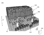
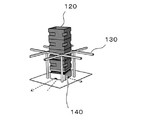
図1、図2及び図3を用いて、自動倉庫100のシステム構成の概要が説明される。図1は、自動倉庫100の内部の一例を概略的に示す。図2は、自動倉庫100のシステム構成の一例を概略的に示す。図3は、自動倉庫100におけるコンテナの保管方法の一例を概略的に示す。[Overview of Automated Warehouse 100]
An outline of the system configuration of the
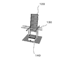
図1に示されるとおり、本実施形態において、自動倉庫100は、1以上のコンテナ120と、1以上のラック130とを備える。自動倉庫は、1以上の搬送車140を備えてもよい。自動倉庫100は、1以上のピッキング装置150を備えてもよい。自動倉庫100は、管理サーバ160を備えてもよい。図1及び図2に示されるとおり、本実施形態において、自動倉庫100の床10は、x−y平面上に配される。また、自動倉庫100の壁20は、床10からz方向に延伸する。本実施形態において、z方向に略平行な方向が上下方向と称される場合がある。
As shown in FIG. 1, in the present embodiment, the
本実施形態において、自動倉庫100は、1以上の物品を保管する。1以上の物品のそれぞれは、例えば、コンテナ120に収容された状態で保管される。物品の保管としては、搬入、保存、管理、搬出などが例示される。
In this embodiment, the
より具体的には、物品が自動倉庫100に搬入される場合、搬入対象となる物品は、まず、ピッキング装置150によりコンテナ120に収容される。次に、搬送車140が、コンテナ120を、管理サーバ160により指定されたラック130まで搬送する。その後、コンテナ120が、搬送車140からラック130に移載される。これにより、これにより、物品が自動倉庫100から搬入される。
More specifically, when the goods are carried into the
また、物品が自動倉庫100から搬出される場合、まず、管理サーバ160が、搬出対象となる物品を収容するコンテナ120の保管場所を特定する。管理サーバ160は、搬送車140を、コンテナ120が保管されたラック130まで移動させる。次に、上記のコンテナ120が、ラック130から搬送車140に移載される。搬送車140は、コンテナ120を、ピッキング装置150のピッキング位置まで搬送する。その後、搬出対象となる物品が、ピッキング装置150によりコンテナ120から取り出される。これにより、物品が自動倉庫100から搬出される。
When the goods are carried out from the
本実施形態によれば、自動倉庫100の床10の上に、複数のラック130が、マトリクス状に設置される。複数のラック130のそれぞれは、1以上のコンテナ120を支持することができるように構成される。複数のラック130のそれぞれは、例えば、一列に積み上げられた複数のコンテナ120を支持することができるように構成される。
According to the present embodiment, a plurality of
[ラック130の概要]
複数のラック130のそれぞれは、例えば、各ラックが所定の位置に設置された場合に、上下方向に積み上げられた複数のコンテナ120の一部を側方又は下方から支持することができるように構成される。例えば、図3に示されるとおり、コンテナ120の外側の側面には、複数の切欠部124が形成される。本実施形態によれば、複数の切欠部124のそれぞれの一部がラック130の一部に嵌め込まれるように配置されることで、ラック130が、コンテナ120を下方から支持する。これにより、ラック130の予め定められた支持位置において、コンテナ120の下方向の移動が抑制され、コンテナ120がラック130に保管され得る。[Overview of rack 130]
Each of the plurality of
一実施形態において、ラック130は、上下方向に積み上げられた複数のコンテナ120に含まれる単一のコンテナ120を、側方又は下方から支持可能に構成される。他の実施形態において、ラック130は、上下方向に積み上げられた複数のコンテナ120に含まれる少なくとも2つのコンテナ120を、側方又は下方から支持可能に構成される。
In one embodiment, the
ラック130は、上記の一部のコンテナ120の側面に力を作用させることで、上記の複数のコンテナ120を支持してよい。ラック130は、上記の一部のコンテナ120の側面に配された孔の内面又は凹凸に力を作用させることで、上記の複数のコンテナ120を支持してよい。ラック130は、上記の一部のコンテナ120の底面に力を作用させることで、上記の複数のコンテナ120を支持してよい。ラック130は、上記の一部のコンテナ120の側面及び底面に力を作用させることで、上記の複数のコンテナ120を支持してよい。
The
より具体的には、図2に示されるとおり、ラック130は、例えば、フレーム222と、フレームサポート224とを備える。ラック130は、複数のフレーム222を備えてよい。ラック130は、複数のフレームサポート224を備えてよい。また、ラック130は、1以上のワイヤ232と、1以上のワイヤーサポート234とを備えてよい。なお、ラック130は、フレーム222及びフレームサポート224の少なくとも一方の強度を補強するための補強部材(図示されていない。)を有してもよい。
More specifically, as shown in FIG. 2, the
また、図3に示されるとおり、フレーム222及びフレームサポート224は、例えば、ラック130が床10の上に配されたときに、ラック130の内部に空間322及び空間324が形成されるように構成される。本実施形態においては、ラック130の内部に、1つの空間322と、4つの空間324が形成される。空間322及び空間324は、コンテナ120の搬送経路の一部を構成してよい。
Further, as shown in FIG. 3, the
本実施形態において、空間322は、フレーム222の設置位置から床10の位置まで、床10に略垂直な方向に沿ってフレーム222を仮想的に移動させた場合に、フレーム222により形成される開口、又は、フレーム222に形成された開口が通過する領域であってよい。床10に略垂直な方向は、鉛直方向であってもよく、ラック130に支持された複数のコンテナ120が重力により転倒又は倒壊しない程度に、鉛直方向から傾いた方向であってもよい。空間322の上端部は、フレーム222により囲まれてよい。空間322の側面は、空間324により囲まれてよい。
In the present embodiment, the
本実施形態において、空間322の形状及び大きさは、コンテナ120の形状及び大きさに基づいて決定されてよい。空間322の形状及び大きさは、コンテナ120が、床10に略垂直な回転軸を中心として、空間322の内部で回転することができるように決定される。空間322の形状及び大きさは、コンテナ120が空間322の内部で回転することのできる角度が、予め定められた数値範囲を満たすように決定されてもよい。コンテナ120の回転は、搬送車140の回転又は旋回により実現されてよい。搬送車140が、コンテナ120の搭載される搭載面を略水平方向に回転させる回転機構を有する場合、コンテナ120の回転は、当該回転機構の動作により実現されてもよく、当該回転機構の動作及び搬送車140の回転又は旋回の組み合わせにより実現されてもよい。
In this embodiment, the shape and size of the
一実施形態において、空間322の形状及び大きさは、予め定められた個数のコンテナ120を搭載した搬送車140が、空間322の内部に進入した後、空間322の内部において、床10に略垂直な回転軸を中心として回転又は旋回することができるように決定される。他の実施形態において、空間322の形状及び大きさは、例えば、予め定められた個数のコンテナ120を搭載した搬送車140が、空間322の内部に進入した後、搬送車140に配された回転機構が、搬送車140に搭載されたコンテナ120を、床10に略垂直な回転軸を中心として回転させることができるように決定される。
In one embodiment, the shape and size of the
本実施形態において、形状及び空間322の大きさは、予め定められた個数のコンテナ120を搭載した搬送車140が、ラック130に支持されている1以上のコンテナ120と衝突することなく、空間322を通過することができるように決定されてよい。空間322の形状及び大きさは、空間322の内部に配されたコンテナ120が、上下方向に移動することができるように決定されてもよい。例えば、空間322の形状及び大きさは、上記のコンテナ120の位置及び姿勢の少なくとも一方が特定の条件を満たす場合に、上記のコンテナ120が、空間322の内部から空間322の外部に上昇したり、空間322の外部から空間322の内部に下降したりすることができるように決定される。
In the present embodiment, the shape and the size of the
本実施形態において、4つの空間324のそれぞれは、床10、フレーム222及びフレームサポート224により囲まれた領域であってよい。4つの空間324のそれぞれは、ラック130の外部と、空間322とを連通させる。
In this embodiment, each of the four
本実施形態において、空間324の形状及び大きさは、予め定められた個数のコンテナ120を搭載した搬送車140が、空間324を通過することができるように決定される。例えば、空間324の大きさは、予め定められた個数のコンテナ120を搭載した搬送車140が、空間324を通過して、ラック130の外部から空間322の内部にコンテナ120を搬入することができるように決定される。空間324の大きさは、予め定められた個数のコンテナ120を搭載した搬送車140が、空間324を通過して、空間322の内部からラック130の外部にコンテナ120を搬出することができるように決定されてもよい。
In the present embodiment, the shape and size of the
これにより、搬送車140は、マトリクス状に配された複数のラック130の下を自在に走行して、第1の位置と、第2の位置との間で、コンテナ120を搬送することができる。例えば、搬送車242は、ラック130と、ピッキング装置150との間で、少なくとも1つのコンテナ120を搬送する。搬送車242は、第1のラック130と、第2のラック130との間で、少なくとも1つのコンテナ120を搬送してもよい。
As a result, the
[コンテナ120の保管方法の概要]
本実施形態において、自動倉庫100は、複数のコンテナ120を、上下方向に積み上げて保管することができる。上下方向に一列に積み上げられた複数のコンテナ120は、例えば、ラック130により、床10から予め定められた高さに支持される。これにより、ラック130に支持されたコンテナ120の下方の空間が、他のコンテナ120の搬送経路として利用され得る。[Outline of storage method of container 120]
In the present embodiment, the
本実施形態において、自動倉庫100は、特定のラック130に支持される複数のコンテナ120を、(i)当該特定のラック130に先に保管されたコンテナ120ほど、当該特定のラック130において上方に配され、(ii)当該特定のラック130において下方に配されたコンテナ120ほど、当該特定のラック130から先に取り出されるように保管してよい。例えば、特定のラック130に新たに保管されるコンテナ120は、当該特定のラック130において一列に積み上げられた複数のコンテナ120の最下部に配される。また、特定のラック130において一列に積み上げられた複数のコンテナ120は、最下部に配されたコンテナ120から順番に取り出される。
In the present embodiment, the
なお、自動倉庫100においては、複数のラック130の間でコンテナ120を移動させることがある。そのため、上下方向に一列に積み上げられて、特定のラック130に保管される複数のコンテナ120において、時間的に先に自動倉庫100に入庫されたコンテナ120が、必ずしも、時間的に後に自動倉庫100に入庫されたコンテナ120よりも上方に配されないことに留意されたい。
In the
本実施形態において、コンテナ120が、ラック130及び搬送車140の間で移載される工程において、コンテナ120の位置及び姿勢の少なくとも一方が調整される。例えば、コンテナ120及びラック130の相対的な位置関係(相対位置と称される場合がある)、並びに、コンテナ120の基準面及びラック130の基準面とのなす角度の少なくとも一方が調整される。コンテナ120の基準面及びラック130の基準面とのなす角度は、例えば、略鉛直方向に延伸する回転軸を中心としてコンテナ120を回転させることで調整される。上記の回転軸は、コンテナ120の内部に配されてもよく、コンテナ120の外部に配されてもよい。
In the present embodiment, in the process of transferring the
コンテナ120の位置及び姿勢の少なくとも一方は、例えば、搬送車140の動作により調整される。搬送車140の動作としては、搬送車140の移動動作、コンテナ120の昇降動作、及び、コンテナ120の回転動作の少なくとも1つが例示される。
At least one of the positions and postures of the
一実施形態によれば、コンテナ120の位置及び姿勢の少なくとも一方は、搬送車140の移動により調整される。搬送車140の移動としては、並進移動、回転移動、旋回移動などが例示される。例えば、コンテナ120及びラック130の相対位置が、搬送車140の並進移動により調整される。また、コンテナ120の基準面及びラック130の基準面とのなす角度が、搬送車140の回転運動又は旋回運動により調整される。
According to one embodiment, at least one of the positions and orientations of the
他の実施形態によれば、搬送車140が、コンテナ120の搭載される搭載面を略水平方向に回転させる回転機構を有し、コンテナ120の位置及び姿勢の少なくとも一方は、当該回転機構の動作により調整される。上記の回転機構は、上記の搭載面を略鉛直方向に移動させる昇降装置に組み込まれていてもよく、当該昇降装置の下部に配されていてもよく、当該昇降装置及び当該搭載面の間に配されていてもよい。
According to another embodiment, the
さらに他の実施形態によれば、コンテナ120の位置及び姿勢の少なくとも一方は、搬送車140の移動と、上記の回転機構の動作とにより調整される。例えば、コンテナ120及びラック130の相対位置が、搬送車140の並進移動により調整される。また、コンテナ120の基準面及びラック130の基準面とのなす角度が、上記の回転機構の動作により調整される。コンテナ120の基準面及びラック130の基準面とのなす角度は、搬送車140の回転運動又は旋回運動と、上記の回転機構の動作との組み合わせにより調整されてもよい。
According to still another embodiment, at least one of the positions and postures of the
上述されたとおり、ラック130の形状及び大きさは、コンテナ120の位置及び姿勢の少なくとも一方が特定の条件を満たす場合に、コンテナ120が上下方向に自由に移動することができるように設計されている。そのため、コンテナ120の移載工程において、コンテナ120の位置及び姿勢の少なくとも一方が調整されることで、(i)ラック130がコンテナ120を支持し、コンテナ120の上下方向の移動がラック130により制限される状態と、(ii)ラック130がコンテナ120を支持せず、コンテナ120の上下方向の移動がラック130により制限されない状態とが切り替えられ得る。上記の状態の切り替えの詳細は後述される。
As mentioned above, the shape and size of the
本実施形態によれば、例えば、新たに保管されるコンテナ120の回転及び昇降が調整されることで、コンテナ120がラック130に格納される。また、既に保管されているコンテナ120の回転及び昇降が調整されることで、コンテナ120がラック130から取り出される。コンテナ120の格納手順及び取出手順の詳細は後述される。
According to the present embodiment, for example, the
[自動倉庫100の各部の概要]
[コンテナ120]
本実施形態において、1以上のコンテナ120のそれぞれは、1以上の物品を収容するために用いられる。コンテナ120の材質、形状及び大きさは、例えば、物品の保管効率及びハンドリングの容易性を考慮して決定される。コンテナ120の形状及び大きさは、特に制限されるものではないが、例えば、幅が20cm〜1mであり、高さが20cm〜1mであり、奥行が20cm〜1mである。コンテナ120の詳細は後述される。[Overview of each part of the automated warehouse 100]
[Container 120]
In this embodiment, each of one or
[ラック130]
本実施形態において、1以上のラック130のそれぞれは、1以上のコンテナ120を支持する。例えば、ラック130は、一列に積み上げられた複数のコンテナ120を支持する。[Rack 130]
In this embodiment, each of the one or
一実施形態において、ラック130は、一列に積み上げられた複数のコンテナ120のうち、最下部に位置するコンテナ120を下方から支持する。これにより、ラック130は、一列に積み上げられた複数のコンテナ120の全てを支持することができる。
In one embodiment, the
他の実施形態において、一のコンテナ120の下部と、他のコンテナ120の上部とが連結可能又は着脱可能に構成されている場合、ラック130は、一列に積み上げられた複数のコンテナ120のうち、任意の位置に配されたコンテナ120を下方から支持してよい。これにより、ラック130は、一列に積み上げられた複数のコンテナ120の全てを支持することができる。
In another embodiment, when the lower part of one
上記の2つの実施形態において、ラック130は、一列に積み上げられた複数のコンテナ120の一部を構成する2以上のコンテナ120を下方から支持してもよい。これにより、ラック130は、一列に積み上げられた複数のコンテナ120の全てを支持することができる。
In the above two embodiments, the
本実施形態において、複数のラック130のそれぞれは、1以上のコンテナ120を、床10の上方の位置で支持する。図2に示されるとおり、例えば、床10と、ラック130に支持された1以上のコンテナ120のうち、最下部に配されたコンテナ120の底面との距離H22は、床10と、搬送車140に搭載された少なくとも1つのコンテナ120のうち、最上部に配されたコンテナ120の上面との距離H24よりも大きい。これにより、1以上の搬送車140のそれぞれは、少なくとも1つのコンテナ120を搭載した状態で、1以上のラック130により支持された複数のコンテナの下方を走行することができる。
In this embodiment, each of the plurality of
(フレーム222)
本実施形態において、ラック130のフレーム222は、コンテナ120の外側の一部を下方から支持することで、コンテナ120を所定の位置に支持する。フレーム222は、コンテナ120の外側の底面の一部を下方から支持してもよく、コンテナ120の外側の側面の一部を下方から支持してもよい。フレーム222は、コンテナ120を少なくとも2点で支持してよい。フレーム222は、コンテナ120を3点で支持してもよく、4点で支持してもよい。フレーム222は、コンテナ120を5点以上の位置で支持してもよい。(Frame 222)
In the present embodiment, the
上述されたとおり、予め定められた個数のコンテナ120を搭載した搬送車140は、空間324を介して、ラック130の外部と、空間322の内部との間で、上記のコンテナ120を移動させることができる。そこで、本実施形態において、ラック130のフレーム222は、ラック130に支持される1以上のコンテナ120の最下部に位置するコンテナ120が、ラック130の外部及び空間322の間における、少なくとも1つのコンテナ120の移動を制限しないような位置に配される。
As described above, the
これにより、上記の距離H22が、上記の距離H24よりも大きくなる。また、ラック130のフレーム222は、ラック130がコンテナ120を支持している場合であっても、少なくとも1つのコンテナ120を搭載した1以上の搬送車140の少なくとも1つが、ラック130に支持される1以上のコンテナ120の最下部に位置するコンテナ120の下方を走行することができる。
As a result, the above-mentioned distance H22 becomes larger than the above-mentioned distance H24. Further, in the
一実施形態において、フレーム222及び床10の距離は、フレーム222が、ラック130により支持される1以上のコンテナ120のうち、最下部に位置するコンテナ120を支持する場合に、予め定められた第1の個数のコンテナ120を搭載した搬送車140が、ラック130により支持される1以上のコンテナ120の下方を走行することができるように決定される。他の実施形態において、フレーム222及び床10との距離は、フレーム222が直接支持するコンテナ120の下方に、予め定められた第2の個数のコンテナ120が連結されている場合に、予め定められた第1の個数のコンテナ120を搭載した搬送車140が、ラック130により支持される1以上のコンテナ120の下方を走行することができるように決定される。
In one embodiment, the distance between the
さらに他の実施形態において、フレーム222及び床10の距離が、動的に変更されてよい。例えば、フレームサポート224に配されたアクチュエータ(図示されていない。)により、フレーム222の上下方向の位置が変更される。これにより、ラック130のフレーム222、又は、ラック130に支持されたコンテナ120と、搬送車140に搭載されたコンテナとの衝突が防止される。
In yet another embodiment, the distance between the
上述されたとおり、コンテナ120の移載工程において、コンテナ120の位置及び姿勢の少なくとも一方が調整されることで、(i)ラック130がコンテナ120を支持し、コンテナ120の上下方向の移動がラック130により制限される状態と、(ii)ラック130がコンテナ120を支持せず、コンテナ120の上下方向の移動がラック130により制限されない状態とが切り替えられ得る。本実施形態によれば、フレーム222の位置及び姿勢がフレームサポート224により固定された状態で、搬送車140がコンテナ120の位置及び姿勢の少なくとも一方を調整することで、(i)コンテナ120の上下方向の移動がフレーム222により制限される状態と、(ii)コンテナ120の上下方向の移動がフレーム222により制限されない状態とが切り替えられる。
As described above, in the transfer process of the
本実施形態において、フレーム222は、コンテナ120の基準面126と、フレームサポート224の基準面226とのなす角度が予め定められた条件を満足する場合に、空間322の内部に配されたコンテナ120の上下方向の移動を制限する位置に配される。この場合、例えば、フレーム222がコンテナ120の下方向の移動にとって障害となることで、コンテナ120がラック130に支持される。
In the present embodiment, the
また、フレーム222は、基準面126及び基準面226のなす角度が予め定められた条件を満足しない場合に、空間322の内部に配されたコンテナ120の上下方向の移動を制限しない位置に配される。この場合、フレーム222がコンテナ120の上下方向の移動にとって障害とならないので、空間322の内部に配されたコンテナ120は、上下方向に自由に移動することができる。
Further, the
基準面126及び基準面226のなす角度は、基準面126の法線ベクトルの始点と、基準面226の法線ベクトルの始点とを重ねた場合に当該2つの法線ベクトルにより形成される角度のうち、0度以上180度以下となる方の角度であってよい。予め定められた条件は、基準面126及び基準面226のなす角度が、予め定められた数値範囲の範囲内であるという条件であってよい。上記の数値範囲は、上限値のみが決定されていてもよく、下限値のみが決定されていてもよく、上限値及び下限値が決定されていてもよい。
The angle formed by the
上記の数値範囲は、例えば、コンテナ120の外観形状及び大きさ、ラック130の外観形状及び大きさ、コンテナ120の積込時間及び取出時間の少なくとも一方に関する目標値、耐震性能の目標値、コンテナ120をラック130に格納する際の位置決め精度の目標値、並びに、コンテナ120の有効利用の程度の目標値の少なくとも1つに基づいて決定される。耐震性能は、ラック130が、上下方向に積み上げられた予め定められた個数のコンテナ120を倒壊させることなく支持することのできる地震の規模として定義されてよい。地震の規模としては、当該地震の震度又は最大加速度が例示される。
The above numerical ranges include, for example, the external shape and size of the
コンテナ120の有効利用の程度は、コンテナ120の収容スペースの体積(Vsと称される場合がある。)と、収容スペースの内部に形成されたデッドスペースの体積(Vdと称される場合がある。)とに基づいて決定されてよい。コンテナ120の有効利用の程度が大きい程、Vsに対するVdの割合が小さくなる。コンテナ120の有効利用の程度は、例えば、Vs/(Vs+Vd)、又は、Vs/Vdとして定義されてもよい。
The degree of effective utilization of the
上記の数値範囲は、上記の積込時間及び取出時間の少なくとも一方に関する目標値が大きい程、上記の数値範囲の上限値が大きくなるように決定されてよい。上記の数値範囲は、耐震性能の目標値が大きい程、上記の数値範囲の下限値が大きくなるように決定されてよい。上記の数値範囲は、上記の位置決め精度の目標値が大きい程、上記の数値範囲の幅が狭くなるように決定されてよい。 The numerical range may be determined so that the larger the target value for at least one of the loading time and the taking-out time, the larger the upper limit of the numerical range. The above numerical range may be determined so that the larger the target value of seismic performance, the larger the lower limit of the above numerical range. The numerical range may be determined so that the larger the target value of the positioning accuracy is, the narrower the width of the numerical range is.
例えば、コンテナ120の側面の延伸方向(軸方向と称される場合がある。)におけるコンテナ120の断面形状の外接円の直径の変動が大きい程、上記の角度が小さくても、十分な耐震性能を確保することができる。また、コンテナ120がラック130に支持された状態において、コンテナ120及びラック130の接触面積が大きいほど、耐震性能が向上する。例えば、図3に示された実施形態によれば、上記の角度が大きい程、コンテナ120及びラック130の接触面積が大きくなる。
For example, the greater the variation in the diameter of the circumscribed circle of the cross-sectional shape of the
コンテナ120の回転速度が一定であれば、上記の角度が小さい程、コンテナ120の積込時間及び取出時間を短縮することができる。また、コンテナ120の積込時間及び取出時間の目標値が一定であれば、上記の角度が小さい程、コンテナ120の回転速度を小さくすることができる。コンテナ120の回転速度が小さい程、コンテナ120の積込時又は取出時におけるコンテナ120の倒壊が抑制される。
If the rotation speed of the
コンテナ120の軸方向は、コンテナ120の底面に略垂直な方向、又は、コンテナ120の底面から開口に向かう方向であってよい。コンテナ120の軸方向は、コンテナ120の収容スペースの深さ方向であってもよく、コンテナ120がラック130に保管される状態における上下方向であってもよい。
The axial direction of the
コンテナ120の基準面126は、コンテナ120がラック130に保管される場合に、床10と略垂直に配される面であることが好ましい。コンテナ120の基準面126は、コンテナ120がラック130に保管される場合に、基準面126の法線ベクトル及び鉛直方向のなす角度が約90度となる面であってもよい。ラック130の基準面226は、ラック130が床10の上に設置された場合に、床10と略垂直に配される面であることが好ましい。ラック130の基準面226は、ラック130が床10の上に設置された場合に、基準面226の法線ベクトル及び鉛直方向のなす角度が約90度となる面であってもよい。
The
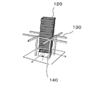
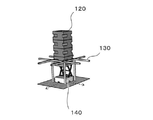
図3に示されるとおり、本実施形態において、フレーム222は、4本の梁部材を有する。本実施形態において、4本の梁部材のそれぞれは、2本のフレームサポート224に支持される。4本の梁部材のそれぞれは、当該梁部材の延伸方向と、当該2本のフレームサポート224の延伸方向とが略垂直になるように配されてよい。また、上述されたとおり、4本の梁部材のそれぞれは、当該梁部材の下端及び設置面の距離が、予め定められた個数のコンテナ120を搭載した搬送車140の通行に必要とされる高さよりも大きくなる位置に配されてよい。
As shown in FIG. 3, in this embodiment, the
図3に示されるとおり、フレーム222、又は、フレーム222を構成する梁部材の高さHFは、コンテナ120の切欠部124の高さより小さくてよい。これにより、複数の切欠部124のそれぞれの一部がラック130に嵌め込まれ得る。その結果、上下方向の振動又は水平方向の振動によるコンテナ120の転倒又は倒壊が抑制され得る。
As shown in FIG. 3, the height HF of the
(フレームサポート224)
本実施形態において、ラック130のフレームサポート224は、フレーム222と、床10との間に配される。フレームサポート224は、フレーム222が受けた1以上のコンテナ120の荷重を、床10に伝達する。フレームサポート224は、フレーム222を、上述された所定の高さに配置する。(Frame support 224)
In this embodiment, the
図3に示されたとおり、本実施形態において、ラック130は、4本のフレームサポート224を有する。4本のフレームサポート224のそれぞれは、柱状形状を有してよい。4本のフレームサポート224のそれぞれは、一方の端部が床10に接触するように配されてよい。
As shown in FIG. 3, in this embodiment, the
4本のフレームサポート224の配置は、例えば、床10の表面において、4本のフレームサポート224に外接する四角形の対角線の長さが、コンテナ120の第1外接円の直径、又は、搬送車140の最小回転直径よりも大きくなるように決定される。第1外接円及び最小回転直径の詳細は後述される。
In the arrangement of the four frame supports 224, for example, on the surface of the
4本のフレームサポート224の配置は、上記の四角形の各辺の長さが、コンテナ120の第1外接円の直径、又は、搬送車140の最小回転直径よりも小さくなるように決定されてよい。4本のフレームサポート224の配置は、上記の四角形の各辺の長さの最大値が、コンテナ120を搭載した搬送車140の通行に必要とされる幅よりも大きくなるように決定されてよい。
The arrangement of the four frame supports 224 may be determined so that the length of each side of the above rectangle is smaller than the diameter of the first circumscribed circle of the
コンテナ120の第1外接円は、コンテナ120の開口を上にして、コンテナ120の底面が水平となるように配置し、コンテナ120の外周を、コンテナ120の切欠部124の上端を通る水平面で切断して得られる断面形状(第1断面形状と称される場合がある。)に外接する円であっってよい。搬送車140の最小回転直径は、搬送車140が、舵取り車輪を最大に操作して旋回した場合、又は、搬送車140が、床10に略垂直な軸を中心として、その場で回転した場合に、搬送車140の最外側に位置する部位が描く円の直径であってよい。上記の床10の表面は、略平面であってよい。
The first circumscribed circle of the
(ワイヤ232)
本実施形態において、ラック130のワイヤ232は、フレーム222よりも上方に配される。ラック130は、複数のワイヤ232を有してもよい。複数のワイヤ232が、マトリックス状に配された複数のラック130の各列又は各行の上方に配されてもよい。複数のワイヤ232が、複数のワイヤ232が、マトリックス状に配された複数のラック130の複数の列の一部又は複数の行の一部の上方に配されてもよい。1又は複数のワイヤ232が、マトリックス状に配された複数のラック130の外周の上方を囲うように配されてよい。これにより、ラック130に支持された1以上のコンテナ120の転倒又は倒壊が抑制され得る。(Wire 232)
In this embodiment, the
マトリックス状に配された複数のラック130の同一の列又は行の上方に、設置される高さの異なる複数のワイヤ232が配されてもよい。これにより、ラック130に支持された1以上のコンテナ120の転倒又は倒壊がさらに抑制され得る。
A plurality of
(ワイヤーサポート234)
本実施形態において、ラック130のワイヤーサポート234は、1又は複数のワイヤ232を支持する。ワイヤーサポート234は、1又は複数のワイヤ232を所定の高さに配置する。ラック130は、複数のワイヤーサポート234を有してもよい。これにより、ラック130に支持された1以上のコンテナ120の転倒又は倒壊が抑制され得る。(Wire support 234)
In this embodiment, the
[搬送車140]
本実施形態において、搬送車140は、第1の位置と、第2の位置との間で、少なくとも1つのコンテナ120を搬送する。第1の位置及び第2の位置は、自動倉庫100の内部の異なる位置であってよい。本実施形態において、搬送車140は、ラック130との間でコンテナ120を移載する。一実施形態において、搬送車140は、ラック130にコンテナ120を積み込む。他の実施形態において、搬送車140は、ラック130からコンテナ120を取り出す。[Transport vehicle 140]
In the present embodiment, the
本実施形態において、搬送車140は、コンテナ120を上下方向に移動させることができる。例えば、搬送車140は、ラック130の下を走行するときには、コンテナ120を比較的低い位置(走行位置と称される場合がある。)に維持する。一方、搬送車140は、コンテナ120をラック130に積み込んだり、ラック130からコンテナ120を取り出したりするときには、コンテナ120を上下に移動させる。
In the present embodiment, the
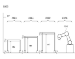
図2に示されるとおり、搬送車140は、ラック130及びピッキング装置150の間でコンテナ120を搬送する搬送車242と、ピッキング装置150から、自動倉庫100の内部又は外部の他の場所に、コンテナ120を搬送する搬送車244とを含んでよい。搬送車242及び搬送車244は、同一の構成を有してもよく、異なる構成を有してもよい。搬送車140の詳細は後述される。
As shown in FIG. 2, the
[ピッキング装置150]
本実施形態において、ピッキング装置150は、一のコンテナ120と、他のコンテナ120との間で、物品を移載する。一実施形態において、ピッキング装置150は、搬送車242に搭載されたコンテナ120に収容されている物品を取り出し、当該物品を、搬送車244に搭載されたコンテナ120に収容する。他の実施形態において、ピッキング装置150は、搬送車244に搭載されたコンテナ120に収容されている物品を取り出し、当該物品を、搬送車242に搭載されたコンテナ120に収容する。[Picking device 150]
In the present embodiment, the
[管理サーバ160]
本実施形態において、管理サーバ160は、物品の保管状況を管理する。管理サーバ160は、自動倉庫100の各部を管理してもよい。例えば、管理サーバ160は、自動倉庫100の各部の状態を管理する。管理サーバ160は、管理サーバ160は、1以上の搬送車140のそれぞれの運転を管理してもよい。管理サーバ160は、1以上のラック130のそれぞれの運転を管理してもよい。[Management server 160]
In the present embodiment, the
床10は、設置面の一例であってよい。自動倉庫100は保管システムの一例であってよい。コンテナ120は、1以上のコンテナの一例であってよい。コンテナ120は、少なくとも1つのコンテナの一例であってよい。コンテナ120は、第1コンテナ、第2コンテナ又は第3コンテナの一例であってよい。切欠部124の上面は、第1領域の一部であってよい。切欠部124の側面は、第2領域の一部であってよい。基準面126は、1以上のコンテナの側面部材の基準面の一例であってよい。ラック130は、架台の一例であってよい。搬送車140は、搬送ロボットの一例であってよい。管理サーバ160は、運転管理部の一例であってよい。
The
フレーム222は、支持部及び梁部材の一例であってよい。フレーム222は、複数の支持部の一例であってよい。フレーム222を構成する複数の梁部材のそれぞれは、支持部の一例であってよい。フレームサポート224は、基礎部及び支柱部材の一例であってよい。基準面226は、架台の基準面の一例であってよい。基準面226は、複数の基礎部の少なくとも1つの基準面の一例であってよい。ワイヤ232は、転倒防止部材の一例であってよい。ワイヤーサポート234は、転倒防止部材の一例であってよい。搬送車242は、搬送ロボットの一例であってよい。搬送車244は、搬送ロボットの一例であってよい。空間322は、昇降空間の一例であってよい。
The
本実施形態においては、フレーム222が、4本の梁部材により構成される場合を例として、フレーム222の詳細が説明された。しかしながら、フレーム222は本実施形態に限定されない。他の実施形態において、フレーム222は、開口を有する板状部材であってよい。
In the present embodiment, the details of the
本実施形態においては、フレーム222を構成する各梁部材の外観形状が、四角柱状である場合を例として、ラック130の詳細が説明された。しかしながら、梁部材の外観形状は、四角柱状に限定されない。他の実施形態において、梁部材の外観形状は、任意の断面形状を有する柱状であってよい。梁部材の断面形状は直線により構成されてもよく、梁部材の断面形状の少なくとも一部に曲線が含まれてもよい。梁部材の断面形状が多角形である場合、当該多角形の全ての内角が略直角であってもよく、当該多角形の内角の少なくとも一部が鋭角であってもよい。梁部材の断面形状が多角形であり、当該多角形の全ての内角が略直角である場合、例えば、フレーム222の上面に段差が形成される。例えば、梁部材の断面形状はL字型である場合、フレーム222の上面に段差が形成される。梁部材の断面形状が多角形であり、当該多角形の内角の少なくとも一部が鋭角である場合、例えば、フレーム222の上面に斜面が形成される。
In the present embodiment, the details of the
本実施形態においては、フレーム222がコンテナ120の切欠部124に嵌め込まれるようにして、フレーム222がコンテナ120を下方から支持する場合を例として、ラック130の詳細が説明された。しかしながら、ラック130は本実施形態に限定されない。他の実施形態において、フレーム222は、コンテナ120の側面からコンテナ120の外側に向かって突出する突出部を下方から支持してもよい。上記の突出部は、コンテナ120の上端近傍に配さ手もよく、コンテナ120の下端近傍に配されてもよく、コンテナ120の上端及下端中間部分に配されてもよい。なお、切欠部124を構成する面のうち、フレーム222と接触する面は、上記の突出部の一例であってよい。
In the present embodiment, the details of the
本実施形態においては、フレーム222が、コンテナ120を下方から支持する場合を例として、ラック130の詳細が説明された。しかしながら、ラック130は本実施形態に限定されない。他の実施形態において、コンテナ120の基準面126と、フレームサポート224の基準面226とのなす角度が予め定められた条件を満足する場合に、2本以上のフレームサポート224のそれぞれに形成された凹部に、コンテナ120の外周に配された1又は複数の凸部の少なくとも一部が入り込み、フレームサポート224の凹部がコンテナ120の凸部を下方から支持することで、ラック130がコンテナ120を支持する。なお、この場合、ラック130は、梁部材として機能するフレーム222を有してもよく、フレーム222を有しなくてもよい。
In the present embodiment, the details of the
本実施形態においては、マトリックス状に配された複数のラック130の下に、コンテナ120の搬送経路がグリッド状に形成される場合を例として、コンテナ120の搬送経路の詳細が説明された。しかしながら、コンテナ120の搬送経路の形状は、本実施形態に限定されない。他の実施形態において、列状に配された複数のラック130の下に、ライン状の搬送経路が形成されてもよく、マトリックス状に配された複数のラック130の下に、複数個のライン状の搬送経路が形成されてもよい。
In the present embodiment, the details of the transport path of the
[自動倉庫100の各部の具体的な構成]
自動倉庫100の各部は、ハードウエアにより実現されてもよく、ソフトウエアにより実現されてもよく、ハードウエア及びソフトウエアにより実現されてもよい。自動倉庫100の各部は、その少なくとも一部が、単一のサーバによって実現されてもよく、複数のサーバによって実現されてもよい。自動倉庫100の各部は、その少なくとも一部が、仮想サーバ上又はクラウドシステム上で実現されてもよい。[Specific configuration of each part of the automated warehouse 100]
Each part of the
自動倉庫100の各部は、その少なくとも一部が、パーソナルコンピュータ又は携帯端末によって実現されてもよい。携帯端末としては、携帯電話、スマートフォン、PDA、タブレット、ノートブック・コンピュータ又はラップトップ・コンピュータ、ウエアラブル・コンピュータなどを例示することができる。自動倉庫100の各部は、ブロックチェーンなどの分散型台帳技術又は分散型ネットワークを利用して、情報を格納してもよい。
At least a part of each part of the
自動倉庫100を構成する構成要素の少なくとも一部がソフトウエアにより実現される場合、当該ソフトウエアにより実現される構成要素は、一般的な構成の情報処理装置において、当該構成要素に関する動作を規定したプログラムを起動することにより実現されてよい。上記の一般的な構成の情報処理装置は、(i)CPU、GPUなどのプロセッサ、ROM、RAM、通信インタフェースなどを有するデータ処理装置と、(ii)キーボード、ポインティングデバイス、タッチパネル、カメラ、音声入力装置、ジェスチャ入力装置、各種センサ、GPS受信機などの入力装置と、(iii)表示装置、音声出力装置、振動装置などの出力装置と、(iv)メモリ、HDD、SSDなどの記憶装置(外部記憶装置を含む。)とを備えてよい。
When at least a part of the components constituting the
上記の一般的な構成の情報処理装置において、上記のデータ処理装置又は記憶装置は、上記のプログラムを記憶してよい。上記のプログラムは、プロセッサによって実行されることにより、上記の情報処理装置に、当該プログラムによって規定された動作を実行させる。上記のプログラムは、非一時的なコンピュータ可読記録媒体に格納されていてもよい。上記のプログラムは、CD−ROM、DVD−ROM、メモリ、ハードディスクなどのコンピュータ読み取り可能な媒体に記憶されていてもよく、ネットワークに接続された記憶装置に記憶されていてもよい。 In the information processing apparatus having the above general configuration, the data processing apparatus or the storage apparatus may store the above program. The above program is executed by the processor to cause the above information processing apparatus to execute the operation specified by the program. The above program may be stored on a non-temporary computer-readable recording medium. The above program may be stored in a computer-readable medium such as a CD-ROM, a DVD-ROM, a memory, or a hard disk, or may be stored in a storage device connected to a network.
上記のプログラムは、コンピュータを、自動倉庫100又はその一部として機能させるためのプログラムであってよい。上記のプログラムは、自動倉庫100の各部の動作を規定したモジュールを備えてよい。これらのプログラム又はモジュールは、データ処理装置、入力装置、出力装置、記憶装置等に働きかけて、コンピュータを自動倉庫100の各部として機能させたり、コンピュータに自動倉庫100の各部における情報処理方法を実行させたりする。
The above program may be a program for operating the computer as the
上記のプログラムは、コンピュータ読み取り可能な媒体又はネットワークに接続された記憶装置から、自動倉庫100の少なくとも一部を構成するコンピュータにインストールされてよい。上記のプログラムが実行されることにより、コンピュータが、自動倉庫100の各部の少なくとも一部として機能してもよい。上記のプログラムに記述された情報処理は、当該プログラムがコンピュータに読み込まれることにより、当該プログラムに関連するソフトウエアと、自動倉庫100又はその一部の各種のハードウエア資源とが協働した具体的手段として機能する。そして、上記の具体的手段が、本実施形態におけるコンピュータの使用目的に応じた情報の演算又は加工を実現することにより、当該使用目的に応じた自動倉庫100が構築される。
The above program may be installed on a computer constituting at least a part of the
上記のプログラムは、コンピュータに、自動倉庫100又はその一部における情報処理方法を実行させるためのプログラムであってよい。上記の情報処理方法は、ラック130の動作を制御する方法であってよい。上記の情報処理方法は、ラック130のフレーム222が設置される位置を調整する方法であってよい。上記の情報処理方法は、搬送車140の動作を制御する方法であってよい。上記の情報処理方法は、搬送車140が、コンテナ120をラック130に積み込む方法であってよい。上記の情報処理方法は、搬送車140が、コンテナ120をラック130からコンテナ120を取り出す方法であってもよい。上記の情報処理方法は、管理サーバ160が、ラック130及び搬送車140の少なくとも一方を制御する方法であってもよい。
The above program may be a program for causing a computer to execute an information processing method in the
上記の情報処理方法は、少なくとも1つの前記コンテナを搭載可能な搭載部と、前記搭載部を上下方向に移動させる昇降部と、前記搬送ロボットを移動させる移動部とを備える搬送ロボットの動作を制御する制御方法であってよい。上記の制御方法は、例えば、移動部が搬送ロボットを移動させて、架台の昇降空間の内部にコンテナを搬送する手順を有する。上記の制御方法は、例えば、移動部が搬送ロボットを移動させて、コンテナの基準面と、架台の基準面とのなす角度が、予め定められた条件を満足しないように、コンテナの位置を調整する手順を有する。上記の制御方法は、例えば、昇降部が搭載部を上方に移動させて、コンテナの第1領域の下端を、架台の複数の支持部の上端よりも上方に配置する手順を有する。上記の制御方法は、例えば、移動部が搬送ロボットを移動させて、コンテナの基準面と、架台の基準面とのなす角度が、予め定められた条件を満足するように、コンテナの位置を調整する手順を有する。 The above information processing method controls the operation of a transfer robot including a mounting unit on which at least one of the containers can be mounted, an elevating unit for moving the mounting unit in the vertical direction, and a moving unit for moving the transport robot. It may be a control method. The above-mentioned control method includes, for example, a procedure in which a moving unit moves a transfer robot to transfer a container inside an elevating space of a gantry. In the above control method, for example, the moving unit moves the transfer robot to adjust the position of the container so that the angle between the reference surface of the container and the reference surface of the gantry does not satisfy a predetermined condition. Have a procedure to do. The above control method includes, for example, a procedure in which the elevating portion moves the mounting portion upward so that the lower end of the first region of the container is arranged above the upper ends of the plurality of support portions of the gantry. In the above control method, for example, the moving unit moves the transfer robot and adjusts the position of the container so that the angle between the reference surface of the container and the reference surface of the gantry satisfies a predetermined condition. Have a procedure to do.
上記の制御方法は、移動部が、搬送ロボットを、架台の昇降空間の内部に移動させる手順を含んでよい。移動部が搬送ロボットを移動させて、搭載部、又は、搭載部に搭載された少なくとも1つのコンテナの最上部に位置するコンテナの位置を、架台に支持されているコンテナの下方の特定の位置に調整する手順を含んでよい。昇降部が搭載部を上方に移動させて、搭載部、又は、搭載部に搭載された少なくとも1つのコンテナの最上部に位置するコンテナが、架台に支持されているコンテナを支持する手順を含んでよい。移動部が搬送ロボットを移動させて、第1コンテナの基準面と、架台の基準面とのなす角度が、予め定められた条件を満足しないように、コンテナの位置を調整する手順を含んでよい。昇降部が搭載部を下方に移動させて、架台に支持されているコンテナの第1領域の上端が、架台の複数の支持部の下端よりも下方に配置する手順を含んでよい。 The above control method may include a procedure in which the moving unit moves the transfer robot inside the elevating space of the gantry. The moving part moves the transfer robot to move the position of the container located at the top of the mounting part or at least one container mounted on the mounting part to a specific position below the container supported by the gantry. It may include a procedure for adjustment. The elevating part moves the mounting part upward, and the container located at the top of the mounting part or at least one container mounted on the mounting part includes a procedure for supporting the container supported by the gantry. good. The moving unit may include a procedure for moving the transfer robot to adjust the position of the container so that the angle formed by the reference surface of the first container and the reference surface of the gantry does not satisfy a predetermined condition. .. It may include a procedure in which the elevating part moves the mounting part downward so that the upper end of the first region of the container supported by the gantry is positioned below the lower ends of the plurality of support parts of the gantry.
図4、図5、図6、図7及び図8を用いて、一実施形態に係るコンテナ120の詳細が説明される。また、図6、図7及び図8を用いて、コンテナ120の外観形状及びラック130の外観形状の関係が説明される。
The details of the
図4は、コンテナ120の一例を概略的に示す。図5は、コンテナ120のA−A'断面における断面形状の一例を概略的に示す。図6は、コンテナ120のB−B'断面における断面形状の一例を概略的に示す。図7は、コンテナ120のC−C'断面における断面形状の一例を概略的に示す。図8は、コンテナ120と、ワイヤ232との位置関係の一例を概略的に示す。
FIG. 4 schematically shows an example of the
図4に示されるとおり、本実施形態において、コンテナ120は、底板422と、側壁424と、カバー430とを備える。これにより、コンテナ120の内部に、物品が収容される収容スペース440が形成される。また、本実施形態において、側壁424の外側には、複数の切欠部124が配される。側壁424の一部は、コンテナ120の基準面126として用いられる。
As shown in FIG. 4, in the present embodiment, the
本実施形態において、底板422は、側壁424の一方の端部に形成された開口を塞ぐ。底板422の一部は、コンテナ120の側面の一部を構成してよい。本実施形態において、側壁424は、少なくとも一部に中空柱状の形状を有する。側壁424は、底板422の一方の面の側に延伸するように配される。側壁424の延伸方向(軸方向と称される場合がある。)は、底板422の少なくとも一部に配された平面の法線方向と略平行であってよい。
In this embodiment, the
本実施形態において、カバー430は、切欠部124の外形を構成する。本実施形態において、カバー430は、側壁424の内側の面から、コンテナ120の内側に向かって突出するように配される。本実施形態において、カバー430は、例えば、切欠部124の上面を構成する部材と、切欠部124の下面を構成する部材と、切欠部124の側面を構成する部材とを有する。切欠部124の上面を構成する部材、切欠部124の下面を構成する部材、及び、切欠部124の側面を構成する部材のそれぞれは、平面部材であってもよく、曲面部材であってもよく、平面部材及び曲面部材の組み合わせであってもよい。
In this embodiment, the
切欠部124の上面を構成する部材の形状は、フレーム222の上面の形状に合致するように構成されてよい。例えば、フレーム222の上面が平面である場合、切欠部124の上面を構成する部材は、平板であってよい。フレーム222の上面に凸部及び凹部の少なくとも一方が配される場合、切欠部124の上面を構成する部材は、フレーム222の凸部に対応する凹部、及び、フレーム222の凹部に対応する凸部の少なくとも一方を有してよい。
The shape of the member constituting the upper surface of the
図5に示されるとおり、本実施形態において、側壁424の下端512は、底板422に接する。側壁424の上端514は、コンテナ120の開口を構成する。本実施形態において、底板422の外側には、凸部522が配される。凸部522の形状及び大きさは、コンテナ120の開口の形状及び大きさに基づいて決定されてよい。
As shown in FIG. 5, in the present embodiment, the
例えば、凸部522の大きさは、コンテナ120の開口の大きさよりも小さい。この場合、コンテナ120の下端における、コンテナ120の底面の外縁から凸部522までの距離WLは、コンテナ120の上端におけるコンテナ120の側面の外縁から開口までの距離WUより小さくなる。これにより、2つのコンテナ120が上下に積み上げられる場合に、上方のコンテナ120の凸部522が、下方のコンテナ120の開口に嵌め込まれる。その結果、コンテナ120の転倒又は倒壊が抑制され得る。
For example, the size of the
本実施形態において、側壁424は、側壁424の軸方向に沿って、領域542と、領域544と、領域546とを有する。領域542、領域544、及び、領域546のそれぞれは、側壁424の軸方向に延伸する領域であってよい。領域542は、領域544に隣接して配される。領域544は、領域542及び領域546に隣接して配される。本実施形態において、領域542は、領域544よりも底板422に近い位置に配される。領域546は、領域544よりも底板422から遠い位置に配される。
In this embodiment, the
本実施形態において、領域544には、切欠部124が形成される。領域544には、コンテナ120がラック130に支持される場合に、ラック130に接触する面552が形成される。これにより、ラック130は、コンテナ120の面552を下方から支持することで、コンテナ120を所定の高さに保持することができる。
In the present embodiment, the
領域544の高さHD(切欠部124の高さと称される場合がある)は、図3に示されるフレーム222の高さHFより大きくてよい。これにより、複数の切欠部124のそれぞれの一部がラック130に嵌め込まれ得る。その結果、上下方向の振動又は水平方向の振動によるコンテナ120の転倒又は倒壊が抑制され得る。
The height HD of the region 544 (sometimes referred to as the height of the notch 124) may be greater than the height HF of the
図6は、側壁424の領域546を、側壁424の軸方向に略垂直な平面で切断した場合の断面図の一例であってよい。図6は、領域546における側壁424の断面形状を、ラック130とともに示す。図6は、コンテナ120の基準面126と、ラック130の基準面226とのなす角度が予め定められた数値範囲の範囲外であり、ラック130がコンテナ120の上下方向の移動を制限しない状態における、コンテナ120の外形と、ラック130の外形との関係を示す。なお、本実施形態において、領域542における側壁424の断面形状は、領域546における側壁424の断面形状と同様の形状を有する。
FIG. 6 may be an example of a cross-sectional view when the
図6に示されるとおり、本実施形態によれば、フレーム222の内側の面により、開口が形成される。本実施形態において、フレーム222の開口は、長辺の長さがLXであり、短辺の長さがLYである長方形の断面形状を有する。
As shown in FIG. 6, according to the present embodiment, an opening is formed by the inner surface of the
なお、本実施形態においては、説明を簡単にすることを目的として、フレーム222の開口の断面形状が長方形である場合を例として、コンテナ120及びラック130の関係が説明される。しかしながら、開口の断面形状は本実施形態に限定されない。他の実施形態において、開口の断面形状は、正方形であってもよく、四角形以外の多角形であってもよく、曲線形状を含んでもよい。四角形の長辺は、多角形の辺のうち最も長い辺の一例であってよい。
In this embodiment, for the purpose of simplifying the explanation, the relationship between the
図6に示されるとおり、本実施形態において、コンテナ120は、コンテナ120の全体がフレーム222の開口の内部に収まる位置に配される。例えば、コンテナ120は、外接円600の中心602が、フレーム222の開口の中心と一致する位置に配される。フレーム222の開口の中心は、フレーム222の開口の断面形状の外接円又は内接円の中心であってよい。また、コンテナ120と、フレーム222の開口の短辺との間には、隙間GXが形成されてよい。コンテナ120と、フレーム222の開口の長辺との間には、隙間GYが形成されてよい。
As shown in FIG. 6, in the present embodiment, the
図6に示されるとおり、側壁424の領域546における断面形状の外接円600の直径は、フレーム222の開口の長辺の長さLXよりも大きい。これにより、略鉛直方向に延伸する回転軸を中心としてコンテナ120を回転させることで、ラック130がコンテナ120の上下方向の移動を制限する状態と、ラック130がコンテナ120の上下方向の移動を制限しない状態とを切り替えることができる。
As shown in FIG. 6, the diameter of the circumscribed
図7は、側壁424の領域544を、側壁424の軸方向に略垂直な平面で切断した場合の断面図の一例であってよい。図7は、領域544における側壁424の断面形状を、ラック130とともに示す。図7は、コンテナ120の基準面126と、ラック130の基準面226とのなす角度が予め定められた数値範囲の範囲内であり、ラック130がコンテナ120の上下方向の移動を制限する状態における、コンテナ120の外形と、ラック130の外形との関係を示す。図7は、図6において、コンテナ120が反時計回りに約15度回転した状態を示す。
FIG. 7 may be an example of a cross-sectional view when the
上述されたとおり、側壁424の領域544には、コンテナ120の四隅に切欠部124が形成されている。そのため、側壁424の領域544における断面形状の外接円700の直径は、外接円600の直径より小さい。これにより、コンテナ120の領域544が、フレーム222の開口の内部に位置する場合に、コンテナ120が回転することのできる角度は、コンテナ120の領域542又は領域546が、フレーム222の開口の内部に位置する場合に、コンテナ120が回転することのできる角度よりも大きくなる。
As described above, the
上述されたとおり、外接円600の直径は、フレーム222の開口の長辺の長さLXよりも大きい。そのため、側壁424の領域544がフレーム222の開口の内部に位置する状態で、コンテナ120を回転させることで、切欠部124の上面(つまり、領域546の下端である。)を、フレーム222の上方に移動させることができる。これにより、略鉛直方向に延伸する回転軸を中心としてコンテナ120を回転させることで、ラック130がコンテナ120の上下方向の移動を制限する状態と、ラック130がコンテナ120の上下方向の移動を制限しない状態とを切り替えることができる。
As mentioned above, the diameter of the circumscribed
なお、外接円600の中心602と、外接円700の中心702とは、側壁424の延伸軸上の異なる位置に配されてよい。外接円700の直径は、フレーム222の開口の長辺の長さLXより大きくてもよく、当該長辺の長さLXと等しくてもよく、当該長辺の長さLXより小さくてもよい。外接円700の直径は、フレーム222の開口の短辺の長さLYより大きくてもよく、当該長辺の長さLYと等しくてもよく、当該長辺の長さLYより小さくてもよい。
The
切欠部124の側面と、フレーム222の開口の短辺との間には、隙間GX'が形成されてよい。切欠部124の側面と、フレーム222の開口の長辺との間には、隙間GY'が形成されてよい。
A gap GX'may be formed between the side surface of the
図8に示されるとおり、本実施形態によれば、ライン状又はマトリックス状に配された複数のラック130のそれぞれが、上下方向に一列に積み上げられた複数のコンテナ120を支持する。この場合、隣接する2つのラック130により略同一の高さに保持される2つのコンテナ120のそれぞれの切欠部124により、隙間が形成される。本実施形態によれば、上記の隙間にワイヤ232が配される。これにより、コンテナ120の転倒又は倒壊が抑制される。
As shown in FIG. 8, according to the present embodiment, each of the plurality of
底板422は、底面部材の一例であってよい。側壁424は、側面部材の一例であってよい。領域542は、第1領域の一例であってよい。側壁424の領域542の断面形状は、第1断面形状の一例であってよい。領域544は、第2領域の一例であってよい。側壁424の領域544の断面形状は、第2断面形状の一例であってよい。領域546は、第1領域の一例であってよい。側壁424の領域546の断面形状は、第1断面形状の一例であってよい。外接円600は、第1外接円の一例であってよい。外接円700は、第2外接円の一例であってよい。
The
本実施形態においては、コンテナ120の下部に凸部522が配されることで、コンテナ120の転倒又は倒壊が抑制され得る場合を例として、コンテナ120の詳細が説明された。しかしながら、コンテナ120は本実施形態に限定されない。コンテナ120の他の例としては、複数のコンテナ120のそれぞれが、上下方向に積み上げられる他のコンテナ120との連結強度を増加させるための部材を有してよい。
In the present embodiment, the details of the
一実施形態において、2つのコンテナ120が上下方向に積み上げられた場合に、上方のコンテナ120の下部に設けられた凸部が、下方のコンテナ120の上部に設けられた凹部に嵌め込まれる。他の実施形態において、2つのコンテナ120が上下方向に積み上げられた場合に、上方のコンテナ120の下部に設けられた凹部に、下方のコンテナ120の上部に設けられた凸部が嵌め込まれる。上記の嵌め込みの方法としては、少なくとも一方のコンテナ120を軸方向に移動させる方法、少なくとも一方のコンテナ120を略水平方向にスライドさせる方法、少なくとも一方のコンテナ120を略水平方向に回転させる方法などが例示される。
In one embodiment, when two
さらに他の実施形態において、上方のコンテナ120の下部、及び、下方のコンテナ120の上部に、連結された2つのコンテナ120のせん断強度及び引張強度を向上させる部材が配される。せん断強度及び引張強度を向上させる部材としては、磁力発生材料、面テープ、接着剤などが例示される。磁力発生材料としては、磁石及び磁石の組み合わせ、磁石及び鉄の組み合わせなどが例示される。例えば、上方のコンテナ120の下部に磁石片が配され、下方のコンテナ120の上部に鉄片が配される。
In yet another embodiment, members are arranged at the lower part of the
図9は、搬送車140の一例を概略的に示す。本実施形態において、搬送車140は、昇降テーブル902と、昇降装置904と、車両本体906とを備える。本実施形態において、昇降テーブル902には、凹部920が形成される。本実施形態において、昇降装置904は、パンタグラフ942と、アクチュエータ944とを有する。本実施形態において、車両本体906は、制御部960と、センス部962と、通信部964と、電源966とを有する。車両本体906は、車輪980と、駆動輪982と、モータ984とを有してよい。
FIG. 9 schematically shows an example of the
本実施形態において、昇降テーブル902は、少なくとも1つのコンテナ120を搭載することができる。本実施形態において、昇降装置904は、昇降テーブル902を上下方向に移動させる。本実施形態において、車両本体906は、一の位置から他の位置まで移動する。車両本体906は、管理サーバ160により指定された位置に移動してよい。
In the present embodiment, the elevating table 902 can be equipped with at least one
本実施形態において、凹部920は、コンテナ120が搭載される搭載面に配され、コンテナ120の位置決めに利用される。凹部920の形状及び大きさは、コンテナ120の底部の形状及び大きさに基づいて決定される。凹部920の形状及び大きさは、コンテナ120の底部の形状及び大きさに合致するように構成されてよい。
In the present embodiment, the
例えば、凹部920の大きさは、コンテナ120の凸部522の大きさよりも大きい。凹部920の形状及び大きさは、コンテナ120の開口の形状及び大きさと略同一であってもよい。これにより、コンテナ120が昇降テーブル902に搭載される場合に、昇降テーブル902の凹部920に、コンテナ120の凸部522が嵌め込まれる。これにより、コンテナ120の搬送工程、格納工程又は取出工程におけるコンテナ120の搭載位置の変動が抑制される。
For example, the size of the
本実施形態において、パンタグラフ942は、昇降テーブル902を支持する。アクチュエータ944は、パンタグラフ942を駆動して、昇降テーブル902を上昇させたり、下降させたりする。
In this embodiment, the
本実施形態において、制御部960は、搬送車140の動作を制御する。例えば、制御部960は、搬送車140によるコンテナ120の搬送を制御する。制御部960は、搬送車140によるコンテナ120の位置及び向きの少なくとも一方の調整を制御してよい。制御部960は、搬送車140によるコンテナ120の昇降を制御してよい。
In the present embodiment, the
本実施形態において、制御部960は、搬送車140の各部を制御して、特定のコンテナ120を、特定のラック130に格納する。制御部960は、搬送車140の各部を制御して、特定のラック130から、特定のコンテナ120を取り出してよい。制御部960の詳細は後述される。
In the present embodiment, the
本実施形態において、センス部962は、各種のセンサを備える。センス部962は、搬送車140の位置を示す情報を取得するための位置センサを備えてよい。センス部962は、昇降テーブル902に印加される荷重を検出する荷重センサを備えてよい。センス部962は、昇降テーブル902の移動量を検出する昇降量センサを備えてもよい。
In the present embodiment, the
位置センサとしては、(i)自動倉庫100の壁20との距離を測定する測距センサ、(ii)床10の特定の位置に付与された情報であって、当該位置を示す情報を取得するセンサなどが例示される。上記のセンサは、カメラであってもよく、磁気センサであってよく、ビーコン受信機であってもよい。
The position sensors include (i) a distance measuring sensor that measures the distance to the
本実施形態において、通信部964は、ラック130、他の搬送車140、ピッキング装置150、及び管理サーバ160の少なくとも1つとの間で情報を送受する。コンテナ120が通信機器を備えている場合、通信部964は、コンテナ120との間で情報を送受してもよい。通信部964と他の機器との間の通信方式は特に限定されない。
In the present embodiment, the
本実施形態において、電源966は、搬送車140の各部に電力を供給する。電源966は、発電装置及び蓄電装置の少なくとも一方を備えてよい。
In the present embodiment, the
本実施形態において、車輪980及び駆動輪982は、搬送車140を支持する。モータ984は、駆動輪982を駆動して、搬送車140を移動させる。モータ984は、左右の駆動輪982のそれぞれを独立して駆動してよい。これにより、搬送車140は、その場で回転又は旋回することができる。
In this embodiment, the
昇降テーブル902は、搭載部の一例であってよい。昇降装置904は、昇降部の一例であってよい。車両本体906は、移動部、切替部及び制御装置の一例であってよい。制御部960は、切替部及び制御装置の一例であってよい。モータ984は、移動部の一例であってよい。
The elevating table 902 may be an example of a mounting portion. The elevating
図10は、制御部960の内部構成の一例を概略的に示す。本実施形態において、制御部960は、通信制御部1020と、走行制御部1030と、昇降装置制御部1040とを備える。
FIG. 10 schematically shows an example of the internal configuration of the
本実施形態において、通信制御部1020は、搬送車140と、外部の機器との通信を制御する。通信制御部1020は、通信部964の動作を制御してもよい。
In the present embodiment, the
本実施形態において、走行制御部1030は、搬送車140の移動を制御する。例えば、走行制御部1030は、センス部962に含まれる位置センサが出力した情報を取得する。走行制御部1030は、位置センサが出力した情報に基づいて、搬送車140の位置を推定する。走行制御部1030は、搬送車140の推定位置に基づいて、モータ984を制御して、搬送車140を目的地まで移動させる。走行制御部1030は、モータ984を制御して、搬送車140をその場で回転又は旋回させてもよい。
In the present embodiment, the traveling
本実施形態において、昇降装置制御部1040は、昇降装置904の動作を制御する。例えば、昇降装置制御部1040は、ラック130がコンテナ120の上下方向の移動を制限しない状態において、昇降装置904を制御して、昇降テーブル902を上方に移動させたり、下方に移動させたりする。
In the present embodiment, the elevating
本実施形態においては、車両本体906がその場で回転又は旋回することで、搬送車140に搭載されたコンテナ120の向きが調整される場合を例として、搬送車140の詳細が説明された。しかしながら、搬送車140は本実施形態に限定されない。他の実施形態において、昇降テーブル902又は車両本体906が、搬送車140に搭載されたコンテナ120の向きを調整するための回転機構を有してよい。この場合、制御部960は、当該回転機構の動作を制御して、コンテナ120の向きを調整してよい。
In the present embodiment, the details of the
図11は、搬送車140と、ラック130との位置関係の一例を概略的に示す。図11に示されるとおり、本実施形態において、4本のフレームサポート224に外接する四角形の対角線の長さは、搬送車140の最小回転直径よりも大きい。上述されたとおり、搬送車140の最小回転直径は、搬送車140が、舵取り車輪を最大に操作して旋回した場合、又は、搬送車140が、床10に略垂直な軸を中心として、その場で回転した場合に、搬送車140の最外側に位置する部位が描く円1100の直径であってよい。
FIG. 11 schematically shows an example of the positional relationship between the
4本のフレームサポート224に外接する四角形の対角線の長さは、搬送車140の最小回転直径よりも大きい場合、円1100と、フレームサポート224との間には、隙間GVが形成される。これにより、搬送車140が、ラック130により形成される空間322の内部でコンテナ120を回転させる場合に、搬送車140の一部がフレームサポート224と衝突することが抑制される。
When the length of the diagonal line of the quadrangle circumscribing the four frame supports 224 is larger than the minimum rotation diameter of the
なお、4本のフレームサポート224の断面形状が多角形である場合、上記の四角形は、4本のフレームサポート224の角を結んで形成される四角形のうち、最も小さな四角形であってよい。上記の四角形の形状は長方形であってもよく、正方形であってもよい。上記の四角形の長辺の長さSXと、当該四角形の短辺の長さSYとの差が小さいことが好ましい。フレームサポート224の配置は、上記の長さSX及びSYの差が予め定められた値よりも小さくなるように決定されてよい。
When the cross-sectional shape of the four frame supports 224 is a polygon, the above quadrangle may be the smallest quadrangle formed by connecting the corners of the four frame supports 224. The shape of the above quadrangle may be a rectangle or a square. It is preferable that the difference between the length SX of the long side of the quadrangle and the length SY of the short side of the quadrangle is small. The arrangement of the
本実施形態において、上記の四角形の長辺の長さSXは、搬送車140の最小回転直径よりも小さい。同様に、上記の四角形の短辺の長さSYは、搬送車140の最小回転直径よりも小さい。さらに、上記の四角形の長辺の長さSXは、コンテナ120を搭載した搬送車140の通行に必要とされる幅よりも大きい。上記の四角形の短辺の長さSYは、コンテナ120を搭載した搬送車140の通行に必要とされる幅より大きくてもよく、当該幅より小さくてもよい。
In the present embodiment, the length SX of the long side of the quadrangle is smaller than the minimum rotation diameter of the
なお、上記の四角形の対角線の長さは、外接円600の直径より大きくてもよい。上記の四角形の長辺の長さSXは、外接円600の直径より小さくてよい。同様に、上記の四角形の短辺の長さSYは、外接円600の直径より小さくてよい。
The length of the diagonal line of the quadrangle may be larger than the diameter of the circumscribed
また、コンテナ120は、外接円600の中心602及び外接円700の中心702が、円1100の中心1102と略一致するように、搬送車140に搭載されてよい。車両本体906における車輪980及び駆動輪982の設置位置は、車輪980及び駆動輪982が円1100の内側に収まるように決定されてよい。
Further, the
本実施形態においては、一列に積み上げられたコンテナ120を保管するためのスペース(保管スペースと称される場合がある。)の周囲に、4本のフレームサポート224が配される場合を例として、搬送車140と、ラック130との位置関係の詳細が説明された。しかしながら、ラック130の構造は本実施形態に限定されない。
In the present embodiment, as an example, four frame supports 224 are arranged around a space for storing
他の実施形態において、保管スペースの周囲に配されるフレームサポート224の本数は、0本であってもよく、1本であってもよく、2本であってもよく、3本であってもよく、5本以上であってもよい。なお、フレームサポート224の外観形状は、柱状であってもよく、板状であってもよく、台状であってもよい。
In another embodiment, the number of frame supports 224 arranged around the storage space may be 0, 1, may be 2, or may be 3. It may be 5 or more. The external shape of the
例えば、4本の柱状のフレームサポート224の代わりに、対向する位置に配された2つの板状又は台状のフレームサポート224により、単一の保管スペースが形成される。4本の柱状のフレームサポート224の代わりに、1つの板状のフレームサポート224と、当該板状のフレームサポート224と対向する位置に配された2つの柱状のフレームサポート224により、単一の保管スペースが形成される。
For example, instead of the four columnar frame supports 224, two plate-shaped or trapezoidal frame supports 224 arranged at opposite positions form a single storage space. A single storage with one plate-shaped
また、対向する一対のフレームサポート224の間に形成される保管スペースの個数は、1個であってもよく、2個以上であってもよい。対向する一対のフレームサポート224の間に複数の保管スペースが形成される場合、各保管スペースの周囲に配されるフレームサポート224の本数は、対向する一対のフレームサポート224の間に単一の保管スペースが形成される場合よりも少なくなる。例えば、(i)対向する位置に配された2本の板状のフレームサポート224、又は、四角形の四隅の位置に配された4本の柱状のフレームサポート224と、(ii)複数の開口がライン状又はマトリクス状に配されたフレーム222とにより、一対のフレームサポート224の間に複数の保管スペースが形成される。この場合も、各保管スペースの周囲に配置されるフレームサポート224の本数は、4本に限定されない。
Further, the number of storage spaces formed between the pair of frame supports 224 facing each other may be one or two or more. When multiple storage spaces are formed between a pair of facing frame supports 224, the number of frame supports 224 arranged around each storage space is a single storage between the pair of facing frame supports 224. Less than if space is formed. For example, (i) two plate-shaped frame supports 224 arranged at opposite positions, or four columnar frame supports 224 arranged at the four corners of a quadrangle, and (ii) a plurality of openings. A plurality of storage spaces are formed between the pair of frame supports 224 by the
保管スペースの周囲に配されるフレームサポート224の本数が4本以外の場合であっても、図11に関連して説明された実施形態と同様にして、搬送車140が、ラック130により形成される空間322の内部でコンテナ120を回転させる場合に、搬送車140の一部がフレームサポート224と衝突することが抑制される。また、本願明細書の記載に接した当業者であれば、図11に関連して説明された実施形態と同様の手順により、搬送車140及びラック130が設計され得ることを理解することができる。
Even if the number of frame supports 224 arranged around the storage space is other than four, the
本実施形態においては、隣接する保管スペースの間で、フレーム222及びフレームサポート224の一部が共有される場合を例として、搬送車140と、ラック130との位置関係の詳細が説明された。しかしながら、ラック130の構造は本実施形態に限定されない。他の実施形態において、保管スペースごとに独立したラック130が配される。この場合であっても、図11に関連して説明された実施形態と同様にして、搬送車140が、ラック130により形成される空間322の内部でコンテナ120を回転させる場合に、搬送車140の一部がフレームサポート224と衝突することが抑制される。また、本願明細書の記載に接した当業者であれば、図11に関連して説明された実施形態と同様の手順により、搬送車140及びラック130が設計され得ることを理解することができる。
In the present embodiment, the details of the positional relationship between the
本実施形態においては、搬送車140がラック130により形成される空間322の内部でコンテナ120を回転させることで、コンテナ120の姿勢が調整される場合を例として、搬送車140と、ラック130との位置関係の詳細が説明された。しかしながら、コンテナ120の姿勢を調整する方法は、本実施形態に限定されない。
In the present embodiment, the
他の実施形態において、搬送車140は、コンテナ120の回転機構(図示されていない)を有し、搬送車140が当該回転機構の動作を制御することにより、コンテナ120の姿勢が調整される。この場合であっても、図11に関連して説明された実施形態と同様にして、搬送車140が、ラック130により形成される空間322の内部でコンテナ120を回転させる場合に、搬送車140の一部がフレームサポート224と衝突することが抑制される。また、本願明細書の記載に接した当業者であれば、図11に関連して説明された実施形態と同様の手順により、搬送車140及びラック130が設計され得ることを理解することができる。
In another embodiment, the
[コンテナ120の格納工程における制御例]
図12、図13、図14、図15及び図16を用いて、自動倉庫100におけるコンテナ120の格納手順の詳細が説明される。図12〜図16は、格納処理の対象となるコンテナ120が格納される直前の時点において、ラック130がコンテナ120を支持していない場合における、コンテナ120の格納手順の一例を示す。[Control example in the storage process of the container 120]
The details of the storage procedure of the
本実施形態においては、説明を簡単にすることを目的として、単一のコンテナ120が格納される場合を例として、コンテナ120の格納手順の一例が説明される。しかしながら、コンテナ120の格納手順は本実施形態に限定されない。他の実施形態において、一度に複数のコンテナ120が格納されてよい。
In the present embodiment, for the purpose of simplifying the explanation, an example of the storage procedure of the
本実施形態によれば、まず、図12に示されるとおり、走行制御部1030が、モータ984を制御して、コンテナ120を搭載した搬送車140を、目的となるラック130の下方の位置まで移動させる。これにより、目的となるラック130の空間322の内部に、コンテナ120が搬送される。
According to the present embodiment, first, as shown in FIG. 12, the traveling
次に、走行制御部1030は、モータ984を制御して、搬送車140の位置を微調整する。具体的には、走行制御部1030は、コンテナ120のx方向及びy方向の位置と、コンテナ120の基準面126の法線方向の向きとを調整する。走行制御部1030は、ラック130がコンテナ120の上下方向の移動を制限しない状態となるように、コンテナ120のx方向及びy方向の位置と、コンテナ120の基準面126の法線方向の向きとを調整してよい。
Next, the traveling
例えば、走行制御部1030は、コンテナ120の外接円600の中心602と、ラック130のフレーム222により形成される開口の外接円又は内接円の中心とが一致するように、コンテナ120のx方向及びy方向の位置を調整する。また、走行制御部1030は、コンテナ120の基準面126と、目的とするラック130の基準面226とが、予め定められた条件を満足しないように、コンテナ120の基準面126の法線方向の向きを調整する。
For example, the
次に、図13に示されるとおり、昇降装置制御部1040が、アクチュエータ944を制御して、昇降テーブル902を上昇させる。昇降装置制御部1040は、新たに保管されるコンテナ120の切欠部124の上面(つまり、領域546の下端である。)が、フレーム222の上面よりも上方の位置するまで、昇降テーブル902を上昇させてよい。
Next, as shown in FIG. 13, the elevating
新たに保管されるコンテナ120の切欠部124の上面が、フレーム222の上面よりも上方の位置であって、予め定められた位置に達すると、昇降装置制御部1040は、アクチュエータ944を制御して、昇降テーブル902の上昇を停止する。なお、このとき、上記のコンテナ120の切欠部124の下面(つまり、領域544の下端である。)は、フレーム222の下面よりも下方に位置する。
When the upper surface of the
次に、図14に示されるとおり、走行制御部1030が、モータ984を制御して、搬送車140をその場で回転又は旋回させる。これにより、コンテナ120が、床10に略垂直な軸を中心として回転する。走行制御部1030は、外接円600の中心602又は7000の中心702を中心としてコンテナ120が回転するように、モータ984を制御してよい。
Next, as shown in FIG. 14, the traveling
走行制御部1030は、ラック130がコンテナ120の上下方向の移動を制限する状態となるまで、搬送車140を回転又は旋回させる。具体的には、コンテナ120の基準面126と、目的とするラック130の基準面226とが、予め定められた条件を満足するように、コンテナ120の基準面126の法線方向の向きを調整する。これにより、コンテナ120及びラック130の状態が、ラック130がコンテナ120の上下方向の移動を制限しない状態から、ラック130がコンテナ120の上下方向の移動を制限する状態に切り替わる。
The
次に、図15に示されるとおり、昇降装置制御部1040が、アクチュエータ944を制御して、昇降テーブル902を下降させる。これにより、コンテナ120の切欠部124の上面とフレーム222の上面とが接触し、フレーム222が下方からコンテナ120を支持する。その結果、格納作業の対象となるコンテナ120がラック130に格納される。
Next, as shown in FIG. 15, the elevating
その後、図16に示されるとおり、昇降装置制御部1040が、アクチュエータ944を制御して、昇降テーブル902を走行位置まで下降させる。また、走行制御部1030が、モータ984を制御して、搬送車140をその場で回転又は旋回させる。これにより、搬送車140が、2本のフレームサポート224の間を通って、ラック130の空間322の内部からラック130の外部に移動することができるようになる。
After that, as shown in FIG. 16, the elevating
新たに保管されるコンテナ120は、第2コンテナの一例であってよい。切欠部124の上面は、第1領域の下端の一例であってよい。フレーム222の上面は、支持部の上端の一例であってよい。
The newly stored
[コンテナ120の格納工程における制御例]
図17、図18、図19、図20、図21、図22及び図23を用いて、自動倉庫100におけるコンテナ120の格納手順の他の例が説明される。図17〜図23は、格納処理の対象となるコンテナ120が格納される直前の時点において、ラック130が既に1以上のコンテナ120を支持している場合における、コンテナ120の格納手順の一例を示す。[Control example in the storage process of the container 120]
17, FIG. 18, FIG. 19, FIG. 19, FIG. 20, FIG. 21, FIG. 22 and FIG. 23 illustrate other examples of the storage procedure of the
本実施形態においては、説明を簡単にすることを目的として、単一のコンテナ120が格納される場合を例として、コンテナ120の格納手順の一例が説明される。しかしながら、コンテナ120の格納手順は本実施形態に限定されない。他の実施形態において、一度に複数のコンテナ120が格納されてよい。
In the present embodiment, for the purpose of simplifying the explanation, an example of the storage procedure of the
本実施形態によれば、まず、図17に示されるとおり、走行制御部1030が、モータ984を制御して、コンテナ120を搭載した搬送車140を、目的となるラック130の下方の位置まで移動させる。これにより、目的となるラック130の空間322の内部に、コンテナ120が搬送される。
According to the present embodiment, first, as shown in FIG. 17, the traveling
次に、図18に示されるとおり、走行制御部1030が、モータ984を制御して、搬送車140の位置を微調整する。具体的には、走行制御部1030は、コンテナ120のx方向及びy方向の位置と、コンテナ120の基準面126の法線方向の向きとを調整する。走行制御部1030は、既にラック130により支持されている1以上のコンテナ120の最下部に位置するコンテナ120(コンテナAと称される場合がある。)の位置及び向きと、新たに保管されるコンテナ120の位置及び向きとが合致するように、新たに保管されるコンテナ120のx方向及びy方向の位置、及び、基準面126の法線方向の向きとを調整してよい。
Next, as shown in FIG. 18, the traveling
既にラック130により支持されている1以上のコンテナ120は、これらのコンテナ120の基準面126と、フレームサポート224の基準面226とのなす角度が予め定められた条件を満足するように、基準面126の向きが調整された状態で、ラック130に格納されている。そこで、走行制御部1030は、モータ984を制御して、コンテナAの外接円600の中心602と、新たに保管されるコンテナ120(コンテナBと称される場合がある。)の外接円600の中心602とが合致するように、コンテナ120のx方向及びy方向の位置を調整する。また、走行制御部1030は、モータ984を制御して、コンテナBの基準面126と、ラック130の基準面226とのなす角度が予め定められた条件を満足するように、コンテナBの基準面126の法線方向の向きを調整する。これにより、コンテナBの位置が、コンテナAに合わせて調整される。
One or
次に、図19に示されるとおり、昇降装置制御部1040が、アクチュエータ944を制御して、昇降テーブル902を上昇させる。昇降装置制御部1040は、コンテナBの上端が、コンテナAの下端を支持する位置に達するまで、昇降テーブル902を上昇させてよい。これにより、コンテナBが、既にラック130により支持されている1以上のコンテナ120の最下部に配される。
Next, as shown in FIG. 19, the elevating
コンテナBの上端がコンテナAの下端を支持する位置において、コンテナAの切欠部124の上面は、フレーム222の上面に接触していてもよく、接触していなくてもよい。コンテナBの上端がコンテナAの下端を支持する位置において、コンテナAの切欠部124の上面がフレーム222の上面に接触しておらず、コンテナAの切欠部124の下面がフレーム222の下面に接触していないことが好ましい。なお、複数のコンテナ120が搬送車140に搭載されている場合、昇降装置制御部1040は、搬送車140に搭載された複数のコンテナ120のうち、最上部に位置するコンテナ120の上端が、コンテナAの下端を支持する位置に達するまで、昇降テーブル902を上昇させてよい。
At a position where the upper end of the container B supports the lower end of the container A, the upper surface of the
次に、図20に示されるとおり、走行制御部1030が、モータ984を制御して、搬送車140をその場で回転又は旋回させる。これにより、一列に積み上げられた複数のコンテナ120が、床10に略垂直な軸を中心として回転する。走行制御部1030は、外接円600の中心602又は7000の中心702を中心としてコンテナ120が回転するように、モータ984を制御してよい。
Next, as shown in FIG. 20, the traveling
走行制御部1030は、一列に積み上げられた複数のコンテナ120のすくなくとも1つ(例えば、コンテナBである。)の基準面126と、目的とするラック130の基準面226とが、予め定められた条件を満足しないように、コンテナ120の基準面126の法線方向の向きを調整する。これにより、コンテナ120及びラック130の状態が、ラック130がコンテナ120の上下方向の移動を制限する状態から、ラック130がコンテナ120の上下方向の移動を制限しない状態に切り替わる。
In the
次に、図21に示されるとおり、昇降装置制御部1040が、アクチュエータ944を制御して、昇降テーブル902を上昇させる。昇降装置制御部1040は、新たにラック130に支持されることになるコンテナ120(例えば、コンテナBである。)の切欠部124の上面(つまり、領域546の下端である。)が、フレーム222の上面よりも上方の位置するまで、昇降テーブル902を上昇させてよい。
Next, as shown in FIG. 21, the elevating
新たにラック130に支持されることになるコンテナ120の切欠部124の上面が、フレーム222の上面よりも上方の位置であって、予め定められた位置に達すると、昇降装置制御部1040は、アクチュエータ944を制御して、昇降テーブル902の上昇を停止する。なお、このとき、上記のコンテナ120の切欠部124の下面(つまり、領域544の下端である。)は、フレーム222の下面よりも下方に位置する。
When the upper surface of the
次に、図22に示されるとおり、走行制御部1030が、モータ984を制御して、搬送車140をその場で回転又は旋回させる。これにより、1列に積み上げられた複数のコンテナ120が、床10に略垂直な軸を中心として回転する。走行制御部1030は、外接円600の中心602又は7000の中心702を中心としてコンテナ120が回転するように、モータ984を制御してよい。
Next, as shown in FIG. 22, the traveling
走行制御部1030は、ラック130がコンテナ120の上下方向の移動を制限する状態となるまで、搬送車140を回転又は旋回させる。具体的には、一列に積み上げられた複数のコンテナ120のすくなくとも1つ(例えば、コンテナBである。)の基準面126と、目的とするラック130の基準面226とが、予め定められた条件を満足するように、コンテナ120の基準面126の法線方向の向きを調整する。これにより、コンテナ120及びラック130の状態が、ラック130がコンテナ120の上下方向の移動を制限しない状態から、ラック130がコンテナ120の上下方向の移動を制限する状態に切り替わる。
The
なお、走行制御部1030は、搬送車140の回転又は旋回の方向が、図20における回転又は旋回の方向と逆向きになるように、モータ984を制御してよい。また、走行制御部1030は、搬送車140の回転又は旋回の角度の絶対値が、図20における回転又は旋回の角度の絶対値と略一致ように、モータ984を制御してもよい。
The traveling
次に、図23に示されるとおり、昇降装置制御部1040が、アクチュエータ944を制御して、昇降テーブル902を下降させる。これにより、新たにラック130に支持されることになるコンテナ120の切欠部124の上面とフレーム222の上面とが接触し、フレーム222が下方から上記のコンテナ120を支持する。その結果、格納作業の対象となるコンテナ120がラック130に格納される。
Next, as shown in FIG. 23, the elevating
その後、昇降装置制御部1040が、アクチュエータ944を制御して、昇降テーブル902を走行位置まで下降させる。また、走行制御部1030が、モータ984を制御して、搬送車140をその場で回転又は旋回させる。これにより、搬送車140が、2本のフレームサポート224の間を通って、ラック130の空間322の内部からラック130の外部に移動することができるようになる。
After that, the elevating
コンテナAは、第1コンテナの一例であってよい。コンテナBは、第2コンテナの一例であってよい。新たに支持されることになるコンテナ120は、第2コンテナの一例であってよい。切欠部124の上面は、第1領域の下端の一例であってよい。フレーム222の上面は、支持部の上端の一例であってよい。
The container A may be an example of the first container. Container B may be an example of a second container. The
[コンテナ120の取出工程における制御例]
図24は、コンテナ120の取出手順の一例を概略的に示す。図24は、一列に積み上げられた複数のコンテナ120の中から、目的とするコンテナ120を取り出す手順の一例を示す。[Control example in the process of taking out the container 120]
FIG. 24 schematically shows an example of the procedure for taking out the
本実施形態によれば、まず、ステップ2422(ステップがSと略記される場合がある。)において、通信部964が、管理サーバ160からの指示を受領する。上記の指示には、例えば、(i)作業種別を示す情報、(ii)目的とするラック130の識別情報、(iii)目的とするラック130の位置情報、(iv)目的とするコンテナ120の識別情報、(v)目的とするコンテナ120の位置情報、(vi)目的とするラック130の近傍に位置する他のラック130の空き状況を示す情報、(vii)取り出されたコンテナ120の搬送先を示す情報の少なくとも1つが含まれる。
According to the present embodiment, first, in step 2422 (step may be abbreviated as S), the
作業種別としては、格納作業、取出作業、搬送作業などが例示される。ラック130の位置情報には、搬送車140の停止位置の座標を示す情報が含まれてよい。コンテナ120の位置情報には、目的とするラック130が支持する1以上のコンテナ120における、目的とするコンテナ120の上下方向の位置を示す情報が含まれてよい。上下方向の位置を示す情報は、目的とするコンテナ120が下から何番目に配置されているかを示す情報であってよい。
Examples of work types include storage work, take-out work, and transport work. The position information of the
その後、走行制御部1030が、モータ984を制御して、搬送車140を、目的とするラック130の下方の位置まで移動させる。また、走行制御部1030が、モータ984を制御して、搬送車140の位置を調整する。
After that, the traveling
次に、S2424において、昇降装置制御部1040が、目的とするラック130が支持する1以上の120のうち、最下部に位置する120が、目的とするコンテナ120であるか否かを判定する。上記の最下部に位置する120が、目的とするコンテナ120でない場合(S2424のNoの場合)、S2432において、走行制御部1030及び昇降装置制御部1040が協働して、目的とするラック130が支持する1以上の120のうち、目的とするコンテナ120の下方に存在する1以上のコンテナ120を取り出す。昇降装置制御部1040は、一度に複数のコンテナ120を取り出してもよく、一度に1つのコンテナ120を取り出してもよい。
Next, in S2424, the elevating
次に、走行制御部1030が、モータ984を制御して、搬送車140を、他のラック130の下方に移動させる。また、走行制御部1030は、モータ984を制御して、搬送車140の位置を調整する。次に、走行制御部1030及び昇降装置制御部1040が協働して、取り出された120を、他のラック130に格納する。その後、S2422及びS2424の処理が繰り返される。
Next, the traveling
一方、上記の最下部に位置する120が、目的とするコンテナ120である場合(S2424のYesの場合)、S2434において、走行制御部1030及び昇降装置制御部1040が協働して、目的とするコンテナ120を取り出す。昇降装置制御部1040は、一度に複数のコンテナ120を取り出してもよく、一度に1つのコンテナ120を取り出してもよい。その後、走行制御部1030が、モータ984を制御して、取り出されたコンテナ120を指定された位置まで搬送する。これにより、取出作業が終了する。
On the other hand, when the 120 located at the lowermost part is the target container 120 (Yes in S2424), in S2434, the traveling
[S2432の取出工程における制御例]
本実施形態においては、説明を簡単にすることを目的として、コンテナ120を搭載していない搬送車140が、一度に1つのコンテナ120を取り出す場合を例として、S2432におけるコンテナ120の取出手順の一例が説明される。しかしながら、コンテナ120の取出手順は本実施形態に限定されない。他の実施形態において、搬送車140は、一度に複数のコンテナ120が取り出されてよい。さらに他の実施形態において、少なくとも1つの他のコンテナ120を搭載した搬送車140が、目的とするコンテナ120を取り出してもよい。[Control example in the extraction process of S2432]
In the present embodiment, for the purpose of simplifying the explanation, an example of the procedure for taking out the
また、説明を簡単にすることを目的として、本実施形態においては、取出工程が実施される直前の時点において、目的とするラック130が、コンテナP、コンテナQ、コンテナR及びコンテナSを支持する場合を例として、S2432におけるコンテナ120の取出手順の一例が説明される。本実施形態において、コンテナP、コンテナQ、コンテナR及びコンテナSは、この順に、一列に積み上げられている。
Further, for the purpose of simplifying the explanation, in the present embodiment, the
本実施形態において、コンテナPは、目的とするラック130が支持する複数のコンテナ120の最下部に位置するコンテナ120である。また、ラック130は、コンテナQを下方から支持することで、複数のコンテナ120を支持している。コンテナRは、目的とするコンテナ120である。コンテナSは、コンテナRの上方に位置するコンテナ120であり、コンテナRが取り出された後も、ラック130に格納されるコンテナ120である。コンテナSは、コンテナRに接するコンテナ120であってよい。コンテナSは、コンテナRの1つ上方に位置するコンテナ120であってよい。
In the present embodiment, the container P is a
なお、本実施形態においては、コンテナPが、コンテナQの下方に連結されている場合を例として、コンテナ120の取出工程の詳細が説明される。しかしながら、コンテナ120の取出工程は本実施形態に限定されない。他の実施形態において、ラック130は、コンテナPを下方から支持することで、複数のコンテナ120を支持してもよい。
In the present embodiment, the details of the taking-out process of the
本実施形態によれば、S2422において、昇降テーブル902の位置が、目的とするラック130又は目的とするコンテナ120の下方の特定の位置に調整されている。具体的には、凹部920の位置及び方向が、コンテナPに合うように調整されている。
According to the present embodiment, in S2422, the position of the elevating table 902 is adjusted to a specific position below the
本実施形態において、まず、昇降装置制御部1040が、アクチュエータ944を制御して、昇降テーブル902を上昇させる。昇降装置制御部1040は、凹部920が、コンテナPを支持する位置に達するまで、昇降テーブル902を上昇させてよい。なお、少なくとも1つの他のコンテナ120を搭載した搬送車140が、目的とするコンテナ120を取り出す場合、昇降装置制御部1040は、上記の他のコンテナ120の最上部に位置するコンテナ120が、コンテナPを支持する位置に達するまで、昇降テーブル902を上昇させてよい。
In the present embodiment, first, the elevating
次に、走行制御部1030が、モータ984を制御して、搬送車140をその場で回転又は旋回させる。これにより、コンテナP、コンテナQ、コンテナR及びコンテナSが、床10に略垂直な軸を中心として回転する。走行制御部1030は、外接円600の中心602又は7000の中心702を中心としてコンテナ120が回転するように、モータ984を制御してよい。
Next, the traveling
走行制御部1030は、一列に積み上げられた複数のコンテナ120のすくなくとも1つ(例えば、コンテナRである。)の基準面126と、目的とするラック130の基準面226とが、予め定められた条件を満足しないように、コンテナ120の基準面126の法線方向の向きを調整する。これにより、コンテナ120及びラック130の状態が、ラック130がコンテナ120の上下方向の移動を制限する状態から、ラック130がコンテナ120の上下方向の移動を制限しない状態に切り替わる。
In the
次に、昇降装置制御部1040が、アクチュエータ944を制御して、昇降テーブル902を下降させる。昇降装置制御部1040が、コンテナSの切欠部124の上面(つまり、領域546の下端である。)と、フレーム222の上面との上下方向の距離が、0又は予め定められた正の数値範囲内となるまで、昇降テーブル902を下降させてよい。予め定められた正の数値範囲は、コンテナSの切欠部124の上面と、フレーム222の上面との上下方向の距離が、当該予め定められた正の数値範囲内となる場合に、コンテナSの1つ下方に位置するコンテナの領域546の上端が、フレーム222の下面よりも下方に位置するように設定されてよい。
Next, the elevating
次に、走行制御部1030が、モータ984を制御して、搬送車140をその場で回転又は旋回させる。これにより、コンテナP、コンテナQ、コンテナR及びコンテナSが、床10に略垂直な軸を中心として回転する。走行制御部1030は、外接円600の中心602又は7000の中心702を中心としてコンテナ120が回転するように、モータ984を制御してよい。
Next, the traveling
走行制御部1030は、一列に積み上げられた複数のコンテナ120のすくなくとも1つ(例えば、コンテナSである。)の基準面126と、目的とするラック130の基準面226とが、予め定められた条件を満足するように、コンテナ120の基準面126の法線方向の向きを調整する。これにより、コンテナ120及びラック130の状態が、ラック130がコンテナ120の上下方向の移動を制限しない状態から、ラック130がコンテナ120の上下方向の移動を制限する状態に切り替わる。
In the
これにより、ラック130は、コンテナSを下方から支持して、コンテナSを格納することができる。一方、コンテナSよりも下方に位置するコンテナP、コンテナQ及びコンテナRは、もはやラック130には支持されていない。
As a result, the
次に、昇降装置制御部1040が、アクチュエータ944を制御して、昇降テーブル902を走行位置まで下降させる。また、走行制御部1030が、モータ984を制御して、搬送車140をその場で回転又は旋回させる。これにより、搬送車140が、2本のフレームサポート224の間を通って、ラック130の空間322の内部からラック130の外部に移動することができるようになる。
Next, the elevating
[S2434の取出工程における制御例]
本実施形態においては、説明を簡単にすることを目的として、ラック130が単一のコンテナ120を支持している場合に、コンテナ120を搭載していない搬送車140が、ラック130に支持されているコンテナ120(コンテナTと称される場合がある。)を取り出す場合を例として、S2434におけるコンテナ120の取出手順の一例が説明される。しかしながら、コンテナ120の取出手順は本実施形態に限定されない。他の実施形態において、少なくとも1つの他のコンテナ120を搭載した搬送車140が、目的とするコンテナ120を取り出してよい。[Control example in the extraction process of S2434]
In the present embodiment, for the purpose of simplifying the explanation, when the
本実施形態によれば、S2422において、昇降テーブル902の位置が、目的とするラック130又は目的とするコンテナ120の下方の特定の位置に調整されている。具体的には、凹部920の位置及び方向が、コンテナTに合うように調整されている。
According to the present embodiment, in S2422, the position of the elevating table 902 is adjusted to a specific position below the
本実施形態において、まず、昇降装置制御部1040が、アクチュエータ944を制御して、昇降テーブル902を上昇させる。昇降装置制御部1040は、凹部920が、コンテナTを支持する位置に達するまで、昇降テーブル902を上昇させてよい。なお、少なくとも1つの他のコンテナ120を搭載した搬送車140が、目的とするコンテナ120を取り出す場合、昇降装置制御部1040は、上記の他のコンテナ120の最上部に位置するコンテナ120が、コンテナTを支持する位置に達するまで、昇降テーブル902を上昇させてよい。
In the present embodiment, first, the elevating
次に、走行制御部1030が、モータ984を制御して、搬送車140をその場で回転又は旋回させる。これにより、コンテナTが、床10に略垂直な軸を中心として回転する。走行制御部1030は、外接円600の中心602又は7000の中心702を中心としてコンテナ120が回転するように、モータ984を制御してよい。
Next, the traveling
走行制御部1030は、コンテナTの基準面126と、目的とするラック130の基準面226とが、予め定められた条件を満足しないように、コンテナTの基準面126の法線方向の向きを調整する。これにより、コンテナT及びラック130の状態が、ラック130がコンテナTの上下方向の移動を制限する状態から、ラック130がコンテナTの上下方向の移動を制限しない状態に切り替わる。
The
次に、昇降装置制御部1040が、アクチュエータ944を制御して、昇降テーブル902を下降させる。昇降装置制御部1040は、コンテナTの領域546の上端が、フレーム222の下面よりも下方に位置するようになるまで、昇降テーブル902を下降させてよい。例えば、昇降装置制御部1040は、昇降テーブル902を走行位置まで下降させる。その後、走行制御部1030が、モータ984を制御して、搬送車140をその場で回転又は旋回させる。これにより、搬送車140が、2本のフレームサポート224の間を通って、ラック130の空間322の内部からラック130の外部に移動することができるようになる。
Next, the elevating
コンテナPは、第1コンテナの一例であってよい。コンテナQは、第1コンテナの一例であってよい。コンテナSは、第3コンテナの一例であってよい。コンテナTは、第1コンテナの一例であってよい。 The container P may be an example of the first container. The container Q may be an example of the first container. The container S may be an example of a third container. The container T may be an example of the first container.
図25は、管理サーバ160の内部構成の一例を概略的に示す。本実施形態において、管理サーバ160は、通信制御部2522と、在庫管理部2524と、機器管理部2526と、要求受付部2528と、格納部2540とを備える。本実施形態において、格納部2540は、物品情報格納部2542と、コンテナ情報格納部2544と、ラック情報格納部2546と、搬送車情報格納部2548とを有する。
FIG. 25 schematically shows an example of the internal configuration of the
本実施形態において、通信制御部2522は、管理サーバ160と、コンテナ120、ラック130、搬送車140及びピッキング装置150の少なくとも1つとの間の通信を制御する。通信制御部2522は、管理サーバ160と、ユーザの通信端末(図示されていない。)との間の通信を制御してもよい。通信方式は特に限定されない。
In the present embodiment, the
本実施形態において、在庫管理部2524は、自動倉庫100の在庫状況を管理する。これにより、管理サーバ160は、物品を適切に保管することができる。具体的には、在庫管理部2524は、複数の物品のそれぞれを識別する情報と、当該物品が収容されたコンテナを識別する情報とを対応付けて管理する。在庫管理部2524は、複数のコンテナ120のそれぞれを識別する情報と、当該コンテナが積み込まれたラック130を識別する情報と、当該コンテナが当該ラックの何段目に配されているかを示す情報とを対応付けて管理する。
In the present embodiment, the
本実施形態において、機器管理部2526は、コンテナ120、ラック130、搬送車140及びピッキング装置150の少なくとも1つを管理する。機器管理部2526は、コンテナ120、ラック130、搬送車140及びピッキング装置150の少なくとも1つの状態を管理してよい。機器管理部2526は、コンテナ120、ラック130、搬送車140及びピッキング装置150の少なくとも1つの動作を制御してよい。
In the present embodiment, the
例えば、機器管理部2526は、1以上の搬送車140のそれぞれに搬送作業を割り振る。より具体的には、機器管理部2526は、搬送車140に、搬送作業の対象となるコンテナ120の位置と、搬送先の位置とを示す情報を送信する。機器管理部2526は、搬送車140に、搬送車140の走行経路を示す情報を送信してもよい。
For example, the
本実施形態において、要求受付部2528は、コンテナ120、ラック130、搬送車140、ピッキング装置150及びユーザの通信端末の少なくとも1つから、各種の要求を受信する。要求受付部2528は、上記の要求を処理してよい。例えば、要求受付部2528は、各機器から、自己又は他の機器の異常を示す情報と、当該異常に対処することを要求する情報とを受信する。
In the present embodiment, the
本実施形態において、格納部2540は、管理サーバ160における情報処理に利用される各種の情報を格納する。物品情報格納部2542は、複数の物品のそれぞれを識別する情報と、当該物品が収容されたコンテナを識別する情報とを対応付けて格納する。物品情報格納部2542は、複数の物品のそれぞれを識別する情報と、当該物品の仕様を示す情報とを対応付けて格納してもよい。物品の仕様を示す情報としては、大きさ、形状、質量、原材料、賞味期限、消費期限、有効期限、価格などが例示される。物品情報格納部2542は、複数の物品のそれぞれを識別する情報と、当該物品の物流に関する情報とを対応付けて格納してもよい。物品の物流に関する情報としては、当該物品が自動倉庫100に入庫してからの経過時間、同種の物品の平均滞留時間などが例示される。
In the present embodiment, the
本実施形態において、コンテナ情報格納部2544は、複数のコンテナ120のそれぞれを識別する情報と、当該コンテナが積み込まれているラックを識別する情報とを対応づけて格納する。コンテナ情報格納部2544は、複数のコンテナ120のそれぞれを識別する情報と、当該コンテナが積み込まれたラック130を識別する情報と、当該コンテナが当該ラックの何段目に配されているかを示す情報とを対応付けて格納してもよい。
In the present embodiment, the container
本実施形態において、ラック情報格納部2546は、複数のラック130のそれぞれを識別する情報と、当該ラックの位置を示す情報と、当該ラックの現在の状況を示す情報とを対応付けて格納する。ラック130の現在の状況としては、当該ラックに積み込まれたコンテナ120の個数、当該ラックにさらに積み込むことのできるコンテナ120の個数、異常の発生の有無、各駆動部の駆動状況などが例示される。
In the present embodiment, the rack
本実施形態において、搬送車情報格納部2548は、複数の搬送車140のそれぞれを識別する情報と、当該搬送車の現在の状況を示す情報とを対応付けて格納する。搬送車140の現在の状況としては、当該搬送車に割付された搬送作業の有無、当該搬送作業の内容、当該搬送車の現在位置、当該搬送車に搭載されたコンテナ120の個数、当該搬送車にさらに搭載することのできるコンテナ120の個数、異常の発生の有無、各駆動部の駆動状況などが例示される。
In the present embodiment, the transport vehicle
図26は、自動倉庫2600のシステム構成の他の例を概略的に示す。本実施形態において、自動倉庫2600は、コンテナ120を支持する位置の異なる複数のラック130を備える点で、図1〜図25に関連して説明された自動倉庫100と異なる。上記の相違点以外の構成について、図26の自動倉庫2600は、図1〜図25の自動倉庫100と同様の特徴を有してよい。
FIG. 26 schematically shows another example of the system configuration of the
本実施形態において、自動倉庫2600の内部が、エリア2610、エリア2622、エリア2624及びエリア2626に区分されている。エリア2610には、ピッキング装置150が配される。エリア2622は、エリア2610に最も近いエリアであり、エリア2626は、エリア2610から最も遠いエリアである。
In the present embodiment, the inside of the
本実施形態において、エリア2622に配された1以上のラック130のそれぞれがコンテナ120を支持する位置HTは、エリア2624に配された1以上のラック130のそれぞれがコンテナ120を支持する位置HMよりも高い位置に設定される。これにより、エリア2622に配されたラック130が利用されることで、エリア2624に配されたラック130が利用される場合と比較して、一度により多くのコンテナ120が搬入されたり搬出されたりすることができる。
In the present embodiment, the position HT in which each of the one or
本実施形態において、エリア2624に配された1以上のラック130のそれぞれがコンテナ120を支持する位置HMは、エリア2626に配された1以上のラック130のそれぞれがコンテナ120を支持する位置HSよりも高い位置に設定される。これにより、エリア2624に配されたラック130が利用されることで、エリア2626に配されたラック130が利用される場合と比較して、一度により多くのコンテナ120が搬入されたり搬出されたりすることができる。
In the present embodiment, the position HM in which each of the one or
以上、本発明を実施の形態を用いて説明したが、本発明の技術的範囲は上記実施の形態に記載の範囲には限定されない。上記実施の形態に、多様な変更または改良を加えることが可能であることが当業者に明らかである。また、技術的に矛盾しない範囲において、特定の実施形態について説明した事項を、他の実施形態に適用することができる。また、各構成要素は、名称が同一で、参照符号が異なる他の構成要素と同様の特徴を有してもよい。その様な変更または改良を加えた形態も本発明の技術的範囲に含まれ得ることが、請求の範囲の記載から明らかである。 Although the present invention has been described above using the embodiments, the technical scope of the present invention is not limited to the scope described in the above embodiments. It will be apparent to those skilled in the art that various changes or improvements can be made to the above embodiments. Further, to the extent that there is no technical contradiction, the matters described for the specific embodiment can be applied to other embodiments. Further, each component may have the same characteristics as other components having the same name but different reference numerals. It is clear from the claims that embodiments with such modifications or improvements may also be included in the technical scope of the invention.
請求の範囲、明細書、および図面中において示した装置、システム、プログラム、および方法における動作、手順、ステップ、および段階等の各処理の実行順序は、特段「より前に」、「先立って」等と明示しておらず、また、前の処理の出力を後の処理で用いるのでない限り、任意の順序で実現しうることに留意すべきである。請求の範囲、明細書、および図面中の動作フローに関して、便宜上「まず、」、「次に、」等を用いて説明したとしても、この順で実施することが必須であることを意味するものではない。 The order of execution of each process such as operation, procedure, step, and stage in the device, system, program, and method shown in the claims, description, and drawings is particularly "before" and "prior". It should be noted that it can be realized in any order unless the output of the previous process is used in the subsequent process. Even if the claims, the description, and the operation flow in the drawings are explained using "first", "next", etc. for convenience, it means that it is essential to carry out in this order. is not it.
本発明の様々な実施形態は、フローチャートおよびブロック図を参照して記載されてよく、ここにおいてブロックは、(1)操作が実行されるプロセスの段階または(2)操作を実行する役割を持つ装置のセクションを表わしてよい。特定の段階およびセクションが、専用回路、コンピュータ可読媒体上に格納されるコンピュータ可読命令と共に供給されるプログラマブル回路、および/またはコンピュータ可読媒体上に格納されるコンピュータ可読命令と共に供給されるプロセッサによって実装されてよい。専用回路は、デジタルおよび/またはアナログハードウェア回路を含んでよく、集積回路(IC)および/またはディスクリート回路を含んでよい。プログラマブル回路は、論理AND、論理OR、論理XOR、論理NAND、論理NOR、および他の論理操作、フリップフロップ、レジスタ、フィールドプログラマブルゲートアレイ(FPGA)、プログラマブルロジックアレイ(PLA)等のようなメモリ要素等を含む、再構成可能なハードウェア回路を含んでよい。 Various embodiments of the present invention may be described with reference to flowcharts and block diagrams, wherein the block is (1) a stage of the process in which the operation is performed or (2) a device having a role of performing the operation. May represent a section of. Specific stages and sections are implemented by dedicated circuits, programmable circuits supplied with computer-readable instructions stored on a computer-readable medium, and / or processors supplied with computer-readable instructions stored on a computer-readable medium. It's okay. Dedicated circuits may include digital and / or analog hardware circuits, and may include integrated circuits (ICs) and / or discrete circuits. Programmable circuits are memory elements such as logical AND, logical OR, logical XOR, logical NAND, logical NOR, and other logical operations, flip-flops, registers, field programmable gate arrays (FPGAs), programmable logic arrays (PLA), etc. May include reconfigurable hardware circuits, including, etc.
コンピュータ可読媒体は、適切なデバイスによって実行される命令を格納可能な任意の有形なデバイスを含んでよく、その結果、そこに格納される命令を有するコンピュータ可読媒体は、フローチャートまたはブロック図で指定された操作を実行するための手段を作成すべく実行され得る命令を含む、製品を備えることになる。コンピュータ可読媒体の例としては、電子記憶媒体、磁気記憶媒体、光記憶媒体、電磁記憶媒体、半導体記憶媒体等が含まれてよい。コンピュータ可読媒体のより具体的な例としては、フロッピー(登録商標)ディスク、ディスケット、ハードディスク、ランダムアクセスメモリ(RAM)、リードオンリメモリ(ROM)、消去可能プログラマブルリードオンリメモリ(EPROMまたはフラッシュメモリ)、電気的消去可能プログラマブルリードオンリメモリ(EEPROM)、静的ランダムアクセスメモリ(SRAM)、コンパクトディスクリードオンリメモリ(CD-ROM)、デジタル多用途ディスク(DVD)、ブルーレイ(RTM)ディスク、メモリスティック、集積回路カード等が含まれてよい。 The computer readable medium may include any tangible device capable of storing instructions executed by the appropriate device, so that the computer readable medium having the instructions stored therein is specified in a flow chart or block diagram. It will be equipped with a product that contains instructions that can be executed to create means for performing the operation. Examples of the computer-readable medium may include an electronic storage medium, a magnetic storage medium, an optical storage medium, an electromagnetic storage medium, a semiconductor storage medium, and the like. More specific examples of computer readable media include floppy (registered trademark) disks, diskettes, hard disks, random access memory (RAM), read-only memory (ROM), erasable programmable read-only memory (EPROM or flash memory), Electrically erasable programmable read-only memory (EEPROM), static random access memory (SRAM), compact disc read-only memory (CD-ROM), digital versatile disc (DVD), Blu-ray (RTM) disc, memory stick, integrated Circuit cards and the like may be included.
コンピュータ可読命令は、アセンブラ命令、命令セットアーキテクチャ(ISA)命令、マシン命令、マシン依存命令、マイクロコード、ファームウェア命令、状態設定データ、またはSmalltalk、JAVA(登録商標)、C++等のようなオブジェクト指向プログラミング言語、および「C」プログラミング言語または同様のプログラミング言語のような従来の手続型プログラミング言語を含む、1または複数のプログラミング言語の任意の組み合わせで記述されたソースコードまたはオブジェクトコードのいずれかを含んでよい。 Computer-readable instructions are assembler instructions, instruction set architecture (ISA) instructions, machine instructions, machine-dependent instructions, microcode, firmware instructions, state-setting data, or object-oriented programming such as Smalltalk, JAVA®, C ++, etc. Includes either source code or object code written in any combination of one or more programming languages, including languages, and traditional procedural programming languages such as the "C" programming language or similar programming languages. good.
コンピュータ可読命令は、汎用コンピュータ、特殊目的のコンピュータ、若しくは他のプログラム可能なデータ処理装置のプロセッサまたはプログラマブル回路に対し、ローカルにまたはローカルエリアネットワーク(LAN)、インターネット等のようなワイドエリアネットワーク(WAN)を介して提供され、フローチャートまたはブロック図で指定された操作を実行するための手段を作成すべく、コンピュータ可読命令を実行してよい。プロセッサの例としては、コンピュータプロセッサ、処理ユニット、マイクロプロセッサ、デジタル信号プロセッサ、コントローラ、マイクロコントローラ等を含む。 Computer-readable instructions are used locally or to a local area network (LAN), wide area network (WAN) such as the Internet, to a general purpose computer, a special purpose computer, or the processor or programmable circuit of another programmable data processing device. ) May execute computer-readable instructions to create means for performing the operations specified in the flowchart or block diagram. Examples of processors include computer processors, processing units, microprocessors, digital signal processors, controllers, microcontrollers, and the like.
10 床、20 壁、100 自動倉庫、120 コンテナ、124 切欠部、126 基準面、130 ラック、140 搬送車、150 ピッキング装置、160 管理サーバ、222 フレーム、224 フレームサポート、226 基準面、232 ワイヤ、234 ワイヤーサポート、242 搬送車、244 搬送車、322 空間、324 空間、422 底板、424 側壁、430 カバー、440 収容スペース、512 下端、514 上端、522 凸部、542 領域、544 領域、546 領域、552 面、600 外接円、602 中心、700 外接円、702 中心、902 昇降テーブル、904 昇降装置、906 車両本体、920 凹部、942 パンタグラフ、944 アクチュエータ、960 制御部、962 センス部、964 通信部、966 電源、980 車輪、982 駆動輪、984 モータ、1020 通信制御部、1030 走行制御部、1040 昇降装置制御部、1100 円、1102 中心、2522 通信制御部、2524 在庫管理部、2526 機器管理部、2528 要求受付部、2540 格納部、2542 物品情報格納部、2544 コンテナ情報格納部、2546 ラック情報格納部、2548 搬送車情報格納部、2600 自動倉庫、2610 エリア、2622 エリア、2624 エリア、2626 エリア 10 floors, 20 walls, 100 automated warehouses, 120 containers, 124 notches, 126 reference planes, 130 racks, 140 transport vehicles, 150 picking equipment, 160 management servers, 222 frames, 224 frame supports, 226 reference planes, 232 wires, 234 Wire Support, 242 Transport Vehicle, 244 Transport Vehicle, 322 Space, 324 Space, 422 Bottom Plate, 424 Side Sides, 430 Covers, 440 Containment Space, 512 Bottom Bottom, 514 Top Top, 522 Convex, 542 Area, 544 Area, 546 Area, 552 surface, 600 external circle, 602 center, 700 external circle, 702 center, 902 elevating table, 904 elevating device, 906 vehicle body, 920 recess, 942 pantograph, 944 actuator, 960 control unit, 962 sense unit, 964 communication unit, 966 power supply, 980 wheels, 982 drive wheels, 984 motor, 1020 communication control unit, 1030 travel control unit, 1040 elevator control unit, 1100 yen, 1102 center, 2522 communication control unit, 2524 inventory management unit, 2526 equipment management unit, 2528 Request reception unit, 2540 storage unit, 2542 goods information storage unit, 2544 container information storage unit, 2546 rack information storage unit, 2548 transport vehicle information storage unit, 2600 automated warehouse, 2610 area, 2622 area, 2624 area, 2626 area
Claims (20)
少なくとも1つのプロセッサを備え、
前記少なくとも1つのプロセッサは、フレームサポートによって形成されたフレームを備える保管ラックを有する環境内にある搬送車内に前記制御装置が位置するときに、
前記搬送車に第1の移動動作を実行させるための制御信号を出力することであって、前記第1の移動動作においては、前記搬送車が前記フレームサポートの間の空間内の第1の位置に移動することと、
前記第1の移動動作の後に、第1の上昇動作を生じさせるための制御信号を出力することであって、前記第1の上昇動作においては、昇降面を提供する前記搬送車の一部分が鉛直に上昇することと、
前記第1の上昇動作の後に、第1の回転動作を生じさせるための制御信号を出力することであって、前記第1の回転動作においては、前記昇降面が、前記フレームサポートに対する第1の姿勢から前記フレームサポートに対する第2の姿勢へと鉛直軸を中心として回転することと、
前記第1の回転動作の後に、第1の下降動作を生じさせるための制御信号を出力することであって、前記第1の下降動作においては、前記昇降面が鉛直に下降することと、
前記第1の下降動作の後に、第2の回転動作を生じさせるための制御信号を出力することであって、前記第2の回転動作においては、前記昇降面が前記第2の姿勢から前記第1の姿勢へと前記鉛直軸を中心として回転することと、
前記第2の回転動作の後に、第2の移動動作を生じさせるための制御信号を出力することであって、前記第2の移動動作においては、前記搬送車が前記保管ラックから離れて前記フレームサポートの間の前記空間の外部の第2の位置に移動することと
を実行するように構成される、制御装置。 It is a control device for vehicle control,
Equipped with at least one processor
The at least one processor is when the control device is located within a carrier in an environment having a storage rack with a frame formed by a frame support.
It is to output a control signal for causing the transport vehicle to execute the first movement operation, and in the first movement operation, the transport vehicle is a first position in the space between the frame supports. To move to and
After the first moving operation, a control signal for causing the first ascending operation is output. In the first ascending operation, a part of the transport vehicle providing the elevating surface is vertical. To rise to
After the first ascending operation, a control signal for causing the first rotational operation is output. In the first rotational operation, the elevating surface is the first with respect to the frame support. Rotating around the vertical axis from the posture to the second posture with respect to the frame support,
After the first rotation operation, a control signal for causing the first lowering operation is output. In the first lowering operation, the elevating surface descends vertically.
After the first descent operation, a control signal for causing a second rotation operation is output. In the second rotation operation, the elevating surface is the second from the second posture. Rotating around the vertical axis to the posture of 1
After the second rotation operation, a control signal for causing the second movement operation is output. In the second movement operation, the carrier vehicle is separated from the storage rack and the frame is used. A control device configured to perform moving to a second position outside the space between the supports.
前記第1コンテナを、前記第1コンテナが前記フレームサポートによって支持されない前記第1の姿勢から、前記フレームサポートの少なくとも一部分が前記切欠部に嵌め込まれて前記第1コンテナが前記フレームサポートによって支持される前記第2の姿勢に切り替えるように、前記第1の回転動作を制御するように構成される、請求項1に記載の制御装置。 The at least one processor is when a first container with a notch is placed on the carrier.
From the first posture in which the first container is not supported by the frame support, at least a part of the frame support is fitted into the notch and the first container is supported by the frame support. The control device according to claim 1, wherein the control device is configured to control the first rotational operation so as to switch to the second posture.
前記第1コンテナの表面と前記フレームサポートの表面とのなす角度に基づいて前記第1の回転動作を制御するように構成される、請求項2に記載の制御装置。 The at least one processor is when the first container with the notch is placed on the carrier.
The control device according to claim 2, wherein the control device is configured to control the first rotational operation based on an angle formed by the surface of the first container and the surface of the frame support.
前記第2の移動動作の後に、前記搬送車に第3の移動動作を実行させるための制御信号を出力することであって、前記第3の移動動作においては、前記搬送車が前記フレームサポートの間の前記空間内の前記第1の位置に移動することと、
前記第3の移動動作の後に、第2の上昇動作を生じさせるための制御信号を出力することであって、前記第2の上昇動作においては、前記昇降面を提供する前記搬送車の前記一部分が前記第1コンテナの位置まで鉛直に上昇することと、
前記第2の上昇動作の後に、第3の回転動作を生じさせるための制御信号を出力することであって、前記第3の回転動作においては、前記昇降面が前記鉛直軸を中心として回転して、前記第1コンテナが前記フレームサポートによって支持されないように、前記第1コンテナを前記第2の姿勢から前記第1の姿勢に切り替えることと、
前記第3の回転動作の後に、第2の下降動作を生じさせるための制御信号を出力することであって、前記第2の下降動作においては、前記昇降面が鉛直に下降することと、
前記第2の下降動作の後に、第4の移動動作を生じさせるための制御信号を出力することであって、前記第4の移動動作においては、前記搬送車が前記保管ラックから離れて前記フレームサポートの間の前記空間の外部の前記第2の位置に移動することと
をさらに実行するように構成される、請求項2又は3に記載の制御装置。 The at least one processor is to remove the first container from the frame support when the first container is supported by the frame support.
After the second movement operation, a control signal for causing the transport vehicle to execute the third movement operation is output. In the third movement operation, the transport vehicle is the frame support. To move to the first position in the space between
After the third moving operation, a control signal for causing a second ascending operation is output, and in the second ascending operation, the part of the carrier vehicle that provides the elevating surface. Ascends vertically to the position of the first container,
After the second ascending operation, a control signal for causing a third rotational operation is output. In the third rotational operation, the elevating surface rotates about the vertical axis. Then, the first container is switched from the second posture to the first posture so that the first container is not supported by the frame support.
After the third rotation operation, a control signal for causing a second lowering operation is output. In the second lowering operation, the elevating surface descends vertically.
After the second lowering operation, a control signal for causing a fourth moving operation is output. In the fourth moving operation, the transport vehicle is separated from the storage rack and the frame is used. The control device of claim 2 or 3, further configured to move to said second position outside the space between supports.
前記搬送車に第3の移動動作を実行させるための制御信号を出力することであって、前記第3の移動動作においては、前記搬送車が前記フレームサポートの間の前記空間内の前記第1の位置に移動することと、
第3の回転動作及び第2の上昇動作を生じさせるための制御信号を出力することであって、前記第3の回転動作及び前記第2の上昇動作においては、前記第2コンテナが前記第2の姿勢になるように、且つ前記第2コンテナの上端が前記第1コンテナの下端に到達するように、前記昇降面が回転及び上昇することと、
第4の回転動作を生じさせるための制御信号を出力することであって、前記第4の回転動作においては、前記第1コンテナ及び前記第2コンテナを前記第2の姿勢から前記第1の姿勢に切り替えるように前記昇降面が回転し、その結果、前記第1コンテナが前記フレームサポートによって支持されないことと、
第3の上昇動作を生じさせるための制御信号を出力することであって、前記第3の上昇動作においては、前記昇降面が前記第1コンテナ及び前記第2コンテナを鉛直に上昇させ、前記第2コンテナの前記切欠部が前記フレームサポートの位置まで上昇することと、
第5の回転動作を生じさせるための制御信号を出力することであって、前記第5の回転動作においては、前記第2コンテナの前記切欠部が前記フレームサポートの前記位置まで上昇した後に、前記第1コンテナ及び前記第2コンテナを前記第1の姿勢から前記第2の姿勢に切り替えるように前記昇降面が回転し、その結果、前記第2コンテナが前記フレームサポートによって支持されることと
を実行するように構成される、請求項2又は3に記載の制御装置。 The at least one processor is such that (i) a second container having a notch is placed on the carrier and (ii) the first container is supported on the frame support. To ensure that the container is stored on the storage rack
It is to output a control signal for causing the transport vehicle to execute the third movement operation, and in the third movement operation, the transport vehicle is the first in the space between the frame supports. To move to the position of
It is to output a control signal for causing a third rotation operation and a second ascending operation, and in the third rotation operation and the second ascending operation, the second container is the second. The elevating surface rotates and rises so that the posture of the second container reaches the lower end of the first container and the upper end of the second container reaches the lower end of the first container.
It is to output a control signal for causing a fourth rotation operation, and in the fourth rotation operation, the first container and the second container are moved from the second posture to the first posture. The elevating surface rotates so as to switch to, and as a result, the first container is not supported by the frame support.
It is to output a control signal for causing the third ascending operation, and in the third ascending operation, the elevating surface vertically raises the first container and the second container, and the third ascending operation is performed. 2 The notch of the container rises to the position of the frame support, and
It is to output a control signal for causing the fifth rotation operation, and in the fifth rotation operation, after the notch portion of the second container is raised to the position of the frame support, the said It is executed that the elevating surface rotates so as to switch the first container and the second container from the first posture to the second posture, and as a result, the second container is supported by the frame support. The control device according to claim 2 or 3, wherein the control device is configured to be the same.
前記フレームの上面の位置に基づいて前記第1の上昇動作のための上昇量を制御するように構成される、請求項1から5のいずれか一項に記載の制御装置。 The at least one processor is when the controller is located in the carrier in the environment having the frame.
The control device according to any one of claims 1 to 5, which is configured to control the amount of climbing for the first climbing operation based on the position of the upper surface of the frame.
前記下降動作は、前記昇降面を前記第1の位置に戻すように下降させる、請求項1から8のいずれか一項に記載の制御装置。 The first ascending operation raises the elevating surface from the first position.
The control device according to any one of claims 1 to 8, wherein the lowering operation lowers the elevating surface so as to return it to the first position.
前記命令は、制御装置の少なくとも1つのプロセッサによって実行されたときに、前記少なくとも1つのプロセッサに、
フレームサポートによって形成されたフレームを備える保管ラックを有する環境内にある搬送車内に前記制御装置が位置するときに、前記搬送車によって第1の移動動作が実行されるようにするための制御信号を出力することであって、前記第1の移動動作においては、前記搬送車が前記フレームサポートの間の空間内の第1の位置に移動することと、
前記第1の移動動作の後に、第1の上昇動作を生じさせるための制御信号を出力することであって、前記第1の上昇動作においては、昇降面を提供する前記搬送車の一部分が鉛直に上昇することと、
前記第1の上昇動作の後に、第1の回転動作を生じさせるための制御信号を出力することであって、前記第1の回転動作においては、前記昇降面が、前記フレームサポートに対する第1の姿勢から前記フレームサポートに対する第2の姿勢へと鉛直軸を中心として回転することと、
前記第1の回転動作の後に、第1の下降動作を生じさせるための制御信号を出力することであって、前記第1の下降動作においては、前記昇降面が鉛直に下降することと、
前記第1の下降動作の後に、第2の回転動作を生じさせるための制御信号を出力することであって、前記第2の回転動作においては、前記昇降面が前記第2の姿勢から前記第1の姿勢へと前記鉛直軸を中心として回転することと、
前記第2の回転動作の後に、第2の移動動作を生じさせるための制御信号を出力することであって、前記第2の移動動作においては、前記搬送車が前記保管ラックから離れて前記フレームサポートの間の前記空間の外部の第2の位置に移動することと
を実行させる、非一時的なコンピュータ可読媒体。 A non-transitory computer-readable medium with instructions,
When the instruction is executed by at least one processor of the controller, the instruction is sent to the at least one processor.
A control signal for allowing the transport vehicle to perform a first movement operation when the control device is located within a transport vehicle in an environment having a storage rack with a frame formed by a frame support. In the first movement operation, the transport vehicle moves to the first position in the space between the frame supports, and the output is performed.
After the first moving operation, a control signal for causing the first ascending operation is output. In the first ascending operation, a part of the transport vehicle providing the elevating surface is vertical. To rise to
After the first ascending operation, a control signal for causing the first rotational operation is output. In the first rotational operation, the elevating surface is the first with respect to the frame support. Rotating around the vertical axis from the posture to the second posture with respect to the frame support,
After the first rotation operation, a control signal for causing the first lowering operation is output. In the first lowering operation, the elevating surface descends vertically.
After the first descent operation, a control signal for causing a second rotation operation is output. In the second rotation operation, the elevating surface is the second from the second posture. Rotating around the vertical axis to the posture of 1
After the second rotation operation, a control signal for causing the second movement operation is output. In the second movement operation, the carrier vehicle is separated from the storage rack and the frame is used. A non-temporary computer-readable medium that causes the movement to a second location outside the space between supports.
前記第1コンテナを、前記第1コンテナが前記フレームサポートによって支持されない前記第1の姿勢から、前記フレームサポートの少なくとも一部分が前記切欠部に嵌め込まれて前記第1コンテナが前記フレームサポートによって支持される前記第2の姿勢に切り替えるように、前記少なくとも1つのプロセッサに前記第1の回転動作を制御させる、請求項10に記載の非一時的なコンピュータ可読媒体。 The instruction is executed by the at least one processor while the first container with the notch is placed on the carrier.
From the first posture in which the first container is not supported by the frame support, at least a part of the frame support is fitted into the notch and the first container is supported by the frame support. The non-transitory computer-readable medium according to claim 10, wherein the at least one processor controls the first rotational operation so as to switch to the second posture.
前記少なくとも1つのプロセッサに、前記第1コンテナの表面と前記フレームサポートの表面とのなす角度に基づいて前記第1の回転動作を制御させる、請求項11に記載の非一時的なコンピュータ可読媒体。 When the instruction is executed by the at least one processor while the first container is placed on the carrier.
11. The non-transitory computer-readable medium of claim 11, wherein the at least one processor controls the first rotational operation based on the angle between the surface of the first container and the surface of the frame support.
前記第2の移動動作の後に、前記搬送車に第3の移動動作を実行させるための制御信号を出力することであって、前記第3の移動動作においては、前記搬送車が前記フレームサポートの間の前記空間内の前記第1の位置に移動することと、
前記第3の移動動作の後に、第2の上昇動作を生じさせるための制御信号を出力することであって、前記第2の上昇動作においては、前記昇降面を提供する前記搬送車の前記一部分が前記第1コンテナの位置まで鉛直に上昇することと、
前記第2の上昇動作の後に、第3の回転動作を生じさせるための制御信号を出力することであって、前記第3の回転動作においては、前記昇降面が前記鉛直軸を中心として回転して、前記第1コンテナが前記フレームサポートによって支持されないように、前記第1コンテナを前記第2の姿勢から前記第1の姿勢に切り替えることと、
前記第3の回転動作の後に、第2の下降動作を生じさせるための制御信号を出力することであって、前記第2の下降動作においては、前記昇降面が鉛直に下降することと、
前記第2の下降動作の後に、第4の移動動作を生じさせるための制御信号を出力することであって、前記第4の移動動作においては、前記搬送車が前記保管ラックから離れて前記フレームサポートの間の前記空間の外部の前記第2の位置に移動することと
をさらに実行させる、請求項11又は12に記載の非一時的なコンピュータ可読媒体。 The instruction is given to the at least one processor to retrieve the first container from the frame support when executed by the at least one processor while the first container is supported by the frame support. ,
After the second movement operation, a control signal for causing the transport vehicle to execute the third movement operation is output. In the third movement operation, the transport vehicle is the frame support. To move to the first position in the space between
After the third moving operation, a control signal for causing a second ascending operation is output, and in the second ascending operation, the part of the carrier vehicle that provides the elevating surface. Ascends vertically to the position of the first container,
After the second ascending operation, a control signal for causing a third rotational operation is output. In the third rotational operation, the elevating surface rotates about the vertical axis. Then, the first container is switched from the second posture to the first posture so that the first container is not supported by the frame support.
After the third rotation operation, a control signal for causing a second lowering operation is output. In the second lowering operation, the elevating surface descends vertically.
After the second lowering operation, a control signal for causing a fourth moving operation is output. In the fourth moving operation, the carrier vehicle is separated from the storage rack and the frame is used. The non-transitory computer-readable medium of claim 11 or 12, further performing the movement to the second location outside the space between supports.
前記搬送車に第3の移動動作を実行させるための制御信号を出力することであって、前記第3の移動動作においては、前記搬送車が前記フレームサポートの間の前記空間内の前記第1の位置に移動することと、
第3の回転動作及び第2の上昇動作を生じさせるための制御信号を出力することであって、前記第3の回転動作及び前記第2の上昇動作においては、前記第2コンテナが前記第2の姿勢になるように、且つ前記第2コンテナの上端が前記第1コンテナの下端に到達するように、前記昇降面が回転及び上昇することと、
第4の回転動作を生じさせるための制御信号を出力することであって、前記第4の回転動作においては、前記第1コンテナ及び前記第2コンテナを前記第2の姿勢から前記第1の姿勢に切り替えるように前記昇降面が回転し、その結果、前記第1コンテナが前記フレームサポートによって支持されないことと、
第3の上昇動作を生じさせるための制御信号を出力することであって、前記第3の上昇動作においては、前記昇降面が前記第1コンテナ及び前記第2コンテナを鉛直に上昇させ、前記第2コンテナの前記切欠部が前記フレームサポートの位置まで上昇することと、
第5の回転動作を生じさせるための制御信号を出力することであって、前記第5の回転動作においては、前記第2コンテナの前記切欠部が前記フレームサポートの前記位置まで上昇した後に、前記第1コンテナ及び前記第2コンテナを前記第1の姿勢から前記第2の姿勢に切り替えるように前記昇降面が回転し、その結果、前記第2コンテナが前記フレームサポートによって支持されることと
を実行させる、請求項11又は12に記載の非一時的なコンピュータ可読媒体。 The instructions are executed by the at least one processor while (i) a second container with a notch is placed on the carrier and (ii) the first container is supported on the frame support. In order to ensure that the second container is stored on the storage rack when it is done, to the at least one processor.
It is to output a control signal for causing the transport vehicle to execute the third movement operation, and in the third movement operation, the transport vehicle is the first in the space between the frame supports. To move to the position of
It is to output a control signal for causing a third rotation operation and a second ascending operation, and in the third rotation operation and the second ascending operation, the second container is the second. The elevating surface rotates and rises so that the posture of the second container reaches the lower end of the first container and the upper end of the second container reaches the lower end of the first container.
It is to output a control signal for causing a fourth rotation operation, and in the fourth rotation operation, the first container and the second container are moved from the second posture to the first posture. The elevating surface rotates so as to switch to, and as a result, the first container is not supported by the frame support.
It is to output a control signal for causing the third ascending operation, and in the third ascending operation, the elevating surface vertically raises the first container and the second container, and the third ascending operation is performed. 2 The notch of the container rises to the position of the frame support, and
It is to output a control signal for causing the fifth rotation operation, and in the fifth rotation operation, after the notch portion of the second container is raised to the position of the frame support, the said It is executed that the elevating surface rotates so as to switch the first container and the second container from the first posture to the second posture, and as a result, the second container is supported by the frame support. The non-transitory computer-readable medium according to claim 11 or 12.
前記少なくとも1つのプロセッサに、前記フレームの上面の位置に基づいて前記上昇動作のための上昇量を制御させる、請求項10から14のいずれか一項に記載の非一時的なコンピュータ可読媒体。 When the instruction is executed by the at least one processor while the controller is located in the carrier in the environment having the frame.
The non-transitory computer-readable medium according to any one of claims 10 to 14, wherein the at least one processor controls the amount of climbing for the climbing operation based on the position of the upper surface of the frame.
前記下降動作は、前記昇降面を前記第1の位置に戻すように下降させる、請求項10から17のいずれか一項に記載の非一時的なコンピュータ可読媒体。 The first ascending operation raises the elevating surface from the first position.
The non-transient computer-readable medium according to any one of claims 10 to 17, wherein the lowering operation lowers the elevating surface so as to return the elevating surface to the first position.
第1の移動動作を生じさせるための制御信号を出力することであって、前記第1の移動動作は、保管ラックを形成するフレームのフレームサポートの間の空間内の第1の位置に搬送車を移動させるためのものであることと、
前記第1の移動動作の後に、第1の上昇動作を生じさせるための制御信号を出力することであって、前記第1の上昇動作においては、昇降面を提供する前記搬送車の一部分が鉛直に上昇することと、
前記第1の上昇動作の後に、第1の回転動作を生じさせるための制御信号を出力することであって、前記第1の回転動作においては、前記昇降面が、前記フレームサポートに対する第1の姿勢から前記フレームサポートに対する第2の姿勢へと鉛直軸を中心として回転することと、
前記第1の回転動作の後に、第1の下降動作を生じさせるための制御信号を出力することであって、前記第1の下降動作においては、前記昇降面が鉛直に下降することと、
前記第1の下降動作の後に、第2の回転動作を生じさせるための制御信号を出力することであって、前記第2の回転動作においては、前記昇降面が前記第2の姿勢から前記第1の姿勢へと前記鉛直軸を中心として回転することと、
前記第2の回転動作の後に、第2の移動動作を生じさせるための制御信号を出力することであって、前記第2の移動動作においては、前記搬送車が前記保管ラックから離れて前記フレームサポートの間の前記空間の外部の第2の位置に移動することと
を含む、方法。 A method performed by a control device for vehicle control,
The first movement operation is to output a control signal for causing a first movement operation, wherein the first movement operation is to a first position in the space between the frame supports of the frames forming the storage rack. And that it is for moving
After the first moving operation, a control signal for causing the first ascending operation is output. In the first ascending operation, a part of the transport vehicle providing the elevating surface is vertical. To rise to
After the first ascending operation, a control signal for causing the first rotational operation is output. In the first rotational operation, the elevating surface is the first with respect to the frame support. Rotating around the vertical axis from the posture to the second posture with respect to the frame support,
After the first rotation operation, a control signal for causing the first lowering operation is output. In the first lowering operation, the elevating surface descends vertically.
After the first descent operation, a control signal for causing a second rotation operation is output. In the second rotation operation, the elevating surface is the second from the second posture. Rotating around the vertical axis to the posture of 1
After the second rotation operation, a control signal for causing the second movement operation is output. In the second movement operation, the carrier vehicle is separated from the storage rack and the frame is used. A method comprising moving to a second position outside the space between the supports.
Priority Applications (1)
| Application Number | Priority Date | Filing Date | Title |
|---|---|---|---|
| JP2021173071A JP7406772B2 (en) | 2019-02-25 | 2021-10-22 | A controller for controlling a vehicle, a non-transitory computer readable medium, and a method performed by the controller for controlling a vehicle. |
Applications Claiming Priority (7)
| Application Number | Priority Date | Filing Date | Title |
|---|---|---|---|
| US201962810363P | 2019-02-25 | 2019-02-25 | |
| US62/810,363 | 2019-02-25 | ||
| JPPCT/JP2019/018127 | 2019-04-26 | ||
| PCT/JP2019/018127 WO2020174704A1 (en) | 2019-02-25 | 2019-04-26 | Frame, transport robot, and container |
| JPPCT/JP2019/018116 | 2019-04-26 | ||
| PCT/JP2019/018116 WO2020174703A1 (en) | 2019-02-25 | 2019-04-26 | Storage system |
| PCT/JP2019/025970 WO2020174711A1 (en) | 2019-02-25 | 2019-06-28 | Storage system, base, control device, program, and transport robot |
Related Child Applications (1)
| Application Number | Title | Priority Date | Filing Date |
|---|---|---|---|
| JP2021173071A Division JP7406772B2 (en) | 2019-02-25 | 2021-10-22 | A controller for controlling a vehicle, a non-transitory computer readable medium, and a method performed by the controller for controlling a vehicle. |
Publications (2)
| Publication Number | Publication Date |
|---|---|
| JPWO2020174711A1 JPWO2020174711A1 (en) | 2021-10-14 |
| JP6971452B2 true JP6971452B2 (en) | 2021-11-24 |
Family
ID=68383183
Family Applications (6)
| Application Number | Title | Priority Date | Filing Date |
|---|---|---|---|
| JP2021501528A Active JP6971452B2 (en) | 2019-02-25 | 2019-06-28 | A method performed by a control device for vehicle control, a non-temporary computer-readable medium, and a control device for vehicle control. |
| JP2019132498A Active JP6596641B1 (en) | 2019-02-25 | 2019-07-18 | Stand |
| JP2019132471A Active JP6661181B1 (en) | 2019-02-25 | 2019-07-18 | Storage system |
| JP2019132493A Active JP6632177B1 (en) | 2019-02-25 | 2019-07-18 | Stand, transfer robot, container, and storage system |
| JP2019236553A Pending JP2020132432A (en) | 2019-02-25 | 2019-12-26 | Storage system |
| JP2021173071A Active JP7406772B2 (en) | 2019-02-25 | 2021-10-22 | A controller for controlling a vehicle, a non-transitory computer readable medium, and a method performed by the controller for controlling a vehicle. |
Family Applications After (5)
| Application Number | Title | Priority Date | Filing Date |
|---|---|---|---|
| JP2019132498A Active JP6596641B1 (en) | 2019-02-25 | 2019-07-18 | Stand |
| JP2019132471A Active JP6661181B1 (en) | 2019-02-25 | 2019-07-18 | Storage system |
| JP2019132493A Active JP6632177B1 (en) | 2019-02-25 | 2019-07-18 | Stand, transfer robot, container, and storage system |
| JP2019236553A Pending JP2020132432A (en) | 2019-02-25 | 2019-12-26 | Storage system |
| JP2021173071A Active JP7406772B2 (en) | 2019-02-25 | 2021-10-22 | A controller for controlling a vehicle, a non-transitory computer readable medium, and a method performed by the controller for controlling a vehicle. |
Country Status (5)
| Country | Link |
|---|---|
| US (1) | US20220144546A1 (en) |
| JP (6) | JP6971452B2 (en) |
| CN (6) | CN112478555B (en) |
| DE (1) | DE112019006910B4 (en) |
| WO (3) | WO2020174703A1 (en) |
Families Citing this family (18)
| Publication number | Priority date | Publication date | Assignee | Title |
|---|---|---|---|---|
| CN112478555B (en) | 2019-02-25 | 2022-01-25 | 牧今科技 | Support, transfer robot and container |
| EP3812306A1 (en) * | 2019-10-25 | 2021-04-28 | Jungheinrich Aktiengesellschaft | Stack storage assembly |
| EP3812305A1 (en) * | 2019-10-25 | 2021-04-28 | Jungheinrich Aktiengesellschaft | Agitator ball mill and method for operating same |
| EP3862839B1 (en) * | 2020-02-10 | 2023-05-24 | Ricoh Company, Ltd. | Transport system and transport method |
| CN111301357A (en) * | 2020-03-04 | 2020-06-19 | 博众精工科技股份有限公司 | Battery changing system, battery changing method and battery changing station |
| CN111301360A (en) * | 2020-03-04 | 2020-06-19 | 博众精工科技股份有限公司 | Simple battery replacement system, battery replacement method and battery replacement station |
| CN111301361A (en) * | 2020-03-04 | 2020-06-19 | 博众精工科技股份有限公司 | Battery replacement transportation system, battery replacement method and battery replacement station |
| CN111301358A (en) * | 2020-03-04 | 2020-06-19 | 博众精工科技股份有限公司 | Single-cache battery swapping system, battery swapping method and battery swapping station |
| DE102020212343A1 (en) | 2020-09-30 | 2022-03-31 | Gebhardt Fördertechnik GmbH | Storage and withdrawal system for containers and associated containers |
| DE102020130338A1 (en) * | 2020-11-17 | 2022-05-19 | Bayerische Motoren Werke Aktiengesellschaft | Conveyor system, method and driverless transport vehicle for transporting components |
| CN112660686B (en) * | 2021-03-17 | 2021-06-01 | 杭州蓝芯科技有限公司 | Depth camera-based material cage stacking method and device, electronic equipment and system |
| CN114348688A (en) * | 2021-11-12 | 2022-04-15 | 中车长江运输设备集团有限公司 | Cargo handling system and method and handling transport vehicle |
| EP4238900A1 (en) * | 2022-03-03 | 2023-09-06 | Jungheinrich Aktiengesellschaft | Block bearing assembly |
| EP4238899A1 (en) * | 2022-03-03 | 2023-09-06 | Jungheinrich Aktiengesellschaft | Block bearing assembly and method for operating same |
| US20230295939A1 (en) * | 2022-03-18 | 2023-09-21 | Cary James Henson | Modular dwelling constructed from vertically oriented intermodal containers |
| CN114590611B (en) * | 2022-05-07 | 2022-07-26 | 绵阳蓝奥重型机械制造有限公司 | Automatic car loader capable of lifting and stacking packages |
| JP2023169801A (en) * | 2022-05-17 | 2023-11-30 | 株式会社日立インダストリアルプロダクツ | Transport device, transport control system, and controlling method |
| WO2023230174A1 (en) * | 2022-05-26 | 2023-11-30 | Signode Industrial Group Llc | Automated storage and retrieval system |
Family Cites Families (37)
| Publication number | Priority date | Publication date | Assignee | Title |
|---|---|---|---|---|
| US3964619A (en) * | 1972-03-13 | 1976-06-22 | Felix Irmler | Arrangement for storage of goods in packages in an upright depository |
| JPS59124630A (en) * | 1982-12-28 | 1984-07-18 | Star Seiki:Kk | Container accumulating device |
| JPS6071402A (en) * | 1983-09-29 | 1985-04-23 | Mitsubishi Heavy Ind Ltd | Box-type fixed form freight housing installation |
| JPH05201544A (en) * | 1992-01-27 | 1993-08-10 | Kongo Kk | Stacking up type cargo storehouse |
| JPH05229609A (en) * | 1992-02-18 | 1993-09-07 | Sumitomo Heavy Ind Ltd | Automatic high-rise warehouse |
| NL9300418A (en) * | 1993-03-08 | 1994-10-03 | Visser S Gravendeel Holding | Device for positioning plants |
| US5511923A (en) * | 1993-04-09 | 1996-04-30 | The Robotic Container Handling Co. | Container terminal apparatus and method |
| JP3192303B2 (en) * | 1993-10-08 | 2001-07-23 | 新日本製鐵株式会社 | Multi-layer vehicle storage device |
| NO972004D0 (en) * | 1997-04-30 | 1997-04-30 | Hatteland Electronic As Jacob | Method for organizing flow of goods for a horizontally layered and deep-stacked inventory with disparate components, as well as transfer equipment for standardized containers for the purpose |
| US5860783A (en) * | 1997-07-11 | 1999-01-19 | Corcoran; John | Cargo container storage and retrieval system and method including an on deck carriage assembly |
| JP4133051B2 (en) * | 2002-07-10 | 2008-08-13 | トヨタ紡織株式会社 | Parts unloading system for transport vehicles |
| CN1533971B (en) | 2003-03-31 | 2010-09-29 | 株式会社久保田 | Device for stacking seedling growing box |
| EP1710179B1 (en) * | 2005-04-06 | 2008-05-28 | Josef Basic | Store for stacks of crates |
| JP2006347753A (en) * | 2005-06-20 | 2006-12-28 | Murata Mach Ltd | Conveyance system |
| US7826919B2 (en) * | 2006-06-09 | 2010-11-02 | Kiva Systems, Inc. | Method and system for transporting inventory items |
| JP2008143624A (en) * | 2006-12-07 | 2008-06-26 | Honda Motor Co Ltd | Piling device |
| US7850413B2 (en) * | 2007-01-05 | 2010-12-14 | Kiva Systems, Inc. | System and method for transporting inventory items |
| JP5317132B2 (en) | 2010-12-03 | 2013-10-16 | ニチユ三菱フォークリフト株式会社 | Automatic warehouse |
| CN102673932A (en) * | 2011-03-10 | 2012-09-19 | 游勇 | Container transfer trolley and use method thereof |
| CN102815546B (en) * | 2011-06-07 | 2015-04-01 | 上海振华重工(集团)股份有限公司 | Vehicle goods bracket and vehicle goods bracket assembly |
| DE102013009340B4 (en) * | 2013-06-04 | 2020-07-09 | Extor Gmbh | Device and method for storing and retrieving stackable containers |
| US20160016731A1 (en) * | 2014-07-16 | 2016-01-21 | Sergey N. Razumov | Loading desired container sequence onto board of container carriage in storage system |
| EP2982624B1 (en) * | 2014-08-04 | 2017-10-04 | Extor GmbH | Holding device and storage system for container stack |
| JP3194272U (en) * | 2014-09-02 | 2014-11-13 | 株式会社日立製作所 | Automated guided vehicle |
| CN107922119B (en) * | 2015-11-25 | 2020-05-29 | 株式会社日立制作所 | Shelf arrangement system, transfer robot, and shelf arrangement method |
| JP6705227B2 (en) * | 2016-03-14 | 2020-06-03 | 村田機械株式会社 | Picking system |
| JP6614075B2 (en) * | 2016-09-07 | 2019-12-04 | 株式会社ダイフク | Material loading equipment |
| JP6586936B2 (en) * | 2016-09-21 | 2019-10-09 | 株式会社ダイフク | Goods transport equipment |
| JP2018052670A (en) * | 2016-09-28 | 2018-04-05 | 株式会社Apt | Automated warehouse |
| SG10201610395XA (en) * | 2016-12-12 | 2018-07-30 | Banerjee Debabrata | Reverse Stacking Cell Guide For Storing of ISO Shipping Containers |
| DE112017007394B4 (en) * | 2017-04-04 | 2020-12-03 | Mujin, Inc. | Information processing device, gripping system, distribution system, program and information processing method |
| JP6236182B2 (en) | 2017-05-16 | 2017-11-22 | 株式会社岡村製作所 | Transport cart |
| JP6796553B2 (en) * | 2017-05-29 | 2020-12-09 | 株式会社日立製作所 | Operation management system and operation management method |
| JP7146186B2 (en) | 2017-07-11 | 2022-10-04 | アース環境サービス株式会社 | Microparticulate matter capture device |
| JP2019018127A (en) | 2017-07-12 | 2019-02-07 | 株式会社 ハリーズ | Cleaning system, cleaning method of transparent substrate, and manufacturing method of electronic component |
| JP6870517B2 (en) * | 2017-07-20 | 2021-05-12 | 株式会社ダイフク | Transport vehicle and transport equipment |
| CN112478555B (en) * | 2019-02-25 | 2022-01-25 | 牧今科技 | Support, transfer robot and container |
-
2019
- 2019-04-26 CN CN202011456172.1A patent/CN112478555B/en active Active
- 2019-04-26 CN CN202011451637.4A patent/CN112478552B/en active Active
- 2019-04-26 WO PCT/JP2019/018116 patent/WO2020174703A1/en active Application Filing
- 2019-04-26 CN CN201980024145.6A patent/CN111936398A/en active Pending
- 2019-04-26 WO PCT/JP2019/018127 patent/WO2020174704A1/en active Application Filing
- 2019-04-26 CN CN201980024157.9A patent/CN111971237A/en active Pending
- 2019-06-28 CN CN201980095716.5A patent/CN113710593A/en active Pending
- 2019-06-28 CN CN202111504613.5A patent/CN114348509B/en active Active
- 2019-06-28 JP JP2021501528A patent/JP6971452B2/en active Active
- 2019-06-28 DE DE112019006910.1T patent/DE112019006910B4/en active Active
- 2019-06-28 US US17/431,764 patent/US20220144546A1/en active Pending
- 2019-06-28 WO PCT/JP2019/025970 patent/WO2020174711A1/en active Application Filing
- 2019-07-18 JP JP2019132498A patent/JP6596641B1/en active Active
- 2019-07-18 JP JP2019132471A patent/JP6661181B1/en active Active
- 2019-07-18 JP JP2019132493A patent/JP6632177B1/en active Active
- 2019-12-26 JP JP2019236553A patent/JP2020132432A/en active Pending
-
2021
- 2021-10-22 JP JP2021173071A patent/JP7406772B2/en active Active
Also Published As
| Publication number | Publication date |
|---|---|
| JP2020132430A (en) | 2020-08-31 |
| WO2020174703A1 (en) | 2020-09-03 |
| JP6632177B1 (en) | 2020-01-22 |
| JP7406772B2 (en) | 2023-12-28 |
| DE112019006910B4 (en) | 2024-03-21 |
| DE112019006910T5 (en) | 2021-11-04 |
| JP6661181B1 (en) | 2020-03-11 |
| CN112478552A (en) | 2021-03-12 |
| JP2020132429A (en) | 2020-08-31 |
| US20220144546A1 (en) | 2022-05-12 |
| CN111971237A (en) | 2020-11-20 |
| CN112478552B (en) | 2022-02-25 |
| CN111936398A (en) | 2020-11-13 |
| JP2020132432A (en) | 2020-08-31 |
| CN114348509B (en) | 2022-11-11 |
| WO2020174704A1 (en) | 2020-09-03 |
| WO2020174711A1 (en) | 2020-09-03 |
| JP2022009407A (en) | 2022-01-14 |
| JP6596641B1 (en) | 2019-10-30 |
| CN112478555B (en) | 2022-01-25 |
| CN113710593A (en) | 2021-11-26 |
| JP2020132428A (en) | 2020-08-31 |
| JPWO2020174711A1 (en) | 2021-10-14 |
| CN114348509A (en) | 2022-04-15 |
| CN112478555A (en) | 2021-03-12 |
Similar Documents
| Publication | Publication Date | Title |
|---|---|---|
| JP6971452B2 (en) | A method performed by a control device for vehicle control, a non-temporary computer-readable medium, and a control device for vehicle control. | |
| US11198561B2 (en) | Rendezvous-picking including locally variable picking station | |
| TWI583612B (en) | Robot for transporting storage bins | |
| US20220258327A1 (en) | Autonomous mobile robot with a single modular platform | |
| EP4129865A1 (en) | Three-dimensional warehouse carrying and dispatching system and method for achieving goods picking | |
| CN110775508A (en) | Trackless AGV warehouse-in and warehouse-out method and device and AGV control system | |
| JP6592711B1 (en) | Storage system | |
| US20230222431A1 (en) | Multiposition search | |
| JP6514404B1 (en) | Automatic warehouse system | |
| JP6592710B1 (en) | Stand | |
| JP7321077B2 (en) | Automated warehouse system | |
| JP2023509543A (en) | TEMPORARY STORAGE LAYER, SHELF, CONTROL METHOD, APPARATUS, DEVICE AND SYSTEM | |
| JP2024045768A (en) | automatic warehouse system | |
| JP2024009682A (en) | design system | |
| JP2022031071A (en) | Transport shelf and transport control system | |
| JP2021116187A (en) | Container movement system | |
| JP2019210126A (en) | Automatic warehouse system |
Legal Events
| Date | Code | Title | Description |
|---|---|---|---|
| A521 | Request for written amendment filed |
Free format text: JAPANESE INTERMEDIATE CODE: A523 Effective date: 20210824 |
|
| A621 | Written request for application examination |
Free format text: JAPANESE INTERMEDIATE CODE: A621 Effective date: 20210824 |
|
| A871 | Explanation of circumstances concerning accelerated examination |
Free format text: JAPANESE INTERMEDIATE CODE: A871 Effective date: 20210824 |
|
| A521 | Request for written amendment filed |
Free format text: JAPANESE INTERMEDIATE CODE: A523 Effective date: 20210907 |
|
| TRDD | Decision of grant or rejection written | ||
| A01 | Written decision to grant a patent or to grant a registration (utility model) |
Free format text: JAPANESE INTERMEDIATE CODE: A01 Effective date: 20210927 |
|
| A61 | First payment of annual fees (during grant procedure) |
Free format text: JAPANESE INTERMEDIATE CODE: A61 Effective date: 20211022 |
|
| R150 | Certificate of patent or registration of utility model |
Ref document number: 6971452 Country of ref document: JP Free format text: JAPANESE INTERMEDIATE CODE: R150 |