WO2020149201A1 - 出没式筆記具 - Google Patents
出没式筆記具 Download PDFInfo
- Publication number
- WO2020149201A1 WO2020149201A1 PCT/JP2020/000396 JP2020000396W WO2020149201A1 WO 2020149201 A1 WO2020149201 A1 WO 2020149201A1 JP 2020000396 W JP2020000396 W JP 2020000396W WO 2020149201 A1 WO2020149201 A1 WO 2020149201A1
- Authority
- WO
- WIPO (PCT)
- Prior art keywords
- clip
- writing instrument
- pair
- barrel
- guide groove
- Prior art date
Links
Images


Classifications
-
- B—PERFORMING OPERATIONS; TRANSPORTING
- B43—WRITING OR DRAWING IMPLEMENTS; BUREAU ACCESSORIES
- B43K—IMPLEMENTS FOR WRITING OR DRAWING
- B43K25/00—Attaching writing implements to wearing apparel or objects involving constructional changes of the implements
- B43K25/02—Clips
-
- B—PERFORMING OPERATIONS; TRANSPORTING
- B43—WRITING OR DRAWING IMPLEMENTS; BUREAU ACCESSORIES
- B43K—IMPLEMENTS FOR WRITING OR DRAWING
- B43K24/00—Mechanisms for selecting, projecting, retracting or locking writing units
- B43K24/02—Mechanisms for selecting, projecting, retracting or locking writing units for locking a single writing unit in only fully projected or retracted positions
- B43K24/04—Mechanisms for selecting, projecting, retracting or locking writing units for locking a single writing unit in only fully projected or retracted positions operated by means sliding in longitudinally-slotted casings
-
- B—PERFORMING OPERATIONS; TRANSPORTING
- B43—WRITING OR DRAWING IMPLEMENTS; BUREAU ACCESSORIES
- B43K—IMPLEMENTS FOR WRITING OR DRAWING
- B43K24/00—Mechanisms for selecting, projecting, retracting or locking writing units
- B43K24/02—Mechanisms for selecting, projecting, retracting or locking writing units for locking a single writing unit in only fully projected or retracted positions
- B43K24/08—Mechanisms for selecting, projecting, retracting or locking writing units for locking a single writing unit in only fully projected or retracted positions operated by push-buttons
- B43K24/082—Mechanisms for selecting, projecting, retracting or locking writing units for locking a single writing unit in only fully projected or retracted positions operated by push-buttons placed on the side
-
- B—PERFORMING OPERATIONS; TRANSPORTING
- B43—WRITING OR DRAWING IMPLEMENTS; BUREAU ACCESSORIES
- B43K—IMPLEMENTS FOR WRITING OR DRAWING
- B43K24/00—Mechanisms for selecting, projecting, retracting or locking writing units
- B43K24/02—Mechanisms for selecting, projecting, retracting or locking writing units for locking a single writing unit in only fully projected or retracted positions
- B43K24/08—Mechanisms for selecting, projecting, retracting or locking writing units for locking a single writing unit in only fully projected or retracted positions operated by push-buttons
- B43K24/084—Mechanisms for selecting, projecting, retracting or locking writing units for locking a single writing unit in only fully projected or retracted positions operated by push-buttons with saw-like or analogous cams
-
- B—PERFORMING OPERATIONS; TRANSPORTING
- B43—WRITING OR DRAWING IMPLEMENTS; BUREAU ACCESSORIES
- B43K—IMPLEMENTS FOR WRITING OR DRAWING
- B43K25/00—Attaching writing implements to wearing apparel or objects involving constructional changes of the implements
- B43K25/02—Clips
- B43K25/028—Clips combined with means for propelling, projecting or retracting the writing unit
Definitions
- the present invention relates to a retractable writing instrument configured such that a pen tip is projected from the barrel or retracted into the barrel by sliding a clip in the front-back direction of the barrel.
- a general retractable writing instrument has a cylindrical operation unit at the rear end of a barrel.
- the pen tip of the retractable writing instrument is brought into a state of being projected from the shaft cylinder or being recessed in the shaft cylinder by pushing the columnar operation portion forward.
- a state in which a pen tip is projected from the barrel or retracted into the barrel is provided.
- the clip has a structure in which the clip body, the ball and the base are integrally molded of synthetic resin.
- the clip body extends in the front-rear direction of the barrel.
- the ball portion is located on the front side of the back surface of the clip body and enters the guide groove provided on the front surface of the barrel.
- the base is located on the rear side of the back surface of the clip body and is coupled to a retracting mechanism provided in the barrel.
- the synthetic resin clip body elastically deforms with the base as a fulcrum. Due to the elastic force generated by the deformed clip body, a thin object is held between the ball portion and the guide groove.
- Japanese Patent Laid-Open No. 2017-24224 discloses a retractable writing instrument in which a cantilever beam that can be elastically deformed is integrally formed on the front side of a clip made of synthetic resin. When a thin object is sandwiched between the clip and the barrel, the cantilever having a low bending rigidity is elastically deformed to grip the thin object.
- the clip for retracting the pen tip was generally made of synthetic resin.
- the synthetic resin clip makes it easy to adjust the elastic force for gripping an object.
- the ball made of the synthetic resin can have a smooth curved surface, the grasped object is not damaged and the surface of the shaft cylinder is not damaged.
- the metal clip has a problem that it is difficult to adjust the elastic force, and the held object is damaged or the surface of the barrel is damaged.
- the clip of the writing instrument generates elastic force by deforming the entire clip extending in the front-back direction of the barrel.
- the clip made of synthetic resin can be freely designed in its overall shape so as to generate an optimum elastic force.
- the ball portion integrally molded with the synthetic resin clip can be designed in any shape.
- the metal clip is composed of multiple walls such as an upper wall extending in the front-rear direction of the barrel and a pair of side walls continuous on both sides of the upper wall.
- the plurality of walls are formed by bending a thin metal plate.
- the pair of side walls of the metal clip are bent vertically from both sides of the upper wall.
- the pair of side walls acts to resist the force applied to the metal clip and prevent the deformation of the entire clip. Therefore, it is difficult to generate a desired elastic force on the metal clip itself.
- the pair of side walls of the metal clip has an edge facing the surface of the barrel.
- the edges of the pair of side walls contact an object gripped by a metal clip.
- the elastic force of the metal clip needs to be optimally adjusted so that thin paper or cloth is not damaged by the edges of the pair of side walls.
- the clip for retracting the pen tip is connected to the retracting mechanism provided in the barrel.
- the retracting mechanism is composed of a component that rotates in the circumferential direction of the barrel and a component that moves in the front-rear direction of the barrel, and a clearance is provided for these components to operate. Due to such clearance, there is a problem that the clip rattles in the circumferential direction and the front-back direction of the barrel.
- the present invention has been made in view of the above problems, and an object of the present invention is to provide a retractable writing instrument equipped with a metal clip that can solve the following technical problems. -Adjustable elastic force that does not damage thin paper or cloth. -The edge of the metal plate does not damage the surface of the barrel. -Do not prevent the transfer film from being stuck on the surface of the barrel. -The rattling of the clip can be suppressed. -Automatic assembly of retractable writing instruments can be performed smoothly.
- the clip is slid in the front-rear direction of the barrel so that the pen tip projects from the barrel or is retracted into the barrel.
- a retractable writing instrument configured to be in a state, wherein the clip includes a clip body, a grip portion, and a clip base, and the clip body includes one upper wall extending in the front-rear direction of the barrel, A pair of side walls that are formed on at least the front side of the upper wall, project from both sides of the upper wall in the direction of the surface of the barrel, and have inner surfaces facing each other, and the gripping portion is the back side of the clip body.
- the front surface is provided with a guide groove that is a groove that extends in the front-rear direction of the barrel and that has a pair of side surfaces that restricts the lateral movement of the grip portion, and the clip base is the rear side of the clip body.
- the pair of side walls support the clip body at a height such that the side walls do not contact the surface of the barrel.
- the grip portion is formed of an elastically deformable plate-shaped member extending in the front-rear direction of the barrel, and has a fixed end located at the front end of the grip portion.
- a beam extending rearward from the fixed end and a protrusion bent from the beam in the direction of the surface of the barrel, at least a width that allows the protrusion to fit between the pair of side surfaces of the guide groove.
- the rear end of the grip portion is a free end
- the beam is configured to perform a first elastic deformation with the fixed end as a fulcrum.
- the protrusion is configured to undergo a second elastic deformation after the free end contacts the back surface of the clip body.
- the width of the rear end portion including the free end of the grip portion is at least 1 ⁇ 2 of the distance between the pair of side walls of the clip body.
- the upper wall of the clip body has a shape in which a width is widened from a front side to a rear side.
- the pair of side walls is formed from a front end to a rear end of the upper wall, and a pair of engaging portions projecting toward the inside of the clip body is formed on the rear side of the pair of side walls.
- a pair of stopper walls that project toward the back surface of the upper wall are formed at the front end of the joining portion, the pair of engaging portions engage with both sides of the clip base, and the pair of stopper walls include the stopper walls.
- the clip body is formed by bending a single metal plate.
- the clip body and the grip portion are formed by bending a single metal plate.
- the guide groove is a first guide for guiding the grip portion in the front-rear direction when the clip is slid.
- a bottom surface is formed in at least a front half portion of the first area including a region, and the clip base supports the clip body at a height at which the grip portion contacts the bottom surface of the guide groove.
- the guide groove includes a second region continuous to the rear of the first region, and extends from the first region to the entire second region.
- the bottom surface is formed.
- a slide hole for sliding the clip base in the front-rear direction of the shaft cylinder is provided on the rear side of the shaft cylinder, and the slide groove is provided.
- the second region communicates with the front end of the slide hole.
- the guide groove is a first guide for guiding the grip portion in the front-rear direction when the clip is slid.
- a through groove is formed in at least a second half portion of the first area including a region, and the clip base supports the clip body at a height at which the grip portion enters the through groove of the guide groove.
- the guide groove includes a second region continuous to the rear of the first region, and extends from the first region to the entire second region.
- the through groove is formed.
- a slide hole for sliding the clip base in the front-rear direction of the shaft cylinder is provided on the rear side of the shaft cylinder, and the slide hole is provided.
- the second region communicates with the front end of the slide hole.
- front is defined as the direction of the pen tip
- rear is defined as the direction opposite to the pen tip
- the following technical problems can be solved. -Adjustable elastic force that does not damage thin paper or cloth. -The edge of the metal plate does not damage the surface of the barrel. -Do not prevent the transfer film from being stuck on the surface of the barrel. -The rattling of the clip can be suppressed. -Automatic assembly of retractable writing instruments can be performed smoothly.
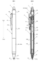
- FIG. 1 is a retractable writing instrument according to a first embodiment of the present invention, in which the pen tip is retracted into the barrel.
- FIG. 1A is a side view and FIG. 1B is a sectional view.
- FIG. 2 shows the retractable writing instrument with the pen tip protruding from the barrel.
- 2A is a side view and FIG. 2B is a sectional view.
- FIG. 3 shows a clip body that constitutes a clip of the retractable writing instrument.
- FIG. 3A is a perspective view of the clip body as viewed from above.
- FIG. 3B is a perspective view of the clip body as seen from below.
- FIG. 4 shows a state of the clip body before being assembled to the retractable writing instrument.
- 4A is a plan view
- FIG. 4B is a side view
- FIG. 4C is a bottom view
- FIG. 5 shows a clip base that constitutes a clip of the retractable writing instrument.
- 5A is a front view
- FIG. 5B is a side view
- FIG. 5C is a plan view
- FIG. 5D is a bottom view
- FIG. 5E is a rear view
- FIG. 5F is a sectional view taken along the line AA of FIG. 5B
- FIG. 5G is B of FIG. 5B.
- FIG. 6 is a sectional view taken along line B-.
- FIG. 6 shows a state of the clip body after being assembled to the retractable writing instrument.
- 6A is a side sectional view of a rear portion of the retractable writing instrument including the clip body
- FIG. 6A is a side sectional view of a rear portion of the retractable writing instrument including the clip body
- FIG. 6B is a side view of the clip body
- FIG. 6C is a sectional view of the clip body.
- FIG. 7 shows an intermediate shaft that constitutes the retractable writing instrument.
- 7A is a perspective view of a rear portion of the intermediate shaft
- FIG. 7B is a sectional view of a process of assembling the clip on the intermediate shaft.
- FIG. 8 shows a clip body that constitutes a clip of the retractable writing instrument according to the second embodiment of the present invention.
- 8A is a sectional view
- FIG. 8B is a bottom view
- FIG. 8C is a perspective view of the clip body as seen from below.
- FIG. 9 shows the unintended connection of two clip bodies without stopper walls.
- 9A is a sectional view
- FIG. 9B is a bottom view
- FIG. 9C is a perspective view of the two clip bodies as seen from below.
- FIG. 10 shows a state in which the two clip bodies having the stopper walls are prevented from being combined.
- 10A is a cross-sectional view
- FIG. 10B is a bottom view
- FIG. 10C is a perspective view of the two clip bodies as seen from below.
- FIG. 11 shows an unintended connection state of two clip bodies having no wide portion in the grip portion.
- FIG. 11A is a cross-sectional view showing a first example in an unintended combined state
- FIG. 11B is a perspective view showing another second example in the unintentional combined state.
- FIG. 11A is a cross-sectional view showing a first example in an unintended combined state
- FIG. 11B is a perspective view showing another second example in the unintentional combined state.
- FIG. 11A is a cross-sectional view showing a first example in an unintended combined state
- FIG. 12A is a cross-sectional view showing a clip body that constitutes a clip of a retractable writing instrument according to a third embodiment of the present invention.
- FIG. 12B is a cross-sectional view showing a clip body that constitutes a clip of the retractable writing instrument according to the fourth embodiment of the present invention.
- FIG. 12C is a cross-sectional view showing a clip body that constitutes a clip of a retractable writing instrument according to a fifth embodiment of the present invention.
- FIG. 13A is a cross-sectional view showing a clip body that constitutes a clip of a retractable writing instrument according to a sixth embodiment of the present invention.
- FIG. 12A is a cross-sectional view showing a clip body that constitutes a clip of a retractable writing instrument according to a sixth embodiment of the present invention.
- FIG. 13B is a cross-sectional view showing a clip body that constitutes a clip of the retractable writing instrument according to the seventh embodiment of the present invention.
- FIG. 14 shows an intermediate shaft that constitutes the retractable writing instrument of the first embodiment.
- FIG. 14A is a perspective view of a rear portion of the intermediate shaft.
- FIG. 14B is a plan view of a rear portion of the intermediate shaft.
- FIG. 15 shows the internal structure of the retractable writing instrument of the first embodiment.
- FIG. 15A is a cross-sectional view showing a protruding state of the pen tip.
- FIG. 15B is a cross-sectional view showing the pen tip in the retracted state.
- FIG. 16 shows an intermediate shaft constituting a retractable writing instrument according to the eighth embodiment of the present invention.
- FIG. 16 shows an intermediate shaft constituting a retractable writing instrument according to the eighth embodiment of the present invention.
- FIG. 16A is a perspective view of a rear portion of the intermediate shaft.
- FIG. 16B is a plan view of a rear portion of the intermediate shaft.
- FIG. 16C is a sectional view of a process of assembling the clip on the intermediate shaft.
- FIG. 17 shows the internal structure of the retractable writing instrument of the eighth embodiment.
- FIG. 17A is a cross-sectional view showing a protruding state of the pen tip.
- FIG. 17B is a cross-sectional view showing the pen tip in a retracted state.
- FIG. 18A is an enlarged view of FIG. 17A.
- FIG. 18B is an enlarged view of FIG. 17B.
- FIG. 19 shows an intermediate shaft which constitutes a retractable writing instrument according to the ninth embodiment of the present invention.
- FIG. 19 shows an intermediate shaft which constitutes a retractable writing instrument according to the ninth embodiment of the present invention.
- FIG. 19 shows an intermediate shaft which constitutes a retractable writing instrument according to the ninth embodiment of the
- FIG. 19A is a perspective view of a rear portion of the intermediate shaft.
- FIG. 19B is a plan view of a rear portion of the intermediate shaft.
- FIG. 19C is a sectional view of a process of assembling the clip on the intermediate shaft.
- FIG. 20 shows the internal structure of the retractable writing instrument of the first embodiment.
- FIG. 20A is a sectional view showing a protruding state of the pen tip.
- FIG. 20B is a cross-sectional view showing the pen tip in a retracted state.
- FIG. 21A is a plan view showing a rear side portion of the intermediate shaft which constitutes the retractable writing instrument according to the tenth embodiment of the present invention.
- FIG. 21B is a plan view showing a rear side portion of the intermediate shaft which constitutes the retractable writing instrument according to the eleventh embodiment of the present invention.
- thermochromic writing instrument that can change the handwriting of the thermochromic ink by frictional heat is used as the retractable writing instrument.
- the structure of the present invention is not limited to the thermochromic writing instrument, but can be widely applied to general retractable writing instruments.
- FIGS. 1A, 1B, 2A and 2B The configuration of the retractable writing apparatus 1 according to the first embodiment of the present invention is shown in FIGS. 1A, 1B, 2A and 2B.
- the double-headed arrow in the figure defines the "front” and “rear” of the retractable writing instrument 1.
- the retractable writing instrument 1 includes a barrel 2, a rotating member 3, a clip 4, a spring 5, a writing body 6 and a friction portion 7.
- the barrel 2 is composed of a base 21, a front shaft 22, an intermediate shaft 23, and a rear shaft 24.
- An elastic grip 22 a is attached to the outer peripheral surface of the front shaft 22.
- the friction body 7 is fitted in the mounting hole 24b (see FIG. 6A) of the rear shaft 24.
- the clip 4 is composed of a clip body 41 and a clip base 43.
- the mouthpiece 21 and the clip body 41 are made of metal, and the other components are made of synthetic resin.
- the metal mouthpiece 21 and the clip body 41 are remarkably different in texture and appearance from the synthetic resin barrel 2, which is a feature that attracts the line of sight of the user.
- the surface of the barrel 2 made of synthetic resin, for example, the surface of the intermediate shaft 23 is decorated by attaching a transfer film.
- the spring 5, the writing body 6, the rotating member 3, and the cylindrical portion 43d of the clip base 43 are sequentially housed in the barrel 2.
- the cursive body 6 includes a pen tip 61, an ink containing tube 62, a thermochromic ink 63, a follower 64, and a tail plug 65.
- the pen tip 61 is attached to the front end of the ink containing tube 62.
- the pen tip 61 of the present embodiment is a ballpoint pen tip, but the configuration of the present invention is not limited to a ballpoint pen, and can be widely applied to retractable writing instruments such as mechanical pencils and marking pens. is there.
- the thermochromic ink 63 and the follower 64 are filled inside the ink containing tube 62.
- the tail plug 65 is attached to the opening at the rear end of the ink containing tube 62.
- thermochromic ink 63 A vent hole extending in the front-rear direction is provided at the center of the tail plug 65.
- the handwriting formed on the paper surface with the thermochromic ink 63 can be thermally discolored by the friction portion 7.
- the friction part 7 generates frictional heat by being rubbed against the paper surface. Due to this frictional heat, the handwriting of the thermochromic ink 63 is thermally discolored.
- the thermochromic ink 63 is, for example, thermochromically changed from the first colored to the second colored, or from the colored to colorless.
- the pen tip 61 of the cursive body 6 is in a state of protruding from the barrel 2 or being immersed in the barrel 2 by the retracting mechanism.
- the retracting mechanism is composed of a spring 5, a rotating member 3, a clip base 43, and a slide hole 20, a cam tooth 23a, and a cam groove 23b provided in a wall of the shaft cylinder 2 (Fig. 6A).
- the spring 5 is attached to the front end of the cursive body 6 and constantly biases the cursive body 6 backward.
- the rotating member 3 and the clip base 43 are arranged behind the cursive body 6.
- the rotating member 3 is rotatably coupled to the cylindrical portion 43d of the clip base 43.
- the rotating member 3 includes four protrusions 31.
- the four ridges 31 are evenly provided on the outer surface of the rotating member 3 at intervals of 90°.
- the ridge 31 continues from the side surface of the rotating member 3 to the upper surface.
- the rear end portion of the protrusion 31 protruding from the upper surface of the rotating member 3 is an inclined surface (cam tooth) inclined in one direction.
- the clip base 43 is slidable in the front-rear direction along the slide hole 20 provided on the rear side of the barrel 2.
- the clip base 43 includes a slider 43a, a connecting portion 43c, and a cylindrical portion 43d (see FIG. 5B).
- the slider 43 a is located outside the barrel 2.
- the cylindrical portion 43d is located inside the barrel 2.
- the rear side of the clip body 41 is coupled to the slider 43a.
- the connecting portion 43c connects the slider 43a and the cylindrical portion 43d via the slide hole 20 of the shaft tube 2.
- Cam teeth 43e are provided at the front end of the cylindrical portion 43d (see FIG. 5B).
- the cam teeth 43e of the cylindrical portion 43d mesh with the rear end portion of the protrusion 31 of the rotating member 3.
- cam teeth 23a and cam grooves 23b are provided on the inner wall surface of the shaft tube 2.
- the cam teeth 23a and the cam grooves 23b alternately mesh with the protrusions 31 of the rotating member 3.
- the pen tip 61 of the writing body 6 is brought into a protruding state or a depressed state. That is, the user of the retractable writing instrument 1 slides the slider 43 a of the clip base 43 along with the clip body 41 forward along the slide hole 20 of the barrel 2. Then, in the shaft cylinder 2, the rotating member 3 is pushed by the cylindrical portion 43b of the clip base 43 and moves forward of the cam teeth 23a and the cam groove 23b.
- the rotary member 3 rotates in one direction, and the protrusion 31 meshes with either the cam tooth 23a or the cam groove 23b.
- the rotation member 3 is held while moving forward by the protrusions 31 meshing with the cam teeth 23a.
- the pen tip 61 of the writing body 6 is in a state of protruding from the front end hole 21 a of the barrel 2.
- the rotary member 3 moves rearward along the cam groove 23b.
- the pen tip 61 of the writing body 6 is in a state of being immersed in the barrel 2.
- the retractable writing instrument 1 of this embodiment is characterized by the configuration of the clip 4.
- the clip 4 of this embodiment includes a clip body 41 and a clip base 43 shown in FIG. 6A.
- a grip portion 42 is integrally provided at the front end of the clip body 41.
- the grip 42 generates an elastic force for gripping an object.
- FIGS. 3A, 3B, and 4A to 4C The configurations of the clip body 41 and the grip portion 42 of this embodiment are shown in FIGS. 3A, 3B, and 4A to 4C.
- the clip body 41 and the grip portion 42 are integrally formed by bending a single metal plate.
- the fixed end 42a shown in FIGS. 3B and 4C serves as a boundary between the clip body 41 and the grip portion 42.
- the clip body 41 forms the main appearance of the clip 4 with the fixed end 42a as a boundary.
- the grip 42 uses the fixed end 42a as a fulcrum to generate an elastic force for gripping an object.
- the clip main body 41 includes one upper wall 41a and a pair of side walls 41b.
- the upper wall 41 a extends in the front-back direction of the barrel 2.
- the pair of side walls 41b are formed by vertically bending metal plates continuous on both sides of the upper wall 41a.
- the pair of side walls 41b reaches the rear end from the front end of the upper wall 41a and further extends rearward.
- the edges of the metal plate forming the pair of side walls 41b face the transfer film attached to the surface of the barrel 2, that is, the surface of the intermediate shaft 23.
- the clip 4 of the present embodiment is configured such that an object having a thickness equal to or smaller than the clearance CL in FIG. 6A is gripped by the grip portion 42, and an object having a thickness exceeding the clearance CL is gripped by the clip body 41. ..
- the grip portion 42 is flexibly deformed to generate an elastic force, and an object having a thickness equal to or smaller than the clearance CL is gripped by the elastic force.
- the clip body 41 has a box shape surrounded by a wall of a metal plate and has high rigidity. Such a clip body 41 is slightly bent as a whole to sandwich an object having a thickness exceeding the clearance CL. Therefore, the outer shape of the clip body 41 can be designed without considering the elastic force for gripping an object. That is, the clip body 41 of the present embodiment has a high degree of freedom in designing the outer shape.
- the upper wall 41a has the narrowest width at the front end and gradually widens from the front side to the rear side. Further, as shown in FIG. 4B, the upper wall 41a curves gently from the front end to the rear end.
- the front side of the side wall 41b is designed in the shape of a gently curved ball portion. The height of the wall at the center of the side wall 41b is lower than that of the other portions, and gives the impression that the center of the clip body 41 flexes flexibly.
- the rear side of the side wall 41b is designed as a substantially parallelogram formed of straight lines, symmetrically with the front side formed of a curve.
- a pair of engaging portions 41c protruding toward the inside of the clip body 41 is formed on the rear side of the pair of side walls 41b. Further, as shown in FIG. 3B, a pair of stopper walls 41d protruding toward the back surface of the upper wall 41a are formed at the front ends of the pair of engaging portions 41c.
- a pair of engagement grooves 43b are provided on both sides of the slider 43a of the clip base 43. As shown in FIG. 6A, the pair of engaging portions 41c of the clip body 41 engages with the pair of engaging grooves 43b of the slider 43a. At this time, the pair of stopper walls 41d come into contact with the front surface of the slider 43a.
- the gripping part 42 is provided on the back side of the clip main body 41 and between the pair of side walls 41b. More specifically, the grip portion 42 is located between the front side portions of the pair of side walls 41b that are designed in the shape of a ball.
- the grip 42 is formed by bending a part of the same metal plate as the clip body 41.
- the grip 42 of this embodiment includes a beam 42b and a protrusion 42c that are continuous with each other.
- the beam 42b extends horizontally from the fixed end 42a to the rear of the barrel 2 (see FIG. 8A).
- the protrusion 42 c is bent in a V shape from the beam 42 b and protrudes toward the surface of the barrel 2.
- the top of the protrusion 42c is preferably located on a straight line passing through the highest part of the pair of side walls 41b forming the ball.
- the black dot in FIG. 4B indicates the highest portion of the pair of side walls 41b.
- the alternate long and short dash line in FIG. 4B indicates a straight line passing through the highest part of the pair of side walls 41b.
- the top of the protrusion 42c of the present embodiment is located on the alternate long and short dash line passing through the black dot in FIG. 4B.
- the rear end of the protrusion 42c is a free end 42d. Before the clip body 41 is assembled to the retractable writing instrument 1, the free end 42d of the protrusion 42c does not contact the back surface of the upper wall 41a of the clip body 41 (see FIG. 8A).
- the protrusion 42c has a width W1 that can be accommodated in the guide groove 23f of the barrel 2 shown in FIG. 7A.
- the width W1 from the front side to the rear end of the V-shaped protrusion 42c is narrower than the width W3 of the beam 42b (W1 ⁇ W3).
- the width W1 of the protrusion 42c is slightly narrower than the width W2 of the guide groove 23f of the barrel 2.
- the dimensional difference between the width W2 of the guide groove 23f and the width W1 of the protrusion 42c is preferably within the range of 0.1 mm ⁇ W2-W1 ⁇ 4.0 mm.
- the protrusion 42c is housed between the pair of side surfaces 234 of the guide groove 23f, and moves in the front-rear direction of the barrel 2 along the guide groove 23f.
- the protrusion 42c does not come into contact with any part of the shaft tube 2 other than the guide groove 23f.
- the width W1 of the protrusion 42c is preferably wider than 20% of the width W3 of the beam 42b in order to obtain sufficient strength (W3 ⁇ 0.2 ⁇ W1).
- the grip portion 42 of the present embodiment is configured to generate a two-step elastic force according to the thickness of the object to be gripped.
- the elastic force in the first stage is generated by the deformation of the beam 42b with the fixed end 42a shown in FIG. 6C as the fulcrum.
- FIG. 6A when the clip body 41 is assembled to the retractable writing instrument 1, the beam 42b deforms toward the back surface of the upper wall 41a of the clip body 41 with the fixed end 42a as a fulcrum.
- the protrusion 42c exerts a first-stage elastic force on the guide groove 23f of the shaft cylinder 2 (see the protrusion amounts AM1 and AM2 shown in FIGS. 4B and 6B).
- the protrusion 42c constantly applies a load of 200 gf to the guide groove 23f of the barrel 2.
- the elastic force in the second stage is generated when the protrusion 42c shown in FIG. 6C is deformed with its top as a fulcrum. That is, when the beam 42b is further deformed with the fixed end 42a as a fulcrum in the state where the elastic force of the first stage is generated, the free end 42d of the protrusion 42c contacts the back surface of the upper wall 41a of the clip body 41. As a result, the protrusion 42c is deformed with its top as a fulcrum to generate a second-stage elastic force.
- the grip portion 42 of the present embodiment grips a thin object by the elastic force of the first step (for example, 200 gf), and a thick object by the elastic force (for example, over 200 gf) that is the sum of the first step and the second step. Hold it.
- the clip base 43 includes the slider 43a, the connecting portion 43c, and the cylindrical portion 43d.
- the slider 43a is provided with a pair of engagement grooves 43b.
- the pair of engaging grooves 43b engage with the pair of engaging portions 41c of the clip body 41.
- Cam teeth 43e are provided at the front end of the cylindrical portion 43d. The cam teeth 43e mesh with the rear end portion of the protrusion 31 of the rotating member 3.
- the clip base 43 of the present embodiment supports the clip body 41 coupled to the slider 43a at a predetermined height so that the surface of the barrel 2 is not damaged.
- the clip base 43 supports the clip body 41 at a height such that the pair of side walls 41b do not contact the surface of the barrel 2 and the grip 42 contacts the bottom surface 233 of the guide groove 23f.
- the clearance CL shown in FIG. 6A is maintained between the pair of side walls 41b and the surface of the barrel 2.
- the clearance CL is maintained by the height at which the clip base 43 supports the clip body 41.
- the clearance CL is maintained by the elastic force (for example, 200 gf) of the grip portion 42 generated when the clip body 41 is assembled to the retractable writing instrument 1.
- the guide groove 23f described above is provided on the rear side of the intermediate shaft 23 that constitutes the shaft cylinder 2.
- the guide groove 23f is a groove extending in the front-rear direction of the barrel 2 and is composed of a bottom surface 233 and a pair of side surfaces 234. As shown in FIG. 6A, the bottom surface 233 of the guide groove 23f comes into contact with the protruding portion 42c forming the grip portion 42 of the clip 4.
- the pair of side surfaces 234 of the guide groove 23f limits the lateral movement of the protrusion 42c.
- the guide groove 23f having such a structure guides the clip 4, which is slid for retracting the pen tip 61, in the front-rear direction of the barrel 2 and moves it in a straight line.
- the surface of the intermediate shaft 23 is decorated by attaching the transfer film, but the transfer film is not attached to the guide groove 23f.
- the guide groove 23f of the present embodiment has a total length exceeding the length required for sliding the clip 4.
- the guide groove 23f includes a first region 231 on the front side and a second region 232 on the rear side.
- the second region 232 communicates with the front end of the first elongated hole 23e provided on the rear side of the intermediate shaft 23.
- the first elongated hole 23e constitutes the slide hole 20 together with the second elongated hole 24a of the rear shaft 24 shown in FIG. 2B.
- the first area 231 of the guide groove 23f is used for sliding the clip 4 for retracting the pen tip 61. That is, when the pen tip 61 is projected and retracted, the clip 4 is moved in the front-back direction within the range of the length of the first region 231.
- the second region 232 of the guide groove 23f is used when the clip 4 is assembled to the intermediate shaft 23.
- the clip 4 is assembled by inserting the cylindrical portion 43d of the clip base 43 into the inside of the intermediate shaft 23.
- the protrusion 42c forming the grip 42 of the clip 4 passes through the first elongated hole 23e and moves from the second region 232 of the guide groove 23f to the first region 231. Be guided.
- the clip 4 can be assembled to the intermediate shaft 23 without the metal protrusion 42c coming into contact with the surface of the intermediate shaft 23.
- the clip 4 of the present embodiment can be made of a metal plate and can be adjusted to an appropriate elastic force that does not damage thin paper or cloth. That is, the metal clip 4 is composed of the clip body 41 and the grip portion 42.
- the outer appearance of the clip 4 is formed by the outer shape of a box-shaped clip body 41 surrounded by a plurality of walls.
- the elastic force of the clip 4 is generated by the grip portion 42 provided on the back side of the clip body 41.
- the configuration of the grip portion 42 does not affect the appearance of the clip 4. Therefore, the grip portion 42 can be freely configured to generate an appropriate elastic force.
- the outer shape of the clip body 41 can be designed with little consideration given to the elastic force for gripping an object, and the degree of freedom in design is high.
- the clip 4 of this embodiment does not damage the surface of the barrel 2 by the edge of the metal plate.
- the clearance CL shown in FIG. 6A is maintained between the metal clip body 41 and the surface of the barrel 2 to which the transfer film is attached. This prevents the pair of side walls 41b of the clip body 41 from contacting the surface of the barrel 2.
- the metal grip portion 42 contacts only the guide groove 23f to which the transfer film is not attached, and does not contact the surface of the barrel 2 to which the transfer film is attached. With the above configuration, the metal clip 4 does not contact and damage the surface of the barrel 2.
- the clip 4 of the present embodiment can prevent contact between the metal clip 4 and the surface of the barrel 2 without providing a protrusion on the surface of the barrel 2 as in the conventional case. Therefore, the transfer film can be efficiently attached to the surface of the barrel 2.
- the grip portion 42 always exerts an elastic force on the guide groove 23f of the shaft tube 2.
- the elastic force of the grip portion 42 always suppresses the rattling of the clip 4.
- the operability of the clip 4 is improved. That is, the rattling-free clip 4 can be slid straight along the slide hole 20 and the guide groove 23f.
- generation of unpleasant sound or vibration due to rattling of the clip 4 is prevented.
- rattling of the clip 4 during writing by the retractable writing instrument 1 is suppressed, and the usability of the retractable writing instrument 1 is improved.
- the pair of stopper walls 41d provided on one clip body 41 prevent unintended coupling of the two clip bodies 41.
- the automatic assembly of the retractable writing instrument 1 can be smoothly performed.
- the prevention of unintended coupling of the two clip bodies 41 will be described in detail in the second embodiment below.
- the pair of stopper walls 41d shown in FIGS. 8A to 8C and one wide portion 42e Unintentional coupling of the two clip bodies 41 is prevented by the pair of stopper walls 41d shown in FIGS. 8A to 8C and one wide portion 42e.
- the configuration of the pair of stopper walls 41d has already been described in the first embodiment.
- the pair of stopper walls 41d are formed at the front ends of the pair of engaging portions 41c and project toward the back surface of the upper wall 41a.
- the wide portion 42e is provided at the rear end portion including the free end 42d of the grip portion 42.
- the width W4 of the wide portion 42e is at least wider than the width W1 of the protruding portion 42c, and preferably has a width that is 1 ⁇ 2 or more of the distance between the pair of side walls 41b of the clip body 41.
- the width W4 of the wide portion 42e of the present embodiment has substantially the same size as the width W3 of the beam 42, but may exceed the width W3 of the beam 42 (
- FIGS. 9A to 9C show two clip bodies 41 without the stopper wall 41d and the wide portion 42e.
- the configuration of the clip body 41 is the same as the clip body 41 of the first embodiment shown in FIGS. 4A to 4C, except that the stopper wall 41d is not provided.
- the clip body 41 has an outer shape in which the width of the front end is the smallest and the width gradually increases from the front side to the rear side. Further, as shown in FIGS. 9A and 9C, the rear end opening of the clip body 41 is surrounded by the upper wall 41a, the pair of side walls 41b, and the pair of engaging portions 41c. Therefore, the narrow front side of one clip body 41 may be deeply fitted to the wide rear side of the other clip body 41. The automatic assembly machine cannot separate the two fitted clip bodies 41. Therefore, the automatic assembly of the retractable writing instrument 1 is temporarily stopped.
- 10A to 10C show two clip bodies 41 provided with a pair of stopper walls 41d.
- the pair of stopper walls 41d provided on one clip body 41 abut on the front ends of the other clip bodies 41 and prevent the one and the other clip bodies 41 from fitting.
- the plurality of clip bodies 41 are separately supplied to the automatic assembly machine, and the automatic assembly of the retractable writing instrument 1 is smoothly performed.
- the grip portions 42 of the two clip bodies 41 not provided with the wide portion 42e may be entangled with each other.
- the automatic assembly machine cannot separate the two clip bodies 41 in which the grips 42 are intertwined. Therefore, the automatic assembly of the retractable writing instrument 1 is temporarily stopped.
- the wide portion 42e shown in FIGS. 8A to 8C the entanglement between the grip portions 42 of the two clip bodies 41 is reduced. That is, the wide portion 42e has a width that is 1 ⁇ 2 or more of the distance between the pair of side walls 41b of the clip body 41. Therefore, the wide portion 42e of the one clip body 41 is unlikely to enter the gap between the grip portions 42 of the other clip bodies 41. As a result, the entanglement between the grips 42 is reduced. According to such a wide portion 42e, the plurality of clip bodies 41 are separately supplied to the automatic assembly machine, and the automatic assembly of the retractable writing instrument 1 is smoothly performed.
- the protruding portion 42c when the free end 42d contacts the back surface of the upper wall 41a of the clip body 41, the protruding portion 42c is deformed with its top as a fulcrum, and a second-stage elastic force is generated.
- the wide portion 42e suppresses rattling of the protrusion 42c and stabilizes the deformation of the protrusion 42c when the elastic force of the second stage is generated.
- the above-described technical effect of the wide portion 42e becomes more remarkable as the width W4 of the wide portion 42e becomes wider. That is, the wider the width W4 of the wide portion 42e, the more reliably the entanglement between the gripping portions 42 of the two clip bodies 41 is prevented. Further, the wider the width W4 of the wide portion 42e, the less rattling of the protruding portion 42c, and the more stable the deformation of the protruding portion 42c when the elastic force of the second stage is generated.
- the configuration of the gripping part 42 of the clip body 41 is not limited to the V-shape shown in FIGS. 4A to 4C.
- the grip 42 may have the configuration shown in FIGS. 12A to 12C, for example.
- FIG. 12A shows a clip body 41 and a grip portion 42 that constitute a clip of a retractable writing instrument according to a third embodiment of the present invention.
- the clip body 41 and the grip portion 42 are integrally provided by a single metal plate.
- An arcuate protrusion 42f is formed on the grip 42.
- the arc-shaped protrusion 42f protrudes from the beam 42b toward the surface of the barrel 2.
- the radius of curvature R of the top of the protrusion 42f is preferably larger than 0.5 mm, more preferably larger than 1.5 mm.
- the rear end of the protrusion 42f is a free end 42d.
- Such an arc-shaped protrusion 42f functions similarly to the V-shaped protrusion 42c shown in FIGS. 4A to 4C.
- the wide portion 42e shown in FIGS. 8A to 8C may be provided at the rear end portion including the free end 42d of the grip portion 42 of the present embodiment.
- FIG. 12B shows a clip body 41 and a grip portion 42 that constitute a clip of a retractable writing instrument according to a fourth embodiment of the present invention.
- the clip body 41 and the grip portion 42 are integrally provided by a single metal plate.
- the grip 42 is formed with a W-shaped protrusion 42g.
- the W-shaped protrusion 42g protrudes from the beam 42b toward the surface of the barrel 2.
- the W-shaped protrusion 42g has two tops. The boundary between the two peaks of the protrusion 42g is the lowest valley. It is preferable that the valleys of the protrusions 42g be located on a straight line passing through the highest part of the pair of side walls 41b forming the ball.
- FIG. 12B indicates the highest portion of the pair of side walls 41b.
- the alternate long and short dash line in FIG. 12B indicates a straight line passing through the highest part of the pair of side walls 41b.
- the valley portion of the protrusion 42g of the present embodiment is located on the alternate long and short dash line passing through the black dot in FIG. 12B.
- the rear end of the protrusion 42g is a free end 42d.
- Such a W-shaped protrusion 42g functions similarly to the V-shaped protrusion 42c shown in FIGS. 4A to 4C.
- the wide portion 42e shown in FIGS. 8A to 8C may be provided at the rear end portion including the free end 42d of the grip portion 42 of the present embodiment.
- FIG. 12C shows a clip body 41 and a grip portion 42 that constitute a clip of a retractable writing instrument according to a fifth embodiment of the present invention.
- the clip body 41 and the grip portion 42 are integrally provided by a single metal plate.
- An inverted trapezoidal protrusion 42h is formed on the grip 42.
- the inverted trapezoidal protrusion 42h protrudes from the beam 42b toward the surface of the barrel 2.
- the rear end of the protrusion 42h is a free end 42d.
- Such an inverted trapezoidal protrusion 42h functions similarly to the V-shaped protrusion 42c shown in FIGS. 4A to 4C.
- the wide portion 42e shown in FIGS. 8A to 8C may be provided at the rear end portion including the free end 42d of the grip portion 42 of the present embodiment.
- the clip main body 41 and the gripping part 42 are not limited to the configuration integrally provided by a single metal plate.
- the clip body 41 and the grip 42 may have the configuration shown in FIGS. 13A and 13B, for example.
- FIG. 13A shows a clip main body 41 and a grip portion 44 that constitute a clip of a retractable writing instrument according to a sixth embodiment of the present invention.
- the clip body 41 is configured by bending a single metal plate.
- the grip portion 44 is integrally formed of synthetic resin.
- the synthetic resin gripping portion 44 has a fixed point 44a, a beam 44b, a protrusion 44c, and a free end 44d similar to the gripping portion 42 shown in FIGS. 4A to 4C.
- the synthetic resin grip portion 44 is fixed to the back surface of the upper wall 41a of the metal clip body 41.
- the grip portion 44 is fixed to the back surface of the upper wall 41a, for example, by adhesion or fitting.
- Such a synthetic resin gripping portion 44 functions similarly to the metal gripping portion 42 shown in FIGS. 4A to 4C.
- FIG. 13B shows a clip body 45 and a grip portion 42 that constitute a clip of a retractable writing instrument according to a seventh embodiment of the present invention.
- the clip body 45 is integrally molded of synthetic resin.
- the grip portion 42 is configured by bending a single metal plate.
- the clip body 45 made of synthetic resin has an upper wall 45a, a pair of side walls 45b, and a pair of engaging portions 45c similar to the clip body 41 shown in FIGS. 4A to 4C.
- the metal grip 42 is fixed to the back surface of the upper wall 45a of the clip body 45 made of synthetic resin.
- the grip portion 42 is fixed to the back surface of the upper wall 45a by, for example, bonding or fitting. Such a metal gripping portion 42 functions similarly to the metal gripping portion 42 shown in FIGS. 4A to 4C.
- the guide groove 23f provided on the intermediate shaft 23 is not limited to the configuration shown in FIGS. 7A and 7B of the first embodiment described above.
- the guide groove 23f of the first embodiment includes first and second regions 231 and 232.
- the first area 231 is used for sliding the clip 4 for retracting the pen tip 61 (see FIGS. 1B and 2B). That is, when the pen tip 61 is projected and retracted, the clip 4 is moved in the front-back direction within the range of the length of the first region 231.
- FIGS. 15A and 15B show the internal configuration of the retractable writing instrument 1 according to the first embodiment.
- FIG. 15A shows a state in which the pen tip 61 projects from the barrel 2.
- FIG. 15B shows a state in which the pen tip 61 is immersed in the barrel 2.
- the grip portion 42 of the clip 4 is located in the front half portion 231a of the first area 231.
- FIG. 15B when the pen tip 61 is in the state of being retracted into the barrel 2, the grip portion 42 of the clip 4 is located in the second half portion 231b of the first area 231.
- the guide groove 23f of the first embodiment has a bottom surface 233 in the latter half portion 231b of the first region 231. For this reason, the movement of the clip 4 to the rear rarely stops immediately before the pen tip 61 enters the completely immersed state shown in FIG. 15B. That is, the retractable writing instrument 1 according to the first embodiment has a technical problem that the normal operation of the clip 4 for putting the pen tip 61 into the retracted state is not reliably performed.
- FIGS. 15A and 15B causes of such technical problems will be described with reference to FIGS. 15A and 15B.
- the clip 4 is slid to the rear of the barrel 2 by the biasing force P1 of the spring 5 (see FIGS. 1B and 2B) attached to the front end of the writing body 6.
- the grip portion 42 of the clip 4 causes the elastic force P2 to the bottom surface 233 of the guide groove 23f.
- the clip 4 receives a reaction force (see the gray arrow in FIGS. 15A and 15B) opposite to the elastic force P2 from the bottom surface 233.
- the clip 4 is tilted with the clip base 43 as a fulcrum by the reaction force in the direction opposite to the elastic force P2.
- the clip base 43 in the tilted state is pressed against the surface and the inner surface of the intermediate shaft 23 and the rear shaft 24 to generate frictional resistance (see a portion surrounded by a chain line in FIGS. 15A and 15B).
- the frictional resistance of the clip base 43 has a preferable effect of suppressing rattling of the clip 4.
- the frictional resistance of the clip base 43 causes a problem of stopping the rearward movement of the clip 4 immediately before the pen tip 61 is in the fully retracted state shown in FIG. 15B.
- the elastic force P2 of the grip 42 is not the only cause of stopping the rearward movement of the clip 4.
- the change in the biasing force P1 depending on the expansion and contraction of the spring 5 also causes the movement of the clip 4 to the rear to be stopped. That is, the urging force P1 of the spring 5 increases as the spring 5 is compressed and decreases as the spring 5 extends. Therefore, the urging force P1 of the spring 5 is maximum in the protruding state of the pen tip 61 shown in FIG. 15A, and is minimum in the retracted state of the pen tip 61 shown in FIG. 15B.
- FIGS. 16 to 18 a retractable writing instrument according to an eighth embodiment of the present invention will be described with reference to FIGS. 16 to 18.
- the retractable writing instrument according to the eighth embodiment is provided with a configuration for solving the problem that the backward movement of the clip 4 is stopped.
- FIGS. 16A, 16B and 16C show the intermediate shaft 23 of the retractable writing instrument according to the eighth embodiment.
- the retractable writing instrument according to the eighth embodiment is characterized by the configuration of the guide groove 23f provided on the intermediate shaft 23.
- the guide groove 23f includes a bottom surface 233, a pair of side surfaces 234, and a through groove 235.
- the bottom surface 233 of the guide groove 23f is not an essential component, but is formed in a portion of the guide groove 23f other than the latter half portion 231b of the first region 231.
- the bottom surface 233 is formed on the front half portion 231a of the first region 231.
- the bottom surface 233 has substantially the same length as the front half portion 231a.
- the bottom surface 233 of this embodiment has a length slightly shorter than the entire length of the front half portion 231a of the first region 231. That is, as shown in FIG. 17A, the bottom surface 233 has a minimum length that allows the bottom surface 233 to come into contact with the protruding portion 42c forming the grip portion 42 of the clip 4 when the pen tip 61 is in the protruding state. There is.
- the through groove 235 of the guide groove 23f is formed at least in the second half portion 231b of the first region 231.
- the through groove 235 of the present embodiment is formed over the entire first region 231 to the second region 232 except the bottom surface 233, and is continuous with the first elongated hole 23e.
- the projecting portion 42c forming the gripping portion 42 of the clip 4 is the front half portion of the first region 231 of the guide groove 23f. Located at 231a.
- the grip portion 42 of the clip 4 causes the elastic force P2 to the bottom surface 233 of the guide groove 23f.
- the clip 4 receives a reaction force (see the gray arrow in FIG. 17A) opposite to the elastic force P2 from the bottom surface 233.
- the clip 4 is tilted with the clip base 43 as a fulcrum by the reaction force in the direction opposite to the elastic force P2.
- the clip base 43 in the inclined state is pressed against the surface and the inner surface of the intermediate shaft 23 and the rear shaft 24 to generate frictional resistance (see a portion surrounded by a chain line in FIG. 17A).
- the frictional resistance of the clip base 43 has a preferable effect of suppressing rattling of the clip 4. That is, the bottom surface 233 formed in the front half portion 231a of the first area 231 of the guide groove 23f prevents the clip 4 from rattling when the pen tip 61 is in the protruding state.
- the protruding state of the pen tip 61 shown in FIG. 17A shifts to the retracted state of the pen tip 61 shown in FIG. 17B by sliding the clip 4 in front of the barrel 2 (see FIG. 2A). ..
- the clip 4 is moved by the urging force P1 of the spring 5 (see FIGS. 1B and 2B) attached to the front end portion of the writing body 6 of the barrel 2. It is slid backward.
- the protruding portion 42c forming the grip portion 42 of the clip 4 passes through the boundary between the front half portion 231a and the rear half portion 231b in the first region 231 of the guide groove 23f. At a position to be inserted into the through groove 235 from above the bottom surface 233. After that, the grip portion 42 of the clip 4 moves along the through groove 235 to the boundary between the second half 231b of the first region 231 and the second region 232. This brings the pen tip 61 into the completely immersed state shown in FIG. 17B.
- the grip portion 42 of the clip 4 causes the elastic force P2 until the pen tip 61 moves from the protruding state to the retracted state. Disappear.
- the reaction force in the opposite direction to the elastic force P2 becomes zero, and the frictional resistance of the clip base 43 also becomes zero. Therefore, according to the guide groove 23f of the present embodiment, the rearward movement of the clip 4 is not stopped immediately before the pen tip 61 is in the completely retracted state shown in FIG. 17B. That is, in the retractable writing instrument according to the present embodiment, the normal operation of the clip 4 for putting the pen tip 61 into the retracted state is reliably performed.
- the through groove 235 formed in the second region 232 of the guide groove 23f is used when the clip 4 is assembled to the intermediate shaft 23.
- the protruding portion 42c forming the grip portion 42 of the clip 4 passes through the first elongated hole 23e and the through groove formed in the second region 232 of the guide groove 23f. It is guided to the first region 231 by 235.
- the clip 4 can be assembled to the intermediate shaft 23 without the metal protrusion 42c coming into contact with the surface of the intermediate shaft 23.
- an inclined surface 233a that descends toward the through groove 235 is formed at the rear end of the bottom surface 233 of the guide groove 23f.
- an inclined surface 233a it becomes possible for the protruding portion 42c forming the grip portion 42 of the clip 4 to smoothly move up and down on the bottom surface 233.
- the sliding operation of the clip 4 for retracting the pen tip 61 becomes smooth.
- a gap D is formed between the rear end of the bottom surface 233 of the guide groove 23f and the protruding portion 42c of the clip 4 when the pen tip 61 is retracted. .. Due to the distance D, the protruding portion 42c of the clip 4 enters the through groove 235 and the elastic force P2 of the grip portion 42 becomes zero before the pen tip 61 is in the completely retracted state shown in FIG. 17B.
- the surface of the grip portion 42 does not come into contact with the rear end of the bottom surface 233, and in the process of transition from the protruding state of the pen tip 61 to the retracted state, the surface of the grip portion 42 and the rear end of the bottom surface 233. There is no frictional resistance between them. Due to the technical effect of the distance D, the rearward movement of the clip 4 is more reliably prevented.
- the guide groove 23f of the retractable writing instrument according to the ninth embodiment has a first bottom surface 233A, a through groove 235, and a second bottom surface 233B.
- the first bottom surface 233A is formed in the front half portion 231a of the first region 231 as in the above-described eighth embodiment.
- the second bottom surface 233B is formed in the second region 232.
- the through groove 235 is formed between the first bottom surface 233A and the second bottom surface 233B.
- the through hole 235 of the present embodiment has a length that extends from the rear end of the first bottom surface 233A to the front end of the second bottom surface 233B beyond the boundary between the first region 231 and the second region 232.
- the guide groove 23f of this embodiment also has the same technical effect as that of the above-described eighth embodiment.
- the protrusion 42c of the clip 4 comes into contact with the first bottom surface 233A of the guide groove 23f, so that the grip portion 42 of the clip 4 moves to the guide groove 23f.
- An elastic force P2 is generated on the first bottom surface 233A.
- the clip 4 is tilted with the clip base 43 as a fulcrum by a reaction force (see a gray arrow in FIG. 20A) opposite to the elastic force P2.
- the clip base 43 in the inclined state is pressed against the surface and the inner surface of the intermediate shaft 23 and the rear shaft 24 to generate frictional resistance (see a portion surrounded by a chain line in FIG. 20A).
- the frictional resistance of the clip base 43 has a preferable effect of suppressing rattling of the clip 4.
- the projecting portion 42c of the clip 4 passes through the boundary between the front half portion 231a and the rear half portion 231b in the first region 231 of the guide groove 23f, and is located at the first position. It enters into the through groove 235 from above the bottom surface 233A. After that, the grip portion 42 of the clip 4 moves along the through groove 235 to the boundary between the second half 231b of the first region 231 and the second region 232. This brings the pen tip 61 into the completely immersed state shown in FIG. 20B.
- the grip portion 42 of the clip 4 causes the elastic force P2 until the pen tip 61 moves from the protruding state to the retracted state. Disappear.
- the reaction force in the opposite direction to the elastic force P2 becomes zero, and the frictional resistance of the clip base 43 also becomes zero. Therefore, according to the guide groove 23f of the present embodiment, the rearward movement of the clip 4 is not stopped immediately before the pen tip 61 is in the completely retracted state shown in FIG. 20B. That is, in the retractable writing instrument according to the present embodiment, the normal operation of the clip 4 for putting the pen tip 61 into the retracted state is reliably performed.
- the second region 232 of the guide groove 23f is used when the clip 4 is assembled to the intermediate shaft 23.
- the protruding portion 42c forming the grip portion 42 of the clip 4 passes through the first elongated hole 23e and is moved to the first region 231 by the second region 232 of the guide groove 23f. Be guided.
- the clip 4 can be assembled to the intermediate shaft 23 without the metal protrusion 42c coming into contact with the surface of the intermediate shaft 23.
- the rigidity of the rear portion of the intermediate shaft 23 is improved. That is, the through groove 235 and the first elongated hole 23e are formed in the rear portion of the intermediate shaft 23. As shown in FIG. 16B, when the through groove 235 and the first elongated hole 23e are continuous, the rigidity of the rear side portion of the intermediate shaft 23 is reduced and the intermediate shaft 23 is easily bent.
- the second bottom surface 233B shown in FIG. 19B interrupts the continuity of the through groove 235 and the first elongated hole 23e, and improves the rigidity of the rear portion of the intermediate shaft 23. As a result, the rear portion of the intermediate shaft 23 is less likely to bend, and the transfer film can be efficiently attached to the surface of the intermediate shaft 23.
- FIG. 21A shows the intermediate shaft 23 of the retractable writing instrument according to the tenth embodiment.
- the guide groove 23f of the retractable writing instrument according to the tenth embodiment does not have the bottom surface 233 and is composed of the through groove 235 and the pair of side surfaces 234.
- the through groove 235 of the present embodiment is formed over the entire first region 231 to the second region 232 and is continuous with the first elongated hole 23e.
- the grip portion 42 of the clip 4 does not always generate the elastic force P2 regardless of the state of the pen tip 61.
- the reaction force in the opposite direction to the elastic force P2 becomes zero, and the frictional resistance of the clip base 43 also becomes zero. Therefore, the backward movement of the clip 4 is not stopped. That is, in the retractable writing instrument according to the present embodiment, the normal operation of the clip 4 for putting the pen tip 61 into the retracted state is reliably performed.
- the through groove 235 formed in the second region 232 of the guide groove 23f is used when the clip 4 is assembled to the intermediate shaft 23.
- the protruding portion 42c forming the grip portion 42 of the clip 4 passes through the first elongated hole 23e and the through groove formed in the second region 232 of the guide groove 23f. It is guided to the first region 231 by 235.
- the clip 4 can be assembled to the intermediate shaft 23 without the metal protrusion 42c coming into contact with the surface of the intermediate shaft 23.
- FIG. 21B shows the intermediate shaft 23 of the retractable writing instrument according to the eleventh embodiment.
- the guide groove 23f of the retractable writing instrument according to the eleventh embodiment has only the first region 231 and does not have the second region 232.
- a bottom surface 233 is formed on the first half portion 231a of the first region 231.
- a through groove 235 is formed in the second half 231b of the first region 231.
- the guide groove 23f of this embodiment also has the same technical effect as that of the above-described eighth embodiment.
- the protruding portion 42c of the clip 4 contacts the bottom surface 233 of the guide groove 23f, so that the grip portion 42 of the clip 4 has an elastic force with respect to the bottom surface 233 of the guide groove 23f.
- P2 see FIG. 17A.
- the clip 4 is tilted with the clip base 43 as a fulcrum by the reaction force in the direction opposite to the elastic force P2.
- the clip base 43 in the inclined state is pressed against the surface and the inner surface of the intermediate shaft 23 and the rear shaft 24 to generate frictional resistance.
- the frictional resistance of the clip base 43 has a preferable effect of suppressing rattling of the clip 4.
- the protruding portion 42c of the clip 4 passes through the boundary between the front half portion 231a and the rear half portion 231b in the first region 231 of the guide groove 23f, and the bottom surface 233. From above into the through groove 235. After that, the grip portion 42 of the clip 4 moves to the rear of the latter half portion 231b of the first region 231 along the through groove 235. As a result, the pen tip 61 is completely immersed.
- the grip portion 42 of the clip 4 causes the elastic force P2 until the pen tip 61 moves from the protruding state to the retracted state. Disappear.
- the reaction force in the opposite direction to the elastic force P2 becomes zero, and the frictional resistance of the clip base 43 also becomes zero. Therefore, according to the guide groove 23f of the present embodiment, the backward movement of the clip 4 is not stopped immediately before the pen tip 61 is completely retracted. That is, in the retractable writing instrument according to the present embodiment, the normal operation of the clip 4 for putting the pen tip 61 into the retracted state is reliably performed.
- the guide groove 23f does not have the second region 232, the continuity of the through groove 235 of the first region 231 and the first elongated hole 23e is broken. This improves the rigidity of the rear portion of the intermediate shaft 23. As a result, the rear portion of the intermediate shaft 23 is less likely to bend, and the transfer film can be efficiently attached to the surface of the intermediate shaft 23.
Landscapes
- Clips For Writing Implements (AREA)
- Mechanical Pencils And Projecting And Retracting Systems Therefor, And Multi-System Writing Instruments (AREA)
- Fittings On The Vehicle Exterior For Carrying Loads, And Devices For Holding Or Mounting Articles (AREA)
Priority Applications (6)
| Application Number | Priority Date | Filing Date | Title |
|---|---|---|---|
| CN202080008833.6A CN113316521B (zh) | 2019-01-18 | 2020-01-09 | 伸缩式书写工具 |
| EP20741630.6A EP3912827A4 (en) | 2019-01-18 | 2020-01-09 | RETRACTABLE WRITING INSTRUMENT |
| US17/423,544 US11912058B2 (en) | 2019-01-18 | 2020-01-09 | Retractable writing instrument |
| JP2020566387A JP7333343B2 (ja) | 2019-01-18 | 2020-01-09 | 出没式筆記具 |
| KR1020217019649A KR20210114397A (ko) | 2019-01-18 | 2020-01-09 | 출몰식 필기구 |
| JP2023131832A JP2023154429A (ja) | 2019-01-18 | 2023-08-14 | 筆記具のクリップ |
Applications Claiming Priority (4)
| Application Number | Priority Date | Filing Date | Title |
|---|---|---|---|
| JP2019-007086 | 2019-01-18 | ||
| JP2019007086 | 2019-01-18 | ||
| JP2019-101625 | 2019-05-30 | ||
| JP2019101625 | 2019-05-30 |
Publications (1)
| Publication Number | Publication Date |
|---|---|
| WO2020149201A1 true WO2020149201A1 (ja) | 2020-07-23 |
Family
ID=71613855
Family Applications (1)
| Application Number | Title | Priority Date | Filing Date |
|---|---|---|---|
| PCT/JP2020/000396 WO2020149201A1 (ja) | 2019-01-18 | 2020-01-09 | 出没式筆記具 |
Country Status (7)
| Country | Link |
|---|---|
| US (1) | US11912058B2 (zh) |
| EP (1) | EP3912827A4 (zh) |
| JP (2) | JP7333343B2 (zh) |
| KR (1) | KR20210114397A (zh) |
| CN (1) | CN113316521B (zh) |
| TW (1) | TWI809239B (zh) |
| WO (1) | WO2020149201A1 (zh) |
Cited By (1)
| Publication number | Priority date | Publication date | Assignee | Title |
|---|---|---|---|---|
| WO2023202528A1 (zh) * | 2022-04-22 | 2023-10-26 | 青岛点石文具用品有限公司 | 按压式书写笔 |
Citations (6)
| Publication number | Priority date | Publication date | Assignee | Title |
|---|---|---|---|---|
| JPS57179986U (zh) * | 1981-05-13 | 1982-11-15 | ||
| US6773185B1 (en) * | 2003-07-01 | 2004-08-10 | Ming-Jen Hsieh | Retractile pen |
| WO2011096357A1 (ja) | 2010-02-03 | 2011-08-11 | パイロットインキ株式会社 | 筆記具 |
| JP2012006315A (ja) * | 2010-02-03 | 2012-01-12 | Pilot Ink Co Ltd | 熱変色性筆記具 |
| JP2016097682A (ja) * | 2014-11-18 | 2016-05-30 | ジュ チョン,クァン | 出没式筆記具のプッシュロック装置{pushlocksystemforslidetypewritingtools} |
| JP2017024224A (ja) | 2015-07-17 | 2017-02-02 | 三菱鉛筆株式会社 | 筆記具 |
Family Cites Families (16)
| Publication number | Priority date | Publication date | Assignee | Title |
|---|---|---|---|---|
| US1462591A (en) * | 1922-04-17 | 1923-07-24 | Andersen Gammel | Clip |
| US5336006A (en) * | 1992-10-09 | 1994-08-09 | Bic Corporation | Retractable writing instrument having replaceable cartridge |
| JP2002127677A (ja) * | 2000-10-23 | 2002-05-08 | Kotobuki:Kk | クリップ取付構造 |
| JP2003170699A (ja) * | 2001-12-07 | 2003-06-17 | Kotobuki:Kk | クリップ取付構造 |
| TW532298U (en) * | 2002-02-04 | 2003-05-11 | Jin-Shing Ye | Improved retaining structure for pen clip |
| DE20213245U1 (de) * | 2002-08-29 | 2004-01-08 | Gottlieb Roll Gmbh & Co. Kg | Halteclip für Schreibgeräte |
| FR2908677B1 (fr) | 2006-11-17 | 2009-02-20 | Air Liquide | Procede de soudage par faisceau laser a penetration amelioree |
| KR20090006428U (ko) * | 2007-12-24 | 2009-06-29 | 가부시키가이샤 고도부키 | 노크식 필기구 |
| FR2935637B1 (fr) * | 2008-09-10 | 2010-09-24 | Bic Soc | Structure de montage d'une agrafe pour un instrument d'ecriture |
| JP5698927B2 (ja) | 2010-06-25 | 2015-04-08 | パイロットインキ株式会社 | 筆記具 |
| FR2988029A1 (fr) * | 2012-03-16 | 2013-09-20 | Bic Soc | Structure de montage d'une agrafe pour un instrument d'ecriture |
| KR102256654B1 (ko) * | 2013-12-19 | 2021-05-25 | 제브라 가부시키가이샤 | 복수 출몰식 필기구 |
| JP5735617B1 (ja) | 2013-12-19 | 2015-06-17 | ゼブラ株式会社 | 複数出没式筆記具 |
| JP2016107518A (ja) | 2014-12-05 | 2016-06-20 | 株式会社サクラクレパス | 出没式筆記具 |
| EP3392056A4 (en) * | 2015-12-18 | 2019-11-06 | Kabushiki Kaisha Pilot Corporation (also trading as Pilot Corporation) | CLIQUET TYPE WRITING INSTRUMENT |
| CN207241238U (zh) * | 2017-05-25 | 2018-04-17 | 无锡宏恩科技有限公司 | 一种笔夹 |
-
2020
- 2020-01-09 WO PCT/JP2020/000396 patent/WO2020149201A1/ja unknown
- 2020-01-09 TW TW109100749A patent/TWI809239B/zh active
- 2020-01-09 KR KR1020217019649A patent/KR20210114397A/ko active Search and Examination
- 2020-01-09 JP JP2020566387A patent/JP7333343B2/ja active Active
- 2020-01-09 US US17/423,544 patent/US11912058B2/en active Active
- 2020-01-09 EP EP20741630.6A patent/EP3912827A4/en active Pending
- 2020-01-09 CN CN202080008833.6A patent/CN113316521B/zh active Active
-
2023
- 2023-08-14 JP JP2023131832A patent/JP2023154429A/ja active Pending
Patent Citations (6)
| Publication number | Priority date | Publication date | Assignee | Title |
|---|---|---|---|---|
| JPS57179986U (zh) * | 1981-05-13 | 1982-11-15 | ||
| US6773185B1 (en) * | 2003-07-01 | 2004-08-10 | Ming-Jen Hsieh | Retractile pen |
| WO2011096357A1 (ja) | 2010-02-03 | 2011-08-11 | パイロットインキ株式会社 | 筆記具 |
| JP2012006315A (ja) * | 2010-02-03 | 2012-01-12 | Pilot Ink Co Ltd | 熱変色性筆記具 |
| JP2016097682A (ja) * | 2014-11-18 | 2016-05-30 | ジュ チョン,クァン | 出没式筆記具のプッシュロック装置{pushlocksystemforslidetypewritingtools} |
| JP2017024224A (ja) | 2015-07-17 | 2017-02-02 | 三菱鉛筆株式会社 | 筆記具 |
Cited By (1)
| Publication number | Priority date | Publication date | Assignee | Title |
|---|---|---|---|---|
| WO2023202528A1 (zh) * | 2022-04-22 | 2023-10-26 | 青岛点石文具用品有限公司 | 按压式书写笔 |
Also Published As
| Publication number | Publication date |
|---|---|
| TWI809239B (zh) | 2023-07-21 |
| US20220072894A1 (en) | 2022-03-10 |
| JP7333343B2 (ja) | 2023-08-24 |
| TW202033383A (zh) | 2020-09-16 |
| KR20210114397A (ko) | 2021-09-23 |
| JP2023154429A (ja) | 2023-10-19 |
| JPWO2020149201A1 (ja) | 2021-12-02 |
| CN113316521A (zh) | 2021-08-27 |
| CN113316521B (zh) | 2022-11-22 |
| EP3912827A1 (en) | 2021-11-24 |
| US11912058B2 (en) | 2024-02-27 |
| EP3912827A4 (en) | 2022-09-21 |
Similar Documents
| Publication | Publication Date | Title |
|---|---|---|
| JP4324611B2 (ja) | スライドレールのストッパ装置 | |
| JP2023154429A (ja) | 筆記具のクリップ | |
| JP4649517B2 (ja) | 筆記具 | |
| WO2021015062A1 (ja) | 出没式筆記具 | |
| JP2001232987A (ja) | サイドノック式筆記具 | |
| JP2009061699A (ja) | 筆記具 | |
| JPWO2021015062A5 (zh) | ||
| JP3384187B2 (ja) | 多芯筆記具 | |
| US12030336B2 (en) | Pressing type writing instrument | |
| JP3700684B2 (ja) | 多芯筆記具 | |
| KR100370508B1 (ko) | 측면 노크식 복합 필기구 | |
| JP4822354B2 (ja) | クリップ付のスライド式筆記具 | |
| TWI749064B (zh) | 長形物輸出裝置 | |
| JP6812763B2 (ja) | クリップ | |
| JPH0617589Y2 (ja) | 出没式筆記具 | |
| JP4485842B2 (ja) | 複合筆記具 | |
| JP2598110Y2 (ja) | サイドノック式筆記具 | |
| JPH0732136Y2 (ja) | ノツク式筆記具 | |
| CN115339261A (zh) | 一种用于跳动笔的跳动机构 | |
| JP2024021982A (ja) | 文具用ケース | |
| JP2005313339A (ja) | 複合筆記具 | |
| JP6087169B2 (ja) | サイドノック式筆記具 | |
| JP2022179024A (ja) | 光コネクタ | |
| JP2005199442A (ja) | 筆記具のクリップ固定構造 | |
| KR200249674Y1 (ko) | 측면 노크식 복합 필기구 |
Legal Events
| Date | Code | Title | Description |
|---|---|---|---|
| 121 | Ep: the epo has been informed by wipo that ep was designated in this application |
Ref document number: 20741630 Country of ref document: EP Kind code of ref document: A1 |
|
| ENP | Entry into the national phase |
Ref document number: 2020566387 Country of ref document: JP Kind code of ref document: A |
|
| NENP | Non-entry into the national phase |
Ref country code: DE |
|
| ENP | Entry into the national phase |
Ref document number: 2020741630 Country of ref document: EP Effective date: 20210818 |