WO2020149201A1 - Retractable writing instrument - Google Patents
Retractable writing instrument Download PDFInfo
- Publication number
- WO2020149201A1 WO2020149201A1 PCT/JP2020/000396 JP2020000396W WO2020149201A1 WO 2020149201 A1 WO2020149201 A1 WO 2020149201A1 JP 2020000396 W JP2020000396 W JP 2020000396W WO 2020149201 A1 WO2020149201 A1 WO 2020149201A1
- Authority
- WO
- WIPO (PCT)
- Prior art keywords
- clip
- writing instrument
- pair
- barrel
- guide groove
- Prior art date
Links
Images


Classifications
-
- B—PERFORMING OPERATIONS; TRANSPORTING
- B43—WRITING OR DRAWING IMPLEMENTS; BUREAU ACCESSORIES
- B43K—IMPLEMENTS FOR WRITING OR DRAWING
- B43K25/00—Attaching writing implements to wearing apparel or objects involving constructional changes of the implements
- B43K25/02—Clips
-
- B—PERFORMING OPERATIONS; TRANSPORTING
- B43—WRITING OR DRAWING IMPLEMENTS; BUREAU ACCESSORIES
- B43K—IMPLEMENTS FOR WRITING OR DRAWING
- B43K24/00—Mechanisms for selecting, projecting, retracting or locking writing units
- B43K24/02—Mechanisms for selecting, projecting, retracting or locking writing units for locking a single writing unit in only fully projected or retracted positions
- B43K24/04—Mechanisms for selecting, projecting, retracting or locking writing units for locking a single writing unit in only fully projected or retracted positions operated by means sliding in longitudinally-slotted casings
-
- B—PERFORMING OPERATIONS; TRANSPORTING
- B43—WRITING OR DRAWING IMPLEMENTS; BUREAU ACCESSORIES
- B43K—IMPLEMENTS FOR WRITING OR DRAWING
- B43K24/00—Mechanisms for selecting, projecting, retracting or locking writing units
- B43K24/02—Mechanisms for selecting, projecting, retracting or locking writing units for locking a single writing unit in only fully projected or retracted positions
- B43K24/08—Mechanisms for selecting, projecting, retracting or locking writing units for locking a single writing unit in only fully projected or retracted positions operated by push-buttons
- B43K24/082—Mechanisms for selecting, projecting, retracting or locking writing units for locking a single writing unit in only fully projected or retracted positions operated by push-buttons placed on the side
-
- B—PERFORMING OPERATIONS; TRANSPORTING
- B43—WRITING OR DRAWING IMPLEMENTS; BUREAU ACCESSORIES
- B43K—IMPLEMENTS FOR WRITING OR DRAWING
- B43K24/00—Mechanisms for selecting, projecting, retracting or locking writing units
- B43K24/02—Mechanisms for selecting, projecting, retracting or locking writing units for locking a single writing unit in only fully projected or retracted positions
- B43K24/08—Mechanisms for selecting, projecting, retracting or locking writing units for locking a single writing unit in only fully projected or retracted positions operated by push-buttons
- B43K24/084—Mechanisms for selecting, projecting, retracting or locking writing units for locking a single writing unit in only fully projected or retracted positions operated by push-buttons with saw-like or analogous cams
-
- B—PERFORMING OPERATIONS; TRANSPORTING
- B43—WRITING OR DRAWING IMPLEMENTS; BUREAU ACCESSORIES
- B43K—IMPLEMENTS FOR WRITING OR DRAWING
- B43K25/00—Attaching writing implements to wearing apparel or objects involving constructional changes of the implements
- B43K25/02—Clips
- B43K25/028—Clips combined with means for propelling, projecting or retracting the writing unit
Definitions
- the present invention relates to a retractable writing instrument configured such that a pen tip is projected from the barrel or retracted into the barrel by sliding a clip in the front-back direction of the barrel.
- a general retractable writing instrument has a cylindrical operation unit at the rear end of a barrel.
- the pen tip of the retractable writing instrument is brought into a state of being projected from the shaft cylinder or being recessed in the shaft cylinder by pushing the columnar operation portion forward.
- a state in which a pen tip is projected from the barrel or retracted into the barrel is provided.
- the clip has a structure in which the clip body, the ball and the base are integrally molded of synthetic resin.
- the clip body extends in the front-rear direction of the barrel.
- the ball portion is located on the front side of the back surface of the clip body and enters the guide groove provided on the front surface of the barrel.
- the base is located on the rear side of the back surface of the clip body and is coupled to a retracting mechanism provided in the barrel.
- the synthetic resin clip body elastically deforms with the base as a fulcrum. Due to the elastic force generated by the deformed clip body, a thin object is held between the ball portion and the guide groove.
- Japanese Patent Laid-Open No. 2017-24224 discloses a retractable writing instrument in which a cantilever beam that can be elastically deformed is integrally formed on the front side of a clip made of synthetic resin. When a thin object is sandwiched between the clip and the barrel, the cantilever having a low bending rigidity is elastically deformed to grip the thin object.
- the clip for retracting the pen tip was generally made of synthetic resin.
- the synthetic resin clip makes it easy to adjust the elastic force for gripping an object.
- the ball made of the synthetic resin can have a smooth curved surface, the grasped object is not damaged and the surface of the shaft cylinder is not damaged.
- the metal clip has a problem that it is difficult to adjust the elastic force, and the held object is damaged or the surface of the barrel is damaged.
- the clip of the writing instrument generates elastic force by deforming the entire clip extending in the front-back direction of the barrel.
- the clip made of synthetic resin can be freely designed in its overall shape so as to generate an optimum elastic force.
- the ball portion integrally molded with the synthetic resin clip can be designed in any shape.
- the metal clip is composed of multiple walls such as an upper wall extending in the front-rear direction of the barrel and a pair of side walls continuous on both sides of the upper wall.
- the plurality of walls are formed by bending a thin metal plate.
- the pair of side walls of the metal clip are bent vertically from both sides of the upper wall.
- the pair of side walls acts to resist the force applied to the metal clip and prevent the deformation of the entire clip. Therefore, it is difficult to generate a desired elastic force on the metal clip itself.
- the pair of side walls of the metal clip has an edge facing the surface of the barrel.
- the edges of the pair of side walls contact an object gripped by a metal clip.
- the elastic force of the metal clip needs to be optimally adjusted so that thin paper or cloth is not damaged by the edges of the pair of side walls.
- the clip for retracting the pen tip is connected to the retracting mechanism provided in the barrel.
- the retracting mechanism is composed of a component that rotates in the circumferential direction of the barrel and a component that moves in the front-rear direction of the barrel, and a clearance is provided for these components to operate. Due to such clearance, there is a problem that the clip rattles in the circumferential direction and the front-back direction of the barrel.
- the present invention has been made in view of the above problems, and an object of the present invention is to provide a retractable writing instrument equipped with a metal clip that can solve the following technical problems. -Adjustable elastic force that does not damage thin paper or cloth. -The edge of the metal plate does not damage the surface of the barrel. -Do not prevent the transfer film from being stuck on the surface of the barrel. -The rattling of the clip can be suppressed. -Automatic assembly of retractable writing instruments can be performed smoothly.
- the clip is slid in the front-rear direction of the barrel so that the pen tip projects from the barrel or is retracted into the barrel.
- a retractable writing instrument configured to be in a state, wherein the clip includes a clip body, a grip portion, and a clip base, and the clip body includes one upper wall extending in the front-rear direction of the barrel, A pair of side walls that are formed on at least the front side of the upper wall, project from both sides of the upper wall in the direction of the surface of the barrel, and have inner surfaces facing each other, and the gripping portion is the back side of the clip body.
- the front surface is provided with a guide groove that is a groove that extends in the front-rear direction of the barrel and that has a pair of side surfaces that restricts the lateral movement of the grip portion, and the clip base is the rear side of the clip body.
- the pair of side walls support the clip body at a height such that the side walls do not contact the surface of the barrel.
- the grip portion is formed of an elastically deformable plate-shaped member extending in the front-rear direction of the barrel, and has a fixed end located at the front end of the grip portion.
- a beam extending rearward from the fixed end and a protrusion bent from the beam in the direction of the surface of the barrel, at least a width that allows the protrusion to fit between the pair of side surfaces of the guide groove.
- the rear end of the grip portion is a free end
- the beam is configured to perform a first elastic deformation with the fixed end as a fulcrum.
- the protrusion is configured to undergo a second elastic deformation after the free end contacts the back surface of the clip body.
- the width of the rear end portion including the free end of the grip portion is at least 1 ⁇ 2 of the distance between the pair of side walls of the clip body.
- the upper wall of the clip body has a shape in which a width is widened from a front side to a rear side.
- the pair of side walls is formed from a front end to a rear end of the upper wall, and a pair of engaging portions projecting toward the inside of the clip body is formed on the rear side of the pair of side walls.
- a pair of stopper walls that project toward the back surface of the upper wall are formed at the front end of the joining portion, the pair of engaging portions engage with both sides of the clip base, and the pair of stopper walls include the stopper walls.
- the clip body is formed by bending a single metal plate.
- the clip body and the grip portion are formed by bending a single metal plate.
- the guide groove is a first guide for guiding the grip portion in the front-rear direction when the clip is slid.
- a bottom surface is formed in at least a front half portion of the first area including a region, and the clip base supports the clip body at a height at which the grip portion contacts the bottom surface of the guide groove.
- the guide groove includes a second region continuous to the rear of the first region, and extends from the first region to the entire second region.
- the bottom surface is formed.
- a slide hole for sliding the clip base in the front-rear direction of the shaft cylinder is provided on the rear side of the shaft cylinder, and the slide groove is provided.
- the second region communicates with the front end of the slide hole.
- the guide groove is a first guide for guiding the grip portion in the front-rear direction when the clip is slid.
- a through groove is formed in at least a second half portion of the first area including a region, and the clip base supports the clip body at a height at which the grip portion enters the through groove of the guide groove.
- the guide groove includes a second region continuous to the rear of the first region, and extends from the first region to the entire second region.
- the through groove is formed.
- a slide hole for sliding the clip base in the front-rear direction of the shaft cylinder is provided on the rear side of the shaft cylinder, and the slide hole is provided.
- the second region communicates with the front end of the slide hole.
- front is defined as the direction of the pen tip
- rear is defined as the direction opposite to the pen tip
- the following technical problems can be solved. -Adjustable elastic force that does not damage thin paper or cloth. -The edge of the metal plate does not damage the surface of the barrel. -Do not prevent the transfer film from being stuck on the surface of the barrel. -The rattling of the clip can be suppressed. -Automatic assembly of retractable writing instruments can be performed smoothly.
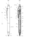
- FIG. 1 is a retractable writing instrument according to a first embodiment of the present invention, in which the pen tip is retracted into the barrel.
- FIG. 1A is a side view and FIG. 1B is a sectional view.
- FIG. 2 shows the retractable writing instrument with the pen tip protruding from the barrel.
- 2A is a side view and FIG. 2B is a sectional view.
- FIG. 3 shows a clip body that constitutes a clip of the retractable writing instrument.
- FIG. 3A is a perspective view of the clip body as viewed from above.
- FIG. 3B is a perspective view of the clip body as seen from below.
- FIG. 4 shows a state of the clip body before being assembled to the retractable writing instrument.
- 4A is a plan view
- FIG. 4B is a side view
- FIG. 4C is a bottom view
- FIG. 5 shows a clip base that constitutes a clip of the retractable writing instrument.
- 5A is a front view
- FIG. 5B is a side view
- FIG. 5C is a plan view
- FIG. 5D is a bottom view
- FIG. 5E is a rear view
- FIG. 5F is a sectional view taken along the line AA of FIG. 5B
- FIG. 5G is B of FIG. 5B.
- FIG. 6 is a sectional view taken along line B-.
- FIG. 6 shows a state of the clip body after being assembled to the retractable writing instrument.
- 6A is a side sectional view of a rear portion of the retractable writing instrument including the clip body
- FIG. 6A is a side sectional view of a rear portion of the retractable writing instrument including the clip body
- FIG. 6B is a side view of the clip body
- FIG. 6C is a sectional view of the clip body.
- FIG. 7 shows an intermediate shaft that constitutes the retractable writing instrument.
- 7A is a perspective view of a rear portion of the intermediate shaft
- FIG. 7B is a sectional view of a process of assembling the clip on the intermediate shaft.
- FIG. 8 shows a clip body that constitutes a clip of the retractable writing instrument according to the second embodiment of the present invention.
- 8A is a sectional view
- FIG. 8B is a bottom view
- FIG. 8C is a perspective view of the clip body as seen from below.
- FIG. 9 shows the unintended connection of two clip bodies without stopper walls.
- 9A is a sectional view
- FIG. 9B is a bottom view
- FIG. 9C is a perspective view of the two clip bodies as seen from below.
- FIG. 10 shows a state in which the two clip bodies having the stopper walls are prevented from being combined.
- 10A is a cross-sectional view
- FIG. 10B is a bottom view
- FIG. 10C is a perspective view of the two clip bodies as seen from below.
- FIG. 11 shows an unintended connection state of two clip bodies having no wide portion in the grip portion.
- FIG. 11A is a cross-sectional view showing a first example in an unintended combined state
- FIG. 11B is a perspective view showing another second example in the unintentional combined state.
- FIG. 11A is a cross-sectional view showing a first example in an unintended combined state
- FIG. 11B is a perspective view showing another second example in the unintentional combined state.
- FIG. 11A is a cross-sectional view showing a first example in an unintended combined state
- FIG. 12A is a cross-sectional view showing a clip body that constitutes a clip of a retractable writing instrument according to a third embodiment of the present invention.
- FIG. 12B is a cross-sectional view showing a clip body that constitutes a clip of the retractable writing instrument according to the fourth embodiment of the present invention.
- FIG. 12C is a cross-sectional view showing a clip body that constitutes a clip of a retractable writing instrument according to a fifth embodiment of the present invention.
- FIG. 13A is a cross-sectional view showing a clip body that constitutes a clip of a retractable writing instrument according to a sixth embodiment of the present invention.
- FIG. 12A is a cross-sectional view showing a clip body that constitutes a clip of a retractable writing instrument according to a sixth embodiment of the present invention.
- FIG. 13B is a cross-sectional view showing a clip body that constitutes a clip of the retractable writing instrument according to the seventh embodiment of the present invention.
- FIG. 14 shows an intermediate shaft that constitutes the retractable writing instrument of the first embodiment.
- FIG. 14A is a perspective view of a rear portion of the intermediate shaft.
- FIG. 14B is a plan view of a rear portion of the intermediate shaft.
- FIG. 15 shows the internal structure of the retractable writing instrument of the first embodiment.
- FIG. 15A is a cross-sectional view showing a protruding state of the pen tip.
- FIG. 15B is a cross-sectional view showing the pen tip in the retracted state.
- FIG. 16 shows an intermediate shaft constituting a retractable writing instrument according to the eighth embodiment of the present invention.
- FIG. 16 shows an intermediate shaft constituting a retractable writing instrument according to the eighth embodiment of the present invention.
- FIG. 16A is a perspective view of a rear portion of the intermediate shaft.
- FIG. 16B is a plan view of a rear portion of the intermediate shaft.
- FIG. 16C is a sectional view of a process of assembling the clip on the intermediate shaft.
- FIG. 17 shows the internal structure of the retractable writing instrument of the eighth embodiment.
- FIG. 17A is a cross-sectional view showing a protruding state of the pen tip.
- FIG. 17B is a cross-sectional view showing the pen tip in a retracted state.
- FIG. 18A is an enlarged view of FIG. 17A.
- FIG. 18B is an enlarged view of FIG. 17B.
- FIG. 19 shows an intermediate shaft which constitutes a retractable writing instrument according to the ninth embodiment of the present invention.
- FIG. 19 shows an intermediate shaft which constitutes a retractable writing instrument according to the ninth embodiment of the present invention.
- FIG. 19 shows an intermediate shaft which constitutes a retractable writing instrument according to the ninth embodiment of the
- FIG. 19A is a perspective view of a rear portion of the intermediate shaft.
- FIG. 19B is a plan view of a rear portion of the intermediate shaft.
- FIG. 19C is a sectional view of a process of assembling the clip on the intermediate shaft.
- FIG. 20 shows the internal structure of the retractable writing instrument of the first embodiment.
- FIG. 20A is a sectional view showing a protruding state of the pen tip.
- FIG. 20B is a cross-sectional view showing the pen tip in a retracted state.
- FIG. 21A is a plan view showing a rear side portion of the intermediate shaft which constitutes the retractable writing instrument according to the tenth embodiment of the present invention.
- FIG. 21B is a plan view showing a rear side portion of the intermediate shaft which constitutes the retractable writing instrument according to the eleventh embodiment of the present invention.
- thermochromic writing instrument that can change the handwriting of the thermochromic ink by frictional heat is used as the retractable writing instrument.
- the structure of the present invention is not limited to the thermochromic writing instrument, but can be widely applied to general retractable writing instruments.
- FIGS. 1A, 1B, 2A and 2B The configuration of the retractable writing apparatus 1 according to the first embodiment of the present invention is shown in FIGS. 1A, 1B, 2A and 2B.
- the double-headed arrow in the figure defines the "front” and “rear” of the retractable writing instrument 1.
- the retractable writing instrument 1 includes a barrel 2, a rotating member 3, a clip 4, a spring 5, a writing body 6 and a friction portion 7.
- the barrel 2 is composed of a base 21, a front shaft 22, an intermediate shaft 23, and a rear shaft 24.
- An elastic grip 22 a is attached to the outer peripheral surface of the front shaft 22.
- the friction body 7 is fitted in the mounting hole 24b (see FIG. 6A) of the rear shaft 24.
- the clip 4 is composed of a clip body 41 and a clip base 43.
- the mouthpiece 21 and the clip body 41 are made of metal, and the other components are made of synthetic resin.
- the metal mouthpiece 21 and the clip body 41 are remarkably different in texture and appearance from the synthetic resin barrel 2, which is a feature that attracts the line of sight of the user.
- the surface of the barrel 2 made of synthetic resin, for example, the surface of the intermediate shaft 23 is decorated by attaching a transfer film.
- the spring 5, the writing body 6, the rotating member 3, and the cylindrical portion 43d of the clip base 43 are sequentially housed in the barrel 2.
- the cursive body 6 includes a pen tip 61, an ink containing tube 62, a thermochromic ink 63, a follower 64, and a tail plug 65.
- the pen tip 61 is attached to the front end of the ink containing tube 62.
- the pen tip 61 of the present embodiment is a ballpoint pen tip, but the configuration of the present invention is not limited to a ballpoint pen, and can be widely applied to retractable writing instruments such as mechanical pencils and marking pens. is there.
- the thermochromic ink 63 and the follower 64 are filled inside the ink containing tube 62.
- the tail plug 65 is attached to the opening at the rear end of the ink containing tube 62.
- thermochromic ink 63 A vent hole extending in the front-rear direction is provided at the center of the tail plug 65.
- the handwriting formed on the paper surface with the thermochromic ink 63 can be thermally discolored by the friction portion 7.
- the friction part 7 generates frictional heat by being rubbed against the paper surface. Due to this frictional heat, the handwriting of the thermochromic ink 63 is thermally discolored.
- the thermochromic ink 63 is, for example, thermochromically changed from the first colored to the second colored, or from the colored to colorless.
- the pen tip 61 of the cursive body 6 is in a state of protruding from the barrel 2 or being immersed in the barrel 2 by the retracting mechanism.
- the retracting mechanism is composed of a spring 5, a rotating member 3, a clip base 43, and a slide hole 20, a cam tooth 23a, and a cam groove 23b provided in a wall of the shaft cylinder 2 (Fig. 6A).
- the spring 5 is attached to the front end of the cursive body 6 and constantly biases the cursive body 6 backward.
- the rotating member 3 and the clip base 43 are arranged behind the cursive body 6.
- the rotating member 3 is rotatably coupled to the cylindrical portion 43d of the clip base 43.
- the rotating member 3 includes four protrusions 31.
- the four ridges 31 are evenly provided on the outer surface of the rotating member 3 at intervals of 90°.
- the ridge 31 continues from the side surface of the rotating member 3 to the upper surface.
- the rear end portion of the protrusion 31 protruding from the upper surface of the rotating member 3 is an inclined surface (cam tooth) inclined in one direction.
- the clip base 43 is slidable in the front-rear direction along the slide hole 20 provided on the rear side of the barrel 2.
- the clip base 43 includes a slider 43a, a connecting portion 43c, and a cylindrical portion 43d (see FIG. 5B).
- the slider 43 a is located outside the barrel 2.
- the cylindrical portion 43d is located inside the barrel 2.
- the rear side of the clip body 41 is coupled to the slider 43a.
- the connecting portion 43c connects the slider 43a and the cylindrical portion 43d via the slide hole 20 of the shaft tube 2.
- Cam teeth 43e are provided at the front end of the cylindrical portion 43d (see FIG. 5B).
- the cam teeth 43e of the cylindrical portion 43d mesh with the rear end portion of the protrusion 31 of the rotating member 3.
- cam teeth 23a and cam grooves 23b are provided on the inner wall surface of the shaft tube 2.
- the cam teeth 23a and the cam grooves 23b alternately mesh with the protrusions 31 of the rotating member 3.
- the pen tip 61 of the writing body 6 is brought into a protruding state or a depressed state. That is, the user of the retractable writing instrument 1 slides the slider 43 a of the clip base 43 along with the clip body 41 forward along the slide hole 20 of the barrel 2. Then, in the shaft cylinder 2, the rotating member 3 is pushed by the cylindrical portion 43b of the clip base 43 and moves forward of the cam teeth 23a and the cam groove 23b.
- the rotary member 3 rotates in one direction, and the protrusion 31 meshes with either the cam tooth 23a or the cam groove 23b.
- the rotation member 3 is held while moving forward by the protrusions 31 meshing with the cam teeth 23a.
- the pen tip 61 of the writing body 6 is in a state of protruding from the front end hole 21 a of the barrel 2.
- the rotary member 3 moves rearward along the cam groove 23b.
- the pen tip 61 of the writing body 6 is in a state of being immersed in the barrel 2.
- the retractable writing instrument 1 of this embodiment is characterized by the configuration of the clip 4.
- the clip 4 of this embodiment includes a clip body 41 and a clip base 43 shown in FIG. 6A.
- a grip portion 42 is integrally provided at the front end of the clip body 41.
- the grip 42 generates an elastic force for gripping an object.
- FIGS. 3A, 3B, and 4A to 4C The configurations of the clip body 41 and the grip portion 42 of this embodiment are shown in FIGS. 3A, 3B, and 4A to 4C.
- the clip body 41 and the grip portion 42 are integrally formed by bending a single metal plate.
- the fixed end 42a shown in FIGS. 3B and 4C serves as a boundary between the clip body 41 and the grip portion 42.
- the clip body 41 forms the main appearance of the clip 4 with the fixed end 42a as a boundary.
- the grip 42 uses the fixed end 42a as a fulcrum to generate an elastic force for gripping an object.
- the clip main body 41 includes one upper wall 41a and a pair of side walls 41b.
- the upper wall 41 a extends in the front-back direction of the barrel 2.
- the pair of side walls 41b are formed by vertically bending metal plates continuous on both sides of the upper wall 41a.
- the pair of side walls 41b reaches the rear end from the front end of the upper wall 41a and further extends rearward.
- the edges of the metal plate forming the pair of side walls 41b face the transfer film attached to the surface of the barrel 2, that is, the surface of the intermediate shaft 23.
- the clip 4 of the present embodiment is configured such that an object having a thickness equal to or smaller than the clearance CL in FIG. 6A is gripped by the grip portion 42, and an object having a thickness exceeding the clearance CL is gripped by the clip body 41. ..
- the grip portion 42 is flexibly deformed to generate an elastic force, and an object having a thickness equal to or smaller than the clearance CL is gripped by the elastic force.
- the clip body 41 has a box shape surrounded by a wall of a metal plate and has high rigidity. Such a clip body 41 is slightly bent as a whole to sandwich an object having a thickness exceeding the clearance CL. Therefore, the outer shape of the clip body 41 can be designed without considering the elastic force for gripping an object. That is, the clip body 41 of the present embodiment has a high degree of freedom in designing the outer shape.
- the upper wall 41a has the narrowest width at the front end and gradually widens from the front side to the rear side. Further, as shown in FIG. 4B, the upper wall 41a curves gently from the front end to the rear end.
- the front side of the side wall 41b is designed in the shape of a gently curved ball portion. The height of the wall at the center of the side wall 41b is lower than that of the other portions, and gives the impression that the center of the clip body 41 flexes flexibly.
- the rear side of the side wall 41b is designed as a substantially parallelogram formed of straight lines, symmetrically with the front side formed of a curve.
- a pair of engaging portions 41c protruding toward the inside of the clip body 41 is formed on the rear side of the pair of side walls 41b. Further, as shown in FIG. 3B, a pair of stopper walls 41d protruding toward the back surface of the upper wall 41a are formed at the front ends of the pair of engaging portions 41c.
- a pair of engagement grooves 43b are provided on both sides of the slider 43a of the clip base 43. As shown in FIG. 6A, the pair of engaging portions 41c of the clip body 41 engages with the pair of engaging grooves 43b of the slider 43a. At this time, the pair of stopper walls 41d come into contact with the front surface of the slider 43a.
- the gripping part 42 is provided on the back side of the clip main body 41 and between the pair of side walls 41b. More specifically, the grip portion 42 is located between the front side portions of the pair of side walls 41b that are designed in the shape of a ball.
- the grip 42 is formed by bending a part of the same metal plate as the clip body 41.
- the grip 42 of this embodiment includes a beam 42b and a protrusion 42c that are continuous with each other.
- the beam 42b extends horizontally from the fixed end 42a to the rear of the barrel 2 (see FIG. 8A).
- the protrusion 42 c is bent in a V shape from the beam 42 b and protrudes toward the surface of the barrel 2.
- the top of the protrusion 42c is preferably located on a straight line passing through the highest part of the pair of side walls 41b forming the ball.
- the black dot in FIG. 4B indicates the highest portion of the pair of side walls 41b.
- the alternate long and short dash line in FIG. 4B indicates a straight line passing through the highest part of the pair of side walls 41b.
- the top of the protrusion 42c of the present embodiment is located on the alternate long and short dash line passing through the black dot in FIG. 4B.
- the rear end of the protrusion 42c is a free end 42d. Before the clip body 41 is assembled to the retractable writing instrument 1, the free end 42d of the protrusion 42c does not contact the back surface of the upper wall 41a of the clip body 41 (see FIG. 8A).
- the protrusion 42c has a width W1 that can be accommodated in the guide groove 23f of the barrel 2 shown in FIG. 7A.
- the width W1 from the front side to the rear end of the V-shaped protrusion 42c is narrower than the width W3 of the beam 42b (W1 ⁇ W3).
- the width W1 of the protrusion 42c is slightly narrower than the width W2 of the guide groove 23f of the barrel 2.
- the dimensional difference between the width W2 of the guide groove 23f and the width W1 of the protrusion 42c is preferably within the range of 0.1 mm ⁇ W2-W1 ⁇ 4.0 mm.
- the protrusion 42c is housed between the pair of side surfaces 234 of the guide groove 23f, and moves in the front-rear direction of the barrel 2 along the guide groove 23f.
- the protrusion 42c does not come into contact with any part of the shaft tube 2 other than the guide groove 23f.
- the width W1 of the protrusion 42c is preferably wider than 20% of the width W3 of the beam 42b in order to obtain sufficient strength (W3 ⁇ 0.2 ⁇ W1).
- the grip portion 42 of the present embodiment is configured to generate a two-step elastic force according to the thickness of the object to be gripped.
- the elastic force in the first stage is generated by the deformation of the beam 42b with the fixed end 42a shown in FIG. 6C as the fulcrum.
- FIG. 6A when the clip body 41 is assembled to the retractable writing instrument 1, the beam 42b deforms toward the back surface of the upper wall 41a of the clip body 41 with the fixed end 42a as a fulcrum.
- the protrusion 42c exerts a first-stage elastic force on the guide groove 23f of the shaft cylinder 2 (see the protrusion amounts AM1 and AM2 shown in FIGS. 4B and 6B).
- the protrusion 42c constantly applies a load of 200 gf to the guide groove 23f of the barrel 2.
- the elastic force in the second stage is generated when the protrusion 42c shown in FIG. 6C is deformed with its top as a fulcrum. That is, when the beam 42b is further deformed with the fixed end 42a as a fulcrum in the state where the elastic force of the first stage is generated, the free end 42d of the protrusion 42c contacts the back surface of the upper wall 41a of the clip body 41. As a result, the protrusion 42c is deformed with its top as a fulcrum to generate a second-stage elastic force.
- the grip portion 42 of the present embodiment grips a thin object by the elastic force of the first step (for example, 200 gf), and a thick object by the elastic force (for example, over 200 gf) that is the sum of the first step and the second step. Hold it.
- the clip base 43 includes the slider 43a, the connecting portion 43c, and the cylindrical portion 43d.
- the slider 43a is provided with a pair of engagement grooves 43b.
- the pair of engaging grooves 43b engage with the pair of engaging portions 41c of the clip body 41.
- Cam teeth 43e are provided at the front end of the cylindrical portion 43d. The cam teeth 43e mesh with the rear end portion of the protrusion 31 of the rotating member 3.
- the clip base 43 of the present embodiment supports the clip body 41 coupled to the slider 43a at a predetermined height so that the surface of the barrel 2 is not damaged.
- the clip base 43 supports the clip body 41 at a height such that the pair of side walls 41b do not contact the surface of the barrel 2 and the grip 42 contacts the bottom surface 233 of the guide groove 23f.
- the clearance CL shown in FIG. 6A is maintained between the pair of side walls 41b and the surface of the barrel 2.
- the clearance CL is maintained by the height at which the clip base 43 supports the clip body 41.
- the clearance CL is maintained by the elastic force (for example, 200 gf) of the grip portion 42 generated when the clip body 41 is assembled to the retractable writing instrument 1.
- the guide groove 23f described above is provided on the rear side of the intermediate shaft 23 that constitutes the shaft cylinder 2.
- the guide groove 23f is a groove extending in the front-rear direction of the barrel 2 and is composed of a bottom surface 233 and a pair of side surfaces 234. As shown in FIG. 6A, the bottom surface 233 of the guide groove 23f comes into contact with the protruding portion 42c forming the grip portion 42 of the clip 4.
- the pair of side surfaces 234 of the guide groove 23f limits the lateral movement of the protrusion 42c.
- the guide groove 23f having such a structure guides the clip 4, which is slid for retracting the pen tip 61, in the front-rear direction of the barrel 2 and moves it in a straight line.
- the surface of the intermediate shaft 23 is decorated by attaching the transfer film, but the transfer film is not attached to the guide groove 23f.
- the guide groove 23f of the present embodiment has a total length exceeding the length required for sliding the clip 4.
- the guide groove 23f includes a first region 231 on the front side and a second region 232 on the rear side.
- the second region 232 communicates with the front end of the first elongated hole 23e provided on the rear side of the intermediate shaft 23.
- the first elongated hole 23e constitutes the slide hole 20 together with the second elongated hole 24a of the rear shaft 24 shown in FIG. 2B.
- the first area 231 of the guide groove 23f is used for sliding the clip 4 for retracting the pen tip 61. That is, when the pen tip 61 is projected and retracted, the clip 4 is moved in the front-back direction within the range of the length of the first region 231.
- the second region 232 of the guide groove 23f is used when the clip 4 is assembled to the intermediate shaft 23.
- the clip 4 is assembled by inserting the cylindrical portion 43d of the clip base 43 into the inside of the intermediate shaft 23.
- the protrusion 42c forming the grip 42 of the clip 4 passes through the first elongated hole 23e and moves from the second region 232 of the guide groove 23f to the first region 231. Be guided.
- the clip 4 can be assembled to the intermediate shaft 23 without the metal protrusion 42c coming into contact with the surface of the intermediate shaft 23.
- the clip 4 of the present embodiment can be made of a metal plate and can be adjusted to an appropriate elastic force that does not damage thin paper or cloth. That is, the metal clip 4 is composed of the clip body 41 and the grip portion 42.
- the outer appearance of the clip 4 is formed by the outer shape of a box-shaped clip body 41 surrounded by a plurality of walls.
- the elastic force of the clip 4 is generated by the grip portion 42 provided on the back side of the clip body 41.
- the configuration of the grip portion 42 does not affect the appearance of the clip 4. Therefore, the grip portion 42 can be freely configured to generate an appropriate elastic force.
- the outer shape of the clip body 41 can be designed with little consideration given to the elastic force for gripping an object, and the degree of freedom in design is high.
- the clip 4 of this embodiment does not damage the surface of the barrel 2 by the edge of the metal plate.
- the clearance CL shown in FIG. 6A is maintained between the metal clip body 41 and the surface of the barrel 2 to which the transfer film is attached. This prevents the pair of side walls 41b of the clip body 41 from contacting the surface of the barrel 2.
- the metal grip portion 42 contacts only the guide groove 23f to which the transfer film is not attached, and does not contact the surface of the barrel 2 to which the transfer film is attached. With the above configuration, the metal clip 4 does not contact and damage the surface of the barrel 2.
- the clip 4 of the present embodiment can prevent contact between the metal clip 4 and the surface of the barrel 2 without providing a protrusion on the surface of the barrel 2 as in the conventional case. Therefore, the transfer film can be efficiently attached to the surface of the barrel 2.
- the grip portion 42 always exerts an elastic force on the guide groove 23f of the shaft tube 2.
- the elastic force of the grip portion 42 always suppresses the rattling of the clip 4.
- the operability of the clip 4 is improved. That is, the rattling-free clip 4 can be slid straight along the slide hole 20 and the guide groove 23f.
- generation of unpleasant sound or vibration due to rattling of the clip 4 is prevented.
- rattling of the clip 4 during writing by the retractable writing instrument 1 is suppressed, and the usability of the retractable writing instrument 1 is improved.
- the pair of stopper walls 41d provided on one clip body 41 prevent unintended coupling of the two clip bodies 41.
- the automatic assembly of the retractable writing instrument 1 can be smoothly performed.
- the prevention of unintended coupling of the two clip bodies 41 will be described in detail in the second embodiment below.
- the pair of stopper walls 41d shown in FIGS. 8A to 8C and one wide portion 42e Unintentional coupling of the two clip bodies 41 is prevented by the pair of stopper walls 41d shown in FIGS. 8A to 8C and one wide portion 42e.
- the configuration of the pair of stopper walls 41d has already been described in the first embodiment.
- the pair of stopper walls 41d are formed at the front ends of the pair of engaging portions 41c and project toward the back surface of the upper wall 41a.
- the wide portion 42e is provided at the rear end portion including the free end 42d of the grip portion 42.
- the width W4 of the wide portion 42e is at least wider than the width W1 of the protruding portion 42c, and preferably has a width that is 1 ⁇ 2 or more of the distance between the pair of side walls 41b of the clip body 41.
- the width W4 of the wide portion 42e of the present embodiment has substantially the same size as the width W3 of the beam 42, but may exceed the width W3 of the beam 42 (
- FIGS. 9A to 9C show two clip bodies 41 without the stopper wall 41d and the wide portion 42e.
- the configuration of the clip body 41 is the same as the clip body 41 of the first embodiment shown in FIGS. 4A to 4C, except that the stopper wall 41d is not provided.
- the clip body 41 has an outer shape in which the width of the front end is the smallest and the width gradually increases from the front side to the rear side. Further, as shown in FIGS. 9A and 9C, the rear end opening of the clip body 41 is surrounded by the upper wall 41a, the pair of side walls 41b, and the pair of engaging portions 41c. Therefore, the narrow front side of one clip body 41 may be deeply fitted to the wide rear side of the other clip body 41. The automatic assembly machine cannot separate the two fitted clip bodies 41. Therefore, the automatic assembly of the retractable writing instrument 1 is temporarily stopped.
- 10A to 10C show two clip bodies 41 provided with a pair of stopper walls 41d.
- the pair of stopper walls 41d provided on one clip body 41 abut on the front ends of the other clip bodies 41 and prevent the one and the other clip bodies 41 from fitting.
- the plurality of clip bodies 41 are separately supplied to the automatic assembly machine, and the automatic assembly of the retractable writing instrument 1 is smoothly performed.
- the grip portions 42 of the two clip bodies 41 not provided with the wide portion 42e may be entangled with each other.
- the automatic assembly machine cannot separate the two clip bodies 41 in which the grips 42 are intertwined. Therefore, the automatic assembly of the retractable writing instrument 1 is temporarily stopped.
- the wide portion 42e shown in FIGS. 8A to 8C the entanglement between the grip portions 42 of the two clip bodies 41 is reduced. That is, the wide portion 42e has a width that is 1 ⁇ 2 or more of the distance between the pair of side walls 41b of the clip body 41. Therefore, the wide portion 42e of the one clip body 41 is unlikely to enter the gap between the grip portions 42 of the other clip bodies 41. As a result, the entanglement between the grips 42 is reduced. According to such a wide portion 42e, the plurality of clip bodies 41 are separately supplied to the automatic assembly machine, and the automatic assembly of the retractable writing instrument 1 is smoothly performed.
- the protruding portion 42c when the free end 42d contacts the back surface of the upper wall 41a of the clip body 41, the protruding portion 42c is deformed with its top as a fulcrum, and a second-stage elastic force is generated.
- the wide portion 42e suppresses rattling of the protrusion 42c and stabilizes the deformation of the protrusion 42c when the elastic force of the second stage is generated.
- the above-described technical effect of the wide portion 42e becomes more remarkable as the width W4 of the wide portion 42e becomes wider. That is, the wider the width W4 of the wide portion 42e, the more reliably the entanglement between the gripping portions 42 of the two clip bodies 41 is prevented. Further, the wider the width W4 of the wide portion 42e, the less rattling of the protruding portion 42c, and the more stable the deformation of the protruding portion 42c when the elastic force of the second stage is generated.
- the configuration of the gripping part 42 of the clip body 41 is not limited to the V-shape shown in FIGS. 4A to 4C.
- the grip 42 may have the configuration shown in FIGS. 12A to 12C, for example.
- FIG. 12A shows a clip body 41 and a grip portion 42 that constitute a clip of a retractable writing instrument according to a third embodiment of the present invention.
- the clip body 41 and the grip portion 42 are integrally provided by a single metal plate.
- An arcuate protrusion 42f is formed on the grip 42.
- the arc-shaped protrusion 42f protrudes from the beam 42b toward the surface of the barrel 2.
- the radius of curvature R of the top of the protrusion 42f is preferably larger than 0.5 mm, more preferably larger than 1.5 mm.
- the rear end of the protrusion 42f is a free end 42d.
- Such an arc-shaped protrusion 42f functions similarly to the V-shaped protrusion 42c shown in FIGS. 4A to 4C.
- the wide portion 42e shown in FIGS. 8A to 8C may be provided at the rear end portion including the free end 42d of the grip portion 42 of the present embodiment.
- FIG. 12B shows a clip body 41 and a grip portion 42 that constitute a clip of a retractable writing instrument according to a fourth embodiment of the present invention.
- the clip body 41 and the grip portion 42 are integrally provided by a single metal plate.
- the grip 42 is formed with a W-shaped protrusion 42g.
- the W-shaped protrusion 42g protrudes from the beam 42b toward the surface of the barrel 2.
- the W-shaped protrusion 42g has two tops. The boundary between the two peaks of the protrusion 42g is the lowest valley. It is preferable that the valleys of the protrusions 42g be located on a straight line passing through the highest part of the pair of side walls 41b forming the ball.
- FIG. 12B indicates the highest portion of the pair of side walls 41b.
- the alternate long and short dash line in FIG. 12B indicates a straight line passing through the highest part of the pair of side walls 41b.
- the valley portion of the protrusion 42g of the present embodiment is located on the alternate long and short dash line passing through the black dot in FIG. 12B.
- the rear end of the protrusion 42g is a free end 42d.
- Such a W-shaped protrusion 42g functions similarly to the V-shaped protrusion 42c shown in FIGS. 4A to 4C.
- the wide portion 42e shown in FIGS. 8A to 8C may be provided at the rear end portion including the free end 42d of the grip portion 42 of the present embodiment.
- FIG. 12C shows a clip body 41 and a grip portion 42 that constitute a clip of a retractable writing instrument according to a fifth embodiment of the present invention.
- the clip body 41 and the grip portion 42 are integrally provided by a single metal plate.
- An inverted trapezoidal protrusion 42h is formed on the grip 42.
- the inverted trapezoidal protrusion 42h protrudes from the beam 42b toward the surface of the barrel 2.
- the rear end of the protrusion 42h is a free end 42d.
- Such an inverted trapezoidal protrusion 42h functions similarly to the V-shaped protrusion 42c shown in FIGS. 4A to 4C.
- the wide portion 42e shown in FIGS. 8A to 8C may be provided at the rear end portion including the free end 42d of the grip portion 42 of the present embodiment.
- the clip main body 41 and the gripping part 42 are not limited to the configuration integrally provided by a single metal plate.
- the clip body 41 and the grip 42 may have the configuration shown in FIGS. 13A and 13B, for example.
- FIG. 13A shows a clip main body 41 and a grip portion 44 that constitute a clip of a retractable writing instrument according to a sixth embodiment of the present invention.
- the clip body 41 is configured by bending a single metal plate.
- the grip portion 44 is integrally formed of synthetic resin.
- the synthetic resin gripping portion 44 has a fixed point 44a, a beam 44b, a protrusion 44c, and a free end 44d similar to the gripping portion 42 shown in FIGS. 4A to 4C.
- the synthetic resin grip portion 44 is fixed to the back surface of the upper wall 41a of the metal clip body 41.
- the grip portion 44 is fixed to the back surface of the upper wall 41a, for example, by adhesion or fitting.
- Such a synthetic resin gripping portion 44 functions similarly to the metal gripping portion 42 shown in FIGS. 4A to 4C.
- FIG. 13B shows a clip body 45 and a grip portion 42 that constitute a clip of a retractable writing instrument according to a seventh embodiment of the present invention.
- the clip body 45 is integrally molded of synthetic resin.
- the grip portion 42 is configured by bending a single metal plate.
- the clip body 45 made of synthetic resin has an upper wall 45a, a pair of side walls 45b, and a pair of engaging portions 45c similar to the clip body 41 shown in FIGS. 4A to 4C.
- the metal grip 42 is fixed to the back surface of the upper wall 45a of the clip body 45 made of synthetic resin.
- the grip portion 42 is fixed to the back surface of the upper wall 45a by, for example, bonding or fitting. Such a metal gripping portion 42 functions similarly to the metal gripping portion 42 shown in FIGS. 4A to 4C.
- the guide groove 23f provided on the intermediate shaft 23 is not limited to the configuration shown in FIGS. 7A and 7B of the first embodiment described above.
- the guide groove 23f of the first embodiment includes first and second regions 231 and 232.
- the first area 231 is used for sliding the clip 4 for retracting the pen tip 61 (see FIGS. 1B and 2B). That is, when the pen tip 61 is projected and retracted, the clip 4 is moved in the front-back direction within the range of the length of the first region 231.
- FIGS. 15A and 15B show the internal configuration of the retractable writing instrument 1 according to the first embodiment.
- FIG. 15A shows a state in which the pen tip 61 projects from the barrel 2.
- FIG. 15B shows a state in which the pen tip 61 is immersed in the barrel 2.
- the grip portion 42 of the clip 4 is located in the front half portion 231a of the first area 231.
- FIG. 15B when the pen tip 61 is in the state of being retracted into the barrel 2, the grip portion 42 of the clip 4 is located in the second half portion 231b of the first area 231.
- the guide groove 23f of the first embodiment has a bottom surface 233 in the latter half portion 231b of the first region 231. For this reason, the movement of the clip 4 to the rear rarely stops immediately before the pen tip 61 enters the completely immersed state shown in FIG. 15B. That is, the retractable writing instrument 1 according to the first embodiment has a technical problem that the normal operation of the clip 4 for putting the pen tip 61 into the retracted state is not reliably performed.
- FIGS. 15A and 15B causes of such technical problems will be described with reference to FIGS. 15A and 15B.
- the clip 4 is slid to the rear of the barrel 2 by the biasing force P1 of the spring 5 (see FIGS. 1B and 2B) attached to the front end of the writing body 6.
- the grip portion 42 of the clip 4 causes the elastic force P2 to the bottom surface 233 of the guide groove 23f.
- the clip 4 receives a reaction force (see the gray arrow in FIGS. 15A and 15B) opposite to the elastic force P2 from the bottom surface 233.
- the clip 4 is tilted with the clip base 43 as a fulcrum by the reaction force in the direction opposite to the elastic force P2.
- the clip base 43 in the tilted state is pressed against the surface and the inner surface of the intermediate shaft 23 and the rear shaft 24 to generate frictional resistance (see a portion surrounded by a chain line in FIGS. 15A and 15B).
- the frictional resistance of the clip base 43 has a preferable effect of suppressing rattling of the clip 4.
- the frictional resistance of the clip base 43 causes a problem of stopping the rearward movement of the clip 4 immediately before the pen tip 61 is in the fully retracted state shown in FIG. 15B.
- the elastic force P2 of the grip 42 is not the only cause of stopping the rearward movement of the clip 4.
- the change in the biasing force P1 depending on the expansion and contraction of the spring 5 also causes the movement of the clip 4 to the rear to be stopped. That is, the urging force P1 of the spring 5 increases as the spring 5 is compressed and decreases as the spring 5 extends. Therefore, the urging force P1 of the spring 5 is maximum in the protruding state of the pen tip 61 shown in FIG. 15A, and is minimum in the retracted state of the pen tip 61 shown in FIG. 15B.
- FIGS. 16 to 18 a retractable writing instrument according to an eighth embodiment of the present invention will be described with reference to FIGS. 16 to 18.
- the retractable writing instrument according to the eighth embodiment is provided with a configuration for solving the problem that the backward movement of the clip 4 is stopped.
- FIGS. 16A, 16B and 16C show the intermediate shaft 23 of the retractable writing instrument according to the eighth embodiment.
- the retractable writing instrument according to the eighth embodiment is characterized by the configuration of the guide groove 23f provided on the intermediate shaft 23.
- the guide groove 23f includes a bottom surface 233, a pair of side surfaces 234, and a through groove 235.
- the bottom surface 233 of the guide groove 23f is not an essential component, but is formed in a portion of the guide groove 23f other than the latter half portion 231b of the first region 231.
- the bottom surface 233 is formed on the front half portion 231a of the first region 231.
- the bottom surface 233 has substantially the same length as the front half portion 231a.
- the bottom surface 233 of this embodiment has a length slightly shorter than the entire length of the front half portion 231a of the first region 231. That is, as shown in FIG. 17A, the bottom surface 233 has a minimum length that allows the bottom surface 233 to come into contact with the protruding portion 42c forming the grip portion 42 of the clip 4 when the pen tip 61 is in the protruding state. There is.
- the through groove 235 of the guide groove 23f is formed at least in the second half portion 231b of the first region 231.
- the through groove 235 of the present embodiment is formed over the entire first region 231 to the second region 232 except the bottom surface 233, and is continuous with the first elongated hole 23e.
- the projecting portion 42c forming the gripping portion 42 of the clip 4 is the front half portion of the first region 231 of the guide groove 23f. Located at 231a.
- the grip portion 42 of the clip 4 causes the elastic force P2 to the bottom surface 233 of the guide groove 23f.
- the clip 4 receives a reaction force (see the gray arrow in FIG. 17A) opposite to the elastic force P2 from the bottom surface 233.
- the clip 4 is tilted with the clip base 43 as a fulcrum by the reaction force in the direction opposite to the elastic force P2.
- the clip base 43 in the inclined state is pressed against the surface and the inner surface of the intermediate shaft 23 and the rear shaft 24 to generate frictional resistance (see a portion surrounded by a chain line in FIG. 17A).
- the frictional resistance of the clip base 43 has a preferable effect of suppressing rattling of the clip 4. That is, the bottom surface 233 formed in the front half portion 231a of the first area 231 of the guide groove 23f prevents the clip 4 from rattling when the pen tip 61 is in the protruding state.
- the protruding state of the pen tip 61 shown in FIG. 17A shifts to the retracted state of the pen tip 61 shown in FIG. 17B by sliding the clip 4 in front of the barrel 2 (see FIG. 2A). ..
- the clip 4 is moved by the urging force P1 of the spring 5 (see FIGS. 1B and 2B) attached to the front end portion of the writing body 6 of the barrel 2. It is slid backward.
- the protruding portion 42c forming the grip portion 42 of the clip 4 passes through the boundary between the front half portion 231a and the rear half portion 231b in the first region 231 of the guide groove 23f. At a position to be inserted into the through groove 235 from above the bottom surface 233. After that, the grip portion 42 of the clip 4 moves along the through groove 235 to the boundary between the second half 231b of the first region 231 and the second region 232. This brings the pen tip 61 into the completely immersed state shown in FIG. 17B.
- the grip portion 42 of the clip 4 causes the elastic force P2 until the pen tip 61 moves from the protruding state to the retracted state. Disappear.
- the reaction force in the opposite direction to the elastic force P2 becomes zero, and the frictional resistance of the clip base 43 also becomes zero. Therefore, according to the guide groove 23f of the present embodiment, the rearward movement of the clip 4 is not stopped immediately before the pen tip 61 is in the completely retracted state shown in FIG. 17B. That is, in the retractable writing instrument according to the present embodiment, the normal operation of the clip 4 for putting the pen tip 61 into the retracted state is reliably performed.
- the through groove 235 formed in the second region 232 of the guide groove 23f is used when the clip 4 is assembled to the intermediate shaft 23.
- the protruding portion 42c forming the grip portion 42 of the clip 4 passes through the first elongated hole 23e and the through groove formed in the second region 232 of the guide groove 23f. It is guided to the first region 231 by 235.
- the clip 4 can be assembled to the intermediate shaft 23 without the metal protrusion 42c coming into contact with the surface of the intermediate shaft 23.
- an inclined surface 233a that descends toward the through groove 235 is formed at the rear end of the bottom surface 233 of the guide groove 23f.
- an inclined surface 233a it becomes possible for the protruding portion 42c forming the grip portion 42 of the clip 4 to smoothly move up and down on the bottom surface 233.
- the sliding operation of the clip 4 for retracting the pen tip 61 becomes smooth.
- a gap D is formed between the rear end of the bottom surface 233 of the guide groove 23f and the protruding portion 42c of the clip 4 when the pen tip 61 is retracted. .. Due to the distance D, the protruding portion 42c of the clip 4 enters the through groove 235 and the elastic force P2 of the grip portion 42 becomes zero before the pen tip 61 is in the completely retracted state shown in FIG. 17B.
- the surface of the grip portion 42 does not come into contact with the rear end of the bottom surface 233, and in the process of transition from the protruding state of the pen tip 61 to the retracted state, the surface of the grip portion 42 and the rear end of the bottom surface 233. There is no frictional resistance between them. Due to the technical effect of the distance D, the rearward movement of the clip 4 is more reliably prevented.
- the guide groove 23f of the retractable writing instrument according to the ninth embodiment has a first bottom surface 233A, a through groove 235, and a second bottom surface 233B.
- the first bottom surface 233A is formed in the front half portion 231a of the first region 231 as in the above-described eighth embodiment.
- the second bottom surface 233B is formed in the second region 232.
- the through groove 235 is formed between the first bottom surface 233A and the second bottom surface 233B.
- the through hole 235 of the present embodiment has a length that extends from the rear end of the first bottom surface 233A to the front end of the second bottom surface 233B beyond the boundary between the first region 231 and the second region 232.
- the guide groove 23f of this embodiment also has the same technical effect as that of the above-described eighth embodiment.
- the protrusion 42c of the clip 4 comes into contact with the first bottom surface 233A of the guide groove 23f, so that the grip portion 42 of the clip 4 moves to the guide groove 23f.
- An elastic force P2 is generated on the first bottom surface 233A.
- the clip 4 is tilted with the clip base 43 as a fulcrum by a reaction force (see a gray arrow in FIG. 20A) opposite to the elastic force P2.
- the clip base 43 in the inclined state is pressed against the surface and the inner surface of the intermediate shaft 23 and the rear shaft 24 to generate frictional resistance (see a portion surrounded by a chain line in FIG. 20A).
- the frictional resistance of the clip base 43 has a preferable effect of suppressing rattling of the clip 4.
- the projecting portion 42c of the clip 4 passes through the boundary between the front half portion 231a and the rear half portion 231b in the first region 231 of the guide groove 23f, and is located at the first position. It enters into the through groove 235 from above the bottom surface 233A. After that, the grip portion 42 of the clip 4 moves along the through groove 235 to the boundary between the second half 231b of the first region 231 and the second region 232. This brings the pen tip 61 into the completely immersed state shown in FIG. 20B.
- the grip portion 42 of the clip 4 causes the elastic force P2 until the pen tip 61 moves from the protruding state to the retracted state. Disappear.
- the reaction force in the opposite direction to the elastic force P2 becomes zero, and the frictional resistance of the clip base 43 also becomes zero. Therefore, according to the guide groove 23f of the present embodiment, the rearward movement of the clip 4 is not stopped immediately before the pen tip 61 is in the completely retracted state shown in FIG. 20B. That is, in the retractable writing instrument according to the present embodiment, the normal operation of the clip 4 for putting the pen tip 61 into the retracted state is reliably performed.
- the second region 232 of the guide groove 23f is used when the clip 4 is assembled to the intermediate shaft 23.
- the protruding portion 42c forming the grip portion 42 of the clip 4 passes through the first elongated hole 23e and is moved to the first region 231 by the second region 232 of the guide groove 23f. Be guided.
- the clip 4 can be assembled to the intermediate shaft 23 without the metal protrusion 42c coming into contact with the surface of the intermediate shaft 23.
- the rigidity of the rear portion of the intermediate shaft 23 is improved. That is, the through groove 235 and the first elongated hole 23e are formed in the rear portion of the intermediate shaft 23. As shown in FIG. 16B, when the through groove 235 and the first elongated hole 23e are continuous, the rigidity of the rear side portion of the intermediate shaft 23 is reduced and the intermediate shaft 23 is easily bent.
- the second bottom surface 233B shown in FIG. 19B interrupts the continuity of the through groove 235 and the first elongated hole 23e, and improves the rigidity of the rear portion of the intermediate shaft 23. As a result, the rear portion of the intermediate shaft 23 is less likely to bend, and the transfer film can be efficiently attached to the surface of the intermediate shaft 23.
- FIG. 21A shows the intermediate shaft 23 of the retractable writing instrument according to the tenth embodiment.
- the guide groove 23f of the retractable writing instrument according to the tenth embodiment does not have the bottom surface 233 and is composed of the through groove 235 and the pair of side surfaces 234.
- the through groove 235 of the present embodiment is formed over the entire first region 231 to the second region 232 and is continuous with the first elongated hole 23e.
- the grip portion 42 of the clip 4 does not always generate the elastic force P2 regardless of the state of the pen tip 61.
- the reaction force in the opposite direction to the elastic force P2 becomes zero, and the frictional resistance of the clip base 43 also becomes zero. Therefore, the backward movement of the clip 4 is not stopped. That is, in the retractable writing instrument according to the present embodiment, the normal operation of the clip 4 for putting the pen tip 61 into the retracted state is reliably performed.
- the through groove 235 formed in the second region 232 of the guide groove 23f is used when the clip 4 is assembled to the intermediate shaft 23.
- the protruding portion 42c forming the grip portion 42 of the clip 4 passes through the first elongated hole 23e and the through groove formed in the second region 232 of the guide groove 23f. It is guided to the first region 231 by 235.
- the clip 4 can be assembled to the intermediate shaft 23 without the metal protrusion 42c coming into contact with the surface of the intermediate shaft 23.
- FIG. 21B shows the intermediate shaft 23 of the retractable writing instrument according to the eleventh embodiment.
- the guide groove 23f of the retractable writing instrument according to the eleventh embodiment has only the first region 231 and does not have the second region 232.
- a bottom surface 233 is formed on the first half portion 231a of the first region 231.
- a through groove 235 is formed in the second half 231b of the first region 231.
- the guide groove 23f of this embodiment also has the same technical effect as that of the above-described eighth embodiment.
- the protruding portion 42c of the clip 4 contacts the bottom surface 233 of the guide groove 23f, so that the grip portion 42 of the clip 4 has an elastic force with respect to the bottom surface 233 of the guide groove 23f.
- P2 see FIG. 17A.
- the clip 4 is tilted with the clip base 43 as a fulcrum by the reaction force in the direction opposite to the elastic force P2.
- the clip base 43 in the inclined state is pressed against the surface and the inner surface of the intermediate shaft 23 and the rear shaft 24 to generate frictional resistance.
- the frictional resistance of the clip base 43 has a preferable effect of suppressing rattling of the clip 4.
- the protruding portion 42c of the clip 4 passes through the boundary between the front half portion 231a and the rear half portion 231b in the first region 231 of the guide groove 23f, and the bottom surface 233. From above into the through groove 235. After that, the grip portion 42 of the clip 4 moves to the rear of the latter half portion 231b of the first region 231 along the through groove 235. As a result, the pen tip 61 is completely immersed.
- the grip portion 42 of the clip 4 causes the elastic force P2 until the pen tip 61 moves from the protruding state to the retracted state. Disappear.
- the reaction force in the opposite direction to the elastic force P2 becomes zero, and the frictional resistance of the clip base 43 also becomes zero. Therefore, according to the guide groove 23f of the present embodiment, the backward movement of the clip 4 is not stopped immediately before the pen tip 61 is completely retracted. That is, in the retractable writing instrument according to the present embodiment, the normal operation of the clip 4 for putting the pen tip 61 into the retracted state is reliably performed.
- the guide groove 23f does not have the second region 232, the continuity of the through groove 235 of the first region 231 and the first elongated hole 23e is broken. This improves the rigidity of the rear portion of the intermediate shaft 23. As a result, the rear portion of the intermediate shaft 23 is less likely to bend, and the transfer film can be efficiently attached to the surface of the intermediate shaft 23.
Landscapes
- Clips For Writing Implements (AREA)
- Mechanical Pencils And Projecting And Retracting Systems Therefor, And Multi-System Writing Instruments (AREA)
- Fittings On The Vehicle Exterior For Carrying Loads, And Devices For Holding Or Mounting Articles (AREA)
Abstract
A clip body 41 comprises: one upper wall 41a that extends in the longitudinal direction of a shaft cylinder 2; and a pair of side walls 41b formed on at least the front side of the upper wall 41a, the pair of side walls 41b projecting from both side parts of the upper wall 41a toward the surface of the shaft cylinder 2 and having inner surfaces facing each other. A grasping part 42 is provided on the reverse side of the clip body 41 and between the pair of side walls 41b, the grasping part 42 having a shape that can be deformed to generate elastic force, and projecting farther toward the surface of the shaft cylinder 2 than the pair of side walls 41b. The surface of the shaft cylinder 2 is provided with a guide groove 23f that extends in the longitudinal direction of the shaft cylinder 2, the guide groove 23f comprising a bottom surface that contacts the grasping part 42, and a pair of side surfaces that limit movement of the grasping part 42 in the lateral direction. A clip base 43 is joined to the rear side of the clip body 41, the pair of side walls 41b do not contact the surface of the shaft cylinder 2, and the grasping part 42 supports the clip body 41 at a height contacting the bottom surface of the guide groove 23f.
Description
本発明は、クリップを軸筒の前後方向にスライドさせることにより、ペン先が前記軸筒から突出した状態又は前記軸筒内に没入した状態となるように構成された出没式筆記具に関する。
The present invention relates to a retractable writing instrument configured such that a pen tip is projected from the barrel or retracted into the barrel by sliding a clip in the front-back direction of the barrel.
従来から出没式筆記具が知られている。一般的な出没式筆記具は、軸筒の後端に円柱形状の操作部を備える。出没式筆記具のペン先は、円柱形状の操作部を前方に押し込むことにより、前記軸筒から突出した状態又は前記軸筒内に没入した状態となる。特殊な態様として、例えば、国際公開第2011/096357号には、クリップを軸筒の前後方向にスライドさせることにより、ペン先が前記軸筒から突出した状態又は前記軸筒内に没入した状態となるように構成された出没式筆記具が開示されている。
⇒ Infested writing instruments have been known for a long time. A general retractable writing instrument has a cylindrical operation unit at the rear end of a barrel. The pen tip of the retractable writing instrument is brought into a state of being projected from the shaft cylinder or being recessed in the shaft cylinder by pushing the columnar operation portion forward. As a special aspect, for example, in International Publication No. 2011/096357, by sliding a clip in the front-rear direction of a barrel, a state in which a pen tip is projected from the barrel or retracted into the barrel is provided. A retractable writing instrument configured as described above is disclosed.
クリップは、合成樹脂によってクリップ本体、玉部及び基部を一体成形した構成となっている。クリップ本体は、軸筒の前後方向に延びる。玉部は、クリップ本体の裏面の前側に位置し、軸筒の表面に設けられたガイド溝の中に入る。基部は、クリップ本体の裏面の後側に位置し、軸筒内に設けられた出没機構に結合される。
The clip has a structure in which the clip body, the ball and the base are integrally molded of synthetic resin. The clip body extends in the front-rear direction of the barrel. The ball portion is located on the front side of the back surface of the clip body and enters the guide groove provided on the front surface of the barrel. The base is located on the rear side of the back surface of the clip body and is coupled to a retracting mechanism provided in the barrel.
クリップと軸筒との間に薄い物、例えば、紙や布などを挟み込むと、合成樹脂製のクリップ本体が基部を支点にして弾性変形する。変形したクリップ本体が生じさせる弾性力により、玉部とガイド溝との間に薄い物が把持される。
When a thin object such as paper or cloth is sandwiched between the clip and the barrel, the synthetic resin clip body elastically deforms with the base as a fulcrum. Due to the elastic force generated by the deformed clip body, a thin object is held between the ball portion and the guide groove.
さらに特殊な態様として、特開2017-24224号公報には、合成樹脂製のクリップの前側に、弾性変形することが可能な片持ち梁を一体成形した出没式筆記具が開示されている。薄い物をクリップと軸筒との間に挟み込むと、曲げ剛性の低い片持ち梁が弾性変形して薄い物を把持する。
As a more special mode, Japanese Patent Laid-Open No. 2017-24224 discloses a retractable writing instrument in which a cantilever beam that can be elastically deformed is integrally formed on the front side of a clip made of synthetic resin. When a thin object is sandwiched between the clip and the barrel, the cantilever having a low bending rigidity is elastically deformed to grip the thin object.
従来の出没式筆記具において、ペン先を出没させるためのクリップは、合成樹脂で形成されることが一般的であった。その理由として、合成樹脂製のクリップは、物を把持するための弾性力の調整が容易である。また、合成樹脂製のクリップは、玉部を滑らかな曲面にすることができるので、把持した物を破損させたり、軸筒の表面を傷付けたりしないからである。これに対し、金属製のクリップは、弾性力の調整が困難であり、また、把持した物を破損させたり、軸筒の表面を傷付けたりする問題があった。
In the conventional retractable writing instrument, the clip for retracting the pen tip was generally made of synthetic resin. The reason is that the synthetic resin clip makes it easy to adjust the elastic force for gripping an object. Moreover, since the ball made of the synthetic resin can have a smooth curved surface, the grasped object is not damaged and the surface of the shaft cylinder is not damaged. On the other hand, the metal clip has a problem that it is difficult to adjust the elastic force, and the held object is damaged or the surface of the barrel is damaged.
すなわち、筆記具のクリップは、軸筒の前後方向に延びるクリップ全体が変形することによって弾性力を生じさせる。合成樹脂製のクリップは、最適な弾性力を生じるように、全体の形状を自由にデザインすることができる。また、合成樹脂製のクリップに一体成形される玉部も、任意の形状にデザインすることが可能である。
That is, the clip of the writing instrument generates elastic force by deforming the entire clip extending in the front-back direction of the barrel. The clip made of synthetic resin can be freely designed in its overall shape so as to generate an optimum elastic force. Further, the ball portion integrally molded with the synthetic resin clip can be designed in any shape.
一方、金属製のクリップは、軸筒の前後方向に延びる上壁、及び上壁の両側に連続する一対の側壁など、複数の壁によって構成される。複数の壁は、一枚の薄い金属板を折り曲げることによって形成される。
On the other hand, the metal clip is composed of multiple walls such as an upper wall extending in the front-rear direction of the barrel and a pair of side walls continuous on both sides of the upper wall. The plurality of walls are formed by bending a thin metal plate.
金属製のクリップの一対の側壁は、上壁の両側から垂直方向に折り曲げられる。このような一対の側壁は、金属製のクリップに加えられた力に抵抗して、クリップ全体の変形を阻止するように作用する。このため、金属製のクリップ自体に所望する弾性力を生じさせることは難しい。
The pair of side walls of the metal clip are bent vertically from both sides of the upper wall. The pair of side walls acts to resist the force applied to the metal clip and prevent the deformation of the entire clip. Therefore, it is difficult to generate a desired elastic force on the metal clip itself.
特に、金属製のクリップの一対の側壁は、軸筒の表面を向くエッジを有する。一対の側壁のエッジは、金属製のクリップによって把持された物に接触する。一対の側壁のエッジによって薄い紙や布などを破損させないために、金属製のクリップの弾性力は、最適に調整する必要がある。
Especially, the pair of side walls of the metal clip has an edge facing the surface of the barrel. The edges of the pair of side walls contact an object gripped by a metal clip. The elastic force of the metal clip needs to be optimally adjusted so that thin paper or cloth is not damaged by the edges of the pair of side walls.
また、金属製のクリップを軸筒の前後方向にスライドさせたときに、一対の側壁のエッジが軸筒の表面に接触すると、軸筒の表面が傷付いてしまう。特に、装飾のための転写フィルムが軸筒の表面に貼られている場合は、一対の側壁のエッジとの接触によって、転写フィルムが容易に削り取られてしまう。
Also, when sliding the metal clip in the front-back direction of the barrel, if the edges of the pair of side walls contact the surface of the barrel, the surface of the barrel will be damaged. In particular, when a transfer film for decoration is attached to the surface of the barrel, the transfer film is easily scraped off by contact with the edges of the pair of side walls.
一対の側壁のエッジを軸筒の表面に接触させないための手段として、金属製のクリップを一定の高さに支持する突起部を、軸筒の表面に設けることが考えられる。しかし、このような突起部は、軸筒の表面に転写フィルムを貼ることを困難にする。
As a means to prevent the edges of the pair of side walls from coming into contact with the surface of the barrel, it is conceivable to provide a protrusion that supports the metal clip at a certain height on the surface of the barrel. However, such protrusions make it difficult to attach the transfer film to the surface of the barrel.
さらに、従来の出没式筆記具において、ペン先を出没させるためのクリップは、軸筒内に設けられた出没機構に結合される。出没機構は、軸筒の円周方向に回転する部品、及び軸筒の前後方向に移動する部品で構成され、これらの部品が動作するためのクリアランスが設けられる。このようなクリアランスによって、クリップが軸筒の円周方向や前後方向にがたついてしまう問題があった。
Furthermore, in the conventional retractable writing instrument, the clip for retracting the pen tip is connected to the retracting mechanism provided in the barrel. The retracting mechanism is composed of a component that rotates in the circumferential direction of the barrel and a component that moves in the front-rear direction of the barrel, and a clearance is provided for these components to operate. Due to such clearance, there is a problem that the clip rattles in the circumferential direction and the front-back direction of the barrel.
本発明は、上記問題点に鑑みてなされたものであり、以下の技術的課題を解決することが可能な金属製のクリップを備えた出没式筆記具を提供することを目的とする。
-薄い紙や布などを破損させない適度な弾性力に調整することができる。
-金属板のエッジが軸筒の表面を傷付けることがない。
-軸筒の表面に転写フィルムを貼ることを妨げない。
-クリップのがたつきを抑えることができる。
-出没式筆記具の自動組み立てをスムーズに行うことができる。 The present invention has been made in view of the above problems, and an object of the present invention is to provide a retractable writing instrument equipped with a metal clip that can solve the following technical problems.
-Adjustable elastic force that does not damage thin paper or cloth.
-The edge of the metal plate does not damage the surface of the barrel.
-Do not prevent the transfer film from being stuck on the surface of the barrel.
-The rattling of the clip can be suppressed.
-Automatic assembly of retractable writing instruments can be performed smoothly.
(1)上記目的を達成するために、本発明の出没式筆記具は、クリップを軸筒の前後方向にスライドさせることにより、ペン先が前記軸筒から突出した状態又は前記軸筒内に没入した状態となるように構成された出没式筆記具であって、前記クリップは、クリップ本体、把持部及びクリップベースを含み、前記クリップ本体は、前記軸筒の前後方向に延びる1つの上壁と、前記上壁の少なくとも前側に形成され、前記上壁の両側部から前記軸筒の表面の方向に突出し、且つ互いの内面が対向する一対の側壁とを備え、前記把持部は、前記クリップ本体の裏側で、且つ前記一対の側壁の間に設けられ、変形して弾性力を生じさせることが可能な形状を有し、前記一対の側壁よりも前記軸筒の表面の方向に突出し、前記軸筒の表面には、前記軸筒の前後方向に延びる溝であり、前記把持部の側方の動きを制限する一対の側面を備えたガイド溝が設けられ、前記クリップベースは、前記クリップ本体の後側に結合され、前記一対の側壁が前記軸筒の表面に接触しない高さに前記クリップ本体を支持する。
(1) In order to achieve the above object, in the retractable writing instrument of the present invention, the clip is slid in the front-rear direction of the barrel so that the pen tip projects from the barrel or is retracted into the barrel. A retractable writing instrument configured to be in a state, wherein the clip includes a clip body, a grip portion, and a clip base, and the clip body includes one upper wall extending in the front-rear direction of the barrel, A pair of side walls that are formed on at least the front side of the upper wall, project from both sides of the upper wall in the direction of the surface of the barrel, and have inner surfaces facing each other, and the gripping portion is the back side of the clip body. And having a shape that is provided between the pair of side walls and is capable of deforming to generate an elastic force, and that projects toward the surface of the barrel from the pair of sidewalls. The front surface is provided with a guide groove that is a groove that extends in the front-rear direction of the barrel and that has a pair of side surfaces that restricts the lateral movement of the grip portion, and the clip base is the rear side of the clip body. And the pair of side walls support the clip body at a height such that the side walls do not contact the surface of the barrel.
(2)好ましくは、上記(1)の出没式筆記具において、前記把持部が、前記軸筒の前後方向に延びる弾性変形可能な板状部材からなり、前記把持部の前端に位置する固定端と、前記固定端から後方へ延びるビームと、前記ビームから前記軸筒の表面の方向に曲げられた突出部と、を含み、少なくとも前記突出部が前記ガイド溝の一対の側面の間に納まる幅を有する。
(2) Preferably, in the retractable writing instrument according to (1) above, the grip portion is formed of an elastically deformable plate-shaped member extending in the front-rear direction of the barrel, and has a fixed end located at the front end of the grip portion. A beam extending rearward from the fixed end and a protrusion bent from the beam in the direction of the surface of the barrel, at least a width that allows the protrusion to fit between the pair of side surfaces of the guide groove. Have.
(3)好ましくは、上記(2)の出没式筆記具において、前記把持部の後端が自由端であり、前記ビームは、前記固定端を支点にして第1の弾性変形をするように構成され、前記突出部は、前記自由端が前記クリップ本体の裏面に接触した後に第2の弾性変形をするように構成される。
(3) Preferably, in the retractable writing instrument of the above (2), the rear end of the grip portion is a free end, and the beam is configured to perform a first elastic deformation with the fixed end as a fulcrum. , The protrusion is configured to undergo a second elastic deformation after the free end contacts the back surface of the clip body.
(4)好ましくは、上記(3)の出没式筆記具において、前記把持部の前記自由端を含む後端部の幅が、前記クリップ本体の前記一対の側壁の間隔の1/2以上の広さを有する。
(4) Preferably, in the retractable writing instrument according to the above (3), the width of the rear end portion including the free end of the grip portion is at least ½ of the distance between the pair of side walls of the clip body. Have.
(5)好ましくは、上記(1)~(4)のいずれかの出没式筆記具において、前記クリップ本体の前記上壁は、前側から後側へ幅が広がる形状を有し、前記クリップ本体の前記一対の側壁は、前記上壁の前端から後端にわたって形成され、前記一対の側壁の後側には、前記クリップ本体の内側に向かって突出する一対の係合部が形成され、前記一対の係合部の前端には、前記上壁の裏面に向かって突出する一対のストッパ壁が形成され、前記一対の係合部が前記クリップベースの両側に係合し、且つ前記一対のストッパ壁が前記クリップベースの前面に当接する。
(5) Preferably, in the retractable writing instrument according to any one of the above (1) to (4), the upper wall of the clip body has a shape in which a width is widened from a front side to a rear side. The pair of side walls is formed from a front end to a rear end of the upper wall, and a pair of engaging portions projecting toward the inside of the clip body is formed on the rear side of the pair of side walls. A pair of stopper walls that project toward the back surface of the upper wall are formed at the front end of the joining portion, the pair of engaging portions engage with both sides of the clip base, and the pair of stopper walls include the stopper walls. Contact the front of the clip base.
(6)好ましくは、上記(1)~(5)のいずれかの出没式筆記具において、前記クリップ本体は、一枚の金属板を折り曲げることによって構成される。
(6) Preferably, in the retractable writing instrument according to any one of (1) to (5), the clip body is formed by bending a single metal plate.
(7)好ましくは、上記(1)~(5)のいずれかの出没式筆記具において、前記クリップ本体と前記把持部とは、一枚の金属板を折り曲げることによって構成される。
(7) Preferably, in the retractable writing instrument according to any one of the above (1) to (5), the clip body and the grip portion are formed by bending a single metal plate.
(8)好ましくは、上記(1)~(7)のいずれかの出没式筆記具において、前記ガイド溝は、前記クリップをスライドさせたときに、前記把持部を前後方向にガイドするための第1領域を含み、少なくとも前記第1領域の前半部分に底面が形成され、前記クリップベースは、前記把持部が前記ガイド溝の前記底面に接触する高さに前記クリップ本体を支持する。
(8) Preferably, in the retractable writing instrument according to any one of (1) to (7), the guide groove is a first guide for guiding the grip portion in the front-rear direction when the clip is slid. A bottom surface is formed in at least a front half portion of the first area including a region, and the clip base supports the clip body at a height at which the grip portion contacts the bottom surface of the guide groove.
(9)好ましくは、上記(8)の出没式筆記具において、前記ガイド溝は、前記第1領域の後方に連続する第2領域を含み、前記第1領域から前記第2領域の全体に亘って前記底面が形成される。
(9) Preferably, in the retractable writing instrument according to (8), the guide groove includes a second region continuous to the rear of the first region, and extends from the first region to the entire second region. The bottom surface is formed.
(10)好ましくは、上記(9)の出没式筆記具において、前記軸筒の後側には、前記クリップベースを前記軸筒の前後方向にスライドさせるためのスライド孔が設けられ、前記ガイド溝の前記第2領域が、前記スライド孔の前端に連通する。
(10) Preferably, in the retractable writing instrument according to the above (9), a slide hole for sliding the clip base in the front-rear direction of the shaft cylinder is provided on the rear side of the shaft cylinder, and the slide groove is provided. The second region communicates with the front end of the slide hole.
(11)好ましくは、上記(1)~(7)のいずれかの出没式筆記具において、前記ガイド溝は、前記クリップをスライドさせたときに、前記把持部を前後方向にガイドするための第1領域を含み、少なくとも前記第1領域の後半部分に貫通溝が形成され、前記クリップベースは、前記把持部が前記ガイド溝の前記貫通溝の中に入る高さに前記クリップ本体を支持する。
(11) Preferably, in the retractable writing instrument according to any one of (1) to (7), the guide groove is a first guide for guiding the grip portion in the front-rear direction when the clip is slid. A through groove is formed in at least a second half portion of the first area including a region, and the clip base supports the clip body at a height at which the grip portion enters the through groove of the guide groove.
(12)好ましくは、上記(11)の出没式筆記具において、前記ガイド溝は、前記第1領域の後方に連続する第2領域を含み、前記第1領域から前記第2領域の全体に亘って前記貫通溝が形成される。
(12) Preferably, in the retractable writing instrument according to the above (11), the guide groove includes a second region continuous to the rear of the first region, and extends from the first region to the entire second region. The through groove is formed.
(13)好ましくは、上記(12)の出没式筆記具において、前記軸筒の後側には、前記クリップベースを前記軸筒の前後方向にスライドさせるためのスライド孔が設けられ、前記ガイド溝の前記第2領域が、前記スライド孔の前端に連通する。
(13) Preferably, in the retractable writing instrument according to the above (12), a slide hole for sliding the clip base in the front-rear direction of the shaft cylinder is provided on the rear side of the shaft cylinder, and the slide hole is provided. The second region communicates with the front end of the slide hole.
なお、本発明の出没式筆記具において、「前」はペン先の方向、及び「後」はペン先と反対の方向とそれぞれ定義される。
In the retractable writing instrument of the present invention, "front" is defined as the direction of the pen tip, and "rear" is defined as the direction opposite to the pen tip.
本発明の出没式筆記具に備えられた金属製のクリップによれば、以下の技術的課題を解決することが可能となる。
-薄い紙や布などを破損させない適度な弾性力に調整することができる。
-金属板のエッジが軸筒の表面を傷付けることがない。
-軸筒の表面に転写フィルムを貼ることを妨げない。
-クリップのがたつきを抑えることができる。
-出没式筆記具の自動組み立てをスムーズに行うことができる。 According to the metal clip provided in the retractable writing instrument of the present invention, the following technical problems can be solved.
-Adjustable elastic force that does not damage thin paper or cloth.
-The edge of the metal plate does not damage the surface of the barrel.
-Do not prevent the transfer film from being stuck on the surface of the barrel.
-The rattling of the clip can be suppressed.
-Automatic assembly of retractable writing instruments can be performed smoothly.
1.第1実施形態
以下、本発明の第1実施形態に係る出没式筆記具について、図1~図9を参照しつつ説明する。なお、以下に説明する実施形態では、出没式筆記具として、熱変色性インキの筆跡を摩擦熱によって変色させることが可能な熱変色性筆記具を例示する。しかし、本発明の構成は、熱変色性筆記具に限定されるものではなく、一般的な出没式筆記具に広く適用することが可能である。 1. First Embodiment Hereinafter, a retractable writing instrument according to a first embodiment of the present invention will be described with reference to FIGS. 1 to 9. In the embodiment described below, a thermochromic writing instrument that can change the handwriting of the thermochromic ink by frictional heat is used as the retractable writing instrument. However, the structure of the present invention is not limited to the thermochromic writing instrument, but can be widely applied to general retractable writing instruments.
以下、本発明の第1実施形態に係る出没式筆記具について、図1~図9を参照しつつ説明する。なお、以下に説明する実施形態では、出没式筆記具として、熱変色性インキの筆跡を摩擦熱によって変色させることが可能な熱変色性筆記具を例示する。しかし、本発明の構成は、熱変色性筆記具に限定されるものではなく、一般的な出没式筆記具に広く適用することが可能である。 1. First Embodiment Hereinafter, a retractable writing instrument according to a first embodiment of the present invention will be described with reference to FIGS. 1 to 9. In the embodiment described below, a thermochromic writing instrument that can change the handwriting of the thermochromic ink by frictional heat is used as the retractable writing instrument. However, the structure of the present invention is not limited to the thermochromic writing instrument, but can be widely applied to general retractable writing instruments.
1.1 出没式筆記具
本発明の第1実施形態に係る出没式筆記具1の構成は、図1A、図1B、図2A及び図2Bに示される。図中の両矢印により出没式筆記具1の「前」と「後」とが定義される。出没式筆記具1は、軸筒2、回転部材3、クリップ4、スプリング5、筆記体6及び摩擦部7を備える。 1.1 Concealable Writing Tool The configuration of theretractable writing apparatus 1 according to the first embodiment of the present invention is shown in FIGS. 1A, 1B, 2A and 2B. The double-headed arrow in the figure defines the "front" and "rear" of the retractable writing instrument 1. The retractable writing instrument 1 includes a barrel 2, a rotating member 3, a clip 4, a spring 5, a writing body 6 and a friction portion 7.
本発明の第1実施形態に係る出没式筆記具1の構成は、図1A、図1B、図2A及び図2Bに示される。図中の両矢印により出没式筆記具1の「前」と「後」とが定義される。出没式筆記具1は、軸筒2、回転部材3、クリップ4、スプリング5、筆記体6及び摩擦部7を備える。 1.1 Concealable Writing Tool The configuration of the
まず、出没式筆記具1の外部の構成について説明する。図1Aに示されるように、軸筒2は、口金21、前軸22、中間軸23及び後軸24により構成される。前軸22の外周面には、弾性を有するグリップ22aが装着される。後軸24の取付孔24b(図6Aを参照)には、摩擦体7が嵌合される。一方、クリップ4は、クリップ本体41とクリップベース43とにより構成される。出没式筆記具1の外観を構成する部品のうち、口金21及びクリップ本体41が金属によって形成され、その他の部品は合成樹脂によって形成される。出没式筆記具1全体のデザインにおいて、金属製の口金21及びクリップ本体41は、合成樹脂製の軸筒2と質感及び外観が顕著に相違し、ユーザーの視線を惹き付ける特徴となる。合成樹脂製の軸筒2の表面、例えば、中間軸23の表面は、転写フィルムを貼ることによって装飾される。
First, the external configuration of the retractable writing instrument 1 will be described. As shown in FIG. 1A, the barrel 2 is composed of a base 21, a front shaft 22, an intermediate shaft 23, and a rear shaft 24. An elastic grip 22 a is attached to the outer peripheral surface of the front shaft 22. The friction body 7 is fitted in the mounting hole 24b (see FIG. 6A) of the rear shaft 24. On the other hand, the clip 4 is composed of a clip body 41 and a clip base 43. Among the components constituting the appearance of the retractable writing instrument 1, the mouthpiece 21 and the clip body 41 are made of metal, and the other components are made of synthetic resin. In the overall design of the retractable writing instrument 1, the metal mouthpiece 21 and the clip body 41 are remarkably different in texture and appearance from the synthetic resin barrel 2, which is a feature that attracts the line of sight of the user. The surface of the barrel 2 made of synthetic resin, for example, the surface of the intermediate shaft 23 is decorated by attaching a transfer film.
次に、出没式筆記具1の内部の構成について説明する。図1Bに示されるように、軸筒2内には、前から順番に、スプリング5、筆記体6、回転部材3及びクリップベース43の円筒部43d(図6Aを参照)が収納される。
Next, the internal structure of the retractable writing instrument 1 will be described. As shown in FIG. 1B, the spring 5, the writing body 6, the rotating member 3, and the cylindrical portion 43d of the clip base 43 (see FIG. 6A) are sequentially housed in the barrel 2.
筆記体6は、ペン先61、インキ収容管62、熱変色性インキ63、追従体64及び尾栓65を備える。ペン先61は、インキ収容管62の前端に取り付けられる。本実施形態のペン先61は、ボールペンチップであるが、本発明の構成は、ボールペンに限定されるものではなく、例えば、シャープペンシル、マーキングペンなどの出没式筆記具に広く適用することが可能である。熱変色性インキ63及び追従体64は、インキ収容管62の内部に充填される。尾栓65は、インキ収容管62の後端の開口に装着される。尾栓65の中心には、前後方向に延びる通気口が設けられる。熱変色性インキ63によって紙面に形成された筆跡は、摩擦部7によって熱変色させることが可能である。摩擦部7は、紙面に擦過されることによって摩擦熱を生じる。この摩擦熱によって、熱変色性インキ63の筆跡は熱変色される。熱変色性インキ63は、例えば、第1の有色から第2の有色、又は有色から無色に熱変色される。
The cursive body 6 includes a pen tip 61, an ink containing tube 62, a thermochromic ink 63, a follower 64, and a tail plug 65. The pen tip 61 is attached to the front end of the ink containing tube 62. The pen tip 61 of the present embodiment is a ballpoint pen tip, but the configuration of the present invention is not limited to a ballpoint pen, and can be widely applied to retractable writing instruments such as mechanical pencils and marking pens. is there. The thermochromic ink 63 and the follower 64 are filled inside the ink containing tube 62. The tail plug 65 is attached to the opening at the rear end of the ink containing tube 62. A vent hole extending in the front-rear direction is provided at the center of the tail plug 65. The handwriting formed on the paper surface with the thermochromic ink 63 can be thermally discolored by the friction portion 7. The friction part 7 generates frictional heat by being rubbed against the paper surface. Due to this frictional heat, the handwriting of the thermochromic ink 63 is thermally discolored. The thermochromic ink 63 is, for example, thermochromically changed from the first colored to the second colored, or from the colored to colorless.
筆記体6のペン先61は、出没機構によって、軸筒2から突出した状態又は軸筒2内に没入した状態となる。出没機構は、軸筒2内に収納されたスプリング5、回転部材3、クリップベース43、及び軸筒2の壁に設けられたスライド孔20、カム歯23a、カム溝23bによって構成される(図6Aを参照)。
The pen tip 61 of the cursive body 6 is in a state of protruding from the barrel 2 or being immersed in the barrel 2 by the retracting mechanism. The retracting mechanism is composed of a spring 5, a rotating member 3, a clip base 43, and a slide hole 20, a cam tooth 23a, and a cam groove 23b provided in a wall of the shaft cylinder 2 (Fig. 6A).
図1Bに示されるように、スプリング5は、筆記体6の前端部に装着され、常時、筆記体6を後方に付勢する。筆記体6の後方には、回転部材3及びクリップベース43が配置される。
As shown in FIG. 1B, the spring 5 is attached to the front end of the cursive body 6 and constantly biases the cursive body 6 backward. The rotating member 3 and the clip base 43 are arranged behind the cursive body 6.
図6Aに示されるように、回転部材3は、クリップベース43の円筒部43dに回転可能に結合される。回転部材3は、4つの突条31を備える。4つの突条31は、回転部材3の外面に90°の間隔をおいて均等に設けられる。突条31は、回転部材3の側面から上面に連続する。回転部材3の上面から突出する突条31の後端部は、一方向に傾斜する傾斜面(カム歯)となっている。
As shown in FIG. 6A, the rotating member 3 is rotatably coupled to the cylindrical portion 43d of the clip base 43. The rotating member 3 includes four protrusions 31. The four ridges 31 are evenly provided on the outer surface of the rotating member 3 at intervals of 90°. The ridge 31 continues from the side surface of the rotating member 3 to the upper surface. The rear end portion of the protrusion 31 protruding from the upper surface of the rotating member 3 is an inclined surface (cam tooth) inclined in one direction.
クリップベース43は、軸筒2の後側に設けられたスライド孔20に沿って前後方向にスライド可能となっている。クリップベース43は、スライダー43a、連結部43c及び円筒部43dを備える(図5Bを参照)。スライダー43aは、軸筒2の外部に位置する。円筒部43dは、軸筒2の内部に位置する。スライダー43aには、クリップ本体41の後側が結合される。連結部43cは、軸筒2のスライド孔20を介して、スライダー43aと円筒部43dとを連結する。円筒部43dの前端には、カム歯43eが設けられる(図5Bを参照)。円筒部43dのカム歯43eは、回転部材3の突条31の後端部と噛み合う。
The clip base 43 is slidable in the front-rear direction along the slide hole 20 provided on the rear side of the barrel 2. The clip base 43 includes a slider 43a, a connecting portion 43c, and a cylindrical portion 43d (see FIG. 5B). The slider 43 a is located outside the barrel 2. The cylindrical portion 43d is located inside the barrel 2. The rear side of the clip body 41 is coupled to the slider 43a. The connecting portion 43c connects the slider 43a and the cylindrical portion 43d via the slide hole 20 of the shaft tube 2. Cam teeth 43e are provided at the front end of the cylindrical portion 43d (see FIG. 5B). The cam teeth 43e of the cylindrical portion 43d mesh with the rear end portion of the protrusion 31 of the rotating member 3.
軸筒2の内壁面には、上述したカム歯23a及びカム溝23bが設けられる。カム歯23a及びカム溝23bは、交互に回転部材3の突条31と噛み合う。これにより、筆記体6のペン先61が、突出した状態又は没入した状態になる。すなわち、出没式筆記具1のユーザーは、クリップ本体41とともに、クリップベース43のスライダー43aを軸筒2のスライド孔20に沿って前方にスライドさせる。すると、軸筒2内において、回転部材3が、クリップベース43の円筒部43bに押されて、カム歯23a及びカム溝23bよりも前方に移動する。このとき、回転部材3が一方向に回転し、突条31がカム歯23a又はカム溝23bのいずれか一方と噛み合う。突条31がカム歯23aと噛み合うことにより、回転部材3が前方に移動したまま保持される。この結果、筆記体6のペン先61は、軸筒2の前端孔21aから突出した状態になる。これとは逆に、突条31がカム溝23bと噛み合うことにより、回転部材3がカム溝23bに沿って後方へ移動する。この結果、筆記体6のペン先61は、軸筒2内に没入した状態になる。
The above-described cam teeth 23a and cam grooves 23b are provided on the inner wall surface of the shaft tube 2. The cam teeth 23a and the cam grooves 23b alternately mesh with the protrusions 31 of the rotating member 3. As a result, the pen tip 61 of the writing body 6 is brought into a protruding state or a depressed state. That is, the user of the retractable writing instrument 1 slides the slider 43 a of the clip base 43 along with the clip body 41 forward along the slide hole 20 of the barrel 2. Then, in the shaft cylinder 2, the rotating member 3 is pushed by the cylindrical portion 43b of the clip base 43 and moves forward of the cam teeth 23a and the cam groove 23b. At this time, the rotary member 3 rotates in one direction, and the protrusion 31 meshes with either the cam tooth 23a or the cam groove 23b. The rotation member 3 is held while moving forward by the protrusions 31 meshing with the cam teeth 23a. As a result, the pen tip 61 of the writing body 6 is in a state of protruding from the front end hole 21 a of the barrel 2. On the contrary, when the protrusion 31 meshes with the cam groove 23b, the rotary member 3 moves rearward along the cam groove 23b. As a result, the pen tip 61 of the writing body 6 is in a state of being immersed in the barrel 2.
1.2 クリップ
本実施形態の出没式筆記具1は、クリップ4の構成に特徴がある。以下、クリップ4の構成について詳細に説明する。本実施形態のクリップ4は、図6Aに示されるクリップ本体41及びクリップベース43からなる。クリップ本体41の前端には、把持部42が一体に設けられる。把持部42は、物を把持するための弾性力を生じさせる。 1.2 Clip Theretractable writing instrument 1 of this embodiment is characterized by the configuration of the clip 4. Hereinafter, the configuration of the clip 4 will be described in detail. The clip 4 of this embodiment includes a clip body 41 and a clip base 43 shown in FIG. 6A. A grip portion 42 is integrally provided at the front end of the clip body 41. The grip 42 generates an elastic force for gripping an object.
本実施形態の出没式筆記具1は、クリップ4の構成に特徴がある。以下、クリップ4の構成について詳細に説明する。本実施形態のクリップ4は、図6Aに示されるクリップ本体41及びクリップベース43からなる。クリップ本体41の前端には、把持部42が一体に設けられる。把持部42は、物を把持するための弾性力を生じさせる。 1.2 Clip The
本実施形態のクリップ本体41及び把持部42の構成は、図3A、図3B及び図4A~図4Cに示される。クリップ本体41及び把持部42は、一枚の金属板を折り曲げることにより一体に構成される。図3B及び図4Cに示される固定端42aが、クリップ本体41と把持部42との境界になる。クリップ本体41は、固定端42aを境界にして、クリップ4の主たる外観を形成する。一方、把持部42は、固定端42aを支点にして、物を把持するための弾性力を生じさせる。
The configurations of the clip body 41 and the grip portion 42 of this embodiment are shown in FIGS. 3A, 3B, and 4A to 4C. The clip body 41 and the grip portion 42 are integrally formed by bending a single metal plate. The fixed end 42a shown in FIGS. 3B and 4C serves as a boundary between the clip body 41 and the grip portion 42. The clip body 41 forms the main appearance of the clip 4 with the fixed end 42a as a boundary. On the other hand, the grip 42 uses the fixed end 42a as a fulcrum to generate an elastic force for gripping an object.
1.2.1 クリップ本体
クリップ本体41は、1つの上壁41aと、一対の側壁41bとを備える。上壁41aは、軸筒2の前後方向に延びる。一対の側壁41bは、上壁41aの両側に連続する金属板をそれぞれ垂直方向に折り曲げることによって形成される。一対の側壁41bは、上壁41aの前端から後端に達し、さらに後方へ延びる。このような一対の側壁41bを形成する金属板のエッジは、軸筒2の表面、すなわち、中間軸23の表面に貼られた転写フィルムに対向する。 1.2.1 Clip Main Body The clipmain body 41 includes one upper wall 41a and a pair of side walls 41b. The upper wall 41 a extends in the front-back direction of the barrel 2. The pair of side walls 41b are formed by vertically bending metal plates continuous on both sides of the upper wall 41a. The pair of side walls 41b reaches the rear end from the front end of the upper wall 41a and further extends rearward. The edges of the metal plate forming the pair of side walls 41b face the transfer film attached to the surface of the barrel 2, that is, the surface of the intermediate shaft 23.
クリップ本体41は、1つの上壁41aと、一対の側壁41bとを備える。上壁41aは、軸筒2の前後方向に延びる。一対の側壁41bは、上壁41aの両側に連続する金属板をそれぞれ垂直方向に折り曲げることによって形成される。一対の側壁41bは、上壁41aの前端から後端に達し、さらに後方へ延びる。このような一対の側壁41bを形成する金属板のエッジは、軸筒2の表面、すなわち、中間軸23の表面に貼られた転写フィルムに対向する。 1.2.1 Clip Main Body The clip
ここで、本実施形態のクリップ4は、図6AのクリアランスCL以下の厚さの物を把持部42によって把持し、クリアランスCLを超える厚さの物をクリップ本体41によって把持する構成となっている。把持部42は、柔軟に変形して弾性力を生じさせ、この弾性力によって、クリアランスCL以下の厚さの物を把持する。一方、クリップ本体41は、金属板の壁で囲まれた箱状となっており、高い剛性を有する。このようなクリップ本体41は、全体を僅かに撓らせてクリアランスCLを超える厚さの物を挟み込む。このため、クリップ本体41の外形は、物を把持するための弾性力を殆ど考慮することなくデザインすることが可能である。すなわち、本実施形態のクリップ本体41は、外形のデザインの自由度が高い。
Here, the clip 4 of the present embodiment is configured such that an object having a thickness equal to or smaller than the clearance CL in FIG. 6A is gripped by the grip portion 42, and an object having a thickness exceeding the clearance CL is gripped by the clip body 41. .. The grip portion 42 is flexibly deformed to generate an elastic force, and an object having a thickness equal to or smaller than the clearance CL is gripped by the elastic force. On the other hand, the clip body 41 has a box shape surrounded by a wall of a metal plate and has high rigidity. Such a clip body 41 is slightly bent as a whole to sandwich an object having a thickness exceeding the clearance CL. Therefore, the outer shape of the clip body 41 can be designed without considering the elastic force for gripping an object. That is, the clip body 41 of the present embodiment has a high degree of freedom in designing the outer shape.
図4Aに示されるように、上壁41aは、前端の幅が最も狭く、前側から後側へ少しずつ幅が広がる。さらに、図4Bに示されるように、上壁41aは、前端から後端にわたって緩やかにカーブする。一方、図4Bに示されるように、側壁41bの前側は、緩やかにカーブする玉部の形状にデザインされている。側壁41bの中央は、他の部分よりも壁の高さが低く、クリップ本体41の中央が柔軟に曲がるかのような印象を与える。側壁41bの後側は、曲線からなる前側と対称的に、直線からなる略平行四辺形にデザインされている。
As shown in FIG. 4A, the upper wall 41a has the narrowest width at the front end and gradually widens from the front side to the rear side. Further, as shown in FIG. 4B, the upper wall 41a curves gently from the front end to the rear end. On the other hand, as shown in FIG. 4B, the front side of the side wall 41b is designed in the shape of a gently curved ball portion. The height of the wall at the center of the side wall 41b is lower than that of the other portions, and gives the impression that the center of the clip body 41 flexes flexibly. The rear side of the side wall 41b is designed as a substantially parallelogram formed of straight lines, symmetrically with the front side formed of a curve.
図3B及び図4Cに示されるように、一対の側壁41bの後側には、クリップ本体41の内側に向かって突出する一対の係合部41cが形成される。さらに、図3Bに示されるように、一対の係合部41cの前端には、上壁41aの裏面に向かって突出する一対のストッパ壁41dが形成される。一方、図5B及び図5Fに示されるように、クリップベース43のスライダー43aの両側には、一対の係合溝43bが設けられる。図6Aに示されるように、クリップ本体41の一対の係合部41cは、スライダー43aの一対の係合溝43bと係合する。このとき、一対のストッパ壁41dがスライダー43aの前面に当接する。
As shown in FIGS. 3B and 4C, a pair of engaging portions 41c protruding toward the inside of the clip body 41 is formed on the rear side of the pair of side walls 41b. Further, as shown in FIG. 3B, a pair of stopper walls 41d protruding toward the back surface of the upper wall 41a are formed at the front ends of the pair of engaging portions 41c. On the other hand, as shown in FIGS. 5B and 5F, a pair of engagement grooves 43b are provided on both sides of the slider 43a of the clip base 43. As shown in FIG. 6A, the pair of engaging portions 41c of the clip body 41 engages with the pair of engaging grooves 43b of the slider 43a. At this time, the pair of stopper walls 41d come into contact with the front surface of the slider 43a.
1.2.2 把持部
図3Bに示されるように、把持部42は、クリップ本体41の裏側で、且つ一対の側壁41bの間に設けられる。より詳細に、把持部42は、一対の側壁41bのうち、玉部の形状にデザインされた前側の部分の間に位置する。把持部42は、クリップ本体41と同じ金属板の一部を折り曲げて構成される。 1.2.2 Gripping Part As shown in FIG. 3B, thegripping part 42 is provided on the back side of the clip main body 41 and between the pair of side walls 41b. More specifically, the grip portion 42 is located between the front side portions of the pair of side walls 41b that are designed in the shape of a ball. The grip 42 is formed by bending a part of the same metal plate as the clip body 41.
図3Bに示されるように、把持部42は、クリップ本体41の裏側で、且つ一対の側壁41bの間に設けられる。より詳細に、把持部42は、一対の側壁41bのうち、玉部の形状にデザインされた前側の部分の間に位置する。把持部42は、クリップ本体41と同じ金属板の一部を折り曲げて構成される。 1.2.2 Gripping Part As shown in FIG. 3B, the
本実施形態の把持部42は、互いに連続するビーム42b及び突出部42cを備える。ビーム42bは、固定端42aから軸筒2の後方へ水平に延びる(図8Aを参照)。突出部42cは、ビーム42bからV字形に曲げられ、軸筒2の表面の方向に突出する。突出部42cの頂部は、玉部を構成する一対の側壁41bのうちの最も高い部位を通る直線上に位置することが好ましい。図4B中の黒点は、一対の側壁41bのうちの最も高い部位を示す。また、図4B中の一点鎖線は、一対の側壁41bのうちの最も高い部位を通る直線を示す。本実施形態の突出部42cの頂部は、図4B中の黒点を通る一点鎖線上に位置する。突出部42cの後端は、自由端42dとなっている。クリップ本体41が出没式筆記具1に組み付けられる前において、突出部42cの自由端42dは、クリップ本体41の上壁41aの裏面に接触しない(図8Aを参照)。
The grip 42 of this embodiment includes a beam 42b and a protrusion 42c that are continuous with each other. The beam 42b extends horizontally from the fixed end 42a to the rear of the barrel 2 (see FIG. 8A). The protrusion 42 c is bent in a V shape from the beam 42 b and protrudes toward the surface of the barrel 2. The top of the protrusion 42c is preferably located on a straight line passing through the highest part of the pair of side walls 41b forming the ball. The black dot in FIG. 4B indicates the highest portion of the pair of side walls 41b. Further, the alternate long and short dash line in FIG. 4B indicates a straight line passing through the highest part of the pair of side walls 41b. The top of the protrusion 42c of the present embodiment is located on the alternate long and short dash line passing through the black dot in FIG. 4B. The rear end of the protrusion 42c is a free end 42d. Before the clip body 41 is assembled to the retractable writing instrument 1, the free end 42d of the protrusion 42c does not contact the back surface of the upper wall 41a of the clip body 41 (see FIG. 8A).
さらに、突出部42cは、図7Aに示される軸筒2のガイド溝23fに納まる幅W1を有する。図4Cに示されるように、V字形の突出部42cの頂部の手前から後端までの幅W1は、ビーム42bの幅W3よりも狭くなっている(W1<W3)。突出部42cの幅W1は、軸筒2のガイド溝23fの幅W2よりも若干狭い。ガイド溝23fの幅W2と突出部42cの幅W1との寸法差は、0.1mm≦W2-W1≦4.0mmの範囲内とすることが好ましい。突出部42cは、ガイド溝23fの一対の側面234の間に納まり、ガイド溝23fに沿って軸筒2の前後方向に移動する。突出部42cが、軸筒2のガイド溝23f以外の部分に接触することはない。突出部42cの幅W1は、十分な強度を得るために、ビーム42bの幅W3の20%を超える広さを有することが好ましい(W3×0.2<W1)。
Further, the protrusion 42c has a width W1 that can be accommodated in the guide groove 23f of the barrel 2 shown in FIG. 7A. As shown in FIG. 4C, the width W1 from the front side to the rear end of the V-shaped protrusion 42c is narrower than the width W3 of the beam 42b (W1<W3). The width W1 of the protrusion 42c is slightly narrower than the width W2 of the guide groove 23f of the barrel 2. The dimensional difference between the width W2 of the guide groove 23f and the width W1 of the protrusion 42c is preferably within the range of 0.1 mm≦W2-W1≦4.0 mm. The protrusion 42c is housed between the pair of side surfaces 234 of the guide groove 23f, and moves in the front-rear direction of the barrel 2 along the guide groove 23f. The protrusion 42c does not come into contact with any part of the shaft tube 2 other than the guide groove 23f. The width W1 of the protrusion 42c is preferably wider than 20% of the width W3 of the beam 42b in order to obtain sufficient strength (W3×0.2<W1).
ここで、本実施形態の把持部42は、把持される物の厚さに応じて、2段階の弾性力を生じさせるように構成される。第1段階の弾性力は、図6Cに示される固定端42aを支点にしたビーム42bの変形によって生じる。図6Aに示されるように、クリップ本体41が出没式筆記具1に組み付けられたとき、ビーム42bは、固定端42aを支点にして、クリップ本体41の上壁41aの裏面の方向に変形する。この変形の反作用として、突出部42cが、軸筒2のガイド溝23fに対して第1段階の弾性力を及ぼす(図4B及び図6Bに示される突出量AM1、AM2を参照)。第1段階の弾性力の値として、例えば、突出部42cは、常時、軸筒2のガイド溝23fに対して200gfの荷重を加える。
Here, the grip portion 42 of the present embodiment is configured to generate a two-step elastic force according to the thickness of the object to be gripped. The elastic force in the first stage is generated by the deformation of the beam 42b with the fixed end 42a shown in FIG. 6C as the fulcrum. As shown in FIG. 6A, when the clip body 41 is assembled to the retractable writing instrument 1, the beam 42b deforms toward the back surface of the upper wall 41a of the clip body 41 with the fixed end 42a as a fulcrum. As a reaction to this deformation, the protrusion 42c exerts a first-stage elastic force on the guide groove 23f of the shaft cylinder 2 (see the protrusion amounts AM1 and AM2 shown in FIGS. 4B and 6B). As the value of the elastic force in the first stage, for example, the protrusion 42c constantly applies a load of 200 gf to the guide groove 23f of the barrel 2.
次に、第2段階の弾性力は、図6Cに示される突出部42cが、その頂部を支点にして変形することによって生じる。すなわち、第1段階の弾性力が生じている状態で、さらにビーム42bが固定端42aを支点にして変形すると、突出部42cの自由端42dがクリップ本体41の上壁41aの裏面に接触する。これにより、突出部42cは、その頂部を支点にして変形し、第2段階の弾性力を生じさせる。
Next, the elastic force in the second stage is generated when the protrusion 42c shown in FIG. 6C is deformed with its top as a fulcrum. That is, when the beam 42b is further deformed with the fixed end 42a as a fulcrum in the state where the elastic force of the first stage is generated, the free end 42d of the protrusion 42c contacts the back surface of the upper wall 41a of the clip body 41. As a result, the protrusion 42c is deformed with its top as a fulcrum to generate a second-stage elastic force.
したがって、本実施形態の把持部42は、第1段階の弾性力(例えば200gf)によって薄い物を把持し、第1段階と第2段階とを合計した弾性力(例えば200gf超)によって厚い物を把持する。
Therefore, the grip portion 42 of the present embodiment grips a thin object by the elastic force of the first step (for example, 200 gf), and a thick object by the elastic force (for example, over 200 gf) that is the sum of the first step and the second step. Hold it.
1.2.3 クリップベース
クリップベース43の構成は、図5A~図5Gに示される。既に述べたように、クリップベース43は、スライダー43a、連結部43c及び円筒部43dを備える。スライダー43aには、一対の係合溝43bが設けられる。一対の係合溝43bは、クリップ本体41の一対の係合部41cと係合する。円筒部43dの前端には、カム歯43eが設けられる。カム歯43eは、回転部材3の突条31の後端部と噛み合う。 1.2.3 Clip Base The configuration of theclip base 43 is shown in FIGS. 5A-5G. As described above, the clip base 43 includes the slider 43a, the connecting portion 43c, and the cylindrical portion 43d. The slider 43a is provided with a pair of engagement grooves 43b. The pair of engaging grooves 43b engage with the pair of engaging portions 41c of the clip body 41. Cam teeth 43e are provided at the front end of the cylindrical portion 43d. The cam teeth 43e mesh with the rear end portion of the protrusion 31 of the rotating member 3.
クリップベース43の構成は、図5A~図5Gに示される。既に述べたように、クリップベース43は、スライダー43a、連結部43c及び円筒部43dを備える。スライダー43aには、一対の係合溝43bが設けられる。一対の係合溝43bは、クリップ本体41の一対の係合部41cと係合する。円筒部43dの前端には、カム歯43eが設けられる。カム歯43eは、回転部材3の突条31の後端部と噛み合う。 1.2.3 Clip Base The configuration of the
ここで、図6Aに示されるように、本実施形態のクリップベース43は、スライダー43aに結合されたクリップ本体41を所定の高さに支持し、軸筒2の表面が傷付かないようにしている。すなわち、クリップベース43は、一対の側壁41bが軸筒2の表面に接触せず、且つ把持部42がガイド溝23fの底面233に接触する高さにクリップ本体41を支持する。この構成により、一対の側壁41bと軸筒2の表面との間に、図6Aに示されるクリアランスCLが維持される。第1に、クリアランスCLは、クリップベース43がクリップ本体41を支持する高さによって維持される。第2に、クリアランスCLは、クリップ本体41が出没式筆記具1に組み付けられたときに生じる把持部42の弾性力(例えば200gf)によって維持される。
Here, as shown in FIG. 6A, the clip base 43 of the present embodiment supports the clip body 41 coupled to the slider 43a at a predetermined height so that the surface of the barrel 2 is not damaged. There is. That is, the clip base 43 supports the clip body 41 at a height such that the pair of side walls 41b do not contact the surface of the barrel 2 and the grip 42 contacts the bottom surface 233 of the guide groove 23f. With this configuration, the clearance CL shown in FIG. 6A is maintained between the pair of side walls 41b and the surface of the barrel 2. First, the clearance CL is maintained by the height at which the clip base 43 supports the clip body 41. Secondly, the clearance CL is maintained by the elastic force (for example, 200 gf) of the grip portion 42 generated when the clip body 41 is assembled to the retractable writing instrument 1.
1.3 軸筒のガイド溝
図7Aに示されるように、上述したガイド溝23fは、軸筒2を構成する中間軸23の後側に設けられる。ガイド溝23fは、軸筒2の前後方向に延びる溝であり、底面233と一対の側面234とで構成される。図6Aに示されるように、ガイド溝23fの底面233は、クリップ4の把持部42を構成する突出部42cと接触する。ガイド溝23fの一対の側面234は、突出部42cの側方の動きを制限する。このような構成のガイド溝23fは、ペン先61を出没させるためにスライドされるクリップ4を、軸筒2の前後方向にガイドして一直線に移動させる。既に述べたとおり、中間軸23の表面は、転写フィルムを貼ることによって装飾されているが、ガイド溝23fに転写フィルムは貼られていない。 1.3 Guide Groove of Shaft Cylinder As shown in FIG. 7A, theguide groove 23f described above is provided on the rear side of the intermediate shaft 23 that constitutes the shaft cylinder 2. The guide groove 23f is a groove extending in the front-rear direction of the barrel 2 and is composed of a bottom surface 233 and a pair of side surfaces 234. As shown in FIG. 6A, the bottom surface 233 of the guide groove 23f comes into contact with the protruding portion 42c forming the grip portion 42 of the clip 4. The pair of side surfaces 234 of the guide groove 23f limits the lateral movement of the protrusion 42c. The guide groove 23f having such a structure guides the clip 4, which is slid for retracting the pen tip 61, in the front-rear direction of the barrel 2 and moves it in a straight line. As described above, the surface of the intermediate shaft 23 is decorated by attaching the transfer film, but the transfer film is not attached to the guide groove 23f.
図7Aに示されるように、上述したガイド溝23fは、軸筒2を構成する中間軸23の後側に設けられる。ガイド溝23fは、軸筒2の前後方向に延びる溝であり、底面233と一対の側面234とで構成される。図6Aに示されるように、ガイド溝23fの底面233は、クリップ4の把持部42を構成する突出部42cと接触する。ガイド溝23fの一対の側面234は、突出部42cの側方の動きを制限する。このような構成のガイド溝23fは、ペン先61を出没させるためにスライドされるクリップ4を、軸筒2の前後方向にガイドして一直線に移動させる。既に述べたとおり、中間軸23の表面は、転写フィルムを貼ることによって装飾されているが、ガイド溝23fに転写フィルムは貼られていない。 1.3 Guide Groove of Shaft Cylinder As shown in FIG. 7A, the
ここで、本実施形態のガイド溝23fは、クリップ4のスライドに必要な長さを超える全長を有る。図7Aに示されるように、ガイド溝23fは、前側の第1領域231と、後側の第2領域232とを含む。第2領域232は、中間軸23の後側に設けられた第1の長孔23eの前端に連通する。この第1の長孔23eは、図2Bに示される後軸24の第2の長孔24aとともにスライド孔20を構成する。
Here, the guide groove 23f of the present embodiment has a total length exceeding the length required for sliding the clip 4. As shown in FIG. 7A, the guide groove 23f includes a first region 231 on the front side and a second region 232 on the rear side. The second region 232 communicates with the front end of the first elongated hole 23e provided on the rear side of the intermediate shaft 23. The first elongated hole 23e constitutes the slide hole 20 together with the second elongated hole 24a of the rear shaft 24 shown in FIG. 2B.
ガイド溝23fの第1領域231は、ペン先61を出没させるためのクリップ4のスライドに使用される。すなわち、ペン先61を出没させるときに、クリップ4は、第1領域231の長さの範囲内で前後方向に移動される。
The first area 231 of the guide groove 23f is used for sliding the clip 4 for retracting the pen tip 61. That is, when the pen tip 61 is projected and retracted, the clip 4 is moved in the front-back direction within the range of the length of the first region 231.
一方、ガイド溝23fの第2領域232は、クリップ4を中間軸23に組み付けるときに使用される。図7Bに示されるように、クリップ4は、クリップベース43の円筒部43dを中間軸23の内部に挿入することにより組み付けられる。クリップ4が中間軸23に組み付けられる過程において、クリップ4の把持部42を構成する突出部42cは、第1の長孔23eを通過し、ガイド溝23fの第2領域232から第1領域231にガイドされる。これにより、金属製の突出部42cを中間軸23の表面に接触させることなく、クリップ4を中間軸23に組み付けることができる。
On the other hand, the second region 232 of the guide groove 23f is used when the clip 4 is assembled to the intermediate shaft 23. As shown in FIG. 7B, the clip 4 is assembled by inserting the cylindrical portion 43d of the clip base 43 into the inside of the intermediate shaft 23. During the process in which the clip 4 is assembled to the intermediate shaft 23, the protrusion 42c forming the grip 42 of the clip 4 passes through the first elongated hole 23e and moves from the second region 232 of the guide groove 23f to the first region 231. Be guided. As a result, the clip 4 can be assembled to the intermediate shaft 23 without the metal protrusion 42c coming into contact with the surface of the intermediate shaft 23.
1.4 クリップの技術的効果
本実施形態のクリップ4は、金属板で構成することができ、且つ薄い紙や布などを破損させない適度な弾性力に調整することが可能である。すなわち、金属製のクリップ4は、クリップ本体41と把持部42とで構成される。クリップ4の外観は、複数の壁で囲まれた箱状のクリップ本体41の外形によって形成される。クリップ4の弾性力は、クリップ本体41の裏側に設けられた把持部42が生じさせる。把持部42の構成は、クリップ4の外観に影響を与えない。したがって、把持部42は、適度な弾性力を生じるように自由に構成することができる。一方、クリップ本体41の外形は、物を把持するための弾性力を殆ど考慮することなくデザインすることが可能であり、デザインの自由度が高い。 1.4 Technical effect of clip Theclip 4 of the present embodiment can be made of a metal plate and can be adjusted to an appropriate elastic force that does not damage thin paper or cloth. That is, the metal clip 4 is composed of the clip body 41 and the grip portion 42. The outer appearance of the clip 4 is formed by the outer shape of a box-shaped clip body 41 surrounded by a plurality of walls. The elastic force of the clip 4 is generated by the grip portion 42 provided on the back side of the clip body 41. The configuration of the grip portion 42 does not affect the appearance of the clip 4. Therefore, the grip portion 42 can be freely configured to generate an appropriate elastic force. On the other hand, the outer shape of the clip body 41 can be designed with little consideration given to the elastic force for gripping an object, and the degree of freedom in design is high.
本実施形態のクリップ4は、金属板で構成することができ、且つ薄い紙や布などを破損させない適度な弾性力に調整することが可能である。すなわち、金属製のクリップ4は、クリップ本体41と把持部42とで構成される。クリップ4の外観は、複数の壁で囲まれた箱状のクリップ本体41の外形によって形成される。クリップ4の弾性力は、クリップ本体41の裏側に設けられた把持部42が生じさせる。把持部42の構成は、クリップ4の外観に影響を与えない。したがって、把持部42は、適度な弾性力を生じるように自由に構成することができる。一方、クリップ本体41の外形は、物を把持するための弾性力を殆ど考慮することなくデザインすることが可能であり、デザインの自由度が高い。 1.4 Technical effect of clip The
本実施形態のクリップ4は、金属板のエッジによって軸筒2の表面を傷付けることがない。第1に、金属製のクリップ本体41と、転写フィルムが貼られた軸筒2の表面との間には、図6Aに示されるクリアランスCLが維持される。これにより、クリップ本体41の一対の側壁41bが軸筒2の表面に接触しない。第2に、金属製の把持部42は、転写フィルムの貼られていないガイド溝23fのみに接触し、転写フィルムが貼られた軸筒2の表面に接触しない。以上の構成によって、金属製のクリップ4が、軸筒2の表面に接触して傷付けることはない。
The clip 4 of this embodiment does not damage the surface of the barrel 2 by the edge of the metal plate. First, the clearance CL shown in FIG. 6A is maintained between the metal clip body 41 and the surface of the barrel 2 to which the transfer film is attached. This prevents the pair of side walls 41b of the clip body 41 from contacting the surface of the barrel 2. Secondly, the metal grip portion 42 contacts only the guide groove 23f to which the transfer film is not attached, and does not contact the surface of the barrel 2 to which the transfer film is attached. With the above configuration, the metal clip 4 does not contact and damage the surface of the barrel 2.
本実施形態のクリップ4は、従来のような突起部を軸筒2の表面に設けることなく、金属製のクリップ4と軸筒2の表面との接触を阻止することができる。したがって、軸筒2の表面に転写フィルムを効率よく貼ることが可能となる。
The clip 4 of the present embodiment can prevent contact between the metal clip 4 and the surface of the barrel 2 without providing a protrusion on the surface of the barrel 2 as in the conventional case. Therefore, the transfer film can be efficiently attached to the surface of the barrel 2.
本実施形態のクリップ4では、常時、把持部42が軸筒2のガイド溝23fに対して弾性力を及ぼす。この把持部42の弾性力によって、常時、クリップ4のがたつきが抑えられる。これにより、第1に、クリップ4の操作性が向上する。すなわち、がたつきのないクリップ4は、スライド孔20及びガイド溝23fに沿って、真っ直ぐにスライドさせることが可能である。第2に、クリップ4のがたつきによる不快な音や振動の発生が防止される。特に、出没式筆記具1によって筆記している最中のクリップ4のがたつきが抑えられ、出没式筆記具1の使用感が良好となる。
In the clip 4 of the present embodiment, the grip portion 42 always exerts an elastic force on the guide groove 23f of the shaft tube 2. The elastic force of the grip portion 42 always suppresses the rattling of the clip 4. Thereby, firstly, the operability of the clip 4 is improved. That is, the rattling-free clip 4 can be slid straight along the slide hole 20 and the guide groove 23f. Secondly, generation of unpleasant sound or vibration due to rattling of the clip 4 is prevented. In particular, rattling of the clip 4 during writing by the retractable writing instrument 1 is suppressed, and the usability of the retractable writing instrument 1 is improved.
さらに、本実施形態のクリップ4では、1つのクリップ本体41に設けられた一対のストッパ壁41dが、2つのクリップ本体41の意図しない結合を防止する。これにより、出没式筆記具1の自動組み立てがスムーズに行われるようになる。2つのクリップ本体41の意図しない結合の防止については、次の第2実施形態において詳述する。
Further, in the clip 4 of the present embodiment, the pair of stopper walls 41d provided on one clip body 41 prevent unintended coupling of the two clip bodies 41. As a result, the automatic assembly of the retractable writing instrument 1 can be smoothly performed. The prevention of unintended coupling of the two clip bodies 41 will be described in detail in the second embodiment below.
2.第2実施形態
次に、本発明の第2実施形態に係る出没式筆記具について、図8~図11を参照しつつ説明する。第2実施形態では、出没式筆記具の自動組み立てにおける、2つのクリップ本体の意図しない結合の防止について説明する。
2.1 ストッパ壁及び幅広部 2. Second Embodiment Next, a retractable writing instrument according to a second embodiment of the present invention will be described with reference to FIGS. 8 to 11. In the second embodiment, prevention of unintended coupling of the two clip bodies in the automatic assembly of the retractable writing instrument will be described.
2.1 Stopper wall and wide part
2つのクリップ本体41の意図しない結合は、図8A~図8Cに示される一対のストッパ壁41dと、1つの幅広部42eとにより防止される。一対のストッパ壁41dの構成については、第1実施形態において既に説明した。一対のストッパ壁41dは、一対の係合部41cの前端に形成され、上壁41aの裏面に向かって突出する。一方、幅広部42eは、把持部42の自由端42dを含む後端部に設けられている。図8Bに示されるように、幅広部42eの幅W4は、少なくとも突出部42cの幅W1より広く、好ましくは、クリップ本体41の一対の側壁41bの間隔の1/2以上の広さを有する。本実施形態の幅広部42eの幅W4は、ビーム42の幅W3と略同じ寸法であるが、ビーム42の幅W3を超えてもよい(W3≦W4)。
Unintentional coupling of the two clip bodies 41 is prevented by the pair of stopper walls 41d shown in FIGS. 8A to 8C and one wide portion 42e. The configuration of the pair of stopper walls 41d has already been described in the first embodiment. The pair of stopper walls 41d are formed at the front ends of the pair of engaging portions 41c and project toward the back surface of the upper wall 41a. On the other hand, the wide portion 42e is provided at the rear end portion including the free end 42d of the grip portion 42. As shown in FIG. 8B, the width W4 of the wide portion 42e is at least wider than the width W1 of the protruding portion 42c, and preferably has a width that is ½ or more of the distance between the pair of side walls 41b of the clip body 41. The width W4 of the wide portion 42e of the present embodiment has substantially the same size as the width W3 of the beam 42, but may exceed the width W3 of the beam 42 (W3≦W4).
2.2 ストッパ壁の技術的効果
図9A~図9Cは、ストッパ壁41d及び幅広部42eが設けられていない2つのクリップ本体41を示す。クリップ本体41の構成は、ストッパ壁41dが設けられていないこと以外、図4A~図4Cに示される第1実施形態のクリップ本体41と同一である。 2.2 Technical effect of stopper wall FIGS. 9A to 9C show twoclip bodies 41 without the stopper wall 41d and the wide portion 42e. The configuration of the clip body 41 is the same as the clip body 41 of the first embodiment shown in FIGS. 4A to 4C, except that the stopper wall 41d is not provided.
図9A~図9Cは、ストッパ壁41d及び幅広部42eが設けられていない2つのクリップ本体41を示す。クリップ本体41の構成は、ストッパ壁41dが設けられていないこと以外、図4A~図4Cに示される第1実施形態のクリップ本体41と同一である。 2.2 Technical effect of stopper wall FIGS. 9A to 9C show two
図9Bに示されるように、クリップ本体41は、前端の幅が最も狭く、前側から後側へ少しずつ幅が広がる外形を有する。また、図9A及び図9Cに示されるように、クリップ本体41の後端開口は、上壁41a、一対の側壁41b及び一対の係合部41cによって囲まれる。このため、一のクリップ本体41の幅の狭い前側が、他のクリップ本体41の幅の広い後側に深く嵌合してしまうことがある。自動組立機は、嵌合した2つのクリップ本体41を分離させることができない。このため、出没式筆記具1の自動組み立てが一時中断される。
As shown in FIG. 9B, the clip body 41 has an outer shape in which the width of the front end is the smallest and the width gradually increases from the front side to the rear side. Further, as shown in FIGS. 9A and 9C, the rear end opening of the clip body 41 is surrounded by the upper wall 41a, the pair of side walls 41b, and the pair of engaging portions 41c. Therefore, the narrow front side of one clip body 41 may be deeply fitted to the wide rear side of the other clip body 41. The automatic assembly machine cannot separate the two fitted clip bodies 41. Therefore, the automatic assembly of the retractable writing instrument 1 is temporarily stopped.
図10A~図10Cは、一対のストッパ壁41dが設けられた2つのクリップ本体41を示す。一のクリップ本体41に設けられた一対のストッパ壁41dは、他のクリップ本体41の前端に当接し、一及び他のクリップ本体41の嵌合を阻止する。これにより、複数のクリップ本体41が一つずつ分離した状態で自動組立機に供給され、出没式筆記具1の自動組み立てがスムーズに行われる。
10A to 10C show two clip bodies 41 provided with a pair of stopper walls 41d. The pair of stopper walls 41d provided on one clip body 41 abut on the front ends of the other clip bodies 41 and prevent the one and the other clip bodies 41 from fitting. As a result, the plurality of clip bodies 41 are separately supplied to the automatic assembly machine, and the automatic assembly of the retractable writing instrument 1 is smoothly performed.
2.3 幅広部の技術的効果
図11A及び図11Bに示されるように、幅広部42eが設けられていない2つのクリップ本体41は、互いの把持部42が絡み合ってしまうことがある。自動組立機は、把持部42どうしが絡み合った2つのクリップ本体41を分離させることができない。このため、出没式筆記具1の自動組み立てが一時中断される。 2.3 Technical effect of wide portion As shown in FIGS. 11A and 11B, thegrip portions 42 of the two clip bodies 41 not provided with the wide portion 42e may be entangled with each other. The automatic assembly machine cannot separate the two clip bodies 41 in which the grips 42 are intertwined. Therefore, the automatic assembly of the retractable writing instrument 1 is temporarily stopped.
図11A及び図11Bに示されるように、幅広部42eが設けられていない2つのクリップ本体41は、互いの把持部42が絡み合ってしまうことがある。自動組立機は、把持部42どうしが絡み合った2つのクリップ本体41を分離させることができない。このため、出没式筆記具1の自動組み立てが一時中断される。 2.3 Technical effect of wide portion As shown in FIGS. 11A and 11B, the
図8A~図8Cに示される幅広部42eによれば、2つのクリップ本体41の把持部42どうしの絡み合いが減少する。すなわち、幅広部42eは、クリップ本体41の一対の側壁41bの間隔の1/2以上の広さを有する。このため、一のクリップ本体41の幅広部42eは、他のクリップ本体41の把持部42の隙間に入り難い。この結果、把持部42どうしの絡み合いが減少する。このような幅広部42eによれば、複数のクリップ本体41が一つずつ分離した状態で自動組立機に供給され、出没式筆記具1の自動組み立てがスムーズに行われる。
According to the wide portion 42e shown in FIGS. 8A to 8C, the entanglement between the grip portions 42 of the two clip bodies 41 is reduced. That is, the wide portion 42e has a width that is ½ or more of the distance between the pair of side walls 41b of the clip body 41. Therefore, the wide portion 42e of the one clip body 41 is unlikely to enter the gap between the grip portions 42 of the other clip bodies 41. As a result, the entanglement between the grips 42 is reduced. According to such a wide portion 42e, the plurality of clip bodies 41 are separately supplied to the automatic assembly machine, and the automatic assembly of the retractable writing instrument 1 is smoothly performed.
また、上述したように、突出部42cは、自由端42dがクリップ本体41の上壁41aの裏面に接触することにより、その頂部を支点にして変形し、第2段階の弾性力を生じさせる。幅広部42eは、突出部42cのがたつきを抑え、第2段階の弾性力を生じさせるときの突出部42cの変形を安定させる。
Further, as described above, when the free end 42d contacts the back surface of the upper wall 41a of the clip body 41, the protruding portion 42c is deformed with its top as a fulcrum, and a second-stage elastic force is generated. The wide portion 42e suppresses rattling of the protrusion 42c and stabilizes the deformation of the protrusion 42c when the elastic force of the second stage is generated.
上述した幅広部42eの技術的効果は、幅広部42eの幅W4が広いほど顕著になる。すなわち、幅広部42eの幅W4が広いほど、2つのクリップ本体41の把持部42どうしの絡み合いが確実に防止される。また、幅広部42eの幅W4が広いほど、突出部42cのがたつきが減少し、第2段階の弾性力を生じさせるときの突出部42cの変形が安定する。
The above-described technical effect of the wide portion 42e becomes more remarkable as the width W4 of the wide portion 42e becomes wider. That is, the wider the width W4 of the wide portion 42e, the more reliably the entanglement between the gripping portions 42 of the two clip bodies 41 is prevented. Further, the wider the width W4 of the wide portion 42e, the less rattling of the protruding portion 42c, and the more stable the deformation of the protruding portion 42c when the elastic force of the second stage is generated.
3.把持部の他の実施形態
クリップ本体41の把持部42の構成は、図4A~図4Cに示されるV字形に限定されるものではない。把持部42は、例えば、図12A~図12Cに示される構成としてもよい。 3. Other Embodiments of Gripping Part The configuration of thegripping part 42 of the clip body 41 is not limited to the V-shape shown in FIGS. 4A to 4C. The grip 42 may have the configuration shown in FIGS. 12A to 12C, for example.
クリップ本体41の把持部42の構成は、図4A~図4Cに示されるV字形に限定されるものではない。把持部42は、例えば、図12A~図12Cに示される構成としてもよい。 3. Other Embodiments of Gripping Part The configuration of the
3.1 第3実施形態
図12Aは、本発明の第3実施形態に係る出没式筆記具のクリップを構成するクリップ本体41及び把持部42を示す。クリップ本体41及び把持部42は、一枚の金属板によって一体に設けられる。把持部42には、弧形の突出部42fが形成される。弧形の突出部42fは、ビーム42bから軸筒2の表面の方向に突出する。突出部42fの頂部の曲率半径Rは、0.5mmより大きいことが好ましく、1.5mmより大きいことがより好ましい。突出部42fの後端は、自由端42dとなっている。このような弧形の突出部42fは、図4A~図4Cに示されるV字形の突出部42cと同様に機能する。なお、本実施形態の把持部42の自由端42dを含む後端部に、図8A~図8Cに示される幅広部42eを設けてもよい。 3.1 Third Embodiment FIG. 12A shows aclip body 41 and a grip portion 42 that constitute a clip of a retractable writing instrument according to a third embodiment of the present invention. The clip body 41 and the grip portion 42 are integrally provided by a single metal plate. An arcuate protrusion 42f is formed on the grip 42. The arc-shaped protrusion 42f protrudes from the beam 42b toward the surface of the barrel 2. The radius of curvature R of the top of the protrusion 42f is preferably larger than 0.5 mm, more preferably larger than 1.5 mm. The rear end of the protrusion 42f is a free end 42d. Such an arc-shaped protrusion 42f functions similarly to the V-shaped protrusion 42c shown in FIGS. 4A to 4C. The wide portion 42e shown in FIGS. 8A to 8C may be provided at the rear end portion including the free end 42d of the grip portion 42 of the present embodiment.
図12Aは、本発明の第3実施形態に係る出没式筆記具のクリップを構成するクリップ本体41及び把持部42を示す。クリップ本体41及び把持部42は、一枚の金属板によって一体に設けられる。把持部42には、弧形の突出部42fが形成される。弧形の突出部42fは、ビーム42bから軸筒2の表面の方向に突出する。突出部42fの頂部の曲率半径Rは、0.5mmより大きいことが好ましく、1.5mmより大きいことがより好ましい。突出部42fの後端は、自由端42dとなっている。このような弧形の突出部42fは、図4A~図4Cに示されるV字形の突出部42cと同様に機能する。なお、本実施形態の把持部42の自由端42dを含む後端部に、図8A~図8Cに示される幅広部42eを設けてもよい。 3.1 Third Embodiment FIG. 12A shows a
3.2 第4実施形態
図12Bは、本発明の第4実施形態に係る出没式筆記具のクリップを構成するクリップ本体41及び把持部42を示す。クリップ本体41及び把持部42は、一枚の金属板によって一体に設けられる。把持部42には、W字形の突出部42gが形成される。W字形の突出部42gは、ビーム42bから軸筒2の表面の方向に突出する。W字形の突出部42gは、2つの頂部を有する。突出部42gの2つの頂部の境界は、最も低い谷部となっている。突出部42gの谷部は、玉部を構成する一対の側壁41bのうちの最も高い部位を通る直線上に位置することが好ましい。図12B中の黒点は、一対の側壁41bのうちの最も高い部位を示す。また、図12B中の一点鎖線は、一対の側壁41bのうちの最も高い部位を通る直線を示す。本実施形態の突出部42gの谷部は、図12B中の黒点を通る一点鎖線上に位置する。突出部42gの後端は、自由端42dとなっている。このようなW字形の突出部42gは、図4A~図4Cに示されるV字形の突出部42cと同様に機能する。なお、本実施形態の把持部42の自由端42dを含む後端部に、図8A~図8Cに示される幅広部42eを設けてもよい。 3.2 Fourth Embodiment FIG. 12B shows aclip body 41 and a grip portion 42 that constitute a clip of a retractable writing instrument according to a fourth embodiment of the present invention. The clip body 41 and the grip portion 42 are integrally provided by a single metal plate. The grip 42 is formed with a W-shaped protrusion 42g. The W-shaped protrusion 42g protrudes from the beam 42b toward the surface of the barrel 2. The W-shaped protrusion 42g has two tops. The boundary between the two peaks of the protrusion 42g is the lowest valley. It is preferable that the valleys of the protrusions 42g be located on a straight line passing through the highest part of the pair of side walls 41b forming the ball. The black dot in FIG. 12B indicates the highest portion of the pair of side walls 41b. In addition, the alternate long and short dash line in FIG. 12B indicates a straight line passing through the highest part of the pair of side walls 41b. The valley portion of the protrusion 42g of the present embodiment is located on the alternate long and short dash line passing through the black dot in FIG. 12B. The rear end of the protrusion 42g is a free end 42d. Such a W-shaped protrusion 42g functions similarly to the V-shaped protrusion 42c shown in FIGS. 4A to 4C. The wide portion 42e shown in FIGS. 8A to 8C may be provided at the rear end portion including the free end 42d of the grip portion 42 of the present embodiment.
図12Bは、本発明の第4実施形態に係る出没式筆記具のクリップを構成するクリップ本体41及び把持部42を示す。クリップ本体41及び把持部42は、一枚の金属板によって一体に設けられる。把持部42には、W字形の突出部42gが形成される。W字形の突出部42gは、ビーム42bから軸筒2の表面の方向に突出する。W字形の突出部42gは、2つの頂部を有する。突出部42gの2つの頂部の境界は、最も低い谷部となっている。突出部42gの谷部は、玉部を構成する一対の側壁41bのうちの最も高い部位を通る直線上に位置することが好ましい。図12B中の黒点は、一対の側壁41bのうちの最も高い部位を示す。また、図12B中の一点鎖線は、一対の側壁41bのうちの最も高い部位を通る直線を示す。本実施形態の突出部42gの谷部は、図12B中の黒点を通る一点鎖線上に位置する。突出部42gの後端は、自由端42dとなっている。このようなW字形の突出部42gは、図4A~図4Cに示されるV字形の突出部42cと同様に機能する。なお、本実施形態の把持部42の自由端42dを含む後端部に、図8A~図8Cに示される幅広部42eを設けてもよい。 3.2 Fourth Embodiment FIG. 12B shows a
3.3 第5実施形態
図12Cは、本発明の第5実施形態に係る出没式筆記具のクリップを構成するクリップ本体41及び把持部42を示す。クリップ本体41及び把持部42は、一枚の金属板によって一体に設けられる。把持部42には、逆台形の突出部42hが形成される。逆台形の突出部42hは、ビーム42bから軸筒2の表面の方向に突出する。突出部42hの後端は、自由端42dとなっている。このような逆台形の突出部42hは、図4A~図4Cに示されるV字形の突出部42cと同様に機能する。なお、本実施形態の把持部42の自由端42dを含む後端部に、図8A~図8Cに示される幅広部42eを設けてもよい。 3.3 Fifth Embodiment FIG. 12C shows aclip body 41 and a grip portion 42 that constitute a clip of a retractable writing instrument according to a fifth embodiment of the present invention. The clip body 41 and the grip portion 42 are integrally provided by a single metal plate. An inverted trapezoidal protrusion 42h is formed on the grip 42. The inverted trapezoidal protrusion 42h protrudes from the beam 42b toward the surface of the barrel 2. The rear end of the protrusion 42h is a free end 42d. Such an inverted trapezoidal protrusion 42h functions similarly to the V-shaped protrusion 42c shown in FIGS. 4A to 4C. The wide portion 42e shown in FIGS. 8A to 8C may be provided at the rear end portion including the free end 42d of the grip portion 42 of the present embodiment.
図12Cは、本発明の第5実施形態に係る出没式筆記具のクリップを構成するクリップ本体41及び把持部42を示す。クリップ本体41及び把持部42は、一枚の金属板によって一体に設けられる。把持部42には、逆台形の突出部42hが形成される。逆台形の突出部42hは、ビーム42bから軸筒2の表面の方向に突出する。突出部42hの後端は、自由端42dとなっている。このような逆台形の突出部42hは、図4A~図4Cに示されるV字形の突出部42cと同様に機能する。なお、本実施形態の把持部42の自由端42dを含む後端部に、図8A~図8Cに示される幅広部42eを設けてもよい。 3.3 Fifth Embodiment FIG. 12C shows a
4.クリップ本体及び把持部の素材
クリップ本体41及び把持部42は、一枚の金属板によって一体に設けられた構成に限定されるものではない。クリップ本体41及び把持部42は、例えば、図13A及び図13Bに示される構成としてもよい。 4. Material of Clip Main Body and Gripping Part The clipmain body 41 and the gripping part 42 are not limited to the configuration integrally provided by a single metal plate. The clip body 41 and the grip 42 may have the configuration shown in FIGS. 13A and 13B, for example.
クリップ本体41及び把持部42は、一枚の金属板によって一体に設けられた構成に限定されるものではない。クリップ本体41及び把持部42は、例えば、図13A及び図13Bに示される構成としてもよい。 4. Material of Clip Main Body and Gripping Part The clip
4.1 第6実施形態
図13Aは、本発明の第6実施形態に係る出没式筆記具のクリップを構成するクリップ本体41及び把持部44を示す。クリップ本体41は、一枚の金属板を折り曲げることによって構成される。把持部44は、合成樹脂により一体成形される。合成樹脂製の把持部44は、図4A~図4Cに示される把持部42と同様の固定点44a、ビーム44b、突出部44c及び自由端44dを有する。合成樹脂製の把持部44は、金属製のクリップ本体41の上壁41aの裏面に固定される。把持部44は、例えば、接着又は嵌合によって、上壁41aの裏面に固定される。このような合成樹脂製の把持部44は、図4A~図4Cに示される金属製の把持部42と同様に機能する。 4.1 Sixth Embodiment FIG. 13A shows a clipmain body 41 and a grip portion 44 that constitute a clip of a retractable writing instrument according to a sixth embodiment of the present invention. The clip body 41 is configured by bending a single metal plate. The grip portion 44 is integrally formed of synthetic resin. The synthetic resin gripping portion 44 has a fixed point 44a, a beam 44b, a protrusion 44c, and a free end 44d similar to the gripping portion 42 shown in FIGS. 4A to 4C. The synthetic resin grip portion 44 is fixed to the back surface of the upper wall 41a of the metal clip body 41. The grip portion 44 is fixed to the back surface of the upper wall 41a, for example, by adhesion or fitting. Such a synthetic resin gripping portion 44 functions similarly to the metal gripping portion 42 shown in FIGS. 4A to 4C.
図13Aは、本発明の第6実施形態に係る出没式筆記具のクリップを構成するクリップ本体41及び把持部44を示す。クリップ本体41は、一枚の金属板を折り曲げることによって構成される。把持部44は、合成樹脂により一体成形される。合成樹脂製の把持部44は、図4A~図4Cに示される把持部42と同様の固定点44a、ビーム44b、突出部44c及び自由端44dを有する。合成樹脂製の把持部44は、金属製のクリップ本体41の上壁41aの裏面に固定される。把持部44は、例えば、接着又は嵌合によって、上壁41aの裏面に固定される。このような合成樹脂製の把持部44は、図4A~図4Cに示される金属製の把持部42と同様に機能する。 4.1 Sixth Embodiment FIG. 13A shows a clip
4.2 第7実施形態
図13Bは、本発明の第7実施形態に係る出没式筆記具のクリップを構成するクリップ本体45及び把持部42を示す。クリップ本体45は、合成樹脂により一体成形される。把持部42は、一枚の金属板を折り曲げることによって構成される。合成樹脂製のクリップ本体45は、図4A~図4Cに示されるクリップ本体41と同様の上壁45a、一対の側壁45b及び一対の係合部45cを有する。金属製の把持部42は、合成樹脂製のクリップ本体45の上壁45aの裏面に固定される。把持部42は、例えば、接着又は嵌合によって、上壁45aの裏面に固定される。このような金属製の把持部42は、図4A~図4Cに示される金属製の把持部42と同様に機能する。 4.2 Seventh Embodiment FIG. 13B shows aclip body 45 and a grip portion 42 that constitute a clip of a retractable writing instrument according to a seventh embodiment of the present invention. The clip body 45 is integrally molded of synthetic resin. The grip portion 42 is configured by bending a single metal plate. The clip body 45 made of synthetic resin has an upper wall 45a, a pair of side walls 45b, and a pair of engaging portions 45c similar to the clip body 41 shown in FIGS. 4A to 4C. The metal grip 42 is fixed to the back surface of the upper wall 45a of the clip body 45 made of synthetic resin. The grip portion 42 is fixed to the back surface of the upper wall 45a by, for example, bonding or fitting. Such a metal gripping portion 42 functions similarly to the metal gripping portion 42 shown in FIGS. 4A to 4C.
図13Bは、本発明の第7実施形態に係る出没式筆記具のクリップを構成するクリップ本体45及び把持部42を示す。クリップ本体45は、合成樹脂により一体成形される。把持部42は、一枚の金属板を折り曲げることによって構成される。合成樹脂製のクリップ本体45は、図4A~図4Cに示されるクリップ本体41と同様の上壁45a、一対の側壁45b及び一対の係合部45cを有する。金属製の把持部42は、合成樹脂製のクリップ本体45の上壁45aの裏面に固定される。把持部42は、例えば、接着又は嵌合によって、上壁45aの裏面に固定される。このような金属製の把持部42は、図4A~図4Cに示される金属製の把持部42と同様に機能する。 4.2 Seventh Embodiment FIG. 13B shows a
5.ガイド溝の改良
中間軸23に設けられたガイド溝23fは、上述した第1実施形態の図7A及び図7Bに示される構成に限定されるものではない。 5. Improvement of Guide Groove Theguide groove 23f provided on the intermediate shaft 23 is not limited to the configuration shown in FIGS. 7A and 7B of the first embodiment described above.
中間軸23に設けられたガイド溝23fは、上述した第1実施形態の図7A及び図7Bに示される構成に限定されるものではない。 5. Improvement of Guide Groove The
5.2 第1実施形態に係る出没式筆記具の技術課題
図14A及び図14Bに示されるように、第1実施形態のガイド溝23fは、第1及び第2領域231、232を含む。既に述べたとおり、第1領域231は、ペン先61(図1B及び図2Bを参照)を出没させるためのクリップ4のスライドに使用される。すなわち、ペン先61を出没させるときに、クリップ4は、第1領域231の長さの範囲内で前後方向に移動される。 5.2 Technical Problem of Concealable Writing Tool According to First Embodiment As shown in FIGS. 14A and 14B, theguide groove 23f of the first embodiment includes first and second regions 231 and 232. As described above, the first area 231 is used for sliding the clip 4 for retracting the pen tip 61 (see FIGS. 1B and 2B). That is, when the pen tip 61 is projected and retracted, the clip 4 is moved in the front-back direction within the range of the length of the first region 231.
図14A及び図14Bに示されるように、第1実施形態のガイド溝23fは、第1及び第2領域231、232を含む。既に述べたとおり、第1領域231は、ペン先61(図1B及び図2Bを参照)を出没させるためのクリップ4のスライドに使用される。すなわち、ペン先61を出没させるときに、クリップ4は、第1領域231の長さの範囲内で前後方向に移動される。 5.2 Technical Problem of Concealable Writing Tool According to First Embodiment As shown in FIGS. 14A and 14B, the
ここで、図15A及び図15Bは、第1実施形態に係る出没式筆記具1の内部の構成を示すものである。図15Aは、ペン先61が軸筒2から突出した状態を示す。図15Bは、ペン先61が軸筒2内に没入した状態を示す。
Here, FIGS. 15A and 15B show the internal configuration of the retractable writing instrument 1 according to the first embodiment. FIG. 15A shows a state in which the pen tip 61 projects from the barrel 2. FIG. 15B shows a state in which the pen tip 61 is immersed in the barrel 2.
図15Aに示すように、ペン先61が軸筒2から突出した状態となったとき、クリップ4の把持部42は、第1領域231の前半部分231aに位置する。一方、図15Bに示すように、ペン先61が軸筒2内に没入した状態となったとき、クリップ4の把持部42は、第1領域231の後半部分231bに位置する。
As shown in FIG. 15A, when the pen tip 61 projects from the barrel 2, the grip portion 42 of the clip 4 is located in the front half portion 231a of the first area 231. On the other hand, as shown in FIG. 15B, when the pen tip 61 is in the state of being retracted into the barrel 2, the grip portion 42 of the clip 4 is located in the second half portion 231b of the first area 231.
第1実施形態のガイド溝23fは、第1領域231の後半部分231bに底面233を有する。このため、ペン先61が図15Bに示される完全な没入状態となる直前に、クリップ4の後方への移動が止まることが稀にある。すなわち、第1実施形態に係る出没式筆記具1には、ペン先61を没入状態にするためのクリップ4の正常な動作が確実に行われないという技術課題がある。
The guide groove 23f of the first embodiment has a bottom surface 233 in the latter half portion 231b of the first region 231. For this reason, the movement of the clip 4 to the rear rarely stops immediately before the pen tip 61 enters the completely immersed state shown in FIG. 15B. That is, the retractable writing instrument 1 according to the first embodiment has a technical problem that the normal operation of the clip 4 for putting the pen tip 61 into the retracted state is not reliably performed.
このような技術課題の原因について、図15A及び図15Bを参照して説明する。図15Aに示されるように、クリップ4は、筆記体6の前端部に装着されたスプリング5(図1B及び図2Bを参照)の付勢力P1によって、軸筒2の後方へスライドされる。一方、クリップ4の把持部42は、ガイド溝23fの底面233に対して弾性力P2を生じさせる。この結果、クリップ4は、弾性力P2と反対方向の反力(図15A及び図15B中の灰色矢印を参照)を底面233から受ける。弾性力P2と反対方向の反力によって、クリップ4は、クリップベース43を支点にして傾いた状態になる。傾いた状態のクリップベース43は、中間軸23及び後軸24の表面及び内面に押し付けられて摩擦抵抗を生じさせる(図15A及び図15B中の鎖線で囲った部分を参照)。
Causes of such technical problems will be described with reference to FIGS. 15A and 15B. As shown in FIG. 15A, the clip 4 is slid to the rear of the barrel 2 by the biasing force P1 of the spring 5 (see FIGS. 1B and 2B) attached to the front end of the writing body 6. On the other hand, the grip portion 42 of the clip 4 causes the elastic force P2 to the bottom surface 233 of the guide groove 23f. As a result, the clip 4 receives a reaction force (see the gray arrow in FIGS. 15A and 15B) opposite to the elastic force P2 from the bottom surface 233. The clip 4 is tilted with the clip base 43 as a fulcrum by the reaction force in the direction opposite to the elastic force P2. The clip base 43 in the tilted state is pressed against the surface and the inner surface of the intermediate shaft 23 and the rear shaft 24 to generate frictional resistance (see a portion surrounded by a chain line in FIGS. 15A and 15B).
図15Aに示されるペン先61の突出状態において、クリップベース43の摩擦抵抗は、クリップ4のがたつきを抑えるという好ましい効果を奏する。しかし、クリップベース43の摩擦抵抗は、ペン先61が図15Bに示される完全な没入状態となる直前に、クリップ4の後方への移動を止める問題を生じさせる。
In the protruding state of the pen tip 61 shown in FIG. 15A, the frictional resistance of the clip base 43 has a preferable effect of suppressing rattling of the clip 4. However, the frictional resistance of the clip base 43 causes a problem of stopping the rearward movement of the clip 4 immediately before the pen tip 61 is in the fully retracted state shown in FIG. 15B.
クリップ4の後方への移動を止める原因は、把持部42の弾性力P2だけではない。スプリング5の伸縮に応じて付勢力P1が変化することも、クリップ4の後方への移動を止める原因となる。すなわち、スプリング5の付勢力P1は、スプリング5が圧縮されるほど大きくなり、スプリング5が伸長するほど小さくなる。このため、スプリング5の付勢力P1は、図15Aに示されるペン先61の突出状態において最大となり、図15Bに示されるペン先61の没入状態において最小となる。ペン先61が突出状態から没入状態となる過程において、スプリング5の付勢力P1が、クリップベース43の摩擦抵抗を超えられない場合、クリップ4の後方への移動は、クリップベース43の摩擦抵抗によって止まってしまう。
The elastic force P2 of the grip 42 is not the only cause of stopping the rearward movement of the clip 4. The change in the biasing force P1 depending on the expansion and contraction of the spring 5 also causes the movement of the clip 4 to the rear to be stopped. That is, the urging force P1 of the spring 5 increases as the spring 5 is compressed and decreases as the spring 5 extends. Therefore, the urging force P1 of the spring 5 is maximum in the protruding state of the pen tip 61 shown in FIG. 15A, and is minimum in the retracted state of the pen tip 61 shown in FIG. 15B. When the urging force P1 of the spring 5 cannot exceed the frictional resistance of the clip base 43 in the process in which the pen tip 61 changes from the protruding state to the retracted state, the rearward movement of the clip 4 depends on the frictional resistance of the clip base 43. It will stop.
このような問題を解決するために、スプリング5の付勢力P1を増大させることが考えられる。しかし、スプリング5の付勢力P1を増大させると、クリップ4を軸筒2の前方にスライドさせるためにより大きな力が必要になり、ペン先61を出没させるための操作性が低下してしまう。したがって、クリップ4の後方への移動が止まる問題は、スプリング5の付勢力P1を増大させることなく解決することが望ましい。
In order to solve such a problem, it is possible to increase the biasing force P1 of the spring 5. However, if the biasing force P1 of the spring 5 is increased, a larger force is required to slide the clip 4 forward of the barrel 2, and the operability for retracting the pen tip 61 is reduced. Therefore, it is desirable to solve the problem that the backward movement of the clip 4 is stopped without increasing the biasing force P1 of the spring 5.
5.3 第8実施形態
以下、本発明の第8実施形態に係る出没式筆記具について、図16~図18を参照しつつ説明する。第8実施形態に係る出没式筆記具は、クリップ4の後方への移動が止まる問題を解決するための構成を備える。 5.3 Eighth Embodiment Hereinafter, a retractable writing instrument according to an eighth embodiment of the present invention will be described with reference to FIGS. 16 to 18. The retractable writing instrument according to the eighth embodiment is provided with a configuration for solving the problem that the backward movement of theclip 4 is stopped.
以下、本発明の第8実施形態に係る出没式筆記具について、図16~図18を参照しつつ説明する。第8実施形態に係る出没式筆記具は、クリップ4の後方への移動が止まる問題を解決するための構成を備える。 5.3 Eighth Embodiment Hereinafter, a retractable writing instrument according to an eighth embodiment of the present invention will be described with reference to FIGS. 16 to 18. The retractable writing instrument according to the eighth embodiment is provided with a configuration for solving the problem that the backward movement of the
5.3.1 ガイド溝の構成
図16A、図16B及び図16Cは、第8実施形態に係る出没式筆記具の中間軸23を示す。第8実施形態に係る出没式筆記具は、中間軸23に設けられたガイド溝23fの構成に特徴がある。ガイド溝23fは、底面233、一対の側面234及び貫通溝235で構成される。 5.3.1 Configuration of Guide Groove FIGS. 16A, 16B and 16C show theintermediate shaft 23 of the retractable writing instrument according to the eighth embodiment. The retractable writing instrument according to the eighth embodiment is characterized by the configuration of the guide groove 23f provided on the intermediate shaft 23. The guide groove 23f includes a bottom surface 233, a pair of side surfaces 234, and a through groove 235.
図16A、図16B及び図16Cは、第8実施形態に係る出没式筆記具の中間軸23を示す。第8実施形態に係る出没式筆記具は、中間軸23に設けられたガイド溝23fの構成に特徴がある。ガイド溝23fは、底面233、一対の側面234及び貫通溝235で構成される。 5.3.1 Configuration of Guide Groove FIGS. 16A, 16B and 16C show the
ガイド溝23fの底面233は、必須の構成ではないが、ガイド溝23fにおける第1領域231の後半部分231b以外の部分に形成される。好ましくは、底面233は、第1領域231の前半部分231aに形成される。この場合、底面233は、前半部分231aと実質的に同じ長さとする。本実施形態の底面233は、第1領域231の前半部分231aの全長よりも僅かに短い長さとしてある。すなわち、図17Aに示されるように、底面233は、ペン先61が突出状態となったときに、クリップ4の把持部42を構成する突出部42cと接触することが可能な最低限の長さとしてある。
The bottom surface 233 of the guide groove 23f is not an essential component, but is formed in a portion of the guide groove 23f other than the latter half portion 231b of the first region 231. Preferably, the bottom surface 233 is formed on the front half portion 231a of the first region 231. In this case, the bottom surface 233 has substantially the same length as the front half portion 231a. The bottom surface 233 of this embodiment has a length slightly shorter than the entire length of the front half portion 231a of the first region 231. That is, as shown in FIG. 17A, the bottom surface 233 has a minimum length that allows the bottom surface 233 to come into contact with the protruding portion 42c forming the grip portion 42 of the clip 4 when the pen tip 61 is in the protruding state. There is.
ガイド溝23fの貫通溝235は、少なくとも第1領域231の後半部分231bに形成される。本実施形態の貫通溝235は、底面233を除く第1領域231から第2領域232の全体に亘って形成され、第1の長孔23eに連続する。
The through groove 235 of the guide groove 23f is formed at least in the second half portion 231b of the first region 231. The through groove 235 of the present embodiment is formed over the entire first region 231 to the second region 232 except the bottom surface 233, and is continuous with the first elongated hole 23e.
5.3.2 ガイド溝の技術的効果
図17Aに示されるペン先61の突出状態においては、クリップ4の把持部42を構成する突出部42cが、ガイド溝23fの第1領域231の前半部分231aに位置する。突出部42cが、ガイド溝23fの底面233に接触することによって、クリップ4の把持部42が、ガイド溝23fの底面233に対して弾性力P2を生じさせる。この結果、クリップ4は、弾性力P2と反対方向の反力(図17A中の灰色矢印を参照)を底面233から受ける。弾性力P2と反対方向の反力によって、クリップ4は、クリップベース43を支点にして傾いた状態になる。傾いた状態のクリップベース43は、中間軸23及び後軸24の表面及び内面に押し付けられて摩擦抵抗を生じさせる(図17A中の鎖線で囲った部分を参照)。 5.3.2 Technical Effect of Guide Groove In the projecting state of thepen tip 61 shown in FIG. 17A, the projecting portion 42c forming the gripping portion 42 of the clip 4 is the front half portion of the first region 231 of the guide groove 23f. Located at 231a. When the protrusion 42c contacts the bottom surface 233 of the guide groove 23f, the grip portion 42 of the clip 4 causes the elastic force P2 to the bottom surface 233 of the guide groove 23f. As a result, the clip 4 receives a reaction force (see the gray arrow in FIG. 17A) opposite to the elastic force P2 from the bottom surface 233. The clip 4 is tilted with the clip base 43 as a fulcrum by the reaction force in the direction opposite to the elastic force P2. The clip base 43 in the inclined state is pressed against the surface and the inner surface of the intermediate shaft 23 and the rear shaft 24 to generate frictional resistance (see a portion surrounded by a chain line in FIG. 17A).
図17Aに示されるペン先61の突出状態においては、クリップ4の把持部42を構成する突出部42cが、ガイド溝23fの第1領域231の前半部分231aに位置する。突出部42cが、ガイド溝23fの底面233に接触することによって、クリップ4の把持部42が、ガイド溝23fの底面233に対して弾性力P2を生じさせる。この結果、クリップ4は、弾性力P2と反対方向の反力(図17A中の灰色矢印を参照)を底面233から受ける。弾性力P2と反対方向の反力によって、クリップ4は、クリップベース43を支点にして傾いた状態になる。傾いた状態のクリップベース43は、中間軸23及び後軸24の表面及び内面に押し付けられて摩擦抵抗を生じさせる(図17A中の鎖線で囲った部分を参照)。 5.3.2 Technical Effect of Guide Groove In the projecting state of the
クリップベース43の摩擦抵抗は、クリップ4のがたつきを抑えるという好ましい効果を奏する。すなわち、ガイド溝23fの第1領域231の前半部分231aに形成された底面233により、ペン先61の突出状態におけるクリップ4のがたつきが防止される。
The frictional resistance of the clip base 43 has a preferable effect of suppressing rattling of the clip 4. That is, the bottom surface 233 formed in the front half portion 231a of the first area 231 of the guide groove 23f prevents the clip 4 from rattling when the pen tip 61 is in the protruding state.
次に、図17Aに示されるペン先61の突出状態は、クリップ4を軸筒2(図2Aを参照)の前方にスライドさせることにより、図17Bに示されるペン先61の没入状態へ移行する。ペン先61の突出状態から没入状態へ移行する過程において、クリップ4は、筆記体6の前端部に装着されたスプリング5(図1B及び図2Bを参照)の付勢力P1によって、軸筒2の後方へスライドされる。
Next, the protruding state of the pen tip 61 shown in FIG. 17A shifts to the retracted state of the pen tip 61 shown in FIG. 17B by sliding the clip 4 in front of the barrel 2 (see FIG. 2A). .. In the process of shifting the pen tip 61 from the protruding state to the retracted state, the clip 4 is moved by the urging force P1 of the spring 5 (see FIGS. 1B and 2B) attached to the front end portion of the writing body 6 of the barrel 2. It is slid backward.
ペン先61の突出状態から没入状態へ移行する過程において、クリップ4の把持部42を構成する突出部42cは、ガイド溝23fの第1領域231における前半部分231aと後半部分231bとの境界を通過する位置で、底面233の上から貫通溝235の中に入る。その後、クリップ4の把持部42は、貫通溝235に沿って、第1領域231の後半部分231bと第2領域232との境界まで移動する。これにより、ペン先61が図17Bに示される完全な没入状態となる。
In the process of shifting the pen tip 61 from the protruding state to the retracted state, the protruding portion 42c forming the grip portion 42 of the clip 4 passes through the boundary between the front half portion 231a and the rear half portion 231b in the first region 231 of the guide groove 23f. At a position to be inserted into the through groove 235 from above the bottom surface 233. After that, the grip portion 42 of the clip 4 moves along the through groove 235 to the boundary between the second half 231b of the first region 231 and the second region 232. This brings the pen tip 61 into the completely immersed state shown in FIG. 17B.
図17Bに示されるように、ガイド溝23fに貫通溝235を形成したことにより、ペン先61の突出状態から没入状態へ移行するまでの間、クリップ4の把持部42が弾性力P2を生じさせなくなる。これにより、弾性力P2と反対方向の反力がゼロになり、クリップベース43の摩擦抵抗もゼロになる。したがって、本実施形態のガイド溝23fによれば、ペン先61が図17Bに示される完全な没入状態となる直前に、クリップ4の後方への移動が止まることがなくなる。すなわち、本実施形態に係る出没式筆記具では、ペン先61を没入状態にするためのクリップ4の正常な動作が確実に行われるようになる。
As shown in FIG. 17B, by forming the through groove 235 in the guide groove 23f, the grip portion 42 of the clip 4 causes the elastic force P2 until the pen tip 61 moves from the protruding state to the retracted state. Disappear. As a result, the reaction force in the opposite direction to the elastic force P2 becomes zero, and the frictional resistance of the clip base 43 also becomes zero. Therefore, according to the guide groove 23f of the present embodiment, the rearward movement of the clip 4 is not stopped immediately before the pen tip 61 is in the completely retracted state shown in FIG. 17B. That is, in the retractable writing instrument according to the present embodiment, the normal operation of the clip 4 for putting the pen tip 61 into the retracted state is reliably performed.
図16Cに示されるように、ガイド溝23fの第2領域232に形成された貫通溝235は、クリップ4を中間軸23に組み付けるときに使用される。クリップ4が中間軸23に組み付けられる過程において、クリップ4の把持部42を構成する突出部42cは、第1の長孔23eを通過し、ガイド溝23fの第2領域232に形成された貫通溝235によって第1領域231へガイドされる。これにより、金属製の突出部42cを中間軸23の表面に接触させることなく、クリップ4を中間軸23に組み付けることができる。
As shown in FIG. 16C, the through groove 235 formed in the second region 232 of the guide groove 23f is used when the clip 4 is assembled to the intermediate shaft 23. During the process in which the clip 4 is assembled to the intermediate shaft 23, the protruding portion 42c forming the grip portion 42 of the clip 4 passes through the first elongated hole 23e and the through groove formed in the second region 232 of the guide groove 23f. It is guided to the first region 231 by 235. As a result, the clip 4 can be assembled to the intermediate shaft 23 without the metal protrusion 42c coming into contact with the surface of the intermediate shaft 23.
5.3.3 ガイド溝の好ましい構成
好ましくは、図18Aに示されるように、ガイド溝23fの底面233の後端に、貫通溝235に向かって下がる傾斜面233aを形成する。このような傾斜面233aによって、クリップ4の把持部42を構成する突出部42cが、底面233をスムーズに上り下りすることが可能となる。これにより、ペン先61を出没させるためのクリップ4のスライド操作がスムーズになる。 5.3.3 Preferred configuration of guide groove Preferably, as shown in FIG. 18A, aninclined surface 233a that descends toward the through groove 235 is formed at the rear end of the bottom surface 233 of the guide groove 23f. With such an inclined surface 233a, it becomes possible for the protruding portion 42c forming the grip portion 42 of the clip 4 to smoothly move up and down on the bottom surface 233. As a result, the sliding operation of the clip 4 for retracting the pen tip 61 becomes smooth.
好ましくは、図18Aに示されるように、ガイド溝23fの底面233の後端に、貫通溝235に向かって下がる傾斜面233aを形成する。このような傾斜面233aによって、クリップ4の把持部42を構成する突出部42cが、底面233をスムーズに上り下りすることが可能となる。これにより、ペン先61を出没させるためのクリップ4のスライド操作がスムーズになる。 5.3.3 Preferred configuration of guide groove Preferably, as shown in FIG. 18A, an
好ましくは、図18Bに示されるように、ペン先61の没入状態において、ガイド溝23fの底面233の後端と、クリップ4の突出部42cとの間に、間隔Dが形成されるようにする。間隔Dにより、ペン先61が図17Bに示される完全な没入状態となる前に、クリップ4の突出部42cが貫通溝235の中に入り、把持部42の弾性力P2がゼロになる。さらに、間隔Dにより、把持部42の表面が底面233の後端に接触しなくなり、ペン先61の突出状態から没入状態へ移行する過程において、把持部42の表面と底面233の後端との間に摩擦抵抗が生じない。このような間隔Dの技術的効果によって、クリップ4の後方への移動が止まることが、より確実になくなる。
Preferably, as shown in FIG. 18B, a gap D is formed between the rear end of the bottom surface 233 of the guide groove 23f and the protruding portion 42c of the clip 4 when the pen tip 61 is retracted. .. Due to the distance D, the protruding portion 42c of the clip 4 enters the through groove 235 and the elastic force P2 of the grip portion 42 becomes zero before the pen tip 61 is in the completely retracted state shown in FIG. 17B. Further, due to the distance D, the surface of the grip portion 42 does not come into contact with the rear end of the bottom surface 233, and in the process of transition from the protruding state of the pen tip 61 to the retracted state, the surface of the grip portion 42 and the rear end of the bottom surface 233. There is no frictional resistance between them. Due to the technical effect of the distance D, the rearward movement of the clip 4 is more reliably prevented.
5.4 第9実施形態
次に、本発明の第9実施形態に係る出没式筆記具について、図19及び図20を参照しつつ説明する。 5.4 Ninth Embodiment Next, a retractable writing instrument according to a ninth embodiment of the present invention will be described with reference to FIGS. 19 and 20.
次に、本発明の第9実施形態に係る出没式筆記具について、図19及び図20を参照しつつ説明する。 5.4 Ninth Embodiment Next, a retractable writing instrument according to a ninth embodiment of the present invention will be described with reference to FIGS. 19 and 20.
図19A、図19B及び図19Cは、第9実施形態に係る出没式筆記具の中間軸23を示す。第9実施形態に係る出没式筆記具のガイド溝23fは、第1底面233A、貫通溝235及び第2底面233Bを有する。第1底面233Aは、上述した第8実施形態と同様に、第1領域231の前半部分231aに形成される。第2底面233Bは、第2領域232に形成される。貫通溝235は、第1底面233Aと第2底面233Bとの間に形成される。本実施形態の貫通孔235は、第1底面233Aの後端から、第1領域231と第2領域232との境界を超え、第2底面233Bの前端に達する長さとなっている。本実施形態のガイド溝23fも、上述した第8実施形態と同様の技術的効果を奏する。
19A, 19B, and 19C show the intermediate shaft 23 of the retractable writing instrument according to the ninth embodiment. The guide groove 23f of the retractable writing instrument according to the ninth embodiment has a first bottom surface 233A, a through groove 235, and a second bottom surface 233B. The first bottom surface 233A is formed in the front half portion 231a of the first region 231 as in the above-described eighth embodiment. The second bottom surface 233B is formed in the second region 232. The through groove 235 is formed between the first bottom surface 233A and the second bottom surface 233B. The through hole 235 of the present embodiment has a length that extends from the rear end of the first bottom surface 233A to the front end of the second bottom surface 233B beyond the boundary between the first region 231 and the second region 232. The guide groove 23f of this embodiment also has the same technical effect as that of the above-described eighth embodiment.
すなわち、図20Aに示されるペン先61の突出状態においては、クリップ4の突出部42cが、ガイド溝23fの第1底面233Aに接触することによって、クリップ4の把持部42が、ガイド溝23fの第1底面233Aに対して弾性力P2を生じさせる。弾性力P2と反対方向の反力(図20A中の灰色矢印を参照)によって、クリップ4は、クリップベース43を支点にして傾いた状態になる。傾いた状態のクリップベース43は、中間軸23及び後軸24の表面及び内面に押し付けられて摩擦抵抗を生じさせる(図20A中の鎖線で囲った部分を参照)。クリップベース43の摩擦抵抗は、クリップ4のがたつきを抑えるという好ましい効果を奏する。
That is, in the protruding state of the pen tip 61 shown in FIG. 20A, the protrusion 42c of the clip 4 comes into contact with the first bottom surface 233A of the guide groove 23f, so that the grip portion 42 of the clip 4 moves to the guide groove 23f. An elastic force P2 is generated on the first bottom surface 233A. The clip 4 is tilted with the clip base 43 as a fulcrum by a reaction force (see a gray arrow in FIG. 20A) opposite to the elastic force P2. The clip base 43 in the inclined state is pressed against the surface and the inner surface of the intermediate shaft 23 and the rear shaft 24 to generate frictional resistance (see a portion surrounded by a chain line in FIG. 20A). The frictional resistance of the clip base 43 has a preferable effect of suppressing rattling of the clip 4.
ペン先61の突出状態から没入状態へ移行する過程において、クリップ4の突出部42cは、ガイド溝23fの第1領域231における前半部分231aと後半部分231bとの境界を通過する位置で、第1底面233Aの上から貫通溝235の中に入る。その後、クリップ4の把持部42は、貫通溝235に沿って、第1領域231の後半部分231bと第2領域232との境界まで移動する。これにより、ペン先61が図20Bに示される完全な没入状態となる。
In the process of shifting the pen tip 61 from the projecting state to the retracted state, the projecting portion 42c of the clip 4 passes through the boundary between the front half portion 231a and the rear half portion 231b in the first region 231 of the guide groove 23f, and is located at the first position. It enters into the through groove 235 from above the bottom surface 233A. After that, the grip portion 42 of the clip 4 moves along the through groove 235 to the boundary between the second half 231b of the first region 231 and the second region 232. This brings the pen tip 61 into the completely immersed state shown in FIG. 20B.
図20Bに示されるように、ガイド溝23fに貫通溝235を形成したことにより、ペン先61の突出状態から没入状態へ移行するまでの間、クリップ4の把持部42が弾性力P2を生じさせなくなる。これにより、弾性力P2と反対方向の反力がゼロになり、クリップベース43の摩擦抵抗もゼロになる。したがって、本実施形態のガイド溝23fによれば、ペン先61が図20Bに示される完全な没入状態となる直前に、クリップ4の後方への移動が止まることがなくなる。すなわち、本実施形態に係る出没式筆記具では、ペン先61を没入状態にするためのクリップ4の正常な動作が確実に行われるようになる。
As shown in FIG. 20B, by forming the through groove 235 in the guide groove 23f, the grip portion 42 of the clip 4 causes the elastic force P2 until the pen tip 61 moves from the protruding state to the retracted state. Disappear. As a result, the reaction force in the opposite direction to the elastic force P2 becomes zero, and the frictional resistance of the clip base 43 also becomes zero. Therefore, according to the guide groove 23f of the present embodiment, the rearward movement of the clip 4 is not stopped immediately before the pen tip 61 is in the completely retracted state shown in FIG. 20B. That is, in the retractable writing instrument according to the present embodiment, the normal operation of the clip 4 for putting the pen tip 61 into the retracted state is reliably performed.
図19Cに示されるように、ガイド溝23fの第2領域232は、クリップ4を中間軸23に組み付けるときに使用される。クリップ4が中間軸23に組み付けられる過程において、クリップ4の把持部42を構成する突出部42cは、第1の長孔23eを通過し、ガイド溝23fの第2領域232によって第1領域231へガイドされる。これにより、金属製の突出部42cを中間軸23の表面に接触させることなく、クリップ4を中間軸23に組み付けることができる。
As shown in FIG. 19C, the second region 232 of the guide groove 23f is used when the clip 4 is assembled to the intermediate shaft 23. During the process in which the clip 4 is assembled to the intermediate shaft 23, the protruding portion 42c forming the grip portion 42 of the clip 4 passes through the first elongated hole 23e and is moved to the first region 231 by the second region 232 of the guide groove 23f. Be guided. As a result, the clip 4 can be assembled to the intermediate shaft 23 without the metal protrusion 42c coming into contact with the surface of the intermediate shaft 23.
さらに、ガイド溝23fの第2領域232に第2底面233Bを形成したことにより、中間軸23の後側部分の剛性が向上する。すなわち、中間軸23の後側部分には、貫通溝235及び第1の長孔23eが形成される。図16Bに示されるように、貫通溝235及び第1の長孔23eが連続すると、中間軸23の後側部分の剛性が低下して撓みやすくなる。図19Bに示される第2底面233Bは、貫通溝235及び第1の長孔23eの連続を断ち、中間軸23の後側部分の剛性を向上させる。これにより、中間軸23の後側部分が撓みにくくなり、中間軸23の表面に転写フィルムを効率よく貼ることが可能となる。
Further, by forming the second bottom surface 233B in the second region 232 of the guide groove 23f, the rigidity of the rear portion of the intermediate shaft 23 is improved. That is, the through groove 235 and the first elongated hole 23e are formed in the rear portion of the intermediate shaft 23. As shown in FIG. 16B, when the through groove 235 and the first elongated hole 23e are continuous, the rigidity of the rear side portion of the intermediate shaft 23 is reduced and the intermediate shaft 23 is easily bent. The second bottom surface 233B shown in FIG. 19B interrupts the continuity of the through groove 235 and the first elongated hole 23e, and improves the rigidity of the rear portion of the intermediate shaft 23. As a result, the rear portion of the intermediate shaft 23 is less likely to bend, and the transfer film can be efficiently attached to the surface of the intermediate shaft 23.
5.5 第10実施形態
次に、本発明の第10実施形態に係る出没式筆記具について、図21Aを参照しつつ説明する。 5.5 Tenth Embodiment Next, a retractable writing instrument according to a tenth embodiment of the present invention will be described with reference to FIG. 21A.
次に、本発明の第10実施形態に係る出没式筆記具について、図21Aを参照しつつ説明する。 5.5 Tenth Embodiment Next, a retractable writing instrument according to a tenth embodiment of the present invention will be described with reference to FIG. 21A.
図21Aは、第10実施形態に係る出没式筆記具の中間軸23を示す。第10実施形態に係る出没式筆記具のガイド溝23fは、底面233を有さず、貫通溝235と一対の側面234とで構成される。本実施形態の貫通溝235は、第1領域231から第2領域232の全体に亘って形成され、第1の長孔23eに連続する。
FIG. 21A shows the intermediate shaft 23 of the retractable writing instrument according to the tenth embodiment. The guide groove 23f of the retractable writing instrument according to the tenth embodiment does not have the bottom surface 233 and is composed of the through groove 235 and the pair of side surfaces 234. The through groove 235 of the present embodiment is formed over the entire first region 231 to the second region 232 and is continuous with the first elongated hole 23e.
図21Aに示されるガイド溝23fによれば、ペン先61の状態に拘わらず、常時、クリップ4の把持部42が弾性力P2を生じさせなくなる。これにより、弾性力P2と反対方向の反力がゼロになり、クリップベース43の摩擦抵抗もゼロになる。したがって、クリップ4の後方への移動が止まることがなくなる。すなわち、本実施形態に係る出没式筆記具では、ペン先61を没入状態にするためのクリップ4の正常な動作が確実に行われるようになる。
According to the guide groove 23f shown in FIG. 21A, the grip portion 42 of the clip 4 does not always generate the elastic force P2 regardless of the state of the pen tip 61. As a result, the reaction force in the opposite direction to the elastic force P2 becomes zero, and the frictional resistance of the clip base 43 also becomes zero. Therefore, the backward movement of the clip 4 is not stopped. That is, in the retractable writing instrument according to the present embodiment, the normal operation of the clip 4 for putting the pen tip 61 into the retracted state is reliably performed.
ガイド溝23fの第2領域232に形成された貫通溝235は、クリップ4を中間軸23に組み付けるときに使用される。クリップ4が中間軸23に組み付けられる過程において、クリップ4の把持部42を構成する突出部42cは、第1の長孔23eを通過し、ガイド溝23fの第2領域232に形成された貫通溝235によって第1領域231へガイドされる。これにより、金属製の突出部42cを中間軸23の表面に接触させることなく、クリップ4を中間軸23に組み付けることができる。
The through groove 235 formed in the second region 232 of the guide groove 23f is used when the clip 4 is assembled to the intermediate shaft 23. During the process in which the clip 4 is assembled to the intermediate shaft 23, the protruding portion 42c forming the grip portion 42 of the clip 4 passes through the first elongated hole 23e and the through groove formed in the second region 232 of the guide groove 23f. It is guided to the first region 231 by 235. As a result, the clip 4 can be assembled to the intermediate shaft 23 without the metal protrusion 42c coming into contact with the surface of the intermediate shaft 23.
5.6 第11実施形態
次に、本発明の第11実施形態に係る出没式筆記具について、図21Bを参照しつつ説明する。 5.6 Eleventh Embodiment Next, a retractable writing instrument according to an eleventh embodiment of the present invention will be described with reference to FIG. 21B.
次に、本発明の第11実施形態に係る出没式筆記具について、図21Bを参照しつつ説明する。 5.6 Eleventh Embodiment Next, a retractable writing instrument according to an eleventh embodiment of the present invention will be described with reference to FIG. 21B.
図21Bは、第11実施形態に係る出没式筆記具の中間軸23を示す。第11実施形態に係る出没式筆記具のガイド溝23fは、第1領域231のみを有し、第2領域232を有しない。第1領域231の前半部分231aには、底面233が形成される。第1領域231の後半部分231bには、貫通溝235が形成される。本実施形態のガイド溝23fも、上述した第8実施形態と同様の技術的効果を奏する。
FIG. 21B shows the intermediate shaft 23 of the retractable writing instrument according to the eleventh embodiment. The guide groove 23f of the retractable writing instrument according to the eleventh embodiment has only the first region 231 and does not have the second region 232. A bottom surface 233 is formed on the first half portion 231a of the first region 231. A through groove 235 is formed in the second half 231b of the first region 231. The guide groove 23f of this embodiment also has the same technical effect as that of the above-described eighth embodiment.
すなわち、ペン先61の突出状態においては、クリップ4の突出部42cが、ガイド溝23fの底面233に接触することによって、クリップ4の把持部42が、ガイド溝23fの底面233に対して弾性力P2(図17Aを参照)を生じさせる。弾性力P2と反対方向の反力によって、クリップ4は、クリップベース43を支点にして傾いた状態になる。傾いた状態のクリップベース43は、中間軸23及び後軸24の表面及び内面に押し付けられて摩擦抵抗を生じさせる。クリップベース43の摩擦抵抗は、クリップ4のがたつきを抑えるという好ましい効果を奏する。
That is, in the protruding state of the pen tip 61, the protruding portion 42c of the clip 4 contacts the bottom surface 233 of the guide groove 23f, so that the grip portion 42 of the clip 4 has an elastic force with respect to the bottom surface 233 of the guide groove 23f. Give rise to P2 (see FIG. 17A). The clip 4 is tilted with the clip base 43 as a fulcrum by the reaction force in the direction opposite to the elastic force P2. The clip base 43 in the inclined state is pressed against the surface and the inner surface of the intermediate shaft 23 and the rear shaft 24 to generate frictional resistance. The frictional resistance of the clip base 43 has a preferable effect of suppressing rattling of the clip 4.
ペン先61の突出状態から没入状態へ移行する過程において、クリップ4の突出部42cは、ガイド溝23fの第1領域231における前半部分231aと後半部分231bとの境界を通過する位置で、底面233の上から貫通溝235の中に入る。その後、クリップ4の把持部42は、貫通溝235に沿って、第1領域231の後半部分231bの後方へ移動する。これにより、ペン先61が完全な没入状態となる。
In the process of shifting the pen tip 61 from the protruding state to the retracted state, the protruding portion 42c of the clip 4 passes through the boundary between the front half portion 231a and the rear half portion 231b in the first region 231 of the guide groove 23f, and the bottom surface 233. From above into the through groove 235. After that, the grip portion 42 of the clip 4 moves to the rear of the latter half portion 231b of the first region 231 along the through groove 235. As a result, the pen tip 61 is completely immersed.
図21Bに示されるように、ガイド溝23fに貫通溝235を形成したことにより、ペン先61の突出状態から没入状態へ移行するまでの間、クリップ4の把持部42が弾性力P2を生じさせなくなる。これにより、弾性力P2と反対方向の反力がゼロになり、クリップベース43の摩擦抵抗もゼロになる。したがって、本実施形態のガイド溝23fによれば、ペン先61が完全な没入状態となる直前に、クリップ4の後方への移動が止まることがなくなる。すなわち、本実施形態に係る出没式筆記具では、ペン先61を没入状態にするためのクリップ4の正常な動作が確実に行われるようになる。
As shown in FIG. 21B, by forming the through groove 235 in the guide groove 23f, the grip portion 42 of the clip 4 causes the elastic force P2 until the pen tip 61 moves from the protruding state to the retracted state. Disappear. As a result, the reaction force in the opposite direction to the elastic force P2 becomes zero, and the frictional resistance of the clip base 43 also becomes zero. Therefore, according to the guide groove 23f of the present embodiment, the backward movement of the clip 4 is not stopped immediately before the pen tip 61 is completely retracted. That is, in the retractable writing instrument according to the present embodiment, the normal operation of the clip 4 for putting the pen tip 61 into the retracted state is reliably performed.
さらに、ガイド溝23fが、第2領域232を有しないことにより、第1領域231の貫通溝235と第1の長孔23eとの連続が断たれる。これにより、中間軸23の後側部分の剛性が向上する。この結果、中間軸23の後側部分が撓みにくくなり、中間軸23の表面に転写フィルムを効率よく貼ることが可能となる。
Further, since the guide groove 23f does not have the second region 232, the continuity of the through groove 235 of the first region 231 and the first elongated hole 23e is broken. This improves the rigidity of the rear portion of the intermediate shaft 23. As a result, the rear portion of the intermediate shaft 23 is less likely to bend, and the transfer film can be efficiently attached to the surface of the intermediate shaft 23.
1 出没式筆記具
2 軸筒
20 スライド孔
21 口金
21a 前端孔
22 前軸
22a グリップ
23 中間軸
23a カム歯
23b カム溝
23e 第1の長孔
23f ガイド溝
231 第1領域
231a 前半部分
231b 後半部分
232 第2領域
233 底面
233A 第1底面
233B 第2底面
233a 傾斜面
234 側面
235 貫通溝
24 後軸
24a 第2の長孔
24b 取付孔
3 回転部材
31 突条
4 クリップ
41、45 クリップ本体
41a、45a 上壁
41b、45b 側壁
41c、45c 係合部
41d ストッパ壁
42、44 把持部
42a、44a 固定端
42b、44b ビーム
42c、42f、42g、42h、44c 突出部
42d、44d 自由端
42e 幅広部
43 クリップベース
43a スライダー
43b 係合溝
43c 連結部
43d 円筒部
43e カム歯
5 スプリング
6 筆記体
61 ペン先
62 インキ収容管
63 熱変色性インキ
64 追従体
65 尾栓
7 摩擦部
D 間隔 1retractable writing instrument 2 shaft cylinder 20 slide hole 21 mouthpiece 21a front end hole 22 front shaft 22a grip 23 intermediate shaft 23a cam tooth 23b cam groove 23e first long hole 23f guide groove 231 first region 231a first half 231b second half 232 second 2 area 233 bottom surface 233A first bottom surface 233B second bottom surface 233a inclined surface 234 side surface 235 through groove 24 rear shaft 24a second elongated hole 24b mounting hole 3 rotating member 31 ridge 4 clip 41, 45 clip body 41a, 45a upper wall 41b, 45b Side wall 41c, 45c Engagement part 41d Stopper wall 42, 44 Gripping part 42a, 44a Fixed end 42b, 44b Beam 42c, 42f, 42g, 42h, 44c Projection part 42d, 44d Free end 42e Wide part 43 Clip base 43a Slider 43b Engagement groove 43c Connecting part 43d Cylindrical part 43e Cam tooth 5 Spring 6 Writing material 61 Pen tip 62 Ink storage tube 63 Thermochromic ink 64 Follower 65 Tail plug 7 Friction part D Interval
2 軸筒
20 スライド孔
21 口金
21a 前端孔
22 前軸
22a グリップ
23 中間軸
23a カム歯
23b カム溝
23e 第1の長孔
23f ガイド溝
231 第1領域
231a 前半部分
231b 後半部分
232 第2領域
233 底面
233A 第1底面
233B 第2底面
233a 傾斜面
234 側面
235 貫通溝
24 後軸
24a 第2の長孔
24b 取付孔
3 回転部材
31 突条
4 クリップ
41、45 クリップ本体
41a、45a 上壁
41b、45b 側壁
41c、45c 係合部
41d ストッパ壁
42、44 把持部
42a、44a 固定端
42b、44b ビーム
42c、42f、42g、42h、44c 突出部
42d、44d 自由端
42e 幅広部
43 クリップベース
43a スライダー
43b 係合溝
43c 連結部
43d 円筒部
43e カム歯
5 スプリング
6 筆記体
61 ペン先
62 インキ収容管
63 熱変色性インキ
64 追従体
65 尾栓
7 摩擦部
D 間隔 1
Claims (13)
- クリップを軸筒の前後方向にスライドさせることにより、ペン先が前記軸筒から突出した状態又は前記軸筒内に没入した状態となるように構成された出没式筆記具であって、
前記クリップは、クリップ本体、把持部及びクリップベースを含み、
前記クリップ本体は、前記軸筒の前後方向に延びる1つの上壁と、前記上壁の少なくとも前側に形成され、前記上壁の両側部から前記軸筒の表面の方向に突出し、且つ互いの内面が対向する一対の側壁とを備え、
前記把持部は、前記クリップ本体の裏側で、且つ前記一対の側壁の間に設けられ、変形して弾性力を生じさせることが可能な形状を有し、前記一対の側壁よりも前記軸筒の表面の方向に突出し、
前記軸筒の表面には、前記軸筒の前後方向に延びる溝であり、前記把持部の側方の動きを制限する一対の側面を備えたガイド溝が設けられ、
前記クリップベースは、前記クリップ本体の後側に結合され、前記一対の側壁が前記軸筒の表面に接触しない高さに前記クリップ本体を支持する、ことを特徴とする出没式筆記具。 By sliding the clip in the front-rear direction of the barrel, the pen tip is a retractable writing instrument configured to be in a state of protruding from the barrel or immersed in the barrel,
The clip includes a clip body, a grip portion, and a clip base,
The clip body is formed on one upper wall extending in the front-rear direction of the barrel and at least on the front side of the upper wall, projecting from both sides of the upper wall toward the surface of the barrel, and inner surfaces of each other. A pair of side walls facing each other,
The grip portion is provided on the back side of the clip body and between the pair of side walls, has a shape capable of being deformed to generate an elastic force, and has a shape of the shaft cylinder rather than the pair of side walls. Protruding towards the surface,
On the surface of the barrel, a guide groove that is a groove that extends in the front-rear direction of the barrel and that has a pair of side surfaces that limits the lateral movement of the grip portion is provided.
The retractable writing instrument, wherein the clip base is coupled to the rear side of the clip body and supports the clip body at a height such that the pair of side walls does not contact the surface of the barrel. - 前記把持部が、前記軸筒の前後方向に延びる弾性変形可能な板状部材からなり、前記把持部の前端に位置する固定端と、前記固定端から後方へ延びるビームと、前記ビームから前記軸筒の表面の方向に曲げられた突出部と、を含み、少なくとも前記突出部が前記ガイド溝の一対の側面の間に納まる幅を有する、請求項1に記載の出没式筆記具。 The grip portion is made of an elastically deformable plate-shaped member extending in the front-rear direction of the shaft cylinder, and has a fixed end located at a front end of the grip portion, a beam extending rearward from the fixed end, and the shaft extending from the beam. The projecting-and-retracting writing instrument according to claim 1, further comprising: a protrusion bent in a direction of a surface of the cylinder, wherein the protrusion has at least a width that can be accommodated between a pair of side surfaces of the guide groove.
- 前記把持部の後端が自由端であり、前記ビームは、前記固定端を支点にして第1の弾性変形をするように構成され、前記突出部は、前記自由端が前記クリップ本体の裏面に接触した後に第2の弾性変形をするように構成される、請求項2に記載の出没式筆記具。 The rear end of the grip portion is a free end, the beam is configured to perform a first elastic deformation with the fixed end as a fulcrum, and the protrusion has the free end on the back surface of the clip body. The retractable writing instrument according to claim 2, wherein the retractable writing instrument is configured to undergo a second elastic deformation after contact.
- 前記把持部の前記自由端を含む後端部の幅が、前記クリップ本体の前記一対の側壁の間隔の1/2以上の広さを有する、請求項3に記載の出没式筆記具。 The retractable writing instrument according to claim 3, wherein the width of the rear end portion including the free end of the grip portion is not less than 1/2 of the interval between the pair of side walls of the clip body.
- 前記クリップ本体の前記上壁は、前側から後側へ幅が広がる形状を有し、
前記クリップ本体の前記一対の側壁は、前記上壁の前端から後端にわたって形成され、
前記一対の側壁の後側には、前記クリップ本体の内側に向かって突出する一対の係合部が形成され、
前記一対の係合部の前端には、前記上壁の裏面に向かって突出する一対のストッパ壁が形成され、
前記一対の係合部が前記クリップベースの両側に係合し、且つ前記一対のストッパ壁が前記クリップベースの前面に当接する、請求項1~4のいずれか1項に記載の出没式筆記具。 The upper wall of the clip body has a shape in which the width widens from the front side to the rear side,
The pair of side walls of the clip body is formed from a front end to a rear end of the upper wall,
On the rear side of the pair of side walls, a pair of engaging portions that protrude toward the inside of the clip body are formed.
A pair of stopper walls projecting toward the back surface of the upper wall are formed at the front ends of the pair of engaging portions,
The retractable writing instrument according to any one of claims 1 to 4, wherein the pair of engaging portions engage with both sides of the clip base, and the pair of stopper walls abut a front surface of the clip base. - 前記クリップ本体が、一枚の金属板を折り曲げることによって構成された、請求項1~5のいずれか1項に記載の出没式筆記具。 The retractable writing instrument according to any one of claims 1 to 5, wherein the clip body is formed by bending a single metal plate.
- 前記クリップ本体と前記把持部とが、一枚の金属板を折り曲げることによって構成された、請求項1~5のいずれか1項に記載の出没式筆記具。 The retractable writing instrument according to any one of claims 1 to 5, wherein the clip body and the grip portion are configured by bending a single metal plate.
- 前記ガイド溝は、前記クリップをスライドさせたときに、前記把持部を前後方向にガイドするための第1領域を含み、少なくとも前記第1領域の前半部分に底面が形成され、
前記クリップベースは、前記把持部が前記ガイド溝の前記底面に接触する高さに前記クリップ本体を支持する、請求項1~7のいずれか1項に記載の出没式筆記具。 The guide groove includes a first region for guiding the grip portion in the front-back direction when the clip is slid, and a bottom surface is formed at least in a front half portion of the first region,
The retractable writing instrument according to any one of claims 1 to 7, wherein the clip base supports the clip body at a height at which the grip portion contacts the bottom surface of the guide groove. - 前記ガイド溝は、前記第1領域の後方に連続する第2領域を含み、前記第1領域から前記第2領域の全体に亘って前記底面が形成される、請求項8に記載の出没式筆記具。 The retractable writing instrument according to claim 8, wherein the guide groove includes a second region continuous to the rear of the first region, and the bottom surface is formed over the entire first region to the second region. ..
- 前記軸筒の後側には、前記クリップベースを前記軸筒の前後方向にスライドさせるためのスライド孔が設けられ、
前記ガイド溝の前記第2領域が、前記スライド孔の前端に連通する、請求項9に記載の出没式筆記具。 On the rear side of the barrel, a slide hole for sliding the clip base in the front-back direction of the barrel is provided.
The retractable writing instrument according to claim 9, wherein the second region of the guide groove communicates with a front end of the slide hole. - 前記ガイド溝は、前記クリップをスライドさせたときに、前記把持部を前後方向にガイドするための第1領域を含み、少なくとも前記第1領域の後半部分に貫通溝が形成され、
前記クリップベースは、前記把持部が前記ガイド溝の前記貫通溝の中に入る高さに前記クリップ本体を支持する、請求項1~7のいずれか1項に記載の出没式筆記具。 The guide groove includes a first region for guiding the grip portion in the front-rear direction when the clip is slid, and a through groove is formed in at least a rear half portion of the first region,
The retractable writing instrument according to any one of claims 1 to 7, wherein the clip base supports the clip body at a height at which the grip portion enters the through groove of the guide groove. - 前記ガイド溝は、前記第1領域の後方に連続する第2領域を含み、前記第1領域から前記第2領域の全体に亘って前記貫通溝が形成される、請求項11に記載の出没式筆記具。 The retractable type according to claim 11, wherein the guide groove includes a second region continuous to the rear of the first region, and the through groove is formed from the first region to the entire second region. Writing instrument.
- 前記軸筒の後側には、前記クリップベースを前記軸筒の前後方向にスライドさせるためのスライド孔が設けられ、
前記ガイド溝の前記第2領域が、前記スライド孔の前端に連通する、請求項12に記載の出没式筆記具。 On the rear side of the barrel, a slide hole for sliding the clip base in the front-back direction of the barrel is provided.
The retractable writing instrument according to claim 12, wherein the second region of the guide groove communicates with a front end of the slide hole.
Priority Applications (6)
| Application Number | Priority Date | Filing Date | Title |
|---|---|---|---|
| JP2020566387A JP7333343B2 (en) | 2019-01-18 | 2020-01-09 | haunting writing instrument |
| KR1020217019649A KR20210114397A (en) | 2019-01-18 | 2020-01-09 | retractable writing instrument |
| US17/423,544 US11912058B2 (en) | 2019-01-18 | 2020-01-09 | Retractable writing instrument |
| EP20741630.6A EP3912827A4 (en) | 2019-01-18 | 2020-01-09 | Retractable writing instrument |
| CN202080008833.6A CN113316521B (en) | 2019-01-18 | 2020-01-09 | Telescopic writing tool |
| JP2023131832A JP2023154429A (en) | 2019-01-18 | 2023-08-14 | Clip of writing instrument |
Applications Claiming Priority (4)
| Application Number | Priority Date | Filing Date | Title |
|---|---|---|---|
| JP2019-007086 | 2019-01-18 | ||
| JP2019007086 | 2019-01-18 | ||
| JP2019-101625 | 2019-05-30 | ||
| JP2019101625 | 2019-05-30 |
Publications (1)
| Publication Number | Publication Date |
|---|---|
| WO2020149201A1 true WO2020149201A1 (en) | 2020-07-23 |
Family
ID=71613855
Family Applications (1)
| Application Number | Title | Priority Date | Filing Date |
|---|---|---|---|
| PCT/JP2020/000396 WO2020149201A1 (en) | 2019-01-18 | 2020-01-09 | Retractable writing instrument |
Country Status (7)
| Country | Link |
|---|---|
| US (1) | US11912058B2 (en) |
| EP (1) | EP3912827A4 (en) |
| JP (2) | JP7333343B2 (en) |
| KR (1) | KR20210114397A (en) |
| CN (1) | CN113316521B (en) |
| TW (1) | TWI809239B (en) |
| WO (1) | WO2020149201A1 (en) |
Cited By (1)
| Publication number | Priority date | Publication date | Assignee | Title |
|---|---|---|---|---|
| WO2023202528A1 (en) * | 2022-04-22 | 2023-10-26 | 青岛点石文具用品有限公司 | Press-type writing pen |
Citations (6)
| Publication number | Priority date | Publication date | Assignee | Title |
|---|---|---|---|---|
| JPS57179986U (en) * | 1981-05-13 | 1982-11-15 | ||
| US6773185B1 (en) * | 2003-07-01 | 2004-08-10 | Ming-Jen Hsieh | Retractile pen |
| WO2011096357A1 (en) | 2010-02-03 | 2011-08-11 | パイロットインキ株式会社 | Writing tool |
| JP2012006315A (en) * | 2010-02-03 | 2012-01-12 | Pilot Ink Co Ltd | Thermochromic writing utensil |
| JP2016097682A (en) * | 2014-11-18 | 2016-05-30 | ジュ チョン,クァン | Push lock system for slide type writing tool |
| JP2017024224A (en) | 2015-07-17 | 2017-02-02 | 三菱鉛筆株式会社 | Writing tool |
Family Cites Families (16)
| Publication number | Priority date | Publication date | Assignee | Title |
|---|---|---|---|---|
| US1462591A (en) * | 1922-04-17 | 1923-07-24 | Andersen Gammel | Clip |
| US5336006A (en) * | 1992-10-09 | 1994-08-09 | Bic Corporation | Retractable writing instrument having replaceable cartridge |
| JP2002127677A (en) * | 2000-10-23 | 2002-05-08 | Kotobuki:Kk | Clip mounting structure |
| JP2003170699A (en) * | 2001-12-07 | 2003-06-17 | Kotobuki:Kk | Clip mounting structure |
| TW532298U (en) * | 2002-02-04 | 2003-05-11 | Jin-Shing Ye | Improved retaining structure for pen clip |
| DE20213245U1 (en) * | 2002-08-29 | 2004-01-08 | Gottlieb Roll Gmbh & Co. Kg | Securing clip for pen or propelling pencil has strip of sheet metal bent to shape with curved arcuate cross-section main part and clip formed by narrow tongue at end bent back through 180 degrees |
| FR2908677B1 (en) | 2006-11-17 | 2009-02-20 | Air Liquide | LASER BEAM WELDING METHOD WITH ENHANCED PENETRATION |
| KR20090006428U (en) * | 2007-12-24 | 2009-06-29 | 가부시키가이샤 고도부키 | Knock type writing instrument |
| FR2935637B1 (en) * | 2008-09-10 | 2010-09-24 | Bic Soc | MOUNTING STRUCTURE OF A CLAMP FOR A WRITING INSTRUMENT |
| JP5698927B2 (en) | 2010-06-25 | 2015-04-08 | パイロットインキ株式会社 | Writing instrument |
| FR2988029A1 (en) * | 2012-03-16 | 2013-09-20 | Bic Soc | MOUNTING STRUCTURE OF A CLAMP FOR A WRITING INSTRUMENT |
| JP5735617B1 (en) | 2013-12-19 | 2015-06-17 | ゼブラ株式会社 | Multiple haunting writing instruments |
| KR102256654B1 (en) * | 2013-12-19 | 2021-05-25 | 제브라 가부시키가이샤 | Multiple retractable writing utensil |
| JP2016107518A (en) * | 2014-12-05 | 2016-06-20 | 株式会社サクラクレパス | Retractable writing utensil |
| WO2017104468A1 (en) * | 2015-12-18 | 2017-06-22 | 株式会社パイロットコーポレーション | Click-type writing instrument |
| CN207241238U (en) * | 2017-05-25 | 2018-04-17 | 无锡宏恩科技有限公司 | A kind of pen clip |
-
2020
- 2020-01-09 US US17/423,544 patent/US11912058B2/en active Active
- 2020-01-09 JP JP2020566387A patent/JP7333343B2/en active Active
- 2020-01-09 EP EP20741630.6A patent/EP3912827A4/en active Pending
- 2020-01-09 KR KR1020217019649A patent/KR20210114397A/en active Search and Examination
- 2020-01-09 WO PCT/JP2020/000396 patent/WO2020149201A1/en unknown
- 2020-01-09 TW TW109100749A patent/TWI809239B/en active
- 2020-01-09 CN CN202080008833.6A patent/CN113316521B/en active Active
-
2023
- 2023-08-14 JP JP2023131832A patent/JP2023154429A/en active Pending
Patent Citations (6)
| Publication number | Priority date | Publication date | Assignee | Title |
|---|---|---|---|---|
| JPS57179986U (en) * | 1981-05-13 | 1982-11-15 | ||
| US6773185B1 (en) * | 2003-07-01 | 2004-08-10 | Ming-Jen Hsieh | Retractile pen |
| WO2011096357A1 (en) | 2010-02-03 | 2011-08-11 | パイロットインキ株式会社 | Writing tool |
| JP2012006315A (en) * | 2010-02-03 | 2012-01-12 | Pilot Ink Co Ltd | Thermochromic writing utensil |
| JP2016097682A (en) * | 2014-11-18 | 2016-05-30 | ジュ チョン,クァン | Push lock system for slide type writing tool |
| JP2017024224A (en) | 2015-07-17 | 2017-02-02 | 三菱鉛筆株式会社 | Writing tool |
Cited By (1)
| Publication number | Priority date | Publication date | Assignee | Title |
|---|---|---|---|---|
| WO2023202528A1 (en) * | 2022-04-22 | 2023-10-26 | 青岛点石文具用品有限公司 | Press-type writing pen |
Also Published As
| Publication number | Publication date |
|---|---|
| EP3912827A1 (en) | 2021-11-24 |
| US20220072894A1 (en) | 2022-03-10 |
| JPWO2020149201A1 (en) | 2021-12-02 |
| KR20210114397A (en) | 2021-09-23 |
| TW202033383A (en) | 2020-09-16 |
| US11912058B2 (en) | 2024-02-27 |
| JP7333343B2 (en) | 2023-08-24 |
| CN113316521B (en) | 2022-11-22 |
| TWI809239B (en) | 2023-07-21 |
| CN113316521A (en) | 2021-08-27 |
| JP2023154429A (en) | 2023-10-19 |
| EP3912827A4 (en) | 2022-09-21 |
Similar Documents
| Publication | Publication Date | Title |
|---|---|---|
| JP4324611B2 (en) | Stop device for slide rail | |
| JP2023154429A (en) | Clip of writing instrument | |
| JP4649517B2 (en) | Writing instrument | |
| WO2021015062A1 (en) | Retractable writing implement | |
| JPWO2021015062A5 (en) | ||
| JP4989381B2 (en) | Writing instrument | |
| JP3384187B2 (en) | Multi-core writing instrument | |
| JP3700684B2 (en) | Multi-core writing instrument | |
| KR100370508B1 (en) | Side click type multi writing tool | |
| TWI749064B (en) | Long object output device | |
| JP6812763B2 (en) | clip | |
| JP4485843B2 (en) | Composite writing instrument | |
| JP5959184B2 (en) | Multi-core writing instrument | |
| JP4837786B2 (en) | Writing instrument | |
| JPH0617589Y2 (en) | Infestation type writing instrument | |
| JP4485842B2 (en) | Composite writing instrument | |
| CN115339261A (en) | Jumping mechanism for jumping pen | |
| JP2024021982A (en) | Case for stationery | |
| JP6087169B2 (en) | Side knock type writing instrument | |
| JP2022179024A (en) | optical connector | |
| JP2005199442A (en) | Clip fixing structure of writing instrument | |
| KR200249674Y1 (en) | Side click type multi writing tool | |
| JP2005313524A (en) | Interconnecting structure of grip and shaft | |
| JPH03279036A (en) | Retractable assist grip | |
| JPS62183398A (en) | Knock type writing utensil |
Legal Events
| Date | Code | Title | Description |
|---|---|---|---|
| 121 | Ep: the epo has been informed by wipo that ep was designated in this application |
Ref document number: 20741630 Country of ref document: EP Kind code of ref document: A1 |
|
| ENP | Entry into the national phase |
Ref document number: 2020566387 Country of ref document: JP Kind code of ref document: A |
|
| NENP | Non-entry into the national phase |
Ref country code: DE |
|
| ENP | Entry into the national phase |
Ref document number: 2020741630 Country of ref document: EP Effective date: 20210818 |