JP5698927B2 - Writing instrument - Google Patents
Writing instrument Download PDFInfo
- Publication number
- JP5698927B2 JP5698927B2 JP2010145648A JP2010145648A JP5698927B2 JP 5698927 B2 JP5698927 B2 JP 5698927B2 JP 2010145648 A JP2010145648 A JP 2010145648A JP 2010145648 A JP2010145648 A JP 2010145648A JP 5698927 B2 JP5698927 B2 JP 5698927B2
- Authority
- JP
- Japan
- Prior art keywords
- writing
- writing instrument
- shaft
- side wall
- cam
- Prior art date
- Legal status (The legal status is an assumption and is not a legal conclusion. Google has not performed a legal analysis and makes no representation as to the accuracy of the status listed.)
- Active
Links
Images


Landscapes
- Mechanical Pencils And Projecting And Retracting Systems Therefor, And Multi-System Writing Instruments (AREA)
Description
本発明は、筆記具に関する。詳細には、前記筆記体を軸筒内に前後方向に移動可能に収容し、前記筆記体のペン先を軸筒の前端孔から出没可能に構成した筆記具に関する。 The present invention relates to a writing instrument. Specifically, the present invention relates to a writing instrument in which the writing body is accommodated in a shaft cylinder so as to be movable in the front-rear direction, and the pen tip of the writing body is configured to be able to appear and retract from a front end hole of the shaft cylinder.
特許文献1には、軸筒内に筆記体を前後方向に移動可能に収容し、軸筒の外面に操作部を設け、前記操作部を操作することにより前記筆記体のペン先を軸筒の前端孔から出没可能に構成し、前記筆記体の内部に熱変色性インキを収容し、前記筆記体の前端に前記熱変色性インキが吐出可能なペン先を設け、前記軸筒の外面に、前記熱変色性インキの筆跡を摩擦しその際に生じる摩擦熱で該筆跡を熱変色可能な摩擦部を設けた熱変色性筆記具が開示されている。
In
前記特許文献1は、軸筒後端の操作部を前方に押圧するタイプにおいて操作部に摩擦部を設けた場合、該摩擦部を用いて摩擦操作すると、被筆記面によって操作部が前方に移動し、安定した摩擦操作を行うことができないおそれがある。特に、ペン先突出操作及びペン先没入操作のいずれもが操作部を前方に押圧操作するタイプの出没機構(いわゆるダブルノック式)を採用し且つ操作部に摩擦部を設けた場合、ペン先突出状態において操作体が前後方向にがたつき、安定した摩擦操作を行うことができないおそれがある。
In
また、特許文献1の図12には、筒状の操作部を前後方向に移動可能に設け、前記筒状の操作部の外面にポケット等に挟持可能なクリップを突設し、前記筒状の操作部の後端外面に摩擦部を設けた構成が開示されている。しかし、この構成の熱変色性筆記具は、ペン先の出没操作時に摩擦部を押圧するため、摩擦部が手垢等で汚れるおそれがある。そして、前記摩擦部が汚れた状態で熱変色性インキの筆跡を摩擦した場合、筆跡を有する被筆記面(例えば紙面)が汚れるおそれがある。
Further, in FIG. 12 of
また、特許文献1の図15には、操作部を軸筒側壁より径方向外方に突出させ、前記操作部を後方付勢に抗して前方に押圧操作することにより、ペン先没入状態からペン先突出状態にする構成(いわゆる多芯タイプのサイドスライド式)の出没機構を備え、軸筒の後端外面に摩擦部を設けた構成が開示されている。しかし、この構成の熱変色性筆記具は、ペン先突出状態からペン先没入状態にする際(ペン先突出状態を解除する際)、他の筆記体に取り付けられた操作体を操作しなければならない。そのため、複数の操作体(即ち複数の突出部分)を設ける必要があり、外観デザイン上の自由度が減少する。さらには、ポケット等に挟持可能なクリップを軸筒に設ける場合、より一層、突出部分が増え、外観デザイン上の自由度が減少する。
Further, in FIG. 15 of
本発明は前記従来の問題点を解決するものであって、摩擦部を用いて安定した摩擦操作が可能となり、さらに、摩擦部が手垢等で汚れることを回避でき、しかも、外観デザイン上の自由度が増加する筆記具を提供しようとするものである。尚、本発明で、「前」とは、ペン先側を指し、「後」とは、その反対側を指す。尚、本発明で、「ペン先没入状態」とは、ペン先が軸筒内に没入した状態をいい、「ペン先突出状態」とは、ペン先が軸筒の前端より外部に突出した状態をいう。 The present invention solves the above-mentioned conventional problems, enables a stable friction operation using the friction part, and further prevents the friction part from being soiled with hand dirt, etc. It is intended to provide a writing instrument of increasing degree. In the present invention, “front” refers to the pen tip side, and “rear” refers to the opposite side. In the present invention, the “pen nib immersive state” refers to a state in which the pen nib is immersed in the shaft cylinder, and the “pen nib protruding state” refers to a state in which the pen nib projects outward from the front end of the shaft cylinder. Say.
上記に加え、本発明は、以下の作用効果を奏する筆記具の提供を目的とする。
(1)クリップ体をスライド孔に容易に挿入できる。
(2)軸筒全体が不必要に長くなることを回避できる。
In addition to the above, an object of the present invention is to provide a writing instrument having the following effects.
(1) The clip body can be easily inserted into the slide hole.
(2) It is possible to avoid the entire shaft cylinder from becoming unnecessarily long.
<1>本願の第1の発明は、筆記体9を軸筒2内に収容し、前記軸筒2に設けた操作体を操作して前記筆記体9を前後方向に移動させ、前記筆記体9のペン先91を筆記具1の先端から出没可能に構成した筆記具1であって、少なくとも一の前記操作体としてのクリップ体7と、前記軸筒2の側壁に設けた前後方向に延びるスライド孔21と、前記スライド孔21に配設した前記クリップ体7を前方へスライド操作することで、前記筆記体9のペン先91を没入状態から突出状態にする出没機構とを備え、前記軸筒2が互いに連結可能な複数の部品からなり、前記軸筒2を構成する二つの前記部品の各側壁に、前方又は後方が開放され且つ前後方向に延びる第1又は第2の長孔44、51をそれぞれ設け、二つの前記部品を連結したときに、前記第1及び第2の長孔44、51が、互いに連通して前記スライド孔21を形成することを要件とする。
<2>本願の第2の発明は、前記第1の発明の筆記具1において、前記軸筒2を構成する二つの前記部品の各側壁を、互いに径方向に重なるように連結し、前記第1及び第2の長孔44、51が、互いに径方向に重なった状態で連通して前記スライド孔21を形成することを要件とする。
<3>本願の第3の発明は、前記軸筒2の後端を含む部分が前記部品としての後軸5からなり、前記後軸5に連結される他の前記部品と、前記後軸5とを連結したときに、前記第1及び第2の長孔44、51が、互いに連通して前記スライド孔21を形成することを要件とする。
<1> In the first invention of the present application, the
<2> According to a second invention of the present application, in the
<3> The third invention of the present application is that the portion including the rear end of the
前記第1〜3の発明の筆記具1は、前方又は後方に開放された第1の長孔44と第2の長孔51とでスライド孔21を形成したことによって、クリップ体7をスライド孔21に容易に挿入することができる。また、第1及び第2の長孔44、51を、互いに径方向に重なった状態で連通させたことにより、軸筒2全体が不必要に長くなることを回避できる。すなわち、第1及び第2の長孔44、51の重複部分はスライド孔21の全長に影響を与えないのである。
In the
本発明の筆記具は、外観デザイン上の自由度が増加し、スマートな外観を得ることができる。これに加え、本発明の筆記具は、クリップ体をスライド孔に容易に挿入できるとともに、軸筒全体が不必要に長くなることを回避できる。 The writing instrument of the present invention increases the degree of freedom in appearance design and can provide a smart appearance. In addition to this, the writing instrument of the present invention can easily insert the clip body into the slide hole and can avoid the entire shaft cylinder from becoming unnecessarily long.
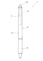
図1及び図9に本発明の実施の形態を示す。本実施の形態の熱変色性筆記具1は、軸筒2と、該軸筒2内に収容される筆記体9と、該筆記体9のペン先を軸筒2の前端孔31より出没自在にさせる出没機構とを備える。
1 and 9 show an embodiment of the present invention. The
・筆記体
前記筆記体9は、ペン先91と、該ペン先91が前端開口部に圧入固着されたインキ収容管と、該インキ収容管内に充填される熱変色性インキと、該熱変色性インキの後端に充填され且つ該熱変色性インキの消費に伴い前進する追従体(例えば高粘度流体)とからなる。
-Cursive body The
前記ペン先91は、例えば、前端に回転可能にボールを抱持した金属製のボールペンチップのみからなる構成、または前記ボールペンチップの後部外面を保持した合成樹脂製のペン先ホルダーからなる構成のいずれであってもよい。また、前記インキ収容管の後端開口部に、インキ収容管と外部とが通気可能な通気孔を備えた尾栓が取り付けられる。
The
・軸筒
前記軸筒2は、先細円筒状の前軸3と、該前軸3の後端部に連結される円筒状の中間軸4と、該中間軸4の後端部に連結される円筒状の後軸5とからなる。
Shaft cylinder The
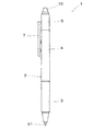
図5に前軸3を示す。前記前軸3は、合成樹脂の成形体からなる先細円筒状の本体3aと、該本体3a外面に設けられる弾性材料からなる把持部3bとからなる。前記把持部3bは、2色成形または装着により設けられる。前記前軸3の後端部は縮径され、その外面にはオネジ部32が形成される。前記前軸3の前端には、前端孔31が前後方向に貫設される。
FIG. 5 shows the
図6に中間軸4を示す。前記中間軸4は、円筒状の合成樹脂の成形体からなる。前記中間軸4の前端部内面には、メネジ部46が形成される。前記メネジ部46に前記前軸3のオネジ部32が螺合可能である。前記中間軸4の後端部には、縮径部43が一体に形成される。前記縮径部43には、前端が閉鎖され且つ後端が開放された、前後方向に延びる第1の長孔44が形成される。さらに、前記縮径部43の外面には外向突起45が一体に形成される。また、前記中間軸4の第1の長孔44よりも前方の内面には、カム部41が一体に形成される。また、前記中間軸4の外面には、係止突起47が一体に形成される。ペン先没入状態において、前記係止突起47とクリップ体7の玉部71aとの間でポケット等が挟持可能である。また、前記カム部41の後方且つ第1の長孔44の前方(即ちカム部41と第1の長孔44との間)の中間軸4の内面には、段部42が一体に形成される。
FIG. 6 shows the
図7に後軸5を示す。前記後軸5は、円筒状の合成樹脂の成形体からなる。前記後軸5の前端部側壁には、前端が開放され且つ後端が閉鎖された、前後方向に延びる第2の長孔51が形成される。また、前記後軸5の後端には、取付孔52が前後方向に貫設される。前記取付孔52に弾性材料からなる摩擦部10が圧入嵌合される。また、前記後軸5の内面には、内向突起53が一体に形成される。
FIG. 7 shows the
図8にクリップ体7を示す。前記クリップ体7は、前後方向に延びるクリップ本体71と、該クリップ本体71の後部に一体に連設される基部72と、該基部72と一体に連設され且つ基部72より前方に延びる筒状部73とからなる。前記クリップ体7は、合成樹脂の成形体により得られる。前記クリップ本体71は、裏面に玉部71aが突設される。前記筒状部73の前端には、カム歯73aが一体に形成される。
FIG. 8 shows the
・クリップ体の組立
前記クリップ体7の組立について説明する。前記中間軸4の第1の長孔44の後端開放部より、該第1の長孔44にクリップ体7の基部72を挿入するとともに、クリップ体7の筒状部73を中間軸4内に挿入する。その後、中間軸4の第1の長孔44と後軸5の第2の長孔51とを径方向に連通させるように(径方向に重なるように)、前記後軸5の内面を前記中間軸4の縮径部43の外面に嵌合させるとともに、クリップ体7の基部72を、第2の長孔51の前端開放部より、該第2の長孔51に挿入する。それにより、前記第1の長孔44と第2の長孔51とにより、前後方向に延びるスライド孔21が形成されるとともに、前記スライド孔21より径方向外方にクリップ体7(クリップ本体71及び基部72の一部)が突出され、前記クリップ体7がスライド孔に沿って前後方向にスライド可能(前後方向に摺動可能)に構成される。尚、このとき、前記中間軸4の縮径部43外面の外向突起45と後軸5の内面の内向突起53が係合される。
-Assembly of a clip body The assembly of the said
前記摩擦部10が固定された後軸5を中間軸4の後端部に連結することによって、前記摩擦部10が軸筒2の後端に固定される。また、前軸3と中間軸4とが螺合により着脱自在に連結され、それにより、筆記体9を交換可能にできる。
By connecting the
・出没機構
前記出没機構は、回転カム機構を用いたサイドスライド式出没機構である。前記出没機構は、中間軸4内面に形成されたカム部41に係合し且つ筆記体9の後端に当接する回転部材6と、該回転部材6に係合し且つスライド孔より径方向外方に突出するクリップ体7と、軸筒2内に収容され且つ筆記体9を後方に付勢する弾発体8(例えば圧縮コイルスプリング)とからなる。本実施の形態の出没機構は、ペン先突出操作及びペン先没入操作のいずれもがクリップ体7を前方にスライド操作するダブルノック式である。
-In / out mechanism The in / out mechanism is a side slide type in / out mechanism using a rotating cam mechanism. The retracting mechanism includes a rotating
前記カム部41は、前方に突出する鋸歯状の複数のカム歯41aと、該カム歯41a間に形成されるカム溝41bとを備える。前記回転部材6は、その外面に長手方向に延びる4本の突条61を備え、該突条61が、カム部41のカム歯41a及びカム部41のカム溝41bと係合される。前記クリップ体7の筒状部73の前端には、回転部材6の突条61の後端と係合するカム歯73aが形成される。
The
・ペン先の出没
ペン先没入状態からクリップ体7を前方に、弾発体8による後方付勢に抗してスライド操作すると、クリップ体7の筒状部73によって回転部材6が前方に押圧され、前記回転部材6の突条61がカム溝41bに沿って前方に移動するに伴って、前記回転部材6が筆記体9の後端を前方に押圧し、ペン先91が前端孔31より外部に突出される。このとき、前記筒状部73のカム歯73aと前記回転部材6の突条61との当接によって回転部材6がカム部41に対して一定角度だけ回転する。それにより、前記回転部材6の突条61がカム部41のカム歯41aに係合され、ペン先突出状態が維持される。
When the
ペン先突出状態からクリップ体7を前方にスライド操作すると、クリップ体7の筒状部73が回転部材6を前方に押圧し、前記筒状部73のカム歯73aと前記回転部材6の突条61との当接によって回転部材6がカム部41に対して一定角度だけ回転する。それによって、前記突条61とカム部41のカム歯41aとの係合状態が解除され、弾発体8による後方付勢により、前記突条61がカム部41のカム溝41bに沿って後方に移動する。前記回転部材6が後方に移動することに伴って、筆記体9が後方に移動し、ペン先没入状態となる。前記突条61はカム部41の後方の段部42に係止し、ペン先没入状態が維持される。
When the
・クリップ体の他の例
図9にクリップ体7の他の実施の形態を示す。本実施の形態の図8のクリップ体7と異なる点は、カム歯74aを有する円筒体74をクリップ体7の筒状部73に取り付けた点であり、他の構成及び作用効果は図1乃至図8の実施の形態と同様であるため、説明を省略する。
Another Example of Clip Body FIG. 9 shows another embodiment of the
・摩擦部
本実施の形態において、前記摩擦部10を構成する弾性材料は、弾性を有する合成樹脂(ゴム、エラストマー)が好ましく、例えば、シリコーン樹脂、SBS樹脂(スチレン−ブタジエン−スチレン共重合体)、SEBS樹脂(スチレン−エチレン−ブタジエン−スチレン共重合体)、フッ素系樹脂、クロロプレン樹脂、ニトリル樹脂、ポリエステル系樹脂、エチレンプロピレンジエンゴム(EPDM)等が挙げられる。前記摩擦部10を構成する弾性を有する合成樹脂は、高摩耗性の弾性材料(例えば、消しゴム等)からなるものよりも、摩擦時に摩耗カス(消しカス)が殆ど生じない低摩耗性の弾性材料からなることが好ましい。また、前記摩擦部10は、軸筒2の後端部外面に少なくとも設ければよく、例えば、軸筒2の後端部に弾性材料よりなる摩擦部10を圧入、係合、螺合、嵌合、接着、2色成形等によって固着する構成、または軸筒2の全体もしくは後軸5の全体が弾性材料
により一体に形成される構成が挙げられる。
-Friction part In this Embodiment, the elastic material which comprises the said
・熱変色性インキ
本実施の形態において、前記熱変色性インキは、可逆熱変色性インキが好ましい。前記可逆熱変色性インキは、発色状態から加熱により消色する加熱消色型、発色状態または消色状態を互変的に特定温度域で記憶保持する色彩記憶保持型、または、消色状態から加熱により発色し、発色状態からの冷却により消色状態に復する加熱発色型等、種々のタイプを単独または併用して構成することができる。
-Thermochromic ink In the present embodiment, the thermochromic ink is preferably a reversible thermochromic ink. The reversible thermochromic ink is a heat decoloring type that decolors by heating from a colored state, a color memory retaining type that reversibly stores and retains a colored state or a decolored state in a specific temperature range, or from a decolored state Various types such as a heating coloring type that develops color by heating and returns to a decolored state by cooling from the colored state can be used alone or in combination.
また、前記可逆熱変色性インキに含有される色材は、従来より公知の(イ)電子供与性呈色性有機化合物、(ロ)電子受容性化合物、及び(ハ)前記両者の呈色反応の生起温度を決める反応媒体、の必須三成分を少なくとも含む可逆熱変色性組成物をマイクロカプセル中に内包させた可逆熱変色性顔料が好適に用いられる。 The coloring material contained in the reversible thermochromic ink includes conventionally known (a) electron donating color-forming organic compounds, (b) electron-accepting compounds, and (c) color reactions of both. A reversible thermochromic pigment in which a reversible thermochromic composition containing at least the essential three components of a reaction medium for determining the occurrence temperature of the polymer is encapsulated in a microcapsule is preferably used.
本実施の形態では、図10に示すように、温度変化による着色濃度の変化をプロットした曲線の形状が、温度を変色温度域より低温側から上昇させていく場合と逆に変色温度域より高温側から下降させていく場合とで異なる経路を辿って変色し、完全発色温度(t1)以下の低温域での発色状態、または完全消色温度(t4)以上の高温域での消色状態が、特定温度域〔t2〜t3の間の温度域(実質的二相保持温度域)〕で記憶保持できる色彩記憶保持型熱変色性インキが適用されることが好ましい。図10において、ΔHは、ヒステリシスの程度を示す温度幅(即ちヒステリシス幅)を示す。ΔHの値が小さいと、変色前後の両状態のうち一方の状態しか存在しえない。ΔHの値が大きいと、変色前後の各状態の保持が容易となる。 In the present embodiment, as shown in FIG. 10, the shape of the curve plotting the change in color density due to the temperature change is higher than the color change temperature range, contrary to the case where the temperature is raised from the lower temperature side than the color change temperature range. The color changes by following a different route depending on whether the color is lowered from the side, and a color development state in a low temperature region below the complete color development temperature (t1) or a color erase state in a high temperature region above the complete color removal temperature (t4) It is preferable to apply a color memory retention type thermochromic ink that can be stored and retained in a specific temperature range [temperature range between t2 and t3 (substantially two-phase retention temperature range)]. In FIG. 10, ΔH represents a temperature width (ie, hysteresis width) indicating the degree of hysteresis. When the value of ΔH is small, only one of the two states before and after the color change can exist. When the value of ΔH is large, it is easy to maintain each state before and after the color change.
本実施の形態では、前記熱変色性インキの摩擦部10の摩擦熱による変色温度は、25℃〜95℃(好ましくは36℃〜95℃)に設定される。即ち、本実施の形態では、前記高温側変色点〔完全消色温度(t4)〕を、25℃〜95℃(好ましくは、36℃〜90℃)の範囲に設定し、前記低温側変色点〔完全発色温度(t1)〕を、−30℃〜+20℃(好ましくは、−30℃〜+10℃)の範囲に設定することが有効である。それにより、常態(日常の生活温度域)で呈する色彩の保持を有効に機能させることができるとともに、可逆熱変色性インキによる筆跡を摩擦部10による摩擦熱で容易に変色することができる。
In the present embodiment, the color change temperature due to frictional heat of the
本実施の形態の熱変色性筆記具1は、少なくとも摩擦操作時に、前記摩擦部10を軸筒2の後端に固定したことにより、摩擦操作時、摩擦部10の後方への移動が阻止されるため、摩擦部10を用いて安定した摩擦操作が可能となる。また、本実施の形態の熱変色性筆記具1は、ペン先91を出没する際、クリップ体7を操作し、摩擦部10を操作しないため、摩擦部10が手垢等で汚れることを回避できる。また、本実施の形態の熱変色性筆記具1は、軸筒2外面にクリップを設けたにもかかわらず、従来の多芯式の熱変色性筆記具に比べ、突出部分が少なく、外観デザイン上の自由度が増加し、スマートな外観を得ることができる。
In the
本実施の形態の熱変色性筆記具1は、出没機構が、回転カム機構を用いたサイドスライド式出没機構であり、ペン先突出操作及びペン先没入操作の何れもがクリップ体7を前方にスライド操作するタイプ(いわゆるダブルノック式の出没機構)であるため、操作方法が簡単であり、ユーザーが操作方法を容易に習得できる。
The
本実施の形態の熱変色性筆記具1は、後方に開放された第1の長孔44と前方に開放された第2の長孔51とによりスライド孔21を形成したことによって、クリップ体7をスライド孔21に容易に挿入することができる。
In the
本実施の形態の熱変色性筆記具1は、ペン先突出状態を解除しペン先没入状態にする際、弾発体8の後方付勢による筆記体9及びクリップ体7が後方移動し、クリップ体7と弾性材料よりなる摩擦部10とが当接する。それにより、その際に筆記体9に加わる衝撃が緩和される。その結果、筆記体9内のインキの逆流等やペン先91からの空気の混入を防止できる。
In the
1 熱変色性筆記具(筆記具)
2 軸筒
21 スライド孔
3 前軸
31 前端孔
32 オネジ部
3a 本体
3b 把持部
4 中間軸
41 カム部
41a カム歯
41b カム溝
42 段部
43 縮径部
44 第1の長孔
45 外向突起
46 メネジ部
47 係止突起
5 後軸
51 第2の長孔
52 取付孔
53 内向突起
6 回転部材
61 突条
7 クリップ体(操作体)
71 クリップ本体
71a 玉部
72 基部
73 筒状部
73a カム歯
74 円筒体
74a カム歯
8 弾発体
9 筆記体
91 ペン先
10 摩擦部
1 Thermochromic writing instrument (writing instrument)
2
71
Claims (4)
少なくとも一の前記操作体と、前記軸筒の側壁に設けた前後方向に延びるスライド孔と、前記スライド孔に配設した前記操作体を前方へスライド操作することで、前記筆記体のペン先を没入状態から突出状態にする出没機構とを備え、
前記軸筒が互いに連結可能な複数の部品からなり、前記軸筒を構成する二つの前記部品の各側壁に、前方又は後方が開放され且つ前後方向に延びる第1又は第2の長孔をそれぞれ設け、二つの前記部品を連結したときに、前記第1及び第2の長孔が、互いに連通して前記スライド孔を形成し、
前記出没機構として、円周方向に沿って交互に配置された前後方向に延びる複数のカム歯及びカム溝と、前記筆記体の後方に回転可能に配置され、前記カム歯又は前記カム溝に交互に係合可能な複数の突条を有する回転部材と、前記操作体に設けられ、前記回転部材を回動させる複数の他のカム歯と、前記筆記体を後方に付勢する弾発体と、を前記軸筒内に備え、
前記軸筒を構成する二つの前記部品のうち、前記筆記具の前側に位置する部品には、その側壁に前記第1の長孔を設けるとともに、前記側壁の内面に前記カム歯及び前記カム溝を設け、前記第1の長孔が、前記カム歯及び前記カム溝よりも後方に延びて、前記側壁の後端で開放されることを特徴とする筆記具。 A writing instrument configured to accommodate a writing body in a shaft tube, operate the operating body provided on the shaft tube to move the writing body in the front-rear direction, and to allow the pen tip of the writing body to protrude from the tip of the writing tool. There,
At least one of the operating body, a slide hole extending in the front-rear direction provided on a side wall of the shaft tube, and a sliding operation of the operating body disposed in the slide hole forward, the pen tip of the writing body With an in / out mechanism for changing from an immersive state to a protruding state,
The shaft cylinder is composed of a plurality of parts that can be connected to each other, and the first or second elongated hole that opens in the front or rear and extends in the front-rear direction is formed in each side wall of the two parts constituting the shaft cylinder, respectively. When the two parts are connected, the first and second elongated holes communicate with each other to form the slide hole ,
As the retracting mechanism, a plurality of cam teeth and cam grooves extending in the front-rear direction alternately arranged along the circumferential direction, and rotatably arranged behind the writing body, the cam teeth or the cam grooves are alternately arranged. A rotating member having a plurality of protrusions that can be engaged with each other, a plurality of other cam teeth that are provided on the operating body and rotate the rotating member, and a resilient body that urges the writing body backward. In the shaft tube,
Of the two parts constituting the shaft cylinder, the part located on the front side of the writing instrument is provided with the first elongated hole in the side wall, and the cam teeth and the cam groove are formed on the inner surface of the side wall. provided, the first long hole, said extending rearward from the cam teeth and the cam groove, and wherein the Rukoto is open at the rear end of the side wall writing instrument.
前記他の部品の側壁を、前記一の部品の側壁の後端外面に嵌合させたときに、前記第1及び第2の長孔が、互いに径方向に重なった状態で連通して前記スライド孔を形成する請求項1又は2記載の筆記具。 Of the two parts constituting the shaft cylinder, one part located on the front side of the writing instrument is provided with the first elongated hole opened at the rear end of the side wall, and on the rear side of the writing instrument. The other part located is provided with the second elongated hole opened at the front end of the side wall,
When the side wall of the other part is fitted to the outer surface of the rear end of the side wall of the one part, the first and second elongated holes communicate with each other in a state of overlapping each other in the radial direction. The writing instrument according to claim 1 or 2, wherein a hole is formed .
Priority Applications (38)
| Application Number | Priority Date | Filing Date | Title |
|---|---|---|---|
| JP2010145648A JP5698927B2 (en) | 2010-06-25 | 2010-06-25 | Writing instrument |
| EP17155130.2A EP3184320B1 (en) | 2010-02-03 | 2011-01-31 | Writing instrument |
| ES11739705T ES2862911T3 (en) | 2010-02-03 | 2011-01-31 | Writing tool |
| SG10201900934WA SG10201900934WA (en) | 2010-02-03 | 2011-01-31 | Writing instrument |
| SG10201503145QA SG10201503145QA (en) | 2010-02-03 | 2011-01-31 | Writing instrument |
| PCT/JP2011/051905 WO2011096357A1 (en) | 2010-02-03 | 2011-01-31 | Writing tool |
| US13/576,826 US9108456B2 (en) | 2010-02-03 | 2011-01-31 | Writing instrument |
| CN201180008420.9A CN102741061B (en) | 2010-02-03 | 2011-01-31 | Pen |
| CN201510587925.5A CN105128559A (en) | 2010-02-03 | 2011-01-31 | Pen |
| CN201410392571.4A CN104191862B (en) | 2010-02-03 | 2011-01-31 | Pen |
| KR1020127020210A KR101779233B1 (en) | 2010-02-03 | 2011-01-31 | Writing tool |
| PL17155130T PL3184320T3 (en) | 2010-02-03 | 2011-01-31 | Writing instrument |
| ES17155130T ES2825824T3 (en) | 2010-02-03 | 2011-01-31 | Writing instrument |
| TW100103655A TWI522248B (en) | 2010-02-03 | 2011-01-31 | Hot discoloration writing pen and writing pen |
| KR1020197021099A KR102098571B1 (en) | 2010-02-03 | 2011-01-31 | Writing tool |
| KR1020207007322A KR102234299B1 (en) | 2010-02-03 | 2011-01-31 | Writing tool |
| KR1020217008884A KR102319864B1 (en) | 2010-02-03 | 2011-01-31 | Writing tool |
| KR1020177025257A KR101898408B1 (en) | 2010-02-03 | 2011-01-31 | Writing tool |
| SG2012056974A SG182835A1 (en) | 2010-02-03 | 2011-01-31 | Writing tool |
| ES13183586.0T ES2587078T3 (en) | 2010-02-03 | 2011-01-31 | Writing instrument |
| EP11739705.9A EP2532531B1 (en) | 2010-02-03 | 2011-01-31 | Writing tool |
| PL11739705T PL2532531T3 (en) | 2010-02-03 | 2011-01-31 | Writing tool |
| KR1020187025804A KR102004110B1 (en) | 2010-02-03 | 2011-01-31 | Writing tool |
| TW104115853A TWI614148B (en) | 2010-02-03 | 2011-01-31 | Thermochromic writing pen and writing instrument |
| CA2788724A CA2788724C (en) | 2010-02-03 | 2011-01-31 | Writing instrument |
| EP13183588.6A EP2676804B1 (en) | 2010-02-03 | 2011-01-31 | Thermochromic writing instrument |
| EP13183586.0A EP2676805B1 (en) | 2010-02-03 | 2011-01-31 | Writing tool |
| PL13183586.0T PL2676805T3 (en) | 2010-02-03 | 2011-01-31 | Writing tool |
| CN201510013376.0A CN104691157B (en) | 2010-02-03 | 2011-01-31 | Pen |
| HK15109193.9A HK1208410A1 (en) | 2010-02-03 | 2013-04-10 | Writing tool |
| HK15103454.6A HK1203459A1 (en) | 2010-02-03 | 2013-04-10 | Writing tool |
| HK16104618.6A HK1216733A1 (en) | 2010-02-03 | 2013-04-10 | Writing tool |
| HK13104326.2A HK1176912A1 (en) | 2010-02-03 | 2013-04-10 | Writing tool |
| HK14104024.6A HK1190674A1 (en) | 2010-02-03 | 2014-04-28 | Writing tool |
| US14/794,929 US9844973B2 (en) | 2010-02-03 | 2015-07-09 | Writing instrument |
| US15/830,456 US10493791B2 (en) | 2010-02-03 | 2017-12-04 | Writing instrument |
| US16/658,433 US11179963B2 (en) | 2010-02-03 | 2019-10-21 | Writing instrument |
| US17/532,043 US11738589B2 (en) | 2010-02-03 | 2021-11-22 | Writing instrument |
Applications Claiming Priority (1)
| Application Number | Priority Date | Filing Date | Title |
|---|---|---|---|
| JP2010145648A JP5698927B2 (en) | 2010-06-25 | 2010-06-25 | Writing instrument |
Related Parent Applications (1)
| Application Number | Title | Priority Date | Filing Date |
|---|---|---|---|
| JP2010022530 Division | 2010-02-03 | 2010-02-03 |
Publications (3)
| Publication Number | Publication Date |
|---|---|
| JP2011156853A JP2011156853A (en) | 2011-08-18 |
| JP2011156853A5 JP2011156853A5 (en) | 2013-04-04 |
| JP5698927B2 true JP5698927B2 (en) | 2015-04-08 |
Family
ID=44589235
Family Applications (1)
| Application Number | Title | Priority Date | Filing Date |
|---|---|---|---|
| JP2010145648A Active JP5698927B2 (en) | 2010-02-03 | 2010-06-25 | Writing instrument |
Country Status (1)
| Country | Link |
|---|---|
| JP (1) | JP5698927B2 (en) |
Families Citing this family (3)
| Publication number | Priority date | Publication date | Assignee | Title |
|---|---|---|---|---|
| JP5603737B2 (en) * | 2010-10-28 | 2014-10-08 | パイロットインキ株式会社 | Thermochromic writing instrument |
| WO2020149201A1 (en) * | 2019-01-18 | 2020-07-23 | 株式会社パイロットコーポレーション | Retractable writing instrument |
| KR102041880B1 (en) * | 2019-03-07 | 2019-11-07 | 임승재 | Writing instrument having a replaceable character figure that can rise and fall |
Family Cites Families (2)
| Publication number | Priority date | Publication date | Assignee | Title |
|---|---|---|---|---|
| JPS57179986U (en) * | 1981-05-13 | 1982-11-15 | ||
| JPH0628312Y2 (en) * | 1989-12-11 | 1994-08-03 | 株式会社パイロット | Writing instrument |
-
2010
- 2010-06-25 JP JP2010145648A patent/JP5698927B2/en active Active
Also Published As
| Publication number | Publication date |
|---|---|
| JP2011156853A (en) | 2011-08-18 |
Similar Documents
| Publication | Publication Date | Title |
|---|---|---|
| JP6756877B2 (en) | Thermal discoloration writing instrument | |
| WO2011096357A1 (en) | Writing tool | |
| JP5328554B2 (en) | Thermochromic writing instrument | |
| JP2011037086A (en) | Thermochromic writing utensil | |
| JP5653828B2 (en) | Thermochromic writing instrument | |
| JP6192964B2 (en) | Thermochromic writing instrument | |
| JP2010260218A (en) | Multi-core type thermochromic writing utensil | |
| JP5784967B2 (en) | Thermochromic writing instrument | |
| JP5681857B2 (en) | Thermochromic writing instrument | |
| JP5675015B2 (en) | Thermochromic writing instrument | |
| JP5358398B2 (en) | Thermochromic writing instrument | |
| JP5457263B2 (en) | Thermochromic writing instrument | |
| JP5698927B2 (en) | Writing instrument | |
| JP5358471B2 (en) | Thermochromic writing instrument | |
| JP5603738B2 (en) | Thermochromic writing instrument | |
| JP5694836B2 (en) | Thermochromic writing instrument | |
| JP5813929B2 (en) | Writing instrument | |
| JP5985584B2 (en) | Thermochromic writing instrument | |
| JP6081438B2 (en) | Thermochromic writing instrument | |
| JP5791946B2 (en) | Thermochromic writing instrument | |
| JP6184767B2 (en) | Thermochromic writing instrument | |
| JP5603737B2 (en) | Thermochromic writing instrument | |
| JP5551463B2 (en) | Thermochromic writing instrument | |
| JP3175844U (en) | Multi-core thermochromic writing instrument | |
| JP2010260219A (en) | Multi-core type thermochromic writing utensil |
Legal Events
| Date | Code | Title | Description |
|---|---|---|---|
| A621 | Written request for application examination |
Free format text: JAPANESE INTERMEDIATE CODE: A621 Effective date: 20130201 |
|
| A521 | Written amendment |
Free format text: JAPANESE INTERMEDIATE CODE: A523 Effective date: 20130219 |
|
| A131 | Notification of reasons for refusal |
Free format text: JAPANESE INTERMEDIATE CODE: A131 Effective date: 20140430 |
|
| A521 | Written amendment |
Free format text: JAPANESE INTERMEDIATE CODE: A523 Effective date: 20140630 |
|
| A711 | Notification of change in applicant |
Free format text: JAPANESE INTERMEDIATE CODE: A711 Effective date: 20140909 |
|
| RD03 | Notification of appointment of power of attorney |
Free format text: JAPANESE INTERMEDIATE CODE: A7423 Effective date: 20141010 |
|
| TRDD | Decision of grant or rejection written | ||
| A01 | Written decision to grant a patent or to grant a registration (utility model) |
Free format text: JAPANESE INTERMEDIATE CODE: A01 Effective date: 20150127 |
|
| A61 | First payment of annual fees (during grant procedure) |
Free format text: JAPANESE INTERMEDIATE CODE: A61 Effective date: 20150216 |
|
| R150 | Certificate of patent or registration of utility model |
Ref document number: 5698927 Country of ref document: JP Free format text: JAPANESE INTERMEDIATE CODE: R150 |