JP5985584B2 - Thermochromic writing instrument - Google Patents

Thermochromic writing instrument Download PDF

Info

Publication number
JP5985584B2
JP5985584B2 JP2014234367A JP2014234367A JP5985584B2 JP 5985584 B2 JP5985584 B2 JP 5985584B2 JP 2014234367 A JP2014234367 A JP 2014234367A JP 2014234367 A JP2014234367 A JP 2014234367A JP 5985584 B2 JP5985584 B2 JP 5985584B2
Authority
JP
Japan
Prior art keywords
friction
rear end
shaft cylinder
thermochromic
writing instrument
Prior art date
Legal status (The legal status is an assumption and is not a legal conclusion. Google has not performed a legal analysis and makes no representation as to the accuracy of the status listed.)
Active
Application number
JP2014234367A
Other languages
Japanese (ja)
Other versions
JP2015057329A (en
Inventor
邦彦 岡田
邦彦 岡田
Current Assignee (The listed assignees may be inaccurate. Google has not performed a legal analysis and makes no representation or warranty as to the accuracy of the list.)
Pilot Ink Co Ltd
Pilot Corp KK
Original Assignee
Pilot Ink Co Ltd
Pilot Corp KK
Priority date (The priority date is an assumption and is not a legal conclusion. Google has not performed a legal analysis and makes no representation as to the accuracy of the date listed.)
Filing date
Publication date
Application filed by Pilot Ink Co Ltd, Pilot Corp KK filed Critical Pilot Ink Co Ltd
Priority to JP2014234367A priority Critical patent/JP5985584B2/en
Publication of JP2015057329A publication Critical patent/JP2015057329A/en
Application granted granted Critical
Publication of JP5985584B2 publication Critical patent/JP5985584B2/en
Active legal-status Critical Current
Anticipated expiration legal-status Critical

Links

Images

Description

本発明は、熱変色性筆記具に関する。 The present invention relates to a thermochromic writing instrument.

特許文献1には、軸筒内に筆記体を前後方向に移動可能に収容し、軸筒の外面に操作部を設け、前記操作部を操作することにより前記筆記体のペン先を軸筒の前端孔から出没可能に構成し、前記筆記体の内部に熱変色性インキを収容し、前記筆記体の前端に前記熱変色性インキが吐出可能なペン先を設け、前記軸筒の外面に、前記熱変色性インキの筆跡を摩擦しその際に生じる摩擦熱で該筆跡を熱変色可能な摩擦部を設けた熱変色性筆記具が開示されている。 In Patent Document 1, a writing body is accommodated in a shaft cylinder so as to be movable in the front-rear direction, an operation portion is provided on an outer surface of the shaft tube, and the pen tip of the writing body is attached to the shaft tube by operating the operation portion. It is configured to be able to appear and retract from a front end hole, accommodates thermochromic ink inside the cursive body, provides a pen tip capable of ejecting the thermochromic ink at the front end of the cursive body, on the outer surface of the shaft cylinder, There has been disclosed a thermochromic writing instrument provided with a friction portion capable of thermally changing the handwriting with frictional heat generated by rubbing the handwriting of the thermochromic ink.

前記特許文献1は、軸筒後端の操作部(本願のノック体に相当)を前方に押圧するタイプにおいて操作部に摩擦部を設けた場合、該摩擦部を用いて摩擦操作すると、被筆記面によって操作部が前方に移動し、安定した摩擦操作を行うことができないおそれがある。特に、ペン先突出操作及びペン先没入操作のいずれもが操作部を前方に押圧操作するタイプの出没機構(いわゆるダブルノック式)を採用し且つ操作部に摩擦部を設けた場合、ペン先突出状態において操作体が前後方向にがたつき、安定した摩擦操作を行うことができないおそれがある。 In Patent Document 1, when a friction part is provided in the operation part in a type in which the operation part (corresponding to the knock body of the present application) at the rear end of the shaft cylinder is pressed forward, a friction operation is performed using the friction part. There is a possibility that the operation part moves forward by the surface and a stable friction operation cannot be performed. In particular, when both a pen tip protruding operation and a pen tip immersing operation employ a retracting mechanism (so-called double knock type) that pushes the operating portion forward and a friction portion is provided in the operating portion, the pen tip protrudes. In this state, the operating body may rattle in the front-rear direction, and a stable friction operation may not be performed.

国際公開第2008/105227号パンフレットInternational Publication No. 2008/105227 Pamphlet

本発明は、前記従来の問題点を解決するものであって、ノック体後端の摩擦部を用いて安定した摩擦操作が可能となる熱変色性筆記具を提供しようとするものである。尚、本発明で、「前」とは、ペン先側を指し、「後」とは、その反対側を指す。尚、本発明で、「ペン先没入状態」とは、ペン先が軸筒内に没入した状態をいい、「ペン先突出状態」とは、ペン先が軸筒の前端より外部に突出した状態をいう。 The present invention is intended to solve the above-described conventional problems, and to provide a thermochromic writing instrument that enables a stable friction operation using a friction portion at the rear end of the knock body. In the present invention, “front” refers to the pen tip side, and “rear” refers to the opposite side. In the present invention, the “pen nib immersive state” refers to a state in which the pen nib is immersed in the shaft cylinder, and the “pen nib protruding state” refers to a state in which the pen nib projects outward from the front end of the shaft cylinder. Say.

本願の第1の発明は、筆記体3の内部に熱変色性インキを収容し、前記筆記体3の前端に前記熱変色性インキが吐出可能なペン先31を設け、前記筆記体3を軸筒2内に前後方向に移動可能に収容し、前記軸筒2の後端部にノック体6を設け、前記ノック体6を前方に押圧することにより前記ペン先31を前記軸筒2の前端孔21から突出状態にし、再度、前記ノック体6を前方に押圧することにより前記ペン先突出状態を解除し前記ペン先31を前記軸筒2の前端孔21より前記軸筒2内に没入状態にする出没機構を備え、前記ノック体6の後端部外面に、前記熱変色性インキの筆跡を摩擦しその際に生じる摩擦熱で前記熱変色性インキの筆跡を熱変色可能な摩擦部64を設けた熱変色性筆記具であって、
前記軸筒2の後端開口部内面と前記ノック体6の外面との間に前後方向に移動可能且つ回転可能に筒状の締め付け部材8を設け、前記摩擦部64を用いて摩擦操作する際、前記締め付け部材8を回転操作することにより、前記締め付け部材8が、前記ノック体6の外面または前記摩擦部64の外面に圧接され、前記軸筒2に対する前記摩擦部64の前後方向の移動を阻止してなることを要件とする。
1st invention of this application stores the thermochromic ink in the inside of the writing body 3, the pen tip 31 which can discharge the said thermochromic ink is provided in the front end of the said writing body 3, and the said writing body 3 is made into a shaft. The cylinder 2 is accommodated so as to be movable in the front-rear direction, a knock body 6 is provided at the rear end portion of the shaft cylinder 2, and the pen tip 31 is pushed forward by pushing the knock body 6 forward. The pen tip protruding state is released by pressing the knock body 6 forward again, and the pen tip 31 is immersed in the shaft tube 2 from the front end hole 21 of the shaft tube 2. A friction portion 64 that rubs the handwriting of the thermochromic ink on the outer surface of the rear end portion of the knock body 6 and can thermally discolor the handwriting of the thermochromic ink by frictional heat generated at that time. A thermochromic writing instrument provided with
A movable and rotatable tubular clamping member 8 in the longitudinal direction between the outer surface of the rear end opening inner surface and the pushing member 6 of the barrel 2 is provided, when the friction operation using the friction portion 64 By rotating the fastening member 8, the fastening member 8 is pressed against the outer surface of the knock body 6 or the outer surface of the friction part 64, and the friction part 64 moves in the front-rear direction with respect to the shaft cylinder 2. It is a requirement to stop.

前記第1の発明の熱変色性筆記具1は、前記摩擦部64を用いて摩擦操作する際、前記締め付け部材8を回転操作することにより、前記締め付け部材8が、前記ノック体6の外面または前記摩擦部64の外面に圧接され、前記軸筒2に対する前記摩擦部64の前後方向の移動を阻止してなることにより、ノック体6の後端部外面の摩擦部64を用いて安定した摩擦操作が可能となる。特に、前記第1の発明の熱変色性筆記具1は、ノック体6及び摩擦部64と別部材の締め付け部材8を用いることにより、摩擦部64の前後方向の移動を確実に阻止できるとともに、ノック体6または摩擦部64を特殊な形状にする必要がなく、ノック体6または摩擦部64の外観を自由に設定できる。 In the thermochromic writing instrument 1 of the first invention, when the frictional operation is performed using the frictional portion 64, the tightening member 8 is rotated to operate the tightening member 8 so that the outer surface of the knock body 6 or the Stable friction operation using the friction part 64 on the outer surface of the rear end of the knock body 6 by being pressed against the outer surface of the friction part 64 and preventing the friction part 64 from moving in the front-rear direction with respect to the shaft cylinder 2. Is possible. In particular, the thermochromic writing instrument 1 according to the first aspect of the invention can reliably prevent the frictional portion 64 from moving in the front-rear direction by using the knocking member 6 and the frictional portion 64 and the fastening member 8 which is a separate member. It is not necessary to make the body 6 or the friction part 64 into a special shape, and the appearance of the knock body 6 or the friction part 64 can be freely set.

前記第2の発明は、前記第1の発明の熱変色性筆記具1において、前記摩擦部64を弾性材料により構成されることを要件とする。 The second invention is the thermochromic writing instrument 1 of the first aspect of the present invention may be a requirement that is configured the friction portion 64 of an elastic material.

前記第2の発明の熱変色性筆記具1は、摩擦部64を用いて摩擦操作する際、軸筒2に対する摩擦部64の前後方向の移動を一層確実に阻止できる。 The thermochromic writing instrument 1 according to the second aspect of the present invention can more reliably prevent the frictional portion 64 from moving in the front-rear direction relative to the shaft tube 2 when the frictional operation is performed using the frictional portion 64.

本願の第3の発明は、前記第1または第2の発明の熱変色性筆記具1において、前記締め付け部材8が、前記軸筒2の後端開口部内面との圧接により径方向内方に弾性変形し且つ前記ノック体6の外面に圧接可能な変形部81と、該変形部81の後方に形成され且つ前記軸筒2の後端開口部内面のメネジ部22に螺合可能なオネジ部82と、該オネジ部82より後方に形成される回転操作部83とからなることを要件とする。 According to a third invention of the present application, in the thermochromic writing instrument 1 of the first or second invention, the fastening member 8 is elastically inward in the radial direction by pressure contact with the inner surface of the rear end opening of the shaft tube 2. A deformable portion 81 that can be deformed and press-contacted to the outer surface of the knock body 6, and a male screw portion 82 that is formed behind the deformable portion 81 and can be screwed into the internal thread portion 22 on the inner surface of the rear end opening of the shaft cylinder 2. And a rotation operation portion 83 formed behind the male screw portion 82.

前記第3の発明の熱変色性筆記具1は、回転操作部83を回転操作することにより、締め付け部材8によるノック体6または摩擦部64の締め付け及び締め付け解除を容易に行うことができる。 The thermochromic writing instrument 1 according to the third aspect of the present invention can easily tighten and release the knock body 6 or the friction portion 64 by the tightening member 8 by rotating the rotation operation portion 83.

前記第3の発明の熱変色性筆記具1は、摩擦操作する際、回転操作部83をネジ締め方向に回転させることにより、締め付け部材8が軸筒2に対して前方に移動し、変形部81と軸筒2の後端開口部内面とが圧接する。それにより、変形部81が径方向内方に弾性変形するとともに変形部81がノック体6の外面または摩擦部64の外面に圧接され、締め付け部材8によるノック体6または摩擦部64の容易な締め付け(即ち前後方向の移動阻止)が可能となる。そして、前記第3の発明の熱変色性筆記具1は、ノック体6を操作する際、回転操作部83をネジ緩み方向に回転させることにより、締め付け部材8が軸筒2に対して後方に移動し、変形部81と軸筒2の後端開口部内面との圧接が解除されるとともに変形部81が径方向外方に弾性変形し、それにより、変形部81によるノック体6または摩擦部64との締め付けが容易に解除できる。 In the thermochromic writing instrument 1 according to the third aspect of the present invention, when the friction operation is performed, the rotation member 83 is rotated in the screw tightening direction, whereby the tightening member 8 is moved forward with respect to the shaft tube 2, and the deformable portion 81. And the inner surface of the rear end opening of the shaft cylinder 2 are in pressure contact with each other. As a result, the deformable portion 81 is elastically deformed radially inward, and the deformable portion 81 is pressed against the outer surface of the knock body 6 or the outer surface of the friction portion 64, so that the knock body 6 or the friction portion 64 can be easily tightened by the tightening member 8. (That is, the movement in the front-rear direction can be prevented). In the thermochromic writing instrument 1 of the third aspect of the invention, when the knock body 6 is operated, the fastening member 8 is moved backward with respect to the shaft tube 2 by rotating the rotation operation portion 83 in the screw loosening direction. Then, the pressure contact between the deformable portion 81 and the inner surface of the rear end opening of the shaft cylinder 2 is released, and the deformable portion 81 is elastically deformed radially outward, whereby the knock body 6 or the friction portion 64 by the deformable portion 81 is obtained. Can be easily released.

・摩擦部
本発明において摩擦部64は、弾性材料(軟質材料)から構成されることが好ましい。前記摩擦部64を構成する弾性材料は、弾性を有する合成樹脂(ゴム、エラストマー)が好ましく、例えば、シリコーン樹脂、SBS樹脂(スチレン−ブタジエン−スチレン共重合体)、SEBS樹脂(スチレン−エチレン−ブチレン−スチレン共重合体)、フッ素系樹脂、クロロプレン樹脂、ニトリル樹脂、ポリエステル系樹脂、エチレンプロピレンジエンゴム(EPDM)等が挙げられる。前記摩擦部64を構成する弾性を有する合成樹脂は、高摩耗性の弾性材料(例えば、消しゴム等)からなるものよりも、摩擦時に摩耗カス(消しカス)が殆ど生じない低摩耗性の弾性材料からなることが好ましい。尚、本発明のノック体6は、少なくとも後端部外面が弾性材料からなる構成であればよく、例えば、ノック体6全体を弾性材料から構成してもよい。
-Friction part In this invention, it is preferable that the friction part 64 is comprised from an elastic material (soft material). The elastic material constituting the friction part 64 is preferably a synthetic resin (rubber or elastomer) having elasticity. For example, silicone resin, SBS resin (styrene-butadiene-styrene copolymer), SEBS resin (styrene-ethylene-butylene). -Styrene copolymer), fluorine resin, chloroprene resin, nitrile resin, polyester resin, ethylene propylene diene rubber (EPDM) and the like. The synthetic resin having elasticity constituting the friction part 64 is a low wear elastic material that hardly generates wear debris (rubbing debris) at the time of friction, rather than a high wear elastic material (for example, an eraser). Preferably it consists of. In addition, the knock body 6 of the present invention only needs to have a configuration in which at least the outer surface of the rear end portion is made of an elastic material. For example, the entire knock body 6 may be made of an elastic material.

・熱変色性インキ
本願発明において、前記熱変色性インキは、可逆熱変色性インキが好ましい。前記可逆熱変色性インキは、発色状態から加熱により消色する加熱消色型、発色状態または消色状態を互変的に特定温度域で記憶保持する色彩記憶保持型、または、消色状態から加熱により発色し、発色状態からの冷却により消色状態に復する加熱発色型等、種々のタイプを単独または併用して構成することができる。
-Thermochromic ink In the present invention, the thermochromic ink is preferably a reversible thermochromic ink. The reversible thermochromic ink is a heat decoloring type that decolors by heating from a colored state, a color memory retaining type that reversibly stores and retains a colored state or a decolored state in a specific temperature range, or from a decolored state Various types such as a heating coloring type that develops color by heating and returns to a decolored state by cooling from the colored state can be used alone or in combination.

また、前記可逆熱変色性インキに含有される色材は、従来より公知の(イ)電子供与性呈色性有機化合物、(ロ)電子受容性化合物、及び(ハ)前記両者の呈色反応の生起温度を決める反応媒体、の必須三成分を少なくとも含む可逆熱変色性組成物をマイクロカプセル中に内包させた可逆熱変色性顔料が好適に用いられる。 The coloring material contained in the reversible thermochromic ink includes conventionally known (a) electron donating color-forming organic compounds, (b) electron-accepting compounds, and (c) color reactions of both. A reversible thermochromic pigment in which a reversible thermochromic composition containing at least the essential three components of a reaction medium for determining the occurrence temperature of the polymer is encapsulated in a microcapsule is preferably used.

本発明では、図5に示すように、温度変化による着色濃度の変化をプロットした曲線の形状が、温度を変色温度域より低温側から上昇させていく場合と逆に変色温度域より高温側から下降させていく場合とで異なる経路を辿って変色し、完全発色温度(t)以下の低温域での発色状態、または完全消色温度(t)以上の高温域での消色状態が、特定温度域〔t〜tの間の温度域(実質的二相保持温度域)〕で記憶保持できる色彩記憶保持型熱変色性インキが適用されることが好ましい。図5において、ΔHは、ヒステリシスの程度を示す温度幅(即ちヒステリシス幅)を示す。ΔHの値が小さいと、変色前後の両状態のうち一方の状態しか存在しえない。ΔHの値が大きいと、変色前後の各状態の保持が容易となる。 In the present invention, as shown in FIG. 5, the shape of the curve plotting the change in the color density due to the temperature change is contrary to the case where the temperature is raised from the lower temperature side than the color change temperature range, and from the higher temperature side than the color change temperature range. The color changes by following a different path depending on the descending state, and the color development state in the low temperature range below the complete color development temperature (t 1 ) or the color erase state in the high temperature range above the complete color erase temperature (t 4 ) It is preferable to apply a color memory retention type thermochromic ink that can be stored and retained in a specific temperature range [temperature range between t 2 and t 3 (substantially two-phase retention temperature range)]. In FIG. 5, ΔH indicates a temperature width (ie, hysteresis width) indicating the degree of hysteresis. When the value of ΔH is small, only one of the two states before and after the color change can exist. When the value of ΔH is large, it is easy to maintain each state before and after the color change.

本発明では、前記熱変色性インキの摩擦部64の摩擦熱による変色温度は、25℃〜95℃(好ましくは36℃〜95℃)に設定される。即ち、本発明では、前記高温側変色点〔完全消色温度(t)〕を、25℃〜95℃(好ましくは、36℃〜90℃)の範囲に設定し、前記低温側変色点〔完全発色温度(t)〕を、−30℃〜+20℃(好ましくは、−30℃〜+10℃)の範囲に設定することが有効である。それにより、常態(日常の生活温度域)で呈する色彩の保持を有効に機能させることができるとともに、可逆熱変色性インキによる筆跡を摩擦部64による摩擦熱で容易に変色することができる。 In the present invention, the color change temperature due to frictional heat of the frictional portion 64 of the thermochromic ink is set to 25 ° C. to 95 ° C. (preferably 36 ° C. to 95 ° C.). That is, in the present invention, the high temperature side discoloration point [complete decoloring temperature (t 4 )] is set in a range of 25 ° C. to 95 ° C. (preferably 36 ° C. to 90 ° C.), and the low temperature side discoloration point [ It is effective to set the complete color development temperature (t 1 )] in the range of −30 ° C. to + 20 ° C. (preferably −30 ° C. to + 10 ° C.). Accordingly, it is possible to effectively maintain the color exhibited in the normal state (daily life temperature range), and the handwriting by the reversible thermochromic ink can be easily discolored by the frictional heat generated by the friction portion 64.

本発明は、ノック体の後端部外面の摩擦部を用いて安定した摩擦操作が可能となる。 According to the present invention, a stable friction operation can be performed by using the friction portion on the outer surface of the rear end portion of the knock body.

本発明の実施の形態の締め付け部材による締め付け前の状態を示す縦断面図である。It is a longitudinal cross-sectional view which shows the state before the clamping | tightening by the clamping member of embodiment of this invention. 図1の締め付け部材による締め付け後の状態を示す縦断面図である。It is a longitudinal cross-sectional view which shows the state after the clamping | tightening by the clamping member of FIG. 図1の締め付け部材の斜視図である。It is a perspective view of the fastening member of FIG. 図1の出没機構を示す分解図である。It is an exploded view which shows the intrusion mechanism of FIG. 熱変色性インキの変色挙動を示す説明図である。It is explanatory drawing which shows the color change behavior of a thermochromic ink.

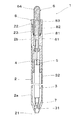
本発明の実施の形態を図1乃至図4に示す。
本実施の形態の熱変色性筆記具1は、軸筒2と、該軸筒2内に収容される筆記体3と、該筆記体3のペン先31を軸筒2の前端孔21より出没自在にさせる出没機構と、前記軸筒2の後端開口部に螺着される締め付け部材8とを備える。
An embodiment of the present invention is shown in FIGS.
The thermochromic writing instrument 1 of the present embodiment includes a shaft tube 2, a writing body 3 accommodated in the shaft tube 2, and a pen tip 31 of the writing body 3 that can be projected and retracted from a front end hole 21 of the shaft tube 2. And a retracting mechanism that is to be turned on and a fastening member 8 that is screwed into the rear end opening of the shaft tube 2.

前記軸筒2は、円筒状の前軸2aと、該前軸2aの後端に連結される円筒状の後軸2bとからなる。前記前軸2aと前記後軸2bは、螺合または嵌合により着脱自在に連結される。前記軸筒2の後端開口部(即ち後軸2bの後端開口部)内面にはメネジ部22が形成される。さらに、前記メネジ部22より前方の前記軸筒2の後端開口部(即ち後軸2bの後端開口部)内面には、前方に向かうに従い内径が小さくなる傾斜面23が形成される。
The shaft cylinder 2 includes a cylindrical front shaft 2a and a cylindrical rear shaft 2b connected to the rear end of the front shaft 2a. The front shaft 2a and the rear shaft 2b are detachably connected by screwing or fitting. A female thread portion 22 is formed on the inner surface of the rear end opening of the shaft cylinder 2 (that is, the rear end opening of the rear shaft 2b). Further, the inner surface (rear end opening of the words rear axle 2b) the rear end opening of the from the internal thread portion 22 forward of the barrel 2, the inclined surface 23 of the inner diameter in accordance buy toward the front is smaller is formed.

前記筆記体3は、ペン先31と、該ペン先31が前端開口部に圧入固着されたインキ収容管32と、該インキ収容管32内に充填される熱変色性インキと、該熱変色性インキの後端に充填され且つ該熱変色性インキの消費に伴い前進する追従体(例えば高粘度流体)とからなる。 The cursive body 3 includes a pen tip 31, an ink storage tube 32 in which the pen tip 31 is press-fitted and fixed to a front end opening, a thermochromic ink filled in the ink storage tube 32, and the thermochromic property. It consists of a follower (for example, a high-viscosity fluid) that fills the trailing edge of the ink and moves forward as the thermochromic ink is consumed.

前記ペン先31は、例えば、前端に回転可能にボールを抱持した金属製のボールペンのみからなる構成、または前記ボールペンチップの後部外面を保持した合成樹脂製のペン先ホルダーからなる構成のいずれであってもよい。また、前記インキ収容管32の後端開口部に、インキ収容管32内部と外部とが通気可能な通気孔を備えた尾栓を取り付けてもよい。 For example, the pen tip 31 is composed of only a metal ball pen having a ball rotatably held at the front end, or a synthetic resin pen tip holder holding the rear outer surface of the ball pen tip. There may be. Further, a tail plug provided with a vent hole through which the inside and the outside of the ink containing tube 32 can vent may be attached to the rear end opening of the ink containing tube 32.

前記出没機構は、回転カム機構を用いたノック式出没機構であり、軸筒2内面(後軸2b内面)に形成されたカム部4と係合し且つ筆記体3の後端と当接する回転部材5と、該回転部材5と係合し且つ軸筒2後端(後軸2b後端)より突出するノック体6と、軸筒2内に収容され且つ筆記体3を後方に付勢する弾発体7(例えば圧縮コイルスプリング)とからなる。本実施の形態の出没機構は、ペン先突出操作及びペン先没入操作のいずれもがノック体6を前方に押圧する操作のダブルノック式である。 The retracting mechanism is a knock-type retracting mechanism that uses a rotating cam mechanism, and engages with the cam portion 4 formed on the inner surface of the shaft cylinder 2 (the inner surface of the rear shaft 2b) and rotates in contact with the rear end of the writing body 3. A member 5, a knock body 6 that engages with the rotating member 5 and protrudes from the rear end (rear end of the rear shaft 2 b) of the shaft cylinder 2, and is accommodated in the shaft cylinder 2 and biases the writing body 3 backward. It consists of the bullet body 7 (for example, compression coil spring). The retracting mechanism of the present embodiment is a double knock type in which both the pen tip protruding operation and the pen tip retracting operation press the knock body 6 forward.

前記軸筒2内面のカム部4は、前方に突出する鋸歯状の複数のカム歯41と、該カム歯41間に形成され、回転部材5が係合するカム溝42とを備える[図4(c)参照]。前記回転部材5は、その外面に長手方向に延びる3本の突条51を備え、該突条51が、前記軸筒2内面のカム部4のカム溝42と係合される[図4(b)参照]。前記ノック体6は、棒状の本体部61と、その前端部に、カム部4のカム溝42内を摺動するガイド突条62と、回転部材5の突条51の後端と係合するカム歯63と、その後端部に摩擦部64とを備える[図4(a)参照]。 The cam portion 4 on the inner surface of the shaft cylinder 2 includes a plurality of serrated cam teeth 41 protruding forward, and cam grooves 42 formed between the cam teeth 41 and engaged with the rotating member 5 [FIG. (See (c)). The rotating member 5 includes three protrusions 51 extending in the longitudinal direction on the outer surface thereof, and the protrusions 51 are engaged with the cam grooves 42 of the cam portion 4 on the inner surface of the shaft cylinder 2 [FIG. b)]. The knock body 6 engages with a rod-like main body portion 61, a guide protrusion 62 that slides in the cam groove 42 of the cam portion 4, and a rear end of the protrusion 51 of the rotating member 5 at the front end portion thereof. Cam teeth 63 and a friction part 64 are provided at the rear end thereof (see FIG. 4A).

前記摩擦部64は、弾性材料(例えば、シリコーン樹脂、SBS樹脂、SEBS樹脂等)により形成される部材である。図1に示すように、前記摩擦部64は、前方に開口する取付孔を備えた有底円筒体である。前記摩擦部64の取付孔内面とノック体6の本体部61の後部外面とが嵌合固定される。前記摩擦部64の底部は、その外面が凸曲面状になっており、それにより、ノック操作性及び摩擦操作性が向上する The friction part 64 is a member formed of an elastic material (for example, silicone resin, SBS resin, SEBS resin, etc.). As shown in FIG. 1, the friction part 64 is a bottomed cylindrical body having a mounting hole that opens forward. The inner surface of the attachment hole of the friction part 64 and the rear outer surface of the rear part 61 of the knock body 6 are fitted and fixed. The bottom surface of the friction portion 64 has a convex curved outer surface, which improves knock operability and friction operability.

前記締め付け部材8は、合成樹脂からなる筒状体からなる。前記締め付け部材8は、前端部の変形部81と、該変形部81の後方に一体に形成されるオネジ部82と、該オネジ部82より後方に鍔状に一体に形成される回転操作部83とからなる。前記変形部81は、前記軸筒2の後端開口部内面の傾斜面23に圧接され、径方向内方に弾性変形可能である。前記オネジ部82は、前記軸筒2の後端開口部内面の前記メネジ部22に螺合される。前記回転操作部83を回転操作することにより、前記締め付け部材8が軸筒2に対して前後に移動する。前記変形部81は、複数本の軸方向に延びる弾性脚片からなり、前方に開放される複数の軸方向のスリットを備える。それにより、径方向の弾性変形が容易となる。 The fastening member 8 is made of a cylindrical body made of synthetic resin. The fastening member 8 includes a deformed portion 81 at the front end, a male screw portion 82 integrally formed behind the deformable portion 81, and a rotation operation portion 83 integrally formed in a bowl shape behind the male screw portion 82. It consists of. The deformable portion 81 is in pressure contact with the inclined surface 23 of the inner surface of the rear end opening of the shaft cylinder 2 and is elastically deformable radially inward. The male screw portion 82 is screwed into the female screw portion 22 on the inner surface of the rear end opening of the shaft tube 2. By rotating the rotation operation portion 83, the fastening member 8 moves back and forth with respect to the shaft tube 2. The deformation portion 81 is composed of a plurality of elastic leg pieces extending in the axial direction, and includes a plurality of axial slits opened forward. Thereby, elastic deformation in the radial direction is facilitated.

摩擦操作しない時、図1に示すように、前記締め付け部材8の変形部81は、摩擦部64の外面と非接触状態が維持される。それにより、ノック体6のノック操作(即ちペン先出没操作)が可能となる。 When the friction operation is not performed, as shown in FIG. 1, the deformed portion 81 of the fastening member 8 is maintained in a non-contact state with the outer surface of the friction portion 64. Thereby, the knocking operation of the knocking body 6 (that is, the pen tip moving operation) can be performed.

摩擦操作する時、図2に示すように、前記締め付け部材8の回転操作部83をネジ締め方向に回転させ、前記締め付け部材8を軸筒2に対して前方に移動させ、前記締め付け部材8の変形部81の前端部を、前記傾斜面23に圧接させることにより径方向内方に弾性変形させ、前記締め付け部材8の変形部81の前端部を前記摩擦部64の外面に圧接させる。それにより、軸筒2に対する摩擦部64の前後方向の移動が阻止される。 When the friction operation is performed, as shown in FIG. 2, the rotation operation portion 83 of the tightening member 8 is rotated in the screw tightening direction, and the tightening member 8 is moved forward with respect to the shaft tube 2. The front end portion of the deformable portion 81 is elastically deformed radially inward by being brought into pressure contact with the inclined surface 23, and the front end portion of the deformable portion 81 of the fastening member 8 is pressed against the outer surface of the friction portion 64. Thereby, the movement of the friction part 64 in the front-rear direction with respect to the shaft cylinder 2 is prevented.

摩擦操作後、前記回転操作部83をネジ緩み方向に回転させ、前記締め付け部材8を軸筒2に対して後方に移動させ、変形部81と傾斜面23との圧接を解除し、変形部81を径方向外方に自己復元力により変形させるとともに、変形部81と摩擦部64との圧接状態(締め付け)が解除される。それにより、図1に示すように、ノック体6のノック操作(即ちペン先出没操作)が可能となる。 After the friction operation, the rotation operation unit 83 is rotated in the screw loosening direction, the fastening member 8 is moved rearward with respect to the shaft tube 2, the pressure contact between the deformation part 81 and the inclined surface 23 is released, and the deformation part 81 Is deformed radially outward by a self-restoring force, and the pressure contact state (tightening) between the deforming portion 81 and the friction portion 64 is released. Thereby, as shown in FIG. 1, the knocking operation of the knocking body 6 (that is, the pen tip moving operation) can be performed.

本実施の形態の熱変色性筆記具1は、前記摩擦部64を用いて摩擦操作する際、前記軸筒2の後端開口部内面と前記ノック体6の外面との間に筒状の締め付け部材8を圧入し、前記軸筒2に対する前記摩擦部64の前後方向の移動を阻止してなることにより、ノック体6の後端部外面の摩擦部64を用いて安定した摩擦操作が可能となる。特に、本実施の形態の熱変色性筆記具1は、ノック体6及び摩擦部64と別部材の締め付け部材8を用いることにより、摩擦部64の前後方向の移動を確実に阻止できるとともに、ノック体6または摩擦部64を特殊な形状にする必要がなく、ノック体6または摩擦部64の外観形状を自由に設定できる。 The thermochromic writing instrument 1 of the present embodiment has a cylindrical fastening member between the inner surface of the rear end opening of the shaft tube 2 and the outer surface of the knock body 6 when the friction part 64 is used for friction operation. 8 is pressed in and the movement of the friction part 64 in the front-rear direction with respect to the shaft cylinder 2 is prevented, so that a stable friction operation can be performed using the friction part 64 on the outer surface of the rear end of the knock body 6. . In particular, the thermochromic writing instrument 1 of the present embodiment can reliably prevent the frictional portion 64 from moving in the front-rear direction by using the knocking member 6 and the frictional portion 64 and the fastening member 8 which is a separate member. 6 or the friction part 64 does not need to be made into a special shape, and the external shape of the knock body 6 or the friction part 64 can be freely set.

本実施の形態の熱変色性筆記具1は、摩擦部64を用いて摩擦操作する際、軸筒2の後端開口部内面とノック体6の弾性材料によりなる摩擦部64の外面との間に締め付け部材8を容易に圧入でき、軸筒2に対する摩擦部64の前後方向の移動を一層確実に阻止できる。 In the thermochromic writing instrument 1 of the present embodiment, when the friction operation is performed using the friction portion 64, the inner surface of the rear end opening of the shaft tube 2 and the outer surface of the friction portion 64 made of an elastic material of the knock body 6 are used. The fastening member 8 can be easily press-fitted, and the movement of the friction part 64 relative to the shaft cylinder 2 in the front-rear direction can be more reliably prevented.

本実施の形態の熱変色性筆記具1は、回転操作部83を回転操作することにより、ノック体6または摩擦部64の締め付け及び締め付け解除を容易に行うことができる。 The thermochromic writing instrument 1 of the present embodiment can easily tighten and release the knock body 6 or the friction portion 64 by rotating the rotation operation portion 83.

1 熱変色性筆記具
2 軸筒
21 前端孔
22 メネジ部
23 傾斜面
2a 前軸
2b 後軸
3 筆記体
31 ペン先
32 インキ収容管
4 カム部
41 カム歯
42 カム溝
5 回転部材
51 突条
6 ノック体
61 本体部
62 ガイド突条
63 カム歯
64 摩擦部
7 弾発体
8 締め付け部材
81 変形部
82 オネジ部
83 回転操作部
DESCRIPTION OF SYMBOLS 1 Thermochromic writing instrument 2 Shaft cylinder 21 Front end hole 22 Female thread part 23 Inclined surface 2a Front shaft 2b Rear shaft 3 Writing body 31 Pen tip 32 Ink storage pipe 4 Cam part 41 Cam tooth 42 Cam groove 5 Rotating member 51 Projection 6 Knock Body 61 Main body 62 Guide protrusion 63 Cam tooth 64 Friction part 7 Ejection body 8 Tightening member 81 Deformation part 82 Male thread part 83 Rotation operation part

Claims (3)

筆記体の内部に熱変色性インキを収容し、前記筆記体の前端に前記熱変色性インキが吐出可能なペン先を設け、前記筆記体を軸筒内に前後方向に移動可能に収容し、前記軸筒の後端部にノック体を設け、前記ノック体を前方に押圧することにより前記ペン先を前記軸筒の前端孔から突出状態にし、再度、前記ノック体を前方に押圧することにより前記ペン先突出状態を解除し前記ペン先を前記軸筒の前端孔より前記軸筒内に没入状態にする出没機構を備え、前記ノック体の後端部外面に、前記熱変色性インキの筆跡を摩擦しその際に生じる摩擦熱で前記熱変色性インキの筆跡を熱変色可能な摩擦部を設けた熱変色性筆記具であって、
前記軸筒の後端開口部内面と前記ノック体の外面との間に前後方向に移動可能且つ回転可能に筒状の締め付け部材を設け、前記摩擦部を用いて摩擦操作する際、前記締め付け部材を回転操作することにより、前記締め付け部材が、前記ノック体の外面または前記摩擦部の外面に圧接され、前記軸筒に対する前記摩擦部の前後方向の移動を阻止してなることを特徴とする熱変色性筆記具。
A thermochromic ink is accommodated inside the cursive body, a pen tip capable of ejecting the thermochromic ink is provided at the front end of the cursive body, and the cursive body is accommodated in the shaft cylinder so as to be movable in the front-rear direction. By providing a knock body at the rear end of the shaft cylinder, pressing the knock body forward, the pen tip protrudes from the front end hole of the shaft cylinder, and again pressing the knock body forward The thermochromic ink handwriting is provided on the outer surface of the rear end portion of the knock body on the outer surface of the rear end portion of the knock body. A thermochromic writing instrument provided with a friction part capable of thermally discoloring the handwriting of the thermochromic ink with frictional heat generated at the time,
Said barrel movably and rotatably tubular clamping member in the longitudinal direction between the rear end opening inner surface and an outer surface of the knocking body is provided, when the friction operation using the friction portion, said clamping member , The clamping member is pressed against the outer surface of the knock body or the outer surface of the friction portion, and the movement of the friction portion in the front-rear direction with respect to the shaft cylinder is prevented. Discoloring writing instrument.
前記摩擦部が弾性材料により構成される請求項1記載の熱変色性筆記具。 The thermochromic writing instrument according to claim 1, wherein the friction portion is made of an elastic material. 前記締め付け部材が、前記軸筒の後端開口部内面との圧接により径方向内方に弾性変形し且つ前記ノック体の外面に圧接可能な変形部と、該変形部の後方に形成され且つ前記軸筒の後端開口部内面のメネジ部に螺合可能なオネジ部と、該オネジ部より後方に形成される回転操作部とからなる請求項1または2記載の熱変色性筆記具。 The fastening member is formed in a rear part of the deforming part, a deforming part that is elastically deformed radially inward by press-contacting with the inner surface of the rear end opening of the shaft cylinder, and capable of being press-contacted to the outer surface of the knock body, and The thermochromic writing instrument according to claim 1 or 2, comprising a male screw part that can be screwed into a female screw part on the inner surface of the rear end opening of the shaft cylinder, and a rotary operation part formed at the rear of the male screw part.
JP2014234367A 2014-11-19 2014-11-19 Thermochromic writing instrument Active JP5985584B2 (en)

Priority Applications (1)

Application Number Priority Date Filing Date Title
JP2014234367A JP5985584B2 (en) 2014-11-19 2014-11-19 Thermochromic writing instrument

Applications Claiming Priority (1)

Application Number Priority Date Filing Date Title
JP2014234367A JP5985584B2 (en) 2014-11-19 2014-11-19 Thermochromic writing instrument

Related Parent Applications (1)

Application Number Title Priority Date Filing Date
JP2011092507A Division JP5653828B2 (en) 2011-04-18 2011-04-18 Thermochromic writing instrument

Publications (2)

Publication Number Publication Date
JP2015057329A JP2015057329A (en) 2015-03-26
JP5985584B2 true JP5985584B2 (en) 2016-09-06

Family

ID=52815617

Family Applications (1)

Application Number Title Priority Date Filing Date
JP2014234367A Active JP5985584B2 (en) 2014-11-19 2014-11-19 Thermochromic writing instrument

Country Status (1)

Country Link
JP (1) JP5985584B2 (en)

Families Citing this family (2)

* Cited by examiner, † Cited by third party
Publication number Priority date Publication date Assignee Title
JP6558982B2 (en) * 2015-06-30 2019-08-14 株式会社パイロットコーポレーション Thermochromic writing instrument
KR102435804B1 (en) 2016-03-25 2022-08-24 동아연필 주식회사 Thermochromic writing instrument

Family Cites Families (4)

* Cited by examiner, † Cited by third party
Publication number Priority date Publication date Assignee Title
JP5328554B2 (en) * 2009-08-10 2013-10-30 パイロットインキ株式会社 Thermochromic writing instrument
JP2011037086A (en) * 2009-08-10 2011-02-24 Pilot Ink Co Ltd Thermochromic writing utensil
JP5603738B2 (en) * 2010-10-28 2014-10-08 パイロットインキ株式会社 Thermochromic writing instrument
JP5653828B2 (en) * 2011-04-18 2015-01-14 パイロットインキ株式会社 Thermochromic writing instrument

Also Published As

Publication number Publication date
JP2015057329A (en) 2015-03-26

Similar Documents

Publication Publication Date Title
JP5653828B2 (en) Thermochromic writing instrument
JP5328554B2 (en) Thermochromic writing instrument
JP6756877B2 (en) Thermal discoloration writing instrument
JP2011037086A (en) Thermochromic writing utensil
JP6192964B2 (en) Thermochromic writing instrument
JP5784967B2 (en) Thermochromic writing instrument
JP2010260218A (en) Multi-core type thermochromic writing utensil
JP5358398B2 (en) Thermochromic writing instrument
JP5675015B2 (en) Thermochromic writing instrument
JP5457263B2 (en) Thermochromic writing instrument
JP5358471B2 (en) Thermochromic writing instrument
JP5681857B2 (en) Thermochromic writing instrument
JP5985584B2 (en) Thermochromic writing instrument
JP5694836B2 (en) Thermochromic writing instrument
JP6352586B2 (en) Thermochromic writing instrument
JP5603738B2 (en) Thermochromic writing instrument
JP5698927B2 (en) Writing instrument
JP5791946B2 (en) Thermochromic writing instrument
JP5813929B2 (en) Writing instrument
JP6081438B2 (en) Thermochromic writing instrument
JP6184767B2 (en) Thermochromic writing instrument
JP5551463B2 (en) Thermochromic writing instrument
JP2023034389A (en) thermochromic writing instrument
JP5603737B2 (en) Thermochromic writing instrument
JP6440784B2 (en) Thermochromic writing instrument

Legal Events

Date Code Title Description
A131 Notification of reasons for refusal

Free format text: JAPANESE INTERMEDIATE CODE: A131

Effective date: 20160119

A521 Written amendment

Free format text: JAPANESE INTERMEDIATE CODE: A821

Effective date: 20160317

Free format text: JAPANESE INTERMEDIATE CODE: A523

Effective date: 20160317

TRDD Decision of grant or rejection written
A01 Written decision to grant a patent or to grant a registration (utility model)

Free format text: JAPANESE INTERMEDIATE CODE: A01

Effective date: 20160712

A61 First payment of annual fees (during grant procedure)

Free format text: JAPANESE INTERMEDIATE CODE: A61

Effective date: 20160803

R150 Certificate of patent or registration of utility model

Ref document number: 5985584

Country of ref document: JP

Free format text: JAPANESE INTERMEDIATE CODE: R150

R250 Receipt of annual fees

Free format text: JAPANESE INTERMEDIATE CODE: R250