WO2020136980A1 - 鞍乗型車両の前後連動ブレーキ装置 - Google Patents
鞍乗型車両の前後連動ブレーキ装置 Download PDFInfo
- Publication number
- WO2020136980A1 WO2020136980A1 PCT/JP2019/031258 JP2019031258W WO2020136980A1 WO 2020136980 A1 WO2020136980 A1 WO 2020136980A1 JP 2019031258 W JP2019031258 W JP 2019031258W WO 2020136980 A1 WO2020136980 A1 WO 2020136980A1
- Authority
- WO
- WIPO (PCT)
- Prior art keywords
- brake
- equalizer
- brake pedal
- vehicle body
- saddle
- Prior art date
- Legal status (The legal status is an assumption and is not a legal conclusion. Google has not performed a legal analysis and makes no representation as to the accuracy of the status listed.)
- Ceased
Links
Images






Classifications
-
- B—PERFORMING OPERATIONS; TRANSPORTING
- B60—VEHICLES IN GENERAL
- B60T—VEHICLE BRAKE CONTROL SYSTEMS OR PARTS THEREOF; BRAKE CONTROL SYSTEMS OR PARTS THEREOF, IN GENERAL; ARRANGEMENT OF BRAKING ELEMENTS ON VEHICLES IN GENERAL; PORTABLE DEVICES FOR PREVENTING UNWANTED MOVEMENT OF VEHICLES; VEHICLE MODIFICATIONS TO FACILITATE COOLING OF BRAKES
- B60T11/00—Transmitting braking action from initiating means to ultimate brake actuator without power assistance or drive or where such assistance or drive is irrelevant
- B60T11/04—Transmitting braking action from initiating means to ultimate brake actuator without power assistance or drive or where such assistance or drive is irrelevant transmitting mechanically
- B60T11/06—Equalising arrangements
-
- B—PERFORMING OPERATIONS; TRANSPORTING
- B62—LAND VEHICLES FOR TRAVELLING OTHERWISE THAN ON RAILS
- B62L—BRAKES SPECIALLY ADAPTED FOR CYCLES
- B62L3/00—Brake-actuating mechanisms; Arrangements thereof
- B62L3/04—Brake-actuating mechanisms; Arrangements thereof for control by a foot lever
-
- B—PERFORMING OPERATIONS; TRANSPORTING
- B62—LAND VEHICLES FOR TRAVELLING OTHERWISE THAN ON RAILS
- B62L—BRAKES SPECIALLY ADAPTED FOR CYCLES
- B62L3/00—Brake-actuating mechanisms; Arrangements thereof
- B62L3/08—Mechanisms specially adapted for braking more than one wheel
Definitions
- the present invention relates to a front-rear interlocking brake system for a saddle-ride type vehicle, and more particularly to a front-rear interlocking brake system for a saddle-ride type vehicle having a configuration in which front wheel brakes are interlocked in response to operation of a rear wheel brake pedal.
- a saddle-ride type vehicle that includes a front-rear interlocking brake system that interlocks a front wheel brake that is mainly operated by operating a brake lever in response to an operation of a brake pedal that mainly operates a rear wheel brake. ing.
- Patent Document 1 in a motorcycle including a brake lever attached to a steering handle on the right side and a brake pedal attached in the vicinity of a footrest step on the right side, an operation force to the brake pedal is distributed to a front wheel brake.
- an equalizer which is a component for controlling the brake pedal, is disposed above the swing shaft of the brake pedal in the vehicle body.
- both the brake cables for operating the front wheel brake and the rear wheel brake are connected to the equalizer for constructing the mechanical front-rear interlocking brake system, a wide installation space is provided around the equalizer. Is required.
- the equalizer is arranged at a position above the vehicle body from the swing axis of the brake pedal as in Patent Document 1, there is a problem that the position of the low floor tends to be high.
- An object of the present invention is to solve the above-mentioned problems of the prior art, and at the time of disposing a brake pedal on a low floor, it is possible to suppress an increase in the height of the low floor and the front and rear of a saddle type vehicle To provide an interlocking braking device.
- the present invention provides a steering lever (2) having a brake lever (400) and a low lever provided between the steering handle (2) and a seat (23).
- Is provided to the rear wheel brake (BR) and the front wheel brake (BF), and the equalizer (80) is provided to transmit the same to the front wheel brake (BF).
- the equalizer (80) is connected to the pedal swing shaft (42) of the brake pedal (26).
- the first feature is that it is arranged below the vehicle body.
- the equalizer (80) is swingably supported by the brake pedal (26) by an equalizer swing shaft (82), and the equalizer (80) has an operation force of the brake pedal (26).
- a delay spring (301) for urging the swing motion of the equalizer (80) in one direction is engaged with the vehicle body side, and a connecting shaft (83) of the rear wheel brake cable (150).
- the third feature is that the other end of the delay spring (301) is engaged.
- a return spring (300) for urging the brake pedal (26) to return to the initial position is provided so that the return spring (300) and the delay spring (301) are overlapped with each other in a side view of the vehicle body.
- the fourth characteristic is that they are arranged.
- the equalizer (80) is a plate-shaped member that orients the longitudinal direction in the vertical direction of the vehicle body, and the rear wheel brake cable (150) is connected to one surface side of the equalizer (80) and the equalizer (80).
- the fifth characteristic is that the interlocking cable (100) is connected to the other surface side of (80).
- a sixth feature is that a stopper member (90) that defines the initial angle of the equalizer (80) is provided, and the stopper member (90) is independently fixed to the vehicle body.
- the saddle-ride type vehicle (1) has a pair of left and right underframes (F3) that support the low floor (25), and the brake pedal (26) includes the pair of left and right underframes (F3). 7), the equalizer (80) is disposed on the inner side of the brake pedal (26) in the vehicle width direction.
- the eighth feature is that the delay spring (301) and the return spring (300) are arranged on the inner side in the vehicle width direction of the equalizer (80).
- a ninth feature is that a cross frame (F7) extending in the vehicle width direction and connecting the pair of left and right underframes (F3) is arranged in front of the brake pedal (26) in the vehicle body. is there.
- the tenth feature is that the equalizer (80) and the underframe (F3) overlap each other in a side view of the vehicle body.
- the steering handle (2) is provided with the brake lever (400), and the low floor (25) provided between the steering handle (2) and the seat (23).
- the front-rear interlocking brake device for a saddle-ride type vehicle which is applied to a saddle-ride type vehicle (1) in which a brake pedal (26) is disposed on the rear wheel, the operating force input to the brake pedal (26)
- An equalizer (80) for distributing and transmitting the brake (BR) and the front wheel brake (BF) is provided, and the equalizer (80) is arranged below the pedal swing shaft (42) of the brake pedal (26) in the vehicle body.
- the equalizer (80) is swingably supported by the brake pedal (26) by an equalizer swing shaft (82), and the equalizer (80) is A rear wheel brake cable (150) for transmitting the operation force of the brake pedal (26) to the rear wheel brake (BR), and an interlocking cable for transmitting the operation force of the brake pedal (26) to the front wheel brake (BF).
- a delay spring (301) for urging the swinging motion of the equalizer (80) in one direction is engaged with the vehicle body side, and the rear wheel brake cable ( Since the other end of the delay spring (301) is engaged with the connecting shaft (83) of the connecting shaft (150), the rear wheel brake cable is connected to one end side of the connecting shaft in the vehicle width direction, and the connecting shaft is sandwiched by the equalizer.
- a delay spring can be engaged with the other end of the vehicle in the vehicle width direction. As a result, the size of the equalizer in the height direction can be reduced as compared with a configuration in which the connecting portion of the rear wheel brake cable and the engaging portion of the delay spring are vertically offset.
- the vehicle is provided with a return spring (300) for urging the brake pedal (26) to return to the initial position, and the return spring (300) and the delay spring (301) are Since they are arranged so as to overlap each other in a side view, the size in the height direction around the brake pedal can be reduced. This makes it possible to further lower the floor surface of the low-floor floor and improve the entry/exitability. Further, since the engaging portion of the return spring and the engaging portion of the delay spring are arranged close to each other, when the brake pedal is released, the return spring and the delay spring return to the initial position almost in synchronization with each other. It is possible to prevent different kinds of spring biasing forces from affecting the operation feeling of the brake pedal.
- the equalizer (80) is a plate-shaped member that orients the longitudinal direction in the vertical direction of the vehicle body, and the rear wheel brake cable (150) is connected to one surface side of the equalizer (80).
- the interlocking cable (100) is connected to the other surface side of the equalizer (80)
- interference between the rear wheel brake cable and the interlocking cable can be prevented.
- the rear wheel brake cable is extended from the equalizer to the front of the vehicle body and then curved toward the rear of the vehicle body. It is possible to handle it without difficulty.
- the stopper member (90) that defines the initial angle of the equalizer (80) since the stopper member (90) that defines the initial angle of the equalizer (80) is provided and the stopper member (90) is independently fixed to the vehicle body, the shape of the stopper member and By changing the mounting angle, it becomes possible to easily adjust the initial angle of the equalizer.
- the saddle riding type vehicle (1) has a pair of left and right underframes (F3) for supporting the low floor (25), and the brake pedal (26) is The pair of left and right underframes (F3) are offset to the left or right, and the equalizer (80) is arranged on the inner side in the vehicle width direction of the brake pedal (26). Since the (301) and the return spring (300) are arranged on the inner side in the vehicle width direction of the equalizer (80), the space between the pair of left and right underframes supporting the low floor is effectively used. , The components of the interlocking braking system can be arranged. The underframe can also protect the components of the interlocking braking system.
- the cross frame (F7) extending in the vehicle width direction and connecting the pair of left and right underframes (F3) is disposed in front of the brake pedal (26) in the vehicle body.
- the components of the interlocking braking system can be protected by underframes and crossframes.
- the equalizer (80) and the underframe (F3) overlap each other in a side view of the vehicle body, the equalizer that affects the operation feeling of the brake pedal can be protected by the underframe. It will be possible.
- FIG. 1 is a left side view of an electric motorcycle to which a front/rear interlocking brake device according to an embodiment of the present invention is applied.
- FIG. 4 is a left side view of the electric motorcycle with main exterior parts removed.
- FIG. 3 is a perspective view of the electric motorcycle of FIG. 2 viewed from diagonally above and left. It is an expansion perspective view which shows the structure of a brake pedal and its circumference.
- FIG. 3 is a partially enlarged left side view of the electric motorcycle shown in FIG. 2.
- It is a perspective view of a brake pedal.
- It is a left side view of an equalizer. It is the perspective view which looked at the equalizer from the upper left part of the vehicle body. It is a left side view showing composition of an operating force distribution mechanism.
- FIG. 1 is a left side view of an electric motorcycle 1 to which a front/rear interlocking brake device according to an embodiment of the present invention is applied.
- the electric motorcycle 1 is a so-called scooter-type straddle-type electric vehicle in which a low floor 25 on which an occupant can step is provided between the steering handlebar 2 and the seat 23.
- a rearview mirror 3 and a windbreak screen 4 are attached to a handle cover 33 that covers the front and rear of the steering handlebar 2.
- a front cover 5 that covers the front side of the vehicle body and a floor panel 27 that covers the rear side of the vehicle body and faces the legs of the occupant are disposed.
- a headlight 7 supported by a light stay 31 and a pair of left and right front blinker devices 6 are arranged in front of the front cover 5.
- the front fender 8 that covers the front wheels WF is supported between the left and right front forks 9.
- a front wheel brake BF of a mechanical drum type is housed in a wheel hub of a front wheel WF pivotally supported by a lower end portion of the front fork 9.
- a mechanical drum type rear wheel brake BR is housed in the wheel hub of the rear wheel WR.
- a brake pedal 26 for activating the brakes of the rear wheels WR is provided on the upper surface of the low floor 25, and an under cover 10 connected to the lower end of the front cover 5 is provided at the lower portion of the low floor 25.
- a seat lower cowl 24 having a convex curved shape is disposed on the front side of the vehicle body.
- the under-seat cowl 24 is provided with a pair of left and right slits 22 for positively taking in traveling wind from the front of the vehicle body.
- the side stand 11 and the tandem step 13 are arranged below the under-seat cowl 24.
- a pair of rear cowls 21 is arranged in the vehicle width direction behind the seat lower cowl 24, and the upper portion of the rear cowl 21 is attached to a cargo bed 37 surrounded by a grip pipe 36 and an upper surface of the cargo bed 37.
- a rear carrier 20 is arranged. Behind the rear cowl 21, a taillight 19 and a rear blinker device 28 are arranged.
- a swing unit type power unit P having a rear wheel WR rotatably supported by an axle S and a built-in motor M for driving the rear wheel WR is provided at a position behind the under cover 10 via a link mechanism 12. It is swingably attached to the body frame.
- the rear portion of the power unit P is suspended from the vehicle body frame by a rear cushion 18, and the rear fender 17 that covers the upper portion of the rear wheel WR is attached to the upper portion of the power unit P.
- a cover member 38 is arranged between the under-seat cowl 24 and the rear fender 17 to receive the traveling wind introduced from the slit 22 of the under-seat cowl 24 and the traveling wind flowing inside the under cover 10.
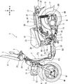
- FIG. 2 is a left side view of the electric motorcycle 1 with main exterior parts removed.
- the vehicle body frame F of the electric motorcycle 1 includes a main frame F2 extending in the vehicle width direction from the head pipe F1 to the lower side of the vehicle body, and a pair of left and right underframes F3 connected to the lower end of the main frame F2 and curved rearward of the vehicle body. And a rising portion F4 rising from the rear end portion of the underframe F3 above the vehicle body, and a pair of left and right rear frames F6 connected to the rising portion F4 and extending rearward of the vehicle body.
- a curved pipe F5 that connects the left and right rising portions F4 is connected to the front portion of the rising portion F4.
- a steering stem 34 is rotatably supported by the head pipe F1.
- the steering handlebar 2 is fixed to the upper end of the steering stem 34, and the bottom bridge 32 that supports the upper end of the front fork 9 is fixed to one lower end.
- the seat 23 is attached to the seat pedestal 29 so as to be openable and closable about the front end of the vehicle body as an axis.
- a battery case 40 that accommodates two main batteries (high-voltage batteries) B1 that supply electric power to the motor M side by side in the vehicle width direction is arranged below the seat pedestal 29.
- the rated voltage of the main battery B1 is, for example, 48V.
- the battery case 40 is housed in the space between the pair of left and right rising portions F4 behind the curved pipe F5.
- the seat lower cowl 24 (see FIG. 1) extends from the front of the curved pipe F5 to the sides of the left and right rising portions F4 so as to cover the front and sides of the battery case 40.
- a storage case 30 for storing a sub-battery (low voltage battery) B2 for supplying electric power to auxiliary devices such as the headlight 7 and electric components such as a fuse is arranged below the low floor 25, a storage case 30 for storing a sub-battery (low voltage battery) B2 for supplying electric power to auxiliary devices such as the headlight 7 and electric components such as a fuse is arranged.
- the rated voltage of the sub-battery B2 is, for example, 12V.
- a cover member 38 that receives the traveling wind from the front of the vehicle body in front of the rear fender 17 is arranged on the rear surface side of the battery case 40.
- a PCU (power control unit) 39 that controls the supply of electric power to the motor M is disposed at a position on the rear side of the battery case 40 that is closer to the upper side.
- the PCU 39 having a plurality of cooling fins is formed in a rectangular box shape in a side view of the vehicle body, and is arranged in a tilted state so that the upper side of the vehicle body is located rearward of the vehicle body lower side.
- the upper side of the PCU 39 which is arranged at a position in front of the vehicle body with respect to the axle S of the rear wheel WR, is accommodated between the rear frames F6 in a side view of the vehicle body, and one lower side is covered by the side wall of the cover member 38. It is being appreciated. As shown in FIG. 1, the rear cowl 21 has a function of covering the upper end of the cover member 38 to the upper end of the rear frame F6 to protect the outer side of the PCU 39 in the vehicle width direction.
- FIG. 3 is a perspective view of the electric motorcycle 1 shown in FIG.
- the windscreen 4 is fixed to the rod-shaped stay member 4b attached to the steering handle 2 by a fastening member 4a.
- a battery case 40 provided inside the lower seat cowl 24 accommodates two main batteries B1 arranged side by side in the vehicle width direction. The main battery B1 can be removed by pulling the handle 41 upward.
- a cross frame F7 that is connected to the lower end of the main frame F2 and that connects the left and right underframes F3 to each other is provided.
- a support frame 43 that extends rearward of the vehicle body and supports the lower surface of the storage case 30 is connected to the center of the cross frame F7 in the vehicle width direction.
- a support plate F8 that supports the low floor 25 is attached to the upper surfaces of the left and right underframes F3.
- a gusset F9 that reinforces the rising portion F4 that curves upward and rearward of the vehicle body is disposed behind the support plate F8 in the vehicle body.
- a brake pedal 26 is provided, the step of which protrudes above the vehicle body from an opening formed in the low floor 25.
- the brake pedal 26 is swingably supported by a pedal swing shaft 42 fixed to a support plate F8 on the right side in the vehicle width direction.
- An operating force distribution mechanism 60 including the brake pedal 26 is arranged inside the pedal swing shaft 42 in the vehicle width direction.
- the electric motorcycle 1 operates the front wheel brake BF by operating the brake lever (see FIG. 13) provided on the steering handle 2 on the right side, while the rear wheel brake BF operates when the brake pedal 26 is operated. It has a front-rear interlocking brake system in which both the wheel brake BR and the front wheel brake BF are activated. Only one front wheel brake cable 406 is connected to the front wheel brake BF.
- the operation force distribution mechanism 60 is connected to the interlocking cable 100 for operating the operation force of the brake pedal 26 by operating the rear wheel brake cable 150 connected to the rear wheel brake BR and the front wheel brake BF.
- the rear wheel brake cable 150 extends from the operating force distribution mechanism 60 to the front of the vehicle body, is curved in front of the main frame F2 to the vehicle body, and is then guided to the rear of the vehicle body along the underframe F3 on the left side in the vehicle width direction.
- the interlocking cable 100 extends from the operating force distribution mechanism 60 to the front of the vehicle body, bends in front of the main frame F2 to the vehicle body, passes through the vehicle body rear side of the underframe F3, and rises above the vehicle body along the main frame F2. Be guided.
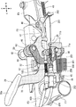
- FIG. 4 is an enlarged perspective view showing the configuration of the brake pedal 26 and its surroundings.
- 5 is a partially enlarged left side view of the electric motorcycle 1 of FIG.
- the pedal swing shaft 42 of the brake pedal 26 is fixed to a pair of left and right fixing members 50 fixed to the support plate F8.
- the brake pedal 26 is swingably supported on a pedal swing shaft 42 fixed to the vehicle body side, and the foot portion 26a provided at the tip of a main body portion 70 extending upward and forward of the vehicle body can be depressed. Then, the front wheel brake BF and the rear wheel brake BR are operated by swinging to the front side of the vehicle body.
- An equalizer 80 which distributes the operating force input to the brake pedal 26 to the rear wheel brake cable 150 and the interlocking cable 100, is pivotally supported at a position of the brake pedal 26 near the bottom of the main body 70. ..
- the equalizer 80 is a plate-shaped member elongated in the vertical direction of the vehicle body.
- the rear wheel brake cable 150 is connected to the lower end of the equalizer 80, and the interlocking cable 100 is connected to the upper end of the equalizer 80.
- a spring support member 71 is fixed to the lower end of the main body 70 of the brake pedal 26, extends below the equalizer 80 toward the center side in the vehicle width direction, and then bends upward in the vehicle body.
- the other end of the return spring 300 that applies a biasing force that returns the brake pedal 26 to the initial position is engaged with the through hole 71a formed in the bottom surface of the spring support member 71.
- One end of the return spring 300 engages with the holder member 44 attached to the cross frame F7.
- the initial position of the brake pedal 26 is defined by the stopper rubber 52 of the rubber holder 51 provided on the support plate F8.
- the holder member 44 is also engaged with one end of a delay spring 301 that pulls the connecting shaft of the interlocking cable 100 connected to the lower end of the equalizer 80 forward of the vehicle body.
- the delay spring 301 has a function of swinging the equalizer 80 clockwise in a side view of the vehicle body to bring it into contact with the stopper member 90.
- the stopper member 90 is a separate member independent of the brake pedal 26, and is fixed to the pedal swing shaft 42 coaxially with a bolt 46 so that the stopper member 90 is not swingable attached to the vehicle body side.
- the position where the equalizer 80 contacts the stopper member 90 becomes the initial position of the equalizer 80. This initial position can be changed depending on the shape of the stopper member 90 and the fixed angle.
- the brake pedal 26 is offset to the left or the right inside the pair of left and right underframes F3, the equalizer 80 is arranged on the inner side in the vehicle width direction of the brake pedal 26, and the delay spring 301 and the return spring are provided.
- the spring 300 is arranged inside the equalizer 80 in the vehicle width direction.
- a cross frame F7 that extends in the vehicle width direction and connects the pair of left and right underframes F3 is arranged in front of the brake pedal 26, so that the operating force distribution mechanism 60 is disposed in the underframe F3 and the cross frame F7. Can be protected by.
- the equalizer 80 and the underframe F3 are arranged so as to overlap each other in a side view of the vehicle body. This makes it possible to protect the equalizer, which affects the operation feeling of the brake pedal, with the underframe.
- a switch spring 251 for pulling the operator of the stop lamp switch 250 is engaged with the through hole 71b formed in the upright portion of the spring support member 71.
- the wiring 252 of the stop lamp switch 250 is routed toward the front upper side of the vehicle body.
- a parking brake mechanism that holds the brake pedal 26 in the depressed position is provided behind the vehicle body of the brake pedal 26.
- a parking brake operator (not shown) provided near the steering handle 2 at a position where the brake pedal 26 is depressed, the hook 47 pivotally supported by the rotary shaft 48 swings forward. Is a mechanism that engages with the brake pedal 26 and locks the brake pedal 26.
- a hook 202 fixed to the end of the inner wire 201 of the parking brake cable 200 is engaged with the hook 47.
- the hook 47 is released. Is configured to swing.
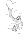
- FIG. 6 is a perspective view of the brake pedal 26.
- a foot portion 26a made of rubber or the like is attached to a main body portion 70 made of a pressed steel plate or the like, and a pipe member 75 pivotally supported by a pedal swing shaft 42 is fixed to an upward extending portion 72.
- the equalizer swing shaft 82 of the equalizer 80 is fixed to the downward extending portion 74, and the spring support member 71 is fixed to the lower end portion of the downward extending portion 74.
- the rearward projecting portion 73 constitutes an engaging portion with which the hook 47 of the parking brake mechanism is engaged.
- the spring support member 71 that extends below the equalizer 80 toward the inside in the vehicle width direction also has a function of protecting the lower portion of the equalizer 80.
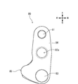
- FIG. 7 is a left side view of the equalizer 80.
- FIG. 8 is a perspective view of the equalizer 80 as viewed from the upper left side of the vehicle body.
- the equalizer 80 made of a metal such as aluminum is provided with a through hole 82a through which the equalizer swing shaft 82 passes, at the substantially center of a plate-like main body 84 having a thickness that is elongated in the vertical direction of the vehicle body.
- An upper connection shaft 81 for connecting the cable 100 and a lower connection shaft 83 for connecting the rear wheel brake cable 150 are attached.
- a contact surface 85 that contacts the stopper member 90 is provided at a front end portion of the main body portion 84 near the lower side.
- the upper connecting shaft 81 to which the interlocking cable 100 is connected projects inward in the vehicle width direction
- the small diameter portion 83b of the lower connecting shaft 83 to which the rear wheel brake cable 150 is connected is outward in the vehicle width direction.
- the upper connecting shaft 81 and the small diameter portion 83b are provided with cotter pin insertion holes 81a and 83c for fixing, respectively.
- An engaging groove 83a with which the other end of the delay spring 301 engages is formed in the lower connecting shaft 83 that protrudes inward of the equalizer 80 in the vehicle width direction.
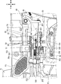
- FIG. 9 is a left side view showing the configuration of the operating force distribution mechanism 60.
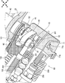
- FIG. 10 is a perspective view of the operating force distribution mechanism 60 with the brake pedal 26 removed.
- the rear end of the interlocking cable 100 is connected to the upper connecting shaft 81 via an end fitting 101 provided with a through hole oriented in the vehicle width direction. Further, the rear wheel brake cable 150 is connected to the lower connecting shaft 83 via the end fitting 151.
- the rear wheel brake BR begins to generate a braking force by further depressing the brake pedal 26, the rear wheel brake cable 150 becomes more difficult to pull, so that the equalizer 80 swings clockwise around the equalizer swing shaft 82.
- the upper connecting shaft 81 moves to the rear of the vehicle body and the pulling of the interlocking cable 100 is started. That is, when the brake pedal 26 is stepped on shallowly, the rear wheel brake BR is activated first, and when the rear wheel brake BR is further depressed from the position where the braking force is generated, the front wheel brake BF is activated. As a result, a natural brake feeling can be obtained.
- the equalizer 80 is arranged below the pedal swing shaft 42 of the brake pedal 26 in the vehicle body, so that the equalizer 80 is arranged above the pedal swing shaft 42 of the brake pedal 26 in the vehicle body.
- the distance between the back surface of the low floor 25 and the pedal swing shaft of the brake pedal 26 can be shortened.
- the floor surface of the low floor 25 can be kept low, and the brake pedal 26 can be downsized.
- one end of the delay spring 301 that biases the swinging motion of the equalizer 80 in one direction is engaged with the vehicle body side, and the other end of the delay spring 301 is attached to the lower connecting shaft 83 of the rear wheel brake cable 150.
- the rear wheel brake cable 150 is connected to the outer side of the lower connecting shaft 83 in the vehicle width direction, and the delay spring is connected to the inner side of the lower connecting shaft 83 with the equalizer 80 in between. 301 can be engaged.
- the size of the equalizer 80 in the height direction can be reduced as compared with a configuration in which the connecting portion of the rear wheel brake cable and the engaging portion of the delay spring are vertically offset.
- the return spring 300 and the delay spring 301 are arranged so as to overlap each other when the vehicle body is viewed from the side, the dimension in the height direction around the brake pedal 26 can be reduced. This makes it possible to further lower the floor surface of the low floor 25 and improve the entry/exitability.
- the engaging portion of the return spring 300 and the engaging portion of the delay spring 301 are arranged close to each other, when the brake pedal 26 is released, the return spring 300 and the delay spring 301 are substantially in synchronization with each other and are in the initial position. As a result, the two types of spring biasing forces can be prevented from affecting the operation feeling of the brake pedal 26.
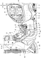
- FIG. 11 is a plan view showing the configuration of the brake pedal 26 and its surroundings.
- FIG. 12 is an enlarged perspective view of the operating force distribution mechanism 60.
- the equalizer 80 is a plate-shaped member that directs the longitudinal direction in the vertical direction of the vehicle body, and the rear wheel brake cable 150 is connected to one surface side of the equalizer 80 and the interlocking cable is connected to the other surface side of the equalizer 80. 100 are connected. Thereby, the interference between the rear wheel brake cable 150 and the interlocking cable 100 can be prevented.
- FIG. 13 is a plan view showing the configuration of the brake lever 400 and its surroundings.
- a brake lever 400 is attached to the steering handlebar 2 on the right side.
- a lever holder 402 which pivotally supports a brake lever 400, is fixed to a handle pipe 2b that constitutes the steering handlebar 2.
- a switch box 413 including various handle switches is fixed to the outer side of the lever holder 402 in the vehicle width direction, and a handle provided with a heater operated by electric power supplied from the harness 408 is provided to the outer side of the switch box 413 in the vehicle width direction.
- the grip 2a is attached.
- a stay holder 407 of a stay member 4b that supports the windscreen 4 is attached to the inside of the lever holder 402 in the vehicle width direction.
- a lever swing shaft 401 for swingably supporting the brake lever 400 and a brake lever 400 for holding the brake lever 400 in a gripped position.
- An operator swing shaft 405 of the lock operator 403 is arranged.
- the brake lever 400 is biased by a return spring 415 that is wound coaxially with the lever swing shaft 401 to return it to its initial position.
- the lock operator 403 is given an urging force in a direction to return it to the initial position by a return spring 404 that is wound coaxially with the operator swing shaft 405.
- the front wheel brake cable 406 is connected to the front end of the lever holder 402.
- a knocker 500 (indicated by a hatched hatching portion) that transmits an operating force input via the interlocking cable 100 to the front wheel brake cable 406 is provided.
- FIG. 14 is a perspective view of the brake lever 400 seen from the lower surface side.
- the body portion 450 of the brake lever 400 made of metal such as aluminum has a through hole 453 through which the lever swing shaft 401 passes, a pressing portion 452 that presses a part of the knocker 500 when the brake lever 400 is operated, and the brake lever 400. And an engaging recess 454 with which the lock operator 403 is engaged when locked.
- FIG. 15 is a plan view of the knocker 500.
- 16 is a rear view of the same
- FIG. 17 is a left side view of the same
- FIG. 18 is a bottom view of the same.
- the knocker 500 formed of a metal such as aluminum includes a knocker main body 501 having a through hole 502 through which the lever swing shaft 401 passes, and a long plate-shaped extending portion 504 extending from the knocker main body 501 rearward of the vehicle body. Have and.
- a through hole 505 for connecting the interlocking cable 100 is formed at the rear end of the extending portion 504.
- An engagement groove 506 for accommodating the inner wire (see FIG. 19) of the front wheel brake cable 406 is formed on the front side of the knocker body 501 with respect to the vehicle body, and is provided at the end of the inner wire on the back side of the knocker body 501.
- a circular recess 508 for accommodating the Tyco is formed.
- An abutting portion 503 that abuts the pressing portion 452 of the brake lever 400 is formed on the front surface portion of the knocker main body portion 501 on the outer side in the vehicle width direction.
- the extending portion 504 has a shape extending from the lower surface of the knocker main body portion 501 downward and rearward of the vehicle body. In the vicinity of the circular recess 508, a positioning protrusion 507 that abuts the lever holder 402 and defines the initial position of the knocker 500 is provided.
- FIG. 19 is a bottom view showing the configuration of knocker 500 and its surroundings.
- FIG. 20 is a perspective view of the knocker 500 and its surroundings as seen obliquely from the upper right rear of the vehicle body.
- the knocker 500 can swing with respect to both the lever holder 402 and the brake lever 400 by the lever swing shaft 401.
- the drum 421 fixed to one end of the inner wire 420 of the front wheel brake wire 406 is housed.
- a tow shaft 156 that engages with the tow member 154 tow by the interlocking cable 100 is fixed to the vehicle body front side end of the extension 504.
- the knocker 500 is swung in one direction to operate the front wheel brake BF.
- the end of the interlocking cable 100 is connected to the tubular member 152 that houses the coil spring 153, and the operating force transmitted to the interlocking cable 100 is transmitted to the traction member 154 via the coil spring 153.
- a traction member 154 formed by bending a single plate member is formed with an elongated hole 155 in which a traction shaft 156 can slide, and thus a slide mechanism of the traction shaft 156 is configured. That is, when the brake lever 400 is operated, the pulling shaft 156 only slides in the elongated hole 155, and the interlocking cable 100 is not affected.
- the front wheel brake cable 406 and the interlocking cable 100 are connected to the knocker 500 at positions facing each other with the lever swing shaft 401 interposed therebetween.
- the outer tube is not divided unlike the configuration in which the operating force is interposed in the middle position of the front wheel brake cable 406, and the front-rear interlocking brake system can be configured while suppressing an increase in the number of parts.
- the front wheel brake cable 406 does not bend due to the operation of the interlocking cable, it is not necessary to secure an extra clearance space for the front wheel brake cable 406, and the vehicle body can be downsized.
- the brake pedal 26 can be operated. Accordingly, it is possible to obtain a brake system in which the knocker 500 swings to operate the front wheel brake BF, and the knocker 500 swings to operate the front wheel brake BF in response to the operation of the brake lever 400.
- the knocker 500 is elongated in the front-rear direction of the vehicle body, the base portion of the brake lever 400 is downsized, and it is easy to obtain the same appearance and operation feeling as a brake lever in a normal brake system.
- the interlocking cable 100 is connected to the knocker 500 on the vehicle body rear side of the front wheel brake cable 406 that is connected to the vehicle body front side of the knocker 500, the interlocking cable 100 and the front wheel brake cable 406 are connected to the steering wheel 2. It is possible to prevent crossing in the vicinity of and to increase the degree of freedom in arranging both cables.
- the brake lever 400 is arranged at the same height as the steering handle 2 by arranging the connecting portion between the knocker 500 and the interlocking cable 100 offset from the connecting portion of the front wheel brake cable 406 below the vehicle body.
- the operability of the brake lever 400 can be maintained, and the connecting portion of the interlocking cable 100 can be offset below the brake lever 400 to make it difficult to visually recognize the knocker 500 and the interlocking cable 100 from the outside. it can.
- the initial positions of the knocker 500 and the brake lever 400 can be defined with a simple configuration. ..
- FIG. 21 is a perspective view of the steering handlebar 2 with the knuckle guard 600 attached.
- the handle cover 33 that covers the central portion of the steering handlebar 2 in the vehicle width direction does not cover the portion outside the switch box 413 in the vehicle width direction, and the knocker 500 is configured to be exposed to the outside.
- the knocker 500 is elongated in the front-rear direction of the vehicle body, it is possible to prevent the handle cover 33 from increasing in size and facilitate maintenance around the brake lever 400.
- the knocker 500 is arranged on the back surface side of the brake lever 400, the range in which the knocker 500 can be visually recognized from the outside is small, but as shown in this figure, a portion not covered by the handle cover 33 is provided.
- the front/rear interlocking brake device according to the present invention is not limited to an electric motorcycle, but can be applied to a motorcycle having an internal combustion engine as a power source, a saddle-ride type three-wheel vehicle, a four-wheel vehicle, and the like.
- SYMBOLS 1 Electric motorcycle (saddle-type vehicle), 2... Steering handle, 42... Pedal rocking axis, 23... Seat, 25... Low floor, 26... Brake pedal, 33... Handle cover, 80... Equalizer, 82... Equalizer swing shaft, 83... Rear wheel brake cable connecting shaft, 90... Stopper member, 100... Interlocking cable, 150... Rear wheel brake cable, 300... Return spring, 301... Delay spring, 400... Brake lever, 401... Lever swing shaft, 406... Front wheel brake cable, 420... Inner wire, 402... Lever holder, 500... Knocker, 503... Abutment portion, 507... Positioning protrusion, BF... Front wheel brake, BR... Rear wheel brake, F3... Underframe , F7...Cross frame
Landscapes
- Engineering & Computer Science (AREA)
- Mechanical Engineering (AREA)
- Transportation (AREA)
- Transmission Of Braking Force In Braking Systems (AREA)
- Mechanical Control Devices (AREA)
- Braking Elements And Transmission Devices (AREA)
Abstract
Description
Claims (10)
- 操向ハンドル(2)にブレーキレバー(400)が配設されると共に、前記操向ハンドル(2)とシート(23)との間に設けられる低床フロア(25)にブレーキペダル(26)が配設される鞍乗型車両(1)に適用される鞍乗型車両の前後連動ブレーキ装置において、
前記ブレーキペダル(26)に入力された操作力を、後輪ブレーキ(BR)および前輪ブレーキ(BF)に分配して伝達するイコライザ(80)を具備し、
前記イコライザ(80)が、前記ブレーキペダル(26)のペダル揺動軸(42)より車体下方に配設されていることを特徴とする鞍乗型車両の前後連動ブレーキ装置。 - 前記イコライザ(80)は、イコライザ揺動軸(82)によって前記ブレーキペダル(26)に揺動可能に軸支されており、
前記イコライザ(80)に、前記ブレーキペダル(26)の操作力を前記後輪ブレーキ(BR)に伝達する後輪ブレーキケーブル(150)と、前記ブレーキペダル(26)の操作力を前記前輪ブレーキ(BF)に伝達する連動用ケーブル(100)とが連結されていることを特徴とする請求項1に記載の鞍乗型車両の前後連動ブレーキ装置。 - 前記イコライザ(80)の揺動動作を一方向に付勢するディレイスプリング(301)の一端部が車体側に係合されており、
前記後輪ブレーキケーブル(150)の連結軸(83)に、前記ディレイスプリング(301)の他端部が係合することを特徴とする請求項2に記載の鞍乗型車両の前後連動ブレーキ装置。 - 前記ブレーキペダル(26)を初期位置に戻す方向に付勢するリターンスプリング(300)を具備し、
前記リターンスプリング(300)と前記ディレイスプリング(301)とが、車体側面視で重なるように配設されていることを特徴とする請求項3に記載の鞍乗型車両の前後連動ブレーキ装置。 - 前記イコライザ(80)が、車体上下方向に長手方向を指向させる板状部材であり、
前記イコライザ(80)の一面側に前記後輪ブレーキケーブル(150)が連結されると共に、前記イコライザ(80)の他面側に前記連動用ケーブル(100)が連結されることを特徴とする請求項2ないし4のいずれかに記載の鞍乗型車両の前後連動ブレーキ装置。 - 前記イコライザ(80)の初期角度を規定するストッパ部材(90)を備え、
前記ストッパ部材(90)が、単独で車体に固定されていることを特徴とする請求項2ないし5のいずれかに記載の鞍乗型車両の前後連動ブレーキ装置。 - 前記鞍乗型車両(1)は、前記低床フロア(25)を支持する左右一対のアンダフレーム(F3)を有し、
前記ブレーキペダル(26)は、前記左右一対のアンダフレーム(F3)の内側で左右いずれかにオフセット配置されており、
前記イコライザ(80)は、前記ブレーキペダル(26)より車幅方向内側に配設されていることを特徴とする請求項2ないし6のいずれかに記載の鞍乗型車両の前後連動ブレーキ装置。 - 前記ディレイスプリング(301)および前記リターンスプリング(300)が、前記イコライザ(80)より車幅方向内側に配設されていることを特徴とする請求項7に記載の鞍乗型車両の前後連動ブレーキ装置。
- 前記ブレーキペダル(26)の車体前方に、車幅方向に延出して前記左右一対のアンダフレーム(F3)を連結するクロスフレーム(F7)が配設されていることを特徴とする請求項7または8に記載の鞍乗型車両の前後連動ブレーキ装置。
- 前記イコライザ(80)と前記アンダフレーム(F3)とが、車体側面視で重なることを特徴とする請求項9に記載の鞍乗型車両の前後連動ブレーキ装置。
Priority Applications (3)
| Application Number | Priority Date | Filing Date | Title |
|---|---|---|---|
| CN201980085414.XA CN113226908B (zh) | 2018-12-27 | 2019-08-07 | 跨骑型车辆的前后连动制动装置 |
| BR112021010417-8A BR112021010417A2 (pt) | 2018-12-27 | 2019-08-07 | Sistema de freio de intertravamento dianteiro-traseiro para veículo de montar em selim |
| JP2020562336A JP7061692B2 (ja) | 2018-12-27 | 2019-08-07 | 鞍乗型車両の前後連動ブレーキ装置 |
Applications Claiming Priority (2)
| Application Number | Priority Date | Filing Date | Title |
|---|---|---|---|
| JP2018-244448 | 2018-12-27 | ||
| JP2018244448 | 2018-12-27 |
Publications (1)
| Publication Number | Publication Date |
|---|---|
| WO2020136980A1 true WO2020136980A1 (ja) | 2020-07-02 |
Family
ID=71127006
Family Applications (1)
| Application Number | Title | Priority Date | Filing Date |
|---|---|---|---|
| PCT/JP2019/031258 Ceased WO2020136980A1 (ja) | 2018-12-27 | 2019-08-07 | 鞍乗型車両の前後連動ブレーキ装置 |
Country Status (4)
| Country | Link |
|---|---|
| JP (1) | JP7061692B2 (ja) |
| CN (1) | CN113226908B (ja) |
| BR (1) | BR112021010417A2 (ja) |
| WO (1) | WO2020136980A1 (ja) |
Families Citing this family (1)
| Publication number | Priority date | Publication date | Assignee | Title |
|---|---|---|---|---|
| CN119929049B (zh) * | 2025-03-21 | 2025-10-28 | 江门速龙机车制造有限公司 | 一种脚踏式前后分段联动刹车系统 |
Citations (3)
| Publication number | Priority date | Publication date | Assignee | Title |
|---|---|---|---|---|
| JP2014012462A (ja) * | 2012-07-04 | 2014-01-23 | Yamaha Motor Co Ltd | 鞍乗型車両用ブレーキ装置及び鞍乗型車両 |
| JP2015160547A (ja) * | 2014-02-27 | 2015-09-07 | 本田技研工業株式会社 | 自動二輪車 |
| JP2018177201A (ja) * | 2017-04-14 | 2018-11-15 | ヤマハ発動機株式会社 | 鞍乗型車両 |
Family Cites Families (10)
| Publication number | Priority date | Publication date | Assignee | Title |
|---|---|---|---|---|
| CN101918267B (zh) * | 2008-01-31 | 2012-10-24 | 本田技研工业株式会社 | 摩托车的联动制动装置 |
| JP5057231B2 (ja) * | 2008-01-31 | 2012-10-24 | 本田技研工業株式会社 | 自動二輪車の連動ブレーキ装置 |
| JP5887241B2 (ja) * | 2012-09-27 | 2016-03-16 | 本田技研工業株式会社 | 自動二輪車の連動ブレーキ装置 |
| JP6306896B2 (ja) * | 2014-02-27 | 2018-04-04 | 本田技研工業株式会社 | 自動二輪車 |
| CN108025793B (zh) * | 2015-09-30 | 2020-01-07 | 本田技研工业株式会社 | 鞍乘型车辆和前后联动制动机构 |
| WO2017057594A1 (ja) * | 2015-09-30 | 2017-04-06 | 本田技研工業株式会社 | 鞍乗り型車両 |
| BR112018004365B1 (pt) * | 2015-09-30 | 2022-08-30 | Honda Motor Co., Ltd | Dispositivo de freio de intertravamento de veículo |
| BR112018003358B1 (pt) * | 2015-09-30 | 2022-12-06 | Honda Motor Co., Ltd | Dispositivo de frenagem combinado para motocicletas |
| WO2017110587A1 (ja) * | 2015-12-22 | 2017-06-29 | 本田技研工業株式会社 | 自動二輪車 |
| JP6796196B2 (ja) * | 2017-04-25 | 2020-12-02 | 本田技研工業株式会社 | 鞍乗り型車両の前後連動ブレーキ装置 |
-
2019
- 2019-08-07 BR BR112021010417-8A patent/BR112021010417A2/pt not_active Application Discontinuation
- 2019-08-07 CN CN201980085414.XA patent/CN113226908B/zh active Active
- 2019-08-07 WO PCT/JP2019/031258 patent/WO2020136980A1/ja not_active Ceased
- 2019-08-07 JP JP2020562336A patent/JP7061692B2/ja active Active
Patent Citations (3)
| Publication number | Priority date | Publication date | Assignee | Title |
|---|---|---|---|---|
| JP2014012462A (ja) * | 2012-07-04 | 2014-01-23 | Yamaha Motor Co Ltd | 鞍乗型車両用ブレーキ装置及び鞍乗型車両 |
| JP2015160547A (ja) * | 2014-02-27 | 2015-09-07 | 本田技研工業株式会社 | 自動二輪車 |
| JP2018177201A (ja) * | 2017-04-14 | 2018-11-15 | ヤマハ発動機株式会社 | 鞍乗型車両 |
Also Published As
| Publication number | Publication date |
|---|---|
| JPWO2020136980A1 (ja) | 2021-10-07 |
| JP7061692B2 (ja) | 2022-04-28 |
| CN113226908B (zh) | 2022-08-23 |
| CN113226908A (zh) | 2021-08-06 |
| BR112021010417A2 (pt) | 2021-08-24 |
Similar Documents
| Publication | Publication Date | Title |
|---|---|---|
| JP5871382B2 (ja) | 鞍乗型車両のハーネス配策構造 | |
| JP7018419B2 (ja) | 鞍乗型車両 | |
| JP5919242B2 (ja) | 鞍乗型車両 | |
| JP6670814B2 (ja) | 鞍乗り型車両 | |
| TWI725293B (zh) | 支持構件及包含其之車輛 | |
| CN112752708B (zh) | 骑乘型车辆的电池装卸构造 | |
| JP7061692B2 (ja) | 鞍乗型車両の前後連動ブレーキ装置 | |
| JP6793177B2 (ja) | 鞍乗型車両の前後連動ブレーキ装置 | |
| JP4612005B2 (ja) | スクータ型車両のフットブレーキ構造 | |
| JP6636645B2 (ja) | 鞍乗り型車両 | |
| JP7343638B1 (ja) | 鞍乗型車両 | |
| WO2017056281A1 (ja) | 鞍乗り型車両の連動ブレーキ装置 | |
| EP2048071B1 (en) | Straddle-type vehicle | |
| CN108883807B (zh) | 鞍乘式车辆 | |
| JP4391795B2 (ja) | 二輪車両及び三輪車両用パーキングレバーの配置構造 | |
| JP7791230B2 (ja) | 鞍乗り型車両のブレーキケーブル保護構造 | |
| JP6961006B2 (ja) | 鞍乗型車両の支持部材構造 | |
| JP6936829B2 (ja) | 鞍乗型車両 | |
| JP7712814B2 (ja) | 鞍乗型車両のメータブラケット | |
| JP6761487B2 (ja) | 鞍乗型車両 | |
| CN114728682B (zh) | 跨骑型车辆的连动制动装置 | |
| WO2018198827A1 (ja) | 鞍乗り型車両の前後連動ブレーキ装置 | |
| WO2022209890A1 (ja) | 鞍乗型車両 | |
| JP2017165207A (ja) | 鞍乗型車両の後部装置 | |
| JP2025090444A (ja) | 鞍乗り型車両 |
Legal Events
| Date | Code | Title | Description |
|---|---|---|---|
| 121 | Ep: the epo has been informed by wipo that ep was designated in this application |
Ref document number: 19904793 Country of ref document: EP Kind code of ref document: A1 |
|
| ENP | Entry into the national phase |
Ref document number: 2020562336 Country of ref document: JP Kind code of ref document: A |
|
| REG | Reference to national code |
Ref country code: BR Ref legal event code: B01A Ref document number: 112021010417 Country of ref document: BR |
|
| NENP | Non-entry into the national phase |
Ref country code: DE |
|
| ENP | Entry into the national phase |
Ref document number: 112021010417 Country of ref document: BR Kind code of ref document: A2 Effective date: 20210528 |
|
| 122 | Ep: pct application non-entry in european phase |
Ref document number: 19904793 Country of ref document: EP Kind code of ref document: A1 |