WO2020116312A1 - 電池システム - Google Patents
電池システム Download PDFInfo
- Publication number
- WO2020116312A1 WO2020116312A1 PCT/JP2019/046587 JP2019046587W WO2020116312A1 WO 2020116312 A1 WO2020116312 A1 WO 2020116312A1 JP 2019046587 W JP2019046587 W JP 2019046587W WO 2020116312 A1 WO2020116312 A1 WO 2020116312A1
- Authority
- WO
- WIPO (PCT)
- Prior art keywords
- battery
- temperature
- identification information
- monitoring unit
- voltage
- Prior art date
- Legal status (The legal status is an assumption and is not a legal conclusion. Google has not performed a legal analysis and makes no representation as to the accuracy of the status listed.)
- Ceased
Links
Images


Classifications
-
- H—ELECTRICITY
- H01—ELECTRIC ELEMENTS
- H01M—PROCESSES OR MEANS, e.g. BATTERIES, FOR THE DIRECT CONVERSION OF CHEMICAL ENERGY INTO ELECTRICAL ENERGY
- H01M10/00—Secondary cells; Manufacture thereof
- H01M10/42—Methods or arrangements for servicing or maintenance of secondary cells or secondary half-cells
- H01M10/48—Accumulators combined with arrangements for measuring, testing or indicating the condition of cells, e.g. the level or density of the electrolyte
- H01M10/482—Accumulators combined with arrangements for measuring, testing or indicating the condition of cells, e.g. the level or density of the electrolyte for several batteries or cells simultaneously or sequentially
-
- G—PHYSICS
- G01—MEASURING; TESTING
- G01R—MEASURING ELECTRIC VARIABLES; MEASURING MAGNETIC VARIABLES
- G01R31/00—Arrangements for testing electric properties; Arrangements for locating electric faults; Arrangements for electrical testing characterised by what is being tested not provided for elsewhere
- G01R31/36—Arrangements for testing, measuring or monitoring the electrical condition of accumulators or electric batteries, e.g. capacity or state of charge [SoC]
- G01R31/382—Arrangements for monitoring battery or accumulator variables, e.g. SoC
- G01R31/3835—Arrangements for monitoring battery or accumulator variables, e.g. SoC involving only voltage measurements
-
- G—PHYSICS
- G01—MEASURING; TESTING
- G01R—MEASURING ELECTRIC VARIABLES; MEASURING MAGNETIC VARIABLES
- G01R31/00—Arrangements for testing electric properties; Arrangements for locating electric faults; Arrangements for electrical testing characterised by what is being tested not provided for elsewhere
- G01R31/36—Arrangements for testing, measuring or monitoring the electrical condition of accumulators or electric batteries, e.g. capacity or state of charge [SoC]
- G01R31/396—Acquisition or processing of data for testing or for monitoring individual cells or groups of cells within a battery
-
- H—ELECTRICITY
- H01—ELECTRIC ELEMENTS
- H01M—PROCESSES OR MEANS, e.g. BATTERIES, FOR THE DIRECT CONVERSION OF CHEMICAL ENERGY INTO ELECTRICAL ENERGY
- H01M10/00—Secondary cells; Manufacture thereof
- H01M10/42—Methods or arrangements for servicing or maintenance of secondary cells or secondary half-cells
- H01M10/425—Structural combination with electronic components, e.g. electronic circuits integrated to the outside of the casing
-
- H—ELECTRICITY
- H01—ELECTRIC ELEMENTS
- H01M—PROCESSES OR MEANS, e.g. BATTERIES, FOR THE DIRECT CONVERSION OF CHEMICAL ENERGY INTO ELECTRICAL ENERGY
- H01M10/00—Secondary cells; Manufacture thereof
- H01M10/42—Methods or arrangements for servicing or maintenance of secondary cells or secondary half-cells
- H01M10/48—Accumulators combined with arrangements for measuring, testing or indicating the condition of cells, e.g. the level or density of the electrolyte
- H01M10/486—Accumulators combined with arrangements for measuring, testing or indicating the condition of cells, e.g. the level or density of the electrolyte for measuring temperature
-
- H—ELECTRICITY
- H01—ELECTRIC ELEMENTS
- H01M—PROCESSES OR MEANS, e.g. BATTERIES, FOR THE DIRECT CONVERSION OF CHEMICAL ENERGY INTO ELECTRICAL ENERGY
- H01M50/00—Constructional details or processes of manufacture of the non-active parts of electrochemical cells other than fuel cells, e.g. hybrid cells
- H01M50/50—Current conducting connections for cells or batteries
- H01M50/502—Interconnectors for connecting terminals of adjacent batteries; Interconnectors for connecting cells outside a battery casing
- H01M50/509—Interconnectors for connecting terminals of adjacent batteries; Interconnectors for connecting cells outside a battery casing characterised by the type of connection, e.g. mixed connections
- H01M50/51—Connection only in series
-
- H—ELECTRICITY
- H02—GENERATION; CONVERSION OR DISTRIBUTION OF ELECTRIC POWER
- H02J—CIRCUIT ARRANGEMENTS OR SYSTEMS FOR SUPPLYING OR DISTRIBUTING ELECTRIC POWER; SYSTEMS FOR STORING ELECTRIC ENERGY
- H02J7/00—Circuit arrangements for charging or depolarising batteries or for supplying loads from batteries
- H02J7/00032—Circuit arrangements for charging or depolarising batteries or for supplying loads from batteries characterised by data exchange
- H02J7/00036—Charger exchanging data with battery
-
- H—ELECTRICITY
- H02—GENERATION; CONVERSION OR DISTRIBUTION OF ELECTRIC POWER
- H02J—CIRCUIT ARRANGEMENTS OR SYSTEMS FOR SUPPLYING OR DISTRIBUTING ELECTRIC POWER; SYSTEMS FOR STORING ELECTRIC ENERGY
- H02J7/00—Circuit arrangements for charging or depolarising batteries or for supplying loads from batteries
- H02J7/0013—Circuit arrangements for charging or depolarising batteries or for supplying loads from batteries acting upon several batteries simultaneously or sequentially
-
- H—ELECTRICITY
- H02—GENERATION; CONVERSION OR DISTRIBUTION OF ELECTRIC POWER
- H02J—CIRCUIT ARRANGEMENTS OR SYSTEMS FOR SUPPLYING OR DISTRIBUTING ELECTRIC POWER; SYSTEMS FOR STORING ELECTRIC ENERGY
- H02J7/00—Circuit arrangements for charging or depolarising batteries or for supplying loads from batteries
- H02J7/0047—Circuit arrangements for charging or depolarising batteries or for supplying loads from batteries with monitoring or indicating devices or circuits
-
- G—PHYSICS
- G01—MEASURING; TESTING
- G01R—MEASURING ELECTRIC VARIABLES; MEASURING MAGNETIC VARIABLES
- G01R31/00—Arrangements for testing electric properties; Arrangements for locating electric faults; Arrangements for electrical testing characterised by what is being tested not provided for elsewhere
- G01R31/36—Arrangements for testing, measuring or monitoring the electrical condition of accumulators or electric batteries, e.g. capacity or state of charge [SoC]
- G01R31/374—Arrangements for testing, measuring or monitoring the electrical condition of accumulators or electric batteries, e.g. capacity or state of charge [SoC] with means for correcting the measurement for temperature or ageing
-
- H—ELECTRICITY
- H01—ELECTRIC ELEMENTS
- H01M—PROCESSES OR MEANS, e.g. BATTERIES, FOR THE DIRECT CONVERSION OF CHEMICAL ENERGY INTO ELECTRICAL ENERGY
- H01M10/00—Secondary cells; Manufacture thereof
- H01M10/42—Methods or arrangements for servicing or maintenance of secondary cells or secondary half-cells
- H01M10/425—Structural combination with electronic components, e.g. electronic circuits integrated to the outside of the casing
- H01M2010/4271—Battery management systems including electronic circuits, e.g. control of current or voltage to keep battery in healthy state, cell balancing
-
- H—ELECTRICITY
- H02—GENERATION; CONVERSION OR DISTRIBUTION OF ELECTRIC POWER
- H02J—CIRCUIT ARRANGEMENTS OR SYSTEMS FOR SUPPLYING OR DISTRIBUTING ELECTRIC POWER; SYSTEMS FOR STORING ELECTRIC ENERGY
- H02J7/00—Circuit arrangements for charging or depolarising batteries or for supplying loads from batteries
- H02J7/0029—Circuit arrangements for charging or depolarising batteries or for supplying loads from batteries with safety or protection devices or circuits
- H02J7/00302—Overcharge protection
-
- H—ELECTRICITY
- H02—GENERATION; CONVERSION OR DISTRIBUTION OF ELECTRIC POWER
- H02J—CIRCUIT ARRANGEMENTS OR SYSTEMS FOR SUPPLYING OR DISTRIBUTING ELECTRIC POWER; SYSTEMS FOR STORING ELECTRIC ENERGY
- H02J7/00—Circuit arrangements for charging or depolarising batteries or for supplying loads from batteries
- H02J7/0029—Circuit arrangements for charging or depolarising batteries or for supplying loads from batteries with safety or protection devices or circuits
- H02J7/00306—Overdischarge protection
-
- Y—GENERAL TAGGING OF NEW TECHNOLOGICAL DEVELOPMENTS; GENERAL TAGGING OF CROSS-SECTIONAL TECHNOLOGIES SPANNING OVER SEVERAL SECTIONS OF THE IPC; TECHNICAL SUBJECTS COVERED BY FORMER USPC CROSS-REFERENCE ART COLLECTIONS [XRACs] AND DIGESTS
- Y02—TECHNOLOGIES OR APPLICATIONS FOR MITIGATION OR ADAPTATION AGAINST CLIMATE CHANGE
- Y02E—REDUCTION OF GREENHOUSE GAS [GHG] EMISSIONS, RELATED TO ENERGY GENERATION, TRANSMISSION OR DISTRIBUTION
- Y02E60/00—Enabling technologies; Technologies with a potential or indirect contribution to GHG emissions mitigation
- Y02E60/10—Energy storage using batteries
-
- Y—GENERAL TAGGING OF NEW TECHNOLOGICAL DEVELOPMENTS; GENERAL TAGGING OF CROSS-SECTIONAL TECHNOLOGIES SPANNING OVER SEVERAL SECTIONS OF THE IPC; TECHNICAL SUBJECTS COVERED BY FORMER USPC CROSS-REFERENCE ART COLLECTIONS [XRACs] AND DIGESTS
- Y02—TECHNOLOGIES OR APPLICATIONS FOR MITIGATION OR ADAPTATION AGAINST CLIMATE CHANGE
- Y02T—CLIMATE CHANGE MITIGATION TECHNOLOGIES RELATED TO TRANSPORTATION
- Y02T10/00—Road transport of goods or passengers
- Y02T10/60—Other road transportation technologies with climate change mitigation effect
- Y02T10/70—Energy storage systems for electromobility, e.g. batteries
Definitions
- the present disclosure relates to a battery system.
- a battery system including a plurality of battery modules is known in order to cope with a wide range of electrification in, for example, an electric vehicle (for example, Patent Document 1).
- the control unit that controls each battery system needs to identify each battery module in order to monitor the state of charge of each battery module and perform a failure diagnosis.
- unique identification information is set in advance in the monitoring unit that monitors the assembled battery, and the control unit identifies each battery module using this identification information.
- the monitoring unit included in each battery module be shared to reduce costs.
- the identification information set in each monitoring unit is different from each other, there is a problem that the monitoring unit included in each battery module cannot be shared.
- the present disclosure has been made to solve the above problems, and an object thereof is to provide a battery system in which a monitoring unit included in each battery module can be shared.
- the present disclosure is a battery system including a plurality of battery modules, wherein each of the battery modules includes an assembled battery having a series connection body of a plurality of battery cells, a monitoring unit that monitors the assembled battery, and a monitoring unit.
- the battery module includes a monitoring unit and an external member electrically connected to the monitoring unit, and the monitoring unit provides different identification information for each battery module based on an electric signal input from the external member. To generate. Since the monitoring unit can generate the identification information based on the electric signal input from the external member, the identification information does not need to be set inside. As a result, the monitoring unit can be shared by the plurality of battery modules that form the battery system.
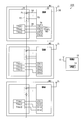
- FIG. 1 is a configuration diagram showing an outline of a vehicle power supply system according to a first embodiment
- FIG. 2 is a flowchart showing the identification process and the identification information generation process
- FIG. 3 is a diagram showing a relationship between the battery module and the identification information according to the first embodiment
- FIG. 4 is a diagram showing temperature characteristics of temperature data and out-of-range data
- FIG. 5 is a configuration diagram showing an outline of a power supply system for a vehicle according to the second embodiment
- FIG. 6 is a diagram showing temperature characteristics of the first temperature data and the second temperature data
- FIG. 7 is a diagram showing a relationship between the battery module and the identification information according to the second embodiment
- FIG. 8 is a configuration diagram showing an outline of a vehicle power supply system according to the third embodiment.
- the battery system 100 of this embodiment is mounted on a vehicle.
- the battery system 100 includes three battery modules M1 to M3 and a control unit 10.
- Each of the battery modules M1 to M3 includes a cell module 20 and a monitoring unit 30.
- the cell module 20 includes an assembled battery 22 having a series connection body of a plurality of battery cells 24. Near the assembled battery 22, three temperature sensors THA1 to THA3 for detecting the temperature of the assembled battery 22 are provided. Each of the temperature sensors THA1 to THA3 detects the temperature of different parts of the battery pack 22 and outputs a voltage signal according to the detected temperature. As the temperature sensors THA1 to THA3, for example, a temperature sensitive diode or a thermistor can be used. In the present embodiment, the temperature sensors THA1 to THA3 correspond to “external members”.
- the monitoring unit 30 monitors the assembled battery 22.
- the monitoring unit 30 is connected to both electrodes of each battery cell 24 forming the assembled battery 22 via a detection line 32, detects the voltage (inter-terminal voltage) of each battery cell 24, and detects the voltage in each battery cell 24.
- the cell voltage data VD which is the corresponding voltage signal is acquired.
- the monitoring unit 30 is provided with a connector 34.
- the connector 34 has four terminals CH1 to CH4 connectable to the temperature sensors THA1 to THA3.
- Electrical wiring 36 extending from the temperature sensors THA1 to THA3 is connected to the connector 34, whereby the monitoring unit 30 and the temperature sensors THA1 to THA3 are electrically connected.
- the monitoring unit 30 acquires the temperature data TDA1 to TDA3 based on the voltage signals input from the temperature sensors THA1 to THA3 via the connector 34.
- the electric wiring 36 is connected to the terminals CH1 to CH4 of the connector 34 on a one-to-one basis.
- the number of terminals CH1 to CH4 of the connector 34 is one more than the number of temperature sensors THA1 to THA3. Therefore, in the connector 34, any one of the terminals CH1 to CH4 becomes an empty terminal that is not connected to the temperature sensors THA1 to THA3.
- the terminals CH1 to CH4 of the connector 34 which terminal is to be an empty terminal can be freely set by an operator when manufacturing the battery modules M1 to M3.
- the monitoring unit 30 includes a communication circuit 38, and wirelessly transmits the acquired cell voltage data VD and temperature data TDA1 to TDA3 to the control unit 10.
- the monitoring unit 30 also wirelessly receives various commands from the control unit 10 via the communication circuit 38.
- the control unit 10 is mainly composed of a microcomputer including a CPU, a ROM, a RAM, and the like, and individually controls the battery modules M1 to M3 by executing various control programs stored in the ROM.
- the control unit 10 is configured to be able to communicate with the monitoring unit 30 of each of the battery modules M1 to M3. Specifically, the control unit 10 includes the communication circuit 12, and wirelessly receives the cell voltage data VD and the temperature data TDA1 to TDA3 wirelessly transmitted by the monitoring unit 30. The control unit 10 controls the battery pack 22 using the received cell voltage data VD and temperature data TDA1 to TDA3. For example, the control unit 10 uses the received cell voltage data VD and temperature data TDA1 to TDA3 to calculate the state of charge (SOC) of the battery pack 22. Then, a command for preventing the assembled battery 22 from being overcharged or overdischarged is wirelessly transmitted to the monitoring unit 30 via the communication circuit 12.
- SOC state of charge
- the control unit 10 needs to identify each of the battery modules M1 to M3 in order to monitor the state of charge of each of the battery modules M1 to M3 and perform a failure diagnosis. For example, let us consider a case where a unique identification information ID is set in the monitoring unit 30 in each of the battery modules M1 to M3.
- the form of setting the identification information ID includes a form in which the storage unit of the monitoring unit 30 stores the identification information ID.
- the control unit 10 can identify each of the battery modules M1 to M3 by acquiring the identification information ID set in the monitoring unit 30 by wireless communication with the monitoring unit 30.
- the monitoring unit 30 included in each of the battery modules M1 to M3 be shared in order to reduce costs.
- different identification information IDs are set for the battery modules M1 to M3 in the monitoring unit 30, there is a problem that the monitoring unit 30 cannot be shared in each of the battery modules M1 to M3. ..
- the monitoring unit 30 in order to solve the above problem, the monitoring unit 30 generates different identification information ID for each of the battery modules M1 to M3 based on the voltage signal input from the temperature sensors THA1 to THA3. To do. Specifically, the connection patterns of the temperature sensors THA1 to THA3 and the terminals CH1 to CH4 of the connector 34 are different for each of the battery modules M1 to M3, and the empty terminals not connected to the temperature sensors THA1 to THA3 are set to be different. ing. Therefore, the signals input to the plurality of terminals CH1 to CH4 are different for each of the battery modules M1 to M3.
- the monitoring unit 30 performs an identification information generation process for generating the identification information ID based on the signals input to the plurality of terminals CH1 to CH4, respectively. Since the monitoring unit 30 can generate the identification information ID based on the voltage signals input from the temperature sensors THA1 to THA3, the identification information ID does not need to be set inside. As a result, the monitoring unit 30 can be shared by the plurality of battery modules M1 to M3 forming the battery system 100.
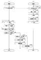
- FIG. 2 shows a flowchart of the identification processing and the identification information generation processing of this embodiment.
- the identification process is a process of identifying each of the battery modules M1 to M3 using the identification information ID generated by the identification information generation process, and is performed by the control unit 10.
- 2A is a flowchart showing the identification processing by the control unit 10
- FIG. 2B is a flowchart showing the identification information generation processing by the monitoring unit 30.
- the control unit 10 and the monitoring unit 30 perform each process when the vehicle is started, that is, when the ignition switch of the vehicle is turned on.
- step S30 it is determined whether the data transmission command is acquired from the control unit 10.
- step S30 If negative determination is made in step S30, step S30 is repeated. On the other hand, if an affirmative determination is made in step S30, the cell voltage data VD is acquired in step S32.
- step S34 an input process for acquiring the temperature data TDA1 to TDA3 is performed based on the voltage signals input from the temperature sensors THA1 to THA3. In the present embodiment, the process of step S34 corresponds to the "input processing unit".
- step S34 the monitoring unit 30 sends the voltage signals of the temperature sensors THA1 to THA3 to the terminals connected to the temperature sensors THA1 to THA3 among the plurality of terminals CH1 to CH4 of the connector 34 in the predetermined voltage range HV (see FIG. Input processing is performed in (4). Specifically, the monitoring unit 30 converts the voltage signal, which is an analog signal corresponding to the temperature of the assembled battery 22, into temperature data TDA1 to TDA3, which are digital signals indicating voltage values within the predetermined voltage range HV.
- the predetermined voltage range HV is, for example, a voltage range of 0.5V to 4.5V.
- the voltage signal is not input to the empty terminals, and the voltage of the empty terminals is set to a constant voltage such as the ground voltage.
- the monitoring unit 30 sets the voltage of the empty terminal to a voltage outside the predetermined voltage range HV.
- the monitoring unit 30 generates out-of-range data ND, which is a digital signal indicating a voltage value outside the predetermined voltage range HV, as the voltage of the vacant terminal.
- the voltage value of the out-of-range data ND is, for example, 0V.
- step S36 the identification information ID is generated. Specifically, the identification information ID in which the data input in step S34 are arranged in the order of the terminals CH1 to CH4 of the connector 34 is generated. Therefore, the identification information ID is composed of three pieces of temperature data TDA1 to TDA3 and one piece of out-of-range data ND.
- the empty terminals are set to be different for each of the battery modules M1 to M3, and the order of the temperature data TDA1 to TDA3 and the out-of-range data ND is different for each of the battery modules M1 to M3. Therefore, different identification information ID is generated for each of the battery modules M1 to M3.
- the process of step S36 corresponds to a "generation unit.”
- step S38 the data including the cell voltage data VD and the identification information ID is transmitted to the control unit 10, and the identification information generation process ends.
- step S12 it is determined whether or not data is acquired from the monitoring unit 30 of each of the battery modules M1 to M3.
- the process of step S12 corresponds to the “identification information acquisition unit”.
- step S12 If a negative decision is made in step S12, step S12 is repeated. On the other hand, if an affirmative decision is made in step S12, then in step S14 the battery modules M1 to M3 for which data was obtained in step S12 are identified. In addition, in this embodiment, the process of step S14 corresponds to an "identification part.”
- step S14 the control unit 10 uses the map MP (see FIG. 3) stored in the storage unit 14 (see FIG. 1) of the control unit 10 to determine the identification information ID included in the data acquired in step S12. Based on this, the battery modules M1 to M3 are identified.
- the storage unit 14 is composed of, for example, a ROM, a rewritable nonvolatile memory, or the like.
- the map MP is correspondence information in which the battery modules M1 to M3 and the identification information ID are associated with each other. Identification information IDs for all the battery modules M1 to M3 included in the battery system 100 are stored in the map MP in association with the battery modules M1 to M3. In the present embodiment, the identification information ID stored in the map MP is limited to the identification information ID corresponding to the battery modules M1 to M3 included in the battery system 100.
- step S16 it is determined whether data has been acquired from the monitoring units 30 of all the battery modules M1 to M3.
- step S16 it is determined whether data has been acquired from the monitoring units 30 of all the battery modules M1 to M3.
- step S18 it is determined in step S18 whether all the battery modules M1 to M3 have been identified.
- step S18 If the affirmative decision is made in step S18, the identification process is ended.
- step S20 it is determined in step S20 whether the number of non-identification modules is one.
- the reason for the presence of the non-identification module is that the inaccurate identification information ID is acquired due to the malfunction of the monitoring unit 30, and the identification information ID stored in the map MP is due to the malfunction of the temperature sensors THA1 to THA3. It includes that the identification information ID different from is acquired.
- the identification abnormality is an abnormality in which all the battery modules M1 to M3 cannot be identified.
- the control unit 10 cannot properly acquire the voltage and temperature of the assembled battery 22 of each battery module M1 to M3, and cannot appropriately control each battery module M1 to M3. Therefore, when the identification abnormality occurs, the vehicle is not normally started.
- a method of notifying the occurrence of the identification abnormality there is a method of generating an alarm sound or displaying the abnormality on the display of the car navigation device.
- the non-identification module is identified by the elimination method in step S24. Specifically, the non-identification module is identified as the battery modules M1 to M3 associated with the identification information ID not used to identify the battery modules M1 to M3 in the map MP.
- the replacement request is a request for urging replacement of the non-identification module.
- the control unit 10 can identify all the battery modules M1 to M3, although the non-identification module is present, and appropriately obtains the voltage and temperature of the assembled battery 22 of each battery module M1 to M3. it can. Therefore, when a replacement request is made, the vehicle is normally started. By notifying the generation of the replacement request, the driver can be prompted to replace the non-identification module, and the occurrence of the identification abnormality can be suppressed.
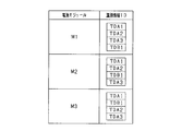
- FIG. 3 shows the map MP.
- the temperature sensor THA1 in the battery module M1, the temperature sensor THA1 is connected to the terminal CH1 of the connector 34, the temperature sensor THA2 is connected to the terminal CH2, and the temperature sensor THA3 is connected to the terminal CH3. It is connected to the. Therefore, as shown in FIG. 3, in the map MP, information in which the temperature data TDA1, the temperature data TDA2, the temperature data TDA3, and the out-of-range data ND are consecutive in this order is stored as the identification information ID corresponding to the battery module M1. ing.
- the temperature sensor THA1 is connected to the terminal CH1 of the connector 34, the temperature sensor THA2 is connected to the terminal CH2, and the temperature sensor THA3 is connected to the terminal CH4. Therefore, in the map MP, information in which the temperature data TDA1, the temperature data TDA2, the out-of-range data ND, and the temperature data TDA3 are consecutive in this order is stored as the identification information ID corresponding to the battery module M2.
- the temperature sensor THA1 is connected to the terminal CH1 of the connector 34, the temperature sensor THA2 is connected to the terminal CH3, and the temperature sensor THA3 is connected to the terminal CH4. Therefore, in the map MP, information in which the temperature data TDA1, the out-of-range data ND, the temperature data TDA2, and the temperature data TDA3 are consecutive in this order is stored as the identification information ID corresponding to the battery module M3.
- the control unit 10 acquires data from a certain monitoring unit 30, the identification information ID included in the data is the temperature data TDA1, the temperature data TDA2, the temperature data TDA3, and the out-of-range data ND in this order. It is assumed that the information is continuous. In this case, the control unit 10 can identify the battery module whose data has been acquired as the battery module M1.
- the control unit 10 divides the acquired identification information ID into four voltage value data indicating a voltage value, and the voltage value indicated by each voltage value data is included in the predetermined voltage range HV. To determine. When the voltage value indicated by the voltage value data is within the predetermined voltage range HV, the control unit 10 determines that the voltage value data is the temperature data TDA1 to TDA3. When the voltage value indicated by the voltage value data is not included in the predetermined voltage range HV, the voltage value data is determined to be the out-of-range data ND. When the voltage value data is the temperature data TDA1 to TDA3, the voltage value indicated by the voltage value data is included in the predetermined voltage range HV regardless of the temperature of the battery pack 22. Therefore, the control unit 10 can determine whether the voltage value data is the temperature data TDA1 to TDA3, regardless of the temperature of the battery pack 22.
- the temperature data TDA1 to TDA3 included in the identification information ID are used to obtain the temperature of the assembled battery 22. That is, in the present embodiment, the temperature data TDA1 to TDA3 serve as both data for identifying the battery module M1 and data for obtaining the temperature of the assembled battery 22. Therefore, it is not necessary to generate the data for identifying the battery module M1 separately from the data for acquiring the temperature of the assembled battery 22.
- FIG. 4 shows the temperature characteristics of the temperature data TDA1 to TDA3 and the out-of-range data ND.
- a predetermined temperature range HT is predetermined as a temperature range in which the assembled battery 22 can operate.
- the monitoring unit 30 inputs the voltage signals of the temperature sensors THA1 to THA3 within the predetermined voltage range HV and determines the voltage value within the predetermined voltage range HV.
- the temperature data TDA1 to TDA3 shown are generated. Specifically, the input processing is performed so that the voltage linearly changes in the predetermined voltage range HV in response to the temperature change of the assembled battery 22 in the predetermined temperature range HT.
- the input process is performed so that the temperature characteristic has the inverse characteristic of decreasing.
- the predetermined temperature range HT includes an outside air temperature range HG and a high temperature range HK.
- the outside air temperature range HG is a temperature range corresponding to the outside air temperature, and generally, the vehicle is started in this outside air temperature range HG.
- the high temperature range HK is a temperature range on the higher temperature side than the outside air temperature range HG.
- the input signals are processed so that the voltage signals of the temperature sensors THA1 to THA3 have the inverse temperature characteristics, so that the voltage corresponding to the outside air temperature range HG in the predetermined voltage range HV. Becomes higher than the voltage corresponding to the high temperature range HK.
- the voltage outside the predetermined voltage range HV generated at the vacant terminal is set to a voltage on the lower voltage side than the predetermined voltage range HV corresponding to the inverse temperature characteristic, and the voltage is lower than the predetermined voltage range HV.
- the out-of-range data ND indicating the value is generated. Therefore, as shown in FIG. 4, in the outside air temperature range HG, the voltage value difference between the temperature data TDA1 to TDA3 and the out-of-range data ND can be made relatively large. As a result, the temperature data TDA1 to TDA3 and the out-of-range data ND can be easily determined, and the identification information ID can be properly identified.
- each of the battery modules M1 to M3 includes a monitoring unit 30 and temperature sensors THA1 to THA3 electrically connected to the monitoring unit 30, and the monitoring unit 30 includes the temperature sensors THA1 to THA1. Based on the electrical signal input from THA3, different identification information ID is generated for each of the battery modules M1 to M3. Since the monitoring unit 30 can generate the identification information ID based on the electric signals input from the temperature sensors THA1 to THA3, the identification information ID does not need to be set inside. As a result, the monitoring unit 30 can be shared by the plurality of battery modules M1 to M3 forming the battery system 100.
- the temperature sensors THA1 to THA3 and the terminals CH1 to CH4 of the connector 34 are connected so that the empty terminals of the connector 34 are different for each of the battery modules M1 to M3.
- the input signals are different between the terminals connected to the temperature sensors THA1 to THA3 and the empty terminals. Therefore, by connecting the empty terminals differently for each of the battery modules M1 to M3, the signals input to the terminals CH1 to CH4 of the connector 34 can be made different for each of the battery modules M1 to M3.
- the identification information ID can be generated based on the signal of.
- the voltage signals input to the terminals connected to the temperature sensors THA1 to THA3 are input processed in the predetermined voltage range HV, and the voltage of the empty terminal is , Outside the predetermined voltage range HV. Therefore, an empty terminal can be specified from the input-processed data, and the battery modules M1 to M3 can be identified by using the information about the specified empty terminal as the identification information ID.
- the identification information ID itself be properly identified. Since the identification information ID is composed of the temperature data TDA1 to TDA3 and the out-of-range data ND, it is necessary to appropriately determine the temperature data TDA1 to TDA3 and the out-of-range data ND. Generally, the vehicle is activated in the outside air temperature range HG, and the identification information ID is generated in the outside air temperature range HG. Therefore, it is desired to appropriately determine the temperature data TDA1 to TDA3 and the out-of-range data ND in the outside air temperature range HG.
- the voltage outside the predetermined voltage range HV that is, the voltage value indicated by the out-of-range data ND is set according to the magnitude relationship between the voltage corresponding to the outside air temperature range HG and the voltage corresponding to the high temperature range HK.
- the voltage outside the predetermined voltage range HV is set to the voltage on the lower voltage side than the predetermined voltage range HV. ..
- the difference between the voltage values indicated by the temperature data TDA1 to TDA3 and the outside range data ND can be increased.
- the temperature data TDA1 to TDA3 and the out-of-range data ND can be appropriately determined, and the identification accuracy of the battery modules M1 to M3 based on the identification information ID can be improved.
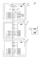
- the present embodiment differs from the first embodiment in that the cell module 20 includes a temperature sensor THB1.
- the temperature sensors THA1 to THA3 are referred to as first sensors THA1 to THA3, and the temperature sensor THB1 is referred to as a second sensor THB1.
- the first sensor THA1 to THA3 and the second sensor THB1 have different voltage levels of the voltage signal output according to the temperature of the battery pack 22. Therefore, even if the temperature of the battery pack 22 is the same between the first temperature data TDA1 to TDA3 of the first sensors THA1 to THA3 to which these voltage signals are input and the second temperature data TDB1 of the second sensor THB1, The voltage value indicated by the temperature data is different.
- FIG. 6 shows the temperature characteristics of the first temperature data TDA1 to TDA3 and the second temperature data TDB1. As shown in FIG. 6, the first temperature data TDA1 to TDA3 and the second temperature data TDB1 have the same output increase/decrease characteristic with respect to the temperature of the assembled battery 22, that is, the increase/decrease characteristic of the voltage value indicated by the temperature data.
- the voltage value indicated by the first temperature data TDA1 to TDA3 is offset to the high voltage side with respect to the voltage value indicated by the second temperature data TDB1. Therefore, the second voltage range HVB that is the voltage range of the second temperature data TDB1 is offset to the high voltage side with respect to the first voltage range HVA that is the voltage range of the first temperature data TDA1 to TDA3.
- the first voltage range HVA is a voltage range of 0.5V to 4.0V
- the second voltage range HVB is a voltage range of 1.0V to 4.5V
- the offset is 0.5V, for example. is there.
- the present embodiment is different from the first embodiment in that there is no empty terminal in the connector 34.
- the connection patterns of the first sensors THA1 to THA3 and the second sensor THB1 with respect to the terminals CH1 to CH4 of the connector 34 are connected differently for each of the battery modules M1 to M3.
- the terminals to which THB1 is connected are set to be different for each of the battery modules M1 to M3.
- FIG. 7 shows the map MP of this embodiment.
- the first sensor THA1 is connected to the terminal CH1 of the connector 34
- the first sensor THA2 is connected to the terminal CH2
- the first sensor THA3. Is connected to the terminal CH3, and the second sensor THB1 is connected to the terminal CH4. Therefore, as shown in FIG. 7, in the map MP, information in which the first temperature data TDA1, the first temperature data TDA2, the first temperature data TDA3, and the second temperature data TDB1 are consecutive in this order corresponds to the battery module M1. Is stored as the identification information ID.
- the first sensor THA1 is connected to the terminal CH1 of the connector 34
- the first sensor THA2 is connected to the terminal CH2
- the second sensor THB1 is connected to the terminal CH3.
- the first sensor THA3 is connected to the terminal CH4. Therefore, in the map MP, information in which the first temperature data TDA1, the first temperature data TDA2, the second temperature data TDB1, and the first temperature data TDA3 are consecutive in this order is stored as the identification information ID corresponding to the battery module M2. ing.
- the first sensor THA1 is connected to the terminal CH1 of the connector 34
- the second sensor THB1 is connected to the terminal CH2
- the first sensor THA2 is connected to the terminal CH3.
- One sensor THA3 is connected to the terminal CH4. Therefore, in the map MP, information in which the first temperature data TDA1, the second temperature data TDB1, the first temperature data TDA2, and the first temperature data TDA3 are consecutive in this order is stored as the identification information ID corresponding to the battery module M3. ing.
- the control unit 10 obtains data from a certain monitoring unit 30, the identification information ID included in the data has the first temperature data TDA1, the first temperature data TDA2, the first temperature data TDA3, and the first temperature data TDA3. It is assumed that the 2 temperature data TDB1 is information continuous in this order. In this case, the control unit 10 identifies the battery module whose data has been acquired as the battery module M1.
- the control unit 10 divides the acquired identification information ID into four voltage value data indicating a voltage value, and selects the voltage value data indicating the largest voltage value among the four voltage value data. select.
- the control unit 10 determines the selected voltage value data as the second temperature data TDB1 and determines the other voltage value data as the first temperature data TDA1 to TDA3.
- the first temperature data TDA1 to TDA3 and the second temperature data TDB1 can be determined, and the identification information ID composed of these temperature data TDA1 to TDA3 and TDB1 is used to determine the battery modules M1 to M3. Can be identified.
- the temperature sensors THA1 to THA3 and THB1 are connected to the terminals CH1 to CH4 of the connector 34 so that the terminals to which the second sensor THB1 is connected are different for each of the battery modules M1 to M3.
- the terminal connected to the first sensor THA1 to THA3 and the terminal connected to the second sensor THB1 have different voltage levels of the voltage signal. Therefore, by connecting the electric wiring 36 so that the terminal to which the second sensor THB1 is connected is different for each electric module, the signals input to the terminals CH1 to CH4 of the connector 34 are supplied to the battery modules M1 to M3, respectively.
- the identification information ID can be generated based on this signal.
- the first temperature data TDA1 to TDA3 and the second temperature data TDB1 have the same output increase/decrease characteristics with respect to the temperature of the battery pack 22, and the first temperature data does not depend on the temperature of the battery pack 22.
- the difference between the voltage values indicated by TDA1 to TDA3 and the second temperature data TDB1, that is, the offset is maintained constant.
- the temperature data TDA1 to TDA3 and the out-of-range data ND can be determined with a constant accuracy regardless of the temperature of the assembled battery 22, and the identification accuracy of the battery modules M1 to M3 based on the identification information ID can be improved. it can.
- the present embodiment differs from the first embodiment in that the cell module 20 includes a power supply unit 26 that supplies power to the monitoring unit 30 using the power of the assembled battery 22.
- the power supply unit 26 corresponds to an “external member”.
- a power connector 40 is provided in the monitoring unit 30.
- the power supply connector 40 has three power supply terminals CH11 to CH13 connectable to the power supply unit 26.
- the power supply connector 40 is connected to a power supply line 42 extending from the power supply unit 26, whereby the monitoring unit 30 is connected. Power is supplied.
- the power supply line 42 is connected to one of the power supply terminals CH11 to CH13.
- the power supply terminals CH11 to CH13 to which the power supply line 42 is connected are set to be different for each of the battery modules M1 to M3. Therefore, each of the battery modules M1 to M3 can be identified by using the power supply terminals CH11 to CH13 to which the power supply line 42 is connected as the identification information ID.
- each of the battery modules M1 to M3 includes the monitoring unit 30 and the power supply unit 26 electrically connected to the monitoring unit 30, and the monitoring unit 30 is a power source. Based on the electric power supplied from the unit 26, different identification information ID is generated for each of the battery modules M1 to M3. Since the monitoring unit 30 can generate the identification information ID based on the power supplied from the power supply unit 26, the identification information ID does not need to be set inside. As a result, the monitoring unit 30 can be shared by the plurality of battery modules M1 to M3 forming the battery system 100.
- the number of battery modules is not limited to three, and may be two or four or more.
- the external member may be a resistor connected to the monitoring unit 30.
- This resistance may be an internal resistance connected to the monitoring unit 30 inside the battery modules M1 to M3 or an internal resistance connected to the monitoring unit 30 outside the battery modules M1 to M3. ..
- the temperature characteristics of the temperature data TDA1 to TDA3 are inverse characteristics in which the voltage decreases in accordance with the temperature increase, but the present invention is not limited to this.
- the positive characteristic may be such that the voltage rises in response to the temperature rise.
- the voltage corresponding to the outside air temperature range HG is lower than the voltage corresponding to the high temperature range HK in the predetermined voltage range HV.
- the voltage outside the predetermined voltage range HV generated at the vacant terminal is set to a voltage higher than the predetermined voltage range HV corresponding to the temperature characteristic of the positive characteristic, and a voltage value higher than the predetermined voltage range HV is set.
- the out-of-range data ND shown is generated. You may.
- a voltage value higher than the predetermined voltage range HV is 5.0V, for example.
- the number of temperature sensors is not limited to three, and the number of terminals of the connector 34 is not limited to four. Therefore, the number of empty terminals of the connector 34 is not limited to one, and may be two or more.
- the connection patterns of the first sensors THA1 and THA2 and the second sensor THB1 to the terminals CH1 to CH4 of the connector 34 may be connected differently for each of the battery modules M1 to M3. Accordingly, the connection pattern of each battery module M1 to M3 is set such that the combination of the empty terminal and the terminal to which the second sensor THB1 is connected differs for each battery module M1 to M3.
- the present invention is not limited to this. It may be carried out at the time of assembling the vehicle, or may be carried out at every predetermined measurement cycle.
- the present invention is not limited to this.
- the voltage may change non-linearly, for example, exponentially with respect to temperature change.
- control unit 10 and the monitoring unit 30 are not connected by a communication line, and the control unit 10 acquires the identification information ID and the like from the monitoring unit 30 by wireless communication.
- the control unit 10 and the monitoring unit 30 may be connected by a communication line, and the control unit 10 may acquire the identification information ID and the like from the monitoring unit 30 by wired communication.
- the identification information ID can be generated based on the order of connection of the monitoring units 30, but instead of the external The identification information ID may be generated based on the electric signal input from the member.
Landscapes
- Engineering & Computer Science (AREA)
- Chemical & Material Sciences (AREA)
- Chemical Kinetics & Catalysis (AREA)
- Electrochemistry (AREA)
- General Chemical & Material Sciences (AREA)
- Manufacturing & Machinery (AREA)
- Power Engineering (AREA)
- General Physics & Mathematics (AREA)
- Physics & Mathematics (AREA)
- Microelectronics & Electronic Packaging (AREA)
- Secondary Cells (AREA)
- Charge And Discharge Circuits For Batteries Or The Like (AREA)
- Tests Of Electric Status Of Batteries (AREA)
Priority Applications (2)
| Application Number | Priority Date | Filing Date | Title |
|---|---|---|---|
| US17/339,265 US11876193B2 (en) | 2018-12-04 | 2021-06-04 | Battery system |
| US18/521,300 US20240097219A1 (en) | 2018-12-04 | 2023-11-28 | Battery system |
Applications Claiming Priority (2)
| Application Number | Priority Date | Filing Date | Title |
|---|---|---|---|
| JP2018227544A JP6935793B2 (ja) | 2018-12-04 | 2018-12-04 | 電池システム |
| JP2018-227544 | 2018-12-04 |
Related Child Applications (1)
| Application Number | Title | Priority Date | Filing Date |
|---|---|---|---|
| US17/339,265 Continuation US11876193B2 (en) | 2018-12-04 | 2021-06-04 | Battery system |
Publications (1)
| Publication Number | Publication Date |
|---|---|
| WO2020116312A1 true WO2020116312A1 (ja) | 2020-06-11 |
Family
ID=70974196
Family Applications (1)
| Application Number | Title | Priority Date | Filing Date |
|---|---|---|---|
| PCT/JP2019/046587 Ceased WO2020116312A1 (ja) | 2018-12-04 | 2019-11-28 | 電池システム |
Country Status (3)
| Country | Link |
|---|---|
| US (2) | US11876193B2 (enExample) |
| JP (3) | JP6935793B2 (enExample) |
| WO (1) | WO2020116312A1 (enExample) |
Cited By (2)
| Publication number | Priority date | Publication date | Assignee | Title |
|---|---|---|---|---|
| EP4242677A1 (en) | 2022-03-07 | 2023-09-13 | MediaTek Inc. | Universal gauge master solution at multi-battery system |
| JP2024510284A (ja) * | 2021-08-30 | 2024-03-06 | エルジー エナジー ソリューション リミテッド | 電池管理装置およびその動作方法 |
Families Citing this family (12)
| Publication number | Priority date | Publication date | Assignee | Title |
|---|---|---|---|---|
| FR2650156A1 (fr) | 1989-07-26 | 1991-02-01 | Bizet Andre | Liquide thanatopraxique |
| JP7099339B2 (ja) * | 2019-01-18 | 2022-07-12 | 株式会社デンソー | 電池システム |
| US12189751B2 (en) | 2020-01-23 | 2025-01-07 | Panasonic Intellectual Property Management Co., Ltd. | Power storage pack authentication method, power storage pack, charging device, electric mobile body, and electric mobile body control device |
| CN113270649B (zh) * | 2020-02-17 | 2024-01-30 | 丰田自动车株式会社 | 电池控制装置、电池控制方法、存储介质和车辆 |
| CN114597985A (zh) | 2020-12-03 | 2022-06-07 | 麦太保有限公司 | 蓄电池包、蓄电池驱动式设备、外部充电器和配置方法 |
| KR102667059B1 (ko) | 2021-08-31 | 2024-05-20 | 컨템포러리 엠퍼렉스 테크놀로지 씨오., 리미티드 | 차량 배터리 교체 방법,배터리 교체 스테이션,차량 및 시스템 |
| JP7561204B2 (ja) * | 2021-12-24 | 2024-10-03 | 香港時代新能源科技有限公司 | 電池管理システムと給電機器 |
| CN116461376A (zh) | 2022-01-07 | 2023-07-21 | 宁德时代新能源科技股份有限公司 | 换电验证方法、装置、电子设备、换电站及车辆 |
| JP7473661B2 (ja) | 2022-01-07 | 2024-04-23 | 寧徳時代新能源科技股▲分▼有限公司 | バッテリ交換検証方法、装置、電子機器、バッテリ交換ステーション及び電力使用装置 |
| KR20230134338A (ko) | 2022-03-14 | 2023-09-21 | 에스케이온 주식회사 | 온도 센서를 포함하는 엔드 플레이트 어셈블리, 이를 포함하는 배터리 모듈 및 배터리 팩 |
| JP2024041503A (ja) | 2022-09-14 | 2024-03-27 | カワサキモータース株式会社 | バッテリ管理方法、記憶制御装置、移動体、およびサーバ |
| CN118432224A (zh) * | 2024-04-28 | 2024-08-02 | 重庆博与精供应链管理有限公司 | 一种家庭光伏储能站中电池位置识别绑定及解绑的方法 |
Citations (2)
| Publication number | Priority date | Publication date | Assignee | Title |
|---|---|---|---|---|
| JP2006172303A (ja) * | 2004-12-17 | 2006-06-29 | Ricoh Co Ltd | Idタグ用リーダ及び/又はライタ |
| JP2013524766A (ja) * | 2010-04-16 | 2013-06-17 | エルジー・ケム・リミテッド | バッテリー管理システム及びバッテリー管理システム内におけるデータ伝送方法 |
Family Cites Families (12)
| Publication number | Priority date | Publication date | Assignee | Title |
|---|---|---|---|---|
| JP3893291B2 (ja) | 2002-01-10 | 2007-03-14 | パナソニック・イーブイ・エナジー株式会社 | ハイブリッド車用電池電源装置 |
| EP2183835A2 (en) * | 2007-03-26 | 2010-05-12 | The Gillette Company | Ultra fast battery charger with battery sensing |
| JP5194891B2 (ja) | 2008-03-05 | 2013-05-08 | トヨタ自動車株式会社 | 電動車両の電源制御装置 |
| JP5084647B2 (ja) | 2008-07-14 | 2012-11-28 | 三洋電機株式会社 | 電池装置 |
| US9762069B2 (en) * | 2009-05-19 | 2017-09-12 | Duracell U.S. Operations, Inc. | Multi-use fast rate charging stand |
| WO2013014758A1 (ja) | 2011-07-27 | 2013-01-31 | 株式会社日立製作所 | 電池システム |
| EP2765643B1 (en) | 2011-10-07 | 2016-09-14 | Hitachi Automotive Systems, Ltd. | Controller and battery monitoring system |
| JP5978755B2 (ja) | 2012-05-17 | 2016-08-24 | 三菱自動車工業株式会社 | 電源管理装置 |
| US10063072B2 (en) * | 2013-11-29 | 2018-08-28 | Hitachi Automotive Systems, Ltd. | Battery module and assembled battery |
| JP6524274B2 (ja) * | 2017-05-26 | 2019-06-05 | ローム株式会社 | 信号灯モニタ |
| JP7036605B2 (ja) * | 2018-01-30 | 2022-03-15 | プライムアースEvエナジー株式会社 | 組電池の状態推定装置及び組電池の状態推定方法 |
| WO2019230069A1 (ja) * | 2018-06-01 | 2019-12-05 | 住友電気工業株式会社 | 電池管理装置、電池情報処理システム、及び電池情報処理方法 |
-
2018
- 2018-12-04 JP JP2018227544A patent/JP6935793B2/ja active Active
-
2019
- 2019-11-28 WO PCT/JP2019/046587 patent/WO2020116312A1/ja not_active Ceased
-
2021
- 2021-06-04 US US17/339,265 patent/US11876193B2/en active Active
- 2021-08-25 JP JP2021137399A patent/JP7251580B2/ja active Active
-
2023
- 2023-03-21 JP JP2023044813A patent/JP7655339B2/ja active Active
- 2023-11-28 US US18/521,300 patent/US20240097219A1/en active Pending
Patent Citations (2)
| Publication number | Priority date | Publication date | Assignee | Title |
|---|---|---|---|---|
| JP2006172303A (ja) * | 2004-12-17 | 2006-06-29 | Ricoh Co Ltd | Idタグ用リーダ及び/又はライタ |
| JP2013524766A (ja) * | 2010-04-16 | 2013-06-17 | エルジー・ケム・リミテッド | バッテリー管理システム及びバッテリー管理システム内におけるデータ伝送方法 |
Cited By (2)
| Publication number | Priority date | Publication date | Assignee | Title |
|---|---|---|---|---|
| JP2024510284A (ja) * | 2021-08-30 | 2024-03-06 | エルジー エナジー ソリューション リミテッド | 電池管理装置およびその動作方法 |
| EP4242677A1 (en) | 2022-03-07 | 2023-09-13 | MediaTek Inc. | Universal gauge master solution at multi-battery system |
Also Published As
| Publication number | Publication date |
|---|---|
| US20240097219A1 (en) | 2024-03-21 |
| US20210296714A1 (en) | 2021-09-23 |
| JP7655339B2 (ja) | 2025-04-02 |
| JP2021185580A (ja) | 2021-12-09 |
| JP2023080115A (ja) | 2023-06-08 |
| JP2020091978A (ja) | 2020-06-11 |
| JP6935793B2 (ja) | 2021-09-15 |
| US11876193B2 (en) | 2024-01-16 |
| JP7251580B2 (ja) | 2023-04-04 |
Similar Documents
| Publication | Publication Date | Title |
|---|---|---|
| JP7251580B2 (ja) | 電池システム | |
| JP7028146B2 (ja) | 電池システム | |
| JP5928107B2 (ja) | センサーシステム、センサーモジュール | |
| EP2559135B1 (en) | Battery management system and method for transferring data within the battery management system | |
| JP2020091978A5 (enExample) | ||
| JP7416133B2 (ja) | 電池システム、監視装置及び監視部 | |
| US9426587B2 (en) | Electronics in a receiver-in-canal module | |
| KR102547282B1 (ko) | 배터리 충방전 시간에 기반하여 충전을 제어하는 장치 및 방법 | |
| JP2016010198A (ja) | 充電制御装置、バッテリパック及び充電器 | |
| US10330586B2 (en) | Corrosion monitor | |
| JP2011127947A (ja) | 故障診断装置 | |
| US10979061B2 (en) | Analog-digital conversion device | |
| JP2016071635A (ja) | Ecuの異常監視回路 | |
| JP2010022118A (ja) | 充電装置 | |
| JP6390682B2 (ja) | 充電システム | |
| CN110954149A (zh) | 用于校准传感器系统的方法 | |
| JP5791584B2 (ja) | 電圧監視システム、電圧監視装置、及び電圧監視方法 | |
| JP6880988B2 (ja) | 組電池監視集積回路装置 | |
| WO2023095411A1 (ja) | 電池監視システム、電池監視装置、および電池監視方法 | |
| WO2019012611A1 (ja) | 処理装置 | |
| JP2006256547A (ja) | 電子制御装置 | |
| JP5553432B2 (ja) | 負荷制御回路 | |
| JP6797065B2 (ja) | 車載用電子制御装置 | |
| JP2005345417A (ja) | 電子回路の故障判定回路 | |
| JP2009115597A (ja) | 温度センサの異常検出方法 |
Legal Events
| Date | Code | Title | Description |
|---|---|---|---|
| 121 | Ep: the epo has been informed by wipo that ep was designated in this application |
Ref document number: 19891904 Country of ref document: EP Kind code of ref document: A1 |
|
| NENP | Non-entry into the national phase |
Ref country code: DE |
|
| 122 | Ep: pct application non-entry in european phase |
Ref document number: 19891904 Country of ref document: EP Kind code of ref document: A1 |