WO2019230069A1 - 電池管理装置、電池情報処理システム、及び電池情報処理方法 - Google Patents
電池管理装置、電池情報処理システム、及び電池情報処理方法 Download PDFInfo
- Publication number
- WO2019230069A1 WO2019230069A1 PCT/JP2019/005906 JP2019005906W WO2019230069A1 WO 2019230069 A1 WO2019230069 A1 WO 2019230069A1 JP 2019005906 W JP2019005906 W JP 2019005906W WO 2019230069 A1 WO2019230069 A1 WO 2019230069A1
- Authority
- WO
- WIPO (PCT)
- Prior art keywords
- battery
- unit
- information
- recording
- vehicle
- Prior art date
Links
Images


Classifications
-
- H—ELECTRICITY
- H01—ELECTRIC ELEMENTS
- H01M—PROCESSES OR MEANS, e.g. BATTERIES, FOR THE DIRECT CONVERSION OF CHEMICAL ENERGY INTO ELECTRICAL ENERGY
- H01M10/00—Secondary cells; Manufacture thereof
- H01M10/42—Methods or arrangements for servicing or maintenance of secondary cells or secondary half-cells
- H01M10/425—Structural combination with electronic components, e.g. electronic circuits integrated to the outside of the casing
-
- H—ELECTRICITY
- H01—ELECTRIC ELEMENTS
- H01M—PROCESSES OR MEANS, e.g. BATTERIES, FOR THE DIRECT CONVERSION OF CHEMICAL ENERGY INTO ELECTRICAL ENERGY
- H01M10/00—Secondary cells; Manufacture thereof
- H01M10/42—Methods or arrangements for servicing or maintenance of secondary cells or secondary half-cells
- H01M10/48—Accumulators combined with arrangements for measuring, testing or indicating the condition of cells, e.g. the level or density of the electrolyte
- H01M10/482—Accumulators combined with arrangements for measuring, testing or indicating the condition of cells, e.g. the level or density of the electrolyte for several batteries or cells simultaneously or sequentially
-
- H—ELECTRICITY
- H02—GENERATION; CONVERSION OR DISTRIBUTION OF ELECTRIC POWER
- H02J—CIRCUIT ARRANGEMENTS OR SYSTEMS FOR SUPPLYING OR DISTRIBUTING ELECTRIC POWER; SYSTEMS FOR STORING ELECTRIC ENERGY
- H02J7/00—Circuit arrangements for charging or depolarising batteries or for supplying loads from batteries
- H02J7/0013—Circuit arrangements for charging or depolarising batteries or for supplying loads from batteries acting upon several batteries simultaneously or sequentially
-
- H—ELECTRICITY
- H02—GENERATION; CONVERSION OR DISTRIBUTION OF ELECTRIC POWER
- H02J—CIRCUIT ARRANGEMENTS OR SYSTEMS FOR SUPPLYING OR DISTRIBUTING ELECTRIC POWER; SYSTEMS FOR STORING ELECTRIC ENERGY
- H02J7/00—Circuit arrangements for charging or depolarising batteries or for supplying loads from batteries
- H02J7/0047—Circuit arrangements for charging or depolarising batteries or for supplying loads from batteries with monitoring or indicating devices or circuits
-
- B—PERFORMING OPERATIONS; TRANSPORTING
- B60—VEHICLES IN GENERAL
- B60L—PROPULSION OF ELECTRICALLY-PROPELLED VEHICLES; SUPPLYING ELECTRIC POWER FOR AUXILIARY EQUIPMENT OF ELECTRICALLY-PROPELLED VEHICLES; ELECTRODYNAMIC BRAKE SYSTEMS FOR VEHICLES IN GENERAL; MAGNETIC SUSPENSION OR LEVITATION FOR VEHICLES; MONITORING OPERATING VARIABLES OF ELECTRICALLY-PROPELLED VEHICLES; ELECTRIC SAFETY DEVICES FOR ELECTRICALLY-PROPELLED VEHICLES
- B60L58/00—Methods or circuit arrangements for monitoring or controlling batteries or fuel cells, specially adapted for electric vehicles
- B60L58/10—Methods or circuit arrangements for monitoring or controlling batteries or fuel cells, specially adapted for electric vehicles for monitoring or controlling batteries
- B60L58/12—Methods or circuit arrangements for monitoring or controlling batteries or fuel cells, specially adapted for electric vehicles for monitoring or controlling batteries responding to state of charge [SoC]
-
- B—PERFORMING OPERATIONS; TRANSPORTING
- B60—VEHICLES IN GENERAL
- B60L—PROPULSION OF ELECTRICALLY-PROPELLED VEHICLES; SUPPLYING ELECTRIC POWER FOR AUXILIARY EQUIPMENT OF ELECTRICALLY-PROPELLED VEHICLES; ELECTRODYNAMIC BRAKE SYSTEMS FOR VEHICLES IN GENERAL; MAGNETIC SUSPENSION OR LEVITATION FOR VEHICLES; MONITORING OPERATING VARIABLES OF ELECTRICALLY-PROPELLED VEHICLES; ELECTRIC SAFETY DEVICES FOR ELECTRICALLY-PROPELLED VEHICLES
- B60L58/00—Methods or circuit arrangements for monitoring or controlling batteries or fuel cells, specially adapted for electric vehicles
- B60L58/10—Methods or circuit arrangements for monitoring or controlling batteries or fuel cells, specially adapted for electric vehicles for monitoring or controlling batteries
- B60L58/16—Methods or circuit arrangements for monitoring or controlling batteries or fuel cells, specially adapted for electric vehicles for monitoring or controlling batteries responding to battery ageing, e.g. to the number of charging cycles or the state of health [SoH]
-
- B—PERFORMING OPERATIONS; TRANSPORTING
- B60—VEHICLES IN GENERAL
- B60L—PROPULSION OF ELECTRICALLY-PROPELLED VEHICLES; SUPPLYING ELECTRIC POWER FOR AUXILIARY EQUIPMENT OF ELECTRICALLY-PROPELLED VEHICLES; ELECTRODYNAMIC BRAKE SYSTEMS FOR VEHICLES IN GENERAL; MAGNETIC SUSPENSION OR LEVITATION FOR VEHICLES; MONITORING OPERATING VARIABLES OF ELECTRICALLY-PROPELLED VEHICLES; ELECTRIC SAFETY DEVICES FOR ELECTRICALLY-PROPELLED VEHICLES
- B60L58/00—Methods or circuit arrangements for monitoring or controlling batteries or fuel cells, specially adapted for electric vehicles
- B60L58/10—Methods or circuit arrangements for monitoring or controlling batteries or fuel cells, specially adapted for electric vehicles for monitoring or controlling batteries
- B60L58/18—Methods or circuit arrangements for monitoring or controlling batteries or fuel cells, specially adapted for electric vehicles for monitoring or controlling batteries of two or more battery modules
-
- H—ELECTRICITY
- H01—ELECTRIC ELEMENTS
- H01M—PROCESSES OR MEANS, e.g. BATTERIES, FOR THE DIRECT CONVERSION OF CHEMICAL ENERGY INTO ELECTRICAL ENERGY
- H01M10/00—Secondary cells; Manufacture thereof
- H01M10/42—Methods or arrangements for servicing or maintenance of secondary cells or secondary half-cells
- H01M10/425—Structural combination with electronic components, e.g. electronic circuits integrated to the outside of the casing
- H01M2010/4271—Battery management systems including electronic circuits, e.g. control of current or voltage to keep battery in healthy state, cell balancing
-
- H—ELECTRICITY
- H02—GENERATION; CONVERSION OR DISTRIBUTION OF ELECTRIC POWER
- H02J—CIRCUIT ARRANGEMENTS OR SYSTEMS FOR SUPPLYING OR DISTRIBUTING ELECTRIC POWER; SYSTEMS FOR STORING ELECTRIC ENERGY
- H02J7/00—Circuit arrangements for charging or depolarising batteries or for supplying loads from batteries
- H02J7/0047—Circuit arrangements for charging or depolarising batteries or for supplying loads from batteries with monitoring or indicating devices or circuits
- H02J7/0048—Detection of remaining charge capacity or state of charge [SOC]
-
- H—ELECTRICITY
- H02—GENERATION; CONVERSION OR DISTRIBUTION OF ELECTRIC POWER
- H02J—CIRCUIT ARRANGEMENTS OR SYSTEMS FOR SUPPLYING OR DISTRIBUTING ELECTRIC POWER; SYSTEMS FOR STORING ELECTRIC ENERGY
- H02J7/00—Circuit arrangements for charging or depolarising batteries or for supplying loads from batteries
- H02J7/0047—Circuit arrangements for charging or depolarising batteries or for supplying loads from batteries with monitoring or indicating devices or circuits
- H02J7/005—Detection of state of health [SOH]
-
- Y—GENERAL TAGGING OF NEW TECHNOLOGICAL DEVELOPMENTS; GENERAL TAGGING OF CROSS-SECTIONAL TECHNOLOGIES SPANNING OVER SEVERAL SECTIONS OF THE IPC; TECHNICAL SUBJECTS COVERED BY FORMER USPC CROSS-REFERENCE ART COLLECTIONS [XRACs] AND DIGESTS
- Y02—TECHNOLOGIES OR APPLICATIONS FOR MITIGATION OR ADAPTATION AGAINST CLIMATE CHANGE
- Y02E—REDUCTION OF GREENHOUSE GAS [GHG] EMISSIONS, RELATED TO ENERGY GENERATION, TRANSMISSION OR DISTRIBUTION
- Y02E60/00—Enabling technologies; Technologies with a potential or indirect contribution to GHG emissions mitigation
- Y02E60/10—Energy storage using batteries
-
- Y—GENERAL TAGGING OF NEW TECHNOLOGICAL DEVELOPMENTS; GENERAL TAGGING OF CROSS-SECTIONAL TECHNOLOGIES SPANNING OVER SEVERAL SECTIONS OF THE IPC; TECHNICAL SUBJECTS COVERED BY FORMER USPC CROSS-REFERENCE ART COLLECTIONS [XRACs] AND DIGESTS
- Y02—TECHNOLOGIES OR APPLICATIONS FOR MITIGATION OR ADAPTATION AGAINST CLIMATE CHANGE
- Y02T—CLIMATE CHANGE MITIGATION TECHNOLOGIES RELATED TO TRANSPORTATION
- Y02T10/00—Road transport of goods or passengers
- Y02T10/60—Other road transportation technologies with climate change mitigation effect
- Y02T10/70—Energy storage systems for electromobility, e.g. batteries
Definitions
- the present invention relates to a battery management device, a battery information processing system, and a battery information processing method.
- This application claims priority based on Japanese Patent Application No. 2018-106343 filed on June 1, 2018, and incorporates all the description content described in the above Japanese application.
- HEV and EV are equipped with secondary batteries.
- a secondary battery mounted on a vehicle is configured as an assembled battery by further combining a plurality of battery modules obtained by combining a plurality of battery cells.
- Each of the battery cell and the battery module has battery characteristics individually.
- a battery cell and a battery module having similar or equivalent battery characteristics are combined to be manufactured as one assembled battery. However, after repeated charge and discharge by use, the battery characteristics vary.
- a method has been proposed in which a reusable battery module is selected from an assembled battery whose period has elapsed from the start of use, and the assembled battery is reconfigured.
- Patent Document 1 discloses a method of measuring all battery characteristics such as a full charge capacity and a degree of deterioration for each battery module or battery cell included in an assembled battery and determining whether or not the battery can be reused.
- Non-Patent Document 1 discloses collecting assembled batteries, measuring and classifying the performance (full charge capacity, deterioration degree) of all battery modules of the collected assembled batteries, and reusing them.
- the collected battery modules are classified into those that are reused for driving HEVs and EVs, those that are reused for industrial vehicles such as forklifts, and those that are reused for backup power sources.
- the derivation method of the battery characteristics of the secondary battery is a method of calculating parameters of elements of an equivalent circuit, or a method as disclosed in Patent Document 2 to Patent Document 5. Has been proposed.
- the battery management device includes a calculation unit that calculates a battery characteristic of a secondary battery including a plurality of unit batteries for each unit battery, and a battery characteristic for each unit battery calculated by the calculation unit.
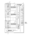
- FIG. 2 is a block diagram showing a configuration of a device mounted on a vehicle V.
- FIG. 3 is a perspective view illustrating a configuration example of a battery module device in Embodiment 1.
- FIG. It is a block diagram which shows the structural example of a battery management apparatus. 3 is a functional block diagram of a module control unit in the first embodiment.
- FIG. It is explanatory drawing which shows the equivalent circuit model of a unit battery (battery module or battery cell). It is explanatory drawing which shows the equivalent circuit model of a unit battery (battery module or battery cell). It is explanatory drawing which shows the equivalent circuit model of a unit battery (battery module or battery cell). It is explanatory drawing which shows the equivalent circuit model of a unit battery (battery module or battery cell).
- FIG. 6 is a block diagram illustrating a part of the configuration of an in-vehicle communication system according to Embodiment 2.
- FIG. 6 is a functional block diagram of a control unit of the battery monitoring apparatus in Embodiment 2.
- FIG. It is a flowchart which shows an example of the process sequence in a vehicle-mounted communication system.
- 5 is a diagram illustrating an outline of a secondary battery reuse system in Embodiment 3.
- FIG. FIG. 10 is a block diagram showing a part of the configuration of an in-vehicle communication system in a third embodiment. It is a block diagram of a server apparatus.
- FIG. 10 is a flowchart illustrating an example of a processing procedure of each device in the secondary battery reuse system according to the third embodiment. It is a figure which shows the outline
- FIG. 10 is a block diagram showing a part of the configuration of an in-vehicle communication system in a fourth embodiment. It is a figure which shows the outline
- This application aims at providing the battery management apparatus, battery information processing system, and battery information processing method which can contribute to the efficient use of resources, such as a rare earth contained in a secondary battery.
- the battery management device includes a calculation unit that calculates, for each unit battery, battery characteristics in a secondary battery including a plurality of unit batteries, and battery characteristics for each unit battery calculated by the calculation unit. Are recorded in association with unit battery identification information for identifying the unit battery and time information indicating the calculated time.
- the battery characteristics calculated based on voltage, current, or temperature in the unit battery (battery cell or battery module unit in which a plurality of battery cells are connected) included in the secondary battery are included in the device. It is recorded in association with information for identifying the unit battery and time information indicating the calculated time. Since the recorded battery characteristics can be read later, detailed battery characteristics can be obtained without requiring measurement during reuse or reproduction.
- each unit battery For each unit battery, record the battery characteristic history in association with the unit battery identification information, so that the history of many unit batteries can be collected and which unit batteries should be combined and reused quickly. Can be identified. The traceability of the unit battery can be improved and the reuse of each unit battery can be promoted. By reusing unit batteries as assembled batteries that have the same characteristics using the battery characteristics when they are actually used, it is possible to prevent rapid deterioration of each unit battery, that is, to efficiently use resources. Can be used.
- the said control part detects the arrival of the replacement
- the battery information processing system is a battery information processing system that processes information indicating characteristics of a secondary battery including a plurality of unit batteries, and is connected to the plurality of unit batteries.
- a plurality of battery management devices that calculate battery characteristics for each unit battery, and the battery characteristics calculated for each unit battery correspond to unit battery identification information that identifies the unit battery and time information that indicates the calculated time.
- a recording device for recording each unit battery.
- the recording device is not provided in the battery management device, but is provided in another device in a device (vehicle) that operates by receiving power supplied from the secondary battery. It may be provided by another external device.
- a device vehicle
- the recording device is easy to comprehensively specify the battery characteristics of a plurality of unit batteries or to make a determination in view of the state of the device (vehicle).
- the recording device is provided in a device different from a device that operates by receiving power from the secondary battery, and the battery management device displays the calculated battery characteristics in the unit battery identification information.
- a transmission unit for transmitting to the recording device in association with the time information and the recording device includes a reception unit for receiving the battery characteristics, and the received battery characteristics of each unit battery are the unit battery identification information and Records in association with time information.
- a recording device is provided outside the device, and the battery management device transmits the calculated battery characteristics in association with the time information to the recording device.
- a large number of battery characteristics of the secondary battery are recorded on the recording device.
- the battery characteristics include at least one of a unit battery full charge capacity, a charge rate, a deterioration degree, and a battery equivalent circuit parameter.
- the reading device that reads the recorded battery characteristic history for each unit battery. Before deterioration progresses, it is incorporated into a new secondary battery or reused for other purposes, thereby realizing efficient use of each secondary battery for each unit battery.
- the detection of the replacement time is performed not by the battery management device but by the reading device, so that comprehensive detection using other information such as information on the device itself provided with the secondary battery is also possible.
- the recording apparatus includes a plurality of processing nodes and a recording medium that perform operations for verifying and approving recording information for recording attribution of information based on an electronic signature obtained from private key information corresponding to a movement source.
- a distributed database network system configured to record the information by dispersing the calculation results in a plurality of recording media, connected to the battery management device, and calculating the battery characteristics calculated by the battery management device.
- the battery characteristics are recorded by a distributed database network system called a so-called block chain.
- a distributed database network system called a so-called block chain.
- the node is different for each unit battery, and creates the transaction by a signature using address information obtained based on secret key information.
- the battery characteristics are recorded using a signature using address information based on secret key information that is different for each unit battery, and from a node connected to the battery management device, in the distributed database network system. Realized by a transaction toward a specific node. Since the address information is given to each unit battery, it corresponds as unit battery identification information.
- the distributed database network system includes, for each unit battery, a node that processes a transaction for registering transfer using unit battery identification information.
- the battery characteristics calculated for each unit battery are associated with time information indicating the calculated time, recorded for each unit battery, and based on the recorded history of battery characteristics for each unit battery, The process which specifies a state for every unit battery is included.
- this application can not only be realized as a battery management apparatus provided with such a characteristic component.
- the battery information management method including the characteristic steps executed by the battery management device, and a program for causing a computer to execute these steps can also be realized.
- a battery module device including a unit battery instead of a single battery management device as a vehicle communication system including a communication device that transmits and receives information by communication with the battery module device, and further as a vehicle including the vehicle communication system It can also be realized. Realized as a semiconductor integrated circuit that realizes part or all of the components of the battery management device, a battery reuse system that uses information processed by the battery management device, and other systems that further include them can do.
- FIG. 1 is a diagram showing an outline of a secondary battery reuse system 100.
- the secondary battery reuse system 100 is a system that supports the reuse of the secondary battery 10 used in the vehicle V that is an EV or HEV.
- the secondary battery reuse system 100 makes it possible to sort out the battery modules 11 having the same battery characteristics from the used secondary batteries 10 and regenerate the secondary battery 10 by combining the sorted battery modules 11. .
- the battery module in which the output voltage at the time of discharging is still high and the deterioration has not progressed is reused for the secondary battery 10 for the vehicle V.
- the battery module 11 can be used in vehicles other than the vehicle V, for example, small vehicles such as forklifts and golf carts, and storage batteries used in backup power sources.
- Secondary battery 10 includes, for example, a lithium ion battery.
- the secondary battery 10 includes a plurality of battery modules (unit batteries) 11 in which a plurality of battery cells (unit batteries) 11a are connected in series or in series and parallel and accommodated in a casing.
- the secondary battery reuse system 100 of Embodiment 1 includes a plurality of battery management devices (see FIG. 2) that calculate battery characteristics for each of a plurality of unit batteries, and a recording device (see FIG. 4) that records the calculated battery characteristics.
- a battery information processing system including a module control unit 12a and a memory 12e).
- the battery characteristics of the battery module 11 of the secondary battery 10 mounted on the vehicle V by the battery information processing system are sequentially calculated and recorded.
- As a method for calculating battery characteristics it is desirable to use a highly accurate method that does not depend on uniform environment, such as a constant temperature. After the decision to reuse, the situation of having to measure for the first time at the time of disassembly is avoided, and if sufficient information is recorded, the measurement at the time of disassembly may be unnecessary.
- the battery characteristic calculation method will be described later.
- the battery characteristics calculated for each unit battery are recorded in association with information for identifying the unit battery so that it can be referred to later. This makes it unnecessary to determine whether or not the secondary battery 10 can be reused and to measure which unit battery should be combined. By referring to the record, it is possible to determine whether the secondary battery 10 is to be provided for a reuse product and which unit battery should be combined.
- FIG. 2 is a block diagram showing the configuration of the device mounted on the vehicle V. As shown in FIG. At least the battery module device 1 and the battery monitoring device 4 are mounted on the vehicle V with respect to the secondary battery 10.
- the power supply system using the secondary battery 10 in the vehicle V includes a relay, a generator (ALT), a starter motor, a battery, an electric load, a start switch, a charger and the like in addition to the battery module device 1. A detailed description of the power supply system is omitted.
- the battery module device 1 uses one battery management device (BMU) 12 in association with one battery module 11 constituting a part of the secondary battery 10.
- the battery management device 12 has an input / output unit 12d (see FIG. 4) and can exchange information with the battery monitoring device 4.
- the battery monitoring device 4 includes a control unit 40, a current detection unit 41, an input / output unit 43, a memory 44, a communication unit 45, and a power supply unit 46.
- the control unit 40 includes a processor such as a CPU (Central Processing Unit), a ROM (Read Only Memory), a RAM (Random Access Memory), a clock unit, a microcomputer having an input / output interface, a dedicated LSI (Large-Scale Integration), Alternatively, it is configured by FPGA (Field-Programmable Gate Array) or the like.
- the control unit 40 passes information through the input / output unit 43 for processing with the battery management device 12 that calculates information indicating the battery characteristics of the unit battery (battery module 11 or battery cell 11a).
- the current detection unit 41 is composed of, for example, a shunt resistor or a hall sensor for detecting the current of the secondary battery 10, and detects the charging current and the discharging current of the secondary battery 10 at a predetermined sampling period.
- the sampling period is, for example, 10 milliseconds, but is not limited thereto.
- the control unit 40 sequentially outputs the current value detected by the current detection unit 41 from the input / output unit 43 to each battery management device 12.
- the secondary battery 10 is configured by further connecting battery modules 11 in which battery cells 11 a are connected in series. Therefore, the current flowing through each unit battery (battery module 11 or battery cell 11a) can be detected by detecting the current at one end of the secondary battery 10 with one current detection unit 41.
- the current detection unit 41 may include a current detection circuit in each of the battery management devices 12 to be described later to detect the current.
- the input / output unit 43 is an input / output interface between the control unit 40 and the plurality of battery management devices 12, and is connected to a communication bus corresponding to the battery management device 12.
- the input / output unit 43 may be replaced with a wireless communication module, and may transmit / receive information to / from each battery management device 12 wirelessly.
- the memory 44 includes a nonvolatile memory such as a flash memory.
- the memory 44 stores management device identification information (BMU-ID) of each of the plurality of battery management devices 12 connected to the own device.
- the management device identification information may be stored in advance by setting, or the control unit 40 may collect management device identification information by inputting / outputting signals to / from each battery management device 12.
- the memory 44 may store unit battery identification information (MID: module ID / CID: cell ID) for identifying a unit battery (battery module 11 or battery cell 11a) of the secondary battery 10 for each unit battery.
- the communication unit 45 is a communication module that realizes communication corresponding to the in-vehicle LAN (Local Area Network).
- the communication unit 45 can transmit and receive information to and from other in-vehicle devices using, for example, CAN (Controller Area Network).
- the communication unit 45 may be a wireless communication module having a wireless communication antenna.
- the power supply unit 46 is a circuit that converts electric power from the secondary battery 10 into a predetermined voltage value and supplies it to each component unit.
- control unit 40 comprehensively specifies the state of the secondary battery 10 from the information obtained from the battery management device 12 of each battery module device 1, and detects an abnormality. Send / receive information to / from other devices.
- FIG. 3 is a perspective view illustrating a configuration example of the battery module device 1 according to the first embodiment.
- the battery module device 1 has a quadrangular prism shape as a whole.
- the battery module 11 is configured by stacking a plurality of battery cells 11a each having a plate shape in the thickness direction.
- Each battery cell 11a has a pair of electrode terminals 11b at both ends, and the plurality of electrode terminals 11b at each end are linearly arranged in the stacking direction.
- the battery module 11 is held by the holding member 1a.
- a substantially rectangular parallelepiped portion is formed extending to one end side in the stacking direction of the battery cells 11a, and a support plate 12g for supporting the battery management device 12 is provided on one surface side of the rectangular parallelepiped portion. .
- the battery management device 12 includes a circuit board 12h on which a circuit group (see FIG. 5) that performs processing is mounted.
- the circuit board 12h is substantially the same as the side surface on which the electrode terminals 11b of the battery cells 11a are arranged. Parallel to the support plate 12g.
- a connection terminal 12i is provided at an appropriate location on the circuit board 12h, on the battery cell 11a side.
- the electrode terminals 11b of the plurality of battery cells 11a are connected to the connection terminals 12i by conducting wires 12j.
- the conducting wire 12j is wired along the arrangement of the electrode terminals 11b arranged in the stacking direction, and once connected to one electrode terminal 11b of the battery cell 11a, the other end is connected to the connection terminal 12i.
- FIG. 4 is a block diagram illustrating a configuration example of the battery management device 12. As shown in FIG. 2, a plurality of battery management devices 12 are provided corresponding to each of the battery modules 11, but since all have the same configuration, only one battery management device 12 will be described.
- the battery management device 12 includes a module control unit 12a, a voltage detection circuit 12b, a temperature detection circuit 12c, an input / output unit 12d, a memory 12e, and a power supply circuit 12f that control the operation of the entire device mounted on the circuit board 12h.
- the voltage detection circuit 12b detects the voltage across the battery module 11 at a predetermined sampling period, and outputs information indicating the detection voltage to the module control unit 12a.
- the voltage detection circuit 12b may detect the voltage of each of the plurality of battery cells 11a included in the battery module 11.
- the sampling period is, for example, 10 milliseconds, but is not limited thereto.
- the temperature detection circuit 12c notifies the module controller 12a of the surface temperature of any one or a plurality of locations of the plurality of battery cells 11a in the battery module 11.
- the temperature detection circuit 12c uses a temperature sensor 120c configured by, for example, a thermistor, and reads the temperature based on the signal level of the output signal from the temperature sensor 120c.
- One temperature sensor 120c may be provided for each battery module 11, or one temperature sensor 120c may be provided for each battery cell 11a.
- the use of the thermistor is an example.
- a known temperature sensor such as a temperature sensor, a semiconductor temperature sensor, a thermocouple, or the like may be used.
- the temperature detection may be realized using a temperature sensor installed in any one or a plurality of battery modules 11.
- the battery monitoring device 4 reads the temperature from the output signal of the temperature sensor, and notifies each battery management device 12 via the input / output unit 12d.
- the input / output unit 12d is an input / output terminal between the battery monitoring device 4.
- the battery management device 12 transmits and receives signals (information) to and from the battery monitoring device 4 through the input / output unit 12d.
- the memory 12e is a non-volatile memory such as a flash memory.
- the management device identification information (BMU-ID) of its own device is stored in the non-rewritable area (Read Only) of the memory 12e.
- the memory 12e stores information generated by the process of the module control unit 12a.
- the power supply circuit 12 f is a circuit that converts the power supplied from the battery module 11 into a voltage suitable for driving each component of the battery management device 12 and supplies power to each component of the battery management device 12.
- the module control unit 12a is configured by a processor such as a CPU, a ROM, a RAM, a clock unit, a microcomputer having an input / output interface, a dedicated LSI, or an FPGA.
- a voltage detection circuit 12b, a temperature detection circuit 12c, an input / output unit 12d, and a memory 12e are connected to the input / output interface of the module control unit 12a.
- FIG. 5 is a functional block diagram of the module control unit 12a in the first embodiment.
- the module control unit 12a includes a control unit 121 that controls the entire apparatus, a timer 122, a recording unit 123, an input / output processing unit 124, a voltage acquisition unit 125, a current acquisition unit 126, a temperature acquisition unit 127, a current integration unit 128, a charging rate. It functions as a calculation unit 129, a parameter calculation unit 130, a full charge capacity calculation unit 131, and a deterioration degree calculation unit 132.
- the module control unit 12a controls each unit as the control unit 121, and calculates battery characteristics for each unit battery that is the battery module 11 or the battery cell 11a based on the detected voltage, temperature, and current.
- the module control unit 12a calculates, for example, a full charge capacity (FCC: Full Charge Capacity), a charge rate (SOC: State of Charge), a deterioration degree (SOH: State of Health), and an equivalent circuit parameter as battery characteristics.
- FCC Full Charge Capacity
- SOC State of Charge
- SOH State of Health
- the module control unit 12a functions as a timer 122 using a built-in timing unit.
- the timer 122 outputs the time measurement result to the control unit 121.
- the control unit 121 associates the time information based on the output from the timer 122 so as to store the calculated battery characteristics in time series.
- the module control unit 12a functions as the recording unit 123 using the memory 12e.
- the recording unit 123 records various types of information indicating battery characteristics calculated for each unit battery.
- Information for calculating the battery characteristics is stored in the memory 12e.
- information referred to for calculating a charging rate (SOC) for each unit battery is recorded.
- the memory 12e stores in advance a correlation between the open voltage (OCV: Open Circuit Voltage) of the unit battery (battery cell 11a or battery module 11 unit) and the charging rate.
- OCV Open Circuit Voltage
- the memory 12e stores unit battery identification information (MID) of the battery module 11 to be managed.
- the memory 12e may store unit battery identification information (CID) of each of the plurality of battery cells 11a constituting the battery module 11.
- the unit battery identification information (MID / CID) may be stored by the operation of the recording unit 123 via the specific device or the battery monitoring device 4 by the work operator. preferable.
- a storage medium storing unit battery identification information (MID / CID) is attached to each of the battery module 11 or the battery cell 11a, and the unit battery identification information is read from the storage medium and stored by the control unit 121. Also good.
- the memory 12e stores the initial full charge capacity or equivalent circuit parameter of each unit battery as information for calculating the degree of deterioration for each unit battery.
- This full charge capacity or equivalent circuit parameter may be stored in the order in which the unit batteries are connected and can be read out in a distinguishable manner.
- the memory 12e may store the relationship between the rate of increase in internal resistance and the discharge capacity ratio corresponding to the degree of deterioration as information for calculating the degree of deterioration for each unit battery. These new information may be stored by work by the above-described work operator.
- the module control unit 12a controls transmission / reception of information to / from the battery monitoring device 4 via the input / output unit 12d.
- the input / output processing unit 124 can transmit / receive information (FCC, SOC, SOH, or equivalent circuit parameter) indicating battery characteristics for each unit battery to and from the battery monitoring device 4.
- the module control unit 12a functions as a voltage acquisition unit 125, a current acquisition unit 126, and a temperature acquisition unit 127 that respectively acquire a voltage, a temperature, and a current used for calculating battery characteristics.
- the voltage acquisition part 125 acquires the information which shows the both-ends voltage of the battery module 11 output from the voltage detection circuit 12b, or the voltage of each battery cell 11a.
- the voltage acquisition unit 125 may acquire the both-ends voltage of the battery module 11 and the voltage in each of the battery cells 11a separately from each other.
- the current acquisition unit 126 acquires information indicating the current flowing through the battery module 11 or the battery cell 11a obtained from the battery monitoring device 4 through the input / output unit 12d as the current value of the unit battery.
- the temperature acquisition unit 127 acquires information indicating the temperature output from the temperature detection circuit 12c.
- the module control unit 12a integrates the current value acquired by the current acquisition unit 126 as the current integration unit 128.
- the integrated value of current is obtained by integrating the current with time, and corresponds to the amount of change in the charge amount.
- the integrated value of the current is positive in the case of charging and negative in the case of discharging.
- the integrated value in any given period can be positive or negative depending on the value of the charging current and discharging current in the period.
- the timing for starting the calculation of integration is the activation timing of the secondary battery 10, or the battery module device 1 or the battery monitoring device 4 itself.
- the integral value is calculated continuously. Note that the integrated value may be reset at a predetermined timing, for example, when the battery module 11 is recombined in the case of reuse.
- the module control unit 12a calculates the charge rate for each unit battery that is the battery module 11 or the battery cell 11a.
- the charging rate calculation unit 129 obtains an open circuit voltage in the unit battery that is the battery module 11 or the battery cell 11a.
- the charging rate calculation unit 129 estimates and calculates the charging rate by applying the obtained open circuit voltage to the correlation between the open circuit voltage stored in the recording unit 123 and the charging rate.
- the charge rate calculation unit 129 calculates the charge rate using the charge current and discharge current obtained by integration by the current integration unit 128 and the full charge capacity described later, based on the charge rate at a specific time. May be.
- the module control unit 12a calculates parameters of each element of the equivalent circuit for the unit battery.
- the parameters are the resistance values Ra and Rb in the equivalent circuit, the capacitance Cb of the capacitor, and the like.
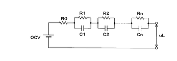
- 6A, 6B, and 6C are explanatory diagrams illustrating an equivalent circuit model of a unit battery (battery module 11 or battery cell 11a).
- the equivalent circuit is represented by a circuit in which a resistor Ra and a parallel circuit of a resistor Rb and a capacitor Cb are connected in series to a voltage source having an open circuit voltage as an electromotive force.
- the resistance Ra corresponds to the electrolyte resistance.
- the resistor Rb corresponds to the charge transfer resistance.
- the capacitor Cb corresponds to the electric double layer capacitance.
- the resistor Ra may include a charge transfer resistor, and the resistor Rb may correspond to a diffused resistor.
- the equivalent circuit of the unit battery is not limited to that shown in FIG. 6A.
- the internal parameters of the equivalent circuit model shown in FIGS. 6A, 6B, and 6C are obtained by estimating the parameters in the approximate expression using the voltage value and the current value, for example, by the least square method.
- a known method may be used for this parameter estimation method (see, for example, “Battery Management Engineering” Shuichi Adachi et al., Tokyo Denki University Publishing, Chapter 6.2.2).
- the internal parameters Ra, Rb, and Cb may be calculated using a Kalman filter.
- the parameter calculation unit 130 is an observation vector when an input signal expressed by a terminal voltage and a current is given to the unit battery, and a state when the same input signal is given to the equivalent circuit model of the unit battery. Compare with vector. As a result of the comparison, the parameter calculation unit 130 repeatedly corrects the equivalent circuit model so that the error between both vectors is minimized by multiplying the error between the two by the Kalman gain and feeding back to the equivalent circuit model. In this way, the parameter calculation unit 130 can also estimate the internal parameters.
- the module control unit 12a calculates the full charge capacity for each battery cell 11a.
- Various methods can be adopted as a method for calculating the full charge capacity by the full charge capacity calculation unit 131.
- the full charge capacity calculation unit 131 performs the first charging of the battery cell 11a at the first time point when the start switch is in the OFF state within the first trip period from the ON time point of the start switch of the vehicle V to the next ON time point.
- the first charging rate is calculated by the charging rate calculation unit 129 by applying the open circuit voltage to the stored correlation.
- the full charge capacity calculation unit 131 calculates the second charge rate by the charge rate calculation unit 129 based on the second open circuit voltage at the second time point when the start switch is in the OFF state during the second trip period.
- the full charge capacity calculation unit 131 calculates the charge / discharge amount based on the charge / discharge current acquired by the current acquisition unit 126 between the first time point and the second time point by the current integration unit 128.
- the full charge capacity calculation unit 131 calculates the full charge capacity of each battery cell 11a based on the calculated first charge rate, second charge rate, and charge / discharge amount.
- the full charge capacity calculation unit 131 can also calculate the full charge capacity for each battery module 11 based on the full charge capacity for each battery cell 11a. As a method for calculating the full charge capacity, other known methods or new methods may be used.
- the module control unit 12a calculates the deterioration level for each unit battery that is the battery module 11 or the battery cell 11a.
- the deterioration degree calculation unit 132 calculates the deterioration degree by comparing the full charge capacity of the unit battery calculated by the full charge capacity calculation unit 131 with the initial full charge capacity stored in the recording unit 123. .
- the deterioration degree calculation unit 132 obtains the ratio (increase) of the internal resistance value R calculated by the parameter calculation unit 130 to the initial value R0 for the secondary battery 10 and stores the internal resistance stored in the recording unit 123.
- the degree of deterioration may be calculated based on the correlation between the increase rate and the discharge capacity ratio. Further, the deterioration degree calculation unit 132 may calculate the deterioration degree by comparing the initial value of the equivalent circuit parameter stored in the recording unit 123 with the value calculated by the parameter calculation unit 130.
- Battery characteristics can be calculated by various methods as the above-described charging rate calculation unit 129, parameter calculation unit 130, full charge capacity calculation unit 131, and deterioration degree calculation unit 132.
- the charging rate calculation unit 129, the parameter calculation unit 130, the full charge capacity calculation unit 131, and the deterioration degree calculation unit 132 are disclosed in, for example, Japanese Patent Laid-Open Nos. 2018-013456, 2017-203659, and 2017-194284. The method disclosed in JP-A-2017-194283 and the like may be used.
- the module control unit 12a calculates, as a control unit 121, all or a part of battery characteristics such as a charging rate, an equivalent circuit parameter, a full charge capacity, and a deterioration degree at a predetermined cycle such as 10 milliseconds, and temporarily stores them. Then, charge / discharge control according to the battery characteristics is performed.
- the control unit 121 outputs the battery characteristics to the battery monitoring device 4, and the battery monitoring device 4 calculates the battery characteristics of the entire secondary battery 10 and performs charge / discharge control as a whole, or traveling control to other in-vehicle devices. Provide information to
- the recording unit 123 records these pieces of information indicating the sequentially calculated battery characteristics in association with the time information in the memory 12e at a predetermined recording timing.
- FIG. 7 is a diagram illustrating an example of the content of information recorded by the recording unit 123.
- the recording unit 123 associates information indicating the battery characteristics (FCC, SOC, SOH, or equivalent circuit parameters) with the unit battery identification information (MID / CID) and the management device identification information (BMU-ID), so that the timer 122 It is recorded with time information (calculation time) that can be acquired with.
- the recording timing is, for example, the timing at which the start switch is turned on from the off state at regular intervals such as once a month.
- the recording unit 123 continuously determines whether or not the recording timing has arrived, and performs recording processing when determining that it has arrived.
- the recording timing may be an instruction from the battery monitoring device 4 or a timing when a request is made. In this case, a request may be made via a communication medium from another in-vehicle control device (not shown).
- the recording process is continuously performed by the battery management device 12 in both the vehicle V in which the new secondary battery 10 is mounted and the vehicle V in which the reused secondary battery 10 is mounted.
- the battery characteristics are recorded by the recording unit 123 so as to be identifiable for each unit battery (battery module 11 or battery cell 11a) and in association with time information.
- the battery characteristics recorded by the recording unit 123 can be read later.
- a reading device such as a diagnostic terminal is used, and the reading device is connected to the communication unit 45 of the battery monitoring device 4 via a vehicle gateway device (not shown) so as to be communicable.
- the reading device can read the battery characteristics recorded in the recording unit 123 in association with the unit battery identification information (MID / CID) and the management device identification information (BMU-ID).
- the operator separately uses a terminal corresponding to the input / output unit 12d, and the battery characteristics recorded by the recording unit 123 on this terminal are used as unit battery identification information (MID / (CID) and management device identification information (BMU-ID) may be read in association with each other.
- MID / (CID) unit battery identification information
- BMU-ID management device identification information
- the battery information processing system including the charging rate calculation unit 129 that calculates the battery characteristics, the parameter calculation unit 130, the full charge capacity calculation unit 131, the deterioration degree calculation unit 132, and the recording unit 123.
- the secondary battery reuse system 100 can collect battery characteristics for each unit battery identification information (MID / CID) and management device identification information (BMU-ID) read when the vehicle V is inspected. Accordingly, it is possible to quickly manage which identification information of the battery module 11 or the battery cell 11a should be combined. The state of each battery module 11 or each battery cell 11a can be detected without performing another measurement when the secondary battery 10 is disassembled.
- the module control unit 12a of the battery management device 12 detects whether or not the replacement time has arrived from the state of detection based on the battery characteristics recorded by the recording unit 123. You may make it notify the arrival of replacement
- the battery information processing system included in the secondary battery reuse system 100 includes a plurality of battery management devices 12 that calculate battery characteristics for each of a plurality of unit batteries, and a record that records the calculated battery characteristics.
- Apparatus the control unit 40 and the memory 44 in FIG. 8).
- FIG. 8 is a block diagram showing a part of the configuration of the in-vehicle communication system in the second embodiment.
- the in-vehicle communication system shown in FIG. 8 is a system in the vehicle V included in the secondary battery reuse system 100 shown in the first embodiment.
- the components common to the first embodiment are denoted by the same reference numerals, and detailed description thereof is omitted.
- the vehicle V is mounted with an in-vehicle communication system including a battery monitoring device 4 connected to the secondary battery 10, a GW (Gateway) device 2 connected to the in-vehicle LAN, and an ECU 5. .
- the GW apparatus 2 includes a control unit 20 and an in-vehicle communication unit 21.
- the control unit 20 uses one or more processors and a memory to execute processing for controlling each component.
- the GW apparatus 2 is a communication apparatus that relays information between different communication media included in the in-vehicle LAN.
- the in-vehicle communication unit 21 realizes transmission / reception of information between the battery monitoring device 4 and another ECU 5 by in-vehicle communication.
- the in-vehicle communication unit 21 performs communication by CAN communication, but may perform communication by wired communication or wireless communication using another protocol.
- the ECU 5 is an in-vehicle device that includes a control unit 50, an in-vehicle communication unit 51, a display unit 52, and an audio output unit 53, and exhibits a function of outputting a message for a passenger. Note that only one of the display unit 52 and the audio output unit 53 may be provided.
- the control unit 50 controls the display unit 52 and the audio output unit 53 using a microcomputer.
- the in-vehicle communication unit 51 is connected to the in-vehicle LAN to realize transmission / reception of information with other in-vehicle devices.
- the display unit 52 is an indicator lamp provided in a panel of instruments including a speedometer on the instrument panel.
- the display unit 52 may use an LED (Light Emitting Diode).
- the display unit 52 may be a head-up display.
- the display unit 52 incorporates a touch panel used in a navigation system or the like, and may use a display panel such as an LCD (Liquid Crystal Display) or an organic EL (Electro Luminescence).
- the display unit 52 displays images or characters based on the control of the control unit 50.
- the sound output unit 53 is a speaker and emits sound or sound effect based on the control of the control unit 50.
- FIG. 9 is a functional block diagram of the control unit 40 of the battery monitoring device 4 according to the second embodiment.
- the control unit 40 of the battery monitoring device 4 functions as a battery characteristic acquisition unit 401, a recording unit 402 that records battery characteristics in the memory 44, and a replacement time detection unit 403.
- the module control unit 12a of the battery management device 12 serves as the recording unit 123 that sequentially records the battery characteristics in the memory 12e, which is a nonvolatile storage medium, even if the battery characteristics to be sequentially calculated are temporarily stored. Does not have to work.
- the battery characteristic acquisition unit 401 acquires the battery characteristics transmitted from the battery management device 12 of each battery module device 1 through the input / output unit 43 together with time information. Thereby, the battery monitoring device 4 functions as a battery characteristic reading device.
- the recording unit 402 performs processing for recording the battery characteristics acquired via the input / output unit 43 in the memory 44 at a predetermined timing.
- the replacement time detection unit 403 refers to information recorded in the memory 44 at a predetermined timing, and executes processing related to detection of abnormality in the secondary battery 10 and promotion of provision of the secondary battery 10 for reuse.
- FIG. 10 is a flowchart showing an example of a processing procedure in the in-vehicle communication system.
- the control unit 40 of the battery monitoring device 4 determines whether it is a recording timing (step S401).
- the recording timing is, for example, every fixed period such as once a month.
- the control unit 40 determines that it is the recording timing when a certain period of time has elapsed and the start switch is next turned on from the off state.
- control unit 40 determines that it is not the recording timing (S401: NO), it returns the process to step S401.
- the control unit 40 sequentially instructs the battery management device 12 of each battery module device 1 to read (step S402).
- the control unit 121 sequentially calculates (for example, 10 milliseconds) in accordance with an instruction from the battery monitoring device 4 and reads out the temporarily stored battery characteristics (step S101).
- the control unit 121 associates the read battery characteristics with the unit battery identification information (CID / BID) and management device identification information (BMU-ID) stored in the recording unit 123, and inputs / outputs the data to the battery monitoring device 4. 12d is output (step S102).
- the control unit 121 also outputs time information for calculating the output battery characteristics.
- the control unit 40 receives the battery characteristics transmitted from the battery management device 12 in response to the read instruction, at the communication unit 45 (step S403).
- the control unit 40 acquires travel information (travel distance, average speed, fuel consumption, etc.) of the vehicle V from another device via the in-vehicle LAN by the communication unit 45 (step S404).
- the control unit 40 records the received battery characteristics in the memory 44 in association with the unit battery identification information (CID / BID), the management apparatus identification information (BMU-ID), and the travel information acquired in Step S404 (Step S404). S405). In step S405, the control unit 40 also records the time information received correspondingly.
- control unit 40 Based on the battery characteristics recorded in time series in the memory 44, the control unit 40 refers to the travel information, and whether the replacement time of the secondary battery 10 has already arrived or does it come within one year thereafter It is determined whether or not (step S406).
- the control unit 40 may determine whether or not it is predicted to arrive within one year, and may determine that it has arrived when it is determined that it will arrive. In step S406, in particular, the control unit 40 determines that the replacement time has come when the degree of deterioration is a predetermined rate, for example, 70%, that is, when the full charge capacity is 70% or less compared to the new state. Further, the control unit 40 may determine whether or not the output voltage at the time of full charge is equal to or lower than a predetermined ratio as compared with a new state. When the fuel consumption included in the travel information is in a deteriorated state, the control unit 40 may determine that the replacement time has arrived.
- a predetermined rate for example, 70%
- the control unit 40 may determine whether or not the output voltage at the time of full charge is equal to or lower than a predetermined ratio as compared with a new state.
- step S406 If it is determined in step S406 that the replacement time has not arrived (S406: NO), the control unit 40 ends the process. In this case, the control unit 40 stands by again from step S401 until it is the recording timing.
- step S406 When it is determined in step S406 that the replacement time has arrived or has arrived (S406: YES), the control unit 40 transmits an arrival notification of the replacement time of the secondary battery 10 from the communication unit 45 to the ECU 5. (Step S407). And the control part 40 of the battery monitoring apparatus 4 complete
- the ECU 5 receives the arrival notification by the in-vehicle communication unit 51 (step S501), and the control unit 50 displays a message indicating the replacement time on the display unit 52 (step S502), and sounds a warning sound.
- the output is output from the output unit 53 (step S503).
- the control unit 40 notifies the arrival of the replacement time separately from the abnormality detection of the secondary battery 10, so that the battery module 11 or the battery is deteriorated before it can be used even in reuse.
- the replacement of the cell 11a can be promoted.
- the battery monitoring device 4 connected to all the battery management devices 12 rather than each of the battery management devices 12 collects the battery characteristics and records them so that they can be read later. It is possible to make a comprehensive judgment on the arrival of time, including driving information.
- FIG. 11 is a diagram showing an outline of the secondary battery reuse system 200 in the third embodiment.
- the battery characteristics for each unit battery of the secondary battery 10 of each vehicle V are collected by the server device 3 existing outside the vehicle V and recorded in the database 301.
- the secondary battery reuse system 200 of Embodiment 3 includes a plurality of battery management devices 12 that calculate battery characteristics for each of a plurality of unit batteries, and a recording device (server device 3 and database 301) that records the calculated battery characteristics. Including a battery information processing system.
- the server device 3 and the database 301 are managed by the vehicle V that inspects the secondary battery 10, the inspection organization of the secondary battery 10, an inspection service provider that is a third party, or the like.
- the GW device 2 shown in the second embodiment has a function of communicating with the outside of the vehicle in addition to the in-vehicle communication unit 21, and can transmit / receive information to / from the server device 3 via the network N.
- the network N includes a public communication network and a carrier network that realizes wireless communication according to a predetermined mobile communication standard. It may include a network of optical beacons and ITS (Intelligent Transport Systems).
- the processing in the battery management device 12 and the battery monitoring device 4 in the third embodiment is the same as the processing described in the first and second embodiments, except for the processing for setting the recording location as the database 301.
- the configurations common to the first and second embodiments are denoted by the same reference numerals, and detailed description thereof is omitted.
- FIG. 12 is a block diagram showing a part of the configuration of the in-vehicle communication system according to the third embodiment.
- the GW apparatus 2 includes an out-of-vehicle communication unit 22.
- the vehicle exterior communication unit 22 is a unit that transmits and receives information to and from a communication device (including a wireless communication device brought into the vehicle) other than the vehicle-mounted device.
- the communication unit 22 outside the vehicle is connected to the network N via the communication device, and can send and receive information to and from the server device 3.
- the out-of-vehicle communication unit 22 is a wireless communication unit capable of communication connection to an access point AP of a communication network provided by a communication carrier provided by Wi-Fi communication.
- the external communication unit 22 may use Bluetooth (registered trademark).
- the vehicle exterior communication unit 22 may be a wireless communication module according to a predetermined mobile communication standard.
- the outside communication unit 22 may transmit / receive information to / from the server device 3 via the communication device outside the vehicle and the network N using an optical beacon or an ITS wireless communication standard.
- the communication unit 22 outside the vehicle may be an interface such as a diagnosis port for abnormality diagnosis or log extraction, and the control unit 20 may transmit information from the communication unit 22 outside the vehicle to a predetermined diagnosis terminal. In this case, the information received by the diagnosis terminal is transmitted to the server device 3 via the network N via the terminal device used in the inspection organization.
- FIG. 13 is a block diagram of the server device 3.
- the server device 3 uses a server computer and includes a control unit 30, a recording unit 31, and a communication unit 32.
- the server apparatus 3 is described as a single server computer, but a configuration in which a plurality of server computers perform processing in a distributed manner may be used.
- the control unit 30 is a processor using a CPU or a GPU (Graphics Processing ⁇ Unit), and executes processing by controlling each component using a built-in memory such as a ROM and a RAM.
- the control unit 30 executes information processing based on the computer program recorded in the recording unit 31.
- the recording unit 31 uses a non-volatile storage medium such as a hard disk, SSD (Solid State Drive), flash memory, or the like.
- the recording unit 31 records information indicating battery characteristics in the database 301 in association with unit battery identification information (MID / CID) for identifying each unit battery (battery module 11 or battery cell 11a).
- the database 301 may be configured by a storage device outside the server device 3.
- the communication unit 32 is a communication device that realizes communication connection and data transmission / reception via the network N.
- the communication unit 32 is a network card corresponding to the network N.
- FIG. 14 is a flowchart illustrating an example of a processing procedure of each device in the secondary battery reuse system 200 according to the third embodiment.
- the control unit 40 of the battery monitoring device 4 receives battery characteristics from the battery management device 12 (S403), and acquires travel information of the vehicle V via the in-vehicle LAN (S404).
- the control unit 40 associates the battery characteristics received in step S403 with identification information such as unit battery identification information (CID / BID) and management device identification information (BMU-ID) and the travel information acquired in step S404. It transmits to server apparatus 3 address (step S415).
- step S415 the control unit 40 transmits both the time information received from the battery management device 12 corresponding to the battery characteristics and the vehicle body identification information of the vehicle V.
- the communication unit 32 receives the battery characteristics (step S301).
- the control unit 30 records the battery identification received by the communication unit 32 in the database 301 in association with the unit battery identification information (CID / BID) and the management device identification information (BMU-ID) (step S302).
- the control unit 30 records the time information received correspondingly in the database 301.
- the control unit 30 reads the battery characteristics recorded for each unit battery in the database 301 (step S303). Thereby, the server device 3 functions as a battery characteristic reading device. Based on the read battery characteristics, the control unit 30 determines whether or not the replacement time has arrived for each vehicle V, that is, for each secondary battery 10 (step S304). In step S304, the control unit 30 collects battery characteristics for each unit battery associated with the same vehicle body identification information, and as described in step S405 of the flowchart of FIG. Judgment may be made based on the travel information. When the server device 3 with sufficient hardware resources can determine whether or not the replacement time has come, the control unit 30 performs statistical processing (regression analysis) in advance based on the recording of time-series battery characteristics for each unit. , T method, etc.) or deep learning. In these determination methods, the control unit 30 uses a learning model prepared in advance to output the predicted unit battery life when the input is battery characteristics, and refers to the output life. It is good to judge.
- step S304 If it is determined in step S304 that the replacement time has not arrived (S304: NO), the control unit 30 ends the process.
- step S304 When it is determined in step S304 that the replacement time has arrived or has arrived (S304: YES), the control unit 30 transmits an exchange time arrival notification to the vehicle V (step S305), and ends the process. To do.
- step S304 the control unit 30 sends vehicle body identification information, unit battery identification information (CID / BID), and management device identification information (manufactured by another vehicle V manufacturer, dealer, inspector, or secondary battery 10 manufacturer).
- BMU-ID management device identification information
- the unit battery included in the secondary battery 10 in use can be replaced with a new secondary battery 10 or a regenerated secondary battery 10 while being recognized by a dealer or a manufacturer. It is possible to realize a service such as presenting the merits of this to the user and promote the use of the secondary battery reuse system 200.
- the battery monitoring device 4 or the ECU 5 receives the arrival notification from the server device 3 (step S416), and notifies the user of the arrival of the replacement time using the in-vehicle display unit 52 or the like.
- the server device 3 outside the vehicle V records the battery characteristics in the database 301 for each unit battery. Although it is desirable to simplify the device mounted on the vehicle V as much as possible, it can be expected to make a highly accurate judgment by recording the server device 3 having abundant resources so that it can be read. Further, by making the determination at the server device 3, not only can the user know that the replacement time has arrived, but also notification to the battery manufacturer and the manufacturer of the vehicle V can be easily realized. It is also easy to realize a service that prompts the secondary battery reuse system 200 to provide a unit battery at the time of inspection by the manufacturer of the vehicle V. By providing the unit battery to the secondary battery reuse system 200, it is possible to present a merit such as a price discount for the new secondary battery 10 from the manufacturer of the vehicle V.
- FIG. 15 is a diagram showing an outline of the secondary battery reuse system 300 in the fourth embodiment.
- battery characteristics are recorded by a distributed DB network system 600 called a so-called block chain.
- the distributed DB network system 600 includes a storage medium and includes a plurality of nodes 601 that perform predetermined calculations.
- a secondary battery reuse system 300 according to Embodiment 4 includes a plurality of battery management devices 12 that calculate battery characteristics for each of a plurality of unit batteries, and a recording device (distributed DB network system) that records the calculated battery characteristics. Including a battery information processing system.
- a vehicle V is mounted on a vehicle V, which is a communication device having a secret key itself or a wallet address based on the secret key.
- the in-vehicle node 6 can be connected to the battery monitoring device 4 to acquire the battery characteristics for each unit battery of the secondary battery 10.
- the secret key itself is assigned to each unit battery, and the in-vehicle node 6 stores and uses the wallet address based on the secret key for each unit battery included in the secondary battery 10 of the vehicle V in which it is mounted. Also good.
- a plurality of wallet addresses that can be created based on the secret key corresponding to the in-vehicle node 6 may be assigned to each of the plurality of unit batteries included in the secondary battery 10.
- the wallet address of each unit battery may be used as unit battery identification information.
- FIG. 16 is a block diagram showing a part of the configuration of the in-vehicle communication system according to the fourth embodiment.
- the vehicle-mounted node 6 connected to the battery monitoring device 4 so as to be communicable is mounted on the vehicle V.
- the in-vehicle node 6 includes a processing unit 60, a memory 61, an in-vehicle communication unit 62, and an out-of-vehicle communication unit 63.
- the processing unit 60 uses a processor such as a CPU and a GPU, and a memory.
- the processing unit 60 may be configured as one piece of hardware (SoC: System On a Chip) in which a processor, a memory, and further a memory 61, an in-vehicle communication unit 62, and an out-of-vehicle communication unit 63 are integrated.
- SoC System On a Chip
- the secret key may be stored in the memory of the processing unit 60 in a non-rewritable manner in hardware (wallet chip).
- the memory 61 uses a flash memory and stores information such as programs and data referred to by the processing unit 60.
- the above-described secret key may be stored in the memory 61.
- the memory 61 stores a public key based on the secret key and a wallet address.
- the in-vehicle communication unit 62 realizes information transmission / reception with the battery monitoring device 4.
- the in-vehicle node 6 may not communicate with other in-vehicle devices other than the battery monitoring device 4.
- the in-vehicle communication unit 63 is a unit that transmits and receives information by wireless signals to and from communication devices other than the in-vehicle device (including wireless communication devices brought into the vehicle).
- the communication unit 63 outside the vehicle is communicably connected to the network N via the communication device, and can transmit information to any one of the plurality of nodes 601 included in the distributed DB network system 600.
- the vehicle exterior communication unit 63 is, for example, a wireless communication module according to a predetermined mobile communication standard.
- the out-of-vehicle communication unit 63 is a wireless communication unit capable of communication connection to an access point AP of a communication network provided by a communication provider.
- the external communication unit 63 may use Bluetooth (registered trademark).
- the in-vehicle node 6 configured in this way outputs (transmits) a transaction for recording battery characteristics to the distributed DB network system 600 including the node 601 and the nodes 601 outside the vehicle V.
- a signature based on the wallet address (unit battery identification information) stored in the in-vehicle node 6 is used.
- a transaction for transmitting battery characteristics from the wallet address of the in-vehicle node 6 to the wallet address of a specific node (registration node) can be used.
- the battery characteristics may be transmitted after being converted to a hash value.
- a transaction for recording battery characteristics based on the wallet address of each in-vehicle node 6 in the distributed DB network system 600 undergoes a process of verifying a signature included in the transaction using the public key of the in-vehicle node 6, and any node 601. In addition, it is recorded so that it can be browsed via communication from a device outside the distributed DB network system 600.
- the use of the battery characteristics recorded in the distributed DB network system 600 will be described.
- the battery characteristics recorded in the distributed DB network system 600 can be confirmed as highly accurate battery characteristics for each unit battery as shown in the first to third embodiments. Therefore, it is possible for an operator to grasp the degree of deterioration of each unit battery without an inspection at the stage of disassembling the secondary battery 10.
- the in-vehicle node 6 that can output a transaction to the distributed DB network system 600 that is a so-called block chain, it is possible to distribute information on the unit battery on the distributed DB network system 600.
- FIG. 17 is a diagram showing an outline of information distribution in the distributed DB network system 600.
- the in-vehicle node 6 outputs a transaction for recording the battery characteristics with high accuracy obtained by the battery management device 12 for each unit battery.
- distribution of unit cells as resources can be recorded.
- the distributed DB network system 600 may be provided with a specific node 601 configured to execute a smart contract for processing a transaction for registering a transfer.
- each unit battery included in the secondary battery 10 is mounted on the vehicle V from a specific node managed by the manufacturer of the secondary battery 10 or the manufacturer of the vehicle V itself.
- a transaction for transferring the unit battery identification information (CID / BID) to the in-vehicle node 6 is output.
- the wallet address of the in-vehicle node 6 to which the unit battery identification information (CID / BID) is transferred becomes clear on the distributed DB network system 600.
- the transaction at the time of recombination may transfer unit battery identification information (CID / BID) from the in-vehicle node 6 of the original vehicle V to a specific node 601 managed by the battery supplier performing the recombination.
- the transfer transaction is set so that recording to the distributed DB network system 600 can be realized for the first time by multisig using a secret key or the like corresponding to each of the transfer source node and the transfer destination node (device). Good. Further, at the time of relocation, a transaction for paying the price of virtual currency may be recorded as a consideration for relocation between the in-vehicle nodes 6. As a result, for the provision of the unit battery to the secondary battery reuse system 300, the vehicle V itself can be paid with a digital asset such as a virtual currency.
- the secret key of the vehicle-mounted node 6 of the vehicle V is managed by the user who is the owner of the vehicle V, so that the virtual currency can be paid to the owner who provides the secondary battery 10.
- the transfer transaction is, for example, a node such as the in-vehicle node 6 via a node that can be operated by an owner who knows the secret key of the secondary battery 10 (initially, the manufacturer of the secondary battery 10 or the manufacturer of the vehicle V). It is good to output by accepting a transfer instruction.
- the function of the in-vehicle node 6 shown in the fourth embodiment may be incorporated in the battery monitoring device 4.
- the distributed DB network system 600 to record the battery characteristics, identification information, and the like related to the unit batteries included in the secondary battery 10, it is possible to activate the distribution of the unit cells that are resources, Traceability can be improved and the value of the unit cell can be guaranteed.
- the secondary battery 10 has been described with reference to an example in which the secondary battery 10 is first used to supply driving power for the vehicle V.
- the secondary battery reuse system 100 (200 or 300) records not only the vehicle V but also secondary battery such as carts, battery characteristics in use in stationary power storage devices, etc., so that it can be collected. May be.
- the secondary battery reuse system 100 (200 or 300) of the present disclosure can be applied to any system that uses a secondary battery in which a plurality of unit batteries (battery cells 11a or battery modules 11) are combined.
Abstract
複数の単位電池を含む二次電池に接続されて二次電池の特性を示す情報を処理する電池管理装置は、前記二次電池の電池特性を単位電池毎に算出する算出部と、該算出部により算出された前記単位電池毎の電池特性を、単位電池を識別する単位電池識別情報、及び、算出された時間を示す時間情報に対応付けて記録する記録部とを備える。
Description
本発明は、電池管理装置、電池情報処理システム及び電池情報処理方法に関する。本出願は、2018年6月1日出願の日本出願第2018-106343号に基づく優先権を主張し、前記日本出願に記載された全ての記載内容を援用するものである。
HEV(Hybrid Electric Vehicle:ハイブリッド自動車)及びEV(Electric Vehicle:電気自動車)等の車輌が普及しつつある。HEV及びEVは二次電池を搭載している。車輌に搭載されている二次電池は、複数の電池セルを組み合わせた電池モジュールを更に複数組み合わせて組電池として構成されている。電池セル及び電池モジュールは夫々、個別に電池特性を有する。類似又は同等の電池特性の電池セル及び電池モジュールを組み合わせて1つの組電池として製造されるが、使用による充放電を繰り返した後、電池特性にバラつきが発生する。使用開始から期間が経過した組電池から、再利用可能な電池モジュールを選別し、組電池を再構成する方法が提案されている。
特許文献1には、組電池に含まれる電池モジュール、又は電池セル毎に満充電容量、劣化度等の電池特性を全て測定し、再利用可能か否かを判定する方法が開示されている。
非特許文献1には、組電池を回収し、回収された組電池の全ての電池モジュールの性能(満充電容量、劣化度)を測定して分類し、再利用することが開示されている。回収された電池モジュールは、HEV,EVの駆動に再利用するもの、フォークリフト等の産業用車輌に再利用するもの、バックアップ電源等に再利用するものに分類される。
二次電池の電池特性の導出方法は、非特許文献2に開示されているように、等価回路の要素のパラメータを算出する方法や、特許文献2から特許文献5に開示されているような方法が提案されている。
"フォーアールエナジー、「リーフ」の充電池を再製品化する浪江事業所の事業について説明"、[online]、株式会社インプレス、Car Watch、[平成30年 4月11日検索]、インターネット(URL: https://car.watch.impress.co.jp/docs/news/1113869.html)
「バッテリマネジメント工学」足立修一他著、東京電気大学出版、6.2.2章参照
本開示に係る電池管理装置は、複数の単位電池を含む二次電池における電池特性を、単位電池毎に算出する算出部と、該算出部により算出された前記単位電池毎の電池特性を、単位電池を識別する単位電池識別情報、及び、算出された時間を示す時間情報に対応付けて記録する記録部とを備える。
[本開示が解決しようとする課題]
特許文献1、及び非特許文献1に開示されている二次電池の再利用では、組電池の解体時に測定を行なって評価している。非特許文献1では、48個の電池モジュールについて計4時間で測定を終えることができるとしているが、小型のEV1台分の電池モジュールについて4時間では依然として長い時間を要していると言える。解体時点での一時的な計測で得られる電池特性での測定評価では、真に一様な電池特性の電池モジュール又は電池セルを組み合わせることは困難である。
特許文献1、及び非特許文献1に開示されている二次電池の再利用では、組電池の解体時に測定を行なって評価している。非特許文献1では、48個の電池モジュールについて計4時間で測定を終えることができるとしているが、小型のEV1台分の電池モジュールについて4時間では依然として長い時間を要していると言える。解体時点での一時的な計測で得られる電池特性での測定評価では、真に一様な電池特性の電池モジュール又は電池セルを組み合わせることは困難である。
従来技術では上述したように電池特性の測定時間の課題、一様な電池特性の電池モジュール又は電池セルの組み合わせの困難性の課題があるため、二次電池の再利用即ち資源の効率的使用が遅々とし進まない。
本願は、二次電池に含まれているレアアース等の資源の効率的な使用に貢献し得る電池管理装置、電池情報処理システム及び電池情報処理方法を提供することを目的とする。
[本開示の実施形態の説明]
最初に本開示の実施態様を列記して説明する。また、以下に記載する実施形態の少なくとも一部を任意に組み合わせてもよい。
最初に本開示の実施態様を列記して説明する。また、以下に記載する実施形態の少なくとも一部を任意に組み合わせてもよい。
(1)本態様に係る電池管理装置は、複数の単位電池を含む二次電池における電池特性を、単位電池毎に算出する算出部と、該算出部により算出された前記単位電池毎の電池特性を、単位電池を識別する単位電池識別情報、及び、算出された時間を示す時間情報に対応付けて記録する記録部とを備える。
本態様にあっては、二次電池に含まれる単位電池(電池セル、又は複数の電池セルを接続した電池モジュール単位)で電圧、電流、又は温度に基づき算出された電池特性が装置内に、単位電池を識別する情報及び算出された時間を示す時間情報と対応付けて記録される。記録されている電池特性を事後的に読み出すことができるので、再利用又は再生時の測定を必須とせず詳細な電池特性を得ることができる。
二次電池をリユースするため解体する時点という一時的な電池特性ではなく、二次電池の充放電を単位電池毎に管理する装置自身が、充放電のタイミングに合わせて測定し算出する電池特性の長時間に亘る履歴に基づき、単位電池毎の状態を特定することを可能とする。
単位電池毎に、単位電池識別情報に対応付けて電池特性の履歴を記録しておくことにより、多数の単位電池について履歴を収集して、いずれの単位電池を組み合わせて再利用すべきかを迅速に特定することができる。単位電池のトレーサビリティを向上させ、単位電池毎の再利用を促すことができる。単位電池を、実際に使用した際の電池特性を用いて特性が揃えられた組電池として再利用することで、各々の単位電池の急激な劣化を防止することもでき、即ち資源を効率的に使用することができる。
(2)前記制御部は、前記記録部に記録された電池特性に基づき、前記二次電池の交換時期の到来を検知する。
本態様にあっては、電池特性の履歴に基づき二次電池の交換時期を精度よく検知することが可能になる。劣化が進む前に二次電池を組み合わせて他の用途に再利用させることで、二次電池の単位電池毎の効率的使用が実現する。また二次電池に接続される装置内に設けることで簡素な構成で実現が可能である。
(3)本態様に係る電池情報処理システムは、複数の単位電池を含む二次電池の特性を示す情報を処理する電池情報処理システムであって、前記複数の単位電池に接続されており、前記単位電池毎に電池特性を算出する複数の電池管理装置と、前記単位電池毎に算出された電池特性を、前記単位電池を識別する単位電池識別情報、及び算出された時間を示す時間情報と対応付けて、前記単位電池別に記録する記録装置とを含む。
本態様にあっては、記録装置は電池管理装置内に設けられておらず、二次電池からの電力の供給を受けて動作する機器(車輌)内の別装置に設けられていたり、前記機器外の他装置にて設けられていたりしてもよい。別装置に設けられていることで、複数の単位電池の電池特性を総合的に特定したり、機器(車輌)の状態を鑑みて判断したりすることが容易である。
(4)前記記録装置は、前記二次電池からの電力の供給を受けて動作する機器と異なる装置に設けられており、前記電池管理装置は、算出された電池特性を、前記単位電池識別情報及び時間情報と対応付けて前記記録装置宛てに送信する送信部を備え、前記記録装置は、前記電池特性を受信する受信部を備え、受信した各単位電池の電池特性を前記単位電池識別情報及び時間情報に対応付けて記録する。
本態様にあっては、機器外に記録装置を設け、電池管理装置は算出した電池特性を時間情報と対応付けて記録装置に送信する。記録装置に、膨大な二次電池の電池特性が記録される。電池特性の分析を、ハードウェア資源を潤沢とすることが可能な機器外の装置にて実行することにより、交換時期を高精度に検知することができ、機器内で処理を完結させることなく関連機関へ通知するなどして二次電池の再利用を促し、効率化させることが期待できる。
(5)前記電池特性は、前記電池特性は、単位電池の満充電容量、充電率、劣化度及び電池等価回路パラメータの少なくとも一つを含む。
本態様にあっては、単位電池の満充電容量、充電率、劣化度及び電池等価回路パラメータのいずれかを用いて事後的に参照しても精度よく状態を特定することができる情報が記録される。
(6)前記記録装置に記録されている電池特性を読み出す読出装置を更に含み、該読出装置は、読み出した電池特性に基づき、交換時期の到来を検知する検知部を備える。
本態様にあっては、記録されている単位電池毎の電池特性の履歴を読み出す読出装置にて、電池特性の履歴に基づき二次電池の交換時期を精度よく検知することが可能になる。劣化が進行する前に、新たな二次電池に組み込むか、又は他の用途に再利用させることで、二次電池の単位電池毎の効率的使用が実現する。交換時期の検知は電池管理装置内で行なわずに読出装置で行なうことで、二次電池が設けられている機器自体の情報等の他の情報を用いた総合的な検知も可能である。
(7)前記記録装置は、情報の帰属を記録するための記録情報を、移動元に対応する秘密鍵情報から得られる電子署名に基づいて検証及び承認する演算を行なう複数の処理ノード及び記録媒体で構成され、前記演算の結果を複数の記録媒体に分散して情報を記録する分散型データベースネットワークシステムであり、前記電池管理装置に接続されており、前記電池管理装置により算出された電池特性を前記分散型データベースネットワークシステムに記録するトランザクションを、前記分散型データベースネットワークシステムへ送信するノードを備える。
本態様にあっては、電池特性の記録は所謂ブロックチェーンと呼ばれる分散型データベースネットワークシステムで行なう。電池特性を公開された状態で且つ改ざんを困難な状態にして記録することにより、単位電池夫々のトレーサビリティを向上させ、履歴情報が保証された単位電池として資源としての価値を向上させることができる。
(8)前記ノードは、単位電池毎に異なり、秘密鍵情報に基づき得られるアドレス情報を用いた署名により前記トランザクションを作成する。
本態様にあっては、電池特性の記録は、単位電池毎に異なる秘密鍵情報に基づくアドレス情報を用いた署名を用い、電池管理装置に接続されているノードから、分散型データベースネットワークシステム内の特定ノードへ向けてのトランザクションによって実現する。アドレス情報は単位電池夫々に付与されるから、単位電池識別情報としても対応する。
(9)前記分散型データベースネットワークシステムは、前記単位電池毎に、単位電池識別情報を用いて移転を登録するトランザクションを処理するノードを含む。
本態様にあっては、分散型データベースネットワークシステムを用いることにより、二次電池の新品時の移転、再利用すべく単位電池の組み替えを行なう場合の移転の記録も実現できる。単位電池という資産の移転を分散型データベースネットワークシステムに記録することにより、履歴に基づく資産として価値の評定が可能である。
(10)複数の単位電池を含む二次電池の特性を示す情報を処理する電池情報処理方法であって、前記複数の単位電池に接続されている装置が、前記単位電池毎に電池特性を算出し、前記単位電池毎に算出された電池特性を、算出された時間を示す時間情報と対応付けて、前記単位電池別に記録し、記録されている単位電池別の電池特性の履歴に基づき、前記単位電池毎に状態を特定する処理を含む。
本態様にあっては、態様(1)同様に、二次電池に含まれる単位電池(電池セル、又は複数の電池セルを接続した電池モジュール単位)で電圧、電流、又は温度に基づき算出された電池特性が装置内又は装置外に、単位電池を識別する情報及び算出された時間を示す時間情報と対応付けて記録される。記録されている電池特性を事後的に読み出し、これにより改めて測定を行なわずとも単位電池毎の状態を特定することができる。
なお、本願は、このような特徴的な構成部を備えた電池管理装置として実現することができるだけでない。電池管理装置が実行する特徴的なステップを含む電池情報管理方法、及びこれらのステップをコンピュータに実行させるためのプログラムとして実現することもできる。また、電池管理装置単体ではなく単位電池をも含めた電池モジュール装置として、該電池モジュール装置と通信により情報を送受信する通信装置とを含む車輌通信システムとして、更には該車両通信システムを備える車輌として実現することもできる。電池管理装置の構成部の一部又は全部を実現する半導体集積回路として実現したり、電池管理装置にて処理される情報を用いた電池リユースシステム、及びこれらを更に含むその他のシステムとして実現したりすることができる。
[本開示の効果]
本開示によれば、二次電池に含まれているレアアース等の資源の効率的な使用に貢献し得る電池管理装置、電池情報処理システム及び電池情報処理方法を提供することが可能となる。
本開示によれば、二次電池に含まれているレアアース等の資源の効率的な使用に貢献し得る電池管理装置、電池情報処理システム及び電池情報処理方法を提供することが可能となる。
[本願発明の実施形態の詳細]
本発明の実施形態に係る電池管理装置、及び電池情報処理システムの具体例を、以下に図面を参照しつつ説明する。なお、本発明は、これらの例示に限定されるものではなく、請求の範囲によって示され、請求の範囲と均等の意味及び範囲内でのすべての変更が含まれることが意図される。
本発明の実施形態に係る電池管理装置、及び電池情報処理システムの具体例を、以下に図面を参照しつつ説明する。なお、本発明は、これらの例示に限定されるものではなく、請求の範囲によって示され、請求の範囲と均等の意味及び範囲内でのすべての変更が含まれることが意図される。
(実施の形態1)
図1は、二次電池リユースシステム100の概要を示す図である。二次電池リユースシステム100は、EV又はHEVである車輌Vで使用された二次電池10の再利用を支援するシステムである。二次電池リユースシステム100は、使用済み二次電池10から、電池特性が同様である電池モジュール11を選別し、選別された電池モジュール11を組み合わせて二次電池10を再生することを可能とする。電池特性の内、放電時の出力電圧が依然として高く、劣化が進んでいない電池モジュールについては車輌V用の二次電池10に再利用される。電池特性、特に劣化度の度合いによって、電池モジュール11は、車輌V以外での利用、例えば、フォークリフト、ゴルフカート等の小型車輌、バックアップ電源にて使用される蓄電池での利用が可能となる。
図1は、二次電池リユースシステム100の概要を示す図である。二次電池リユースシステム100は、EV又はHEVである車輌Vで使用された二次電池10の再利用を支援するシステムである。二次電池リユースシステム100は、使用済み二次電池10から、電池特性が同様である電池モジュール11を選別し、選別された電池モジュール11を組み合わせて二次電池10を再生することを可能とする。電池特性の内、放電時の出力電圧が依然として高く、劣化が進んでいない電池モジュールについては車輌V用の二次電池10に再利用される。電池特性、特に劣化度の度合いによって、電池モジュール11は、車輌V以外での利用、例えば、フォークリフト、ゴルフカート等の小型車輌、バックアップ電源にて使用される蓄電池での利用が可能となる。
二次電池10は、例えばリチウムイオン電池を含む。二次電池10は、複数の電池セル(単位電池)11aを直列又は直並列に接続して筐体内に収容してある電池モジュール(単位電池)11を複数含んで構成されている。
実施の形態1の二次電池リユースシステム100は、複数の単位電池毎に電池特性を算出する複数の電池管理装置(図2参照)と、算出された電池特性を記録する記録装置(図4のモジュール制御部12a及びメモリ12e)とを含む電池情報処理システムを含む。二次電池リユースシステム100では、電池情報処理システムにより車輌Vに搭載されている二次電池10の電池モジュール11の電池特性が、逐次算出され、記録される。電池特性の算出方法は、温度を一定にするなど環境の一律化によらない精度の高い方法が用いられることが望ましい。再利用の決定後、解体時に初めて測定しなければならないという状況が回避され、充分な情報が記録されていれば解体時の測定は不要となり得る。電池特性の算出方法については後述する。
単位電池毎に算出された電池特性は、単位電池を識別する情報と対応付け、事後的に参照できるように記録される。これにより、二次電池10をリユースできるか否かの判断や、どの単位電池を組み合わせるべきかの測定を不要とすることができる。二次電池10がリユース品向けに提供すべき状態であるか、またどの単位電池と組み合わせるべきかの判断が、記録を参照することで可能になる。
二次電池リユースシステム100で用いる電池特性の算出について説明する。図2は、車輌Vに搭載されている装置の構成を示すブロック図である。車輌Vには、二次電池10に関して少なくとも、電池モジュール装置1、及び電池監視装置4が搭載されている。車輌Vにおける二次電池10を用いた電源システムは、電池モジュール装置1の他にリレー、発電機(ALT)、スタータモータ、電池、電気負荷、始動スイッチ、充電器等を備える。電源システムについての詳細な説明を省略する。
電池モジュール装置1は、二次電池10の一部を構成する電池モジュール11に対して1つ、電池管理装置(BMU:Battery Management Unit)12を対応付けて使用する。電池管理装置12は入出力部12d(図4参照)を有し、電池監視装置4との間で情報の受け渡しが可能である。
電池監視装置4は、制御部40、電流検出部41、入出力部43、メモリ44、通信部45及び電源部46を備える。
制御部40は、CPU(Central Processing Unit)等のプロセッサ、ROM(Read Only Memory)、RAM(Random Access Memory)、計時部、入出力インタフェース等を有するマイクロコンピュータ、専用LSI(Large-Scale Integration)、又はFPGA(Field-Programmable Gate Array )等で構成されている。制御部40は、単位電池(電池モジュール11又は電池セル11a)の電池特性を示す情報を算出する電池管理装置12との間で入出力部43を介して情報を受け渡して処理する。
電流検出部41は、例えば二次電池10の電流を検出するためのシャント抵抗又はホールセンサ等で構成され、所定のサンプリング周期にて二次電池10の充電電流及び放電電流を検出する。サンプリング周期は例えば10ミリ秒であるがこれに限らない。制御部40は、電流検出部41で検出した電流値を逐次入出力部43から各電池管理装置12へ出力する。二次電池10は、図2に示すように電池セル11aを直列接続した電池モジュール11を更に直列接続して構成されている。このため、1つの電流検出部41にて二次電池10の一端における電流を検出することによって各単位電池(電池モジュール11又は電池セル11a)に流れる電流の検出が可能である。電流検出部41は勿論、後述の電池管理装置12にて各々電流検出回路を備え、電流を検出する構成としてもよい。
入出力部43は、制御部40と複数の電池管理装置12との入出力インタフェースであり、電池管理装置12に対応する通信バスと接続される。入出力部43は無線通信モジュールに代替されて、各電池管理装置12と無線により情報を送受信してもよい。
メモリ44は、フラッシュメモリ等の不揮発性メモリを含む。メモリ44は、自装置に接続されている複数の電池管理装置12夫々の管理装置識別情報(BMU-ID)を記憶している。管理装置識別情報は予め設定により記憶されていてもよいし、制御部40が各電池管理装置12と信号を入出力して管理装置識別情報を収集してもよい。メモリ44には、二次電池10の単位電池(電池モジュール11又は電池セル11a)を識別する単位電池識別情報(MID:モジュールID/CID:セルID)が単位電池毎に記憶されてもよい。
通信部45は、車内LAN(Local Area Network)に対応して通信を実現する通信モジュールである。通信部45は例えばCAN(Controller Area Network)により、他の車載機器との間で情報を送受信することが可能である。通信部45は無線通信アンテナを有する無線通信モジュールであってもよい。
電源部46は、二次電池10から電力を所定の電圧値に変換して各構成部に供給する回路である。
このように構成される電池監視装置4では、制御部40が各電池モジュール装置1の電池管理装置12から得られる情報から二次電池10の状態を総合的に特定して異常を検知したり、他の装置との情報の送受信を実行したりする。
図3は、実施の形態1における電池モジュール装置1の構成例を示す斜視図である。電池モジュール装置1は、全体として四角柱状をなす。電池モジュール11は、夫々板状をなす複数の電池セル11aを厚み方向に積層配置されて構成されている。電池セル11aは夫々、両端部に対となる電極端子11bを有し、各端の複数の電極端子11bは積層方向に直線的に配列している。
電池モジュール11は保持部材1aによって保持されている。保持部材1aでは、電池セル11aの積層方向一端側に延長して略直方体部分が形成されており、該直方体部分の一面側に電池管理装置12を支持するための支持板12gが設けられている。
電池管理装置12は、処理を実行する回路群(図5参照)が実装された回路基板12hを備え、回路基板12hは、電池セル11aの電極端子11bが配列している一側面に対して略平行に、支持板12gに支持されている。回路基板12hの適宜箇所、電池セル11a側には接続端子12iが設けられている。複数の電池セル11aの電極端子11bは導線12jによって接続端子12iに接続されている。導線12jは、積層方向に並ぶ電極端子11bの配列に沿って配線され、一旦は電池セル11aの一の電極端子11bに接続され、他端は接続端子12iに接続されている。
図4は、電池管理装置12の構成例を示すブロック図である。図2に示した通り、電池管理装置12は、電池モジュール11夫々に対応して複数備えられているが、いずれも同様の構成を持つため、1つの電池管理装置12について説明する。
電池管理装置12は、回路基板12hに実装された自装置全体の動作を制御するモジュール制御部12a、電圧検出回路12b、温度検出回路12c、入出力部12d、メモリ12e及び電源回路12fを含む。
電圧検出回路12bは、電池モジュール11の両端電圧を所定のサンプリング周期で検出し、検出電圧を示す情報をモジュール制御部12aへ出力する。電圧検出回路12bは、電池モジュール11に含まれる複数の電池セル11a夫々の電圧を検出してもよい。サンプリング周期は例えば10ミリ秒であるが、これに限られない。
温度検出回路12cは、電池モジュール11中の複数の電池セル11aの内のいずれか1つ又は複数箇所の表面温度をモジュール制御部12aへ通知する。温度検出回路12cは、例えばサーミスタで構成された温度センサ120cを用い、温度センサ120cからの出力信号の信号レベルに基づき温度を読み取る。温度センサ120cは電池モジュール11に1つでもよいし、電池セル11a毎に1つずつ設けられていてもよい。サーミスタの使用は一例である。温度センサ120cは、測温抵抗体、半導体温度センサ、熱電対等を用いて温度を検出する等、公知の温度センサを用いてもよい。
なお温度検出は、複数の電池モジュール11の内のいずれか1つ又は複数に設置した温度センサを用いて実現されてもよい。この場合電池監視装置4が温度センサの出力信号から温度を読み取り、各電池管理装置12へ入出力部12dを介して通知する。
入出力部12dは、電池監視装置4との間の入出力端子である。電池管理装置12は入出力部12dを介して電池監視装置4との間で信号(情報)を送受信する。
メモリ12eは、フラッシュメモリ等の不揮発性メモリである。メモリ12eの書き換え不可領域(Read Only)に、自装置の管理装置識別情報(BMU-ID)が記憶してある。メモリ12eは、モジュール制御部12aの処理により生成される情報を記憶する。
電源回路12fは、電池モジュール11から供給される電力を、電池管理装置12の各構成部の駆動に適した電圧に変換し、電池管理装置12の各構成部に給電する回路である。
モジュール制御部12aは、CPU等のプロセッサ、ROM、RAM、計時部、入出力インタフェース等を有するマイクロコンピュータ、専用LSI、又はFPGA等で構成されている。モジュール制御部12aの入出力インタフェースには、電圧検出回路12b、温度検出回路12c、入出力部12d、及びメモリ12eが接続されている。
図5は、実施の形態1におけるモジュール制御部12aの機能ブロック図である。モジュール制御部12aは、装置全体を制御する制御部121、タイマ122、記録部123、入出力処理部124、電圧取得部125、電流取得部126、温度取得部127、電流積算部128、充電率算出部129、パラメータ算出部130、満充電容量算出部131、及び劣化度算出部132として機能する。
モジュール制御部12aは制御部121として各部を制御し、検出される電圧、温度及び電流に基づいて、電池モジュール11又は電池セル11aである単位電池毎の電池特性を算出する。モジュール制御部12aは電池特性として例えば満充電容量(FCC:Full Charge Capacity)、充電率(SOC:State of Charge)、劣化度(SOH:State of Health)及び等価回路パラメータを算出する。
モジュール制御部12aは内蔵する計時部を用いてタイマ122として機能する。タイマ122は、計時結果を制御部121へ出力する。制御部121は、算出した電池特性を時系列に記憶するべく、タイマ122からの出力に基づき時間情報を対応付ける。
モジュール制御部12aはメモリ12eを用いて記録部123として機能する。記録部123は、単位電池毎に算出される電池特性を示す各種情報を記録する。なおそれらの電池特性を算出するための情報がメモリ12eに記憶してある。例えば単位電池毎に充電率(SOC)を算出するために参照される情報が記録されている。例えばメモリ12eには、単位電池(電池セル11a又は電池モジュール11単位)の開放電圧(OCV:Open Circuit Voltage)と、充電率との相関関係が予め記憶されている。
またメモリ12eには、管理対象である電池モジュール11の単位電池識別情報(MID)が記憶されている。メモリ12eには、電池モジュール11を構成する複数の電池セル11a夫々の単位電池識別情報(CID)が記憶してあってもよい。単位電池識別情報(MID/CID)は、電池モジュール11を含む二次電池10を搭載した場合に、作業オペレータによって特定装置又は電池監視装置4を介して記録部123の処理により記憶されることが好ましい。電池モジュール11又は電池セル11aに夫々単位電池識別情報(MID/CID)が記憶された記憶媒体が取り付けられており、制御部121により該記憶媒体から単位電池識別情報が読み出されて記憶されてもよい。
またメモリ12eには、単位電池毎の劣化度を算出するための情報として、単位電池夫々の初期(新品時)の満充電容量又は等価回路パラメータが記憶されている。この満充電容量又は等価回路パラメータは、単位電池の接続順に記憶されているなど、区別して読み出すことが可能であるとよい。メモリ12eには、単位電池毎の劣化度を算出するための情報として、内部抵抗の増加率、劣化度に対応する放電容量比との関係が記憶してあってもよい。これらの新品時の情報は上述の作業オペレータによる作業によって記憶されるとよい。
モジュール制御部12aは入出力処理部124として、入出力部12dを介した電池監視装置4との間の情報の送受信を制御する。入出力処理部124は、単位電池毎の電池特性を示す情報(FCC、SOC、SOH、又は等価回路パラメータ)を電池監視装置4との間で送受信することが可能である。
モジュール制御部12aは、電池特性の算出に使用する電圧、温度及び電流を夫々取得する電圧取得部125、電流取得部126及び温度取得部127として機能する。
電圧取得部125は、電圧検出回路12bから出力される電池モジュール11の両端電圧又は各電池セル11aの電圧を示す情報を取得する。電圧取得部125は、電池モジュール11の両端電圧と電池セル11a夫々における電圧とをいずれも、相互に区別して取得してもよい。
電流取得部126は、入出力部12dを介して電池監視装置4から得られる電池モジュール11又は電池セル11aを流れる電流を示す情報を単位電池の電流値として取得する。
温度取得部127は、温度検出回路12cから出力される温度を示す情報を取得する。
モジュール制御部12aは電流積算部128として、電流取得部126で取得した電流値を積算する。電流の積算値は、電流を時間で積分したものであり、充電量の変化分に相当する。電流の積算値は、充電の場合には正となり、放電の場合には負となる。ある任意の期間における積算値は、当該期間における充電電流及び放電電流の値の大小に応じて正又は負となり得る。積算の算出を開始するタイミングは二次電池10、又は電池モジュール装置1若しくは電池監視装置4自体の起動タイミングである。積分値は継続的に算出される。なお所定のタイミング、例えばリユースの場合は電池モジュール11を組み替えるタイミングで積分値がリセットされるようにしてもよい。
モジュール制御部12aは充電率算出部129として、電池モジュール11又は電池セル11aである単位電池毎の充電率を算出する。充電率算出部129は、電池モジュール11又は電池セル11aである単位電池における開放電圧を求める。充電率算出部129は、求められた開放電圧を、記録部123が記憶している開放電圧と充電率との相関関係に当てはめて充電率を推定算出する。充電率算出部129は、特定の時点における充電率を基準として、電流積算部128にて積算して得られた充電電流及び放電電流と、後述の満充電容量とを用いて充電率を算出してもよい。
モジュール制御部12aはパラメータ算出部130として、単位電池に対する等価回路の各要素のパラメータを算出する。パラメータは、等価回路における抵抗値Ra,Rb,及びコンデンサの容量Cb等である。図6A、図6B及び図6Cは、単位電池(電池モジュール11又は電池セル11a)の等価回路モデルを示す説明図である。図6Aに示す等価回路モデルでは、等価回路は、開放電圧を起電力とする電圧源に、抵抗Raと、抵抗Rb及びコンデンサCbの並列回路とを直列に接続した回路によって表される。抵抗Raは電解液抵抗に対応する。抵抗Rbは電荷移動抵抗に対応する。コンデンサCbは電気二重層容量に対応する。抵抗Raに電荷移動抵抗を含めることとし、抵抗Rbが拡散抵抗に対応することにしてもよい。
単位電池の等価回路は図6Aに示すものに限定されない。等価回路は、例えば図6Bに示すように、抵抗R0に抵抗Rj及びコンデンサCj(j=1,2,…,n)の並列回路をn個直列接続し、無限級数の和による近似で表されるn次(nは自然数)のフォスタ型RC梯子回路であってもよい。更に等価回路は、図6Cに示すように、一端同士が接続されたn個の抵抗Rj(j=1,2,…,n)夫々の他端が、直列接続されたn個のコンデンサCjの間に接続されたn次のカウエル型RC梯子回路であってもよい。
図6A、図6B、及び図6Cに示した等価回路モデルの内部パラメータは、例えば電圧値及び電流値を用いた近似式におけるパラメータを最小二乗法により推定することで得られる。このパラメータの推定方法は、公知の方法を用いるとよい(例えば「バッテリマネジメント工学」足立修一他著、東京電気大学出版、6.2.2章参照)。
内部パラメータRa,Rb,Cbは、カルマンフィルタを用いて算出されてもよい。具体的にはパラメータ算出部130は、単位電池に端子電圧及び電流で表される入力信号を与えた場合の観測ベクトルと、単位電池の等価回路モデルに上記と同じ入力信号を与えた場合の状態ベクトルとを比較する。パラメータ算出部130は、比較の結果、両者の誤差にカルマンゲインを掛けて等価回路モデルにフィードバックすることにより、両ベクトルの誤差が最小となるように等価回路モデルの修正を繰り返す。このようにパラメータ算出部130は、内部パラメータを推定することもできる。
図5に戻りモジュール制御部12aの機能の説明を続ける。モジュール制御部12aは満充電容量算出部131として、電池セル11a単位でセル毎の満充電容量を算出する。満充電容量算出部131による満充電容量の算出方法は、種々の方法を採用できる。例えば満充電容量算出部131は、車輌Vの始動スイッチのオン時点から次のオン時点までの第1のトリップ期間内で始動スイッチがオフ状態である第1の時点における電池セル11aの第1の開放電圧を記憶してある相関関係に当てはめ、充電率算出部129によって第1充電率を算出する。満充電容量算出部131は、第2のトリップ期間で始動スイッチがオフ状態である第2の時点における第2の開放電圧に基づき充電率算出部129によって第2充電率を算出する。満充電容量算出部131は、電流積算部128により、前記第1の時点から第2の時点までの間で電流取得部126によって取得した充放電電流に基づいて充放電量を算出する。満充電容量算出部131は、算出した第1充電率、第2充電率及び充放電量に基づき、電池セル11a夫々のセル毎の満充電容量を算出する。満充電容量算出部131は、電池セル11a毎の満充電容量に基づいて電池モジュール11単位での満充電容量を算出することもできる。満充電容量の算出方法として、他の公知の方法又は新規の方法が用いられてもよい。
モジュール制御部12aは劣化度(SOH)算出部132として、電池モジュール11又は電池セル11aである単位電池毎の劣化度を算出する。例えば劣化度算出部132は、満充電容量算出部131により算出された単位電池の満充電容量と、記録部123に記憶してある初期の満充電容量とを比較することによって劣化度を算出する。劣化度算出部132は、二次電池10に対しパラメータ算出部130にて算出される内部抵抗値Rの初期値R0に対する割合(増加度)を求め、記録部123にて記憶してある内部抵抗増加率と放電容量比との相関関係に基づいて劣化度を算出してもよい。更に劣化度算出部132は、記録部123にて記憶してある等価回路パラメータの初期値と、パラメータ算出部130により算出された値とを比較することにより劣化度を算出してもよい。
上述の充電率算出部129、パラメータ算出部130、満充電容量算出部131、及び劣化度算出部132として電池特性を種々の方法で算出することができる。充電率算出部129、パラメータ算出部130、満充電容量算出部131、及び劣化度算出部132は例えば、特開2018-013456号公報、特開2017-203659号公報、特開2017-194284号公報、特開2017-194283号公報等に開示の方法を用いるとよい。
モジュール制御部12aは、制御部121として例えば10ミリ秒などの所定周期で充電率、等価回路パラメータ、満充電容量、及び劣化度等の電池特性の内の全部又は一部を算出し、一時記憶して電池特性に応じた充放電制御を行なう。制御部121は電池特性を電池監視装置4へ出力し、電池監視装置4では二次電池10全体の電池特性を算出して全体としての充放電制御、又は他の車載装置へ走行制御等のために情報を提供する。
実施の形態1における電池管理装置12では、記録部123が、逐次算出される電池特性を示すこれらの情報を所定の記録タイミングでメモリ12eに時間情報に対応付けて記録する。図7は、記録部123により記録される情報の内容例を示す図である。記録部123は、電池特性を示す情報(FCC、SOC、SOH、又は等価回路パラメータ)を、単位電池識別情報(MID/CID)及び管理装置識別情報(BMU-ID)と対応付けて、タイマ122で取得できる時間情報(算出時間)と共に記録する。
記録タイミングは例えば、1ヵ月に1度などの一定期間毎に、始動スイッチがオフ状態からオン状態になるタイミングである。記録部123は、記録タイミングが到来したか否かを継続的に判断し、到来したと判断したと判断した場合に記録処理を行なう。記録タイミングは、電池監視装置4からの指示、又は要求がされたタイミングであってもよい。この場合、図示しない他の車載制御装置から通信媒体を介して要求がされてもよい。記録処理は、新品の二次電池10が搭載されている車輌V、リユース品である二次電池10が搭載されている車輌Vのいずれにおいても電池管理装置12にて継続的に行なわれる。
このように記録部123によって、単位電池(電池モジュール11又は電池セル11a)毎に識別可能にまた時間情報と対応付けて電池特性が記録される。記録部123により記録された電池特性は、事後的に読み出すことができる。例えば、ダイアグ端末等の読取装置を用い、読取装置を、図示しない車載ゲートウェイ装置を介して電池監視装置4の通信部45と通信可能に接続させる。この読取装置が、記録部123に記録されている電池特性を、単位電池識別情報(MID/CID)及び管理装置識別情報(BMU-ID)と対応付けて読み出すことができる。また、個別に取り出された電池モジュール装置1に対し、作業者が入出力部12dに対応する端末を別途用い、この端末が記録部123により記録されている電池特性を単位電池識別情報(MID/CID)及び管理装置識別情報(BMU-ID)と対応付けて読み出してもよい。
このようにして実施の形態1では、電池特性を算出する充電率算出部129、パラメータ算出部130、満充電容量算出部131、及び劣化度算出部132と記録部123とを含む電池情報処理システムにより、記録タイミングの都度に、時系列に電池特性を示す電池特性が、事後的に読み出し可能に記録される。二次電池リユースシステム100では、車輌Vの点検時に読み出された単位電池識別情報(MID/CID)及び管理装置識別情報(BMU-ID)毎の電池特性を収集することができる。これにより、いずれの識別情報の電池モジュール11又は電池セル11aを組み合わせるべきかを迅速に管理することができる。二次電池10の解体時に改めて測定が行なわれることなしに、電池モジュール11又は電池セル11a毎の状態の検知が可能である。例えば電池管理装置12のモジュール制御部12aが、記録部123により記録された電池特性に基づいて検知する状態から、交換時期が到来しているか否かを検知し、到来している場合には電池監視装置4を介して交換時期の到来の通知を行なうようにしてもよい。使用中の電池特性の履歴に基づき、より精度よく交換時期を検知することが可能となる。
(実施の形態2)
実施の形態2では、電池特性の記録を各電池管理装置12ではなく、全電池管理装置12が接続している電池監視装置4にて行なう。つまり実施の形態2では、二次電池リユースシステム100に含まれる電池情報処理システムは、複数の単位電池毎に電池特性を算出する複数の電池管理装置12と、算出された電池特性を記録する記録装置(図8の制御部40及びメモリ44)とを含む。図8は、実施の形態2における車載通信システムの構成の一部を示すブロック図である。図8に示す車載通信システムは、実施の形態1に示した二次電池リユースシステム100に含まれる車輌V内のシステムである。実施の形態1と共通する構成には同一の符号を付して詳細な説明を省略する。
実施の形態2では、電池特性の記録を各電池管理装置12ではなく、全電池管理装置12が接続している電池監視装置4にて行なう。つまり実施の形態2では、二次電池リユースシステム100に含まれる電池情報処理システムは、複数の単位電池毎に電池特性を算出する複数の電池管理装置12と、算出された電池特性を記録する記録装置(図8の制御部40及びメモリ44)とを含む。図8は、実施の形態2における車載通信システムの構成の一部を示すブロック図である。図8に示す車載通信システムは、実施の形態1に示した二次電池リユースシステム100に含まれる車輌V内のシステムである。実施の形態1と共通する構成には同一の符号を付して詳細な説明を省略する。
実施の形態2において車輌Vには、二次電池10と接続される電池監視装置4と、車内LANに接続されるGW(Gate Way)装置2と、ECU5とを含む車載通信システムが搭載される。
GW装置2は、制御部20及び車内通信部21を備える。制御部20は、1又は複数のプロセッサとメモリとを用い、各構成部を制御する処理を実行する。GW装置2は、車内LANに含まれる異なる通信媒体間で情報を中継する通信装置である。
車内通信部21は、車内通信により電池監視装置4及び他のECU5との間で情報の送受信を実現する。実施の形態1では車内通信部21は、CAN通信により通信を行なうが、他のプロトコルによる有線通信又は無線通信により通信を行なってもよい。
ECU5は、制御部50、車内通信部51、表示部52及び音声出力部53を備えて搭乗者向けにメッセージを出力する機能を発揮する車載装置である。なお表示部52及び音声出力部53はいずれか一方のみであってもよい。制御部50は、マイクロコンピュータを用いて表示部52及び音声出力部53を制御する。
車内通信部51は、車内LANに接続して他の車載装置との間で情報の送受信を実現する。
表示部52は、インストルメントパネル上の速度計を含む計器類のパネル内に設けられた表示灯である。表示部52はLED(Light Emitting Diode)を用いてもよい。また、表示部52はヘッドアップディスプレイであってもよい。表示部52は、ナビゲーションシステム等で用いられるタッチパネルを内蔵したものであって、LCD(Liquid Crystal Display)又は有機EL(Electro Luminescence)等の表示パネルを用いるものであってもよい。表示部52は制御部50の制御に基づき、画像又は文字を表示する。
音声出力部53は、スピーカであって制御部50の制御に基づき、音声又は効果音を発する。
図9は、実施の形態2における電池監視装置4の制御部40の機能ブロック図である。実施の形態2では、電池監視装置4の制御部40は、電池特性取得部401、メモリ44に電池特性を記録する記録部402、及び交換時期検知部403として機能する。実施の形態2では、電池管理装置12のモジュール制御部12aは、逐次算出する電池特性については一時記憶を行なっても、不揮発性記憶媒体であるメモリ12eへ電池特性を逐次記録する記録部123としては機能しなくてよい。
電池特性取得部401は、各電池モジュール装置1の電池管理装置12から送信される電池特性を、時間情報と共に入出力部43を介して取得する。これにより電池監視装置4は、電池特性の読出装置として機能する。記録部402は、入出力部43を介して取得された電池特性を所定タイミングでメモリ44に記録する処理を行なう。
交換時期検知部403は、メモリ44に記録される情報を所定のタイミングで参照し、二次電池10における異常検知、二次電池10のリユースへの提供促進に係る処理を実行する。
図10は、車載通信システムにおける処理手順の一例を示すフローチャートである。実施の形態2において、電池監視装置4の制御部40は、記録タイミングであるか否かを判断する(ステップS401)。記録タイミングは例えば、1ヵ月に1度などの一定期間毎である。制御部40は内蔵タイマにより得られる時間情報に基づき、一定期間が経過して次に始動スイッチがオフ状態からオン状態になった場合に、記録タイミングであると判断する。
制御部40は、記録タイミングでないと判断した場合(S401:NO)、処理をステップS401へ戻す。記録タイミングであると判断された場合(S401:YES)、制御部40は、各電池モジュール装置1の電池管理装置12へ向けて順次、読み出しを指示する(ステップS402)。
各電池管理装置12では制御部121が、電池監視装置4からの指示に応じて逐次(例えば10ミリ秒)算出して一時的に記憶している電池特性を読み出す(ステップS101)。制御部121は、読み出した電池特性を、記録部123に記憶してある単位電池識別情報(CID/BID)及び管理装置識別情報(BMU-ID)と対応付けて電池監視装置4へ入出力部12dから出力する(ステップS102)。ステップS102にて制御部121は、出力した電池特性を算出した時間情報をも出力する。
制御部40は、読み出し指示に応じて電池管理装置12から送信された電池特性を通信部45にて受信する(ステップS403)。制御部40は、通信部45により車内LANを介して他装置から車輌Vの走行情報(走行距離、平均速度、燃費等)を取得する(ステップS404)。
制御部40は、受信した電池特性を、単位電池識別情報(CID/BID)及び管理装置識別情報(BMU-ID)、及びステップS404で取得した走行情報と対応付けてメモリ44に記録する(ステップS405)。ステップS405にて制御部40は、対応して受信している時間情報についても記録する。
制御部40は、メモリ44に時系列に記録されている電池特性に基づき、走行情報を参照しつつ、二次電池10の交換時期が既に到来しているか、又は以後1年以内に到来するか否かを判断する(ステップS406)。
ステップS406において制御部40は、1年以内に到来すると予測されるか否かを判断し、到来すると判断した場合に到来していると判断するようにしてもよい。ステップS406において制御部40は特に、劣化度が所定の割合、例えば70%等、つまり、満充電容量が新品の状態と比較して70%以下である場合に交換時期が到来したと判断する。また制御部40は、満充電時の出力電圧が新品の状態と比較して所定の割合以下となるか否かで判断してもよい。走行情報に含まれる燃費が悪化している状態である場合に、制御部40は交換時期が到来していると判断してもよい。
ステップS406で交換時期が到来していないと判断された場合(S406:NO)、制御部40は処理を終了する。この場合制御部40は、再度ステップS401から、記録タイミングであるまで待機する。
ステップS406で交換時期が到来する又は到来していると判断された場合(S406:YES)、制御部40は、二次電池10の交換時期の到来通知を通信部45からECU5へ向けて送信する(ステップS407)。そして電池監視装置4の制御部40は、1回の記録タイミングにおける処理を終了する。ステップS407において制御部40は、ステップS406の判断基準となった電池特性を共に送信することが好ましい。制御部40は、走行情報を共に送信してもよい。
この場合、ECU5では車内通信部51にて到来通知を受信し(ステップS501)、制御部50は、交換時期のお知らせを示すメッセージを表示部52で表示させると共に(ステップS502)、警告音を音声出力部53から出力させる(ステップS503)。
このように電池監視装置4において、制御部40が二次電池10の異常検知とは別に、交換時期の到来を通知することで、リユースでも使用できない程に劣化する前に、電池モジュール11又は電池セル11aの交換を促進することができる。実施の形態2に示したように、電池管理装置12夫々ではなく、全電池管理装置12が接続している電池監視装置4が電池特性を収集し、後に読み出し可能に記録する構成によって、特に交換時期の到来については走行情報も含めた総合的な判断が可能である。
(実施の形態3)
図11は、実施の形態3における二次電池リユースシステム200の概要を示す図である。実施の形態3では、車輌Vの外側に存在するサーバ装置3にて各車輌Vの二次電池10の単位電池毎の電池特性を収集し、データベース301に記録する。実施の形態3の二次電池リユースシステム200は、複数の単位電池毎に電池特性を算出する複数の電池管理装置12と、算出された電池特性を記録する記録装置(サーバ装置3及びデータベース301)とを含む電池情報処理システムを含む。サーバ装置3及びデータベース301は、二次電池10の検査を行なう車輌V又は二次電池10の検査機関、第三者である検査サービス事業者等で管理されるものである。
図11は、実施の形態3における二次電池リユースシステム200の概要を示す図である。実施の形態3では、車輌Vの外側に存在するサーバ装置3にて各車輌Vの二次電池10の単位電池毎の電池特性を収集し、データベース301に記録する。実施の形態3の二次電池リユースシステム200は、複数の単位電池毎に電池特性を算出する複数の電池管理装置12と、算出された電池特性を記録する記録装置(サーバ装置3及びデータベース301)とを含む電池情報処理システムを含む。サーバ装置3及びデータベース301は、二次電池10の検査を行なう車輌V又は二次電池10の検査機関、第三者である検査サービス事業者等で管理されるものである。
実施の形態3では、実施の形態2で示したGW装置2が車内通信部21の他に車外と通信する機能を備え、サーバ装置3との間でネットワークNを介した情報の送受信が可能である。ネットワークNは、公衆通信網、所定の移動通信規格による無線通信を実現するキャリアネットワークを含む。光ビーコン、ITS(Intelligent Transport Systems)のネットワークを含んでもよい。記録の場所をデータベース301とするための処理以外は、実施の形態3における電池管理装置12、電池監視装置4における処理は実施の形態1及び2に示した処理と同様である。実施の形態3における二次電池リユースシステム200の構成の内、実施の形態1及び実施の形態2と共通する構成については同一の符号を付して詳細な説明を省略する。
図12は、実施の形態3における車載通信システムの構成の一部を示すブロック図である。実施の形態3においてGW装置2は、車外通信部22を備える。車外通信部22は、車載機以外の通信装置(車内に持ち込まれた無線通信装置を含む)との間で無線信号により情報を送受信するユニットである。車外通信部22は、その通信装置を介してネットワークNに通信接続し、サーバ装置3との間で情報の送受信が可能である。車外通信部22は、Wi-Fi通信、又は通信事業者が提供する通信網のアクセスポイントAPへの通信接続が可能な無線通信ユニットである。車外通信部22は、Bluetooth(登録商標)を用いてもよい。車外通信部22は、所定の移動通信規格による無線通信モジュールであってもよい。車外通信部22は、光ビーコン、又はITS無線の通信規格を用いて車外の通信装置及びネットワークNを介してサーバ装置3との間で情報を送受信してもよい。車外通信部22は、異常診断又はログ抽出用のダイアグポート等のインタフェースであってもよく、制御部20は車外通信部22から所定のダイアグ端末へ情報を送信してもよい。この場合ダイアグ端末によって受信された情報が、検査機関で使用される端末装置を経由してネットワークNを介してサーバ装置3へ送信される。
図13は、サーバ装置3のブロック図である。サーバ装置3はサーバコンピュータを用い、制御部30、記録部31、及び通信部32を備える。本実施の形態においてサーバ装置3は、1台のサーバコンピュータとして説明するが、複数のサーバコンピュータが分散して処理を行なう構成でもよい。
制御部30は、CPU又はGPU(Graphics Processing Unit)を用いたプロセッサであり、内蔵するROM及びRAM等のメモリを用い、各構成部を制御して処理を実行する。制御部30は、記録部31にて記録されているコンピュータプログラムに基づく情報処理を実行する。
記録部31は、例えばハードディスク、SSD(Solid State Drive)、フラッシュメモリ等の不揮発性記憶媒体を用いる。記録部31は、単位電池(電池モジュール11又は電池セル11a)毎に、これらを識別する単位電池識別情報(MID/CID)と対応付けて電池特性を示す情報をデータベース301に記録する。データベース301は、サーバ装置3外の記憶装置にて構成されてもよい。
通信部32は、ネットワークNを介した通信接続及びデータの送受信を実現する通信デバイスである。具体的には通信部32はネットワークNに対応したネットワークカードである。
図14は、実施の形態3の二次電池リユースシステム200における各装置の処理手順の一例を示すフローチャートである。図14のフローチャートに示す処理手順の内、図10のフローチャートの電池管理装置12及び電池監視装置4による処理手順と共通する手順については同一のステップ番号を付して詳細な説明を省略する。
電池監視装置4の制御部40は、電池管理装置12から電池特性を受信し(S403)、車内LANを介して車輌Vの走行情報を取得する(S404)。制御部40は、ステップS403で受信した電池特性を、単位電池識別情報(CID/BID)及び管理装置識別情報(BMU-ID)等の識別情報及びステップS404にて取得した走行情報と対応付けてサーバ装置3宛てに送信する(ステップS415)。ステップS415にて制御部40は、電池管理装置12から電池特性と対応して受信している時間情報、及び車輌Vの車体識別情報についても共に送信する。
サーバ装置3では、通信部32が電池特性を受信する(ステップS301)。制御部30は、通信部32によって受信された電池特定を、単位電池識別情報(CID/BID)及び管理装置識別情報(BMU-ID)と対応付けてデータベース301に記録する(ステップS302)。ステップS302にて制御部30は、対応して受信している時間情報についてもデータベース301に記録する。
制御部30は、データベース301に単位電池毎に記録されている電池特性を読み出す(ステップS303)。これによりサーバ装置3は、電池特性の読出装置として機能する。制御部30は読み出した電池特性に基づいて、車輌V毎、即ち二次電池10単位で交換時期が到来する又は到来しているか否かを判断する(ステップS304)。ステップS304において制御部30は、同一の車体識別情報が対応付けられている単位電池毎に、電池特性を収集し、図10のフローチャートのステップS405において説明したように、劣化度、満充電容量、走行情報を基に判断するとよい。ハードウェア資源が潤沢なサーバ装置3で交換時期が到来するか否かを判断できる場合には、制御部30は、単位毎の時系列の電池特性の記録を元に、予め統計処理(回帰分析、T法等)又は深層学習によって判断してもよい。これらの判断方法では、制御部30は、入力を電池特性とした場合に、予測される単位電池の寿命を出力するように予め作成してある学習モデルを用い、出力される寿命を参考にして判断するとよい。
ステップS304にて交換時期が到来していないと判断された場合(S304:NO)、制御部30はそのまま処理を終了する。
ステップS304にて交換時期が到来する又は到来していると判断された場合(S304:YES)、制御部30は、交換時期の到来通知を車輌V宛てに送信し(ステップS305)、処理を終了する。
制御部30はステップS304において、他の車輌Vのメーカ、ディーラ、点検業者、二次電池10のメーカへ向けて、車体識別情報、又は単位電池識別情報(CID/BID)及び管理装置識別情報(BMU-ID)と共に通知することが好ましい。これにより、車輌Vの二次電池10に交換時期が到来したことを、車輌Vのユーザのみならず、ディーラ又はメーカが認知することができる。ディーラ、又はメーカ等でも認知できることで、使用中の二次電池10に含まれる単位電池をリユース品へ提供しつつ新品の二次電池10又は再生されたリユース品である二次電池10へ交換することのメリット等をユーザへ提示するなどのサービスの実現を可能とし、二次電池リユースシステム200の利用を促進させることができる。
車輌Vでは例えば電池監視装置4又はECU5が、サーバ装置3からの到来通知を受信し(ステップS416)、車載の表示部52等を用いてユーザ向けに交換時期の到来を知らしめる。
実施の形態3では、車輌V外のサーバ装置3が、電池特性を単位電池毎にデータベース301に記録する。車輌Vに搭載する装置は可及的に簡素化することが望ましいところ、潤沢な資源を有するサーバ装置3にて読み出し可能に記録することによって高精度な判断を行なうことも期待できる。また、サーバ装置3にて判断することで、ユーザ向けに交換時期の到来を知らしめるのみならず、電池メーカ、また車輌Vのメーカへ向けて通知を行なうことも容易に実現できる。車輌Vのメーカにて点検時に、二次電池リユースシステム200への単位電池の提供を促すサービスを実現することも容易である。二次電池リユースシステム200への単位電池の提供により、新品の二次電池10の価格割引などのメリットを車輌Vのメーカから提示することも可能である。
(実施の形態4)
図15は、実施の形態4における二次電池リユースシステム300の概要を示す図である。実施の形態4では、電池特性の記録を所謂ブロックチェーンと呼ばれる分散型DBネットワークシステム600で実行する。分散型DBネットワークシステム600は、記憶媒体を備え、所定の演算を行なう複数のノード601を含んで構成される。実施の形態4の二次電池リユースシステム300は、複数の単位電池毎に電池特性を算出する複数の電池管理装置12と、算出された電池特性を記録する記録装置(分散型DBネットワークシステム)とを含む電池情報処理システムを含む。
図15は、実施の形態4における二次電池リユースシステム300の概要を示す図である。実施の形態4では、電池特性の記録を所謂ブロックチェーンと呼ばれる分散型DBネットワークシステム600で実行する。分散型DBネットワークシステム600は、記憶媒体を備え、所定の演算を行なう複数のノード601を含んで構成される。実施の形態4の二次電池リユースシステム300は、複数の単位電池毎に電池特性を算出する複数の電池管理装置12と、算出された電池特性を記録する記録装置(分散型DBネットワークシステム)とを含む電池情報処理システムを含む。
実施の形態4では、秘密鍵自体又は該秘密鍵に基づくウォレットアドレスを持つ通信デバイスである車載ノード6が車輌Vに搭載されている。車載ノード6は電池監視装置4と接続して二次電池10の単位電池毎の電池特性を取得することが可能である。なお秘密鍵自体は、単位電池毎に割り当てられており、車載ノード6は搭載されている車輌Vの二次電池10に含まれる単位電池毎の秘密鍵に基づくウォレットアドレスを各々記憶して用いてもよい。逆に、車載ノード6に対応する秘密鍵に基づき作成できる複数のウォレットアドレスを二次電池10に含まれる複数の単位電池夫々に割り当てて用いてもよい。各単位電池のウォレットアドレスを、単位電池識別情報として利用するとよい。
図16は、実施の形態4における車載通信システムの構成の一部を示すブロック図である。実施の形態4では上述したように、車輌Vには電池監視装置4に通信可能に接続された車載ノード6が搭載されている。車載ノード6は、処理部60、メモリ61、車内通信部62及び車外通信部63を備える。処理部60は、CPU、GPU等のプロセッサと、メモリ等を用いる。処理部60は、プロセッサ、メモリ、更にはメモリ61、車内通信部62及び車外通信部63を集積した1つのハードウェア(SoC:System On a Chip)として構成されていてもよい。処理部60のメモリに秘密鍵を書き換え不可にメモリにハードウェア的に記憶されているとよい(ウォレットのチップ化)。
メモリ61は、フラッシュメモリを用い、処理部60が参照するプログラム、データ等の情報を記憶する。上述の秘密鍵はメモリ61に記憶されてもよい。メモリ61は、秘密鍵に基づく公開鍵及びウォレットアドレスを記憶する。
車内通信部62は、電池監視装置4との間で情報の送受信を実現する。実施の形態4において車載ノード6は、電池監視装置4以外の他の車載機器とは通信しなくてよい。
車外通信部63は、車載機以外の通信装置(車内に持ち込まれた無線通信装置を含む)との間で無線信号により情報を送受信するユニットである。車外通信部63は、その通信装置を介してネットワークNに通信接続し、分散型DBネットワークシステム600に含まれる複数のノード601のいずれかへ向けて情報の送信が可能である。車外通信部63は例えば、所定の移動通信規格による無線通信モジュールである。車外通信部63は、Wi-Fi通信、又は通信事業者が提供する通信網のアクセスポイントAPへの通信接続が可能な無線通信ユニットである。車外通信部63はBluetooth(登録商標)を用いてもよい。
このように構成される車載ノード6は、自身及び車輌V外の各ノード601を含む分散型DBネットワークシステム600へ電池特性を記録させるトランザクションを出力(送信)する。トランザクションには、車載ノード6で記憶しているウォレットアドレス(単位電池識別情報)による署名が用いられている。トランザクションは例えば、車載ノード6のウォレットアドレスから、特定のノード(登録用ノード)のウォレットアドレスへ電池特性を送信するトランザクションを用いることができる。電池特性はハッシュ値へ変換されてから送信されてもよい。
分散型DBネットワークシステム600に、各車載ノード6のウォレットアドレスに基づく電池特性を記録するトランザクションが、トランザクションに含まれる署名を車載ノード6の公開鍵を用いて検証する処理を経て、いずれのノード601及び分散型DBネットワークシステム600外の装置からも通信を介して閲覧が可能に記録される。
このように分散型DBネットワークシステム600に記録される電池特性の利用について説明する。分散型DBネットワークシステム600に記録された電池特性は、実施の形態1から実施の形態3に示したように、単位電池毎の精度の高い電池特性として確認できる。したがって二次電池10を解体する段階での検査なしに、単位電池毎の劣化度等を作業者によって把握することが可能である。
所謂ブロックチェーンである分散型DBネットワークシステム600へトランザクションを出力することができる車載ノード6を用いることにより、単位電池に係る情報を分散型DBネットワークシステム600上で流通させることが可能である。
図17は、分散型DBネットワークシステム600における情報の流通の概要を示す図である。まず車載ノード6は、電池管理装置12で得られる精度の高い電池特性を単位電池毎に記録するトランザクションを出力する。また、資源である単位電池の流通(1つの組電池である二次電池10から他の二次電池10への移転)を記録することもできる。分散型DBネットワークシステム600に、移転を登録するトランザクションを処理するスマートコントラクトを実行するようにしてある特定のノード601が設けられる構成であってもよい。まず二次電池10の車輌Vへの搭載時に、二次電池10に含まれる各単位電池について、二次電池10のメーカ、又は車輌V自体のメーカ等が管理する特定のノードから車輌Vに搭載されている車載ノード6へ、単位電池識別情報(CID/BID)を移転するトランザクションが出力される。これにより、単位電池識別情報(CID/BID)の移転先の車載ノード6のウォレットアドレスが分散型DBネットワークシステム600上で明らかになる。組み替え時には、元の車輌Vの車載ノード6から、組み替え後の二次電池10が搭載される装置(車輌V、その他カート等の車輌、定置蓄電池等)へ移転するトランザクションが用いられるとよい。組み替え時のトランザクションは、元の車輌Vの車載ノード6から、組み替えを行なう電池業者が管理する特定のノード601宛てに単位電池識別情報(CID/BID)を移転するものであってもよい。
なお移転のトランザクションは、移転元のノードと移転先のノード(装置)とで夫々に対応する秘密鍵等を用いたマルチシグによって初めて分散型DBネットワークシステム600への記録が実現できるように設定されるとよい。また移転の際には、車載ノード6同士で移転の対価として仮想通貨の代償の支払いのトランザクションが記録されるとよい。これにより二次電池リユースシステム300への単位電池の提供に対して車輌V自体への仮想通貨等のデジタル資産による報酬の支払いが可能である。車輌Vの車載ノード6の秘密鍵は車輌Vの所有者であるユーザが管理することで、二次電池10を提供する所有者への仮想通貨の支払いに対応させることができる。
移転のトランザクションは、例えば二次電池10の秘密鍵を知る所有者(初期的には二次電池10のメーカ又は車輌Vのメーカ)が操作可能なノードを経由して、車載ノード6等のノードで移転指示を受け付けることで出力されるとよい。
実施の形態4に示した車載ノード6の機能は、電池監視装置4内に組み込まれていてもよい。
このように、二次電池10に含まれる単位電池に係る電池特性、識別情報等を分散型DBネットワークシステム600に記録させることで、資源である単位電池の流通を活性化させることができると共に、トレーサビリティを向上させ、単位電池の価値を保証することもできる。
実施の形態1から3ではいずれの場合も、二次電池10はまず車輌Vの駆動電力を供給するべく使用される例を挙げて説明した。しかしながら二次電池リユースシステム100(200又は300)は、車輌Vのみならず、カート等の二次電池、定置蓄電装置等での使用中の電池特性をも記録しておき、収集可能にしておいてよい。その他、本開示の二次電池リユースシステム100(200又は300)は、複数の単位電池(電池セル11a又は電池モジュール11)を組み合わせた二次電池を利用するどのようなシステムでも適用可能である。
100,200,300 二次電池リユースシステム
1 電池モジュール装置
10 二次電池
1a 保持部材
11 電池モジュール(単位電池)
11a 電池セル(単位電池)
11b 電極端子
12 電池管理装置
12a モジュール制御部
12b 電圧検出回路
12c 温度検出回路
120c 温度センサ
12d 入出力部
12e メモリ
12f 電源回路
12g 支持板
12h 回路基板
12i 接続端子
12j 導線
12k 回路基板
12m 出力端子
121 制御部
122 タイマ
123 記録部
124 入出力処理部
125 電圧取得部
126 電流取得部
127 温度取得部
128 電流積算部
129 充電率算出部
130 パラメータ算出部
131 満充電容量算出部
132 劣化度算出部
2 GW装置
20 制御部
21 車内通信部
22 車外通信部
3 サーバ装置
30 制御部
31 記録部
32 通信部
301 データベース
4 電池監視装置
40 制御部
41 電流検出部
43 入出力部
44 メモリ
45 通信部
46 電源部
401 電池特性取得部
402 記録部
403 交換時期検知部
5 ECU
50 制御部
51 車内通信部
52 表示部
53 音声出力部
6 車載ノード
60 処理部
61 メモリ
62 車内通信部
63 車外通信部
600 分散型DBネットワークシステム
601 ノード
N ネットワーク
V 車輌
Claims (10)
- 複数の単位電池を含む二次電池における電池特性を、単位電池毎に算出する算出部と、
該算出部により算出された前記単位電池毎の電池特性を、単位電池を識別する単位電池識別情報、及び、算出された時間を示す時間情報に対応付けて記録する記録部と
を備える電池管理装置。 - 前記記録部に記録された電池特性に基づき、前記二次電池の交換時期の到来を検知する検知部を備える
請求項1に記載の電池管理装置。 - 複数の単位電池を含む二次電池の特性を示す情報を処理する電池情報処理システムであって、
前記複数の単位電池に接続されており、前記単位電池毎に電池特性を算出する複数の電池管理装置と、
前記単位電池毎に算出された電池特性を、前記単位電池を識別する単位電池識別情報、及び算出された時間を示す時間情報と対応付けて、前記単位電池別に記録する記録装置と
を含む電池情報処理システム。 - 前記記録装置は、前記二次電池からの電力の供給を受けて動作する機器と異なる装置に設けられており、
前記電池管理装置は、算出された電池特性を、前記単位電池識別情報及び時間情報と対応付けて前記記録装置宛てに送信する送信部を備え、
前記記録装置は、
前記電池特性を受信する受信部を備え、
受信した各単位電池の電池特性を前記単位電池識別情報及び時間情報に対応付けて記録する
請求項3に記載の電池情報処理システム。 - 前記電池特性は、単位電池の満充電容量、充電率、劣化度及び電池等価回路パラメータの少なくとも一つを含む
請求項3又は請求項4に記載の電池情報処理システム。 - 前記記録装置に記録されている電池特性を読み出す読出装置を更に含み、
該読出装置は、読み出した電池特性に基づき、交換時期の到来を検知する検知部を備える
請求項3から請求項5のいずれか1項に記載の電池情報処理システム。 - 前記記録装置は、情報の帰属を記録するための記録情報を、移動元に対応する秘密鍵情報から得られる電子署名に基づいて検証及び承認する演算を行なう複数の処理ノード及び記録媒体で構成され、前記演算の結果を複数の記録媒体に分散して情報を記録する分散型データベースネットワークシステムであり、
前記電池管理装置に接続されており、前記電池管理装置により算出された電池特性を前記分散型データベースネットワークシステムに記録するトランザクションを、前記分散型データベースネットワークシステムへ送信するノードを備える
請求項3に記載の電池情報処理システム。 - 前記ノードは、単位電池毎に異なり、秘密鍵情報に基づき得られるアドレス情報を用いた署名により前記トランザクションを作成する
請求項7に記載の電池情報処理システム。 - 前記分散型データベースネットワークシステムは、
前記単位電池毎に、単位電池識別情報を用いて移転を登録するトランザクションを処理するノードを含む
請求項7又は8に記載の電池情報処理システム。 - 複数の単位電池を含む二次電池の特性を示す情報を処理する電池情報処理方法であって、
前記複数の単位電池に接続されている装置が、前記単位電池毎に電池特性を算出し、
前記単位電池毎に算出された電池特性を、算出された時間を示す時間情報と対応付けて、前記単位電池別に記録し、
記録されている単位電池別の電池特性の履歴に基づき、前記単位電池毎に状態を特定する
処理を含む電池情報処理方法。
Priority Applications (4)
| Application Number | Priority Date | Filing Date | Title |
|---|---|---|---|
| JP2020521693A JP7156373B2 (ja) | 2018-06-01 | 2019-02-18 | 電池管理装置、電池情報処理システム、及び電池情報処理方法 |
| CN201980029337.6A CN112055912A (zh) | 2018-06-01 | 2019-02-18 | 电池管理装置、电池信息处理系统以及电池信息处理方法 |
| US17/058,290 US20210367277A1 (en) | 2018-06-01 | 2019-02-18 | Battery management device, battery information processing system, and battery information processing method |
| DE112019002799.9T DE112019002799T5 (de) | 2018-06-01 | 2019-02-18 | Batterieverwaltungsvorrichtung, Batterieinformationsverarbeitungssystem und Batterieinformationsverarbeitungsverfahren |
Applications Claiming Priority (2)
| Application Number | Priority Date | Filing Date | Title |
|---|---|---|---|
| JP2018106343 | 2018-06-01 | ||
| JP2018-106343 | 2018-06-01 |
Publications (1)
| Publication Number | Publication Date |
|---|---|
| WO2019230069A1 true WO2019230069A1 (ja) | 2019-12-05 |
Family
ID=68697980
Family Applications (1)
| Application Number | Title | Priority Date | Filing Date |
|---|---|---|---|
| PCT/JP2019/005906 WO2019230069A1 (ja) | 2018-06-01 | 2019-02-18 | 電池管理装置、電池情報処理システム、及び電池情報処理方法 |
Country Status (5)
| Country | Link |
|---|---|
| US (1) | US20210367277A1 (ja) |
| JP (1) | JP7156373B2 (ja) |
| CN (1) | CN112055912A (ja) |
| DE (1) | DE112019002799T5 (ja) |
| WO (1) | WO2019230069A1 (ja) |
Cited By (7)
| Publication number | Priority date | Publication date | Assignee | Title |
|---|---|---|---|---|
| JP2020166928A (ja) * | 2019-03-28 | 2020-10-08 | 本田技研工業株式会社 | 選定装置、選定方法、及びプログラム |
| JP6944579B1 (ja) * | 2020-10-22 | 2021-10-06 | 株式会社日本総合研究所 | 情報処理方法及び情報処理装置 |
| JP2021191159A (ja) * | 2020-06-02 | 2021-12-13 | トヨタ自動車株式会社 | 管理装置、及び車両販売システム |
| WO2022034704A1 (ja) * | 2020-08-13 | 2022-02-17 | TeraWatt Technology株式会社 | 情報処理装置、情報処理方法、及びプログラム |
| JP2022068834A (ja) * | 2020-10-22 | 2022-05-10 | 株式会社日本総合研究所 | 情報処理方法及び情報処理装置 |
| JP2023513685A (ja) * | 2020-08-27 | 2023-04-03 | エルジー エナジー ソリューション リミテッド | バッテリー統合管理プラットフォームサービスシステム及び方法 |
| JP7403563B2 (ja) | 2022-01-14 | 2023-12-22 | 本田技研工業株式会社 | バッテリ情報管理方法およびプログラム |
Families Citing this family (6)
| Publication number | Priority date | Publication date | Assignee | Title |
|---|---|---|---|---|
| JP6935793B2 (ja) * | 2018-12-04 | 2021-09-15 | 株式会社デンソー | 電池システム |
| KR102497448B1 (ko) * | 2019-02-14 | 2023-02-08 | 주식회사 엘지에너지솔루션 | 배터리 셀 이상 판단 장치 및 방법 |
| JP2021099726A (ja) * | 2019-12-23 | 2021-07-01 | 本田技研工業株式会社 | 情報提供サーバ、情報提供システム、及びプログラム |
| CN113270649B (zh) * | 2020-02-17 | 2024-01-30 | 丰田自动车株式会社 | 电池控制装置、电池控制方法、存储介质和车辆 |
| US20220301362A1 (en) * | 2021-03-18 | 2022-09-22 | Toyota Jidosha Kabushiki Kaisha | Battery diagnostic system |
| IT202100015797A1 (it) * | 2021-06-16 | 2021-09-16 | Innova S R L | Dispositivo modulare di gestione e monitoraggio |
Citations (2)
| Publication number | Priority date | Publication date | Assignee | Title |
|---|---|---|---|---|
| JP2014063693A (ja) * | 2012-09-24 | 2014-04-10 | Toshiba Corp | 二次電池装置および電池容量推定システム |
| JP2018044776A (ja) * | 2016-09-12 | 2018-03-22 | 特定非営利活動法人広島循環型社会推進機構 | 蓄電池劣化診断装置 |
Family Cites Families (8)
| Publication number | Priority date | Publication date | Assignee | Title |
|---|---|---|---|---|
| CN1294420A (zh) * | 1999-10-25 | 2001-05-09 | 雅马哈发动机株式会社 | 电动车辆的电池状态显示装置 |
| EP1261064A4 (en) * | 2000-03-01 | 2009-03-11 | Panasonic Corp | BATTERY AND MAINTENANCE SERVICE SYSTEM FOR POWER SUPPLY DEVICE |
| JP4922711B2 (ja) * | 2006-09-22 | 2012-04-25 | オリンパスメディカルシステムズ株式会社 | 電池管理システム |
| EP2226885B1 (en) * | 2007-11-28 | 2013-05-01 | Olympus Medical Systems Corp. | Battery management system and charger |
| WO2011162014A1 (ja) * | 2010-06-24 | 2011-12-29 | トヨタ自動車株式会社 | 電池管理システムおよび電池管理装置および電池の再利用方法および情報通信端末機器 |
| EP2698860A4 (en) * | 2011-04-15 | 2015-12-23 | Panasonic Ip Man Co Ltd | DEVICE FOR MANAGING BATTERY HISTORY INFORMATION, METHOD FOR MANAGING BATTERY HISTORICAL INFORMATION, SYSTEM FOR MANAGING BATTERY HISTORICAL INFORMATION AND POWER STORAGE DEVICE |
| WO2012169063A1 (ja) * | 2011-06-10 | 2012-12-13 | 日立ビークルエナジー株式会社 | 電池制御装置、電池システム |
| EP2830145A4 (en) * | 2012-03-19 | 2015-03-25 | Panasonic Corp | STORAGE CELL MONITORING METHOD, STORAGE CELL MONITORING SYSTEM, AND STORAGE CELL SYSTEM |
-
2019
- 2019-02-18 WO PCT/JP2019/005906 patent/WO2019230069A1/ja active Application Filing
- 2019-02-18 DE DE112019002799.9T patent/DE112019002799T5/de not_active Withdrawn
- 2019-02-18 US US17/058,290 patent/US20210367277A1/en not_active Abandoned
- 2019-02-18 CN CN201980029337.6A patent/CN112055912A/zh active Pending
- 2019-02-18 JP JP2020521693A patent/JP7156373B2/ja active Active
Patent Citations (2)
| Publication number | Priority date | Publication date | Assignee | Title |
|---|---|---|---|---|
| JP2014063693A (ja) * | 2012-09-24 | 2014-04-10 | Toshiba Corp | 二次電池装置および電池容量推定システム |
| JP2018044776A (ja) * | 2016-09-12 | 2018-03-22 | 特定非営利活動法人広島循環型社会推進機構 | 蓄電池劣化診断装置 |
Cited By (12)
| Publication number | Priority date | Publication date | Assignee | Title |
|---|---|---|---|---|
| JP2020166928A (ja) * | 2019-03-28 | 2020-10-08 | 本田技研工業株式会社 | 選定装置、選定方法、及びプログラム |
| JP7178940B2 (ja) | 2019-03-28 | 2022-11-28 | 本田技研工業株式会社 | 選定装置、選定方法、及びプログラム |
| JP2021191159A (ja) * | 2020-06-02 | 2021-12-13 | トヨタ自動車株式会社 | 管理装置、及び車両販売システム |
| JP7354931B2 (ja) | 2020-06-02 | 2023-10-03 | トヨタ自動車株式会社 | 車両販売システム |
| US11900332B2 (en) | 2020-06-02 | 2024-02-13 | Toyota Jidosha Kabushiki Kaisha | System for managing vehicle battery replacement |
| WO2022034704A1 (ja) * | 2020-08-13 | 2022-02-17 | TeraWatt Technology株式会社 | 情報処理装置、情報処理方法、及びプログラム |
| JP2023513685A (ja) * | 2020-08-27 | 2023-04-03 | エルジー エナジー ソリューション リミテッド | バッテリー統合管理プラットフォームサービスシステム及び方法 |
| JP6944579B1 (ja) * | 2020-10-22 | 2021-10-06 | 株式会社日本総合研究所 | 情報処理方法及び情報処理装置 |
| JP2022068834A (ja) * | 2020-10-22 | 2022-05-10 | 株式会社日本総合研究所 | 情報処理方法及び情報処理装置 |
| JP2022068612A (ja) * | 2020-10-22 | 2022-05-10 | 株式会社日本総合研究所 | 情報処理方法及び情報処理装置 |
| JP7231686B2 (ja) | 2020-10-22 | 2023-03-01 | 株式会社日本総合研究所 | 情報処理方法及び情報処理装置 |
| JP7403563B2 (ja) | 2022-01-14 | 2023-12-22 | 本田技研工業株式会社 | バッテリ情報管理方法およびプログラム |
Also Published As
| Publication number | Publication date |
|---|---|
| US20210367277A1 (en) | 2021-11-25 |
| DE112019002799T5 (de) | 2021-03-18 |
| CN112055912A (zh) | 2020-12-08 |
| JPWO2019230069A1 (ja) | 2021-08-12 |
| JP7156373B2 (ja) | 2022-10-19 |
Similar Documents
| Publication | Publication Date | Title |
|---|---|---|
| WO2019230069A1 (ja) | 電池管理装置、電池情報処理システム、及び電池情報処理方法 | |
| JP7441671B2 (ja) | 電池パックの放電プロファイルを予測するためのシステム、方法および記憶媒体 | |
| JP7294595B2 (ja) | 充電管理装置、無線充電システム、サーバ、および無線充電サービスの提供方法 | |
| JP7432901B2 (ja) | 監視装置、管理システム、及び管理方法 | |
| EP3796014A1 (en) | Battery control device, charge and discharge system, parking lot system, secondary battery reuse system, battery control method, and battery control program | |
| JP2020009646A (ja) | 電池情報処理システム、電池情報処理方法及びコンピュータプログラム | |
| WO2019187307A1 (ja) | 電池監視方法、電池監視装置及び電池監視システム | |
| US11084387B2 (en) | Systems, methods, and storage media for arranging a plurality of cells in a vehicle battery pack | |
| JP2014206499A (ja) | 二次電池寿命予測システム、二次電池特性評価装置、二次電池搭載装置、および二次電池寿命予測方法 | |
| US20230065968A1 (en) | Calculation system, battery characteristic estimation method, and battery characteristic estimation program | |
| WO2022032674A1 (en) | Systems and methods for detecting abnormal charging events | |
| CN108810816B (zh) | 蓄电装置的信息收集系统 | |
| CN115267552A (zh) | 车辆电池健康状态评估方法、装置、设备及存储介质 | |
| WO2021010092A1 (ja) | 電池情報管理システム、ノード、管理方法、記録方法、及びコンピュータプログラム | |
| JP2022539800A (ja) | 電池状態予測装置および電池状態予測方法 | |
| WO2019171680A1 (ja) | 電池監視装置、電池モジュール装置及び電池監視システム | |
| WO2011135804A1 (ja) | 二次電池管理システム、電池システム、二次電池管理方法及び二次電池管理プログラム | |
| US20230286415A1 (en) | Computing system, battery deterioration predicting method, and battery deterioration predicting program | |
| US20230266399A1 (en) | Battery management system, calculation system, battery degradation prediction method, and battery degradation prediction program | |
| JP2020004657A (ja) | 検知装置、電池モジュール装置、電池情報処理システム、コンピュータプログラム及び検知方法 | |
| WO2022009696A1 (ja) | 演算システム、電池の検査方法、及び電池の検査プログラム | |
| WO2023026743A1 (ja) | 劣化判定システム、劣化判定方法、および劣化判定プログラム | |
| JP7444102B2 (ja) | 情報収集システム | |
| WO2024070662A1 (ja) | バッテリ状態評価装置、バッテリ状態評価方法、およびプログラム | |
| WO2023187875A1 (ja) | 情報提供装置、情報提供方法、およびプログラム |
Legal Events
| Date | Code | Title | Description |
|---|---|---|---|
| 121 | Ep: the epo has been informed by wipo that ep was designated in this application |
Ref document number: 19811049 Country of ref document: EP Kind code of ref document: A1 |
|
| ENP | Entry into the national phase |
Ref document number: 2020521693 Country of ref document: JP Kind code of ref document: A |
|
| 122 | Ep: pct application non-entry in european phase |
Ref document number: 19811049 Country of ref document: EP Kind code of ref document: A1 |