WO2020084914A1 - 歯車の支持構造 - Google Patents
歯車の支持構造 Download PDFInfo
- Publication number
- WO2020084914A1 WO2020084914A1 PCT/JP2019/034712 JP2019034712W WO2020084914A1 WO 2020084914 A1 WO2020084914 A1 WO 2020084914A1 JP 2019034712 W JP2019034712 W JP 2019034712W WO 2020084914 A1 WO2020084914 A1 WO 2020084914A1
- Authority
- WO
- WIPO (PCT)
- Prior art keywords
- snap ring
- gear
- ring
- rotation axis
- wall portion
- Prior art date
- Legal status (The legal status is an assumption and is not a legal conclusion. Google has not performed a legal analysis and makes no representation as to the accuracy of the status listed.)
- Ceased
Links
Images

Classifications
-
- F—MECHANICAL ENGINEERING; LIGHTING; HEATING; WEAPONS; BLASTING
- F16—ENGINEERING ELEMENTS AND UNITS; GENERAL MEASURES FOR PRODUCING AND MAINTAINING EFFECTIVE FUNCTIONING OF MACHINES OR INSTALLATIONS; THERMAL INSULATION IN GENERAL
- F16H—GEARING
- F16H57/00—General details of gearing
- F16H57/08—General details of gearing of gearings with members having orbital motion
-
- F—MECHANICAL ENGINEERING; LIGHTING; HEATING; WEAPONS; BLASTING
- F16—ENGINEERING ELEMENTS AND UNITS; GENERAL MEASURES FOR PRODUCING AND MAINTAINING EFFECTIVE FUNCTIONING OF MACHINES OR INSTALLATIONS; THERMAL INSULATION IN GENERAL
- F16B—DEVICES FOR FASTENING OR SECURING CONSTRUCTIONAL ELEMENTS OR MACHINE PARTS TOGETHER, e.g. NAILS, BOLTS, CIRCLIPS, CLAMPS, CLIPS OR WEDGES; JOINTS OR JOINTING
- F16B2/00—Friction-grip releasable fastenings
- F16B2/20—Clips, i.e. with gripping action effected solely by the inherent resistance to deformation of the material of the fastening
- F16B2/22—Clips, i.e. with gripping action effected solely by the inherent resistance to deformation of the material of the fastening of resilient material, e.g. rubbery material
-
- F—MECHANICAL ENGINEERING; LIGHTING; HEATING; WEAPONS; BLASTING
- F16—ENGINEERING ELEMENTS AND UNITS; GENERAL MEASURES FOR PRODUCING AND MAINTAINING EFFECTIVE FUNCTIONING OF MACHINES OR INSTALLATIONS; THERMAL INSULATION IN GENERAL
- F16D—COUPLINGS FOR TRANSMITTING ROTATION; CLUTCHES; BRAKES
- F16D13/00—Friction clutches
- F16D13/58—Details
- F16D13/60—Clutching elements
- F16D13/62—Clutch-bands; Clutch shoes; Clutch-drums
-
- F—MECHANICAL ENGINEERING; LIGHTING; HEATING; WEAPONS; BLASTING
- F16—ENGINEERING ELEMENTS AND UNITS; GENERAL MEASURES FOR PRODUCING AND MAINTAINING EFFECTIVE FUNCTIONING OF MACHINES OR INSTALLATIONS; THERMAL INSULATION IN GENERAL
- F16H—GEARING
- F16H55/00—Elements with teeth or friction surfaces for conveying motion; Worms, pulleys or sheaves for gearing mechanisms
- F16H55/02—Toothed members; Worms
- F16H55/17—Toothed wheels
-
- F—MECHANICAL ENGINEERING; LIGHTING; HEATING; WEAPONS; BLASTING
- F16—ENGINEERING ELEMENTS AND UNITS; GENERAL MEASURES FOR PRODUCING AND MAINTAINING EFFECTIVE FUNCTIONING OF MACHINES OR INSTALLATIONS; THERMAL INSULATION IN GENERAL
- F16B—DEVICES FOR FASTENING OR SECURING CONSTRUCTIONAL ELEMENTS OR MACHINE PARTS TOGETHER, e.g. NAILS, BOLTS, CIRCLIPS, CLAMPS, CLIPS OR WEDGES; JOINTS OR JOINTING
- F16B21/00—Means for preventing relative axial movement of a pin, spigot, shaft or the like and a member surrounding it; Stud-and-socket releasable fastenings
- F16B21/10—Means for preventing relative axial movement of a pin, spigot, shaft or the like and a member surrounding it; Stud-and-socket releasable fastenings by separate parts
- F16B21/16—Means for preventing relative axial movement of a pin, spigot, shaft or the like and a member surrounding it; Stud-and-socket releasable fastenings by separate parts with grooves or notches in the pin or shaft
- F16B21/18—Means for preventing relative axial movement of a pin, spigot, shaft or the like and a member surrounding it; Stud-and-socket releasable fastenings by separate parts with grooves or notches in the pin or shaft with circlips or like resilient retaining devices, i.e. resilient in the plane of the ring or the like; Details
- F16B21/183—Means for preventing relative axial movement of a pin, spigot, shaft or the like and a member surrounding it; Stud-and-socket releasable fastenings by separate parts with grooves or notches in the pin or shaft with circlips or like resilient retaining devices, i.e. resilient in the plane of the ring or the like; Details internal, i.e. with spreading action
-
- F—MECHANICAL ENGINEERING; LIGHTING; HEATING; WEAPONS; BLASTING
- F16—ENGINEERING ELEMENTS AND UNITS; GENERAL MEASURES FOR PRODUCING AND MAINTAINING EFFECTIVE FUNCTIONING OF MACHINES OR INSTALLATIONS; THERMAL INSULATION IN GENERAL
- F16H—GEARING
- F16H57/00—General details of gearing
- F16H57/08—General details of gearing of gearings with members having orbital motion
- F16H2057/087—Arrangement and support of friction devices in planetary gearings, e.g. support of clutch drums, stacked arrangements of friction devices
Definitions
- the present invention relates to a gear support structure.
- Patent Document 1 discloses, as a ring gear (gear) support structure, a structure in which the ring gear has a shape that can be fitted to a drum, and two snap rings support the ring gear. In this structure, since the backlash is formed by using the two snap rings, it is possible to automatically align the sun gear and the carrier to the fall.
- Patent Document 1 In the structure of Patent Document 1, two notches are provided in the ring gear, and the snap ring is arranged at a position overlapping the notch in the radial direction, and the length of the snap ring in the radial direction is short. .
- the radial length of the snap ring is as long as possible. Therefore, it is required to appropriately support the ring gear while suppressing the axial length of the planetary gear set in the rotation axis direction.
- An object of the present invention is to properly support a gear such as a ring gear while suppressing the axial length of the gear.
- the present invention is A support member fitted with the gear, A first snap ring and a second snap ring attached to the support member and supporting the gear;
- the first snap ring does not overlap with the gear in the radial direction
- the second snap ring overlaps the gear in the radial direction
- the radial length of the first snap ring is larger than the radial length of the second snap ring, and the gear support structure is adopted.
- the second snap ring has a supporting capacity equivalent to that of the conventional one, while the first snap ring has a supporting capacity higher than that of the conventional one, so that the total supporting ability can be improved.
- this support structure has an advantage in that the axial length direction can be shortened.
- the gear can be properly supported by the first snap ring and the second snap ring while suppressing the axial length of the gear in the rotation axis direction.
- FIG. 1 is a diagram for explaining the vicinity of a forward / reverse switching mechanism 2 included in a belt type continuously variable transmission 1.
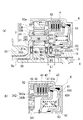
- FIG. 2 is a diagram illustrating a main part of the forward / reverse switching mechanism 2.
- FIG. 2A is a diagram illustrating the configuration of the planetary gear set 3.
- FIG. 2B is a diagram illustrating the vicinity of the forward clutch 4. Note that, in FIG. 2A, for convenience of description, illustration of the vicinity of the reverse brake 5 is omitted.
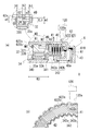
- FIG. 3 is a diagram illustrating a main part of the forward / reverse switching mechanism 2.
- FIG. 3A is an enlarged view of a main part for explaining the arrangement of the ring gear 32 of the planetary gear set 3 in the clutch drum 6.
- FIG. 3B is a sectional view taken along the line AA in FIG.
- the rotational driving force of the engine (not shown) is passed through the output shaft (rotation transmission shaft 9) of the torque converter (not shown) in the front-back direction. It is input to the progression switching mechanism 2.
- the forward / reverse switching mechanism 2 has a planetary gear set 3, a forward clutch 4, and a reverse brake 5.
- the forward clutch 4 when the forward clutch 4 is engaged, the rotation input from the torque converter side is output to the transmission mechanism section (not shown) side in forward rotation.
- the reverse brake 5 When the reverse brake 5 is engaged, the rotation input from the torque converter side is output in the reverse rotation to the transmission mechanism section side.
- the reverse brake 5 includes a driven plate 51 spline-fitted to the inner circumference of the support wall portion 101 on the transmission case 10 side, a drive plate 52 spline-fitted to the outer circumference of the circumferential wall portion 62 of the clutch drum 6, and a rotary shaft X. And a piston 53 that strokes in the direction.
- the driven plate 51 is provided on the support wall portion 101, which is a fixed member, so as to be movable in the rotation axis X direction while the rotation around the rotation axis X is restricted.
- the drive plate 52 is provided in the peripheral wall portion 62 so as to be movable in the rotation axis X direction in a state where the relative rotation with the clutch drum 6 in the circumferential direction around the rotation axis X is restricted.
- the driven plate 51 and the drive plate 52 are alternately arranged in the rotation axis X direction.
- the driven plate 51 and the drive plate 52 are arranged so that the inner diameter side of the driven plate 51 and the outer diameter side of the drive plate 52 overlap.
- a retaining plate 58 positioned by a snap ring 59 is provided on the side opposite to the piston 53 (on the right side in the figure) when viewed from the driven plate 51 and the drive plate 52.
- the pressing portion 53a of the piston 53 faces the area where the driven plate 51 and the drive plate 52 overlap with the wave spring 57 interposed therebetween.
- the transmission case 10 has a partition wall portion 102 that partitions the space for housing the forward / reverse switching mechanism 2 and the space for housing the transmission mechanism portion.
- An oil chamber R ⁇ b> 1 to which the working hydraulic pressure of the piston 53 is supplied is formed in a portion of the partition wall portion 102 facing the ring-shaped base portion 530 of the piston 53.
- the piston 53 When the hydraulic pressure is supplied to the oil chamber R1, the piston 53 is displaced in the direction away from the partition wall portion 102 (rightward in the figure) while compressing the spring Sp1 supported by the spring retainer 55. Then, the driven plate 51 and the drive plate 52 are pushed by the pushing portion 53a of the piston 53 and are displaced to the retaining plate 58 side. As a result, the driven plate 51 and the drive plate 52 are gripped between the pressing portion 53a and the retaining plate 58 with a pressure according to the hydraulic pressure. Then, when the driven plate 51 and the drive plate 52 are fastened relative to each other such that they cannot rotate relative to each other, the reverse brake 5 is put into a fastened state and the rotation of the clutch drum 6 is restricted. Furthermore, the ring gear 32, which is spline-fitted to the inner circumference of the peripheral wall portion 62 of the clutch drum 6, is also indirectly restricted in rotation.
- the forward clutch 4 includes a driven plate 41 spline-fitted to the inner circumference of the peripheral wall portion 62 of the clutch drum 6, a drive plate 42 spline-fitted to the outer circumference of a tubular support cylinder 342, and hydraulically in the rotational axis X direction. And a piston 43 that makes a stroke.
- the support cylinder 342 has a function as a so-called clutch hub.
- the driven plate 41 is provided in the peripheral wall portion 62 so as to be movable in the rotation axis X direction while the rotation around the rotation axis X is restricted.
- the drive plate 42 is provided so as to be movable in the rotation axis X direction in a state in which the relative rotation with the support cylinder 342 in the circumferential direction around the rotation axis X is restricted.
- the support cylinder 342 has spline peaks 342a and spline troughs 342b located on the outer diameter side alternately formed in the circumferential direction around the rotation axis X, and is integrated with a side plate 341 of the carrier 34 described later. Is formed (see (a) of FIG. 3).
- the drive plate 42 is spline-fitted to the outer periphery of the spline mountain portion 342a.
- the driven plates 41 and the drive plates 42 are alternately arranged in the rotation axis X direction.
- the driven plate 41 and the drive plate 42 are arranged so that the inner diameter side of the driven plate 41 and the outer diameter side of the drive plate 42 overlap.
- a retaining plate 48 positioned by a snap ring 49 is provided on the side opposite to the piston 43 (on the left side in the drawing) when viewed from the driven plate 41 and the drive plate 42.
- the pressing portion 43a of the piston 43 faces the overlapping area of the driven plate 51 and the drive plate 52 with the wave spring 47 interposed therebetween.
- the piston 43 is provided in a ring-shaped recess 610 provided in the bottom wall portion 61 of the clutch drum 6 so as to be movable back and forth in the direction of the rotation axis X.
- An oil chamber R2 to which the working hydraulic pressure of the piston 43 is supplied is formed in a portion of the bottom wall portion 61 facing the ring-shaped base portion 430 of the piston 43.
- the piston 43 When the working hydraulic pressure is supplied to the oil chamber R2, the piston 43 is displaced in the direction away from the bottom wall portion 61 (rightward in the figure) while compressing the spring Sp2 supported by the spring retainer 45. Then, the driven plate 41 and the drive plate 42 are pushed by the pushing portion 43a of the piston 43 and displaced to the retaining plate 48 side. As a result, the driven plate 41 and the drive plate 42 are gripped between the pressing portion 43a and the retaining plate 48 with a pressure according to the hydraulic pressure. Then, when the driven plate 41 and the drive plate 42 are fastened relative to each other such that they cannot rotate relative to each other, the forward clutch 4 is put into a fastened state.
- the support cylinder 342 into which the drive plate 42 is spline-fitted is integrally formed with the side plate portion 341 of the carrier 34 of the planetary gear set 3. Therefore, when the forward clutch 4 is engaged, the relative rotation between the clutch drum 6 and the carrier 34 of the planetary gear set 3 is restricted.
- the planetary gear set 3 includes a sun gear 31 that rotates integrally with the rotation transmission shaft 9 and a ring gear 32 that rotates integrally with the clutch drum 6.
- a pair of pinion gears 33A and 33B is located between 31 and the ring gear 32.
- the pinion gear 33A and the pinion gear 33B are provided by engaging the tooth portions provided on the outer periphery with each other.
- the pinion gear 33A meshes with the outer circumference of the sun gear 31, and the pinion gear 33B meshes with the inner circumference of the ring gear 32.
- the planetary gear set 3 is a double pinion type planetary gear mechanism. A single pinion type planetary gear mechanism may be used.
- the pinion gear 33A is supported by the pinion shaft 331 via a needle bearing NB. Both ends of the pinion shaft 331 are supported by the side plate portions 340 and 341 of the carrier 34.
- the pinion gear 33A supported by the pinion shaft 331 and the pinion gear 33B meshing with the pinion gear 33A rotate on their own axes. While revolving around the rotation axis X.
- the planetary gear set 3 is housed inside the clutch drum 6 together with the forward clutch 4 described above.
- the clutch drum 6 has a ring-shaped bottom wall portion 61 when viewed from the direction of the rotation axis X, and an outer peripheral wall portion that surrounds the outer periphery of the bottom wall portion 61 over the entire circumference. 62 and an inner peripheral wall portion 63 that surrounds the inner periphery of the bottom wall portion 61 over the entire circumference.
- the peripheral wall portion 62 has an opening 60 on the side opposite to the bottom wall portion 61 in the direction of the rotation axis X (left side in the drawing).
- the inner peripheral wall portion 63 has a cylindrical shape along the rotation axis X, and the peripheral wall portion 63 is provided on a cylindrical support wall portion 12 provided on the inner diameter side of the cover portion 11 and a transmission mechanism portion (not shown). Extrapolated from the side (left side in FIG. 2). In this state, the clutch drum 6 is supported by the support wall portion 12, which is a fixed member on the transmission case 10 side, in a state where rotation around the rotation axis X is allowed.
- a communication portion 64 that bypasses the support wall portion 12 and extends to the inner diameter side (rotation axis X side) is provided, and the inner diameter side of the communication portion 64 has a cylindrical shape.
- a support cylinder 65 is provided.
- the support cylinder 65 extends linearly from the inner peripheral end of the connecting portion 64 in the direction away from the sun gear 31 (rightward in the figure).
- the tip 65a of the support cylinder 65 extends to the inner diameter side of the support wall portion 12 and faces the tip end 15a of the cylindrical shaft 15 press-fitted into the inner periphery of the support wall portion 12 with a gap. ing.
- a needle bearing NB1 is provided between the outer circumference of the support cylinder 65 and the inner circumference of the peripheral wall portion 63.
- the needle bearing NB1 is interposed between the connecting portion 64 and the tip 12a of the support wall portion 12 in the direction of the rotation axis X, and blocks direct contact between the connecting portion 64 and the support wall portion 12.
- the support cylinder 65 is formed to have a predetermined length L1 in the rotation axis X direction, and the inner circumference of the support cylinder 65 is provided on the outer circumference of the rotation transmission shaft 9 via a bush BS (metal ring with low frictional resistance). It is supported.
- the bush BS is pressed into the inner circumference of the support cylinder 65 of the clutch drum 6.
- the clutch drum 6 having the support cylinder 65 is rotatably supported by the support wall portion 12 around the rotation axis X in a state where the inclination with respect to the rotation axis X is restricted by the support cylinder 65. Further, the clutch drum 6 is positioned in the radial direction by the bush BS supported by the rotation transmission shaft 9.
- the rotation transmission shaft 9 is the output shaft on the torque converter side (not shown).
- the rotation transmission shaft 9 is rotatably supported by a cylindrical shaft 15 press-fitted into the inner periphery of the support wall 12.
- the tip 9a side of the rotation transmission shaft 9 penetrates the inner diameter side of the support cylinder 65 in the rotation axis X direction.
- the sun gear 31 is integrally formed.
- the sun gear 31 of the rotation transmission shaft 9 projects outward in the radial direction of the rotation axis X from the outer periphery of the position away from the tip 9a toward the torque converter (right side in the drawing).
- a needle bearing NB2 is interposed between one side surface 31a of the sun gear 31 in the direction of the rotation axis X and the connecting portion 64 on the clutch drum 6 side.
- the tip 9a side of the rotation transmission shaft 9 is inserted inside a tubular connecting portion 343 provided on the inner diameter side of the carrier 34.
- a bush BS is provided between the outer circumference of the rotation transmitting shaft 9 and the inner circumference of the connecting portion 343, and the connecting portion 343 of the carrier 34 is supported by the rotation transmitting shaft 9 via the bush BS. .
- the connection portion 343 of the carrier 34 and the rotation transmission shaft 9 are relatively rotatable around the rotation axis X.
- the side plate portion 340 of the carrier 34 extends radially outward from the end portion of the coupling portion 343 on the torque converter side, and the tip end 81a of the input shaft 81 on the speed change mechanism portion side is formed on the side plate portion 340 in the rotation axis X direction. Has been struck by. In this state, the inner circumference of the input shaft 81 and the outer circumference of the connecting portion 343 are spline-fitted, and the connecting portion 343 of the carrier 34 and the input shaft 81 on the side of the speed change mechanism are connected so as not to rotate relative to each other. Has been done.
- the sun gear 31 is an input unit to which rotation is input from the torque converter side
- the carrier 34 is an output unit to output rotation to the transmission mechanism unit side.
- the input section and the output section are reversed.
- a portion of the planetary gear set 3 that is neither an input unit nor an output unit is referred to as a “floating member”.
- the ring gear 32 corresponds to the “floating member”.
- the ring gear 32 of the planetary gear set 3 is spline-fitted to the inner circumference of the outer peripheral wall portion 62 of the clutch drum 6.
- the peripheral wall portion 62 on the outer diameter side of the clutch drum 6 includes a small diameter portion 621 on the bottom wall portion 61 side and a large diameter portion 622 larger in diameter than the small diameter portion 621.
- the area of the large diameter portion 622 is formed by spline peak portions 622a and spline valley portions 622b being alternately arranged in the circumferential direction around the rotation axis X.
- the spline peak portion 622a and the spline valley portion 622b are formed in a range from the tip 62a of the peripheral wall portion 62 to the connection portion with the small diameter portion 621. In the large diameter portion 622, the spline peak portion 622a and the spline valley portion 622b are provided (extended) over the entire length in the rotation axis X direction.
- the spline peak portion 622a and the spline valley portion 622b are provided over the entire length of the large diameter portion 622 in the longitudinal direction (rotation axis X direction).
- no component on the reverse brake 5 side is located on the outer periphery of the area on the small diameter portion 621 side of the large diameter portion 622.
- the spline peak portion 622a and the spline valley portion 622b are alternately arranged in the circumferential direction around the rotation axis. Therefore, the outer circumference of the area of the large diameter portion 622 on the small diameter portion 621 side can be used as the sensor area (detected portion) of the rotation speed sensor 120.
- a spline mountain portion 622a is formed on the extension of the sensor surface 120a of the rotation speed sensor 120.
- the spline trough portion 622b is positioned. Then, the rotation speed sensor 120 can output a pulse signal including an ON signal and an OFF signal corresponding to the spline peak portion 622a and the spline valley portion 622b to a control device (not shown).
- the region where the rotational speed sensor 120 is provided divides the region where the forward / reverse switching mechanism 2 is provided in the transmission case 10 and the region where the oil pump is provided from the support wall portion 101 ( (See FIG. 1). Therefore, there is an opening in which the rotation speed sensor 120 can be provided, so that the rotation speed sensor 120 can be installed without changing the shape of the transmission case 10 or changing the layout inside the transmission case 10. It has become.
- the large diameter portion 622 of the peripheral wall portion 62 is provided across the radial direction outer side of the forward clutch 4 and the ring gear 32 of the planetary gear set 3 in the rotation axis X direction.
- the drive plate 52 of the reverse brake 5 (see FIG. 1) described above is spline-fitted to the outer periphery of the peripheral wall portion 62 on the side of the tip 62a.
- the ring gear 32 is provided on the inner diameter side of an area in which the driven plate 51 and the drive plate 52 of the reverse brake 5 are alternately arranged.
- the ring gear 32 has a ring-shaped base 320 having teeth 32a on the inner circumference and a spline fitting portion 321 protruding radially outward from the outer circumference of the base 320. is doing.
- the ring gear 32 is an internal gear, and the portion where the outer peripheral surface (the surface on the back side of the tooth surface) of the internal gear is formed is supported by two snap rings (first snap ring 38 and second snap ring 39). Has been done.
- the spline fitting portion 321 projects radially outward from the outer circumference on the one end side (opening 60 side) in the rotation axis X direction.
- the spline fitting portion 321 is provided for fitting the ring gear 32 to the inner circumference of the large diameter portion 622 on the clutch drum 6 side.
- the width W1 of the spline fitting portion 321 in the rotation axis direction is formed to be shorter than the width W2 of the base portion 320 in the rotation axis X direction, and these widths W1 and W2 are the side plate portions 340 and 341 of the carrier 34. Is narrower than the width W3 of.
- the first snap ring 38 and the second snap ring 39 are fitted and fixed on both sides of the spline fitting portion 321 of the ring gear 32.
- the first snap ring 38 and the second snap ring 39 are provided for positioning the ring gear 32 in the rotation axis X direction.
- the first snap ring 38 and the second snap ring 39 are respectively engaged with the grooves M1 and M2 provided in the peripheral wall portion 62, and the thickness of the first snap ring 38 and the second snap ring 39 in the rotation axis X direction.
- the b1 and b2 have a thickness that matches the thickness of the grooves M1 and M2 in the rotation axis direction.
- the first snap ring 38 is provided so as to be displaced in the rotational axis X direction from the radially outer region of the ring gear 32, and the first snap ring 38 is provided in the radial direction with respect to the ring gear 32. It does not overlap.
- the first snap ring 38 is provided to prevent the ring gear 32 from coming off from the opening of the bottomed cylindrical clutch drum 6.
- the second snap ring 39 is positioned in a region radially outside the ring gear 32, and the second snap ring 39 overlaps the ring gear 32 in the radial direction.
- the second snap ring 39 is provided to prevent the ring gear 32 from moving toward the bottom wall portion 61 side of the clutch drum 6.
- the ring gear 32 is provided while being positioned by the second snap ring 39 while avoiding interference with the snap ring 49 (third snap ring) of the forward clutch 4 described above. Therefore, a gap in the rotation axis direction is left between the ring gear 32 and the snap ring 49.
- the radial length a1 of the first snap ring 38 is larger than the radial length a2 of the second snap ring 39. This is because the second snap ring 39 is arranged so as to overlap the ring gear 32 in the radial direction, so that the gap between the outer periphery of the base portion 320 of the ring gear 32 and the inner periphery of the peripheral wall portion 62 (spline valley portion 622b). This is because the length needs to be accommodated in CL1.
- the second snap ring 39 does not need to be provided so as to be displaced in the rotational axis X direction from the radially outer region of the ring gear 32, and therefore the large size of the peripheral wall portion 62 of the clutch drum 6 in the rotational axis X direction. Can be prevented.
- the thickness b1 of the first snap ring 38 in the rotation axis X direction is different from the thickness b2 of the second snap ring 39 in the rotation axis X direction. This is so that the first snap ring 38 and the second snap ring 39 can be distinguished.
- the thickness b1 of the first snap ring 38 in the rotation axis X direction is smaller than the thickness b2 of the second snap ring 39 in the axial direction. If the thickness b1 of the first snap ring 38 in the direction of the rotation axis X is large, a space that does not contribute to the arrangement of parts such as the planetary gear set 3 is left on the opening 60 side of the peripheral wall portion 62. If such a space is left, the size of the peripheral wall portion 62 of the clutch drum 6 in the rotation axis X direction becomes large, which is not preferable.
- the second snap ring 39 is located on the bottom wall 61 side (back side) of the first snap ring 38.
- the first snap ring 38 is arranged closer to the opening 60 than the second snap ring 39.
- the snap ring 49 (third snap ring) of the forward clutch 4 is provided on the bottom wall portion 61 side (back side) of the clutch drum 6 as viewed from the second snap ring 39.
- the snap ring 49 is provided with a space between the second snap ring 39 and the ring gear 32.
- the second snap ring 39 is located between the first snap ring 38 and the snap ring 49 in the rotation axis X direction.
- the second snap ring 39 has a flatter cross section than the first snap ring 38 and has a small radial length a2. Therefore, the ring gear 32 may tilt toward the forward clutch 4 side. In such a case, the snap ring 49 close to the second snap ring 39 can prevent the ring gear 32 from tilting. Further, the spline fitting portion 321 of the ring gear 32 is located between the first snap ring 38 and the second snap ring 39, and the ring gear 32 is arranged with a slight play. Therefore, when the sun gear 31 and the carrier 34 are tilted with respect to the rotation axis X, the ring gear 32 can be self-centering.
- the ring gear 32 is set as a floating member, and the ring gear 32 is fixed to the peripheral wall portion 62 of the clutch drum 6 (drum member). This eliminates the need to newly provide a support member for the ring gear 32, which is a floating member.
- the peripheral wall portion 62 is commonly used for fixing and supporting the two parts. This makes it possible to reduce the number of parts as compared with the case where dedicated parts are provided and fixed / supported. This can be expected to reduce the manufacturing cost of the continuously variable transmission 1.
- a large diameter portion 622 having a spline peak portion 622a and a spline valley portion 622b is provided in a range in the rotation axis X direction that straddles the reverse brake 5 and the forward clutch 4.
- the spline peak portion 622a and the spline valley portion 622b in the area on the outer diameter side of the area where the forward clutch 4 is provided can be used as the detection surface of the rotation speed sensor 120. Therefore, the manufacturing cost of the continuously variable transmission 1 can be reduced as compared with the case where a dedicated detection surface is prepared.
- the support structure of the ring gear 32 (gear) has the following configuration.
- the support structure is A clutch drum 6 (support member) that fits with a ring gear 32 (gear) of the planetary gear set 3; It has a first snap ring 38 and a second snap ring 39 that are attached to the peripheral wall portion 62 of the clutch drum 6 and that support the ring gear 32.
- the first snap ring 38 does not overlap the ring gear 32 in the radial direction.
- the second snap ring 39 overlaps the ring gear 32 in the radial direction.
- the radial length a1 of the first snap ring 38 is larger than the radial length a2 of the second snap ring 39.
- the second snap ring 39 has a supporting capacity equivalent to that of the related art, while the first snap ring 38 is longer in the radial direction than the second snap ring 39, and thus has a supporting capacity higher than that of the related art. .
- the total support capacity can be improved.
- the present support structure has the axial length direction (rotation axis X direction). There is an advantage in that it can be shortened. Accordingly, the first snap ring 38 and the second snap ring 39 can appropriately support the ring gear 32 (gear) while suppressing the axial length of the ring gear 32 (gear) in the rotation axis X direction.
- the support structure of the ring gear 32 (gear) has the following configuration. (2) The thickness b1 of the first snap ring 38 in the rotation axis X direction is different from the thickness b2 of the second snap ring 39 in the rotation axis direction.
- the first snap ring 38 and the second snap ring 39 are attached to the inner circumference of the peripheral wall portion 62 with the side surfaces in the rotation axis X direction sandwiched by fingers.
- By changing the thicknesses b1 and b2 of the first snap ring 38 and the second snap ring 39 in the direction of the rotation axis X it is possible to prevent misselection (misassembly) of the snap ring during mounting.
- the first snap ring 38 is attached after the second snap ring 39 is attached.
- the support structure of the ring gear 32 (gear) has the following configuration.
- the clutch drum 6 (support member) has an opening 60 that opens in the direction of the rotation axis X, and a bottom wall 61 (bottom) on the back side when viewed from the opening 60.
- the first snap ring 38 is arranged closer to the opening 60 than the second snap ring 39 is.
- the support structure of the ring gear 32 (gear) has the following configuration.
- the clutch drum 6 (support member) has an opening 60 that opens in the direction of the rotation axis X, and a bottom wall 61 (bottom) on the back side when viewed from the opening 60.
- the first snap ring 38 is arranged closer to the opening 60 than the second snap ring 39 is.
- the thickness b2 of the second snap ring 39 in the rotation axis X direction is larger than the thickness b1 of the first snap ring 38 in the rotation axis X direction.
- the components are attached in order from the bottom wall portion 61 side. Therefore, by making the thickness b2 of the second snap ring 39 that is attached first larger than the thickness b1 of the first snap ring 38 that is attached later, it is possible to reliably prevent misassembly. Furthermore, it is possible to suppress an increase in the total axial length.
- the first snap ring 38 that is longer in the radial direction than the second snap ring 39 is attached when the second snap ring 39 should be attached, the first snap ring 38 interferes with the ring gear 32.
- the ring gear 32 cannot be assembled. Therefore, since it is impossible to assemble the ring gear 32, it can be understood that the first spring is erroneously assembled at the place where the second snap ring 39 should be attached.
- the axial length b2 of the second snap ring 39 is longer than the axial length b1 of the first snap ring 38 and longer than the axial length of the groove M1 in which the first snap ring 38 is mounted. . Therefore, even after the second snap ring 39 and the ring gear 32 are properly attached, the second snap ring 39 is attached even if the second snap ring 39 is attached to the groove M1 in which the first snap ring 38 should be attached. I can't. Therefore, since it is impossible to attach the second snap ring 39 to the groove M1, it can be understood that the second snap ring 39 is erroneously attached to the place where the first snap ring 38 should be attached. As a result, it is possible to reliably prevent erroneous assembly.
- the support structure of the ring gear 32 (gear) has the following configuration. (5) A snap ring 49 (third snap ring) for supporting the retaining plate 48 (plate) fitted to the clutch drum 6 (support member) is provided. The second snap ring 39 is located between the first snap ring 38 and the snap ring 49 (third snap ring). The snap ring 49 (third snap ring) is arranged apart from the ring gear 32 (gear).
- the support structure of the ring gear 32 (gear) has the following configuration. (6)
- the radial length a3 of the snap ring 49 (third snap ring) is larger than the radial length a2 of the second snap ring 39.
- the snap ring 49 (third snap ring) is arranged at a position adjacent to the ring gear 32 (gear).
- the snap rings 49 are normally arranged apart from each other so as not to adversely affect the ring gear 32, but they are arranged at a close position, that is, an adjacent position.
- a close position that is, an adjacent position.
- the ring gear 32 and the snap ring 49 are always in contact with each other, when the ring gear 32 receives the pushing force of the piston 43 (clutch piston), the ring gear 32 is relatively moved with respect to the sun gear 31 and the pinion gears 33A and 33B. The amount of eccentricity increases. If so, gear noise may occur, but since the snap ring 49 is separated from the ring gear 32, the generation of gear noise can be preferably prevented.
- the case where the support member is the clutch drum 6 has been illustrated, but other support members (fixed members) such as a transmission case may be used.
- the case where the gear is the ring gear 32 of the planetary gear set 3 has been described as an example, but the present invention can be applied to any gear as long as it is a gear.
Landscapes
- Engineering & Computer Science (AREA)
- General Engineering & Computer Science (AREA)
- Mechanical Engineering (AREA)
- General Details Of Gearings (AREA)
- Gears, Cams (AREA)
- Hydraulic Clutches, Magnetic Clutches, Fluid Clutches, And Fluid Joints (AREA)
Abstract
リングギア(32)の支持構造は、リングギア(32)とスプライン嵌合するクラッチドラム(6)と、クラッチドラム(6)の周壁部(62)に取り付けられて、リングギア(32)を支持する第1スナップリング(38)及び第2スナップリング(39)と、を有する。第1スナップリング(38)は、リングギア(32)と径方向においてオーバーラップしない。第2スナップリング(39)は、リングギア(32)と径方向においてオーバーラップする。第1スナップリング(38)の径方向の長さ(a1)は、第2スナップリング(39)の径方向の長さa2よりも大きい。
Description
本発明は、歯車の支持構造に関する。
特許文献1には、リングギア(歯車)の支持構造として、リングギアをドラムと嵌合可能な形状とし、2つのスナップリングでリングギアを支持する構造が開示されている。
この構造では、2つのスナップリングを用いることでガタが形成されるので、サンギアやキャリアの倒れに対して自動調心することが可能となる。
この構造では、2つのスナップリングを用いることでガタが形成されるので、サンギアやキャリアの倒れに対して自動調心することが可能となる。
特許文献1の構造においてはリングギアに2つの切欠きを設け、当該切欠きと径方向にオーバーラップする位置にスナップリングを配置しており、スナップリングの径方向における長さが短くなっている。
しかしながら、リングギアの脱落を防止するという意味においてはスナップリングの径方向における長さは極力長い方が好ましい。
そこで、遊星歯車組の回転軸方向の軸長を抑えつつリングギアを適切に支持することが求められている。
本発明は、リングギアをはじめとする歯車の軸長を抑えつつ適切に支持することを目的とするものである。
しかしながら、リングギアの脱落を防止するという意味においてはスナップリングの径方向における長さは極力長い方が好ましい。
そこで、遊星歯車組の回転軸方向の軸長を抑えつつリングギアを適切に支持することが求められている。
本発明は、リングギアをはじめとする歯車の軸長を抑えつつ適切に支持することを目的とするものである。
本発明は、
歯車と嵌合する支持部材と、
前記支持部材に取り付けられ、且つ、前記歯車を支持する第1スナップリング及び第2スナップリングと、を有し、
前記第1スナップリングは、前記歯車と径方向においてオーバーラップせず、
前記第2スナップリングは、前記歯車と径方向においてオーバーラップし、
前記第1スナップリングの径方向の長さは、前記第2スナップリングの径方向の長さよりも大きい構成の歯車の支持構造とした。
歯車と嵌合する支持部材と、
前記支持部材に取り付けられ、且つ、前記歯車を支持する第1スナップリング及び第2スナップリングと、を有し、
前記第1スナップリングは、前記歯車と径方向においてオーバーラップせず、
前記第2スナップリングは、前記歯車と径方向においてオーバーラップし、
前記第1スナップリングの径方向の長さは、前記第2スナップリングの径方向の長さよりも大きい構成の歯車の支持構造とした。
本発明によれば、
第2スナップリングは従来相当の支持能力を有する一方、第1スナップリングは従来よりも高い支持能力を有するのでトータルとしての支持能力を向上することができる。
両方のスナップリングを歯車と径方向においてオーバーラップしないようにする場合と比較すると、本支持構造は軸長方向を短縮できる点でメリットがある。
これにより、第1スナップリングと第2スナップリングにより、歯車の回転軸方向の軸長を抑えつつ歯車を適切に支持できる。
第2スナップリングは従来相当の支持能力を有する一方、第1スナップリングは従来よりも高い支持能力を有するのでトータルとしての支持能力を向上することができる。
両方のスナップリングを歯車と径方向においてオーバーラップしないようにする場合と比較すると、本支持構造は軸長方向を短縮できる点でメリットがある。
これにより、第1スナップリングと第2スナップリングにより、歯車の回転軸方向の軸長を抑えつつ歯車を適切に支持できる。
以下、本発明の実施形態を、車両用のベルト式の無段変速機1の前後進切替機構2が備える遊星歯車機構のリングギアの場合を例に挙げて説明する。
図1は、ベルト式の無段変速機1が備える前後進切替機構2周りを説明する図である。
図2は、前後進切替機構2の主要部を説明する図である。図2の(a)は、遊星歯車組3の構成を説明する図である。図2の(b)は、前進クラッチ4周りを説明する図である。なお、図2の(a)では、説明の便宜上、後進ブレーキ5周りの図示を省略している。
図3は、前後進切替機構2の主要部を説明する図である。図3の(a)は、クラッチドラム6における遊星歯車組3のリングギア32の配置を説明する要部拡大図である。図3の(b)は、(a)におけるA-A断面図である。
図2は、前後進切替機構2の主要部を説明する図である。図2の(a)は、遊星歯車組3の構成を説明する図である。図2の(b)は、前進クラッチ4周りを説明する図である。なお、図2の(a)では、説明の便宜上、後進ブレーキ5周りの図示を省略している。
図3は、前後進切替機構2の主要部を説明する図である。図3の(a)は、クラッチドラム6における遊星歯車組3のリングギア32の配置を説明する要部拡大図である。図3の(b)は、(a)におけるA-A断面図である。
図1に示すように、ベルト式の無段変速機1では、エンジン(図示せず)の回転駆動力が、トルクコンバータ(図示せず)の出力軸(回転伝達軸9)を介して、前後進切替機構2に入力される。
前後進切替機構2は、遊星歯車組3と、前進クラッチ4と、後進ブレーキ5と、を有している。
前後進切替機構2では、前進クラッチ4が締結されると、トルクコンバータ側から入力された回転が、順回転で変速機構部(図示せず)側に出力される。後進ブレーキ5が締結されると、トルクコンバータ側から入力された回転が、逆回転で変速機構部側に出力される。
前後進切替機構2は、遊星歯車組3と、前進クラッチ4と、後進ブレーキ5と、を有している。
前後進切替機構2では、前進クラッチ4が締結されると、トルクコンバータ側から入力された回転が、順回転で変速機構部(図示せず)側に出力される。後進ブレーキ5が締結されると、トルクコンバータ側から入力された回転が、逆回転で変速機構部側に出力される。
[後進ブレーキ]
後進ブレーキ5は、変速機ケース10側の支持壁部101の内周にスプライン嵌合したドリブンプレート51と、クラッチドラム6の周壁部62の外周にスプライン嵌合したドライブプレート52と、回転軸X方向にストロークするピストン53と、を有している。
後進ブレーキ5は、変速機ケース10側の支持壁部101の内周にスプライン嵌合したドリブンプレート51と、クラッチドラム6の周壁部62の外周にスプライン嵌合したドライブプレート52と、回転軸X方向にストロークするピストン53と、を有している。
固定側の部材である支持壁部101においてドリブンプレート51は、回転軸X回りの回転が規制された状態で、回転軸X方向に移動可能に設けられている。
周壁部62においてドライブプレート52は、回転軸X周りの周方向におけるクラッチドラム6との相対回転が規制された状態で、回転軸X方向に移動可能に設けられている。
周壁部62においてドライブプレート52は、回転軸X周りの周方向におけるクラッチドラム6との相対回転が規制された状態で、回転軸X方向に移動可能に設けられている。
ドリブンプレート51とドライブプレート52は、回転軸X方向で交互に配置されている。ドリブンプレート51とドライブプレート52は、ドリブンプレート51の内径側とドライブプレート52の外径側とが重なるように配置されている。
ドリブンプレート51とドライブプレート52とから見て、ピストン53とは反対側(図中、右側)には、スナップリング59で位置決めされたリテーニングプレート58が設けられている。
ピストン53の押圧部53aは、ドリブンプレート51とドライブプレート52の重なる領域に、ウェーブスプリング57を間に挟んで対向している。
ピストン53の押圧部53aは、ドリブンプレート51とドライブプレート52の重なる領域に、ウェーブスプリング57を間に挟んで対向している。
変速機ケース10は、前後進切替機構2を収容する空間と、変速機構部を収容する空間とを仕切る仕切壁部102を有している。この仕切壁部102におけるピストン53のリング状の基部530との対向部には、ピストン53の作動油圧が供給される油室R1が形成されている。
この油室R1に作動油圧が供給されると、ピストン53が、スプリングリテーナ55で支持されたスプリングSp1を圧縮しながら、仕切壁部102から離れる方向(図中、右方向)に変位する。
そうすると、ドリブンプレート51とドライブプレート52とが、ピストン53の押圧部53aにより押されて、リテーニングプレート58側に変位する。
これにより、ドリブンプレート51とドライブプレート52とが、作動油圧に応じた圧力で、押圧部53aとリテーニングプレート58との間で把持される。
そして、ドリブンプレート51とドライブプレート52が相対回転不能に締結されると、後進ブレーキ5が締結状態になって、クラッチドラム6の回転が規制される。さらに、クラッチドラム6の周壁部62の内周にスプライン嵌合したリングギア32もまた、間接的に回転が規制される。
そうすると、ドリブンプレート51とドライブプレート52とが、ピストン53の押圧部53aにより押されて、リテーニングプレート58側に変位する。
これにより、ドリブンプレート51とドライブプレート52とが、作動油圧に応じた圧力で、押圧部53aとリテーニングプレート58との間で把持される。
そして、ドリブンプレート51とドライブプレート52が相対回転不能に締結されると、後進ブレーキ5が締結状態になって、クラッチドラム6の回転が規制される。さらに、クラッチドラム6の周壁部62の内周にスプライン嵌合したリングギア32もまた、間接的に回転が規制される。
[前進クラッチ]
前進クラッチ4は、クラッチドラム6の周壁部62の内周にスプライン嵌合したドリブンプレート41と、筒状の支持筒342の外周にスプライン嵌合したドライブプレート42と、油圧により回転軸X方向にストロークするピストン43と、を有している。
支持筒342は、いわゆるクラッチハブとしての機能を有する。
前進クラッチ4は、クラッチドラム6の周壁部62の内周にスプライン嵌合したドリブンプレート41と、筒状の支持筒342の外周にスプライン嵌合したドライブプレート42と、油圧により回転軸X方向にストロークするピストン43と、を有している。
支持筒342は、いわゆるクラッチハブとしての機能を有する。
図2の(b)に示すように、周壁部62においてドリブンプレート41は、回転軸X回りの回転が規制された状態で、回転軸X方向に移動可能に設けられている。
支持筒342においてドライブプレート42は、回転軸X周りの周方向における支持筒342との相対回転が規制された状態で、回転軸X方向に移動可能に設けられている。
支持筒342においてドライブプレート42は、回転軸X周りの周方向における支持筒342との相対回転が規制された状態で、回転軸X方向に移動可能に設けられている。
支持筒342は、外径側に位置するスプライン山部342aとスプライン谷部342bとが、回転軸X周りの周方向に交互に連なって形成されており、後記するキャリア34の側板部341と一体に形成されている(図3の(a)参照)。
支持筒342では、スプライン山部342aの外周に、ドライブプレート42がスプライン嵌合している。
支持筒342では、スプライン山部342aの外周に、ドライブプレート42がスプライン嵌合している。
図2に示すように、ドリブンプレート41とドライブプレート42は、回転軸X方向で交互に配置されている。ドリブンプレート41とドライブプレート42は、ドリブンプレート41の内径側とドライブプレート42の外径側とが重なるように配置されている。
ドリブンプレート41とドライブプレート42とから見て、ピストン43とは反対側(図中、左側)には、スナップリング49で位置決めされたリテーニングプレート48が設けられている。
ピストン43の押圧部43aは、ドリブンプレート51とドライブプレート52の重なる領域に、ウェーブスプリング47を間に挟んで対向している。
ピストン43の押圧部43aは、ドリブンプレート51とドライブプレート52の重なる領域に、ウェーブスプリング47を間に挟んで対向している。
ピストン43は、クラッチドラム6の底壁部61に設けたリング状の凹部610内で、回転軸X方向に進退移動可能に設けられている。
底壁部61におけるピストン43のリング状の基部430との対向部には、ピストン43の作動油圧が供給される油室R2が形成されている。
底壁部61におけるピストン43のリング状の基部430との対向部には、ピストン43の作動油圧が供給される油室R2が形成されている。
この油室R2に作動油圧が供給されると、ピストン43が、スプリングリテーナ45で支持されたスプリングSp2を圧縮しながら、底壁部61から離れる方向(図中、右方向)に変位する。
そうすると、ドリブンプレート41とドライブプレート42とが、ピストン43の押圧部43aにより押されて、リテーニングプレート48側に変位する。
これにより、ドリブンプレート41とドライブプレート42とが、作動油圧に応じた圧力で、押圧部43aとリテーニングプレート48との間で把持される。
そして、ドリブンプレート41とドライブプレート42が相対回転不能に締結されると、前進クラッチ4が締結状態になる。
ここで、ドライブプレート42がスプライン嵌合する支持筒342は、遊星歯車組3のキャリア34の側板部341と一体に形成されている。
そのため、前進クラッチ4が締結状態になると、クラッチドラム6と、遊星歯車組3のキャリア34との相対回転が規制される。
そうすると、ドリブンプレート41とドライブプレート42とが、ピストン43の押圧部43aにより押されて、リテーニングプレート48側に変位する。
これにより、ドリブンプレート41とドライブプレート42とが、作動油圧に応じた圧力で、押圧部43aとリテーニングプレート48との間で把持される。
そして、ドリブンプレート41とドライブプレート42が相対回転不能に締結されると、前進クラッチ4が締結状態になる。
ここで、ドライブプレート42がスプライン嵌合する支持筒342は、遊星歯車組3のキャリア34の側板部341と一体に形成されている。
そのため、前進クラッチ4が締結状態になると、クラッチドラム6と、遊星歯車組3のキャリア34との相対回転が規制される。
[遊星歯車組]
図2の(a)に示すように、遊星歯車組3は、回転伝達軸9と一体に回転するサンギア31と、クラッチドラム6と一体に回転するリングギア32と、を有しており、サンギア31とリングギア32との間には、一対のピニオンギア33A、33Bが位置している。
図2の(a)に示すように、遊星歯車組3は、回転伝達軸9と一体に回転するサンギア31と、クラッチドラム6と一体に回転するリングギア32と、を有しており、サンギア31とリングギア32との間には、一対のピニオンギア33A、33Bが位置している。
ピニオンギア33Aとピニオンギア33Bは、外周に設けた歯部同士を互い噛合させて設けられている。ピニオンギア33Aは、サンギア31の外周に噛合していると共に、ピニオンギア33Bは、リングギア32の内周に噛合している。遊星歯車組3は、ダブルピニオン式の遊星歯車機構である。なお、シングルピニオン式の遊星歯車機構であっても良い。
ピニオンギア33Aは、ニードルベアリングNBを介して、ピニオン軸331で支持されている。ピニオン軸331の両端は、キャリア34の側板部340、341で支持されている。
遊星歯車組3では、サンギア31および/またはリングギア32が回転軸X回りに回転すると、ピニオン軸331で支持されたピニオンギア33Aと、このピニオンギア33Aに噛合するピニオンギア33Bとが、自転しながら回転軸X周りに公転する。
遊星歯車組3では、サンギア31および/またはリングギア32が回転軸X回りに回転すると、ピニオン軸331で支持されたピニオンギア33Aと、このピニオンギア33Aに噛合するピニオンギア33Bとが、自転しながら回転軸X周りに公転する。
図1に示すように、変速機ケース10の内部において遊星歯車組3は、前記した前進クラッチ4と共に、クラッチドラム6の内部に収容されている。
図2の(a)に示すように、クラッチドラム6は、回転軸X方向から見てリング状を成す底壁部61と、底壁部61の外周を全周に亘って囲む外側の周壁部62と、底壁部61の内周を全周に亘って囲む内側の周壁部63と、を有している。
周壁部62は、回転軸X方向における底壁部61とは反対側(図中、左側)が、開口部60となっている。
周壁部62は、回転軸X方向における底壁部61とは反対側(図中、左側)が、開口部60となっている。
内側の周壁部63は、回転軸Xに沿う円筒状を成しており、この周壁部63は、カバー部11の内径側に設けられた筒状の支持壁部12に、図示しない変速機構部側(図2における左側)から外挿されている。
この状態においてクラッチドラム6は、変速機ケース10側の固定部材である支持壁部12で、回転軸X回りの回転が許容された状態で支持されている。
この状態においてクラッチドラム6は、変速機ケース10側の固定部材である支持壁部12で、回転軸X回りの回転が許容された状態で支持されている。
内側の周壁部63の先端には、支持壁部12を迂回して内径側(回転軸X側)に延びる連絡部64が設けられており、この連絡部64の内径側には、円筒状の支持筒65が設けられている。
支持筒65は、連絡部64の内周端から、サンギア31から離れる方向(図中、右方向)に直線状に延びている。支持筒65の先端65aは、支持壁部12の内径側に及んでいると共に、支持壁部12の内周に圧入された円筒状のシャフト15の先端15aとの間に隙間を空けて対向している。
支持筒65の外周と周壁部63の内周との間には、ニードルベアリングNB1が設けられている。回転軸X方向においてニードルベアリングNB1は、連絡部64と、支持壁部12の先端12aとの間に介在しており、連絡部64と支持壁部12との直接の接触を阻止している。
支持筒65は、回転軸X方向に所定長さL1を持って形成されており、支持筒65の内周は、回転伝達軸9の外周にブッシュBS(摩擦抵抗が少ない金属リング)を介して支持されている。ブッシュBSは、クラッチドラム6の支持筒65の内周に圧入されている。この状態において支持筒65を持つクラッチドラム6は、回転軸Xに対する傾きが支持筒65により規制された状態で、支持壁部12で回転軸X回りに回転可能に支持されている。
さらに、クラッチドラム6の径方向の位置決めが、回転伝達軸9で支持されたブッシュBSでされている。
さらに、クラッチドラム6の径方向の位置決めが、回転伝達軸9で支持されたブッシュBSでされている。
前記したように回転伝達軸9は、図示しないトルクコンバータ側の出力軸である。回転伝達軸9は、支持壁部12の内周に圧入された円筒状のシャフト15で、回転可能に支持されている。
回転伝達軸9の先端9a側は、支持筒65の内径側を回転軸X方向に貫通しており、回転伝達軸9の先端9a側では、支持筒65との干渉を避けた位置の外周に、サンギア31が一体に形成されている。
回転伝達軸9の先端9a側は、支持筒65の内径側を回転軸X方向に貫通しており、回転伝達軸9の先端9a側では、支持筒65との干渉を避けた位置の外周に、サンギア31が一体に形成されている。
回転伝達軸9においてサンギア31は、先端9aからトルクコンバータ側(図中、右側)に離れた位置の外周から、回転軸Xの径方向外側に突出している。
回転軸X方向におけるサンギア31の一方の側面31aと、クラッチドラム6側の連絡部64との間には、ニードルベアリングNB2が介在している。
回転伝達軸9の先端9a側は、キャリア34の内径側に設けた筒状の連結部343の内側に挿入されている。
回転軸X方向におけるサンギア31の一方の側面31aと、クラッチドラム6側の連絡部64との間には、ニードルベアリングNB2が介在している。
回転伝達軸9の先端9a側は、キャリア34の内径側に設けた筒状の連結部343の内側に挿入されている。
回転伝達軸9の外周と、連結部343の内周との間には、ブッシュBSが設けられており、キャリア34の連結部343は、ブッシュBSを介して回転伝達軸9で支持されている。キャリア34の連結部343と回転伝達軸9は、回転軸X回りに相対回転可能である。
キャリア34の側板部340は、連結部343のトルクコンバータ側の端部から径方向外側に延びており、側板部340には、変速機構部側の入力軸81の先端81aが、回転軸X方向から突き当てられている。
この状態において、入力軸81の内周と、連結部343の外周とがスプライン嵌合しており、キャリア34の連結部343と、変速機構部側の入力軸81とが、相対回転不能に連結されている。
この状態において、入力軸81の内周と、連結部343の外周とがスプライン嵌合しており、キャリア34の連結部343と、変速機構部側の入力軸81とが、相対回転不能に連結されている。
遊星歯車組3では、サンギア31が、トルクコンバータ側から回転が入力される入力部であり、キャリア34が、変速機構部側に回転を出力する出力部である。なお、無段変速機1を搭載した車両の被牽引走行時には、入力部と出力部とが逆になる。
なお、本明細書では、遊星歯車組3における入力部でも出力部でもない箇所を、「浮遊部材」と呼ぶ。本実施形態では、リングギア32が「浮遊部材」に相当する。
なお、本明細書では、遊星歯車組3における入力部でも出力部でもない箇所を、「浮遊部材」と呼ぶ。本実施形態では、リングギア32が「浮遊部材」に相当する。
遊星歯車組3のリングギア32は、クラッチドラム6の外径側の周壁部62の内周にスプライン嵌合している。
図3の(a)に示すように、クラッチドラム6の外径側の周壁部62は、底壁部61側の小径部621と、小径部621よりも大径の大径部622と、を有している。
周壁部62では、大径部622の領域が、スプライン山部622aとスプライン谷部622bとが、回転軸X周りの周方向に交互に連なって形成されている。
図3の(a)に示すように、クラッチドラム6の外径側の周壁部62は、底壁部61側の小径部621と、小径部621よりも大径の大径部622と、を有している。
周壁部62では、大径部622の領域が、スプライン山部622aとスプライン谷部622bとが、回転軸X周りの周方向に交互に連なって形成されている。
これらスプライン山部622aとスプライン谷部622bは、周壁部62の先端62aから、小径部621との接続部までの範囲に形成されている。
大径部622においてスプライン山部622aとスプライン谷部622bは、回転軸X方向の全長に亘って設けられている(延在している)。
大径部622においてスプライン山部622aとスプライン谷部622bは、回転軸X方向の全長に亘って設けられている(延在している)。
クラッチドラム6の周壁部62では、スプライン山部622aとスプライン谷部622bが、大径部622の長手方向(回転軸X方向)の全長に亘って設けられている。
ここで、大径部622における小径部621側の領域の外周には、後進ブレーキ5側の部品が位置していない。そして、大径部622では、スプライン山部622aとスプライン谷部622bとが、回転軸周りの周方向に交互に配置されている。そのため、大径部622における小径部621側の領域の外周を、回転速度センサ120のセンサ領域(被検出部)として用いることができる。
ここで、大径部622における小径部621側の領域の外周には、後進ブレーキ5側の部品が位置していない。そして、大径部622では、スプライン山部622aとスプライン谷部622bとが、回転軸周りの周方向に交互に配置されている。そのため、大径部622における小径部621側の領域の外周を、回転速度センサ120のセンサ領域(被検出部)として用いることができる。
図3の(a)において仮想線で示す位置に回転速度センサ120を配置すると、図3の(b)に示すように、回転速度センサ120のセンサ面120aの延長上に、スプライン山部622aとスプライン谷部622bとが位置することになる。
そうすると、回転速度センサ120は、スプライン山部622aとスプライン谷部622bに対応するオン信号とオフ信号とから成るパルス信号を、図示しない制御装置に、出力することができる。
そうすると、回転速度センサ120は、スプライン山部622aとスプライン谷部622bに対応するオン信号とオフ信号とから成るパルス信号を、図示しない制御装置に、出力することができる。
図3の(a)において回転速度センサ120が設けられた領域は、変速機ケース10内の前後進切替機構2が設けられる領域と、オイルポンプが設けられる領域とを区画する支持壁部101(図1参照)の近傍領域である。そのため、回転速度センサ120を設けることができる開口が存在しており、変速機ケース10の形状変更や、変速機ケース10内でのレイアウト変更を必要とせずに、回転速度センサ120を設置できるようになっている。
周壁部62の大径部622は、前進クラッチ4と遊星歯車組3のリングギア32の径方向外側を、回転軸X方向に横切って設けられている。
周壁部62の先端62a側の外周には、前記した後進ブレーキ5(図1参照)のドライブプレート52がスプライン嵌合している。リングギア32は、後進ブレーキ5のドリブンプレート51とドライブプレート52とが交互に配置された領域の内径側に設けられている。
周壁部62の先端62a側の外周には、前記した後進ブレーキ5(図1参照)のドライブプレート52がスプライン嵌合している。リングギア32は、後進ブレーキ5のドリブンプレート51とドライブプレート52とが交互に配置された領域の内径側に設けられている。
図3の(a)に示すように、リングギア32は、内周に歯部32aを有するリング状の基部320と、基部320の外周から径方向外側に突出するスプライン嵌合部321とを有している。
リングギア32は、内歯歯車であり、内歯歯車の外周面(歯面の裏側の面)が形成された部位が2つのスナップリング(第1スナップリング38、第2スナップリング39)により支持されている。
基部320の外周においてスプライン嵌合部321は、回転軸X方向の一端側(開口部60側)の外周から径方向外側に突出している。スプライン嵌合部321は、リングギア32を、クラッチドラム6側の大径部622の内周にスプライン嵌合させるために設けられている。
リングギア32は、内歯歯車であり、内歯歯車の外周面(歯面の裏側の面)が形成された部位が2つのスナップリング(第1スナップリング38、第2スナップリング39)により支持されている。
基部320の外周においてスプライン嵌合部321は、回転軸X方向の一端側(開口部60側)の外周から径方向外側に突出している。スプライン嵌合部321は、リングギア32を、クラッチドラム6側の大径部622の内周にスプライン嵌合させるために設けられている。
スプライン嵌合部321の回転軸方向の幅W1は、基部320の回転軸X方向の幅W2よりも短い幅で形成されており、これらの幅W1、W2は、キャリア34の側板部340、341の幅W3よりも狭い幅である。
リングギア32を大径部622の内周にスプライン嵌合させると、スプライン嵌合部321よりも前進クラッチ4側(図中右側)に、径方向の隙間CL1が形成される。
リングギア32を大径部622の内周にスプライン嵌合させると、スプライン嵌合部321よりも前進クラッチ4側(図中右側)に、径方向の隙間CL1が形成される。
大径部622の内周では、リングギア32のスプライン嵌合部321の両側に、第1スナップリング38と第2スナップリング39が内嵌して固定されている。
これら第1スナップリング38と第2スナップリング39は、リングギア32の回転軸X方向の位置決めのために設けられている。第1スナップリング38と第2スナップリング39は、周壁部62に設けた溝M1、M2にそれぞれ係合しており、第1スナップリング38と第2スナップリング39の回転軸X方向の厚さb1、b2は、溝M1、M2の回転軸方向の厚さと整合する厚さを有している。
これら第1スナップリング38と第2スナップリング39は、リングギア32の回転軸X方向の位置決めのために設けられている。第1スナップリング38と第2スナップリング39は、周壁部62に設けた溝M1、M2にそれぞれ係合しており、第1スナップリング38と第2スナップリング39の回転軸X方向の厚さb1、b2は、溝M1、M2の回転軸方向の厚さと整合する厚さを有している。
本実施形態では、第1スナップリング38は、リングギア32の径方向外側の領域から回転軸X方向に位置をずらして設けられており、第1スナップリング38は、リングギア32と径方向でオーバーラップしていない。
第1スナップリング38は、有底筒状のクラッチドラム6の開口からのリングギア32の脱落を阻止するために設けられている。
第1スナップリング38は、有底筒状のクラッチドラム6の開口からのリングギア32の脱落を阻止するために設けられている。
第2スナップリング39は、リングギア32の径方向外側の領域内に位置しており、第2スナップリング39は、リングギア32と径方向でオーバーラップしている。
第2スナップリング39は、クラッチドラム6の底壁部61側へのリングギア32の移動を阻止するために設けられている。
リングギア32は、第2スナップリング39により位置決めされた状態で、前記した前進クラッチ4のスナップリング49(第3スナップリング)との干渉を避けて設けられている。そのため、リングギア32とスナップリング49との間に回転軸方向の隙間が残されている。
リングギア32とスナップリング49とが常に接していると、ピストン43(クラッチピストン)の押し力をリングギア32が受けた際に、リングギア32のサンギア31およびピニオンギア33A、33Bに対する相対的な偏心量が大きくなる。そうすると、ギアノイズを生じる可能性があるが、隙間が残されていることで、ギアノイズの発生を好適に防止できる。
第2スナップリング39は、クラッチドラム6の底壁部61側へのリングギア32の移動を阻止するために設けられている。
リングギア32は、第2スナップリング39により位置決めされた状態で、前記した前進クラッチ4のスナップリング49(第3スナップリング)との干渉を避けて設けられている。そのため、リングギア32とスナップリング49との間に回転軸方向の隙間が残されている。
リングギア32とスナップリング49とが常に接していると、ピストン43(クラッチピストン)の押し力をリングギア32が受けた際に、リングギア32のサンギア31およびピニオンギア33A、33Bに対する相対的な偏心量が大きくなる。そうすると、ギアノイズを生じる可能性があるが、隙間が残されていることで、ギアノイズの発生を好適に防止できる。
第1スナップリング38の径方向の長さa1は、第2スナップリング39の径方向の長さa2よりも大きい。
これは、第2スナップリング39を、リングギア32と径方向でオーバーラップして配置するため、リングギア32の基部320の外周と、周壁部62(スプライン谷部622b)の内周との隙間CL1に収容可能な長さである必要があるからである。
これにより、第2スナップリング39は、リングギア32の径方向外側の領域から回転軸X方向に位置をずらして設ける必要が無いので、クラッチドラム6の周壁部62の回転軸X方向への大型化を防止できる。
これは、第2スナップリング39を、リングギア32と径方向でオーバーラップして配置するため、リングギア32の基部320の外周と、周壁部62(スプライン谷部622b)の内周との隙間CL1に収容可能な長さである必要があるからである。
これにより、第2スナップリング39は、リングギア32の径方向外側の領域から回転軸X方向に位置をずらして設ける必要が無いので、クラッチドラム6の周壁部62の回転軸X方向への大型化を防止できる。
第1スナップリング38の回転軸X方向の厚さb1は、第2スナップリング39の回転軸X方向の厚さb2と異なっている。これは、第1スナップリング38と第2スナップリング39とを区別できるようにするためである。
また、第1スナップリング38の回転軸X方向の厚さb1は、第2スナップリング39の軸方向の厚さb2よりも薄くなっている。第1スナップリング38の回転軸X方向の厚さb1が厚いと、周壁部62の開口部60側に、遊星歯車組3などの部品の配置に寄与しない空間が残されてしまう。かかる空間が残されていると、クラッチドラム6の周壁部62の回転軸X方向の大きさが大きくなってしまい、好ましくない。
クラッチドラム6において、第2スナップリング39は、第1スナップリング38よりも底壁部61側(奥側)に位置している。有底円筒形状のクラッチドラム6では、第1スナップリング38のほうが、第2スナップリング39よりも開口部60側に配置されている。
回転軸X方向の厚さが薄いスナップリング(第1スナップリング38)を開口部60側に設けることで、クラッチドラム6の周壁部62の内側の開口部60側の空間を有効に利用できる。
回転軸X方向の厚さが薄いスナップリング(第1スナップリング38)を開口部60側に設けることで、クラッチドラム6の周壁部62の内側の開口部60側の空間を有効に利用できる。
第2スナップリング39から見て、クラッチドラム6の底壁部61側(奥側)には、前進クラッチ4のスナップリング49(第3スナップリング)が設けられている。スナップリング49は、第2スナップリング39およびリングギア32との間に間隔をあけて設けられている。
回転軸X方向において第2スナップリング39は、第1スナップリング38とスナップリング49との間に位置している。
回転軸X方向において第2スナップリング39は、第1スナップリング38とスナップリング49との間に位置している。
第2スナップリング39は、第1スナップリング38よりも断面が偏平な形状を有しており、径方向の長さa2が小さいので、リングギア32が前進クラッチ4側に傾く可能性がある。かかる場合には、第2スナップリング39に近接するスナップリング49で、リングギア32の傾きを阻止することができる。
また、第1スナップリング38と第2スナップリング39との間に、リングギア32のスプライン嵌合部321が位置しており、リングギア32が僅かなガタを持って配置されている。そのため、サンギア31やキャリア34が回転軸Xに対して傾いた際に、リングギア32が自立的に調心できるようになっている。
また、第1スナップリング38と第2スナップリング39との間に、リングギア32のスプライン嵌合部321が位置しており、リングギア32が僅かなガタを持って配置されている。そのため、サンギア31やキャリア34が回転軸Xに対して傾いた際に、リングギア32が自立的に調心できるようになっている。
さらに、遊星歯車組3では、リングギア32が浮遊部材として設定されており、このリングギア32が、クラッチドラム6(ドラム部材)の周壁部62に固定されている。これにより、浮遊部材であるリングギア32の支持部材を新たに設ける必要がない。
さらに、後進ブレーキ5のドライブプレート52を、リングギア32を支持する周壁部62に支持させたので、周壁部62を二つの部品の固定および支持に共用している。これにより、専用の部品を設けて、固定/支持させる場合よりも部品点数を削減することが可能となる。これにより、無段変速機1の作製コストの低減が期待できる。
また、周壁部62では、スプライン山部622aとスプライン谷部622bを持つ大径部622が、後進ブレーキ5と前進クラッチ4に跨がる回転軸X方向の範囲に設けられている。
これにより、大径部622では、前進クラッチ4が設けられた領域の外径側の領域のスプライン山部622aとスプライン谷部622bを、回転速度センサ120の検知面として利用できる。よって、専用の検知面を用意する場合に比べて、無段変速機1の作製コストの低減が可能になる。
これにより、大径部622では、前進クラッチ4が設けられた領域の外径側の領域のスプライン山部622aとスプライン谷部622bを、回転速度センサ120の検知面として利用できる。よって、専用の検知面を用意する場合に比べて、無段変速機1の作製コストの低減が可能になる。
以上の通り、実施形態にかかるリングギア32(歯車)の支持構造は、以下の構成を有している。
(1)支持構造は、
遊星歯車組3のリングギア32(歯車)と嵌合するクラッチドラム6(支持部材)と、
クラッチドラム6の周壁部62に取り付けられ、且つ、リングギア32を支持する第1スナップリング38及び第2スナップリング39と、を有する。
第1スナップリング38は、リングギア32と径方向においてオーバーラップしない。
第2スナップリング39は、リングギア32と径方向においてオーバーラップする。
第1スナップリング38の径方向の長さa1は、第2スナップリング39の径方向の長さa2よりも大きい。
(1)支持構造は、
遊星歯車組3のリングギア32(歯車)と嵌合するクラッチドラム6(支持部材)と、
クラッチドラム6の周壁部62に取り付けられ、且つ、リングギア32を支持する第1スナップリング38及び第2スナップリング39と、を有する。
第1スナップリング38は、リングギア32と径方向においてオーバーラップしない。
第2スナップリング39は、リングギア32と径方向においてオーバーラップする。
第1スナップリング38の径方向の長さa1は、第2スナップリング39の径方向の長さa2よりも大きい。
このように構成すると、第2スナップリング39は、従来相当の支持能力を有する一方、第1スナップリング38は、第2スナップリング39よりも径方向に長いので、従来よりも高い支持能力を有する。これによりトータルとしての支持能力を向上することができる。
両方のスナップリング(第1スナップリング38、第2スナップリング39)を、リングギア32と径方向においてオーバーラップしないようにする場合と比較すると、本支持構造は軸長方向(回転軸X方向)を短縮できる点でメリットがある。
これにより、第1スナップリング38と第2スナップリング39により、リングギア32(歯車)の回転軸X方向の軸長を抑えつつリングギア32(歯車)を適切に支持できる。
両方のスナップリング(第1スナップリング38、第2スナップリング39)を、リングギア32と径方向においてオーバーラップしないようにする場合と比較すると、本支持構造は軸長方向(回転軸X方向)を短縮できる点でメリットがある。
これにより、第1スナップリング38と第2スナップリング39により、リングギア32(歯車)の回転軸X方向の軸長を抑えつつリングギア32(歯車)を適切に支持できる。
実施形態にかかるリングギア32(歯車)の支持構造は、以下の構成を有している。
(2)第1スナップリング38の回転軸X方向の厚さb1は、第2スナップリング39の回転軸方向の厚さb2と異なる。
(2)第1スナップリング38の回転軸X方向の厚さb1は、第2スナップリング39の回転軸方向の厚さb2と異なる。
第1スナップリング38と第2スナップリング39は、回転軸X方向の側面を指で挟んだ状態で、周壁部62の内周に取り付けられる。
第1スナップリング38と第2スナップリング39の回転軸X方向の厚さb1、b2を代えることで、取付時のスナップリングの選択ミス(誤組付け)を防止できる。
これにより、第1スナップリング38を取り付けるべき場所に第2スナップリング39を誤って取り付けてしまうことや、第2スナップリング39を取り付けるべき場所に第1スナップリング38を誤って取り付けてしまうことを、好適に防止できる。
なお、当該支持構造を有する動力伝達装置(変速機、減速機等)の製造方法においては、第2スナップリング39を取り付けた後に第1スナップリング38を取り付けることになる。
第1スナップリング38と第2スナップリング39の回転軸X方向の厚さb1、b2を代えることで、取付時のスナップリングの選択ミス(誤組付け)を防止できる。
これにより、第1スナップリング38を取り付けるべき場所に第2スナップリング39を誤って取り付けてしまうことや、第2スナップリング39を取り付けるべき場所に第1スナップリング38を誤って取り付けてしまうことを、好適に防止できる。
なお、当該支持構造を有する動力伝達装置(変速機、減速機等)の製造方法においては、第2スナップリング39を取り付けた後に第1スナップリング38を取り付けることになる。
実施形態にかかるリングギア32(歯車)の支持構造は、以下の構成を有している。
(3)クラッチドラム6(支持部材)は、回転軸X方向に開口した開口部60と、開口部60から視た奥側に底壁部61(底部)と、を有する。
第1スナップリング38は、第2スナップリング39よりも開口部60側に配置されている。
(3)クラッチドラム6(支持部材)は、回転軸X方向に開口した開口部60と、開口部60から視た奥側に底壁部61(底部)と、を有する。
第1スナップリング38は、第2スナップリング39よりも開口部60側に配置されている。
クラッチドラム6の開口部60側には空きスペースが多い。そのため、空きスペース側に軸長増加の要因となりうる第1スナップリング38を配置することにより、空きスペースを有効活用でき、トータルとしての軸長増加を抑制することができる。
実施形態にかかるリングギア32(歯車)の支持構造は、以下の構成を有している。
(4)クラッチドラム6(支持部材)は、回転軸X方向に開口した開口部60と、開口部60から視た奥側に底壁部61(底部)と、を有する。
第1スナップリング38は、第2スナップリング39よりも開口部60側に配置されている。
第2スナップリング39の回転軸X方向の厚さb2は、第1スナップリング38の回転軸X方向の厚さb1よりも大きい。
(4)クラッチドラム6(支持部材)は、回転軸X方向に開口した開口部60と、開口部60から視た奥側に底壁部61(底部)と、を有する。
第1スナップリング38は、第2スナップリング39よりも開口部60側に配置されている。
第2スナップリング39の回転軸X方向の厚さb2は、第1スナップリング38の回転軸X方向の厚さb1よりも大きい。
クラッチドラム6が、底壁部61と開口部60を有する場合、底壁部61側から順番に部品が取り付けられる。よって、先に取り付けられる第2スナップリング39の厚さb2を、後に取り付けられる第1スナップリング38の厚さb1よりも厚くすることで、誤組みを確実に防止することができる。
さらに、トータルとしての軸長増加を抑制することができる。
さらに、トータルとしての軸長増加を抑制することができる。
即ち、第2スナップリング39を取り付けるべき時に、第2スナップリング39よりも径方向に長い第1スナップリング38を取り付けてしまうと、第1スナップリング38がリングギア32と干渉してしまうので、リングギア32の組み付けが行えなくなる。
よって、リングギア32の組み付けが行えないことをもって、第2スナップリング39を取り付けるべき場所に、第1スプリングを誤って組み付けたことを理解できる。
よって、リングギア32の組み付けが行えないことをもって、第2スナップリング39を取り付けるべき場所に、第1スプリングを誤って組み付けたことを理解できる。
また、第2スナップリング39の軸方向の長さb2は、第1スナップリング38の軸方向の長さb1よりも長く、第1スナップリング38が取り付けられる溝M1の軸方向の長さよりも長い。
そのため、第2スナップリング39とリングギア32の取り付けを適切に完了した後に、第1スナップリング38を取り付けるべき溝M1に、第2スナップリング39を取り付けようとしても、第2スナップリング39を取り付けることができない。
よって、溝M1への第2スナップリング39の取り付けを行えないことをもって、第1スナップリング38を取り付けるべき場所に、第2スナップリング39を誤って取り付けようとしていることを理解できる。
これにより、誤組みを確実に防止することができる。
そのため、第2スナップリング39とリングギア32の取り付けを適切に完了した後に、第1スナップリング38を取り付けるべき溝M1に、第2スナップリング39を取り付けようとしても、第2スナップリング39を取り付けることができない。
よって、溝M1への第2スナップリング39の取り付けを行えないことをもって、第1スナップリング38を取り付けるべき場所に、第2スナップリング39を誤って取り付けようとしていることを理解できる。
これにより、誤組みを確実に防止することができる。
実施形態にかかるリングギア32(歯車)の支持構造は、以下の構成を有している。
(5)クラッチドラム6(支持部材)に嵌合するリテーニングプレート48(プレート)を支持するスナップリング49(第3スナップリング)を有する。
第2スナップリング39は、第1スナップリング38とスナップリング49(第3スナップリング)との間に位置する。
スナップリング49(第3スナップリング)は、リングギア32(歯車)と離間して配置されている。
(5)クラッチドラム6(支持部材)に嵌合するリテーニングプレート48(プレート)を支持するスナップリング49(第3スナップリング)を有する。
第2スナップリング39は、第1スナップリング38とスナップリング49(第3スナップリング)との間に位置する。
スナップリング49(第3スナップリング)は、リングギア32(歯車)と離間して配置されている。
第2スナップリング39を廃止してリテーニングプレート48を支持するスナップリング49(第3スナップリング)でリングギア32を支持することも考えられる。
しかし、プレート押付け力がリングギア32に伝わり遊星歯車組3が傾くことを防止するため、スナップリング49(第3スナップリング)とリングギア32は離間して配置することが好ましい。
しかし、プレート押付け力がリングギア32に伝わり遊星歯車組3が傾くことを防止するため、スナップリング49(第3スナップリング)とリングギア32は離間して配置することが好ましい。
実施形態にかかるリングギア32(歯車)の支持構造は、以下の構成を有している。
(6)スナップリング49(第3スナップリング)の径方向の長さa3は、第2スナップリング39の径方向の長さa2よりも大きい。
スナップリング49(第3スナップリング)は、リングギア32(歯車)と隣り合う位置に配置されている。
(6)スナップリング49(第3スナップリング)の径方向の長さa3は、第2スナップリング39の径方向の長さa2よりも大きい。
スナップリング49(第3スナップリング)は、リングギア32(歯車)と隣り合う位置に配置されている。
スナップリング49(第3スナップリング)は、通常時はリングギア32に悪影響を与えないように離間して配置するものの、近くの位置、即ち、隣合う位置に配置する。
リングギア32とスナップリング49とが常に接していると、ピストン43(クラッチピストン)の押し力をリングギア32が受けた際に、リングギア32のサンギア31およびピニオンギア33A、33Bに対する相対的な偏心量が大きくなる。そうすると、ギアノイズを生じる可能性があるが、スナップリング49が、リングギア32から離間していることで、ギアノイズの発生を好適に防止できる。
リングギア32とスナップリング49とが常に接していると、ピストン43(クラッチピストン)の押し力をリングギア32が受けた際に、リングギア32のサンギア31およびピニオンギア33A、33Bに対する相対的な偏心量が大きくなる。そうすると、ギアノイズを生じる可能性があるが、スナップリング49が、リングギア32から離間していることで、ギアノイズの発生を好適に防止できる。
本実施形態では、支持部材がクラッチドラム6である場合を例示したが、変速機ケースのような他の支持部材(固定部材)であっても良い。
さらに、本実施形態では、歯車が、遊星歯車組3のリングギア32の場合を例に挙げて説明したが、歯車であればどのようなものでも本発明を適用することができる。
さらに、本実施形態では、歯車が、遊星歯車組3のリングギア32の場合を例に挙げて説明したが、歯車であればどのようなものでも本発明を適用することができる。
以上、本願発明の実施形態を説明したが、本願発明は、これら実施形態に示した態様のみに限定されるものではない。発明の技術的な思想の範囲内で、適宜変更可能である。
Claims (6)
- 歯車と嵌合する支持部材と、
前記支持部材に取り付けられ、且つ、前記歯車を支持する第1スナップリング及び第2スナップリングと、
を有し、
前記第1スナップリングは、前記歯車と径方向においてオーバーラップせず、
前記第2スナップリングは、前記歯車と径方向においてオーバーラップし、
前記第1スナップリングの径方向の長さは、前記第2スナップリングの径方向の長さよりも大きい、歯車の支持構造。 - 請求項1において、
前記第1スナップリングの軸方向の厚さは、前記第2スナップリングの軸方向の厚さと異なる、歯車の支持構造。 - 請求項1又は請求項2において、
前記支持部材は、軸方向に開口した開口部と、前記開口部から視て奥側の底部と、を有し、
前記第1スナップリングは、前記第2スナップリングよりも開口部側に配置されている、歯車の支持構造。 - 請求項3において、
前記第2スナップリングの軸方向の厚さは、前記第1スナップリングの軸方向の厚さよりも大きい、歯車の支持構造。 - 請求項1~4のいずれか一項において、
前記支持部材に嵌合するプレートを支持する第3スナップリングを有し、
前記第2スナップリングは、前記第1スナップリングと前記第3スナップリングとの間に位置し、
前記第3スナップリングは、前記歯車と離間して配置されている、歯車の支持構造。 - 請求項5において、
前記第3スナップリングの径方向の長さは、前記第2スナップリングの径方向の長さよりも大きく、
前記第3スナップリングは、前記歯車と隣り合う位置に配置されている、歯車の支持構造。
Priority Applications (3)
| Application Number | Priority Date | Filing Date | Title |
|---|---|---|---|
| JP2020552934A JP6979137B2 (ja) | 2018-10-22 | 2019-09-04 | 歯車の支持構造 |
| CN201980058508.8A CN112654803A (zh) | 2018-10-22 | 2019-09-04 | 齿轮的支承结构 |
| US17/274,025 US11408501B2 (en) | 2018-10-22 | 2019-09-04 | Support structure for gear |
Applications Claiming Priority (2)
| Application Number | Priority Date | Filing Date | Title |
|---|---|---|---|
| JP2018198802 | 2018-10-22 | ||
| JP2018-198802 | 2018-10-22 |
Publications (1)
| Publication Number | Publication Date |
|---|---|
| WO2020084914A1 true WO2020084914A1 (ja) | 2020-04-30 |
Family
ID=70332198
Family Applications (1)
| Application Number | Title | Priority Date | Filing Date |
|---|---|---|---|
| PCT/JP2019/034712 Ceased WO2020084914A1 (ja) | 2018-10-22 | 2019-09-04 | 歯車の支持構造 |
Country Status (4)
| Country | Link |
|---|---|
| US (1) | US11408501B2 (ja) |
| JP (1) | JP6979137B2 (ja) |
| CN (1) | CN112654803A (ja) |
| WO (1) | WO2020084914A1 (ja) |
Citations (2)
| Publication number | Priority date | Publication date | Assignee | Title |
|---|---|---|---|---|
| JP2014020494A (ja) * | 2012-07-20 | 2014-02-03 | Jatco Ltd | 摩擦締結装置構造およびその摩擦板の組付け方法 |
| JP2017106548A (ja) * | 2015-12-09 | 2017-06-15 | ジヤトコ株式会社 | 変速機及び支持構造の製造方法 |
Family Cites Families (17)
| Publication number | Priority date | Publication date | Assignee | Title |
|---|---|---|---|---|
| JP2000055150A (ja) * | 1998-08-10 | 2000-02-22 | Fuji Heavy Ind Ltd | 変速機の前後進切換装置 |
| JP2001221328A (ja) * | 2000-02-08 | 2001-08-17 | Honda Motor Co Ltd | 遊星歯車機構付き変速機 |
| JP3772736B2 (ja) * | 2001-11-30 | 2006-05-10 | アイシン・エィ・ダブリュ株式会社 | プラネタリギヤ装置 |
| JP2004019778A (ja) * | 2002-06-14 | 2004-01-22 | Toyota Motor Corp | 車両用遊星歯車装置 |
| CN2630569Y (zh) * | 2003-06-18 | 2004-08-04 | 爱信艾达株式会社 | 自动变速器 |
| JP2005273769A (ja) | 2004-03-24 | 2005-10-06 | Jatco Ltd | 自動変速機 |
| JP4006425B2 (ja) | 2004-09-06 | 2007-11-14 | ジヤトコ株式会社 | 自動変速機 |
| DE102007021194A1 (de) * | 2007-05-05 | 2008-11-06 | Zf Friedrichshafen Ag | Bauteil mit Innen- und Außenverzahnung |
| JP2011075077A (ja) | 2009-10-01 | 2011-04-14 | Toyota Motor Corp | 変速機の制御装置および制御方法 |
| WO2011151916A1 (ja) | 2010-06-03 | 2011-12-08 | トヨタ自動車株式会社 | 車両用ベルト式無段変速機 |
| JP5733254B2 (ja) * | 2012-03-28 | 2015-06-10 | アイシン・エィ・ダブリュ株式会社 | 自動変速機 |
| JP6059494B2 (ja) | 2012-10-02 | 2017-01-11 | ジヤトコ株式会社 | 摩擦締結装置構造 |
| RU2582507C1 (ru) | 2013-03-11 | 2016-04-27 | Ниссан Мотор Ко., Лтд. | Устройство передачи мощности приведения в движение |
| CN105221707B (zh) * | 2015-10-10 | 2017-07-21 | 中车戚墅堰机车车辆工艺研究所有限公司 | 齿轮箱结构 |
| US10247292B2 (en) | 2016-08-10 | 2019-04-02 | GM Global Technology Operations LLC | Vehicle starting clutch-damper assembly |
| WO2018102498A1 (en) | 2016-11-30 | 2018-06-07 | Dana Limited | Electric axle transmission for electric and hybrid electric vehicles |
| SE540700C2 (en) | 2017-02-08 | 2018-10-16 | Scania Cv Ab | A gearbox for vehicles |
-
2019
- 2019-09-04 CN CN201980058508.8A patent/CN112654803A/zh active Pending
- 2019-09-04 WO PCT/JP2019/034712 patent/WO2020084914A1/ja not_active Ceased
- 2019-09-04 JP JP2020552934A patent/JP6979137B2/ja active Active
- 2019-09-04 US US17/274,025 patent/US11408501B2/en active Active
Patent Citations (2)
| Publication number | Priority date | Publication date | Assignee | Title |
|---|---|---|---|---|
| JP2014020494A (ja) * | 2012-07-20 | 2014-02-03 | Jatco Ltd | 摩擦締結装置構造およびその摩擦板の組付け方法 |
| JP2017106548A (ja) * | 2015-12-09 | 2017-06-15 | ジヤトコ株式会社 | 変速機及び支持構造の製造方法 |
Also Published As
| Publication number | Publication date |
|---|---|
| US20210341050A1 (en) | 2021-11-04 |
| US11408501B2 (en) | 2022-08-09 |
| JPWO2020084914A1 (ja) | 2021-09-02 |
| CN112654803A (zh) | 2021-04-13 |
| JP6979137B2 (ja) | 2021-12-08 |
Similar Documents
| Publication | Publication Date | Title |
|---|---|---|
| JP7057836B2 (ja) | 前後進切替機構 | |
| EP1598576B1 (en) | Apparatus for driving an oil pump for automatic transmission | |
| JP3926109B2 (ja) | 無段変速機の正逆転装置 | |
| JPH10205598A (ja) | ベルト式無段変速機のプーリ用シリンダ構造 | |
| CN112639329A (zh) | 无级变速器 | |
| JP3585339B2 (ja) | 多板クラッチ | |
| US10683908B2 (en) | Torque converter | |
| US6824494B2 (en) | Planetary gear unit | |
| KR0185772B1 (ko) | 무단변속기 | |
| US8535195B2 (en) | Transmission device | |
| US20040231457A1 (en) | Automatic transmission | |
| US6481553B1 (en) | Automatic transmission | |
| JP6979137B2 (ja) | 歯車の支持構造 | |
| US20120264560A1 (en) | Transmission device | |
| JP6990323B2 (ja) | 無段変速機 | |
| CN112639336B (zh) | 动力传递装置以及动力传递装置的制造方法 | |
| JP4096519B2 (ja) | プラネタリギヤ装置 | |
| JP2007147022A (ja) | 自動変速機 | |
| JP7429661B2 (ja) | トルクコンバータ | |
| JP3623334B2 (ja) | 可変径プーリ及びこれを含む無段変速機 | |
| JP2007298139A (ja) | ベルト式無段変速機 | |
| CN116964351A (zh) | 传感器的配置结构 | |
| JP2007051722A (ja) | 自動変速機のピストン構造 | |
| JP2007071286A (ja) | 車両用自動変速機の摩擦係合装置 |
Legal Events
| Date | Code | Title | Description |
|---|---|---|---|
| 121 | Ep: the epo has been informed by wipo that ep was designated in this application |
Ref document number: 19874801 Country of ref document: EP Kind code of ref document: A1 |
|
| ENP | Entry into the national phase |
Ref document number: 2020552934 Country of ref document: JP Kind code of ref document: A |
|
| NENP | Non-entry into the national phase |
Ref country code: DE |
|
| 122 | Ep: pct application non-entry in european phase |
Ref document number: 19874801 Country of ref document: EP Kind code of ref document: A1 |