WO2020039682A1 - モータおよびモータの製造方法 - Google Patents
モータおよびモータの製造方法 Download PDFInfo
- Publication number
- WO2020039682A1 WO2020039682A1 PCT/JP2019/021748 JP2019021748W WO2020039682A1 WO 2020039682 A1 WO2020039682 A1 WO 2020039682A1 JP 2019021748 W JP2019021748 W JP 2019021748W WO 2020039682 A1 WO2020039682 A1 WO 2020039682A1
- Authority
- WO
- WIPO (PCT)
- Prior art keywords
- connection
- pieces
- cores
- core
- stator
- Prior art date
- Legal status (The legal status is an assumption and is not a legal conclusion. Google has not performed a legal analysis and makes no representation as to the accuracy of the status listed.)
- Ceased
Links
Images


Classifications
-
- H—ELECTRICITY
- H02—GENERATION; CONVERSION OR DISTRIBUTION OF ELECTRIC POWER
- H02K—DYNAMO-ELECTRIC MACHINES
- H02K1/00—Details of the magnetic circuit
- H02K1/06—Details of the magnetic circuit characterised by the shape, form or construction
- H02K1/12—Stationary parts of the magnetic circuit
- H02K1/18—Means for mounting or fastening magnetic stationary parts on to, or to, the stator structures
-
- H—ELECTRICITY
- H02—GENERATION; CONVERSION OR DISTRIBUTION OF ELECTRIC POWER
- H02K—DYNAMO-ELECTRIC MACHINES
- H02K1/00—Details of the magnetic circuit
- H02K1/06—Details of the magnetic circuit characterised by the shape, form or construction
- H02K1/12—Stationary parts of the magnetic circuit
- H02K1/14—Stator cores with salient poles
- H02K1/146—Stator cores with salient poles consisting of a generally annular yoke with salient poles
- H02K1/148—Sectional cores
-
- H—ELECTRICITY
- H02—GENERATION; CONVERSION OR DISTRIBUTION OF ELECTRIC POWER
- H02K—DYNAMO-ELECTRIC MACHINES
- H02K1/00—Details of the magnetic circuit
- H02K1/06—Details of the magnetic circuit characterised by the shape, form or construction
- H02K1/12—Stationary parts of the magnetic circuit
- H02K1/18—Means for mounting or fastening magnetic stationary parts on to, or to, the stator structures
- H02K1/185—Means for mounting or fastening magnetic stationary parts on to, or to, the stator structures to outer stators
-
- H—ELECTRICITY
- H02—GENERATION; CONVERSION OR DISTRIBUTION OF ELECTRIC POWER
- H02K—DYNAMO-ELECTRIC MACHINES
- H02K15/00—Processes or apparatus specially adapted for manufacturing, assembling, maintaining or repairing of dynamo-electric machines
- H02K15/02—Processes or apparatus specially adapted for manufacturing, assembling, maintaining or repairing of dynamo-electric machines of stator or rotor bodies
- H02K15/021—Magnetic cores
- H02K15/022—Magnetic cores with salient poles
-
- H—ELECTRICITY
- H02—GENERATION; CONVERSION OR DISTRIBUTION OF ELECTRIC POWER
- H02K—DYNAMO-ELECTRIC MACHINES
- H02K15/00—Processes or apparatus specially adapted for manufacturing, assembling, maintaining or repairing of dynamo-electric machines
- H02K15/08—Forming windings by laying conductors into or around core parts
- H02K15/095—Forming windings by laying conductors into or around core parts by laying conductors around salient poles
-
- H—ELECTRICITY
- H02—GENERATION; CONVERSION OR DISTRIBUTION OF ELECTRIC POWER
- H02K—DYNAMO-ELECTRIC MACHINES
- H02K15/00—Processes or apparatus specially adapted for manufacturing, assembling, maintaining or repairing of dynamo-electric machines
- H02K15/10—Applying solid insulation to windings, stators or rotors, e.g. applying insulating tapes
-
- H—ELECTRICITY
- H02—GENERATION; CONVERSION OR DISTRIBUTION OF ELECTRIC POWER
- H02K—DYNAMO-ELECTRIC MACHINES
- H02K3/00—Details of windings
- H02K3/04—Windings characterised by the conductor shape, form or construction, e.g. with bar conductors
- H02K3/28—Layout of windings or of connections between windings
-
- H—ELECTRICITY
- H02—GENERATION; CONVERSION OR DISTRIBUTION OF ELECTRIC POWER
- H02K—DYNAMO-ELECTRIC MACHINES
- H02K3/00—Details of windings
- H02K3/46—Fastening of windings on the stator or rotor structure
- H02K3/52—Fastening salient pole windings or connections thereto
- H02K3/521—Fastening salient pole windings or connections thereto applicable to stators only
- H02K3/522—Fastening salient pole windings or connections thereto applicable to stators only for generally annular cores with salient poles
-
- H—ELECTRICITY
- H02—GENERATION; CONVERSION OR DISTRIBUTION OF ELECTRIC POWER
- H02K—DYNAMO-ELECTRIC MACHINES
- H02K5/00—Casings; Enclosures; Supports
- H02K5/04—Casings or enclosures characterised by the shape, form or construction thereof
- H02K5/15—Mounting arrangements for bearing-shields or end plates
-
- H—ELECTRICITY
- H02—GENERATION; CONVERSION OR DISTRIBUTION OF ELECTRIC POWER
- H02K—DYNAMO-ELECTRIC MACHINES
- H02K5/00—Casings; Enclosures; Supports
- H02K5/04—Casings or enclosures characterised by the shape, form or construction thereof
- H02K5/16—Means for supporting bearings, e.g. insulating supports or means for fitting bearings in the bearing-shields
- H02K5/173—Means for supporting bearings, e.g. insulating supports or means for fitting bearings in the bearing-shields using bearings with rolling contact, e.g. ball bearings
- H02K5/1732—Means for supporting bearings, e.g. insulating supports or means for fitting bearings in the bearing-shields using bearings with rolling contact, e.g. ball bearings radially supporting the rotary shaft at both ends of the rotor
-
- H—ELECTRICITY
- H02—GENERATION; CONVERSION OR DISTRIBUTION OF ELECTRIC POWER
- H02K—DYNAMO-ELECTRIC MACHINES
- H02K15/00—Processes or apparatus specially adapted for manufacturing, assembling, maintaining or repairing of dynamo-electric machines
- H02K15/12—Impregnating, moulding insulation, heating or drying of windings, stators, rotors or machines
Definitions
- the present invention relates to a motor and a method for manufacturing the motor.
- the present invention exemplifies the above-described problem as an example, and has an object to reduce vibration of a stator and improve productivity.
- a motor includes a stator.
- the stator includes a plurality of connecting cores.
- the connection core includes a plurality of pieces connected via a connection portion. The plurality of pieces are arranged in an arc shape.
- the plurality of connecting cores are arranged in a ring.
- the vibration of the stator can be reduced and the productivity can be improved.
- FIG. 1 is a perspective view illustrating a configuration example of the stator according to the first embodiment.
- FIG. 2 is a plan view showing an example of the shape of a steel plate as a magnetic material constituting the connecting core.
- FIG. 3A is a perspective view showing an example of the shape of the connecting core.
- FIG. 3B is a plan view showing an example of the shape of the connecting core.
- FIG. 4A is a diagram (1) illustrating an example in which a plurality of connecting cores are formed in a ring shape.
- FIG. 4B is a diagram (2) illustrating an example in which a plurality of connecting cores are formed in a ring shape.
- FIG. 5 is a diagram illustrating an example of application of the upper insulator, the lower insulator, and the terminal to the connection core.
- FIG. 6 is a diagram illustrating an example of winding a coil.
- FIG. 7 is a diagram illustrating an example of a phase assigned to each coil of three segments.
- FIG. 8 is a diagram illustrating another example of the winding of the coil.
- FIG. 9A is a perspective view (1) illustrating a configuration example of a motor.
- FIG. 9B is a perspective view (2) illustrating a configuration example of the motor.
- FIG. 10 is a diagram (1) illustrating a configuration example of a connecting core according to the second embodiment.
- FIG. 11 is a diagram (2) illustrating a configuration example of a connecting core according to the second embodiment.
- FIG. 12 is a diagram illustrating an example of a grain-oriented electrical steel sheet according to the third embodiment.
- FIG. 13 is a diagram illustrating an example of a connection core according to the third embodiment.
- FIG. 14A is a diagram (1) illustrating an example of press fitting of the stator according to the fourth embodiment.
- FIG. 14B is a diagram (2) illustrating an example of press-fitting of the stator according to the fourth embodiment.
- FIG. 14C is a diagram (3) illustrating an example of press-fitting of the stator according to the fourth embodiment.
- FIG. 15 is a plan view illustrating an example of the shape of the connecting core according to the fifth embodiment.
- FIG. 16A is a diagram (1) illustrating an example of insertion of an elastic member according to the sixth embodiment.
- FIG. 16B is a diagram (2) illustrating an example of insertion of the elastic member according to the sixth embodiment.
- FIG. 17A is a diagram (1) illustrating an example of a protrusion according to the seventh embodiment.
- FIG. 17B is a diagram (2) illustrating an example of a protrusion according to the seventh embodiment.
- FIG. 17C is a diagram (3) illustrating an example of the protrusion according to the seventh embodiment.
- FIG. 18 is a diagram illustrating an example of an overhang according to the eighth embodiment.
- FIG. 19 is a diagram illustrating an example of a state where the connecting core according to the ninth embodiment is assembled in an annular shape.
- FIG. 20 is a diagram illustrating a state where a plurality of connecting cores are assembled in a ring shape.
- FIG. 21A is a diagram (1) illustrating an example of a temporary assembly of a stator according to the tenth embodiment.
- FIG. 21A is a diagram (1) illustrating an example of a temporary assembly of a stator according to the tenth embodiment.
- FIG. 21B is a diagram (2) illustrating an example of a temporary assembly of the stator according to the tenth embodiment.
- FIG. 22A is a diagram (1) illustrating an example of a temporary assembly of the stator according to the eleventh embodiment.
- FIG. 22B is a diagram (2) illustrating an example of a temporary assembly of the stator according to the eleventh embodiment.
- FIG. 23 is a perspective view illustrating an example of a terminal according to the twelfth embodiment.
- FIG. 24 is a perspective view illustrating an example of a general terminal according to a comparative example.
- FIG. 25 is a perspective view illustrating an example of a terminal according to the thirteenth embodiment.
- FIG. 26 is a perspective view illustrating an example of a terminal according to the fourteenth embodiment.
- FIG. 27 is a perspective view showing an example of the upper insulator according to the fifteenth embodiment.
- FIG. 28A is a diagram (1) illustrating an example of insertion of a partition plate according to the sixteenth embodiment.
- FIG. 28B is a diagram (2) illustrating an example of insertion of the partition plate according to the sixteenth embodiment.
- FIG. 29 is a diagram illustrating an example of a measure against a temperature rise according to the seventeenth embodiment.
- FIG. 30 is a top view showing a state where a sheet-shaped resin member is inserted between adjacent coils.
- FIG. 31 is a diagram illustrating a state where the connecting core is bent with the sheet-shaped resin member inserted.
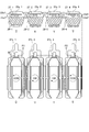
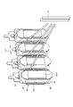
- FIG. 1 is a perspective view illustrating a configuration example of the stator 2 according to the first embodiment.
- FIG. 1 shows a stator 21 and an annular substrate (hereinafter referred to as a connection plate) 28 provided on the stator 21.
- the stator 21 is configured such that the upper insulator 24 and the lower insulator 25 are mounted on each piece of the connection core 23 in which a plurality (for example, four) pieces are connected via a bendable connection portion, and the coil 26 is wound around the pieces.
- the connecting portion is bent to form an annular shape by a plurality of (for example, three) connecting cores 23.
- the insulator includes an upper insulator 24 and a lower insulator 25.
- Each connecting core 23 forms a core as a whole stator as a segment.
- the number of segments is three.
- the number of segments is preferably three in order to increase the rigidity with respect to the second and fourth annular vibration modes, but may be an odd number of three or more.
- the number of pieces included in the plurality of connection cores 23 may be an even number, and the number of the plurality of connection cores 23 may be an odd number or a prime number. Even if the number of pieces is an even number, by setting the number of the connection cores 23 to an odd number or a prime number of 3 or more, it is possible to suppress the vibration of the motor and noise accompanying the vibration.
- connection plate 28 is for collectively wiring the terminals 27 provided on the upper insulator 24 for each piece (for each slot) of the connection core 23.
- a printed board or a flexible board is mounted on a printed board or a predetermined board. It is formed by the provided ones.
- the connection plate 28 may be connected to the terminal 27 after the connection core 23 around which the coil 26 is wound and the ring is temporarily assembled is inserted into the motor housing. Since the electrical connection of the coil 26 of each slot is made collectively by the connection plate 28 via the terminal 27, the crossover can be prevented from crossing. Further, a guide portion for guiding the crossover to the insulator is not required, so that the dimension of the stator in the rotation axis direction can be reduced, and the dead space of the motor can be reduced.
- the end 27-a of the terminal 27 is inserted into each of the plurality of holes 28a formed in the connection plate 28, and a part of the end 27-a of the terminal 27 is removed from the surface of the connection plate 28. It protrudes outward.
- the end 27-a of the terminal 27 is electrically connected to a part of the wiring formed on the connection plate. Protrusions 27-b and 27-c fixed to the insulator are connected to the end 27-a.
- FIG. 2 is a plan view showing an example of the shape of the steel plate 22 as a magnetic material constituting the connection core 23.
- a steel plate 22 is formed by punching out a magnetic steel plate with a mold or the like. Further, a plurality of steel plates 22 are stacked to form the connection core 23.
- FIG. 3A is a perspective view showing an example of the shape of the connection core 23, and FIG. 3B is a plan view showing an example of the shape of the connection core 23. 3B, enlarged views of both ends of the connection core 23 are added.
- the connection core 23 is formed by stacking a plurality of steel plates 22 as the magnetic material shown in FIG. Note that, in FIG. 3A, illustration of horizontal stripes on the end face, which is obtained by stacking electromagnetic steel sheets, is omitted.
- four pieces 23a having a substantially T-shaped planar shape are connected via a connecting portion 23b.
- Each piece 23a is formed with a tooth 23e.
- One end 23e1 (the end facing the rotor 3 in the radial direction) of the tooth 23e is a magnetic pole.
- the connecting portion 23b is formed to be thin between the planar edge 23ba located on the outer peripheral side and the curved concave portion 23bb located on the inner peripheral side, and the curved concave portion 23bb closes. It can be easily bent in any direction.
- the concave portion 23bb is provided on the side of the connecting portion 23b.
- a flat contact portion 23bc is connected to the curved concave portion 23bb and makes contact with the contact portion 23bc of the adjacent piece 23a when the connecting core 23 is bent.
- the left and right ends of the connection core 23 are formed as contact portions 23c and 23d, and come into contact with the contact portions 23d and 23c of the adjacent connection core 23 in a state where the connection core 23 is bent in an annular shape. .
- the surface of the contact portion 23c has a first surface 23c1 extending in a direction along the side surface 23e2 of the tooth 23e, and a second surface 23c2 inclined with respect to the first surface 23c1.
- the first surface 23c1 is disposed outside (on the side of the cylindrical portion 11) with respect to the second surface 23c2.
- the first surface 23c1 extends in a direction perpendicular to the direction in which the pieces 23a are arranged when the pieces 23a are opened and the connecting core 23 is linear.
- each of the first surface 23c1 and the second surface 23c2 extends radially from the contact portion 23c and passes through the center of the shaft (the center position of the motor).
- the contact portion 23d has a surface corresponding to the contact portion 23c of the other connecting core 23, and is inclined with respect to the second surface 23d2 extending in the direction along the side surface 23e3 of the tooth 23e and the second surface 23d2. And a first surface 23d1.
- the first surface 23d1 faces the first surface 23c1 of the contact portion 23c
- the second surface 23d2 faces the second surface 23c2.
- the first surface 23d1 is disposed outside (to the cylinder portion 11) with respect to the second surface 23d2.
- the second surface 23d2 extends in a direction perpendicular to the direction in which the pieces 23a are arranged when the pieces 23a are opened and the connecting core 23 is linear.
- the first surface 23d1 and the second surface 23d2 extend radially from the contact portion 23d and pass through the center of the shaft (the center position of the motor). Is a plane that intersects the plane along.
- the two connection cores 23 that are in contact with each other include the contact portions 23c and 23d, respectively, and extend in the radial direction to the contact portions 23c and 23d that the two connection cores 23 have.
- the contact portions 23c and 23d are not limited to the case where one is convex in the circumferential direction and the other is concave in the circumferential direction due to the surface of the structure described above. Good.
- the first surfaces 23c1 and 23d1 may extend in a direction perpendicular to the side surface 23e4 of the tooth.
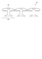
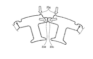
- FIGS. 4A and 4B are diagrams showing an example in which a plurality of connecting cores 23 are formed in a ring shape. It is to be noted that the formation of an annular core is conceptually shown. In practice, the upper insulator 24 and the lower insulator 25 are mounted on each piece of the connecting core 23 as described above, and the coil is wound and then bent. Is performed. In FIG. 4A, the three connecting cores 23 are each bent into an arc shape and then united to form an annular core as shown in FIG. 4B.
- FIG. 5 is a diagram illustrating an example of application of the upper insulator 24, the lower insulator 25, and the terminal 27 to the connection core 23.
- the upper insulator 24 and the lower insulator 25 have a vertically long (long in the direction in which the steel plates are stacked) coil bobbin so that the coil bobbin can be divided vertically in the vicinity of the center.
- the upper insulator 24 and the lower insulator 25 are mounted so as to accommodate the teeth 23e in a state where the teeth 23e are not held.
- a hole 24-a for a terminal 27 is provided in an upper portion of the upper insulator 24 (an end on the side of the lid 12 to be described later), into which the terminal 27 is inserted.
- the terminal 27 is provided with two protrusions 27-b and 27-c extending toward the upper insulator 24, and these two protrusions 27-b and 27-c are connected to the upper insulator 24.
- the terminal 27 is fixed to the upper insulator 24 while being inserted into the hole portion 24-a of the 24.
- the terminal 27 is provided with an end 27-a connected to the connection plate 28 and a hook 27n connected to a conductive wire.
- FIG. 6 is a diagram showing an example of winding the coil 26 in the connecting core 23.
- the upper part shows a plan view, and the lower part shows a front view.
- the point P1 is defined as the start of winding of the conductor W
- the conductor W is passed through the hook 27n-1 of the terminal 27-1 of the piece 23a-1, and then the conductor W is wound counterclockwise (CCW). It is turned to form the coil 26-1.
- the conductor W is wound clockwise (CW) around the piece 23a-2 from the end of the winding of the coil 26-1 to form the coil 26-2.
- the lead wire W is passed through the second hook 27n-2.
- the wire W is passed through the hook 27n-3 of the terminal 27-3 of the piece 23a-3, and then wound clockwise (CW) to form the coil 26-3.
- the wire W is wound counterclockwise (CCW) around the piece 23a-4 from the end of the winding of the coil 26-3 to form the coil 26-4, and the wire W is connected to the hook 27n- of the terminal 27-4. 4 and reaches the winding end point P2.
- the terminal is connected between the point P1 and the hook 27n-1 of the terminal 27-1.
- the wire W between the hook 27n-2 of the terminal 27-2 and the hook 27n-3 of the terminal 27-3 and the wire W between the hook 27n-4 of the terminal 27-4 and the point P2 are disconnected.
- winding start point P1 and the winding end point P2 may be reversed.
- clockwise (CW) and counterclockwise (CCW) windings may be reversed, but the first coil 26-1 and the second coil 26-2 are reversed, and the two The third coil 26-3 needs to be in the same direction as the third coil 26-2, and the third coil 26-3 and the fourth coil 26-4 need to be in opposite directions.
- the winding is performed like a single stroke.
- the connecting core 23 includes four pieces 23a-1 to 23a-4, the coils of the two pieces 23a-1 and 23a-4 located at both ends of the plurality of pieces in the circumferential direction.
- the direction of winding 26-1 and 26-4 is one direction, and the coil 26- of the two pieces 23a-2 and 23a-3 located between the two pieces 23a-1 and 23a-4 located at both ends.
- the winding direction of 2, 26-3 is opposite to the one direction.
- FIG. 6 is a diagram illustrating an example of phases assigned to each coil of the three segments.
- the first segment is assigned to the U inversion phase, the U phase, the V phase, and the V inversion phase, and the second segment is assigned.
- the third segment is assigned to the V inversion phase, the V phase, the W phase, and the W inversion phase.
- the surfaces 23c1 and 23d2 of the contact portions 23c and 23d of the two pieces on both sides of the connection core 23 are arranged in a direction perpendicular to the direction in which the plurality of pieces are arranged.
- a coil may be wound around each.
- the connecting core 23 is opened as shown in FIG. 6 and each piece 23a is opened and the coil 26 is wound in a state where the connecting core 23 is linear, the teeth are like a small motor. Can be easily wound even when the space around is small. Further, the winding of the coil 26 on the plurality of connecting cores 23 can be performed in parallel, which contributes to a significant improvement in productivity.
- FIG. 8 is a diagram showing another example of the winding of the coil 26.
- a conductor W is entangled with a first post (hereinafter referred to as a winding start post) 401 provided on a jig, and a coil 26-1 of the piece 23a-1 and a coil 26-1 of the piece 23a-2 are wound.
- a winding start post hereinafter referred to as a winding start post
- the coil 26-3 of the piece 23a-3 and the coil 26-4 of the piece 23a-4 are sequentially wound, and are wound on a second post (hereinafter referred to as a winding end post) 402 provided on the jig.
- a winding end post hereinafter referred to as a winding end post
- the hook 27n-1 of the terminal 27-1 starts winding and faces the post 401 side
- the hook 27n-2 of the terminal 27-2 faces the hook 27n-3 of the terminal 27-3
- the terminal 27- The fourth hook 27n-4 faces the post 402 side when the winding is completed.
- projections 24a-1 and 24a-2 are provided on the insulator on the upper surface of the portion where the pieces 23a-1 and 23a-2 face each other.
- the projections 24a-3 and 24a-4 are provided on the insulator on the upper surface of the portion where the pieces 23a-3 and 23a-4 face each other.
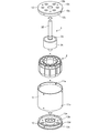
- FIG. 9A and 9B are perspective views showing a configuration example of the motor 1 to which the above-described stator 2 is applied.
- FIG. 9A shows an external appearance
- FIG. 9B shows main components.
- the motor 1 includes a tubular portion 11, lids 12, 13 and a shaft 32.
- the cylindrical part 11, the lid parts 12, 13 form a housing.
- a stator 2 is inserted (press-fitted) into a cylindrical tube portion 11, a rotor 3 is disposed in a space inside the stator 2, and a shaft of the rotor 3 is formed by upper and lower lid portions 12 and 13 holding bearings. 32 is rotatably supported.
- a plurality of holes 12 b are provided on a surface 12 a of the lid 12 facing the stator 2, and a plurality of holes 12 d are provided on an outer peripheral portion 12 c of the lid 12.
- a plurality of holes 13 b are provided on a surface 13 a of the lid 13 facing the stator 2
- a plurality of holes 13 d are provided on an outer peripheral portion 13 c of the lid 13.
- a member such as a screw is inserted and fixed to the holes 12d and 13d provided on the outer peripheral portions 12c and 13c of the lids 12 and 13 and the holes 11a and 11b provided on the outer peripheral portion of the cylindrical portion 11. good.
- a rotor 32 is provided on the shaft 32 as a magnetic material, and an annular magnet 3b is provided on the outer peripheral surface of the rotor yoke 3a.
- the rotor 3 includes an annular rotor yoke 3a formed by laminating electromagnetic steel sheets as magnetic members, and a shaft 32 provided through the rotor yoke 3a at the center of the rotor yoke 3a.
- the rotor yoke 3a is formed in a ring shape by bending four substantially fan-shaped pieces connected by a connecting portion so as to sandwich the rod-shaped shaft 32, and the connecting portion at the end of the connecting core extends in the axial direction. It is connected by laser welding or the like.
- the rotor yoke 3a is provided with a hole for generating reluctance torque, and a magnet is disposed in the hole as needed.
- the terminal 27 and the connection plate 28 of the stator 2 are not shown.
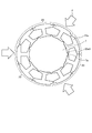
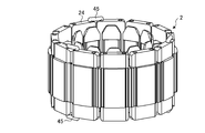
- FIGS. 10 and 11 are diagrams illustrating a configuration example of the connection core 23 according to the second embodiment, and illustrate an example of the connection core 23 applied to the outer rotor type motor 1.
- FIG. 10 six (6 segments) connecting cores 23 are annularly connected to form the stator 2.
- FIG. 11 shows one connecting core 23, which is provided with six pieces and bent in an arc shape. Although the thickness of the connecting portion between the pieces is uniform, a thin connecting portion as shown in FIG. 3A may be used.
- the connecting portion 23b which is a part of the steel plate, and the portion where the two contact portions 23bc are in contact ( The contact portion) forms a magnetic path.
- the connecting portion 23b has a large magnetic permeability, whereas the contact portion has a microscopic gap, so that the contact portion has the same magnetic permeability as air, and the difference in magnetic resistance of the contact portion with respect to the connecting portion 23b is large. .
- the magnetic flux concentrates on the connecting portion 23b to cause magnetic saturation, which may cause adverse effects such as generation of unnecessary heat.
- the use of grain-oriented electrical steel sheets in the manufacture of the connection core 23 reduces the difference in magnetic resistance between the connection portion 23b and the contact portion, makes it less likely to cause magnetic saturation, and generates unnecessary heat. I try to prevent the adverse effects.
- FIG. 12 is a view showing an example of a grain-oriented electrical steel sheet 9 according to the third embodiment.
- a grain-oriented electrical steel sheet is an electrical steel sheet whose magnetic properties are biased so that it is magnetized in a specific direction, such as by aligning the crystal axis direction when rolling the steel sheet.
- the difficulty is orthogonal to the difficulty.
- the vertical direction in the figure is the easy axis direction
- the horizontal direction in the figure is the hard magnetization direction.
- FIG. 13 is a diagram illustrating an example of the connection core 23 according to the third embodiment, and is an example of the connection core 23 formed by stacking steel sheets punched from the grain-oriented electrical steel sheet 9 in FIG. 12. It is. That is, the connection core 23 is formed of a grain-oriented electrical steel sheet, and the direction of the hard axis of magnetization of the grain-oriented electrical steel sheet is changed from one of the plurality of connection parts of the connection core 23 to the other connection part. It is the direction to go. Therefore, the direction in which the magnetic flux flows through the connecting portion 23b (the left-right direction in the figure) is the direction of the hard magnetization axis.
- the magnetic permeability in the direction of the easy axis and the direction of the hard axis have, for example, a difference of 100 times or more.
- the magnetic permeability in the easy axis direction is, for example, 10,000 to 100,000, but the hard axis direction is, for example, only about 100 to 1,000. Therefore, if the direction of the hard axis is set to the direction in which the magnetic flux flows in the connecting portion 23b, the magnetic permeability of the contact portion is 1 which is the same as the magnetic permeability of the air.
- the difference in magnetic resistance is smaller than when the easy axis is set in the direction in which the magnetic flux flows in the connecting portion 23b.
- the magnetic flux hardly flows not only to the connecting portion 23b but also to the contact portion, and it is possible to suppress the magnetic saturation at the connecting portion 23b, to reduce the magnetic loss and to suppress unnecessary heat generation.
- FIG. 9A and 9B the arrangement of the stator 2 in the motor 1 has been described. If the stator 2 in which the three connecting cores 23 are annularly arranged can be assembled by press-fitting into the housing, a highly accurate stator 2 can be manufactured in a short time. Therefore, the three connecting cores 23 can be easily assembled by press-fitting into the housing while maintaining the annularly arranged state. Therefore, in a fourth embodiment, a method of press-fitting the stator 2 using a jig will be described.
- FIGS. 14A to 14C are diagrams showing examples of press-fitting of the stator 2 according to the fourth embodiment.
- the cylindrical portion 11 of the housing is fitted to the lower jig 41.
- the lower jig 41 has a bottom portion 41a, an inner surface that is in close contact with the outer peripheral surface of the cylindrical portion 11, and a convex portion 41c that fits into a central hollow portion 41b (corresponding to the space of the rotor 3) of the stator 2. ing.
- the stator 2 including, for example, three connecting cores 23 in which the coil is wound and bent in an arc shape is inserted into the stator holding jig 42.
- the stator holding jig 42 has a contact portion 43 of a predetermined width protruding toward the center by a predetermined distance at a position corresponding to the contact portion of the three connection cores 23.
- an end portion (hereinafter, referred to as a guide piece) 43 a extends downward from the contact portion 43, and The guide piece 43a of the contact portion 43 is inserted into the inner periphery.
- FIG. 14C shows a state in which three connecting cores 23 are inserted into the stator holding jig 42, and the contact portions 23 d and 23 c of the connecting core 23 are moved toward the center by the contact portions 43 of the stator holding jig 42. Pressed to maintain the annulus.
- the two mating surfaces of the contact portions 23c and 23d of the adjacent connection core 23 extend in the radial direction from the contact portions 23c and 23d, as shown in an enlarged manner, and are in contact with the center of the rotor yoke 3a and the magnet 3b. And a plane intersecting a plane passing through the center of the shaft 32. Therefore, it is possible to prevent the contact portions 23c from meshing with each other and to be displaced in the radial direction, thereby increasing the roundness of the stator.
- the upper jig 44 is pressed from above the stator 2.
- the upper jig 44 includes an inner surface 44a that is in close contact with the outer peripheral surface of the stator 2, a convex portion 44b that fits into a hollow portion (equivalent to the space of the rotor 3) inside the stator 2, and a ceiling that is in contact with the upper surface of the stator 2. And a portion 44c.
- stator 2 When the contact portions 23c and 23d of the connection cores 23 of the stator 2 are held by the contact portions 43 of the holding jig 42 for the stator, the stator 2 is pushed downward by the upper jig 44, so that the stator 2 has a high height. It is press-fitted into the cylinder 11 while maintaining the circularity. Thus, a highly accurate stator 2 can be manufactured in a short time.
- FIG. 15 is a plan view showing an example of the shape of the connection core 23 according to the fifth embodiment.
- the magnetic pole back portions (portions on the outer peripheral side when the connecting core 23 is bent in an arc shape) of the individual pieces 23 a constituting the connecting core 23 are arranged in a direction perpendicular to the drawing sheet (the connecting core 23).
- a groove 23i is provided along the lamination direction of the steel plates).
- the steel plate is formed by stacking steel plates by providing notches corresponding to the grooves 23i in the steel plate.
- the groove 23i has a substantially rectangular opening shape on the inside, and is continuous with a narrow opening on the back side of the magnetic pole.
- connection core 23 is configured by three pieces 23a, it may be configured by four pieces or another number of pieces 23a as shown in FIG. 3A or the like. Also, contact portions 23c and 23d having the shapes shown in FIG. 3A and the like may be provided at both end portions of the connection core 23.
- connection core 23 having the configuration described with reference to FIG. 3A
- the annular stator 2 is configured from the plurality of connection cores 23.
- the connection portion 23b is easily subjected to stress due to vibration, and the connection portion 23b may be unintentionally deformed.
- a method for improving such a point will be presented.
- FIG. 16A and 16B are diagrams illustrating an example of insertion of the elastic member 291 according to the sixth embodiment.
- FIG. 16A illustrates a state before the connecting portion 23b of the connecting core 23 is bent
- FIG. 16B illustrates a connecting portion 23b. Has been bent.
- each connecting portion 23b of the connecting core 23 is provided with a curved concave portion 23bb.
- the concave portion 23bb is provided on the side where the space inside the connecting portion 23b is narrowed by bending the connecting portion 23b in the connecting portion 23b.
- An elastic member 291 such as a rod-shaped rubber is inserted into the curved concave portion 23bb.
- the size of the outer shape (hereinafter, referred to as a diameter) of the elastic member 291 is set to be larger than the size of a gap (hereinafter, referred to as an inner diameter) formed when the concave portion 23bb is bent. I have.
- the elastic member 291 generates a repulsive force in a direction from the inside to the outside with respect to the inner surface of the concave portion 23bb. Further, the timing of inserting the elastic member 291 is preferably after the coil is wound around the connecting core 23 in order to prevent the elastic member 291 from falling off. Note that the elastic members 291 may be inserted into all the recesses 23bb, or may be inserted at a rate of one per several recesses 23bb within a range where the symmetry of the stator 2 can be maintained.
- FIG. 16B shows a state after the connecting portion 23b of the connecting core 23 is bent and the connecting core 23 is formed in an arc shape.
- the diameter of the elastic member 291 is set to be larger than the inner diameter when the curved concave portion 23bb of the connecting portion 23b is bent, and a repulsive force acts from the inside by the compression of the elastic member 291. It is not completely bent.
- the three connection cores 23 are combined and press-fitted into the housing (cylinder portion 11) in a state of being temporarily assembled in an annular shape.
- the press-fitting may be performed without using a special jig, or may be performed using a jig as described with reference to FIGS. 14A and 14B.
- connection cores 23 (hereinafter, may be referred to as a temporary assembly stator) in an annularly temporarily assembled state are press-fitted into the housing, the temporary assembly is brought into contact with the inner surface of the housing to form a temporary assembly.
- An inward force acts on the stator, but the repulsive force of the elastic member 291 cancels out the force received from the inner surface of the housing.
- the outer peripheral surface of the temporary assembly stator in the canceling state approaches the roundness of the inner surface of the housing. Therefore, the temporary assembly stator is fixed with an adhesive or the like in the canceling state, so that good roundness can be maintained.
- the elastic core 291 since the elastic core 291 generates a force for pressing the connecting core 23 against the housing, the roundness according to the roundness of the inner surface of the housing is easily obtained.
- the vibration since the vibration is attenuated by the elastic member 291, unintended deformation of the connecting portion 23b is prevented, and the generation of noise is suppressed by the attenuation of the vibration.
- FIGS. 17A to 17C are diagrams showing examples of the projection 23g according to the seventh embodiment.
- FIG. 17A shows the band-shaped connecting core 23 before the plurality of connecting cores 23 are bent.
- Projections 23g are provided on pieces 23a as left and right ends of the strip-shaped connection core 23.
- a projection 23g is provided on a curved portion forming an outer peripheral portion of the piece 23a.
- the curved portion of the piece 23a is an arc portion 23f in the illustrated example, and a protrusion 23g is provided at one end of the arc portion 23f.
- the protruding portion 23g is located on the outermost side of the plurality of connection cores 23 when the plurality of connection cores 23 are bent in an annular shape, and forms the outermost peripheral portion of the plurality of connection cores 23 in an annular shape. ing. Therefore, at least the protrusion 23g and a part of the plurality of connection cores 23 are in contact with the inner surface of the cylindrical portion 11 of the housing.
- FIG. 17B shows a state in which three connecting cores 23 are press-fitted into the cylindrical portion 11, and the projection 23 g comes into contact with the inner surface of the cylindrical portion 11.
- the plurality of (for example, three) connection cores 23 are temporarily assembled and then press-fitted into the housing, the outer circumference of the connection core 23 or the outer circumference of the connection core 23 due to dimensional tolerance is expected. Only a few places receive the reaction force due to the press-fitting, and the temporarily assembled stator 2 separates the contact portions 23c and 23d at the ends of the connecting core 23 during the press-fitting, and the connecting core 23 is disjointed. Sometimes.
- the protrusion 23g when there is a protrusion 23g, as shown in FIG. 17C, the protrusion 23g receives a reaction force as indicated by an arrow from the housing side, thereby causing the contact portion 23c and the contact portion 23d to move in the circumferential direction. Since the pressing force acts, the connecting cores 23 are connected more firmly.
- the contact portions 23c and 23d at the ends of the connecting core 23 each have an irregular shape in the circumferential direction, and are fitted to each other to strengthen the pressing force in the circumferential direction. However, even if the contact portions 23c and 23d are flat end surfaces, a sufficient pressing force can be secured because the frictional force acts.
- the press-fitting may be performed without using a special jig, or may be performed using a jig as described with reference to FIGS. 14A and 14B. Further, the elastic member 291 shown in FIGS. 16A and 16B may be used together.
- FIG. 18 is a diagram illustrating an example of the protruding portion 23h according to the eighth embodiment, and illustrates the band-shaped connecting core 23 before being bent.
- an arc portion 23f as a curved portion is formed at an upper portion of a piece 23a which is a left and right end portion of the connecting core 23, and the arc portion 23f is a protruding portion 23h protruding toward a cylindrical portion of the housing. ing.
- the curvature of the protrusion 23h is changed to be small.
- the broken line indicates the arc portion 23f when the curvature is not changed.
- the advantages of the overhang 23h are the same as those of the protrusion 23g in FIGS. 17A to 17C.
- the plurality of connecting cores 23 may include a piece 23a having an arc portion and a piece 23a having a protrusion having a curvature different from the curvature of the arc portion.
- FIG. 19 is a diagram showing an example of a state in which the connecting core 23 according to the ninth embodiment is assembled in a ring shape.
- the illustrated connection core 23 is constituted by three pieces 23a as an example, it may be constituted by four pieces or another number of pieces 23a as shown in FIG. 3A or the like.
- the coil is assembled after the coil is wound, the coil is not shown for simplicity.
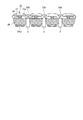
- FIG. 20 is a view showing a state where a plurality of connecting cores 23 are assembled in a ring shape.
- a plurality of connection cores 23 are combined on the outer periphery of the shaft 7 around a shaft 7 having a plurality of wedge-shaped projections 7a provided at equal intervals on the outer periphery.
- the wedge-shaped apex angle of the projection 7a of the shaft 7 is adjusted to the above-mentioned magnetic pole angle ⁇ , and the flat portion 23e5 of each piece 23a is arranged so as to contact the wedge-shaped slope of the projection 7a of the shaft 7. .
- each piece 23a is invited to the wedge-shaped protrusion 7a of the shaft rod 7 by applying a radial tightening force as shown by an arrow F to the outer peripheral surface of the connecting core 23 by a mold (not shown).
- the circularity of the annular core formed by the plurality of connecting cores 23 is increased.
- the three connecting cores 23 are integrally fixed by resin molding or the like.
- FIGS. 21A and 21B are diagrams illustrating an example of a temporary assembly of the stator 2 according to the tenth embodiment.
- FIG. 21A shows the upper insulator 24, and a hole (hereinafter, referred to as a connection metal fitting insertion hole) into which a connection metal 45 as a connection member is inserted on the left and right of the upper part of the upper insulator 24 in the rotation axis direction. 24b are provided.
- the holes for the terminals 27 are not shown.
- illustration of the lower insulator 25 is omitted, a connection fitting insertion hole into which the connection fitting 45 is inserted is provided below the lower insulator 25.
- connection fitting insertion hole 24b may be provided only for the piece 23a as the end of the connection core 23, but from the viewpoint of productivity, the upper insulator 24 and the lower insulator 25 are unified and have the same configuration. However, if it is permissible to prepare two types of the upper insulator 24 and the lower insulator 25, respectively, the upper insulator 24 and the lower insulator 24 provided with the connection fitting insertion holes 24b only for the end piece of the connection core 23.
- the insulator 25 may be used.
- connection fitting 45 is inserted across the upper insulator 24 and the lower insulator 25 of the two connection cores 23 whose ends are in contact with each other. Are linked.
- the connection fitting 45 is detached after the stator 2 is arranged in the housing by press fitting or the like.
- FIGS. 22A and 22B are diagrams illustrating an example of a temporary assembly of the stator 2 according to the eleventh embodiment.
- FIG. 22A shows the upper insulator 24, and a groove (hereinafter, referred to as an adhesive filling groove) 24 c having one end opened in the rotation axis direction is provided on the upper insulator 24. This groove extends in the circumferential direction. The illustration of the terminal holes is omitted.
- the lower insulator 25 is the same as that shown in FIG.
- thermosetting adhesive or a two-liquid adhesive is poured into an annular groove formed by the plurality of adhesive filling grooves 24c, and a plurality of couplings are formed.
- the core 23 is solidified while maintaining the annular shape.
- FIG. 23 is a perspective view showing an example of a terminal 27 according to the twelfth embodiment. Hooks 27b and 27c are provided in two vertical stages on one side of one end 27a of the terminal extending in the rotation axis direction.
- FIG. 24 is a perspective view showing an example of a general terminal 27 'according to the comparative example. Above one end 27d of the terminal extending in the rotation axis direction, hooks 27e are provided at both ends extending in the circumferential direction. 27f is provided.
- the hooks 27b and 27c are provided in two stages vertically and on the same one side, so that the winding is completed in a small space in the housing, and The space inside can be used effectively.
- a terminal of the type in which the end of the conductive wire is entangled with a hook may require an engaging portion (hereinafter, referred to as an azke pin) for hooking the conductive wire at the beginning and end of winding.
- an azure pin is provided on the outer frame jig outside the core (including the connection core 23) for winding, or in a special case, an azure pin is provided on a part of the insulator covering the core. In some cases. However, in the case where an azure pin is provided outside the core, handling of the outer frame jig is required up to a process such as welding for connection, and a dedicated winding outer frame jig is required for each core. In addition, when an azke pin is applied to an insulator, there is often little space around the azke pin, and the winding itself can be restricted, making the winding difficult. This embodiment presents a solution.
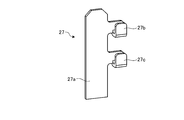
- FIG. 25 is a perspective view showing an example of the terminal 27 according to the thirteenth embodiment.
- the terminal 27h extends in the vertical direction (the direction from the insulator to the lid) and has an Azuke pin 27h at the center of the upper part of one end 27g of the terminal. And hooks 27i and 27j are provided on both upper wings.
- the azke pin 27h is present at the terminal 27, the winding of the winding is completed in a small space on the terminal 27. That is, at the time of winding, the winding jig is not necessary because the terminal 27 has the start and end of the winding pin 27h. Further, since there is no need to provide an azure pin on the insulator, the space occupied by the insulator in the housing is more utilized.
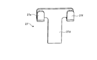
- FIG. 26 is a perspective view showing an example of the terminal 27 according to the fourteenth embodiment, in which an azke pin 27l is provided on one side of an end 27k extending in a vertical direction (a direction from an insulator to a lid), and Is provided with a hook 27m.
- the presence of the azke pin 27l at the terminal 27 completes the winding and entanglement of the winding in a small space on the terminal 27. That is, the winding jig is not required because the terminal 27 has the start and end winding azke pins 27l at the time of winding. Further, since there is no need to provide an azure pin on the insulator, the space occupied by the insulator in the housing is more utilized.
- connection core 23 having the configuration described with reference to FIG. 3A, the coils of each piece need to be connected to a desired circuit after the coils are wound around each piece and temporarily assembled in an annular shape.
- the connection requires a large-scale method such as a printed circuit board or a bus bar. This embodiment presents a solution.
- FIG. 27 is a perspective view showing an example of the upper insulator 24 according to the fifteenth embodiment.
- hooks 24d and 24e for assisting the crossover on the teeth side of the stator are provided on the upper portion of the upper insulator 24 so as to extend in the vertical direction (the direction from the insulator toward the lid).
- a plurality of grooves 24f and 24g for routing the crossover are provided on both sides of the upper part of the upper insulator 24.
- connection after winding of the coil of each piece for example, a crossover from a circumferentially opposed piece of the same phase is passed through the groove 24f on the outer peripheral portion to the hook 24d or the hook 24e ( And is connected to a terminal 27 (not shown) arranged above the upper insulator 24.
- the connecting wires can be more smoothly accommodated without requiring components such as a printed circuit board and a bus bar, and the superiority of the connecting core can be fully exhibited.
- connection core 23 having the configuration described with reference to FIG. 3A can be wound with the piece 23a opened, the coil may be required to be wound as much as possible. It is also an advantage of the connecting core 23 that it is possible, but when the plurality of connecting cores 23 are bent and assembled into an annular shape after the coil is wound, the coils wound to the limit may push each other. It is feared that the coil coating is broken and short-circuited. This embodiment presents a solution.
- FIGS. 28A and 28B are diagrams illustrating an example of insertion of a plate (hereinafter, referred to as a partition plate) 292 according to the sixteenth embodiment.
- FIG. 28A shows a partition plate 292 formed of an elastic member such as rubber, in which a bar portion 292a extending in the vertical direction and a rectangular flat plate portion 292b are integrally formed.
- the rod-shaped portion 292a of the partition plate 292 is inserted into the curved concave portion (23b-b) of the connecting portion 23b of the connecting core 23 around which the coil 26 is wound. Is provided with a flat plate portion 292b.
- FIG. 28B shows a state where the partition plate 292 is arranged in the stator 2.
- FIG. 29 is a diagram showing an example of a measure against a temperature rise according to the seventeenth embodiment.
- the upper insulator 24, the lower insulator 25, and the terminal 27 are attached to the respective pieces 23a of the linear connecting core 23 before bending, and the winding of the coil 26 is performed.
- the sheet-shaped (plate-shaped) resin member is a member (sheet) 8 formed of a gel having high thermal conductivity.
- the gel is, for example, a viscous one, a colloidal one, or a low fluidity, and is formed of a resin material such as silicone.
- FIG. 30 is a top view showing a state in which the sheet-like resin member 8 is inserted between the adjacent coils 26.
- FIG. 31 is a diagram illustrating a state in which the connection core 23 is bent in a state where the sheet-shaped resin member 8 is inserted.
- the connection core 23 is bent in an arc shape
- the connection core 23 is sandwiched between the coils 26.
- the sheet-shaped resin member 8 is crushed, and the coil 26 and the sheet-shaped resin member 8 come into close contact with each other. By doing so, the air region between the coils 26 having a low thermal conductivity is filled with the sheet-shaped resin member 8, so that the heat dissipation can be improved.
- a sheet-shaped resin member 8 is also provided between the coil 26 at the end of the other adjacent connection core 23 that is combined in an annular shape, and the sheet-shaped resin member 8 is pressed when being formed in an annular shape. You may make it be crushed.
- a plurality of coils 26 may be connected in parallel by the connection plate 28 shown in FIG. Since the parallel connection can be easily performed by using the connection plate 28, it is possible to realize an equivalently thick electric wire by the parallel connection of the windings without using a thick winding in order to enable operation at a large current. By using a thick winding, it is possible to suppress a decrease in space factor of the winding, an increase in winding resistance, an increase in thermal resistance, and an increase in coil end size.
- the motor according to the embodiment includes a stator, the stator includes a plurality of connection cores, and the connection core includes a plurality of pieces connected via a connection portion.
- the plurality of pieces are arranged in an arc shape, and the plurality of connecting cores are arranged in an annular shape.
- the stator includes three connecting cores, and the connecting core includes four pieces. Thereby, a more specific configuration can be provided.
- a coil wound around the piece is provided with a connection plate electrically connected. This facilitates connection and eliminates the need for a guide for guiding the crossover, thereby reducing the dead space of the motor.
- a thick electric wire can be equivalently realized by the parallel connection of the windings, and it is possible to cope with operation at a large current.
- the winding direction of the coil wound around two of the plurality of pieces is the same.
- the coils can be wound around the plurality of connected cores in parallel, which contributes to a significant improvement in productivity.
- the connecting core includes four pieces, and in the circumferential direction, among the plurality of pieces, the winding direction of the coil wound on the two pieces located at both ends is one direction, and between the two ends.
- the direction of winding of the coil wound on the two pieces located at the opposite direction is the one direction.
- the connecting core is formed of a grain-oriented electrical steel sheet, and the direction of the hard axis of magnetization of the grain-oriented electrical steel sheet is a direction from one of the connecting parts of the connecting core toward the other connecting part. It is. As a result, magnetic saturation of the connecting portion is prevented, and unnecessary heat generation due to magnetic loss is suppressed.
- connection cores that come into contact with each other have contact portions, and the contact portions of the two connection cores extend in the radial direction and intersect with a surface passing through the center of the shaft. Surface is provided. Thereby, the contact portions can be prevented from meshing with each other and being displaced in the radial direction, and the roundness of the stator can be increased.
- the number of pieces of the plurality of connecting cores is an even number, and the number of the plurality of connecting cores is an odd number or a prime number. Thereby, mounting can be facilitated.
- connection cores including the plurality of pieces connected via the connection portions are arranged in an arc shape, and the plurality of connection cores including the connection cores are arranged in an annular shape.
- the ends of the plurality of annularly arranged connecting cores are held by the contact portions of the jig, and the held plurality of connecting cores are pressed into the housing. More specifically, a plurality of connecting cores are press-fitted into the cylinder while the tip of the contact portion is inserted into the cylinder of the housing. Thereby, a highly accurate stator can be manufactured in a short time.
- the surfaces of the contact portions of the two pieces on both sides of the connecting core are arranged in a direction perpendicular to the direction in which the plurality of pieces are arranged, and the coil is wound around the connecting core.
- the coil can be wound around each piece of the connection core by the predetermined tension by the winding machine, and the occupancy of the coil can be increased.
- the motor includes a stator, the stator includes a plurality of connecting cores, the connecting core includes a plurality of pieces connected via the connecting portion, and a side portion of the connecting portion includes a concave portion.
- the plurality of connecting cores are arranged in a ring shape, and the elastic member is arranged in the recess.
- the vibration and noise of the stator can be reduced, and the productivity can be improved. That is, a force for expanding the piece is applied by the elastic member, and the plurality of connecting cores are pressed against the inner peripheral surface of the housing.
- the stator has a roundness equal to the roundness of the inner circumference of the housing.
- the elastic members are arranged in the recesses of the plurality of connecting cores. Thereby, the elastic members can be arranged uniformly, and the roundness can be realized.
- the elastic member is arranged in a part of the concave portions of the plurality of connecting cores. As a result, roundness can be realized with the necessary minimum number of elastic members.
- a housing is provided, and the outer peripheral portions of the plurality of pieces are in contact with the inner surface of the housing.
- a stator having a roundness equivalent to the roundness of the inner periphery of the housing is realized.
- the protrusions are provided on the outer peripheral portions of the two pieces at both ends of the connection core.
- an elastic member is arranged inside the concave portion of the connecting portion, and a plurality of connecting cores having a plurality of pieces connected by the connecting portion are arranged in an arc shape.
- the stator includes a stator, the stator includes a plurality of connection cores, the connection core includes a plurality of pieces connected via a connection portion, and among the plurality of pieces, two pieces at both ends of the connection core.
- a protrusion is provided on the outer peripheral portion.
- the plurality of connecting cores are arranged in a ring.
- Each of the protrusion 23g and the protrusion 23h is an example of a protrusion.
- the protruding portion is a protruding portion protruding from the outer peripheral portion of the piece. Thereby, the protruding portion can be easily formed.
- a housing is provided, and the protrusion contacts the inner surface of the housing. Thereby, strong contact between the connecting cores is realized.
- the side portion of the connecting portion has a concave portion, and an elastic member is arranged inside the concave portion. Therefore, the roundness of the stator is improved.
- connection core including a plurality of pieces connected via a connection portion
- a connection core including a plurality of pieces connected via connection portions at both ends of the connection core
- the protrusions are provided on the outer peripheral portions of the two pieces at both ends of the connection core, and a plurality of connection cores including the connection core are arranged in an annular shape.
- the present invention is not limited by the above embodiments.
- the present invention also includes a configuration in which the above-described components are appropriately combined. Further, further effects and modified examples can be easily derived by those skilled in the art. Therefore, the broader aspects of the present invention are not limited to the above-described embodiments, and various modifications are possible.
Landscapes
- Engineering & Computer Science (AREA)
- Power Engineering (AREA)
- Manufacturing & Machinery (AREA)
- Iron Core Of Rotating Electric Machines (AREA)
- Manufacture Of Motors, Generators (AREA)
Priority Applications (5)
| Application Number | Priority Date | Filing Date | Title |
|---|---|---|---|
| CN201980056301.7A CN112640259B (zh) | 2018-08-24 | 2019-05-31 | 马达 |
| JP2020538183A JP7326293B2 (ja) | 2018-08-24 | 2019-05-31 | モータ |
| CN202411848280.1A CN119853323A (zh) | 2018-08-24 | 2019-05-31 | 呈环状临时组装的定子 |
| US17/269,694 US11996735B2 (en) | 2018-08-24 | 2019-05-31 | Motor |
| JP2023126331A JP7727690B2 (ja) | 2018-08-24 | 2023-08-02 | 環状に仮組みされたステータ |
Applications Claiming Priority (6)
| Application Number | Priority Date | Filing Date | Title |
|---|---|---|---|
| JP2018157661 | 2018-08-24 | ||
| JP2018-157660 | 2018-08-24 | ||
| JP2018157659 | 2018-08-24 | ||
| JP2018157660 | 2018-08-24 | ||
| JP2018-157659 | 2018-08-24 | ||
| JP2018-157661 | 2018-08-24 |
Publications (1)
| Publication Number | Publication Date |
|---|---|
| WO2020039682A1 true WO2020039682A1 (ja) | 2020-02-27 |
Family
ID=69592592
Family Applications (1)
| Application Number | Title | Priority Date | Filing Date |
|---|---|---|---|
| PCT/JP2019/021748 Ceased WO2020039682A1 (ja) | 2018-08-24 | 2019-05-31 | モータおよびモータの製造方法 |
Country Status (4)
| Country | Link |
|---|---|
| US (1) | US11996735B2 (https=) |
| JP (2) | JP7326293B2 (https=) |
| CN (2) | CN112640259B (https=) |
| WO (1) | WO2020039682A1 (https=) |
Cited By (4)
| Publication number | Priority date | Publication date | Assignee | Title |
|---|---|---|---|---|
| WO2022107875A1 (ja) * | 2020-11-20 | 2022-05-27 | ミネベアミツミ株式会社 | モータ |
| WO2022107874A1 (ja) * | 2020-11-20 | 2022-05-27 | ミネベアミツミ株式会社 | モータ |
| EP4035833A1 (en) * | 2021-02-02 | 2022-08-03 | Black & Decker, Inc. | Canned brushless motor |
| EP4277087A4 (en) * | 2021-01-06 | 2024-12-11 | LG Magna e-Powertrain Co., Ltd. | Motor |
Families Citing this family (8)
| Publication number | Priority date | Publication date | Assignee | Title |
|---|---|---|---|---|
| JP7807914B2 (ja) * | 2021-12-27 | 2026-01-28 | 愛知電機株式会社 | 電動機及び圧縮機 |
| JP2023097280A (ja) * | 2021-12-27 | 2023-07-07 | 愛知電機株式会社 | 電動機及び圧縮機 |
| JP7824074B2 (ja) * | 2021-12-27 | 2026-03-04 | 愛知電機株式会社 | 電動機及び圧縮機 |
| DE102022200859A1 (de) | 2022-01-26 | 2023-07-27 | Brose Fahrzeugteile SE & Co. Kommanditgesellschaft, Würzburg | Stator für einen Elektromotor |
| GB2626581A (en) * | 2023-01-27 | 2024-07-31 | Dyson Technology Ltd | A stator assembly |
| WO2024214620A1 (ja) | 2023-04-10 | 2024-10-17 | ソフトバンクグループ株式会社 | ロボット、ロボットの制御プログラム、情報処理装置、学習データの生成方法、動作パラメータの生成方法、プログラム、学習済モデルの生成方法 |
| CN116418183A (zh) * | 2023-04-10 | 2023-07-11 | 瑞声开泰声学科技(上海)有限公司 | 定子铁芯制作方法和外转子电机 |
| FR3160074A1 (fr) * | 2024-03-11 | 2025-09-12 | Bontaz Centre | Stator circulaire pour bicyclette a assistance electrique |
Citations (6)
| Publication number | Priority date | Publication date | Assignee | Title |
|---|---|---|---|---|
| JPH0847185A (ja) * | 1994-08-03 | 1996-02-16 | Matsushita Electric Ind Co Ltd | モータの鉄心 |
| JP2005245138A (ja) * | 2004-02-27 | 2005-09-08 | Japan Servo Co Ltd | モータ |
| JP2007282498A (ja) * | 2007-05-31 | 2007-10-25 | Mitsui High Tec Inc | 積層鉄心及びその製造方法 |
| JP2010178426A (ja) * | 2009-01-27 | 2010-08-12 | Daihatsu Motor Co Ltd | ステータコア |
| JP2013094059A (ja) * | 2013-02-19 | 2013-05-16 | Mitsubishi Electric Corp | 回転電機 |
| JP2014183631A (ja) * | 2013-03-18 | 2014-09-29 | Honda Motor Co Ltd | 圧入固定構造 |
Family Cites Families (26)
| Publication number | Priority date | Publication date | Assignee | Title |
|---|---|---|---|---|
| JP3568364B2 (ja) * | 1996-09-30 | 2004-09-22 | 松下電器産業株式会社 | 回転電機のコア |
| TW483216B (en) | 1998-09-08 | 2002-04-11 | Toshiba Corp | Motor |
| JP4405000B2 (ja) | 1998-09-08 | 2010-01-27 | 株式会社東芝 | モータ |
| JP2000139052A (ja) * | 1998-11-02 | 2000-05-16 | Matsushita Electric Ind Co Ltd | 電動機のステータ |
| JP2000209796A (ja) * | 1999-01-13 | 2000-07-28 | Matsushita Electric Ind Co Ltd | 電動機およびそのステ―タコアの製造方法 |
| JP2007074875A (ja) * | 2005-09-09 | 2007-03-22 | Toyota Motor Corp | ステータコア、モータ、ステータ製造方法 |
| JPWO2007043224A1 (ja) * | 2005-10-12 | 2009-04-16 | パナソニック株式会社 | 固定子及びこれを適用したモータ、及びこの固定子の製造方法 |
| JP4711877B2 (ja) | 2006-04-13 | 2011-06-29 | 株式会社山田製作所 | 焼結コア連結構造の製造法及びその焼結コア連結構造 |
| CN100514804C (zh) * | 2006-07-11 | 2009-07-15 | 天津大学 | 分段式模块化定子结构直驱型永磁同步风力发电机 |
| CN101030712A (zh) | 2007-01-09 | 2007-09-05 | 天津大学 | 分段式模块化定子结构直驱型低速直流无刷电动机 |
| CN201298796Y (zh) | 2008-08-18 | 2009-08-26 | 于波 | 直驱式混励型风能发电机 |
| CN101442224A (zh) | 2008-12-30 | 2009-05-27 | 卧龙电气集团股份有限公司 | 分块式铁芯结构及成圆方法 |
| JP5389559B2 (ja) * | 2009-07-23 | 2014-01-15 | 愛三工業株式会社 | 回転電動機の固定子及び燃料ポンプ |
| JP5938156B2 (ja) | 2011-07-08 | 2016-06-22 | 日本電産テクノモータ株式会社 | 固定子コア、並びに、該固定子コアを備えたモータ及びその製造方法 |
| CN202455169U (zh) | 2011-12-31 | 2012-09-26 | 宁波杭州湾新区北斗电机有限公司 | 一种电机铁芯冲片 |
| CN103812236B (zh) | 2012-11-12 | 2016-12-21 | 珠海格力节能环保制冷技术研究中心有限公司 | 定子及其制造方法和具有该定子的电动机、压缩机 |
| JP2015171239A (ja) * | 2014-03-07 | 2015-09-28 | アイシン精機株式会社 | 回転電機のステータ及び回転電機 |
| KR101679470B1 (ko) * | 2014-05-16 | 2016-11-25 | 뉴모텍(주) | 모터의 적층 코어 및 제조 방법 |
| JP6649733B2 (ja) | 2015-09-30 | 2020-02-19 | 日本電産サンキョー株式会社 | ステータ、モータおよびポンプ装置 |
| CN105490410B (zh) | 2015-12-31 | 2019-05-31 | 广东美的环境电器制造有限公司 | 定子组件、定子组件的制备方法及具有该定子组件的电机 |
| KR102604381B1 (ko) * | 2016-07-07 | 2023-11-21 | 엘지이노텍 주식회사 | 스테이터 유닛, 스테이터 및 이를 포함하는 모터 |
| JP2018068069A (ja) | 2016-10-21 | 2018-04-26 | 日本電産テクノモータ株式会社 | ステータ、モータ、およびステータの製造方法 |
| JP2018074638A (ja) | 2016-10-24 | 2018-05-10 | 日本電産テクノモータ株式会社 | ステータ、モータ、およびステータの製造方法 |
| WO2018230384A1 (ja) * | 2017-06-14 | 2018-12-20 | 株式会社 マキタ | 電動工具 |
| CN107332366A (zh) | 2017-06-29 | 2017-11-07 | 合普动力股份有限公司 | 分瓣式定子铁芯的紧固结构 |
| CN117280572A (zh) * | 2021-05-24 | 2023-12-22 | 三菱电机株式会社 | 绝缘体、定子、旋转电机、定子的制造方法以及旋转电机的制造方法 |
-
2019
- 2019-05-31 CN CN201980056301.7A patent/CN112640259B/zh active Active
- 2019-05-31 WO PCT/JP2019/021748 patent/WO2020039682A1/ja not_active Ceased
- 2019-05-31 US US17/269,694 patent/US11996735B2/en active Active
- 2019-05-31 JP JP2020538183A patent/JP7326293B2/ja active Active
- 2019-05-31 CN CN202411848280.1A patent/CN119853323A/zh active Pending
-
2023
- 2023-08-02 JP JP2023126331A patent/JP7727690B2/ja active Active
Patent Citations (6)
| Publication number | Priority date | Publication date | Assignee | Title |
|---|---|---|---|---|
| JPH0847185A (ja) * | 1994-08-03 | 1996-02-16 | Matsushita Electric Ind Co Ltd | モータの鉄心 |
| JP2005245138A (ja) * | 2004-02-27 | 2005-09-08 | Japan Servo Co Ltd | モータ |
| JP2007282498A (ja) * | 2007-05-31 | 2007-10-25 | Mitsui High Tec Inc | 積層鉄心及びその製造方法 |
| JP2010178426A (ja) * | 2009-01-27 | 2010-08-12 | Daihatsu Motor Co Ltd | ステータコア |
| JP2013094059A (ja) * | 2013-02-19 | 2013-05-16 | Mitsubishi Electric Corp | 回転電機 |
| JP2014183631A (ja) * | 2013-03-18 | 2014-09-29 | Honda Motor Co Ltd | 圧入固定構造 |
Cited By (17)
| Publication number | Priority date | Publication date | Assignee | Title |
|---|---|---|---|---|
| WO2022107874A1 (ja) * | 2020-11-20 | 2022-05-27 | ミネベアミツミ株式会社 | モータ |
| JP2022082267A (ja) * | 2020-11-20 | 2022-06-01 | ミネベアミツミ株式会社 | モータ |
| JP2022082266A (ja) * | 2020-11-20 | 2022-06-01 | ミネベアミツミ株式会社 | モータ |
| WO2022107875A1 (ja) * | 2020-11-20 | 2022-05-27 | ミネベアミツミ株式会社 | モータ |
| CN116325431A (zh) * | 2020-11-20 | 2023-06-23 | 美蓓亚三美株式会社 | 电机 |
| US12567773B2 (en) | 2020-11-20 | 2026-03-03 | Minebea Mitsumi Inc. | Motor with stator segments coupled via protruding parts and recesses with different planes |
| JP7705237B2 (ja) | 2020-11-20 | 2025-07-09 | ミネベアミツミ株式会社 | モータ |
| JP7637495B2 (ja) | 2020-11-20 | 2025-02-28 | ミネベアミツミ株式会社 | モータ |
| EP4277087A4 (en) * | 2021-01-06 | 2024-12-11 | LG Magna e-Powertrain Co., Ltd. | Motor |
| US12587047B2 (en) | 2021-01-06 | 2026-03-24 | Lg Magna E-Powertrain Co., Ltd. | Segmented stator core for an electric motor |
| EP4035833A1 (en) * | 2021-02-02 | 2022-08-03 | Black & Decker, Inc. | Canned brushless motor |
| US11955863B2 (en) | 2021-02-02 | 2024-04-09 | Black & Decker Inc. | Circuit board assembly for compact brushless motor |
| US11876424B2 (en) | 2021-02-02 | 2024-01-16 | Black & Decker Inc. | Compact brushless motor including in-line terminals |
| US12261497B2 (en) | 2021-02-02 | 2025-03-25 | Black & Decker Inc. | High-power motor for a body-grip power tool |
| US11870316B2 (en) | 2021-02-02 | 2024-01-09 | Black & Decker, Inc. | Brushless motor including a nested bearing bridge |
| US11855521B2 (en) | 2021-02-02 | 2023-12-26 | Black & Decker, Inc. | Brushless DC motor for a body-grip power tool |
| US11837935B2 (en) | 2021-02-02 | 2023-12-05 | Black & Decker, Inc. | Canned brushless motor |
Also Published As
| Publication number | Publication date |
|---|---|
| CN112640259A (zh) | 2021-04-09 |
| CN119853323A (zh) | 2025-04-18 |
| US20210320539A1 (en) | 2021-10-14 |
| JPWO2020039682A1 (ja) | 2021-08-10 |
| US11996735B2 (en) | 2024-05-28 |
| JP7727690B2 (ja) | 2025-08-21 |
| JP2023133515A (ja) | 2023-09-22 |
| JP7326293B2 (ja) | 2023-08-15 |
| CN112640259B (zh) | 2025-01-10 |
Similar Documents
| Publication | Publication Date | Title |
|---|---|---|
| JP7727690B2 (ja) | 環状に仮組みされたステータ | |
| JP6328319B2 (ja) | 電機子および回転電機 | |
| CN103597714B (zh) | 旋转电机用转子、旋转电机以及旋转电机用转子的制造方法 | |
| US10069387B2 (en) | Fixing method and fixing structure for fixing a coil insulator, stator using the same and rotating electrical machine using the same | |
| CN107078565A (zh) | 用于旋转电机的定子 | |
| JP2012228104A (ja) | 永久磁石埋込型電動機 | |
| JP2013046420A (ja) | 巻線、および巻線を備えたステータコア | |
| US20180076679A1 (en) | Stator for rotary electric machine | |
| JP5977311B2 (ja) | コイル固定部品を備えた固定子及び該固定子を備えた電動機 | |
| CN113544945B (zh) | 定子 | |
| JPWO2017141562A1 (ja) | 回転電機の固定子、回転電機、および、回転電機の固定子の製造方法 | |
| JP2008187841A (ja) | 電機子コア、電機子、及びモータ、並びに電機子コアの製造方法 | |
| CN115516739B (zh) | 马达 | |
| JP2010183660A (ja) | ステータ、ブラシレスモータ、ステータの製造方法、及び、ブラシレスモータの製造方法 | |
| JP2017225208A (ja) | 電機子、回転電機および電機子の製造方法 | |
| JP2012205489A (ja) | 回転電機の固定子及びその製造方法 | |
| JP6429400B2 (ja) | ステータコア、ステータ及び回転電機 | |
| JP2014042402A (ja) | 回転電機 | |
| JPWO2019146499A1 (ja) | 回転電機の固定子及び回転電機の固定子の製造方法 | |
| EP4300773A1 (en) | Stator and brushless motor | |
| JP6095462B2 (ja) | 回転電機の電機子、回転電機、および回転電機の電機子の製造方法 | |
| JP7229402B2 (ja) | 電機子の製造方法、及び、電機子 | |
| JP2014135786A (ja) | 回転電機用ステータおよび回転電機 | |
| EP4250534A1 (en) | Motor | |
| EP4250533A1 (en) | Motor |
Legal Events
| Date | Code | Title | Description |
|---|---|---|---|
| 121 | Ep: the epo has been informed by wipo that ep was designated in this application |
Ref document number: 19852191 Country of ref document: EP Kind code of ref document: A1 |
|
| WWE | Wipo information: entry into national phase |
Ref document number: 2020538183 Country of ref document: JP |
|
| NENP | Non-entry into the national phase |
Ref country code: DE |
|
| 122 | Ep: pct application non-entry in european phase |
Ref document number: 19852191 Country of ref document: EP Kind code of ref document: A1 |
|
| WWG | Wipo information: grant in national office |
Ref document number: 201980056301.7 Country of ref document: CN |