WO2020003940A1 - レンズ鏡胴 - Google Patents
レンズ鏡胴 Download PDFInfo
- Publication number
- WO2020003940A1 WO2020003940A1 PCT/JP2019/022367 JP2019022367W WO2020003940A1 WO 2020003940 A1 WO2020003940 A1 WO 2020003940A1 JP 2019022367 W JP2019022367 W JP 2019022367W WO 2020003940 A1 WO2020003940 A1 WO 2020003940A1
- Authority
- WO
- WIPO (PCT)
- Prior art keywords
- lens group
- lens
- axis
- sub
- main
- Prior art date
- Legal status (The legal status is an assumption and is not a legal conclusion. Google has not performed a legal analysis and makes no representation as to the accuracy of the status listed.)
- Ceased
Links
Images





Classifications
-
- G—PHYSICS
- G02—OPTICS
- G02B—OPTICAL ELEMENTS, SYSTEMS OR APPARATUS
- G02B7/00—Mountings, adjusting means, or light-tight connections, for optical elements
- G02B7/02—Mountings, adjusting means, or light-tight connections, for optical elements for lenses
- G02B7/04—Mountings, adjusting means, or light-tight connections, for optical elements for lenses with mechanism for focusing or varying magnification
- G02B7/10—Mountings, adjusting means, or light-tight connections, for optical elements for lenses with mechanism for focusing or varying magnification by relative axial movement of several lenses, e.g. of varifocal objective lens
-
- G—PHYSICS
- G02—OPTICS
- G02B—OPTICAL ELEMENTS, SYSTEMS OR APPARATUS
- G02B7/00—Mountings, adjusting means, or light-tight connections, for optical elements
- G02B7/02—Mountings, adjusting means, or light-tight connections, for optical elements for lenses
- G02B7/04—Mountings, adjusting means, or light-tight connections, for optical elements for lenses with mechanism for focusing or varying magnification
- G02B7/10—Mountings, adjusting means, or light-tight connections, for optical elements for lenses with mechanism for focusing or varying magnification by relative axial movement of several lenses, e.g. of varifocal objective lens
- G02B7/102—Mountings, adjusting means, or light-tight connections, for optical elements for lenses with mechanism for focusing or varying magnification by relative axial movement of several lenses, e.g. of varifocal objective lens controlled by a microcomputer
-
- G—PHYSICS
- G02—OPTICS
- G02B—OPTICAL ELEMENTS, SYSTEMS OR APPARATUS
- G02B15/00—Optical objectives with means for varying the magnification
- G02B15/14—Optical objectives with means for varying the magnification by axial movement of one or more lenses or groups of lenses relative to the image plane for continuously varying the equivalent focal length of the objective
- G02B15/145—Optical objectives with means for varying the magnification by axial movement of one or more lenses or groups of lenses relative to the image plane for continuously varying the equivalent focal length of the objective having five groups only
-
- G—PHYSICS
- G02—OPTICS
- G02B—OPTICAL ELEMENTS, SYSTEMS OR APPARATUS
- G02B15/00—Optical objectives with means for varying the magnification
- G02B15/14—Optical objectives with means for varying the magnification by axial movement of one or more lenses or groups of lenses relative to the image plane for continuously varying the equivalent focal length of the objective
- G02B15/145—Optical objectives with means for varying the magnification by axial movement of one or more lenses or groups of lenses relative to the image plane for continuously varying the equivalent focal length of the objective having five groups only
- G02B15/1451—Optical objectives with means for varying the magnification by axial movement of one or more lenses or groups of lenses relative to the image plane for continuously varying the equivalent focal length of the objective having five groups only the first group being positive
- G02B15/145123—Optical objectives with means for varying the magnification by axial movement of one or more lenses or groups of lenses relative to the image plane for continuously varying the equivalent focal length of the objective having five groups only the first group being positive arranged +++-+
-
- G—PHYSICS
- G02—OPTICS
- G02B—OPTICAL ELEMENTS, SYSTEMS OR APPARATUS
- G02B15/00—Optical objectives with means for varying the magnification
- G02B15/14—Optical objectives with means for varying the magnification by axial movement of one or more lenses or groups of lenses relative to the image plane for continuously varying the equivalent focal length of the objective
- G02B15/16—Optical objectives with means for varying the magnification by axial movement of one or more lenses or groups of lenses relative to the image plane for continuously varying the equivalent focal length of the objective with interdependent non-linearly related movements between one lens or lens group, and another lens or lens group
Definitions
- the present invention relates to a lens barrel, and more particularly, to a lens barrel capable of independently driving a plurality of lens groups.
- a lens barrel that includes a plurality of linear actuators in a lens barrel and can independently drive a plurality of lens groups is known.
- Patent Literature 1 discloses a lens barrel including two voice coil motors (Voice Coil Motors; VCM) in the lens barrel and independently driving two lens groups by each VCM.
- the lens barrel described in Patent Document 1 has a configuration in which two lens groups are movably supported along a common main axis and a common sub-axis.
- Patent Document 2 in a lens barrel configured to drive two lens groups independently by two VCMs, the two lens groups are movably supported along a common sub-axis, and A configuration is described in which the support is provided movably along a separately prepared main shaft.
- individual main axes are arranged on the same circumference centered on the optical axis. That is, they are arranged shifted in the circumferential direction.
- a lens barrel in which two lens groups move along a common principal axis as in Patent Literature 1 has the disadvantage that the movable range of each lens group is limited, and the sliding of each lens group.
- Increasing the length of the section has the disadvantage that the overall length of the lens barrel is increased.
- the VCM drives the lens group by the magnetic sensor. Is disposed at an asymmetric position with respect to the driving magnet. Since the magnetic sensor performs position detection using a magnetic field, if it is disposed at an asymmetric position with respect to the driving magnet of the VCM, there is a disadvantage that the detection accuracy is reduced.
- the present invention has been made in view of such circumstances, and provides a lens barrel that can stably support a movable lens group with a compact configuration and that can accurately detect the position of the movable lens group.
- the purpose is to:
- a first lens frame provided with a first main guide portion slidable along a first sub-axis and a second main guide portion slidable along a second main axis.
- a second lens frame having a second sub-guide portion that slides along the two sub-axes; a first driving portion that includes a plurality of first driving magnets and drives the first lens frame; A second driving unit that includes a driving magnet and drives the second lens frame; and a second driving unit that detects the position of the first position detecting magnet provided on the first lens frame and detects the position of the first lens frame.
- a first main axis and a first sub-axis are arranged on a straight line passing through the second main axis and the second sub-axis in a cross section orthogonal to the optical axis, and The first main shaft and the second main shaft are arranged to be at least partially overlapped with each other in the direction of the optical axis, and the first main shaft and the second main shaft are arranged on the inner diameter side of the second main shaft and the second sub shaft.
- the detector is disposed on a straight line passing through the second main axis and the second sub-axis in a cross section orthogonal to the optical axis, and the plurality of first driving magnets and the plurality of second driving magnets are orthogonal to the optical axis.
- a lens barrel which is symmetrically arranged in a cross section with respect to a straight line passing through a second main axis and a second sub axis.
- the first lens frame and the second lens frame are independently driven by the first drive unit and the second drive unit. Further, the first and second position detectors individually detect the position.
- the first lens frame is movably supported along the first main axis and the first sub-axis
- the second lens frame is movably supported along the second main axis and the second sub-axis.
- the first main axis and the first sub-axis for guiding the movement of the first lens frame are arranged parallel to each other with the optical axis interposed therebetween.
- the second main axis and the second sub-axis guided by the movement of the second lens frame are arranged in parallel with each other with the optical axis interposed therebetween.
- the first main axis and the first sub-axis for guiding the movement of the first lens frame and the second main axis and the second sub-axis for guiding the movement of the second lens frame are arranged in parallel with each other, and are aligned with the optical axis. It is arranged along. Further, these axes are arranged as follows. That is, the first main axis and the first sub-axis are arranged on a straight line passing through the second main axis and the second sub-axis in a cross section orthogonal to the optical axis, and are closer to the inner diameter than the second main axis and the second sub-axis.
- first main axis and the second main axis are arranged so as to overlap at least partially in the direction of the optical axis.
- the lengths of the first main shaft and the second main shaft can be secured. Thereby, the lengths of the first main guide portion and the second main guide portion can be secured, and the first lens frame and the second lens frame can be stably supported.
- a first position detecting unit for detecting the position of the first lens frame, a second position detecting unit for detecting the position of the second lens frame, a plurality of first driving magnets and a plurality of second driving magnets are provided.
- the first position detection unit and the second position detection unit are arranged on a straight line passing through the second main axis and the second sub-axis in a cross section orthogonal to the optical axis.
- the plurality of first driving magnets and the plurality of second driving magnets are arranged symmetrically with respect to a straight line passing through the second main axis and the second sub-axis in a cross section orthogonal to the optical axis.
- the first position detecting section and the second position detecting section can be arranged symmetrically with respect to the first driving magnet and the second driving magnet, and the positions of the first lens frame and the second lens frame can be accurately detected. it can.
- the distinction between the main axis and the sub axis is as follows. That is, the axis on the side that more stably supports the lens frame is the main axis. Therefore, the distinction between the main shaft and the sub shaft is determined by the relationship with the main guide portion and the sub guide portion.
- the guide section on the side that guides the lens frame more stably is the main guide section, and the axis on which the main guide section slides is the main axis.
- the first position detection magnet of the first position detection unit disposed relatively inside the second position detection unit is provided on the side of the first sub-guide unit.
- a second position detecting magnet of the second position detecting unit which is disposed relatively outside the first position detecting unit, is provided on the side of the second main guide unit.
- the main guide portion is structurally larger than the sub guide portion.
- the second position detection magnet of the second position detection unit disposed relatively outside the first position detection unit is provided in the second main guide unit. Since the main guide portion is the portion that moves most stably, the main guide portion is provided with the second position detecting magnet, so that the position of the second lens frame can be accurately detected.
- the lens frame (first lens frame) having the shorter movement stroke is guided by the main axis (first main axis) and the sub-axis (first sub-axis) arranged inside.
- the structure of the inner guide can be relatively reduced in size, and the whole can be made more compact.
- the first position detection unit that detects the position of the first lens frame is configured by a Hall element
- the second position detection unit that detects the position of the second lens frame is configured by a magnetoresistive element. . That is, the position of the lens frame (first lens frame) having the shorter moving stroke is detected by the Hall element, and the position of the lens frame (second lens frame) having the longer moving stroke is detected by the magnetoresistive element. Is composed of Since the first lens frame is guided by a main axis (first main axis) and a sub-axis (first sub-axis) arranged inside, the position of the first lens frame is detected by a Hall element, so that the overall structure is improved. It can be more compact.
- the lighter lens frame (first lens frame) is guided by the main axis (first main axis) and the sub-axis (first sub-axis) arranged inside.
- the structure of the inner guide can be relatively downsized while stably supporting each lens frame. This also makes it possible to make the whole more compact.
- the main axis (first main axis) that guides the lighter lens frame (first lens frame) is connected to the main axis (second main axis) of the heavier lens frame (second lens frame).
- first main axis that guides the lighter lens frame (first lens frame)
- second main axis of the heavier lens frame
- the first drive unit is constituted by a moving magnet type voice coil motor. Therefore, the first drive unit includes a drive magnet (first drive magnet) on the first lens frame. This makes it possible to relatively reduce the size of the inner drive section (first drive section), and further downsize the entire drive section.
- the second drive unit is configured by a moving coil type voice coil motor. Therefore, in the second drive unit, a drive coil is provided in the second lens frame. Thereby, the weight of the second lens frame can be reduced. In addition, this enables high-speed and stable driving.
- a first cylinder having a first main axis and a first sub-axis and holding a first lens frame; a second cylinder having a second main axis and a second sub-axis and holding a second lens frame;
- the lens barrel according to any one of (1) to (9), further including: a driving unit configured to move at least one of the first cylinder and the second cylinder along the optical axis.
- the first cylinder and the second cylinder that relatively move along the optical axis are provided.
- the first lens frame is held by the first cylinder and moves relatively to the first cylinder.
- the second lens frame is held by the second cylinder and moves relatively to the second cylinder.
- the power of the drive unit does not matter. Therefore, it may be manual.
- the drive unit includes a fixed cylinder having a first straight groove and a second straight groove, a first cam groove and a second cam groove, and a cam cylinder fitted to the fixed cylinder and a first cylinder.
- the drive unit is constituted by a so-called cam mechanism, and the first cylinder and the second cylinder move relatively by rotating the cam cylinder relative to the fixed cylinder.
- a movable lens group can be stably supported in a compact configuration, and the position of the movable lens group can be accurately detected.
- FIG. 1 Side sectional view showing one embodiment of an interchangeable lens to which the present invention is applied.
- a diagram showing a moving state of each lens group when a zoom operation is performed Sectional drawing which shows the support structure of a 3rd lens group movable holding frame and a 4th lens group movable holding frame.
- Sectional view showing the mounting structure of the front drive unit of the third lens group.
- Sectional drawing which shows the mounting structure of a 4th lens group drive part.
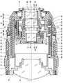
- FIG. 1 is a side sectional view showing an embodiment of an interchangeable lens to which the present invention is applied.
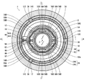
- FIG. 2 is a sectional view taken along line 2-2 of FIG.
- FIG. 3 is a sectional view taken along line 3-3 of FIG.
- FIG. 4 is a sectional view taken along line 4-4 in FIGS. 2 and 3.
- FIG. 1 corresponds to a cross-sectional view taken along a line 1-1 in FIGS. 2 and 3.
- FIG. 1 is a side sectional view at the wide end.
- FIG. 5 is a side sectional view at the telephoto end of the interchangeable lens shown in FIG.
- the interchangeable lens 1 of the present embodiment is a so-called zoom lens, and the focal length changes continuously by a manual zoom operation.
- the interchangeable lens 1 mainly includes an exterior body 2 and a lens barrel main body 10 housed in the exterior body 2.
- the exterior body 2 has a cylindrical shape, accommodates the lens barrel main body 10 inside thereof, and covers the outer peripheral portion of the lens barrel main body 10.
- the exterior body 2 includes a focus ring 3 as a focus operation member, a zoom ring 4 as a zoom operation member, and an aperture ring 5 as an aperture operation member.
- the lens barrel main body 10 is an example of a lens barrel.
- the lens barrel main body 10 has a fixed barrel 12 and a cam barrel 14.
- the cam cylinder 14 is fitted to the inner peripheral part of the fixed cylinder 12 and holds the inner peripheral part of the fixed cylinder 12 so as to be rotatable in the circumferential direction.
- the fixed cylinder 12 has a mount 16 at the rear end (the end on the image surface side).
- the mount 16 is constituted by a so-called bayonet mount.
- the cam cylinder 14 is connected to the zoom ring 4 via a connecting member (not shown). Therefore, when the zoom ring 4 is rotated, the cam barrel 14 also rotates in conjunction with the rotation.
- a plurality of lenses are arranged inside the fixed barrel 12. Specifically, a first lens group G1, a second lens group G2, a third lens group G3, a fourth lens group G4, and a fifth lens group G5 are arranged in order from the object side along the optical axis Z. .
- Each lens group includes at least one lens.
- ⁇ ⁇ Aperture St is arranged inside fixed cylinder 12.
- the stop St is disposed between the first lens group G1 and the second lens group G2.
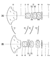
- FIG. 6 is a diagram showing a moving state of each lens group when a zoom operation is performed.
- (A) shows the lens arrangement at the wide end
- a (B) shows the lens arrangement at the tele end.
- the first lens group G1 to the fourth lens group G4 are lens groups that move with respect to the image plane Sim by a zoom operation.
- the fifth lens group G5 is a lens group fixed to the image plane Sim by a zoom operation.
- the first lens group G1 moves along a movement path AL1 by a zoom operation
- the second lens group G2 moves along a movement path AL2 by a zoom operation.
- the third lens group G3 moves along the movement path AL3 by the zoom operation
- the fourth lens group G4 moves along the movement path AL4 by the zoom operation.
- the stop St moves integrally with the second lens group G2.
- the third lens group G3 includes a front group G3a of the third lens group and a rear group G3b of the third lens group.
- the front group G3a of the third lens group is a lens group for correcting field curvature.
- the front group G3a of the third lens group is a lens group that can move independently of the other lens groups. When correcting the field curvature, the front group G3a of the third lens group is moved along the optical axis Z.
- the fourth lens group G4 is a lens group for focusing.
- the fourth lens group G4 is a lens group that can move independently of the other lens groups. When adjusting the focus, the fourth lens group G4 is moved along the optical axis Z.
- the first lens group holding frame 20 is provided with three first lens group driving cam pins 32 on the outer peripheral portion thereof.
- the three first lens group driving cam pins 32 are arranged at equal intervals in the circumferential direction.
- Each of the first lens group driving cam pins 32 is fitted into the first lens group driving cam groove 14A provided in the cam barrel 14 and the first lens group driving straight groove 12A provided in the fixed barrel 12, respectively. .
- the first lens group G1 is held in the fixed barrel 12.
- the cam barrel 14 is rotated by the zoom ring 4
- the first lens group G1 moves along the optical axis Z in the fixed barrel 12.
- the second lens group G ⁇ b> 2 is held in the second lens group holding frame 22 and arranged in the fixed barrel 12.
- the second lens group holding frame 22 is provided with three second lens group driving cam pins 34 on the outer peripheral portion thereof.
- the three second lens group driving cam pins 34 are arranged at equal intervals in the circumferential direction.
- the second lens group driving cam pins 34 are fitted into the second lens group driving cam grooves 14B provided in the cam barrel 14 and the second lens group driving straight grooves 12B provided in the fixed barrel 12, respectively. .
- the second lens group G2 is held in the fixed barrel 12.
- the cam barrel 14 is rotated by the zoom ring 4
- the second lens group G2 moves along the optical axis Z in the fixed barrel 12.
- an aperture unit 30 constituting the aperture St is assembled to the second lens group holding frame 22. Thereby, the stop St is disposed in the fixed barrel 12 and moves together with the second lens group G2.
- the third lens group G ⁇ b> 3 is held in the third lens group holding frame 24 and arranged in the fixed barrel 12.
- the third lens group holding frame 24 includes a third lens group base holding frame 24A and a third lens group movable holding frame 24B held by the third lens group base holding frame 24A.
- the third lens group movable holding frame 24B is movably held in the third lens group base holding frame 24A along the optical axis Z.
- the front group G3a of the third lens group is held by the third lens group movable holding frame 24B.
- the third lens group rear group G3b is held by the third lens group base holding frame 24A.
- the third lens group base holding frame 24A is provided with three third lens group driving cam pins 36 on its outer peripheral portion.
- the three third lens group driving cam pins 36 are arranged at equal intervals in the circumferential direction.
- the third lens group driving cam pins 36 are fitted into the third lens group driving cam grooves 14C provided in the cam barrel 14 and the third lens group driving straight grooves 12C provided in the fixed barrel 12, respectively. .
- the third lens group base holding frame 24 ⁇ / b> A is held in the fixed barrel 12.
- the third lens group base holding frame 24 ⁇ / b> A moves along the optical axis Z in the fixed barrel 12.
- the third lens group base holding frame 24A is an example of a first cylinder
- the third lens group driving cam pin 36 is an example of a first cam pin
- the third lens group driving cam groove 14C is an example of a first cam groove
- the third lens group driving straight groove 12C is an example of a first straight groove.
- first main shaft 48 and a first sub shaft 50 are provided in the third lens group base holding frame 24A.
- the first main axis 48 and the first sub axis 50 are respectively arranged along the optical axis Z. Further, the first main axis 48 and the first sub axis 50 are arranged symmetrically with respect to the optical axis Z (arranged at a position of 180 ° in the circumferential direction). The specific layout of the first main shaft 48 and the first sub shaft 50 will be described later in detail.
- the third lens group movable holding frame 24B includes a first main guide portion 52 that slides along the first main shaft 48 and a first sub guide portion 54 that slides along the first sub shaft 50.
- the third lens group movable holding frame 24B is slidably supported by the first main shaft 48 and the first sub shaft 50 via the first main guide portion 52 and the first sub guide portion 54.
- FIG. 7 is a cross-sectional view showing a support structure of the third lens group movable holding frame and the fourth lens group movable holding frame.
- the first main guide portion 52 has a cylindrical shape and has sliding portions 52A at both ends in the axial direction.
- the sliding portion 52A has an inner diameter corresponding to the outer diameter of the first main shaft 48.
- the sliding portions 52A at both ends slide along the first main shaft 48.
- the first sub-guide portion 54 has a U-shaped groove 54A at the tip. In the first sub guide portion 54, the groove portion 54A slides along the first sub shaft 50.
- the first main guide portion 52 is slidably supported by the first main shaft 48, and the first sub guide portion 54 is slidably supported by the first sub shaft 50. Accordingly, the third lens group base holding frame 24A is movably supported along the optical axis Z.
- the third lens group movable holding frame 24B is an example of a first lens frame.
- the first sub-guide portion 54 is supported by one fulcrum (groove 54A) with respect to the first sub-shaft 50, whereas the first main guide portion 52 is supported by the first main shaft 48. Are supported by two fulcrums (sliding portions 52A at both ends). Therefore, the first main guide portion 52 can more stably support the third lens group movable holding frame 24B than the first sub guide portion 54. The first main guide portion 52 can stably support the third lens group movable holding frame 24B as the distance between the two sliding portions 52A increases. In addition, in the case of such a configuration in which a plurality of sliding parts are supported, the distance between the two outermost sliding parts is a substantial length of the guide part.
- the third lens group movable holding frame 24B is driven by the third lens group front group drive unit 56.
- the third lens group front group drive unit 56 is an example of a first drive unit.
- the third lens group front group drive unit 56 is configured by a moving magnet type (movable magnet type) voice coil motor (Voice Coil Motor: VCM).
- the moving magnet type VCM is a type of VCM in which a magnet moves in a magnetic field generated by a yoke and a coil, and is one of linear actuators.
- the third lens group movable holding frame 24B is provided with a plurality of driving magnets 56A of a moving magnet type VCM and a plurality of inner yokes 56B constituting the third lens group front group drive unit 56.
- the third lens group base holding frame 24A is provided with a driving coil 56C of a moving magnet type VCM and a plurality of outer yokes 56D which constitute the third lens group front group drive unit 56.
- FIG. 8 is a cross-sectional view showing the mounting structure of the front drive unit of the third lens group.
- the driving coil 56C is mounted such that the third lens group movable holding frame 24B moves on the inner periphery thereof.
- the plurality of driving magnets 56A are arranged in two groups. More specifically, the two groups are arranged symmetrically about the optical axis Z (arranged at intervals of 180 ° in the circumferential direction, and are arranged to face each other with the optical axis Z interposed therebetween. ). In the present embodiment, six driving magnets 56A are provided, and the six driving magnets 56A are divided into two groups and arranged. Each group has three driving magnets 56A and is arranged at equal intervals along the peripheral surface of the third lens group movable holding frame 24B.
- the plurality of driving magnets 56A of the VCM constituting the third lens group front group driving section 56 are an example of the first driving magnet.
- the inner yoke 56B is provided corresponding to the driving magnet 56A.
- Each inner yoke 56B is integrated with the corresponding driving magnet 56A and attached to the third lens group movable holding frame 24B.
- the outer yoke 56D is provided corresponding to the inner yoke 56B. Each outer yoke 56D is arranged so as to face the corresponding inner yoke 56B with the driving coil 56C interposed therebetween.
- the third lens group G3 is held in the fixed barrel 12.
- the third lens group G3 moves along the optical axis Z in the fixed barrel 12 (the third lens group front group G3a and the third lens group rear group G3b). Move integrally along the optical axis Z in the fixed cylinder 12).
- the third lens group front group drive section 56 is driven, the third lens group front group G3a moves alone along the optical axis Z (the third lens group front group G3a is independently moved along the optical axis Z). Move along.).
- the field curvature is corrected.
- the fourth lens group G4 is held in the fourth lens group holding frame 26 and arranged in the fixed cylinder 12.
- the fourth lens group holding frame 26 includes a fourth lens group base holding frame 26A, and a fourth lens group movable holding frame 26B held by the fourth lens group base holding frame 26A.
- the fourth lens group movable holding frame 26B is movably held in the fourth lens group base holding frame 26A along the optical axis Z.
- the fourth lens group G4 is held by the fourth lens group movable holding frame 26B.
- the fourth lens group base holding frame 26A is provided with three fourth lens group driving cam pins 38 on the outer peripheral portion thereof.
- the three fourth lens group driving cam pins 38 are arranged at equal intervals in the circumferential direction.
- the fourth lens group driving cam pins 38 are fitted into the fourth lens group driving cam grooves 14D provided in the cam barrel 14 and the fourth lens group driving straight grooves 12D provided in the fixed barrel 12, respectively. .
- the fourth lens group base holding frame 26A is held in the fixed barrel 12.
- the fourth lens group base holding frame 26A moves in the fixed barrel 12 along the optical axis Z.
- the fourth lens group base holding frame 26A is an example of a second cylinder
- the fourth lens group driving cam pin 38 is an example of a second cam pin
- the fourth lens group driving cam groove 14D is an example of a second cam groove
- the fourth lens group driving rectilinear groove 12D is an example of a second rectilinear groove.
- second main shaft 58 and a second sub shaft 60 are provided in the fourth lens group base holding frame 26A.
- the second main axis 58 and the second sub axis 60 are respectively arranged along the optical axis Z.
- the second main shaft 58 and the second sub shaft 60 are arranged symmetrically with respect to the optical axis Z (arranged at a position of 180 ° in the circumferential direction). A specific layout of the second main shaft 58 and the second sub shaft 60 will be described later in detail.
- the fourth lens group movable holding frame 26 ⁇ / b> B includes a second main guide portion 62 that slides along the second main shaft 58 and a second sub guide portion 64 that slides along the second sub shaft 60.
- the fourth lens group movable holding frame 26B is slidably supported by the second main shaft 58 and the second sub shaft 60 via the second main guide portion 62 and the second sub guide portion 64.
- the second main guide portion 62 has a cylindrical shape, and has sliding portions 62A at both ends in the axial direction.
- the sliding portion 62A has an inner diameter corresponding to the outer diameter of the second main shaft 58.
- the sliding portions 62A at both ends of the second main guide portion 62 slide along the second main shaft 58.
- the second sub-guide 64 has a U-shaped groove 64A at the tip.
- the groove portion 64 ⁇ / b> A of the second sub guide portion 64 slides along the second sub shaft 60.
- the fourth lens group movable holding frame 26B In the fourth lens group movable holding frame 26B, the second main guide portion 62 is slidably supported by the second main shaft 58, and the second sub guide portion 64 is slidably supported by the second sub shaft 60. Thereby, the fourth lens group base holding frame 26A is movably supported along the optical axis Z.
- the fourth lens group movable holding frame 26B is an example of a second lens frame.
- the second sub guide portion 64 is supported by one fulcrum (groove 64A) with respect to the second sub shaft 60, while the second main guide portion 62 is supported by the second main shaft 58.
- the second main guide portion 62 can more stably support the fourth lens group movable holding frame 26B than the second sub guide portion 64.
- the second main guide portion 62 can stably support the fourth lens group movable holding frame 26B as the distance between the two sliding portions 62A is increased.
- the fourth lens group movable holding frame 26B is driven by the fourth lens group drive unit 66.
- the fourth lens group driving unit 66 is an example of a second driving unit.
- the fourth lens group drive section 66 is configured by a plurality of moving coil type (moving coil type) voice coil motors (Voice Coil Motor: VCM) 68.
- the moving coil type VCM is a type of VCM in which only a coil moves in a magnetic field generated by a magnet, and is one of linear actuators.
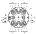
- FIG. 9 is a cross-sectional view showing the mounting structure of the fourth lens group drive unit.
- the plurality of VCMs 68 are divided into two groups and arranged. More specifically, the two groups are arranged symmetrically about the optical axis Z (arranged at intervals of 180 ° in the circumferential direction, and are arranged to face each other with the optical axis Z interposed therebetween. ). In the present embodiment, four VCMs 68 are provided, and the four VCMs 68 are divided into two groups and arranged. Each group has two VCMs 68 and is arranged at predetermined intervals along the peripheral surface of the fourth lens group movable holding frame 26B.
- Each VCM 68 includes a driving coil 68A, a driving magnet 68B, an inner yoke 68C, and an outer yoke 68D.
- the driving coil 68A of each VCM 68 is attached to the fourth lens group movable holding frame 26B.
- the fourth lens group movable holding frame 26B has a coil holding portion 70 on the outer periphery thereof, and the coil holding portion 70 holds a driving coil 68A of each VCM 68.
- each VCM 68 is arranged to face each other with the driving coil 68A interposed therebetween.
- the inner yoke 68C and the outer yoke 68D are integrally formed.
- the inner yoke 68C and the outer yoke 68D which are integrally formed are arranged at predetermined positions with the outer yoke 68D being held by the inner peripheral portion of the fourth lens group base holding frame 26A.
- the driving magnet 68B of each VCM 68 is attached to the inside of the outer yoke 56D and arranged at a predetermined position.
- the driving magnet 68B of each VCM 68 is an example of a plurality of second driving magnets.
- the fourth lens group G4 is held in the fixed barrel 12.
- the fourth lens group G4 moves along the optical axis Z in the fixed barrel 12.
- the fourth lens group drive section 66 is driven, the fourth lens group G4 moves independently along the optical axis Z.
- the focus adjustment is performed by independently moving the fourth lens group G4.
- the third lens group front group G3a and the fourth lens group G4 are moved independently of the other lens groups by the third lens group front group driving unit 56 and the fourth lens group driving unit 66, respectively. Can be. Therefore, the positions of the third lens group front group G3a and the fourth lens group G4 are separately detected.
- the position of the third lens group front group G3a is detected by the third lens group front group position detector 80, and the position of the fourth lens group G4 is detected by the fourth lens group position detector 90. .
- the third lens group front group position detection unit 80 detects the position of the third lens group movable holding frame 24B within the third lens group base holding frame 24A, and detects the position of the third lens group front group G3a. . More specifically, the position of the third lens group movable holding frame 24B with respect to a reference position set in the third lens group base holding frame 24A is detected, and the position of the third lens group front group G3a with respect to the reference position. Is detected.
- the front position detection unit 80 of the third lens group is an example of a first position detection unit.
- the third lens group front group position detecting section 80 includes a position detecting magnet 82 provided in the third lens group movable holding frame 24B and a position detecting magnet 82. And a position detection sensor 84 for detecting a position.
- the position detection sensor 84 is configured by a Hall element that is a magnetic sensor.
- the position detection sensor 84 is provided on the third lens group base holding frame 24A.
- the position detection sensor 84 is disposed at the installation position of the first sub shaft 50 in a cross section orthogonal to the optical axis Z, as shown in FIG. More specifically, they are arranged on a straight line passing through the optical axis Z and the first sub-axis 50. Further, as shown in FIG. 4, the position detection sensor 84 is disposed behind the first sub shaft 50 (on the image surface side) in a cross section parallel to the optical axis Z.
- the position detecting magnet 82 is an example of a first position detecting magnet.
- the position detecting magnet 82 is provided on the third lens group movable holding frame 24B.
- the position detecting magnet 82 is arranged close to the position detecting sensor 84.
- the first sub guide portion 54 in a cross section perpendicular to the optical axis Z, is disposed at the installation position, and is disposed to face the position detection sensor 84 with a predetermined gap. You.
- the position detecting magnet 82 and the position detecting sensor 84 are both arranged on a straight line passing through the optical axis Z and the first sub-axis 50 in a cross section orthogonal to the optical axis Z.
- the position of the position detecting magnet 82 provided in the third lens group movable holding frame 24B is detected by the position detecting sensor 84, so that the third The position of the front lens group G3a is detected.
- the fourth lens group position detecting section 90 detects the position of the fourth lens group movable holding frame 26B in the fourth lens group base holding frame 26A, and detects the position of the fourth lens group G4. More specifically, the position of the fourth lens group movable holding frame 26B with respect to the reference position set in the fourth lens group base holding frame 26A is detected, and the position of the fourth lens group G4 with respect to the reference position is detected. I do.
- the fourth lens group position detector 90 is an example of a second position detector.
- the fourth lens group position detecting section 90 includes a reference position detecting section 92 that detects that the fourth lens group G4 is located at the reference position, a displacement amount detecting section 94 that detects a displacement amount of the fourth lens group G4, It consists of.
- the fourth lens group position detecting section 90 detects that the fourth lens group G4 is located at the reference position by the reference position detecting section 92, and detects the amount of displacement from the reference position by the displacement amount detecting section 94. The position of the four lens group G4 is detected.
- the reference position detection unit 92 is composed of a light shielding plate 92A and a photo interrupter 92B.
- the light shielding plate 92A is provided on the first main guide portion 52, and the photo interrupter 92B is provided on the fourth lens group base holding frame 26A.
- the reference position detection unit 92 detects that the fourth lens group G4 is located at the reference position by detecting the light blocking plate 92A with the photo interrupter 92B. Therefore, the light shielding plate 92A and the photo interrupter 92B are installed such that the light shielding plate 92A is detected at the timing when the fourth lens group G4 is located at the reference position.
- the displacement amount detection unit 94 includes a magnetic scale 94A and an MR sensor (Magneto Resistive Sensor) for detecting the N pole and the S pole of the magnetic scale 94A. 94B.
- MR sensor Magnetic Resistive Sensor
- the magnetic scale 94A is an example of the second position detecting magnet.
- the magnetic scale 94A has a bar shape, and has a structure in which N poles and S poles are magnetized at a constant pitch along the longitudinal direction.
- the magnetic scale 94A is provided on the second main guide portion 62, and is arranged along the moving direction of the fourth lens group G4. That is, they are arranged along the optical axis Z.
- the MR sensor 94B is provided in the fourth lens group base holding frame 26A, as shown in FIGS.
- the MR sensor 94B is arranged close to the magnetic scale 94A. More specifically, as shown in FIG. 9, in a cross section orthogonal to the optical axis Z, it is arranged at the installation position of the second main guide portion 62 and is arranged to face the magnetic scale 94A with a predetermined gap. You.
- the magnetic scale 94A and the MR sensor 94B are both arranged on a straight line passing through the optical axis Z and the second main axis 58 in a cross section orthogonal to the optical axis Z.
- the light blocking plate 92A provided in the second main guide section 62 is detected by the photo interrupter 92B, so that the fourth lens group G4 is located at the reference position. Is detected. Further, the displacement of the fourth lens group G4 is detected by detecting the displacement of the second main guide portion 62 via the magnetic scale 94A with the MR sensor 94B.
- the photointerrupter 92B detects that the fourth lens group G4 is located at the reference position, and the MR sensor 94B detects the amount of displacement from the reference position, thereby detecting the position of the fourth lens group G4 with respect to the reference position. .
- the third lens group front group G3a is movably supported by the first main shaft 48 and the first sub shaft 50 via the first main guide portion 52 and the first sub guide portion 54.
- the fourth lens group G4 is movably supported by the second main shaft 58 and the second sub shaft 60 via the second main guide portion 62 and the second sub guide portion 64.
- the length of the guide portion (main guide portion) with respect to the main axis is long, so that the lens can be stably moved. .
- the third lens group G3 and the fourth lens group G4 are adjacent to each other on the optical axis Z.
- the first main axis 48 and the first sub-axis 50 for guiding the movement of the front group G3a of the third lens group and the second main axis 58 and the second sub-axis 60 for guiding the movement of the fourth lens group G4 are coaxial. If it is arranged above, the length of the main shaft is restricted, and the length of the guide portion cannot be sufficiently secured.
- the first main axis 48 and the first sub-axis 50 that guide the movement of the front group G3a of the third lens group, and the second main axis 58 and the second sub-axis 60 that guide the movement of the fourth lens group G4 are circumferentially aligned.
- the driving magnets of the VCM that drive the third lens group front group G3a and the fourth lens group G4 are arranged asymmetrically with respect to the sensor. As a result, there is a problem that the accuracy of the sensor that detects the position using magnetism is reduced.
- the drive systems and the position detection units of the front group G3a of the third lens group and the fourth lens group G4 are laid out as follows.
- a second main axis 58 and a second auxiliary axis 60 that guide the movement of the fourth lens group G4 are arranged on a straight line L passing through the optical axis Z.
- the second main shaft 58 and the second sub shaft 60 are arranged parallel to each other with the optical axis Z interposed therebetween.
- the term “on a straight line” includes not only a case where the centers of the respective axes are completely arranged on the same straight line but also a case where the centers of the respective axes are recognized as being substantially arranged on the same straight line. In other words, the case where they are arranged on substantially the same straight line is included.
- the first main axis 48 and the first sub axis 50 for guiding the movement of the front group G3a of the third lens group are formed by the straight line L (the optical axis Z And a straight line passing through the second main shaft 58 and the second sub shaft 60).
- the first main shaft 48 and the first sub shaft 50 are arranged in parallel with each other with the optical axis Z interposed therebetween.
- the term “on a straight line” includes not only a case where the centers of the respective axes are completely arranged on the same straight line but also a case where the centers of the respective axes are recognized as being substantially arranged on the same straight line. In other words, the case where they are arranged on substantially the same straight line is included.
- the first main shaft 48 and the first sub shaft 50 are arranged on the inner diameter side of the second main shaft 58 and the second sub shaft 60, and As shown in FIG. 4, the first main shaft 48 and the second main shaft 58 are arranged so as to overlap.
- the first main axis 48, the second main axis 58, the first sub axis 50, and the second sub axis 60 are arranged on the same straight line L.
- the length of both main axes can be increased. .
- the length of both main guide portions can be secured, and the lens guided by each axis can be stably moved.
- the position detection sensor 84 for detecting the position of the front group G3a of the third lens group is arranged at the installation position of the first sub shaft 50 and is arranged on the straight line L.
- an MR sensor 94B for detecting the position of the fourth lens group G4 is arranged at the installation position of the second main guide portion 62, and is arranged on the straight line L.
- “on a straight line” here includes a range recognized as being substantially arranged on a straight line. That is, a case where the light emitting device is arranged substantially on the straight line L is included.
- the third lens group front group driving section 56 for driving the third lens group front group G3a is configured by a VCM, and the plurality of driving magnets 56A (the first driving section) configuring the VCM.
- the straight line L passes through the optical axis Z and has the first main axis 48, the second main axis 58,
- a plurality of driving magnets 56A are symmetrically arranged with respect to a straight line passing through the first sub shaft 50 and the second sub shaft 60).
- the term “symmetry” includes a range that is recognized as being substantially symmetrically arranged in addition to being completely symmetrically arranged. That is, there is a case where they are arranged substantially symmetrically.
- the fourth lens group driving unit 66 for driving the fourth lens group G4 includes the plurality of VCMs 68, and includes the plurality of driving magnets 68B (the second driving Are arranged symmetrically about the optical axis Z.
- the straight line L passeses through the optical axis Z and has the first main axis 48, the second main axis 58
- the plurality of driving magnets 68B are arranged symmetrically with respect to a straight line passing through the first sub shaft 50 and the second sub shaft 60).
- the term “symmetry” includes a range that is recognized as being substantially symmetrically arranged in addition to being completely symmetrically arranged. That is, there is a case where they are arranged substantially symmetrically.
- the position detection sensor 84 and the MR sensor 94B arranged on the straight line L can be symmetrically arranged. Accordingly, even when the position detection sensor (Hall element) 84 and the MR sensor 94B, which are magnetic sensors, are installed at the position of the main shaft or the sub shaft, the position can be detected with high accuracy.
- the first main axis 48, the first sub axis 50, the second main axis 58, and the second sub axis 60 are on the straight line L passing through the optical axis Z.
- the first main shaft 48 and the first sub shaft 50 are arranged on the inner diameter side of the second main shaft 58 and the second sub shaft 60. This makes it possible to stably support a movable lens group with a compact configuration. That is, by disposing the positions of the first main shaft 48 and the first sub shaft 50 in the radial direction with respect to the second main shaft 58 and the second sub shaft 60, the size in the optical axis direction can be enlarged as a whole.
- the lengths of the first main shaft 48 and the second main shaft 58 can be secured. Thereby, the lengths of the first main guide portion 52 and the second main guide portion 62 can be secured, and the third lens group front group G3a and the fourth lens group G4 can be stably supported.
- driving magnets for driving each lens group are symmetrically arranged with respect to a straight line L passing through the optical axis Z. Accordingly, even when the position detection sensor (Hall element) 84 and the MR sensor 94B, which are magnetic sensors, are installed at the position of the main shaft or the sub shaft, the position can be detected with high accuracy.
- the interchangeable lens 1 of the present embodiment it is possible to support the lens groups (the third lens group front group G3a and the fourth lens group G4) that are stably movable while making the whole compact, and with high accuracy.
- the position of the movable lens group can be detected.
- FIG. 10 is a block diagram showing an electrical configuration of the interchangeable lens.
- the interchangeable lens 1 includes a third lens group front group driving unit 56 that drives the third lens group front group G3a, a third lens group front group position detection unit 80 that detects the position of the third lens group front group G3a, and a fourth The fourth lens group driving unit 66 that drives the lens group G4, the fourth lens group position detecting unit 90 that detects the position of the fourth lens group G4, the diaphragm driving unit 112 that drives the diaphragm St, and the temperature inside the interchangeable lens 1
- a temperature control unit 114 for detecting, a focus operation detection unit 116 for detecting a focus operation, a zoom setting detection unit 118 for detecting a zoom operation, an aperture setting detection unit 120 for detecting an aperture operation, and overall control of the entire operation of the interchangeable lens 1.
- a lens control unit 110 that performs the operation.
- the third lens group front group drive section 56 moves the third lens group front group G3a along the optical axis Z in response to a command from the lens control section 110.
- the third lens group front group position detecting section 80 detects the position of the third lens group front group G3a, and outputs the detection result to the lens control section 110.
- the fourth lens group drive section 66 moves the fourth lens group G4 along the optical axis Z according to a command from the lens control section 110.
- the fourth lens group position detecting section 90 includes the reference position detecting section 92 and the displacement detecting section 94 as described above.
- the reference position detection unit 92 detects that the fourth lens group G4 is located at the reference position.
- the displacement amount detection unit 94 detects the displacement amount of the fourth lens group G4.
- the reference position detector 92 detects that the fourth lens group G4 is located at the reference position, and the displacement detector 94 detects the amount of displacement from the reference position, thereby detecting the position of the fourth lens group G4.
- the aperture driving unit 112 is configured by an actuator such as a motor, and is provided in the aperture unit 30.
- the aperture drive unit 112 enlarges or reduces the aperture St in response to a command from the lens control unit 110.
- the temperature detection unit 114 detects the temperature inside the interchangeable lens 1 and outputs the detection result to the lens control unit 110.
- the temperature detection unit 114 is provided in, for example, the aperture unit 30.
- the focus operation detection unit 116 detects the amount of rotation operation of the focus ring 3 and outputs the detection result to the lens control unit 110.
- the lens control unit 110 detects a focus operation amount based on an output from the focus operation detection unit 116.
- the zoom setting detection unit 118 detects the setting position of the zoom ring 4 and outputs the detection result to the lens control unit 110.
- the lens control unit 110 detects a zoom set value (focal length) based on the output from the zoom setting detection unit 118.
- the aperture setting detection unit 120 detects the setting position of the aperture ring 5 and outputs the detection result to the lens control unit 110.
- the lens control unit 110 detects an aperture setting value (aperture value) based on an output from the aperture setting detection unit 120.
- the lens control unit 110 controls the operation of each unit based on the operation of the focus ring 3, the zoom ring 4, and the aperture ring 5. Specifically, when the manual focus is set, the fourth lens group drive section 66 is driven based on the amount of rotation of the focus ring 3 to move the fourth lens group G4. Further, based on the setting of the zoom ring 4, the third lens group front group driving unit 56 and the fourth lens group driving unit 66 are driven to move the third lens group front group G3a and the fourth lens group G4 to predetermined positions. Let it. Thereby, the curvature of field based on the zoom position is corrected. Further, based on the setting of the aperture ring 5, the aperture driving unit 112 is driven to set the aperture St to a predetermined aperture (aperture value).
- the lens control unit 110 controls the operation of each unit according to a command from a camera on which the interchangeable lens 1 is mounted.
- the fourth lens group drive section 66 is driven based on autofocus information from the camera to move the fourth lens group G4 to a predetermined position.
- the aperture driving unit 112 is driven based on the aperture setting information from the camera, and the aperture St is set to a predetermined opening amount.
- the lens control unit 110 communicates with the camera control unit 130 of the camera, and receives a drive command for each unit from the camera control unit 130. Further, the control unit 130 transmits zoom setting information, aperture setting information, focus position information, and the like to the camera control unit 130. Communication between the lens control unit 110 and the camera control unit 130 is performed via a terminal 16 ⁇ / b> A provided on the mount 16.
- the lens control section 110 drives the third lens group front group drive section 56 based on the temperature detected by the temperature detection section 114 to move the third lens group front group G3a to a predetermined position. Thereby, the field curvature based on the temperature change is corrected.
- the lens control unit 110 is composed of, for example, a computer having a CPU (Central Processing Unit), a ROM (Read Only Memory), and a RAM (Random Access Memory), and executes a predetermined program. And implement various control functions.
- a computer having a CPU (Central Processing Unit), a ROM (Read Only Memory), and a RAM (Random Access Memory), and executes a predetermined program. And implement various control functions.
- CPU Central Processing Unit
- ROM Read Only Memory
- RAM Random Access Memory
- the position of the fourth lens group G4 is detected by a combination of the photo interrupter and the MR sensor.
- the structure of detecting the position of the fourth lens group G4 is not limited to this. Not something.
- the configuration may be such that detection is performed by a Hall element.
- the senor to be used is selected in consideration of the movement stroke of the lens.
- the position may be detected using a Hall element, and for a lens group having a relatively long moving stroke, the position may be detected using an MR sensor.
- the Hall element can detect an absolute position (a position based on a predetermined reference position), so that the configuration of the position detection unit can be made compact.
- the moving stroke of the third lens group front group G3a is set shorter than the moving stroke of the fourth lens group G4.
- the position of the third lens group front group G3a is detected by the Hall element
- the position of the fourth lens group G4 is detected by the MR sensor.
- a position detection unit is disposed on the sub-axis side, but a configuration in which a position detection unit is disposed on the main shaft side may be employed.
- a configuration may be adopted in which a magnet for position detection is arranged on the first main guide portion 52 and the position of the magnet for position detection is detected by a Hall element.
- the position can be detected by the main guide portion that can move more stably, and the position can be detected with higher accuracy.
- the position detecting magnet 82 by arranging the position detecting magnet 82 on the side of the first sub-guide portion 54, an empty space (space behind the first sub-guide portion 54) is effectively utilized.
- the position detection unit can be arranged. Thereby, the whole configuration can be made compact.
- the configuration for detecting the position of the fourth lens group G4 may be such that the position detection unit is arranged on the sub-axis side.
- the position detection unit is disposed on the sub-axis side.
- the position of the fourth lens group G4 is detected by using the MR sensor 94B as in the above-described embodiment, by providing the magnetic scale 94A in the second main guide portion 62, the position can be accurately determined. Can be detected. That is, since the second main guide portion 62 is the portion that is most stable in movement, by providing the magnetic scale 94A in this portion, the magnetic scale 94A can be moved stably. Thereby, the position can be detected with high accuracy.
- the main axis of the front group G3a of the third lens group and the sub-axis of the fourth lens group G4 may be arranged, and the sub-axis of the front group G3a of the third lens group and the main axis of the fourth lens group G4 may be arranged below.
- the main axis and the sub-axis of the front lens group (the third lens group front group G3a) in the optical axis direction are the same as the main axis and the sub-axis of the rear lens group (the fourth lens group G4).
- the structure is arranged on the inner diameter side
- the main axis and the sub-axis of the rear lens group may be arranged on the inner diameter side with respect to the main axis and the sub-axis of the front lens group. It is preferable that the main axis and the sub-axis of which lens group are arranged on the inner diameter side are determined in consideration of the movement stroke, weight, and the like of each lens group.
- the moving stroke of the third lens group front group G3a is set shorter than the moving stroke of the fourth lens group G4, and the main axis and the sub-axis of the third lens group front group G3a are The fourth lens group G4 is disposed on the inner diameter side of the main axis and the sub axis. Thereby, the structure of the guide of the third lens group front group G3a disposed inside can be relatively reduced in size.
- the main axis and the sub-axis of the lighter lens group are arranged on the inner diameter side.
- the weight here is the weight of the movable holding frame (the third lens group movable holding frame 24B and the fourth lens group movable holding frame 26B) holding the lens.
- the structure of the inner guide can be relatively reduced in size. This also makes it possible to make the overall configuration compact.
- the third lens group front group G3a is lighter than the fourth lens group G4, and the main axis and the sub axis of the third lens group front group G3a are the same as those of the fourth lens group G4. It is arranged on the inner diameter side of the main shaft and the counter shaft. Thereby, the structure of the guide of the third lens group front group G3a disposed inside can be relatively reduced in size.
- the length of the main axis arranged inside is relatively shorter than the length of the main axis arranged outside. Therefore, the structure of the inner guide can be made more compact.
- the third lens group front group drive unit 56 is configured by a moving magnet type VCM, but may be configured by a moving coil type VCM.
- the fourth lens group drive unit 66 is configured by a moving coil type VCM, but may be configured by a moving magnet type VCM.
- the driving unit of the third lens group front group G3a can be reduced in size by driving the third lens group front group G3a with a moving magnet type VCM as in the above embodiment. This is particularly effective when the main and sub axes of the front group G3a of the third lens group are arranged on the inner diameter side as in the above-described embodiment.
- the weight of the movable portion of the fourth lens group G4 can be reduced. Thereby, the fourth lens group G4 can be driven at a higher speed.
- Each drive unit may be constituted by an electromagnetic actuator other than the VCM (an actuator which uses a magnet and a coil as main components and is driven using an electromagnetic force).
- the third lens group movable holding frame 24B as the first lens frame and the fourth lens group movable holding frame 26B as the second lens frame move by zooming.
- the present invention can be applied to a lens barrel in which the first lens frame and the second lens frame do not move by zooming. Further, the present invention can be applied to a lens barrel in which one of the first lens frame and the second lens frame moves by zooming.
- the first main axis and the second main axis do not always need to be arranged so as to overlap in the entire zoom range. In a state where the first lens frame and the second lens frame are closest to each other, at least a part of the first lens frame and the second lens frame need only overlap.
- the field curvature is corrected by moving the third lens group movable holding frame 24B as the first lens frame, and the focal point is moved by moving the fourth lens group movable holding frame 26B as the second lens frame.
- the application of moving each lens frame is not limited to this.
- the present invention can also be applied to a case where the first lens frame and the second lens frame are individually moved to adjust the focus (so-called floating focus).
- the present invention is also applicable to a lens barrel incorporated in an optical device.
- the present invention can be applied to a lens barrel of a camera with an integrated lens.
- the present invention can be applied to optical devices other than cameras (for example, projectors, microscopes, telescopes, etc.).
- the camera can be applied not only to a still camera such as a digital camera and a silver halide camera but also to a video camera, a television camera, a cine camera and the like.
Landscapes
- Physics & Mathematics (AREA)
- General Physics & Mathematics (AREA)
- Optics & Photonics (AREA)
- Nonlinear Science (AREA)
- Engineering & Computer Science (AREA)
- General Engineering & Computer Science (AREA)
- Lens Barrels (AREA)
- Adjustment Of Camera Lenses (AREA)
Abstract
コンパクトな構成で可動するレンズ群を安定して支持でき、かつ、可動するレンズ群の位置を正確に検出できるレンズ鏡胴を提供する。光軸(Z)と直交する断面において、光軸(Z)を通る直線上に、第3レンズ群前群(G3a)の移動をガイドする第1主軸(48)及び第1副軸(50)と、第4レンズ群(G4)の移動をガイドする第2主軸(58)及び第2副軸(60)と、第3レンズ群前群(G3a)の位置を検出するためのホール素子(84)と、第4レンズ群(G4)の位置を検出するためのMRセンサ(94B)と、が配置される。第1主軸(48)及び第1副軸(50)は、第2主軸(58)及び第2副軸(60)よりも内径側に配置される。第1主軸(48)及び第2主軸(58)は、光軸の方向において、オーバーラップして配置される。各レンズ群の駆動部は、複数の駆動用マグネットが前記直線に対して対称に配置される。
Description
本発明は、レンズ鏡胴に係り、特に、複数のレンズ群を独立して駆動可能なレンズ鏡胴に関する。
鏡胴内に複数のリニアアクチュエータを備えることにより、複数のレンズ群を独立して駆動可能なレンズ鏡胴が知られている。
たとえば、特許文献1には、鏡胴内に2つのボイスコイルモータ(Voice Coil Motor;VCM)を備え、各VCMによって、2つのレンズ群を独立して駆動するレンズ鏡胴が記載されている。この特許文献1に記載のレンズ鏡胴では、2つのレンズ群を共通の主軸及び共通の副軸に沿って移動自在に支持する構成としている。
また、特許文献2には、2つのVCMによって、2つのレンズ群を独立して駆動する構成のレンズ鏡胴において、2つのレンズ群を共通の副軸に沿って移動自在に支持し、かつ、個別に用意した主軸に沿って移動自在に支持する構成が記載されている。この特許文献2に記載のレンズ鏡胴において、個別の主軸は、光軸を中心とする同一円周上に配置される。すなわち、周方向にずらして配置される。
レンズ群をVCM等のリニアアクチュエータで駆動する場合において、レンズ群を所望の位置に正確かつスムーズに移動させるためには、主軸に対してレンズ群を安定的に支持する必要がある。このためには、主軸に対するレンズ群側の摺動部の長さ(主軸に沿って摺動する部分の長さ)を十分に確保する必要がある。
しかしながら、特許文献1のように、2つのレンズ群が共通の主軸に沿って移動する構成のレンズ鏡胴は、各レンズ群の可動範囲が制限されるといった欠点、及び、各レンズ群の摺動部の長さを長くすると、鏡胴の全長が拡大されるといった欠点などがある。
一方、特許文献2のように、各レンズ群の主軸の位置を周方向にずらして配置すると、次のような欠点がある。レンズ群をVCM等のリニアアクチュエータで駆動する場合、各レンズ群の位置が検出される。位置検出には、一般にホール素子、磁気抵抗効果素子(Magneto Resistive Sensor;MRセンサ)等の磁気センサが使用される。また、磁気センサは、移動の際の安定性の高い主軸(又は副軸)の位置に配置される。特許文献2のように、各レンズ群の主軸の位置を周方向にずらして配置すると、主軸(又は副軸)の位置に磁気センサを配置した場合に、磁気センサが各レンズ群を駆動するVCMの駆動用マグネットに対して非対称な位置に配置される。磁気センサは、磁界による位置検出を行うため、VCMの駆動用マグネットに対して非対称な位置に配置されると、検出精度が低下するという欠点がある。
本発明は、このような事情に鑑みてなされたもので、コンパクトな構成で可動するレンズ群を安定して支持でき、かつ、可動するレンズ群の位置を正確に検出できるレンズ鏡胴を提供することを目的とする。
上記課題を解決するための手段は、次のとおりである。
(1)光軸を挟んで互いに平行に配置される第1主軸及び第1副軸と、光軸を挟んで互いに平行に配置される第2主軸及び第2副軸と、第1主軸に沿って摺動する第1主ガイド部及び第1副軸に沿って摺動する第1副ガイド部を備えた第1レンズ枠と、第2主軸に沿って摺動する第2主ガイド部及び第2副軸に沿って摺動する第2副ガイド部を備えた第2レンズ枠と、複数の第1駆動用マグネットを備え、第1レンズ枠を駆動する第1駆動部と、複数の第2駆動用マグネットを備え、第2レンズ枠を駆動する第2駆動部と、第1レンズ枠に備えられた第1位置検出用マグネットの位置を検出して、第1レンズ枠の位置を検出する第1位置検出部と、第2レンズ枠に備えられた第2位置検出用マグネットの位置を検出して、第2レンズ枠の位置を検出する第2位置検出部と、を備え、第1主軸及び第1副軸は、光軸と直交する断面において、第2主軸及び第2副軸を通る直線上に配置され、かつ、第2主軸及び第2副軸よりも内径側に配置され、第1主軸及び第2主軸は、光軸の方向において、少なくとも一部がオーバーラップして配置され、第1位置検出部及び第2位置検出部は、光軸と直交する断面において、第2主軸及び第2副軸を通る直線上に配置され、複数の第1駆動用マグネット及び複数の第2駆動用マグネットは、光軸と直交する断面において、第2主軸及び第2副軸を通る直線に対して対称に配置される、レンズ鏡胴。
本態様によれば、第1レンズ枠及び第2レンズ枠が、第1駆動部及び第2駆動部によって独立して駆動される。また、第1位置検出部及び第2位置検出部によって、各々個別に位置が検出される。
第1レンズ枠は、第1主軸及び第1副軸に沿って移動自在に支持され、第2レンズ枠は、第2主軸及び第2副軸に沿って移動自在に支持される。第1レンズ枠の移動をガイドする第1主軸及び第1副軸は、光軸を挟んで互いに平行に配置される。また、第2レンズ枠の移動がガイドする第2主軸及び第2副軸は、光軸を挟んで互いに平行に配置される。したがって、第1レンズ枠の移動をガイドする第1主軸及び第1副軸並びに第2レンズ枠の移動をガイドする第2主軸及び第2副軸は、互いに平行に配置され、かつ、光軸に沿って配置される。更に、これらの軸は、次のように配置される。すなわち、第1主軸及び第1副軸は、光軸と直交する断面において、第2主軸及び第2副軸を通る直線上に配置され、かつ、第2主軸及び第2副軸よりも内径側に配置される。また、第1主軸及び第2主軸は、光軸の方向において、少なくとも一部がオーバーラップして配置される。これにより、コンパクトな構成で可動するレンズ群を安定して支持できる。すなわち、第1主軸及び第1副軸の位置を第2主軸及び第2副軸に対して、径方向にずらして配置することにより、全体として、光軸方向のサイズを拡大させずに、第1主軸及び第2主軸の長さを確保できる。これにより、第1主ガイド部及び第2主ガイド部の長さを確保でき、第1レンズ枠及び第2レンズ枠を安定して支持できる。
また、第1レンズ枠の位置を検出する第1位置検出部及び第2レンズ枠の位置を検出する第2位置検出部、並びに、複数の第1駆動用マグネット及び複数の第2駆動用マグネットは、次のように配置される。すなわち、第1位置検出部及び第2位置検出部は、光軸と直交する断面において、第2主軸及び第2副軸を通る直線上に配置される。また、複数の第1駆動用マグネット及び複数の第2駆動用マグネットは、光軸と直交する断面において、第2主軸及び第2副軸を通る直線に対して対称に配置される。これにより、第1駆動用マグネット及び第2駆動用マグネットに対して、第1位置検出部及び第2位置検出部を対称に配置でき、第1レンズ枠及び第2レンズ枠の位置を精度よく検出できる。
なお、主軸及び副軸の区別は、次のとおりである。すなわち、レンズ枠をより安定して支持する側の軸が主軸とされる。したがって、主軸及び副軸の区別は、主ガイド部及び副ガイド部との関係で定まる。レンズ枠をより安定してガイドする側のガイド部が主ガイド部であり、主ガイド部が摺動する軸が主軸となる。ガイド部は、摺動する方向の長さが長い方が、より安定してレンズ枠をガイドできる。したがって、摺動する方向の長さが長い方が主ガイド部とされる。
(2)第1位置検出用マグネットが、第1副ガイド部の側に備えられ、第2位置検出用マグネットが、第2主ガイド部の側に備えられる、上記(1)のレンズ鏡胴。
本態様によれば、第2位置検出部に対して相対的に内側に配置される第1位置検出部の第1位置検出用マグネットが、第1副ガイド部の側に備えられる。また、第1位置検出部に対して相対的に外側に配置される第2位置検出部の第2位置検出用マグネットが、第2主ガイド部の側に備えられる。上記のように、主ガイド部は、構造上、副ガイド部よりも大型化する。第2位置検出部よりも内側に位置する第1位置検出部を、主ガイド部(第1主ガイド部)の側ではなく副ガイド部(第1副ガイド部)の側に配置することにより、径方向のコンパクト化ができる。
(3)第2位置検出用マグネットが、第2主ガイド部に備えられる、上記(2)のレンズ鏡胴。
本態様によれば、第1位置検出部に対して相対的に外側に配置される第2位置検出部の第2位置検出用マグネットが、第2主ガイド部に備えられる。主ガイド部の部分は、最も安定して移動する部分であるので、この主ガイド部に第2位置検出用マグネットを備えることにより、第2レンズ枠の位置を精度よく検出できる。
(4)第1レンズ枠の移動ストロークが、第2レンズ枠の移動ストロークよりも短い、上記(1)から(3)のいずれか一のレンズ鏡胴。
本態様によれば、移動ストロークの短い方のレンズ枠(第1レンズ枠)が、内側に配置される主軸(第1主軸)及び副軸(第1副軸)でガイドされる。これにより、内側のガイドの構造を相対的に小型化でき、全体をよりコンパクト化できる。
(5)第1位置検出部が、ホール素子で構成され、第2位置検出部が、磁気抵抗効果素子で構成される、上記(4)のレンズ鏡胴。
本態様によれば、第1レンズ枠の位置を検出する第1位置検出部がホール素子で構成され、第2レンズ枠の位置を検出する第2位置検出部が磁気抵抗効果素子で構成される。すなわち、移動ストロークの短い方のレンズ枠(第1レンズ枠)の位置をホール素子で検出し、移動ストロークの長い方のレンズ枠(第2レンズ枠)の位置を磁気抵抗効果素子で検出するように構成される。第1レンズ枠は、内側に配置される主軸(第1主軸)及び副軸(第1副軸)でガイドされるので、その位置をホール素子で検出する構成とすることにより、全体の構成をよりコンパクト化できる。
(6)レンズを保持した状態の第1レンズ枠の重量が、レンズを保持した状態の第2レンズ枠の重量よりも軽い、上記(1)から(5)のいずれか一のレンズ鏡胴。
本態様によれば、重量が軽い方のレンズ枠(第1レンズ枠)が、内側に配置される主軸(第1主軸)及び副軸(第1副軸)でガイドされる。これにより、各レンズ枠を安定して支持しつつ、内側のガイドの構造を相対的に小型化できる。また、これにより、全体をよりコンパクト化できる。
(7)第1主軸の長さが、第2主軸の長さよりも短い、上記(6)のレンズ鏡胴。
本態様によれば、重量が軽い方のレンズ枠(第1レンズ枠)をガイドする主軸(第1主軸)を、重量が重い方のレンズ枠(第2レンズ枠)の主軸(第2主軸)よりも短くできる。これにより、各レンズ枠を安定して支持しつつ、内側のガイドの構造をより相対的に小型化できる。また、これにより、全体をよりコンパクト化できる。
(8)第1駆動部が、ムービングマグネット型のボイスコイルモータで構成される、上記(1)から(7)のいずれか一のレンズ鏡胴。
本態様によれば、第1駆動部が、ムービングマグネット型のボイスコイルモータで構成される。したがって、第1駆動部は、第1レンズ枠に駆動マグネット(第1駆動用マグネット)が備えられる。これにより、内側の駆動部(第1駆動部)を相対的に小型化でき、全体をよりコンパクト化できる。
(9)第2駆動部が、ムービングコイル型のボイスコイルモータで構成される、上記(1)から(8)のいずれか一のレンズ鏡胴。
本態様によれば、第2駆動部が、ムービングコイル型のボイスコイルモータで構成される。したがって、第2駆動部は、第2レンズ枠に駆動用のコイルが備えられる。これにより、第2レンズ枠を軽量化できる。また、これにより、高速で安定した駆動が可能になる。
(10)第1主軸及び第1副軸を備え、第1レンズ枠を保持する第1筒と、第2主軸及び第2副軸を備え、第2レンズ枠を保持する第2筒と、第1筒及び第2筒の少なくとも一方を光軸に沿って移動させる駆動部と、を更に備えた上記(1)から(9)のいずれか一のレンズ鏡胴。
本態様によれば、光軸に沿って相対的に移動する第1筒及び第2筒が備えられる。第1レンズ枠は第1筒に保持され、第1筒に対して相対的に移動する。また、第2レンズ枠は第2筒に保持され、第2筒に対して相対的に移動する。なお、駆動部の動力は問わない。したがって、手動でもよい。
(11)駆動部は、第1直進溝及び第2直進溝を備えた固定筒と、第1カム溝及び第2カム溝を備え、固定筒に嵌合するカム筒と、第1筒に備えられ、第1直進溝及び第1カム溝に嵌合する第1カムピンと、第2筒に備えられ、第2直進溝及び第2カム溝に嵌合する第2カムピンと、を備え、カム筒を固定筒に対して相対的に回転させることにより、第1筒及び第2筒を光軸に沿って移動させる、上記(10)のレンズ鏡胴。
本態様によれば、駆動部が、いわゆるカム機構で構成され、カム筒を固定筒に対して相対的に回転させることにより、第1筒及び第2筒が相対的に移動する。
本発明によれば、コンパクトな構成で可動するレンズ群を安定して支持でき、かつ、可動するレンズ群の位置を正確に検出できる。
以下、添付図面に従って本発明を実施するための好ましい形態について詳説する。
ここでは、本発明をレンズ交換式カメラの交換レンズに適用した場合を例に説明する。
図1は、本発明が適用された交換レンズの一実施形態を示す側面断面図である。図2は、図1の2-2断面図である。図3は、図1の3-3断面図である。図4は、図2及び図3における4-4断面図である。なお、図1は、図2及び図3における1-1断面図に相当する。また、図1は、ワイド端での側面断面図である。図5は、図1に示す交換レンズのテレ端での側面断面図である。
本実施の形態の交換レンズ1は、いわゆるズームレンズであり、手動によるズーム操作によって、焦点距離が連続的に変化する。交換レンズ1は、主として、外装体2と、外装体2に収容される鏡胴本体10と、で構成される。
[外装体]
外装体2は、円筒形状を有し、その内側に鏡胴本体10を収容して、鏡胴本体10の外周部を覆う。外装体2には、フォーカスの操作部材であるフォーカスリング3、ズームの操作部材であるズームリング4及び絞りの操作部材である絞りリング5が備えられる。
外装体2は、円筒形状を有し、その内側に鏡胴本体10を収容して、鏡胴本体10の外周部を覆う。外装体2には、フォーカスの操作部材であるフォーカスリング3、ズームの操作部材であるズームリング4及び絞りの操作部材である絞りリング5が備えられる。
[鏡胴本体]
鏡胴本体10は、レンズ鏡胴の一例である。鏡胴本体10は、固定筒12及びカム筒14を有する。カム筒14は、固定筒12の内周部に嵌合されて、固定筒12の内周部を周方向に回転自在に保持される。
鏡胴本体10は、レンズ鏡胴の一例である。鏡胴本体10は、固定筒12及びカム筒14を有する。カム筒14は、固定筒12の内周部に嵌合されて、固定筒12の内周部を周方向に回転自在に保持される。
固定筒12は、その後端部(像面側の端部)にマウント16を有する。マウント16は、いわゆるバヨネットマウントで構成される。
カム筒14は、図示しない連結部材を介してズームリング4と連結される。したがって、ズームリング4を回転させると、その回転に連動して、カム筒14も回転する。
《レンズ構成》
固定筒12の内部には、複数のレンズが配置される。具体的には、光軸Zに沿って、物体側から順に、第1レンズ群G1、第2レンズ群G2、第3レンズ群G3、第4レンズ群G4及び第5レンズ群G5が配置される。各レンズ群は、少なくとも1枚のレンズで構成される。
固定筒12の内部には、複数のレンズが配置される。具体的には、光軸Zに沿って、物体側から順に、第1レンズ群G1、第2レンズ群G2、第3レンズ群G3、第4レンズ群G4及び第5レンズ群G5が配置される。各レンズ群は、少なくとも1枚のレンズで構成される。
また、固定筒12の内部には、絞りStが配置される。絞りStは、第1レンズ群G1と第2レンズ群G2との間に配置される。
図6は、ズーム操作した場合の各レンズ群の移動状態を示す図である。同図において、(A)は、ワイド端でのレンズ配置を示しており、A(B)は、テレ端でのレンズ配置を示している。
同図に示すように、第1レンズ群G1から第4レンズ群G4は、ズーム操作により、像面Simに対して移動するレンズ群である。第5レンズ群G5は、ズーム操作により、像面Simに対して固定のレンズ群である。第1レンズ群G1は、ズーム操作により移動軌跡AL1に沿って移動し、第2レンズ群G2は、ズーム操作により移動軌跡AL2に沿って移動する。また、第3レンズ群G3は、ズーム操作により移動軌跡AL3に沿って移動し、第4レンズ群G4は、ズーム操作により移動軌跡AL4に沿って移動する。絞りStは、第2レンズ群G2と一体的に移動する。
図6に示すように、第3レンズ群G3は、第3レンズ群前群G3a及び第3レンズ群後群G3bで構成される。第3レンズ群前群G3aは、像面湾曲補正用のレンズ群である。第3レンズ群前群G3aは、他のレンズ群とは独立して移動可能なレンズ群である。像面湾曲を補正する場合は、この第3レンズ群前群G3aを光軸Zに沿って移動させる。
また、第4レンズ群G4は、焦点調節用のレンズ群である。第4レンズ群G4は、他のレンズ群とは独立して移動可能なレンズ群である。焦点調節する場合は、この第4レンズ群G4を光軸Zに沿って移動させる。
《各レンズ群の保持構造》
〈第1レンズ群〉
図1、図4及び図5に示すように、第1レンズ群G1は、第1レンズ群保持枠20に保持されて、固定筒12内に配置される。
〈第1レンズ群〉
図1、図4及び図5に示すように、第1レンズ群G1は、第1レンズ群保持枠20に保持されて、固定筒12内に配置される。
第1レンズ群保持枠20には、その外周部に3本の第1レンズ群駆動用カムピン32が備えられる。3本の第1レンズ群駆動用カムピン32は、周方向に等間隔に配置される。各第1レンズ群駆動用カムピン32は、それぞれカム筒14に備えられた第1レンズ群駆動用カム溝14A及び固定筒12に備えられた第1レンズ群駆動用直進溝12Aに嵌合される。
以上の構成により、固定筒12内に第1レンズ群G1が保持される。また、ズームリング4によってカム筒14を回転させると、第1レンズ群G1が、固定筒12内を光軸Zに沿って移動する。
〈第2レンズ群〉
図1、図4及び図5に示すように、第2レンズ群G2は、第2レンズ群保持枠22に保持されて、固定筒12内に配置される。
図1、図4及び図5に示すように、第2レンズ群G2は、第2レンズ群保持枠22に保持されて、固定筒12内に配置される。
第2レンズ群保持枠22には、その外周部に3本の第2レンズ群駆動用カムピン34が備えられる。3本の第2レンズ群駆動用カムピン34は、周方向に等間隔に配置される。各第2レンズ群駆動用カムピン34は、それぞれカム筒14に備えられた第2レンズ群駆動用カム溝14B及び固定筒12に備えられた第2レンズ群駆動用直進溝12Bに嵌合される。
以上の構成により、固定筒12内に第2レンズ群G2が保持される。また、ズームリング4によってカム筒14を回転させると、第2レンズ群G2が、固定筒12内を光軸Zに沿って移動する。
なお、図1及び図5に示すように、第2レンズ群保持枠22には、絞りStを構成する絞りユニット30が組み付けられる。これにより、絞りStが、固定筒12内に配置され、かつ、第2レンズ群G2と共に移動する。
〈第3レンズ群〉
図1、図2、図4及び図5に示すように、第3レンズ群G3は、第3レンズ群保持枠24に保持されて、固定筒12内に配置される。
図1、図2、図4及び図5に示すように、第3レンズ群G3は、第3レンズ群保持枠24に保持されて、固定筒12内に配置される。
第3レンズ群保持枠24は、第3レンズ群ベース保持枠24Aと、その第3レンズ群ベース保持枠24Aに保持された第3レンズ群可動保持枠24Bと、で構成される。第3レンズ群可動保持枠24Bは、第3レンズ群ベース保持枠24A内を光軸Zに沿って移動可能に保持される。第3レンズ群前群G3aは、第3レンズ群可動保持枠24Bに保持される。第3レンズ群後群G3bは、第3レンズ群ベース保持枠24Aに保持される。
第3レンズ群ベース保持枠24Aには、その外周部に3本の第3レンズ群駆動用カムピン36が備えられる。3本の第3レンズ群駆動用カムピン36は、周方向に等間隔に配置される。各第3レンズ群駆動用カムピン36は、それぞれカム筒14に備えられた第3レンズ群駆動用カム溝14C及び固定筒12に備えられた第3レンズ群駆動用直進溝12Cに嵌合される。これにより、第3レンズ群ベース保持枠24Aが、固定筒12内に保持される。また、ズームリング4によってカム筒14を回転させると、第3レンズ群ベース保持枠24Aが、固定筒12内を光軸Zに沿って移動する。第3レンズ群ベース保持枠24Aは第1筒の一例であり、第3レンズ群駆動用カムピン36は第1カムピンの一例である。また、第3レンズ群駆動用カム溝14Cは第1カム溝の一例であり、第3レンズ群駆動用直進溝12Cは第1直進溝の一例である。
第3レンズ群ベース保持枠24A内には、第1主軸48及び第1副軸50が備えられる。第1主軸48及び第1副軸50は、それぞれ光軸Zに沿って配置される。また、第1主軸48及び第1副軸50は、光軸Zに対して対称に配置される(周方向に180°の位置に配置される。)。第1主軸48及び第1副軸50の具体的なレイアウトについては、後に詳述する。
第3レンズ群可動保持枠24Bは、第1主軸48に沿って摺動する第1主ガイド部52及び第1副軸50に沿って摺動する第1副ガイド部54を備える。第3レンズ群可動保持枠24Bは、第1主ガイド部52及び第1副ガイド部54を介して、第1主軸48及び第1副軸50にスライド自在に支持される。
図7は、第3レンズ群可動保持枠及び第4レンズ群可動保持枠の支持構造を示す断面図である。
同図に示すように、第1主ガイド部52は、筒形状を有し、その軸方向の両端の摺動部52Aを有する。摺動部52Aは、第1主軸48の外径に対応した内径を有する。第1主ガイド部52は、この両端の摺動部52Aが、第1主軸48に沿って摺動する。
第1副ガイド部54は、先端にU字形状の溝部54Aを有する。第1副ガイド部54は、この溝部54Aが第1副軸50に沿って摺動する。
第3レンズ群可動保持枠24Bは、第1主ガイド部52が第1主軸48にスライド自在に支持され、かつ、第1副ガイド部54が第1副軸50にスライド自在に支持されることにより、第3レンズ群ベース保持枠24A内を光軸Zに沿って移動自在に支持される。第3レンズ群可動保持枠24Bは、第1レンズ枠の一例である。
なお、第1副ガイド部54が、第1副軸50に対して、1つの支点(溝部54A)で支持されるのに対して、第1主ガイド部52は、第1主軸48に対して、2つの支点(両端の摺動部52A)で支持される。したがって、第1副ガイド部54よりも第1主ガイド部52の方が、より安定して第3レンズ群可動保持枠24Bを支持できる。第1主ガイド部52は、2つの摺動部52Aの間隔を長くするほど、安定して第3レンズ群可動保持枠24Bを支持できる。なお、このよう複数の摺動部で支持する構成の場合、最も外側に位置する2つの摺動部の間の距離が実質的なガイド部の長さとなる。
第3レンズ群可動保持枠24Bは、第3レンズ群前群駆動部56に駆動される。第3レンズ群前群駆動部56は、第1駆動部の一例である。第3レンズ群前群駆動部56は、ムービングマグネット型(可動磁石型)のボイスコイルモータ(Voice Coil Motor;VCM)で構成される。ムービングマグネット型のVCMとは、ヨークとコイルが作る磁場の中でマグネットが動くタイプのVCMであり、リニアアクチュエータの一つである。第3レンズ群可動保持枠24Bには、この第3レンズ群前群駆動部56を構成するムービングマグネット型のVCMの複数の駆動用マグネット56A及び複数のインナーヨーク56Bが備えられる。また、第3レンズ群ベース保持枠24Aには、第3レンズ群前群駆動部56を構成するムービングマグネット型のVCMの駆動用コイル56C及び複数のアウターヨーク56Dが備えられる。
図8は、第3レンズ群前群駆動部の取り付け構造を示す断面図である。
同図に示すように、駆動用コイル56Cは、その内周部を第3レンズ群可動保持枠24Bが移動するように取り付けられる。
複数の駆動用マグネット56Aは、2つのグループにグループ分けされて配置される。より具体的には、2つのグループが、光軸Zを中心として、対称に配置される(周方向に180°の間隔で配置され、光軸Zを挟んで互いに対向するように配置される。)。本実施の形態では、駆動用マグネット56Aを6つ備え、6つの駆動用マグネット56Aを2つのグループにグループ分けして配置している。各グループは、3つの駆動用マグネット56Aを有し、第3レンズ群可動保持枠24Bの周面に沿って等間隔に配置される。この第3レンズ群前群駆動部56を構成するVCMの複数の駆動用マグネット56Aは、第1駆動用マグネットの一例である。
インナーヨーク56Bは、駆動用マグネット56Aに対応して備えられる。各インナーヨーク56Bは、対応する駆動用マグネット56Aと一体化されて、第3レンズ群可動保持枠24Bに取り付けられる。
アウターヨーク56Dは、インナーヨーク56Bに対応して備えられる。各アウターヨーク56Dは、駆動用コイル56Cを挟んで、対応するインナーヨーク56Bと対向するように配置される。
以上の構成により、固定筒12内に第3レンズ群G3が保持される。また、ズームリング4によってカム筒14を回転させると、第3レンズ群G3が、固定筒12内を光軸Zに沿って移動する(第3レンズ群前群G3a及び第3レンズ群後群G3bが、一体となって固定筒12内を光軸Zに沿って移動する。)。更に、第3レンズ群前群駆動部56を駆動すると、第3レンズ群前群G3aが、単独で光軸Zに沿って移動する(第3レンズ群前群G3aが、独立して光軸Zに沿って移動する。)。第3レンズ群前群G3aを独立して移動させることにより、像面湾曲の補正が行われる。
〈第4レンズ群〉
図1、図3、図4及び図5に示すように、第4レンズ群G4は、第4レンズ群保持枠26に保持されて、固定筒12内に配置される。
図1、図3、図4及び図5に示すように、第4レンズ群G4は、第4レンズ群保持枠26に保持されて、固定筒12内に配置される。
第4レンズ群保持枠26は、第4レンズ群ベース保持枠26Aと、その第4レンズ群ベース保持枠26Aに保持された第4レンズ群可動保持枠26Bと、で構成される。第4レンズ群可動保持枠26Bは、第4レンズ群ベース保持枠26A内を光軸Zに沿って移動可能に保持される。第4レンズ群G4は、第4レンズ群可動保持枠26Bに保持される。
第4レンズ群ベース保持枠26Aには、その外周部に3本の第4レンズ群駆動用カムピン38が備えられる。3本の第4レンズ群駆動用カムピン38は、周方向に等間隔に配置される。各第4レンズ群駆動用カムピン38は、それぞれカム筒14に備えられた第4レンズ群駆動用カム溝14D及び固定筒12に備えられた第4レンズ群駆動用直進溝12Dに嵌合される。これにより、第4レンズ群ベース保持枠26Aが、固定筒12内に保持される。また、ズームリング4によってカム筒14を回転させると、第4レンズ群ベース保持枠26Aが、固定筒12内を光軸Zに沿って移動する。第4レンズ群ベース保持枠26Aは、第2筒の一例であり、第4レンズ群駆動用カムピン38は第2カムピンの一例である。また、第4レンズ群駆動用カム溝14Dは第2カム溝の一例であり、第4レンズ群駆動用直進溝12Dは第2直進溝の一例である。
第4レンズ群ベース保持枠26A内には、第2主軸58及び第2副軸60が備えられる。第2主軸58及び第2副軸60は、それぞれ光軸Zに沿って配置される。また、第2主軸58及び第2副軸60は、光軸Zに対して対称に配置される(周方向180°の位置に配置される。)。第2主軸58及び第2副軸60の具体的なレイアウトについては、後に詳述する。
第4レンズ群可動保持枠26Bは、第2主軸58に沿って摺動する第2主ガイド部62及び第2副軸60に沿って摺動する第2副ガイド部64を備える。第4レンズ群可動保持枠26Bは、第2主ガイド部62及び第2副ガイド部64を介して、第2主軸58及び第2副軸60にスライド自在に支持される。
図7に示すように、第2主ガイド部62は、筒形状を有し、その軸方向の両端の摺動部62Aを有する。摺動部62Aは、第2主軸58の外径に対応した内径を有する。第2主ガイド部62は、この両端の摺動部62Aが、第2主軸58に沿って摺動する。
第2副ガイド部64は、先端にU字形状の溝部64Aを有する。第2副ガイド部64は、この溝部64Aが第2副軸60に沿って摺動する。
第4レンズ群可動保持枠26Bは、第2主ガイド部62が第2主軸58にスライド自在に支持され、かつ、第2副ガイド部64が第2副軸60にスライド自在に支持されることにより、第4レンズ群ベース保持枠26A内を光軸Zに沿って移動自在に支持される。第4レンズ群可動保持枠26Bは、第2レンズ枠の一例である。
なお、第2副ガイド部64が、第2副軸60に対して、1つの支点(溝部64A)で支持されるのに対して、第2主ガイド部62は、第2主軸58に対して、2つの支点(両端の摺動部62A)で支持される。したがって、第2副ガイド部64よりも第2主ガイド部62の方が、より安定して第4レンズ群可動保持枠26Bを支持できる。第2主ガイド部62は、2つの摺動部62Aの間隔を長くするほど、安定して第4レンズ群可動保持枠26Bを支持できる。
第4レンズ群可動保持枠26Bは、第4レンズ群駆動部66に駆動される。第4レンズ群駆動部66は、第2駆動部の一例である。第4レンズ群駆動部66は、複数のムービングコイル型(可動コイル型)のボイスコイルモータ(Voice Coil Motor;VCM)68で構成される。ムービングコイル型のVCMとは、磁石が作る磁場の中でコイルのみが動くタイプのVCMであり、リニアアクチュエータの一つである。
図9は、第4レンズ群駆動部の取り付け構造を示す断面図である。
複数のVCM68は、2つのグループにグループ分けされて配置される。より具体的には、2つのグループが、光軸Zを中心として、対称に配置される(周方向に180°の間隔で配置され、光軸Zを挟んで互いに対向するように配置される。)。本実施の形態では、VCM68を4つ備え、4つのVCM68を2つのグループにグループ分けして配置している。各グループは、2つのVCM68を有し、第4レンズ群可動保持枠26Bの周面に沿って所定の間隔で配置される。
各VCM68は、駆動用コイル68A、駆動用マグネット68B、インナーヨーク68C及びアウターヨーク68Dを備える。
各VCM68の駆動用コイル68Aは、第4レンズ群可動保持枠26Bに取り付けられる。第4レンズ群可動保持枠26Bは、その外周部にコイル保持部70を有し、このコイル保持部70に各VCM68の駆動用コイル68Aが保持される。
各VCM68のインナーヨーク68C及びアウターヨーク68Dは、駆動用コイル68Aを挟んで互いに対向して配置される。インナーヨーク68C及びアウターヨーク68Dは、一体で構成される。一体で構成されたインナーヨーク68C及びアウターヨーク68Dは、アウターヨーク68Dの部分が、第4レンズ群ベース保持枠26Aの内周部に保持されて、所定位置に配置される。
各VCM68の駆動用マグネット68Bは、アウターヨーク56Dの内側に取り付けられて、所定位置に配置される。各VCM68の駆動用マグネット68Bは、複数の第2駆動用マグネットの一例である。
以上の構成により、固定筒12内に第4レンズ群G4が保持される。また、ズームリング4によってカム筒14を回転させると、第4レンズ群G4が、固定筒12内を光軸Zに沿って移動する。更に、第4レンズ群駆動部66を駆動すると、第4レンズ群G4が、独立して光軸Zに沿って移動する。第4レンズ群G4を独立して移動させることにより、焦点調節が行われる。
《各レンズ群の位置検出機構》
ズーム操作によって各レンズ群は、あらかじめ定められた移動軌跡に沿って移動する(図6参照)。したがって、ズームによる各レンズ群の相対的な位置関係は既知である。
ズーム操作によって各レンズ群は、あらかじめ定められた移動軌跡に沿って移動する(図6参照)。したがって、ズームによる各レンズ群の相対的な位置関係は既知である。
一方、第3レンズ群前群G3a及び第4レンズ群G4については、それぞれ第3レンズ群前群駆動部56及び第4レンズ群駆動部66によって、他のレンズ群とは独立して移動させることができる。このため、第3レンズ群前群G3a及び第4レンズ群G4については、別途、位置が検出される。第3レンズ群前群G3aは、第3レンズ群前群位置検出部80によって、その位置が検出され、第4レンズ群G4は、第4レンズ群位置検出部90によって、その位置が検出される。
〈第3レンズ群前群位置検出部〉
第3レンズ群前群位置検出部80は、第3レンズ群ベース保持枠24A内での第3レンズ群可動保持枠24Bの位置を検出して、第3レンズ群前群G3aの位置を検出する。より具体的には、第3レンズ群ベース保持枠24A内に設定された基準位置に対する第3レンズ群可動保持枠24Bの位置を検出して、当該基準位置に対する第3レンズ群前群G3aの位置を検出する。第3レンズ群前群位置検出部80は、第1位置検出部の一例である。
第3レンズ群前群位置検出部80は、第3レンズ群ベース保持枠24A内での第3レンズ群可動保持枠24Bの位置を検出して、第3レンズ群前群G3aの位置を検出する。より具体的には、第3レンズ群ベース保持枠24A内に設定された基準位置に対する第3レンズ群可動保持枠24Bの位置を検出して、当該基準位置に対する第3レンズ群前群G3aの位置を検出する。第3レンズ群前群位置検出部80は、第1位置検出部の一例である。
第3レンズ群前群位置検出部80は、図4、図7及び図8に示すように、第3レンズ群可動保持枠24Bに備えられる位置検出用マグネット82と、その位置検出用マグネット82の位置を検出する位置検出センサ84と、で構成される。特に、本実施の形態では、位置検出センサ84が、磁気センサであるホール素子で構成される。
位置検出センサ84は、第3レンズ群ベース保持枠24Aに備えられる。位置検出センサ84は、図8に示すように、光軸Zと直交する断面において、第1副軸50の設置位置に配置される。より具体的には、光軸Zと第1副軸50とを通る直線上に配置される。また、位置検出センサ84は、図4に示すように、光軸Zと平行な断面において、第1副軸50の後方(像面側)に配置される。
位置検出用マグネット82は、第1位置検出用マグネットの一例である。位置検出用マグネット82は、第3レンズ群可動保持枠24Bに備えられる。位置検出用マグネット82は、位置検出センサ84に近接して配置される。具体的には、図8に示すように、光軸Zと直交する断面において、第1副ガイド部54の設置位置に配置され、かつ、所定の隙間をもって位置検出センサ84と対向して配置される。この結果、位置検出用マグネット82及び位置検出センサ84は、光軸Zと直交する断面において、共に光軸Zと第1副軸50とを通る直線上に配置される。
以上の構成の第3レンズ群前群位置検出部80によれば、第3レンズ群可動保持枠24Bに備えられた位置検出用マグネット82の位置を位置検出センサ84で検出することにより、第3レンズ群前群G3aの位置が検出される。
〈第4レンズ群位置検出部〉
第4レンズ群位置検出部90は、第4レンズ群ベース保持枠26A内での第4レンズ群可動保持枠26Bの位置を検出して、第4レンズ群G4の位置を検出する。より具体的には、第4レンズ群ベース保持枠26A内に設定された基準位置に対する第4レンズ群可動保持枠26Bの位置を検出して、当該基準位置に対する第4レンズ群G4の位置を検出する。第4レンズ群位置検出部90は、第2位置検出部の一例である。
第4レンズ群位置検出部90は、第4レンズ群ベース保持枠26A内での第4レンズ群可動保持枠26Bの位置を検出して、第4レンズ群G4の位置を検出する。より具体的には、第4レンズ群ベース保持枠26A内に設定された基準位置に対する第4レンズ群可動保持枠26Bの位置を検出して、当該基準位置に対する第4レンズ群G4の位置を検出する。第4レンズ群位置検出部90は、第2位置検出部の一例である。
第4レンズ群位置検出部90は、第4レンズ群G4が基準位置に位置したことを検出する基準位置検出部92と、第4レンズ群G4の変位量を検出する変位量検出部94と、で構成される。第4レンズ群位置検出部90は、基準位置検出部92で第4レンズ群G4が基準位置に位置したことを検出し、基準位置からの変位量を変位量検出部94で検出して、第4レンズ群G4の位置を検出する。
図3及び図9に示すように、基準位置検出部92は、遮光板92A及びフォトインタラプタ92Bで構成される。遮光板92Aは、第1主ガイド部52に備えられ、フォトインタラプタ92Bは、第4レンズ群ベース保持枠26Aに備えられる。基準位置検出部92は、フォトインタラプタ92Bによって遮光板92Aを検出することにより、第4レンズ群G4が基準位置に位置したことを検出する。したがって、遮光板92A及びフォトインタラプタ92Bは、第4レンズ群G4が基準位置に位置するタイミングで遮光板92Aが検出されるように設置される。
図3、図7及び図9に示すように、変位量検出部94は、磁気スケール94Aと、その磁気スケール94AのN極及びS極を検出するMRセンサ(Magneto Resistive Sensor;磁気抵抗効果素子)94Bと、で構成される。
磁気スケール94Aは、第2位置検出用マグネットの一例である。磁気スケール94Aは、バー形状を有し、その長手方向に沿ってN極及びS極が一定ピッチで着磁された構造を有する。磁気スケール94Aは、第2主ガイド部62に備えられ、かつ、第4レンズ群G4の移動方向に沿って配置される。すなわち、光軸Zに沿って配置される。
MRセンサ94Bは、図3及び図9に示すように、第4レンズ群ベース保持枠26Aに備えられる。MRセンサ94Bは、磁気スケール94Aに近接して配置される。より具体的には、図9に示すように、光軸Zと直交する断面において、第2主ガイド部62の設置位置に配置され、かつ、所定の隙間をもって磁気スケール94Aと対向して配置される。この結果、磁気スケール94A及びMRセンサ94Bは、光軸Zと直交する断面において、共に光軸Zと第2主軸58とを通る直線上に配置される。
以上の構成の第4レンズ群位置検出部90によれば、第2主ガイド部62に備えられた遮光板92Aをフォトインタラプタ92Bで検出することにより、第4レンズ群G4が基準位置に位置したことが検出される。また、磁気スケール94Aを介して第2主ガイド部62の変位量をMRセンサ94Bで検出することにより、第4レンズ群G4の変位量が検出される。フォトインタラプタ92Bで第4レンズ群G4が基準位置に位置したことを検出し、MRセンサ94Bで基準位置からの変位量を検出することにより、基準位置に対する第4レンズ群G4の位置が検出される。
《第3レンズ群前群及び第4レンズ群の駆動系及び位置検出部のレイアウト》
上記のように、第3レンズ群前群G3aは、第1主ガイド部52及び第1副ガイド部54を介して、第1主軸48及び第1副軸50に移動自在に支持される。また、第4レンズ群G4は、第2主ガイド部62及び第2副ガイド部64を介して、第2主軸58及び第2副軸60に移動自在に支持される。このように、レンズを主軸及び副軸に沿って移動自在に支持する構成の場合、主軸に対するガイド部(主ガイド部)の長さを長く取ることで、レンズを安定して移動させることができる。
上記のように、第3レンズ群前群G3aは、第1主ガイド部52及び第1副ガイド部54を介して、第1主軸48及び第1副軸50に移動自在に支持される。また、第4レンズ群G4は、第2主ガイド部62及び第2副ガイド部64を介して、第2主軸58及び第2副軸60に移動自在に支持される。このように、レンズを主軸及び副軸に沿って移動自在に支持する構成の場合、主軸に対するガイド部(主ガイド部)の長さを長く取ることで、レンズを安定して移動させることができる。
一方、第3レンズ群G3及び第4レンズ群G4は、光軸Z上で互いに隣り合うレンズ群である。この場合、第3レンズ群前群G3aの移動をガイドする第1主軸48及び第1副軸50と、第4レンズ群G4の移動をガイドする第2主軸58及び第2副軸60とを同軸上に配置すると、主軸の長さに制約が生じ、ガイド部の長さを十分に確保できなくなる。
また、第3レンズ群前群G3aの移動をガイドする第1主軸48及び第1副軸50と、第4レンズ群G4の移動をガイドする第2主軸58及び第2副軸60と周方向にずらして配置すると、次の問題が生じる。すなわち、各レンズ群の位置を検出するセンサ(位置検出センサ84及びMRセンサ94B)は、主軸又は副軸の位置に配置することが、精度上、最も好ましいが、主軸又は副軸の位置を周方向にずらして配置すると、センサに対して、第3レンズ群前群G3a及び第4レンズ群G4を駆動するVCMの駆動用マグネットが非対称に配置される。この結果、磁気を利用して位置を検出するセンサの精度が低下するという問題がある。
そこで、本実施の形態の交換レンズ1では、第3レンズ群前群G3a及び第4レンズ群G4の駆動系及び位置検出部を次のようにレイアウトしている。
図2に示すように、光軸Zと直交する断面において、第4レンズ群G4の移動をガイドする第2主軸58及び第2副軸60が、光軸Zを通る直線L上に配置される。これにより、第2主軸58及び第2副軸60が、光軸Zを挟んで互いに平行に配置される。なお、ここでの「直線上」には、各軸の中心が、完全に同一直線上に配置される場合の他、実質的に同一直線上に配置されていると認められるものが含まれる。すなわち、ほぼ同一直線上に配置される場合が含まれる。
また、図2に示すように、光軸Zと直交する断面において、第3レンズ群前群G3aの移動をガイドする第1主軸48及び第1副軸50が、上記直線L(光軸Zを通り、かつ、第2主軸58及び第2副軸60を通る直線)上に配置される。これにより、第1主軸48及び第1副軸50が、光軸Zを挟んで互いに平行に配置される。なお、ここでの「直線上」には、各軸の中心が、完全に同一直線上に配置される場合の他、実質的に同一直線上に配置されていると認められるものが含まれる。すなわち、ほぼ同一直線上に配置される場合が含まれる。
また、図2に示すように、光軸Zと直交する断面において、第1主軸48及び第1副軸50が、第2主軸58及び第2副軸60よりも内径側に配置され、かつ、図4に示すように、第1主軸48及び第2主軸58がオーバーラップして配置される。これにより、光軸Zと直交する断面において、同一直線L上に第1主軸48、第2主軸58、第1副軸50及び第2副軸60が配置される。
このように、光軸Zと直交する断面において、一方の主軸及び副軸を他方の主軸及び副軸よりも内径側にずらして配置することにより、双方の主軸の長さを長く取ることができる。これにより、双方の主ガイド部の長さを確保でき、各軸にガイドされるレンズを安定して移動させることができる。
上記のように、第3レンズ群前群G3aの位置を検出するための位置検出センサ84は、第1副軸50の設置位置に配置され、直線L上に配置される。また、第4レンズ群G4の位置を検出するためのMRセンサ94Bは、第2主ガイド部62の設置位置に配置され、直線L上に配置される。なお、ここでの「直線上」には、実質的に直線上に配置されていると認められる範囲が含まれる。すなわち、ほぼ直線L上に配置される場合が含まれる。
また、上記のように、第3レンズ群前群G3aを駆動するための第3レンズ群前群駆動部56は、VCMで構成され、そのVCMを構成する複数の駆動用マグネット56A(第1駆動用マグネット)は、光軸Zを中心として、対称に配置される。特に、本実施の形態の交換レンズ1では、図2に示すように、光軸Zに直交する断面において、上記直線L(光軸Zを通り、かつ、第1主軸48、第2主軸58、第1副軸50及び第2副軸60を通る直線)に対して、複数の駆動用マグネット56Aが対称に配置される。なお、ここでの「対称」には、完全に対称に配置されるほか、実質的に対称に配置されていると認められる範囲が含まれる。すなわち、ほぼ対称に配置される場合が含まれる。
また、上記のように、第4レンズ群G4を駆動するための第4レンズ群駆動部66は、複数のVCM68で構成され、その複数のVCM68を構成する複数の駆動用マグネット68B(第2駆動用マグネット)は、光軸Zを中心として、対称に配置される。特に、本実施の形態の交換レンズ1では、図3に示すように、光軸Zに直交する断面において、上記直線L(光軸Zを通り、かつ、第1主軸48、第2主軸58、第1副軸50及び第2副軸60を通る直線)に対して、複数の駆動用マグネット68B対称に配置される。なお、ここでの「対称」には、完全に対称に配置されるほか、実質的に対称に配置されていると認められる範囲が含まれる。すなわち、ほぼ対称に配置される場合が含まれる。
このように、光軸Zと直交する断面において、各レンズ群の駆動用マグネットを直線Lに対して対称に配置することにより、その直線L上に配置される位置検出センサ84及びMRセンサ94Bに対して、各レンズ群の駆動用マグネットを対称に配置できる。これにより、主軸又は副軸の位置に磁気センサである位置検出センサ(ホール素子)84及びMRセンサ94Bを設置した場合であっても、精度よく位置を検出できる。
以上説明したように、本実施の形態の交換レンズ1によれば、第1主軸48、第1副軸50、第2主軸58及び第2副軸60が、光軸Zを通る直線L上に配置され、かつ、第1主軸48及び第1副軸50が第2主軸58及び第2副軸60よりも内径側に配置される。これにより、コンパクトな構成で可動するレンズ群を安定して支持できる。すなわち、第1主軸48及び第1副軸50の位置を第2主軸58及び第2副軸60に対して、径方向にずらして配置することにより、全体として、光軸方向のサイズを拡大させずに、第1主軸48及び第2主軸58の長さを確保できる。これにより、第1主ガイド部52及び第2主ガイド部62の長さを確保でき、第3レンズ群前群G3a及び第4レンズ群G4を安定して支持できる。
また、光軸Zと直交する断面において、各レンズ群を駆動する駆動用マグネットが、光軸Zを通る直線Lに対して対称に配置される。これにより、主軸又は副軸の位置に磁気センサである位置検出センサ(ホール素子)84及びMRセンサ94Bを設置した場合であっても、精度よく位置を検出できる。
すなわち、本実施の形態の交換レンズ1によれば、全体をコンパクト化しつつ、安定して可動するレンズ群(第3レンズ群前群G3a及び第4レンズ群G4)を支持でき、かつ、精度よく可動するレンズ群の位置を検出できる。
[交換レンズの電気的構成]
図10は、交換レンズの電気的構成を示すブロック図である。
図10は、交換レンズの電気的構成を示すブロック図である。
交換レンズ1は、第3レンズ群前群G3aを駆動する第3レンズ群前群駆動部56、第3レンズ群前群G3aの位置を検出する第3レンズ群前群位置検出部80、第4レンズ群G4を駆動する第4レンズ群駆動部66、第4レンズ群G4の位置を検出する第4レンズ群位置検出部90、絞りStを駆動する絞り駆動部112、交換レンズ1内の温度を検出する温度検出部114、フォーカス操作を検出するフォーカス操作検出部116、ズーム操作を検出するズーム設定検出部118、絞り操作を検出する絞り設定検出部120及び交換レンズ1の全体の動作を統括制御するレンズ制御部110を備える。
第3レンズ群前群駆動部56は、レンズ制御部110からの指令に応じて、第3レンズ群前群G3aを光軸Zに沿って移動させる。
第3レンズ群前群位置検出部80は、第3レンズ群前群G3aの位置を検出し、その検出結果をレンズ制御部110に出力する。
第4レンズ群駆動部66は、レンズ制御部110からの指令に応じて、第4レンズ群G4を光軸Zに沿って移動させる。
第4レンズ群位置検出部90は、上記のように、基準位置検出部92及び変位量検出部94で構成される。基準位置検出部92は、第4レンズ群G4が基準位置に位置したことを検出する。また、変位量検出部94は、第4レンズ群G4の変位量を検出する。基準位置検出部92によって、第4レンズ群G4が基準位置に位置したことを検出し、変位量検出部94によって基準位置から変位量を検出することにより、第4レンズ群G4の位置が検出される。
絞り駆動部112は、モータ等のアクチュエータで構成され、絞りユニット30に備えられる。絞り駆動部112は、レンズ制御部110からの指令に応じて、絞りStを拡縮させる。
温度検出部114は、交換レンズ1内の温度を検出し、その検出結果をレンズ制御部110に出力する。温度検出部114は、たとえば、絞りユニット30に備えられる。
フォーカス操作検出部116は、フォーカスリング3の回転操作量を検出し、その検出結果をレンズ制御部110に出力する。レンズ制御部110は、フォーカス操作検出部116からの出力に基づいて、フォーカスの操作量を検出する。
ズーム設定検出部118は、ズームリング4の設定位置を検出し、その検出結果をレンズ制御部110に出力する。レンズ制御部110は、ズーム設定検出部118からの出力に基づいて、ズームの設定値(焦点距離)を検出する。
絞り設定検出部120は、絞りリング5の設定位置を検出し、その検出結果をレンズ制御部110に出力する。レンズ制御部110は、絞り設定検出部120からの出力に基づいて、絞りの設定値(絞り値)を検出する。
レンズ制御部110は、フォーカスリング3、ズームリング4及び絞りリング5の操作に基づいて、各部の動作を制御する。具体的には、マニュアルフォーカスに設定された場合に、フォーカスリング3の回転操作量に基づいて、第4レンズ群駆動部66を駆動し、第4レンズ群G4を移動させる。また、ズームリング4の設定に基づいて、第3レンズ群前群駆動部56及び第4レンズ群駆動部66を駆動し、第3レンズ群前群G3a及び第4レンズ群G4を所定位置に移動させる。これにより、ズーム位置に基づく、像面湾曲が補正される。更に、絞りリング5の設定に基づいて、絞り駆動部112を駆動し、絞りStを所定の開口量(絞り値)に設定する。
また、レンズ制御部110は、交換レンズ1が装着されたカメラからの指令に応じて、各部の動作を制御する。たとえば、カメラからのオートフォーカスの情報に基づいて、第4レンズ群駆動部66を駆動し、第4レンズ群G4を所定位置に移動させる。また、カメラからの絞りの設定情報に基づいて、絞り駆動部112を駆動し、絞りStを所定の開口量に設定する。
レンズ制御部110は、カメラのカメラ制御部130と通信し、カメラ制御部130から各部の駆動指令を受信する。また、ズームの設定情報、絞りの設定情報、フォーカスの位置情報等をカメラ制御部130に送信する。レンズ制御部110とカメラ制御部130との間の通信は、マウント16に備えられた端子16Aを介して行われる。
また、レンズ制御部110は、温度検出部114で検出される温度に基づいて、第3レンズ群前群駆動部56を駆動し、第3レンズ群前群G3aを所定位置に移動させる。これにより、温度変化に基づく像面湾曲が補正される。
レンズ制御部110は、たとえば、CPU(CPU:Central Processing Unit)、ROM(ROM:Read Only Memory)、RAM(RAM:Random Access Memory)を備えたコンピュータで構成され、所定のプログラムを実行することにより、各種の制御機能等を実現する。
[変形例]
《各レンズ群の位置検出部の構成》
上記実施の形態では、第3レンズ群前群G3aの位置をホール素子で検出する構成としているが、第3レンズ群前群G3aの位置を検出する構成は、これに限定されるものではない。第4レンズ群G4と同様に、フォトインタラプタとMRセンサとの組み合わせで検出する構成としてもよい。
《各レンズ群の位置検出部の構成》
上記実施の形態では、第3レンズ群前群G3aの位置をホール素子で検出する構成としているが、第3レンズ群前群G3aの位置を検出する構成は、これに限定されるものではない。第4レンズ群G4と同様に、フォトインタラプタとMRセンサとの組み合わせで検出する構成としてもよい。
また、上記実施の形態では、第4レンズ群G4の位置をフォトインタラプタとMRセンサとの組み合わせで検出する構成としているが、第4レンズ群G4の位置を検出する構成は、これに限定されるものではない。第3レンズ群前群G3aと同様に、ホール素子で検出する構成としてもよい。
なお、使用するセンサについては、レンズの移動ストロークを考慮して選択することが好ましい。たとえば、移動ストロークが比較的短いレンズ群については、ホール素子を使用して位置を検出し、移動ストロークが比較的長いレンズ群については、MRセンサを使用して位置を検出する構成とすることが好ましい。ホール素子では、絶対位置(所定の基準位置を基準とした位置)を検出できるので、位置検出部の構成をコンパクト化できる。
上記実施の形態の交換レンズ1では、第3レンズ群前群G3aの移動ストロークが、第4レンズ群G4の移動ストロークよりも短く設定されている。このため、第3レンズ群前群G3aの位置をホール素子で検出し、第4レンズ群G4の位置をMRセンサで検出する構成としている。ガイド軸である主軸及び副軸が内径側に配置される第3レンズ群前群G3aの位置をホール素子で検出する構成とすることにより、全体の構成をコンパクト化できる。
《各レンズ群の位置検出部のレイアウト》
上記実施の形態では、第3レンズ群前群G3aの位置を検出する構成として、副軸側に位置検出部を配置する構成としているが、主軸側に位置検出部を配置する構成としてもよい。たとえば、第1主ガイド部52に位置検出用マグネットを配置し、その位置検出用マグネットの位置をホール素子で検出する構成としてもよい。これにより、より安定した移動が可能な主ガイド部で位置を検出でき、より高精度に位置を検出できる。
上記実施の形態では、第3レンズ群前群G3aの位置を検出する構成として、副軸側に位置検出部を配置する構成としているが、主軸側に位置検出部を配置する構成としてもよい。たとえば、第1主ガイド部52に位置検出用マグネットを配置し、その位置検出用マグネットの位置をホール素子で検出する構成としてもよい。これにより、より安定した移動が可能な主ガイド部で位置を検出でき、より高精度に位置を検出できる。
なお、上記実施の形態のように、第1副ガイド部54の側に位置検出用マグネット82を配置する構成とすることにより、空きスペース(第1副ガイド部54の後方のスペース)を有効活用して、位置検出部を配置できる。これにより、全体の構成をコンパクト化できる。
第4レンズ群G4の位置を検出する構成についても同様であり、副軸側に位置検出部を配置する構成としてもよい。たとえば、第4レンズ群G4の移動ストロークが短いような場合には、第3レンズ群前群G3aと同様に、ホール素子で位置を検出する構成とし、その位置検出部を副軸側に配置してもよい。
なお、上記実施の形態のように、MRセンサ94Bを用いて第4レンズ群G4の位置を検出する場合において、その磁気スケール94Aを第2主ガイド部62に備えることにより、高精度に位置を検出できる。すなわち、第2主ガイド部62は、最も移動が安定した部分なので、この部分に磁気スケール94Aを備えることにより、磁気スケール94Aを安定して移動させることができる。これにより、高精度に位置を検出できる。
《各レンズ群の主軸及び副軸のレイアウト》
上記実施の形態では、第3レンズ群前群G3aの移動をガイドする第1主軸48及び第1副軸50の位置と、第4レンズ群G4の移動をガイドする第2主軸58及び第2副軸60の位置を揃えているが、互いの主軸及び副軸の位置関係は逆転させてもよい。たとえば、上記実施の形態では、図4において、上側に第3レンズ群前群G3a及び第4レンズ群G4の主軸が配置され、下側に副軸が配置される構成としているが、上側に第3レンズ群前群G3aの主軸と第4レンズ群G4の副軸を配置し、下側に第3レンズ群前群G3aの副軸と第4レンズ群G4の主軸を配置する構成としてもよい。
上記実施の形態では、第3レンズ群前群G3aの移動をガイドする第1主軸48及び第1副軸50の位置と、第4レンズ群G4の移動をガイドする第2主軸58及び第2副軸60の位置を揃えているが、互いの主軸及び副軸の位置関係は逆転させてもよい。たとえば、上記実施の形態では、図4において、上側に第3レンズ群前群G3a及び第4レンズ群G4の主軸が配置され、下側に副軸が配置される構成としているが、上側に第3レンズ群前群G3aの主軸と第4レンズ群G4の副軸を配置し、下側に第3レンズ群前群G3aの副軸と第4レンズ群G4の主軸を配置する構成としてもよい。
《内外の関係》
上記実施の形態では、光軸方向に対して前側のレンズ群(第3レンズ群前群G3a)の主軸及び副軸が、後側のレンズ群(第4レンズ群G4)の主軸及び副軸の内径側に配置される構造としているが、前側のレンズ群の主軸及び副軸に対して、後側のレンズ群の主軸及び副軸が内径側に配置される構造としてもよい。いずれのレンズ群の主軸及び副軸を内径側に配置するかは、各レンズ群の移動ストローク、重量等を考慮して定めることが好ましい。
上記実施の形態では、光軸方向に対して前側のレンズ群(第3レンズ群前群G3a)の主軸及び副軸が、後側のレンズ群(第4レンズ群G4)の主軸及び副軸の内径側に配置される構造としているが、前側のレンズ群の主軸及び副軸に対して、後側のレンズ群の主軸及び副軸が内径側に配置される構造としてもよい。いずれのレンズ群の主軸及び副軸を内径側に配置するかは、各レンズ群の移動ストローク、重量等を考慮して定めることが好ましい。
たとえば、移動ストロークについては、ストロークが短い方のレンズ群の主軸及び副軸を内径側に配置することが好ましい。これにより、内側のガイドの構造を相対的に小型化でき、全体をよりコンパクト化できる。上記実施の形態の交換レンズ1では、第3レンズ群前群G3aの移動ストロークが、第4レンズ群G4の移動ストロークよりも短く設定され、第3レンズ群前群G3aの主軸及び副軸が、第4レンズ群G4の主軸及び副軸の内径側に配置されている。これにより、内側に配置される第3レンズ群前群G3aのガイドの構造を相対的に小型化できる。
また、重量については、軽い方のレンズ群の主軸及び副軸を内径側に配置することが好ましい。ここでの重量は、レンズを保持した状態の可動保持枠(第3レンズ群可動保持枠24B及び第4レンズ群可動保持枠26B)の重量である。軽い方のレンズ群の主軸及び副軸を内径側に配置することにより、内側のガイドの構造を相対的に小型化できる。また、これにより、全体の構成をコンパクト化できる。上記実施の形態の交換レンズ1では、第3レンズ群前群G3aが、第4レンズ群G4よりも軽量とされ、第3レンズ群前群G3aの主軸及び副軸が、第4レンズ群G4の主軸及び副軸の内径側に配置されている。これにより、内側に配置される第3レンズ群前群G3aのガイドの構造を相対的に小型化できる。
また、重量の軽い方のレンズ群の主軸及び副軸を内径側に配置する場合、内側に配置する主軸の長さを外側に配置する主軸の長さよりも相対的に短くすることが好ましい。これにより、内側のガイドの構造をよりコンパクトにできる。
《駆動部》
上記実施の形態では、第3レンズ群前群駆動部56をムービングマグネット型のVCMで構成しているが、ムービングコイル型のVCMで構成してもよい。また、上記実施の形態では、第4レンズ群駆動部66をムービングコイル型のVCMで構成しているが、ムービングマグネット型のVCMで構成してもよい。
上記実施の形態では、第3レンズ群前群駆動部56をムービングマグネット型のVCMで構成しているが、ムービングコイル型のVCMで構成してもよい。また、上記実施の形態では、第4レンズ群駆動部66をムービングコイル型のVCMで構成しているが、ムービングマグネット型のVCMで構成してもよい。
なお、上記実施の形態のように、第3レンズ群前群G3aをムービングマグネット型のVCMで駆動する構成とすることにより、第3レンズ群前群G3aの駆動部を小型化できる。このことは、上記実施の形態のように、第3レンズ群前群G3aの主軸及び副軸が内径側に配置される構成の場合に特に有効に作用する。
また、上記実施の形態のように、第4レンズ群G4をムービングコイル型のVCMで駆動する構成とすることにより、第4レンズ群G4の可動部を軽量化できる。これにより、第4レンズ群G4をより高速に駆動できる。
また、各駆動部は、VCM以外の電磁アクチュエータ(マグネット及びコイルを主構成要素とし、電磁力を利用して駆動するアクチュエータ)で構成することもできる。
《レンズ構成》
上記実施の形態では、第1レンズ枠である第3レンズ群可動保持枠24B及び第2レンズ枠である第4レンズ群可動保持枠26Bがズームで移動する構成とされているが、本発明は、第1レンズ枠及び第2レンズ枠がズームで移動しないレンズ鏡胴にも適用できる。また、第1レンズ枠及び第2レンズ枠のいずれか一方のレンズ枠がズームで移動するレンズ鏡胴にも適用できる。
上記実施の形態では、第1レンズ枠である第3レンズ群可動保持枠24B及び第2レンズ枠である第4レンズ群可動保持枠26Bがズームで移動する構成とされているが、本発明は、第1レンズ枠及び第2レンズ枠がズームで移動しないレンズ鏡胴にも適用できる。また、第1レンズ枠及び第2レンズ枠のいずれか一方のレンズ枠がズームで移動するレンズ鏡胴にも適用できる。
なお、第1レンズ枠及び第2レンズ枠の少なくとも一方がズームで移動する場合、第1主軸及び第2主軸は、必ずしもズームの全域でオーバーラップするように配置する必要はない。第1レンズ枠及び第2レンズ枠が最も近接した状態において、少なくとも一部がオーバーラップすればよい。
また、上記実施の形態では、第1レンズ枠である第3レンズ群可動保持枠24Bの移動によって像面湾曲を補正し、第2レンズ枠である第4レンズ群可動保持枠26Bの移動によって焦点調節を行うレンズ鏡胴に本発明を適用した場合を例に説明したが、各レンズ枠を移動させる用途は、これに限定されるものではない。たとえば、第1レンズ枠及び第2レンズ枠を各々個別に移動させて焦点調節する場合(いわゆるフローティングフォーカス)にも本発明は適用できる。
《その他の変形例》
上記実施の形態では、本発明を交換レンズに適用した場合を例に説明したが、本発明は、光学機器に組み込まれたレンズ鏡胴にも適用できる。たとえば、レンズ一体式カメラのレンズ鏡胴にも適用できる。また、本発明は、カメラ以外の光学機器(たとえば、プロジェクタ、顕微鏡、望遠鏡等)にも適用できる。また、カメラについては、デジタルカメラ、銀塩カメラなどスチルカメラの他、ビデオカメラ、テレビカメラ、シネカメラ等にも適用できる。
上記実施の形態では、本発明を交換レンズに適用した場合を例に説明したが、本発明は、光学機器に組み込まれたレンズ鏡胴にも適用できる。たとえば、レンズ一体式カメラのレンズ鏡胴にも適用できる。また、本発明は、カメラ以外の光学機器(たとえば、プロジェクタ、顕微鏡、望遠鏡等)にも適用できる。また、カメラについては、デジタルカメラ、銀塩カメラなどスチルカメラの他、ビデオカメラ、テレビカメラ、シネカメラ等にも適用できる。
1 交換レンズ
2 外装体
3 フォーカスリング
4 ズームリング
5 絞りリング
10 鏡胴本体
12 固定筒
12A 第1レンズ群駆動用直進溝
12B 第2レンズ群駆動用直進溝
12C 第3レンズ群駆動用直進溝
12D 第4レンズ群駆動用直進溝
14 カム筒
14A 第1レンズ群駆動用カム溝
14B 第2レンズ群駆動用カム溝
14C 第3レンズ群駆動用カム溝
14D 第4レンズ群駆動用カム溝
16 マウント
16A 端子
20 第1レンズ群保持枠
22 第2レンズ群保持枠
24 第3レンズ群保持枠
24A 第3レンズ群ベース保持枠
24B 第3レンズ群可動保持枠
26 第4レンズ群保持枠
26A 第4レンズ群ベース保持枠
26B 第4レンズ群可動保持枠
30 絞りユニット
32 第1レンズ群駆動用カムピン
34 第2レンズ群駆動用カムピン
36 第3レンズ群駆動用カムピン
38 第4レンズ群駆動用カムピン
48 第1主軸
50 第1副軸
52 第1主ガイド部
52A 第1主ガイド部の摺動部
54 第1副ガイド部
54A 第1副ガイド部の溝部
56 第3レンズ群前群駆動部
56A 駆動用マグネット
56B インナーヨーク
56C 駆動用コイル
56D アウターヨーク
58 第2主軸
60 第2副軸
62 第2主ガイド部
62A 第2主ガイド部の摺動部
64 第2副ガイド部
64A 第2副ガイド部の溝部
66 第4レンズ群駆動部
68 VCM(Voice Coil Motor;ボイスコイルモータ)
68A 駆動用コイル
68B 駆動用マグネット
68C インナーヨーク
68D アウターヨーク
70 コイル保持部
80 第3レンズ群前群位置検出部
82 位置検出用マグネット
84 位置検出センサ
90 第4レンズ群位置検出部
92 基準位置検出部
92A 遮光板
92B フォトインタラプタ
94 変位量検出部
94A 磁気スケール
94B MRセンサ
110 レンズ制御部
112 絞り駆動部
114 温度検出部
116 フォーカス操作検出部
118 ズーム設定検出部
120 絞り設定検出部
130 カメラ制御部
AL1 第1レンズ群の移動軌跡
AL2 第2レンズ群の移動軌跡
AL3 第3レンズ群の移動軌跡
AL4 第4レンズ群の移動軌跡
G1 第1レンズ群
G2 第2レンズ群
G3 第3レンズ群
G3a 第3レンズ群前群
G3b 第3レンズ群後群
G4 第4レンズ群
G5 第5レンズ群
L 光軸と直交する断面において光軸を通る直線
Sim 像面
St 絞り
Z 光軸
2 外装体
3 フォーカスリング
4 ズームリング
5 絞りリング
10 鏡胴本体
12 固定筒
12A 第1レンズ群駆動用直進溝
12B 第2レンズ群駆動用直進溝
12C 第3レンズ群駆動用直進溝
12D 第4レンズ群駆動用直進溝
14 カム筒
14A 第1レンズ群駆動用カム溝
14B 第2レンズ群駆動用カム溝
14C 第3レンズ群駆動用カム溝
14D 第4レンズ群駆動用カム溝
16 マウント
16A 端子
20 第1レンズ群保持枠
22 第2レンズ群保持枠
24 第3レンズ群保持枠
24A 第3レンズ群ベース保持枠
24B 第3レンズ群可動保持枠
26 第4レンズ群保持枠
26A 第4レンズ群ベース保持枠
26B 第4レンズ群可動保持枠
30 絞りユニット
32 第1レンズ群駆動用カムピン
34 第2レンズ群駆動用カムピン
36 第3レンズ群駆動用カムピン
38 第4レンズ群駆動用カムピン
48 第1主軸
50 第1副軸
52 第1主ガイド部
52A 第1主ガイド部の摺動部
54 第1副ガイド部
54A 第1副ガイド部の溝部
56 第3レンズ群前群駆動部
56A 駆動用マグネット
56B インナーヨーク
56C 駆動用コイル
56D アウターヨーク
58 第2主軸
60 第2副軸
62 第2主ガイド部
62A 第2主ガイド部の摺動部
64 第2副ガイド部
64A 第2副ガイド部の溝部
66 第4レンズ群駆動部
68 VCM(Voice Coil Motor;ボイスコイルモータ)
68A 駆動用コイル
68B 駆動用マグネット
68C インナーヨーク
68D アウターヨーク
70 コイル保持部
80 第3レンズ群前群位置検出部
82 位置検出用マグネット
84 位置検出センサ
90 第4レンズ群位置検出部
92 基準位置検出部
92A 遮光板
92B フォトインタラプタ
94 変位量検出部
94A 磁気スケール
94B MRセンサ
110 レンズ制御部
112 絞り駆動部
114 温度検出部
116 フォーカス操作検出部
118 ズーム設定検出部
120 絞り設定検出部
130 カメラ制御部
AL1 第1レンズ群の移動軌跡
AL2 第2レンズ群の移動軌跡
AL3 第3レンズ群の移動軌跡
AL4 第4レンズ群の移動軌跡
G1 第1レンズ群
G2 第2レンズ群
G3 第3レンズ群
G3a 第3レンズ群前群
G3b 第3レンズ群後群
G4 第4レンズ群
G5 第5レンズ群
L 光軸と直交する断面において光軸を通る直線
Sim 像面
St 絞り
Z 光軸
Claims (11)
- 光軸を挟んで互いに平行に配置される第1主軸及び第1副軸と、
前記光軸を挟んで互いに平行に配置される第2主軸及び第2副軸と、
前記第1主軸に沿って摺動する第1主ガイド部及び前記第1副軸に沿って摺動する第1副ガイド部を備えた第1レンズ枠と、
前記第2主軸に沿って摺動する第2主ガイド部及び前記第2副軸に沿って摺動する第2副ガイド部を備えた第2レンズ枠と、
複数の第1駆動用マグネットを備え、前記第1レンズ枠を駆動する第1駆動部と、
複数の第2駆動用マグネットを備え、前記第2レンズ枠を駆動する第2駆動部と、
前記第1レンズ枠に備えられた第1位置検出用マグネットの位置を検出して、前記第1レンズ枠の位置を検出する第1位置検出部と、
前記第2レンズ枠に備えられた第2位置検出用マグネットの位置を検出して、前記第2レンズ枠の位置を検出する第2位置検出部と、
を備え、
前記第1主軸及び前記第1副軸は、前記光軸と直交する断面において、前記第2主軸及び前記第2副軸を通る直線上に配置され、かつ、前記第2主軸及び前記第2副軸よりも内径側に配置され、
前記第1主軸及び前記第2主軸は、前記光軸の方向において、少なくとも一部がオーバーラップして配置され、
前記第1位置検出部及び前記第2位置検出部は、前記光軸と直交する断面において、前記第2主軸及び前記第2副軸を通る直線上に配置され、
複数の前記第1駆動用マグネット及び複数の前記第2駆動用マグネットは、前記光軸と直交する断面において、前記第2主軸及び前記第2副軸を通る直線に対して対称に配置される、
レンズ鏡胴。 - 前記第1位置検出用マグネットが、前記第1副ガイド部の側に備えられ、
前記第2位置検出用マグネットが、前記第2主ガイド部の側に備えられる、
請求項1に記載のレンズ鏡胴。 - 前記第2位置検出用マグネットが、前記第2主ガイド部に備えられる、
請求項2に記載のレンズ鏡胴。 - 前記第1レンズ枠の移動ストロークが、前記第2レンズ枠の移動ストロークよりも短い、
請求項1から3のいずれか1項に記載のレンズ鏡胴。 - 前記第1位置検出部が、ホール素子で構成され、
前記第2位置検出部が、磁気抵抗効果素子で構成される、
請求項4に記載のレンズ鏡胴。 - レンズを保持した状態の前記第1レンズ枠の重量が、レンズを保持した状態の前記第2レンズ枠の重量よりも軽い、
請求項1から5のいずれか1項に記載のレンズ鏡胴。 - 前記第1主軸の長さが、前記第2主軸の長さよりも短い、
請求項6に記載のレンズ鏡胴。 - 前記第1駆動部が、ムービングマグネット型のボイスコイルモータで構成される、
請求項1から7のいずれか1項に記載のレンズ鏡胴。 - 前記第2駆動部が、ムービングコイル型のボイスコイルモータで構成される、
請求項1から8のいずれか1項に記載のレンズ鏡胴。 - 前記第1主軸及び前記第1副軸を備え、前記第1レンズ枠を保持する第1筒と、
前記第2主軸及び前記第2副軸を備え、前記第2レンズ枠を保持する第2筒と、
前記第1筒及び前記第2筒の少なくとも一方を前記光軸に沿って移動させる駆動部と、
を更に備えた請求項1から9のいずれか1項に記載のレンズ鏡胴。 - 前記駆動部は、
第1直進溝及び第2直進溝を備えた固定筒と、
第1カム溝及び第2カム溝を備え、前記固定筒に嵌合するカム筒と、
前記第1筒に備えられ、前記第1直進溝及び前記第1カム溝に嵌合する第1カムピンと、
前記第2筒に備えられ、前記第2直進溝及び前記第2カム溝に嵌合する第2カムピンと、
を備え、前記カム筒を前記固定筒に対して相対的に回転させることにより、前記第1筒及び前記第2筒を前記光軸に沿って移動させる、
請求項10に記載のレンズ鏡胴。
Priority Applications (3)
| Application Number | Priority Date | Filing Date | Title |
|---|---|---|---|
| CN201980035054.2A CN112166359B (zh) | 2018-06-29 | 2019-06-05 | 镜头镜筒 |
| JP2020527335A JP6842601B2 (ja) | 2018-06-29 | 2019-06-05 | レンズ鏡胴 |
| US17/117,554 US11307380B2 (en) | 2018-06-29 | 2020-12-10 | Lens barrel |
Applications Claiming Priority (2)
| Application Number | Priority Date | Filing Date | Title |
|---|---|---|---|
| JP2018124904 | 2018-06-29 | ||
| JP2018-124904 | 2018-06-29 |
Related Child Applications (1)
| Application Number | Title | Priority Date | Filing Date |
|---|---|---|---|
| US17/117,554 Continuation US11307380B2 (en) | 2018-06-29 | 2020-12-10 | Lens barrel |
Publications (1)
| Publication Number | Publication Date |
|---|---|
| WO2020003940A1 true WO2020003940A1 (ja) | 2020-01-02 |
Family
ID=68985603
Family Applications (1)
| Application Number | Title | Priority Date | Filing Date |
|---|---|---|---|
| PCT/JP2019/022367 Ceased WO2020003940A1 (ja) | 2018-06-29 | 2019-06-05 | レンズ鏡胴 |
Country Status (4)
| Country | Link |
|---|---|
| US (1) | US11307380B2 (ja) |
| JP (1) | JP6842601B2 (ja) |
| CN (1) | CN112166359B (ja) |
| WO (1) | WO2020003940A1 (ja) |
Cited By (1)
| Publication number | Priority date | Publication date | Assignee | Title |
|---|---|---|---|---|
| JP2024050307A (ja) * | 2022-09-29 | 2024-04-10 | 富士フイルム株式会社 | レンズ機構及びレンズ装置 |
Families Citing this family (6)
| Publication number | Priority date | Publication date | Assignee | Title |
|---|---|---|---|---|
| US11921344B2 (en) * | 2020-01-20 | 2024-03-05 | Lecc Technology Co., Ltd. | Laser module |
| WO2022024953A1 (ja) * | 2020-07-30 | 2022-02-03 | 富士フイルム株式会社 | レンズ鏡胴 |
| WO2022097506A1 (ja) * | 2020-11-05 | 2022-05-12 | ソニーグループ株式会社 | レンズ鏡筒、制御方法、撮像装置 |
| CN115774312A (zh) * | 2021-09-07 | 2023-03-10 | 宁波舜宇光电信息有限公司 | 光学镜头及其组装方法以及摄像模组 |
| CN115774311A (zh) * | 2021-09-07 | 2023-03-10 | 宁波舜宇光电信息有限公司 | 光学镜头及其组装方法 |
| US11927732B2 (en) * | 2022-03-10 | 2024-03-12 | Ophir Optronics Solutions Ltd. | Zoom lens with dual-rail guide system |
Citations (5)
| Publication number | Priority date | Publication date | Assignee | Title |
|---|---|---|---|---|
| JPH08248289A (ja) * | 1995-03-09 | 1996-09-27 | Sony Corp | レンズ鏡筒 |
| JP2000314833A (ja) * | 1990-06-20 | 2000-11-14 | Olympus Optical Co Ltd | レンズ鏡筒 |
| US20040174614A1 (en) * | 2003-01-02 | 2004-09-09 | Hovanky Thao D. | Systems and methods for actuating lens assemblies |
| JP2009058973A (ja) * | 2008-11-12 | 2009-03-19 | Panasonic Corp | レンズ鏡筒 |
| JP2013024894A (ja) * | 2011-07-15 | 2013-02-04 | Fujifilm Corp | 撮像レンズ位置算出装置およびその動作制御方法 |
Family Cites Families (25)
| Publication number | Priority date | Publication date | Assignee | Title |
|---|---|---|---|---|
| JPH0821946A (ja) * | 1994-07-08 | 1996-01-23 | Minolta Co Ltd | 電気−機械変換素子を使用したレンズ装置駆動機構 |
| US6069745A (en) * | 1998-02-04 | 2000-05-30 | Olympus Optical Co., Ltd. | Lens barrell |
| JP2000147350A (ja) | 1998-11-10 | 2000-05-26 | Sony Corp | レンズ駆動装置 |
| US6556359B2 (en) * | 2000-02-25 | 2003-04-29 | Konica Corporation | Lens unit |
| JP4724294B2 (ja) * | 2000-12-05 | 2011-07-13 | キヤノン株式会社 | レンズ鏡筒及びレンズ鏡筒の組立方法 |
| JP4185729B2 (ja) * | 2002-08-06 | 2008-11-26 | キヤノン株式会社 | レンズ鏡筒およびカメラ |
| JP2006184543A (ja) * | 2004-12-27 | 2006-07-13 | Sony Corp | 組レンズの組立て方法、この方法によって組立てられた組レンズ、および撮像装置 |
| CN102132187B (zh) * | 2008-08-21 | 2014-06-18 | 株式会社尼康 | 镜头镜筒和摄像装置 |
| US20100172032A1 (en) * | 2008-12-26 | 2010-07-08 | Nikon Corporation | Lens barrel, image capturing apparatus, and manufacturing method |
| JP5515322B2 (ja) * | 2009-02-24 | 2014-06-11 | 株式会社ニコン | レンズ鏡筒および撮像装置 |
| JP5509620B2 (ja) * | 2009-02-27 | 2014-06-04 | 株式会社ニコン | レンズ鏡筒及び撮像装置 |
| JP5967544B2 (ja) * | 2010-12-06 | 2016-08-10 | パナソニックIpマネジメント株式会社 | レンズ鏡筒、撮像装置およびカメラ |
| CN107219607A (zh) * | 2011-07-20 | 2017-09-29 | 株式会社尼康 | 拍摄装置 |
| JP2013250468A (ja) * | 2012-06-01 | 2013-12-12 | Ricoh Co Ltd | レンズ駆動装置 |
| JP5784241B2 (ja) * | 2012-09-28 | 2015-09-24 | 富士フイルム株式会社 | レンズ駆動装置及び方法 |
| JP2015052649A (ja) * | 2013-09-05 | 2015-03-19 | オリンパスイメージング株式会社 | レンズ鏡筒 |
| WO2016051617A1 (ja) | 2014-09-30 | 2016-04-07 | 富士フイルム株式会社 | ズームレンズ鏡胴および交換レンズ並びにテレビカメラ装置 |
| CN106716213A (zh) * | 2014-09-30 | 2017-05-24 | 富士胶片株式会社 | 透镜装置 |
| JP5889385B1 (ja) * | 2014-11-21 | 2016-03-22 | オリンパス株式会社 | レンズ鏡筒 |
| US10379314B2 (en) * | 2015-03-19 | 2019-08-13 | Panasonic Intellectual Property Management Co., Ltd. | Multi-degree-of-freedom support mechanism, lens barrel, and optical device |
| KR20160129475A (ko) * | 2015-04-30 | 2016-11-09 | 삼성전자주식회사 | 광학 장치 |
| JP6564238B2 (ja) * | 2015-05-19 | 2019-08-21 | オリンパス株式会社 | 撮像装置 |
| WO2017187933A1 (ja) * | 2016-04-28 | 2017-11-02 | 富士フイルム株式会社 | 光学装置及び撮像装置 |
| JP6585871B2 (ja) * | 2017-02-21 | 2019-10-02 | 富士フイルム株式会社 | レンズ装置、カメラ、レンズ駆動制御方法及びレンズ駆動制御プログラム |
| JP6841979B2 (ja) * | 2018-06-29 | 2021-03-10 | 富士フイルム株式会社 | レンズ鏡筒及び撮像装置 |
-
2019
- 2019-06-05 CN CN201980035054.2A patent/CN112166359B/zh active Active
- 2019-06-05 WO PCT/JP2019/022367 patent/WO2020003940A1/ja not_active Ceased
- 2019-06-05 JP JP2020527335A patent/JP6842601B2/ja active Active
-
2020
- 2020-12-10 US US17/117,554 patent/US11307380B2/en active Active
Patent Citations (5)
| Publication number | Priority date | Publication date | Assignee | Title |
|---|---|---|---|---|
| JP2000314833A (ja) * | 1990-06-20 | 2000-11-14 | Olympus Optical Co Ltd | レンズ鏡筒 |
| JPH08248289A (ja) * | 1995-03-09 | 1996-09-27 | Sony Corp | レンズ鏡筒 |
| US20040174614A1 (en) * | 2003-01-02 | 2004-09-09 | Hovanky Thao D. | Systems and methods for actuating lens assemblies |
| JP2009058973A (ja) * | 2008-11-12 | 2009-03-19 | Panasonic Corp | レンズ鏡筒 |
| JP2013024894A (ja) * | 2011-07-15 | 2013-02-04 | Fujifilm Corp | 撮像レンズ位置算出装置およびその動作制御方法 |
Cited By (1)
| Publication number | Priority date | Publication date | Assignee | Title |
|---|---|---|---|---|
| JP2024050307A (ja) * | 2022-09-29 | 2024-04-10 | 富士フイルム株式会社 | レンズ機構及びレンズ装置 |
Also Published As
| Publication number | Publication date |
|---|---|
| CN112166359A (zh) | 2021-01-01 |
| US20210088748A1 (en) | 2021-03-25 |
| US11307380B2 (en) | 2022-04-19 |
| JPWO2020003940A1 (ja) | 2021-03-18 |
| JP6842601B2 (ja) | 2021-03-17 |
| CN112166359B (zh) | 2022-07-19 |
Similar Documents
| Publication | Publication Date | Title |
|---|---|---|
| JP6842601B2 (ja) | レンズ鏡胴 | |
| US11592644B2 (en) | Optical device and imaging apparatus with position sensors and coil motors | |
| US7949243B2 (en) | Optical apparatus | |
| US20090251777A1 (en) | Optical apparatus | |
| JP5866487B2 (ja) | レンズユニット、及び撮像装置 | |
| JP2023086969A (ja) | 光学機器 | |
| JP2011237507A (ja) | リニアアクチュエータ、及びそれを備えたレンズユニット、カメラ | |
| JP6889334B2 (ja) | 鏡胴、撮像装置、位置検出方法及び位置検出プログラム | |
| JP2011215389A (ja) | レンズ鏡筒 | |
| CN102540392B (zh) | 镜头筒及光学设备 | |
| JP2006162876A (ja) | 駆動装置およびそれを用いたレンズ駆動装置 | |
| JP4595452B2 (ja) | 露出制御機構及びレンズ鏡筒 | |
| US7345835B2 (en) | Lens barrel | |
| US20230217132A1 (en) | Reflective module assembly and camera module including reflective module assembly | |
| EP3388879B1 (en) | Lens barrel | |
| JP4693797B2 (ja) | レンズ駆動装置 | |
| CN109477946B (zh) | 透镜镜筒及相机 | |
| JP2016122067A (ja) | レンズ鏡筒および光学機器 | |
| JP2015210295A (ja) | 光学要素の駆動装置 | |
| JP2005084406A (ja) | ズームレンズ鏡筒および光学機器 | |
| JP2022050075A (ja) | レンズ支持機構およびこれを備えたレンズ鏡筒、カメラ | |
| WO2024038840A1 (ja) | レンズ鏡筒及び撮像装置 | |
| JP2005077425A (ja) | レンズ鏡筒 | |
| WO2020003941A1 (ja) | レンズ鏡筒及び撮像装置 | |
| JP2003057523A (ja) | レンズ鏡筒 |
Legal Events
| Date | Code | Title | Description |
|---|---|---|---|
| 121 | Ep: the epo has been informed by wipo that ep was designated in this application |
Ref document number: 19826568 Country of ref document: EP Kind code of ref document: A1 |
|
| ENP | Entry into the national phase |
Ref document number: 2020527335 Country of ref document: JP Kind code of ref document: A |
|
| NENP | Non-entry into the national phase |
Ref country code: DE |
|
| 122 | Ep: pct application non-entry in european phase |
Ref document number: 19826568 Country of ref document: EP Kind code of ref document: A1 |