WO2019244342A1 - 2本針本縫ミシン - Google Patents
2本針本縫ミシン Download PDFInfo
- Publication number
- WO2019244342A1 WO2019244342A1 PCT/JP2018/023816 JP2018023816W WO2019244342A1 WO 2019244342 A1 WO2019244342 A1 WO 2019244342A1 JP 2018023816 W JP2018023816 W JP 2018023816W WO 2019244342 A1 WO2019244342 A1 WO 2019244342A1
- Authority
- WO
- WIPO (PCT)
- Prior art keywords
- shaft
- needle
- pair
- sewing machine
- loop
- Prior art date
Links
Images


Classifications
-
- D—TEXTILES; PAPER
- D05—SEWING; EMBROIDERING; TUFTING
- D05B—SEWING
- D05B1/00—General types of sewing apparatus or machines without mechanism for lateral movement of the needle or the work or both
- D05B1/08—General types of sewing apparatus or machines without mechanism for lateral movement of the needle or the work or both for making multi-thread seams
- D05B1/12—Lock-stitch seams
-
- D—TEXTILES; PAPER
- D05—SEWING; EMBROIDERING; TUFTING
- D05B—SEWING
- D05B1/00—General types of sewing apparatus or machines without mechanism for lateral movement of the needle or the work or both
- D05B1/08—General types of sewing apparatus or machines without mechanism for lateral movement of the needle or the work or both for making multi-thread seams
- D05B1/14—Combined or alternative chain-stitch and lock-stitch seams
-
- D—TEXTILES; PAPER
- D05—SEWING; EMBROIDERING; TUFTING
- D05B—SEWING
- D05B55/00—Needle holders; Needle bars
- D05B55/10—Needle bars for multiple-needle sewing machines
- D05B55/12—Needle bars for multiple-needle sewing machines with provision for varying the distance between the needles
-
- D—TEXTILES; PAPER
- D05—SEWING; EMBROIDERING; TUFTING
- D05B—SEWING
- D05B57/00—Loop takers, e.g. loopers
- D05B57/08—Loop takers, e.g. loopers for lock-stitch sewing machines
- D05B57/10—Shuttles
- D05B57/14—Shuttles with rotary hooks
-
- D—TEXTILES; PAPER
- D05—SEWING; EMBROIDERING; TUFTING
- D05B—SEWING
- D05B57/00—Loop takers, e.g. loopers
- D05B57/08—Loop takers, e.g. loopers for lock-stitch sewing machines
- D05B57/10—Shuttles
- D05B57/14—Shuttles with rotary hooks
- D05B57/143—Vertical axis type
-
- D—TEXTILES; PAPER
- D05—SEWING; EMBROIDERING; TUFTING
- D05B—SEWING
- D05B57/00—Loop takers, e.g. loopers
- D05B57/30—Driving-gear for loop takers
- D05B57/36—Driving-gear for loop takers in lock-stitch sewing machines
-
- D—TEXTILES; PAPER
- D05—SEWING; EMBROIDERING; TUFTING
- D05B—SEWING
- D05B73/00—Casings
- D05B73/04—Lower casings
- D05B73/06—Lower casings for free-arm sewing machines
-
- D—TEXTILES; PAPER
- D05—SEWING; EMBROIDERING; TUFTING
- D05B—SEWING
- D05B93/00—Stitches; Stitch seams
Definitions
- the present invention relates to a two-needle lockstitch sewing machine, and more particularly to a two-needle lockstitch sewing machine suitable for sewing a tubular material.
- the upper arm has a main shaft for vertically moving the two needles
- the bed has a lower shaft for rotating the two loop catchers.
- the lower shaft is provided below the upper arm portion on which the main shaft is provided.
- the lower shaft is arranged substantially parallel to the main shaft so as to be substantially orthogonal to the cloth feeding direction, and is connected to the main shaft to rotate.
- the loop catcher is provided on the bed below the jaw provided with two needles so that the rotary hook shafts are substantially vertical.
- the lower shaft and the shuttle shaft are connected to be able to transmit power via a spiral gear or the like, for example, as disclosed in Patent Document 1.
- the two loop catchers rotate in conjunction with the two needles that move up and down.
- a bed portion of this type of chain stitch sewing machine is formed with a lower arm portion extending in the cloth feeding direction so as to be substantially orthogonal to the upper arm portion.
- the lower arm extends below the jaw where the needle is arranged, and in the vicinity of the tip of the lower arm, a needle guide member arranged corresponding to the needle, a looper for catching a thread, and a cloth are sent.
- the cylindrical material is rolled into a cylindrical shape so as to enclose the lower arm portion, and the opposite sides along the axial direction of the cylindrically rolled dough are sewn together to easily form the cylindrical material.
- the tubular articles can be sewn along the axial direction.
- Patent Literatures 1 and 2 have a problem that it is difficult to sew a tubular material.
- the lower shaft for rotating the loop catcher is provided substantially directly below the upper arm, and the bed is formed in a substantially rectangular shape. For this reason, when sewing a relatively small-diameter cylindrical object, for example, a sleeve portion of clothing, the cloth hits the bed. could not be sent to the location.
- the present invention has been made in view of the above circumstances, and an object of the present invention is to sew a tubular material that can easily be sewn into a cylindrically rolled fabric by two rows of lock stitches.
- An object of the present invention is to provide a suitable two-needle lockstitch sewing machine.
- the two-needle lockstitch sewing machine is provided with a pair of needles arranged at predetermined intervals in the left-right direction with respect to the cloth feeding direction and reciprocating in the up-down direction, and arranged in correspondence with the pair of needles, respectively. And a pair of loop catchers that rotate about a shuttle shaft extending in the vertical direction to catch a loop of the upper thread formed by the needle, and a pair of the needle and the loop catcher in the cloth feeding direction.
- a lower shaft that is arranged in front and extends in the left-right direction and rotates in conjunction with a main shaft that drives the needle, and is capable of transmitting power to the lower shaft and the shuttle shaft that extends in the cloth feeding direction.
- a connecting shaft that is connected and rotates, and the loop catcher is interlocked with the vertical movement of the needle by the rotational power of the lower shaft being transmitted to the shuttle shaft via the connecting shaft. It is characterized by being driven to rotate.
- the two-needle lockstitch sewing machine includes a pair of needles, and a pair of loop catchers arranged respectively corresponding to the pair of needles, and the loop catcher extends in the up-down direction. It is configured to rotate around a rotating hook shaft.
- a lower shaft extending in the left-right direction and rotating in conjunction with a main shaft that drives the needle is provided before the needle and the loop catcher in the cloth feeding direction.
- a connection shaft is provided between the lower shaft and the shuttle shaft, the connection shaft extending in the cloth feeding direction, connected to the lower shaft and the shuttle shaft so as to be capable of transmitting power, and rotating.
- the lower shaft for rotating the loop catcher is provided before the needle and the loop catcher in the cloth feeding direction, and extends in the cloth feeding direction.
- the loop catcher is driven to rotate via the connecting shaft. Therefore, in the bed portion of the two-needle lockstitch sewing machine of the present invention, a space for feeding the fabric can be secured left and right with respect to the vicinity of the needle and the loop catcher where the fabric is sewn. That is, the lower shaft is disposed at the front of the bed, and a space for allowing the cloth to pass behind the lower shaft and below the main shaft can be secured.
- the bed can be easily sewn even if it is a relatively small-diameter cylindrical member such as a sleeve of a garment without being in the way.
- a two-needle lockstitch sewing machine suitable for sewing tubular articles can be obtained.
- a tubular object such as a sleeve portion of clothing conventionally sewn by chain stitching can be easily formed by lockstitching.
- the tubular article formed by the main sewing in this manner has a small number of sewing threads exposed from the cloth and has a high sewing strength. That is, according to the two-needle lockstitch sewing machine of the present invention, it is possible to sew, for example, a tough and soft tubular stitch that is suitable for the sleeves of sportswear and the like.
- a bed portion in which the lower shaft is disposed, a column portion erected upward from the bed portion, and an upper portion of the column portion An upper arm portion extending in the left-right direction and having the main shaft disposed therein, and a jaw portion provided near the tip of the upper arm portion and having the needle disposed therein, wherein the bed portion A lower arm that extends in the cloth feeding direction from a front portion of the bed on which the lower shaft is provided and reaches below the jaw; and the connection shaft is provided inside the lower arm.
- the loop catcher may be arranged near the tip of the lower arm.
- the dough is rolled into a tubular shape so as to enclose the lower arm, and the opposing sides along the axial direction of the dough that has been rolled into the tubular shape are positioned below the needle and the loop catcher. It can be sent near the tip of the arm. This makes it possible to sew the opposing sides of the cylindrically rolled fabric and easily sew the cylindrical object.
- connection shaft may be connected to the lower shaft and the shuttle shaft via a gear.
- the rotational power of the lower shaft can be efficiently and accurately transmitted to the shuttle shaft, the loop catcher can be rotated with high precision, and a suitable lockstitch can be formed.
- connection shaft includes a drive shaft portion connected to the lower shaft, a driven shaft portion connected to the shuttle shaft, the drive shaft portion, And a joint for connecting the driven shaft so that the shaft relative angle is variable.
- the interval between the pair of hook receiving blocks each of which is provided with the loop catcher and at least one of which is configured to be movable, and the pair of hook receiving blocks.
- a biasing means for biasing in a narrowing direction
- an adjusting means for adjusting an arrangement interval of the pair of hook receiving blocks, and the arrangement interval of the pair of loop catchers may be changeable.
- the arrangement interval of the pair of shuttle receiving blocks can be easily reduced.
- the arrangement interval of the loop catchers can be easily adjusted, and thereby, a suitable lock stitch can be formed.
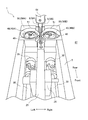
- FIG. 1 is a perspective view of a two-needle lockstitch sewing machine according to an embodiment of the present invention.
- FIG. 2 is a perspective view showing a state in which a cover and a feed dog near the distal end of the lower arm of the two-needle lockstitch sewing machine according to the embodiment of the present invention have been removed.
- FIG. 3 is a schematic diagram schematically illustrating a drive system of the two-needle lockstitch sewing machine according to the embodiment of the present invention.
- FIG. 4 is a plan view showing an arrangement of a loop catcher, a connecting shaft, and a lower shaft of the two-needle lockstitch sewing machine according to the embodiment of the present invention.
- FIG. 1 is a perspective view of a two-needle lockstitch sewing machine according to an embodiment of the present invention.
- FIG. 2 is a perspective view showing a state in which a cover and a feed dog near the distal end of the lower arm of the two-needle lockstitch sewing machine
- FIG. 5 is a left side view showing an arrangement of a loop catcher and a connection shaft of the two-needle lockstitch sewing machine according to the embodiment of the present invention.
- FIG. 6 is a plan view showing the arrangement of the hook receiving block of the two-needle lockstitch sewing machine according to the embodiment of the present invention.
- FIG. 7 is a rear view showing the arrangement of the hook receiving block of the two-needle lockstitch sewing machine according to the embodiment of the present invention.
- FIG. 8 is a perspective view showing the needle support of the two-needle lockstitch sewing machine according to the embodiment of the present invention and the vicinity thereof.
- FIG. 9 is a left side sectional view showing the needle support of the two-needle lockstitch sewing machine according to the embodiment of the present invention and the vicinity thereof.
- FIG. 10 is a front sectional view showing the needle support of the two-needle lockstitch sewing machine according to the embodiment of the present invention and the vicinity thereof.
- FIG. 11 is a plan view showing an arrangement of a hook receiving block of a two-needle lockstitch sewing machine according to another embodiment of the present invention.
- FIG. 12 is a rear view showing the arrangement of the hook receiving block of the two-needle lockstitch sewing machine according to another embodiment of the present invention.
- FIG. 13 is a plan view showing the arrangement of the hook receiving block of the two-needle lockstitch sewing machine according to another embodiment of the present invention.
- FIG. 14 is a rear view showing the arrangement of the hook receiving block of the two-needle lockstitch sewing machine according to another embodiment of the present invention.
- FIG. 1 is a perspective view of a two-needle lockstitch sewing machine 1 according to an embodiment of the present invention.
- the near side in the cloth feeding direction will be referred to as “front” and the far side will be referred to as “rear” as appropriate.
- “left” and “right” appropriately used in the description are directions based on a state in which the cloth feed direction is set.
- the two-needle lockstitch sewing machine 1 is a lockstitch sewing machine suitable for sewing a tubular material such as a sleeve of clothing. As shown in FIG. 1, the two-needle lockstitch sewing machine 1 includes a bed portion 2, a support portion 6 erected upward from the bed portion 2, and an upper arm portion 7 provided above the support portion 6. And a jaw 8 provided near the tip of the upper arm 7 and on which the needle 9 is disposed.
- the bed portion 2 is a portion installed on a sewing machine table (not shown) or the like to support the two-needle lockstitch sewing machine 1.
- the bed 2 extends in the cloth feed direction, that is, the front-back direction, and has a base 3 on which an upright column 6 is erected, and a bed formed continuously from the vicinity of the front end of the base 3 and extending leftward. It has a front part 4 and a lower arm part 5 extending from the vicinity of the left end of the bed front part 4 in the cloth feeding direction, that is, rearward.
- a recess 67 is formed between the base 3 and the lower arm 5 of the bed 2 so as to open rearward, whereby the bed 2 has a substantially concave shape in plan view.
- a column 6 is erected on the upper surface of the bed 2, more specifically, on the upper surface near the rear end of the base 3, a column 6 is erected.
- an upper arm portion 7 which is formed substantially continuously from the support portion 6 and extends in the left-right direction so as to be substantially horizontal and substantially orthogonal to the cloth feeding direction is formed.
- a main shaft 10 (see FIG. 3), described later, for driving the needle 9 is disposed inside the upper arm 7.
- a jaw 8 is formed extending continuously downward from the upper arm 7 and having a needle drive link mechanism 11 (see FIG. 3) disposed therein.
- a pair of needles 9 connected to a needle drive link mechanism 11 are disposed substantially vertically so as to be able to reciprocate up and down.
- the bed front part 4 of the bed part 2 is located forward of the upper arm part 7, and a lower shaft 20 (see FIG. 3) extending in the left-right direction is disposed inside the bed front part 4.
- the lower arm 5 extending rearward from the bed front 4 extends to below the jaw 8, and a connecting shaft 30 (see FIG. 3) extending in the front-rear direction is arranged inside the lower arm 5. Is established. The details of the lower shaft 20 and the connecting shaft 30 will be described later.
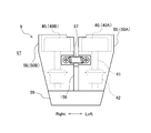
- FIG. 2 is a perspective view showing a state where the cover near the tip of the lower arm 5 of the two-needle lockstitch machine 1 and the feed dog 26 (see FIG. 4) are removed. As shown in FIG. 2, a pair of loop catchers 40 are disposed inside the vicinity of the distal end of the lower arm portion 5 so as to correspond to the pair of needles 9, respectively.
- the needles 9 are disposed at predetermined intervals in the left-right direction, and a left loop catcher 40A is provided on the left side of the left hand 9A, and a right loop catcher 40B is provided on the right side of the right hand 9B. Are arranged.
- the loop catcher 40 is disposed in a hook receiving hole 51 formed on the upper surface of a pair of left and right hook receiving blocks 50 provided near the distal end of the lower arm 5 and extends substantially vertically. It has a shaft 41 (see FIG. 5), and is configured to rotate around the hook shaft 41. As will be described in detail later, the loop catcher 40 rotates in conjunction with the vertical movement of the needle 9.
- the outer hook provided at the top of the loop catcher 40 is formed with a sword tip 43 (see FIG. 6) for catching the upper thread loop formed by the vertical movement of the needle 9.
- an inner shuttle that accommodates a bobbin 48 wound with a lower thread is disposed inside the outer shuttle of the loop catcher 40.
- the bed portion 2 of the two-needle lockstitch sewing machine 1 has a substantially concave shape in a plan view, and the bed portion 2 has a lower arm portion 5 extending rearward. Is formed. Then, as shown in FIG. 2, a loop catcher 40 is provided near the tip of the lower arm 5. With such a configuration, sewing of the tubular object is facilitated.
- the dough is rolled into a tubular shape so as to enclose the lower arm portion 5, and the opposing sides along the axial direction of the rolled dough are positioned on the lower arm on which the needle 9 and the loop catcher 40 are arranged. It can be sent near the tip of the part 5. This makes it possible to sew the opposing sides of the cylindrically rolled fabric and easily sew the cylindrical object.
- a tubular object such as a sleeve portion of clothing conventionally sewn by chain stitching can be easily formed by lockstitching.
- the tubular object formed by the main stitch has a small number of sewing threads exposed from the cloth and has a high sewing strength. That is, the two-needle lockstitch sewing machine 1 can sew a tough, soft-touch tubular stitch that is suitable for, for example, sleeves of portswear.
- FIG. 3 is a schematic view showing an outline of a drive system of the two-needle lockstitch sewing machine 1.
- the two-needle lockstitch sewing machine 1 has a main shaft 10 for moving the needle 9 up and down.
- the main shaft 10 is provided inside the upper arm portion 7 (see FIG. 1), and extends substantially horizontally in the left-right direction.
- the main shaft 10 is connected to a motor 15 via a timing belt 17 and pulleys 13 and 16, and is driven to rotate by the motor 15.
- the needle 9 is connected to the vicinity of the left end of the main shaft 10 via a needle drive link mechanism 11.
- a balance (not shown) is connected to the main shaft 10 via a link mechanism so as to reciprocate.
- the two-needle lockstitch sewing machine 1 has a lower shaft 20 and a connecting shaft 30 for rotating the loop catcher 40.
- the lower shaft 20 is connected to the main shaft 10 via a timing belt 18 and pulleys 12 and 21. Thereby, rotational power is transmitted from the main shaft 10 to the lower shaft 20, and the lower shaft 20 rotates in conjunction with the main shaft 10.
- connection shaft 30 is a rotary shaft that connects the shuttle shaft 41 of the loop catcher 40 and the lower shaft 20 so that power can be transmitted. As a result, the rotational power of the lower shaft 20 is transmitted to the shuttle shaft 41 via the connection shaft 30, and the loop catcher 40 rotates.
- the shuttle shaft 41 is a rotary shaft arranged substantially vertically as described above.
- the lower shaft 20 is provided with a cam 23 for driving a feed rod 25 provided with a feed dog 26 near the tip.
- the feed dog 26 is driven by the rotation of the lower shaft 20, and repeatedly moves in the cloth feed direction and the vertical direction along a predetermined trajectory.
- FIG. 4 is a plan view showing the arrangement of the loop catcher 40, the connecting shaft 30, and the lower shaft 20 of the two-needle lockstitch sewing machine 1.
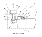
- FIG. 5 is a left side view showing the arrangement of the loop catcher 40 and the connecting shaft 30 of the two-needle lockstitch sewing machine 1.
- the lower shaft 20 is provided inside the bed front part 4, and is provided substantially parallel to the main shaft 10 (see FIG. 3). That is, the lower shaft 20 is substantially horizontal and extends in the left-right direction.
- the lower shaft 20 is rotatably supported by the bed 2 via bearings 24 such as a sliding bearing and a rolling bearing.
- the pair of connecting shafts 30 are disposed inside the lower arm 5, and extend in the cloth feeding direction, that is, in the front-rear direction, side by side and substantially parallel to each other. That is, the connection shaft 30 is provided so as to be substantially orthogonal to the lower shaft 20.
- the connecting shaft 30 is rotatably supported by the bed 2 via bearings 37 and 38 such as a sliding bearing and a rolling bearing.
- each connecting shaft 30 a gear 33 is provided, and the gear 33 meshes with the gear 22 provided near the left end of the lower shaft.
- a gear 34 is provided, and the gear 34 meshes with a gear 42 attached to the shuttle shaft 41, as shown in FIG.
- the connecting shaft 30 is connected to the lower shaft 20 and the shuttle shaft 41 via gears 22, 33, 34, and 42.
- the rotational power of the lower shaft 20 can be efficiently and accurately transmitted to the shuttle shaft 41, and the loop catcher 40 can be rotated with high accuracy, so that a suitable lockstitch can be formed.
- the gears 22, 33, 34, and 42 may be bevel gears or bevel gears. Bevel bevel gears are preferred.
- the shuttle shaft 41 of the loop catcher 40 is rotatably supported by a shuttle receiving block 50 via bearings 44 and 45 such as a sliding bearing and a rolling bearing.
- bearings 44 and 45 such as a sliding bearing and a rolling bearing.
- a thrust bearing 46 for rotatably moving the bottom of the outer hook of the loop catcher 40 is provided.
- the thrust bearing 46 for example, a needle bearing which is thin and has low rolling resistance is preferable.
- the thrust bearing 46 between the loop catcher 40 and the shuttle receiving block 50 By providing the thrust bearing 46 between the loop catcher 40 and the shuttle receiving block 50, the rotational resistance of the loop catcher 40 is reduced, and the downward acting on the shuttle shaft 41 by the engagement of the gear 34 and the gear 42.
- the loop catcher 40 can be suitably supported against the thrust force. Thereby, smooth and efficient rotation of the loop catcher 40 becomes possible.
- the lower shaft 20 for rotating the loop catcher 40 is located forward of the needle 9 and the loop catcher 40.
- the loop catcher 40 is rotationally driven via a connecting shaft 30 extending in the front-rear direction.
- a space for feeding the fabric can be secured left and right with respect to the vicinity of the needle 9 and the loop catcher 40 where the fabric is sewn. . That is, the lower shaft 20 is disposed at the front part 4 of the bed, and a space for passing the cloth behind the lower shaft 20 and below the main shaft 10, specifically, the recess 67 can be secured.
- the bed 2 can be easily sewn even if it is a relatively small-diameter cylindrical member such as a sleeve of a garment without being in the way.
- a feed dog 26 for feeding the fabric to be sutured rearward is arranged between the pair of loop catchers 40.
- the feed dog 26 is fixed between the pair of connecting shafts 30 near the rear end of the feed rod 25 extending in the front-rear direction.
- the feed rod 25 is supported by the support portion 28 so as to be slidable in the front-rear direction and swingable in the vertical direction, and is driven by the cam 23 fixed to the lower shaft 20 as described above.
- a pair of the cams 23 is provided near the left end of the lower shaft 20, and is disposed outside the gears 22 in the left-right direction so as to sandwich the pair of gears 22. That is, one cam 23A is provided on the left side of the left gear 22A for driving the left connecting shaft 30A, and the other cam 23B is provided on the right side of the right gear 22B for driving the right connecting shaft 30B. Have been.
- the front side of the feed rod 25 is divided into a left connecting portion 25a connected to the left cam 23A and a right connecting portion 25b connected to the right cam 23B.
- the right connecting portion 25b is formed continuously and integrally with the feed rod 25, and the left connecting portion 25a is connected to the feed rod 25 via a pin 27 so as to be position-adjustable.
- the mechanism for driving the feed dog 26 is configured as described above, the distance between the pair of connecting shafts 30 is reduced while avoiding contact between the feed rod 25 and the like and the gear 22 and the like. Can be reduced in the left-right direction. Thereby, the shape of the lower arm 5 suitable for sewing a relatively small-diameter cylindrical object such as a sleeve of clothing is realized.
- connection shaft 30 is connected to a drive shaft 31 connected to the lower shaft 20 via gears 22 and 33 and to a shuttle shaft 41 via gears 34 and 42.
- driven shaft portion 32 may be connected by a joint portion 35.
- the joint 35 is a shaft joint that can change the relative angle of the drive shaft 31 and the driven shaft 32.
- a universal joint such as a hook-type universal joint or a ball-shaped universal joint is desirable. Thereby, even if the arrangement interval of the pair of loop catchers 40 is changed, the rotational relative angle between the drive shaft portion 31 and the driven shaft portion 32 is changed, and the rotational power is accurately transferred from the lower shaft 20 to the shuttle shaft 41. It can be transmitted efficiently.
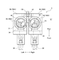
- FIG. 6 is a plan view showing the hook receiving block 50 of the two-needle lockstitch sewing machine 1
- FIG. 7 is a rear view showing the hook receiving block 50.
- the pair of shuttle receiving blocks 50 in which the loop catchers 40 are respectively arranged are supported by pins 53 so as to be swingable in the horizontal direction so that the arrangement interval of the loop catchers 40 can be adjusted. I have.
- the pin 53 is fixed to the base 59 of the lower arm 5 shown in FIG. 7, and is arranged at a position corresponding to the joint 35 of the connecting shaft 30 as shown in FIG. Accordingly, when the arrangement of the shuttle receiving block 50 is changed by rotating the shuttle receiving block 50 in the horizontal direction about the pin 53, the joint relative angle between the drive shaft 31 and the driven shaft 32 by the joint portion 35. Is changed, and the rotational power can be transmitted efficiently.
- both the left hook receiving block 50A and the right hook receiving block 50B are configured to be movable. However, at least one of the pair of hook blocks 50 moves in the horizontal direction. What is necessary is just to be comprised freely. If only one kamaishi block 50 is movable, the arrangement interval of the loop catcher 40 can be adjusted.
- the pair of shuttle receiving blocks 50 are provided with an urging means 57 for urging the pair of hook receiving blocks 50 in a direction to reduce the mutual arrangement interval.
- the urging means 57 is, for example, an elastic body such as a tension coil spring or rubber.
- urging is performed to press the hook receiving block 50 from outside in the left-right direction of the hook receiving block 50 so as to reduce the arrangement interval of the hook receiving block 50, for example, a compression coil spring or other various types. It may be an elastic body.
- a spacer 56 is inserted between the pair of shuttle receiving blocks 50 and serves as adjusting means for increasing the arrangement interval of the shuttle receiving block 50. And an adjustment screw 55 for pushing the screw.
- the spacer 56 is formed so as to gradually increase in width from the front end side to the rear end side inserted into the shuttle receiving block 50, for example, a substantially wedge shape, a substantially pyramid shape, a substantially truncated pyramid shape, and a substantially cone shape. Or a member having a substantially frustoconical shape or the like.
- the adjustment screw 55 is screwed into a screw hole of a support member 58 attached to the base 59, and is screwed forward between the shuttle receiving blocks 50 to press the spacer 56.
- the adjusting screw 55 is screwed in, the spacer 56 is pushed forward and moved so as to be inserted between the hook receiving blocks 50, and the arrangement interval of the pair of loop catchers 40 can be easily widened.
- the arrangement interval of the loop catcher 40 can be easily adjusted, and thereby a suitable lockstitch seam can be formed.
- the urging means 57, the adjusting screw 55, and the spacer 56 are configured to be attached to the rear side of the shuttle receiving block 50. It may be provided in another portion such as the front side of the block 50.
- the adjusting screw 55 is provided on the rear side of the shuttle receiving block 50 as described above, the head of the adjusting screw 55 is exposed from the back surface of the lower arm 5, so that the sewing operation is not hindered and the loop is not hindered. This is excellent in that the operation of adjusting the arrangement interval of the catchers 40 is easy.
- FIG. 8 to 10 are views showing the needle support 61 of the two-needle lockstitch sewing machine 1 and the vicinity thereof, FIG. 8 is a perspective view, and FIG. FIG. 10 is a front cross-sectional view at the center of the needle support 61.
- the pair of needles 9 are attached via a needle support 61 near the lower end of a needle bar 60 connected to the needle drive link mechanism 11 (see FIG. 3).
- the lower end of the needle bar 60 is fitted or screwed into a mounting hole 61 a formed in the upper portion of the needle support 61, and the needle support is The tool 61 is attached.
- the needle support 61 is fixed to the needle bar 60 by the set screw 63.
- a mounting groove 61b that opens downward and in the left-right direction is formed in a lower portion of the needle support 61, and a needle fixing tool 62 to which the needle 9 is fixed is mounted in the mounting groove 61b.
- the needle fixture 62 is inserted into the mounting groove 61b so as to slide from one of the left and right. Then, as shown in FIG. 9, the needle fixing tool 62 fitted in the needle supporting tool 61 is fixed by a set screw 64.
- a needle mounting hole 62a is formed at a lower portion of the needle fixing tool 62 at a predetermined interval and substantially in parallel.
- the upper ends of the pair of needles 9 are inserted into the needle mounting hole 62a.
- the needle 9 is fixed to the needle fixing tool 62 by the set screw 65.
- the needle 9 may be fixed to the needle fixing tool 62 before the needle fixing tool 62 is attached to the needle support tool 61.
- the width L1 which is the longitudinal dimension of the upper part of the mounting groove 61b and the needle fixture 62 inserted therein, is larger than the width L2, which is the longitudinal dimension of the lower part of the mounting groove 61b. Accordingly, it is possible to prevent the needle fixing tool 62 inserted into the mounting groove 61b of the needle supporting tool 61 by sliding horizontally from the left or right from dropping off from the needle supporting tool 61. Thereby, the work of attaching the needle fixing tool 62 to the needle support tool 61 becomes easy. With the above configuration, the pair of needles 9 can be easily attached to the correct position at the lower end of the needle bar 60.
- FIG. 11 is a plan view showing the hook receiving block 50 of the two-needle lockstitch sewing machine 1
- FIG. 12 is a rear view showing the hook receiving block 50.
- a spacer 156 having a substantially plate shape may be provided as an adjusting means for adjusting the arrangement interval between the pair of shuttle receiving blocks 50.
- the spacer 156 is a member having a substantially plate shape, and one main surface thereof abuts the left hook receiving block 50A and the other main surface thereof abuts the right hook receiving block 50B. Is inserted between the pair of shuttle receiving blocks 50.
- the spacer 156 may have a substantially plate-like configuration having one main surface contacting the left hook receiving block 50A and the other main surface contacting the right hook receiving block 50B. May be a hollow cassette or the like.
- the arrangement interval of the pair of shuttle receiving blocks 50 is increased according to the thickness dimension of the spacer 156. Then, the arrangement interval of the pair of loop catchers 40 is widened.
- the spacer 156 is formed with a predetermined thickness so that the arrangement interval of the loop catchers 40 becomes a suitable value suitable for the target lockstitch. That is, a plurality of types of spacers 156 having different thickness dimensions are prepared in accordance with the intended main stitches. Therefore, by replacing the spacer 156 in accordance with the lock stitch to be formed, the arrangement interval between the pair of loop catchers 40 can be easily and accurately adjusted to a suitable state.
- the spacer 156 or the shuttle receiving block 50 may be provided with a support or the like for fixing the spacer 156 inserted between the pair of shuttle receiving blocks 50 at a predetermined position. Accordingly, the work of attaching and detaching the spacer 156 is facilitated, and the spacer 156 can be held at an appropriate position.
- FIG. 13 is a plan view showing a hook receiving block 50 of another embodiment in which an adjusting means for increasing the arrangement interval of the hook receiving block 50 is changed
- FIG. 14 is a rear view showing the hook receiving block 50.
- the pair of shuttle receiving blocks 50 are provided with an adjusting screw 255 as adjusting means for adjusting the arrangement interval between them.
- the adjusting screw 255 has screw portions 256 on both ends of the screw shaft, and is disposed on the pair of shuttle receiving blocks 50 so as to extend in the left-right direction.
- the pair of hook receiving blocks 50 is formed with a female screw portion 258 into which the screw portion 256 of the adjusting screw 255 is screwed.
- the screw portion 256A at one end of the adjusting screw 255 and the screw portion 256B at the other end are formed in reverse screw shapes.
- the screw hole of the female screw portion 258A provided on the left hook receiving block 50A and the screw hole of the female screw portion 258B provided on the right hook receiving block 50B correspond to the screw portion 256 of the adjusting screw 255. , Formed in a reverse screw shape.
- the screw hole of the female screw part 258A provided on the left hook receiving block 50A and the screw part 256A on one end side of the adjusting screw 255 screwed therein are formed in a left-handed screw shape.
- the screw hole of the female screw portion 258B provided on the right hook receiving block 50B and the screw portion 256B on the other end side of the adjusting screw 255 screwed therein are formed in a right-handed screw shape.
- the arrangement interval of the pair of shuttle receiving blocks 50 can be easily adjusted by rotating the adjusting screws 255. Can be adjusted.
- the threaded portions 256 at both ends are screwed into the threaded holes of the left and right internal threaded portions 258 to reduce the arrangement interval between the pair of shuttle receiving blocks 50. Can be narrowed.
- the arrangement interval of the pair of shuttle receiving blocks 50 can be increased. Therefore, the arrangement interval between the pair of loop catchers 40 can be easily widened. As described above, according to the two-needle lockstitch sewing machine 1 having the above configuration, the arrangement interval of the loop catcher 40 can be easily adjusted.
Landscapes
- Engineering & Computer Science (AREA)
- Textile Engineering (AREA)
- Sewing Machines And Sewing (AREA)
Abstract
Description
この種の環縫ミシンのベッド部には、上腕部と略直交するよう布送り方向に延出される下腕部が形成されている。下腕部は、針が配置される顎部の下方まで延在し、下腕部の先端近傍には、針に対応して配置される針案内部材や糸を捕捉するルーパ、布を送るための送り歯等が設けられる。
図1は、本発明の実施形態に係る2本針本縫ミシン1の透視図である。なお、以下の説明では、適宜、布送り方向の手前側を「前」、奥側を「後」と称する。また、説明で適宜用いる「左」及び「右」とは、布送り方向を向いた状態を基準とする方向である。
上記の構成により、一対の針9を針棒60の下端の正確な位置に容易に取り付けることができる。
図13及び図14に示すように、一対の釜受ブロック50には、互いの配置間隔を調整する調整手段として、調整ねじ255が設けられている。調整ねじ255は、ねじ軸の両端部側にねじ部256を有し、左右方向に延在するよう一対の釜受ブロック50に配設されている。
このように、上記構成を有する2本針本縫ミシン1によれば、ループ捕捉器40の配置間隔を容易に調整することができる。
2 ベッド部
3 基部
4 ベッド前部
5 下腕部
6 支柱部
7 上腕部
8 顎部
9 針
10 主軸
15 モータ
20 下軸
22 歯車
23 カム
25 送り棒
25a 左連接部
25b 右連接部
26 送り歯
30 連結軸
31 駆動軸部
32 従動軸部
33 歯車
34 歯車
35 継手部
40 ループ捕捉器
41 釜軸
42 歯車
50 釜受ブロック
55 調整ねじ
56 スペーサ
57 付勢手段
156 スペーサ
255 調整ねじ
256 ねじ部
258 雌ねじ部
Claims (5)
- 布送り方向に対して左右方向に所定の間隔を設けて配置されて上下方向に往復移動する一対の針と、
一対の前記針にそれぞれ対応して配置されて、上下方向に延在する釜軸を中心に回転して前記針によって形成される上糸のループを捕捉する一対のループ捕捉器と、
前記針及び前記ループ捕捉器よりも布送り方向の手前に配置されて左右方向に延在し、前記針を駆動する主軸に連動して回転する下軸と、
布送り方向に延在して前記下軸及び前記釜軸に対して動力伝達可能に連結されて回転する連結軸と、を有し、
前記ループ捕捉器は、前記下軸の回転動力が前記連結軸を介して前記釜軸に伝達されることにより前記針の上下動に連動して回転駆動されることを特徴とする2本針本縫ミシン。 - 内部に前記下軸が配設されたベッド部と、
前記ベッド部から上方に向かって立設された支柱部と、
前記支柱部の上部に設けられて左右方向に延在し内部に前記主軸が配設された上腕部と、
前記上腕部の先端近傍に設けられて前記針が配置された顎部と、を有し、
前記ベッド部には、前記下軸が配設されたベッド前部から布送り方向に延設されて前記顎部の下方に達する下腕部が形成され、
前記下腕部の内部に前記連結軸が配設され、前記下腕部の先端近傍に前記ループ捕捉器が配設されたことを特徴とする請求項1に記載の2本針本縫ミシン。 - 前記連結軸は、歯車を介して前記下軸及び前記釜軸に連結されていることを特徴とする請求項1または請求項2に記載の2本針本縫ミシン。
- 前記連結軸は、前記下軸に連結された駆動軸部と、前記釜軸に連結された従動軸部と、前記駆動軸部と前記従動軸部を軸相対角度可変に連結する継手部と、を有することを特徴とする請求項1ないし請求項3の何れか1項に記載の2本針本縫ミシン。
- 前記ループ捕捉器がそれぞれ配置されて少なくとも一方が移動自在に構成された一対の釜受ブロックと、
一対の前記釜受ブロックの配置間隔を狭める方向に付勢する付勢手段と、
一対の前記釜受ブロックの配置間隔を調整する調整手段と、を有し、
一対の前記ループ捕捉器は、配置間隔が変更自在であることを特徴とする請求項1ないし請求項4の何れか1項に記載の2本針本縫ミシン。
Priority Applications (6)
| Application Number | Priority Date | Filing Date | Title |
|---|---|---|---|
| JP2020525199A JP7138360B2 (ja) | 2018-06-22 | 2018-06-22 | 2本針本縫ミシン |
| CN201880092465.0A CN111989431A (zh) | 2018-06-22 | 2018-06-22 | 双针平缝机 |
| KR1020207031212A KR102452185B1 (ko) | 2018-06-22 | 2018-06-22 | 2본침 로크 스티치 재봉틀 |
| US17/048,812 US11326284B2 (en) | 2018-06-22 | 2018-06-22 | Double-needle lockstitch sewing machine |
| EP18923353.9A EP3812496A4 (en) | 2018-06-22 | 2018-06-22 | DOUBLE NEEDLE LOCKSTITCH SEWING MACHINE |
| PCT/JP2018/023816 WO2019244342A1 (ja) | 2018-06-22 | 2018-06-22 | 2本針本縫ミシン |
Applications Claiming Priority (1)
| Application Number | Priority Date | Filing Date | Title |
|---|---|---|---|
| PCT/JP2018/023816 WO2019244342A1 (ja) | 2018-06-22 | 2018-06-22 | 2本針本縫ミシン |
Publications (1)
| Publication Number | Publication Date |
|---|---|
| WO2019244342A1 true WO2019244342A1 (ja) | 2019-12-26 |
Family
ID=68982822
Family Applications (1)
| Application Number | Title | Priority Date | Filing Date |
|---|---|---|---|
| PCT/JP2018/023816 WO2019244342A1 (ja) | 2018-06-22 | 2018-06-22 | 2本針本縫ミシン |
Country Status (6)
| Country | Link |
|---|---|
| US (1) | US11326284B2 (ja) |
| EP (1) | EP3812496A4 (ja) |
| JP (1) | JP7138360B2 (ja) |
| KR (1) | KR102452185B1 (ja) |
| CN (1) | CN111989431A (ja) |
| WO (1) | WO2019244342A1 (ja) |
Cited By (2)
| Publication number | Priority date | Publication date | Assignee | Title |
|---|---|---|---|---|
| CN113373600A (zh) * | 2020-03-09 | 2021-09-10 | 启翔股份有限公司 | 可变针距的双针缝制方法 |
| CN114737323A (zh) * | 2022-04-07 | 2022-07-12 | 武汉市依翎针织有限责任公司 | 一种针织服装生产用智能平缝机 |
Families Citing this family (2)
| Publication number | Priority date | Publication date | Assignee | Title |
|---|---|---|---|---|
| KR20220112918A (ko) | 2021-02-05 | 2022-08-12 | 석정호 | 복수의 바늘을 구비하는 재봉기 |
| CN115142206A (zh) * | 2021-03-31 | 2022-10-04 | 本田技研工业株式会社 | 缝制装置 |
Citations (7)
| Publication number | Priority date | Publication date | Assignee | Title |
|---|---|---|---|---|
| US3875877A (en) * | 1974-03-13 | 1975-04-08 | Singer Co | Feed-off-the-arm sewing machine |
| JPS60185584A (ja) | 1984-03-02 | 1985-09-21 | ブラザー工業株式会社 | 2本針本縫ミシン |
| JPH0424084A (ja) | 1990-05-21 | 1992-01-28 | Brother Ind Ltd | 二重環縫腕ミシンの針案内装置 |
| JPH06134166A (ja) * | 1992-10-22 | 1994-05-17 | Hirose Mfg Co Ltd | 本縫ミシン |
| JPH11235492A (ja) * | 1998-02-20 | 1999-08-31 | Juki Corp | 筒型ミシン |
| JP2003111991A (ja) | 2001-10-05 | 2003-04-15 | Juki Corp | 本縫い2本針ミシンの釜装置 |
| JP2010115359A (ja) * | 2008-11-13 | 2010-05-27 | Brother Ind Ltd | ミシンの釜駆動機構 |
Family Cites Families (17)
| Publication number | Priority date | Publication date | Assignee | Title |
|---|---|---|---|---|
| US1150123A (en) | 1914-05-21 | 1915-08-17 | United Shoe Machinery Ab | Lock-stitch sewing-machine. |
| US1917756A (en) * | 1929-11-23 | 1933-07-11 | Singer Mfg Co | Feed-off-arm sewing machine |
| US2367813A (en) * | 1944-02-18 | 1945-01-23 | Singer Mfg Co | Work-supporting post for sewing machines |
| US3911841A (en) | 1974-07-24 | 1975-10-14 | Singer Co | Looptaker drive for a sewing machine |
| US4043283A (en) * | 1975-07-17 | 1977-08-23 | Amf Incorporated | Sewing apparatus employing twin needles |
| US4989527A (en) * | 1986-09-19 | 1991-02-05 | Automated Machinery Systems, Inc. | Sewing system |
| JPH0424804A (ja) * | 1990-05-20 | 1992-01-28 | Fujitsu Ltd | ロボット制御装置 |
| US6305304B1 (en) * | 1997-11-25 | 2001-10-23 | Juki Corporation | Two-needle sewing machine |
| JP4198236B2 (ja) | 1998-08-18 | 2008-12-17 | Juki株式会社 | 2本針ミシンおよびベルトループ縫付けミシン |
| CN2444971Y (zh) * | 2000-08-30 | 2001-08-29 | 朱逢权 | 一种筒状物专用缝纫机 |
| JP2004147713A (ja) * | 2002-10-29 | 2004-05-27 | Mikasa:Kk | ミシン |
| JP5253980B2 (ja) | 2008-11-25 | 2013-07-31 | Juki株式会社 | 下糸張力制御装置 |
| CN201354413Y (zh) | 2009-01-14 | 2009-12-02 | 朱强 | 一种高台缝纫机的摆梭结构 |
| CN202227103U (zh) * | 2011-09-15 | 2012-05-23 | 张金福 | 一种三针锁式线迹平缝机的传动机构 |
| JP6134166B2 (ja) | 2013-03-12 | 2017-05-24 | 株式会社Screenホールディングス | 位置検出装置および位置検出方法 |
| CN105220373B (zh) | 2014-06-25 | 2019-06-28 | 飞马缝纫机制造株式会社 | 送出臂型缝纫机 |
| CN104911837A (zh) | 2015-06-19 | 2015-09-16 | 台州学院 | 一种三针锁式线迹平缝机的传动机构 |
-
2018
- 2018-06-22 WO PCT/JP2018/023816 patent/WO2019244342A1/ja active Application Filing
- 2018-06-22 CN CN201880092465.0A patent/CN111989431A/zh active Pending
- 2018-06-22 JP JP2020525199A patent/JP7138360B2/ja active Active
- 2018-06-22 KR KR1020207031212A patent/KR102452185B1/ko active IP Right Grant
- 2018-06-22 EP EP18923353.9A patent/EP3812496A4/en not_active Withdrawn
- 2018-06-22 US US17/048,812 patent/US11326284B2/en active Active
Patent Citations (7)
| Publication number | Priority date | Publication date | Assignee | Title |
|---|---|---|---|---|
| US3875877A (en) * | 1974-03-13 | 1975-04-08 | Singer Co | Feed-off-the-arm sewing machine |
| JPS60185584A (ja) | 1984-03-02 | 1985-09-21 | ブラザー工業株式会社 | 2本針本縫ミシン |
| JPH0424084A (ja) | 1990-05-21 | 1992-01-28 | Brother Ind Ltd | 二重環縫腕ミシンの針案内装置 |
| JPH06134166A (ja) * | 1992-10-22 | 1994-05-17 | Hirose Mfg Co Ltd | 本縫ミシン |
| JPH11235492A (ja) * | 1998-02-20 | 1999-08-31 | Juki Corp | 筒型ミシン |
| JP2003111991A (ja) | 2001-10-05 | 2003-04-15 | Juki Corp | 本縫い2本針ミシンの釜装置 |
| JP2010115359A (ja) * | 2008-11-13 | 2010-05-27 | Brother Ind Ltd | ミシンの釜駆動機構 |
Non-Patent Citations (1)
| Title |
|---|
| See also references of EP3812496A4 |
Cited By (4)
| Publication number | Priority date | Publication date | Assignee | Title |
|---|---|---|---|---|
| CN113373600A (zh) * | 2020-03-09 | 2021-09-10 | 启翔股份有限公司 | 可变针距的双针缝制方法 |
| CN113373600B (zh) * | 2020-03-09 | 2022-07-22 | 启翔股份有限公司 | 可变针距的双针缝制方法 |
| CN114737323A (zh) * | 2022-04-07 | 2022-07-12 | 武汉市依翎针织有限责任公司 | 一种针织服装生产用智能平缝机 |
| CN114737323B (zh) * | 2022-04-07 | 2023-06-23 | 武汉市依翎针织有限责任公司 | 一种针织服装生产用智能平缝机 |
Also Published As
| Publication number | Publication date |
|---|---|
| EP3812496A1 (en) | 2021-04-28 |
| JPWO2019244342A1 (ja) | 2021-07-08 |
| KR20200138341A (ko) | 2020-12-09 |
| US11326284B2 (en) | 2022-05-10 |
| CN111989431A (zh) | 2020-11-24 |
| US20210164141A1 (en) | 2021-06-03 |
| JP7138360B2 (ja) | 2022-09-16 |
| EP3812496A4 (en) | 2022-01-12 |
| KR102452185B1 (ko) | 2022-10-11 |
Similar Documents
| Publication | Publication Date | Title |
|---|---|---|
| WO2019244342A1 (ja) | 2本針本縫ミシン | |
| JP6502699B2 (ja) | ミシン | |
| JP4725864B2 (ja) | 偏平縫いミシン | |
| CN103194860B (zh) | 纽扣孔锁边缝纫机 | |
| JP6045318B2 (ja) | ミシン | |
| JP2006314423A (ja) | ミシンのスプレッダー機構 | |
| JP6537056B2 (ja) | 2本針本縫ミシン | |
| US5653187A (en) | Upper feed mechanism for sewing machine and sewing machine having the same | |
| JP6374661B2 (ja) | ミシン | |
| JP2007296253A (ja) | ミシン | |
| US773653A (en) | Embroidering-machine. | |
| JP2007296254A (ja) | ミシン | |
| CN210287758U (zh) | 一种缝纫机的针杆摆动装置 | |
| KR20090076821A (ko) | 단추구멍박기 재봉기 | |
| US7600481B2 (en) | Upper looper driving device of sewing machine | |
| US1283477A (en) | Ornamental-stitch sewing-machine. | |
| US1300532A (en) | Overstitch sewing-machine. | |
| KR100648477B1 (ko) | 미싱의 바늘받이 장치 | |
| US1355242A (en) | Feeding mechanism for sewing-machines | |
| JP2023092035A (ja) | ミシン | |
| US166805A (en) | Improvement in machines for sewing hosiery-seams | |
| US1370473A (en) | Button-sewing machine | |
| US419403A (en) | Needle clamping and looping device for sewing-machines | |
| JPH0424046A (ja) | 単環縫いボタン付けミシン | |
| US179709A (en) | Improvement in sewing-machines for embroidering |
Legal Events
| Date | Code | Title | Description |
|---|---|---|---|
| 121 | Ep: the epo has been informed by wipo that ep was designated in this application |
Ref document number: 18923353 Country of ref document: EP Kind code of ref document: A1 |
|
| ENP | Entry into the national phase |
Ref document number: 2020525199 Country of ref document: JP Kind code of ref document: A |
|
| ENP | Entry into the national phase |
Ref document number: 20207031212 Country of ref document: KR Kind code of ref document: A |
|
| NENP | Non-entry into the national phase |
Ref country code: DE |
|
| WWE | Wipo information: entry into national phase |
Ref document number: 2018923353 Country of ref document: EP |