WO2019225211A1 - 回転電機の積層コアおよび回転電機 - Google Patents
回転電機の積層コアおよび回転電機 Download PDFInfo
- Publication number
- WO2019225211A1 WO2019225211A1 PCT/JP2019/016164 JP2019016164W WO2019225211A1 WO 2019225211 A1 WO2019225211 A1 WO 2019225211A1 JP 2019016164 W JP2019016164 W JP 2019016164W WO 2019225211 A1 WO2019225211 A1 WO 2019225211A1
- Authority
- WO
- WIPO (PCT)
- Prior art keywords
- core
- laminated
- core member
- core piece
- piece
- Prior art date
- Legal status (The legal status is an assumption and is not a legal conclusion. Google has not performed a legal analysis and makes no representation as to the accuracy of the status listed.)
- Ceased
Links
Images








Classifications
-
- H—ELECTRICITY
- H02—GENERATION; CONVERSION OR DISTRIBUTION OF ELECTRIC POWER
- H02K—DYNAMO-ELECTRIC MACHINES
- H02K1/00—Details of the magnetic circuit
- H02K1/06—Details of the magnetic circuit characterised by the shape, form or construction
- H02K1/12—Stationary parts of the magnetic circuit
- H02K1/14—Stator cores with salient poles
- H02K1/146—Stator cores with salient poles consisting of a generally annular yoke with salient poles
- H02K1/148—Sectional cores
-
- H—ELECTRICITY
- H02—GENERATION; CONVERSION OR DISTRIBUTION OF ELECTRIC POWER
- H02K—DYNAMO-ELECTRIC MACHINES
- H02K15/00—Processes or apparatus specially adapted for manufacturing, assembling, maintaining or repairing of dynamo-electric machines
- H02K15/02—Processes or apparatus specially adapted for manufacturing, assembling, maintaining or repairing of dynamo-electric machines of stator or rotor bodies
- H02K15/021—Magnetic cores
- H02K15/022—Magnetic cores with salient poles
-
- H—ELECTRICITY
- H02—GENERATION; CONVERSION OR DISTRIBUTION OF ELECTRIC POWER
- H02K—DYNAMO-ELECTRIC MACHINES
- H02K3/00—Details of windings
- H02K3/46—Fastening of windings on the stator or rotor structure
- H02K3/52—Fastening salient pole windings or connections thereto
- H02K3/521—Fastening salient pole windings or connections thereto applicable to stators only
- H02K3/522—Fastening salient pole windings or connections thereto applicable to stators only for generally annular cores with salient poles
-
- H—ELECTRICITY
- H02—GENERATION; CONVERSION OR DISTRIBUTION OF ELECTRIC POWER
- H02K—DYNAMO-ELECTRIC MACHINES
- H02K2201/00—Specific aspects not provided for in the other groups of this subclass relating to the magnetic circuits
- H02K2201/09—Magnetic cores comprising laminations characterised by being fastened by caulking
-
- H—ELECTRICITY
- H02—GENERATION; CONVERSION OR DISTRIBUTION OF ELECTRIC POWER
- H02K—DYNAMO-ELECTRIC MACHINES
- H02K2213/00—Specific aspects, not otherwise provided for and not covered by codes H02K2201/00 - H02K2211/00
- H02K2213/03—Machines characterised by numerical values, ranges, mathematical expressions or similar information
Definitions
- This application relates to a laminated core of a rotating electrical machine and a rotating electrical machine including the laminated core.
- the ends of a plurality of core pieces are connected to each other to form an annular shape, and the core piece is formed by protruding magnetic teeth in a direction substantially perpendicular to the connecting direction,
- a connecting portion is formed on one end side of the end portion, and the first end surface on the one end side is formed in an arc shape centering on the connecting portion, and the first end portion is adjacent to the other end side.
- a second end face that can be fitted to the end face of the first core member, the first core member formed by arranging the core pieces in a strip shape through the both end faces, and the core piece being the first core member.
- the second core members which are alternately arranged in a strip shape in the connection direction, are stacked so that adjacent ends overlap each other in the stacking direction of the core pieces, and the connection portions are connected rotatably.
- the first end surface on one end side is formed in an arc shape centering on the connecting portion, and the first end of the adjacent one is on the other end side.
- a second end face that can be fitted to the end face is formed.
- the present application discloses a technique for solving the above-described problem, and an object thereof is to provide a laminated core and a rotating electrical machine of a rotating electrical machine having high roundness and high rigidity against an external force.
- a laminated core of a rotating electrical machine disclosed in the present application includes a back yoke having a convex end portion having a connecting portion at one end in the first circumferential direction and a concave end portion at the other end in the second circumferential direction; A plurality of first core pieces having magnetic teeth protruding radially inward from the yoke are arranged, and a convex end of the first core piece is fitted to a concave end of the first core piece.
- a formed first core member A back yoke having a convex end portion having a connecting portion at one end in the second circumferential direction and a concave end portion at the other end in the first circumferential direction, and a magnetic pole tooth projecting radially inward from the back yoke
- a second core member formed by fitting a plurality of second core pieces having a convex shape end portion of the second core piece and a concave end portion of the adjacent second core piece. The member including the first core member and the member including the second core member overlap the convex end portion of the first core piece and the convex end portion of the second core piece in the axial direction.
- a laminated core of rotating electrical machines laminated together by a connecting part so as to be rotatable When the laminated core is formed in an annular shape, the diameter of the contact surface formed by the convex end portion of the first core piece and the concave end portion of the first core piece adjacent in the circumferential direction.
- the part to be located is located in a plane including the central axis of the annular laminated core.
- the rotating electrical machine disclosed in the present application includes a laminated core of the rotating electrical machine configured in an annular shape, a winding wound around the magnetic pole teeth of the laminated core of the rotating electrical machine, and a radial direction of the laminated core of the rotating electrical machine It is provided with a rotor arranged inside.
- the laminated core and the rotating electrical machine of the rotating electrical machine disclosed in the present application it is possible to provide the laminated core and the rotating electrical machine of the rotating electrical machine having high roundness and high rigidity against the external force.
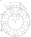
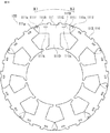
- FIG. 3 is a front view showing the configuration of the laminated core of the rotating electrical machine according to the first embodiment.
- FIG. 3 is a front view showing the configuration of the laminated core of the rotating electrical machine according to the first embodiment.
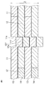
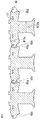
- 3 is a partial cross-sectional view illustrating a configuration of a connecting portion between core members according to Embodiment 1.
- FIG. It is a top view which shows a part of structure which has arrange
- FIG. 1 is a front view showing a configuration of a rotating electrical machine according to Embodiment 1.
- FIG. 6 is a front view showing a configuration of a laminated core of a rotating electrical machine according to Embodiment 2.
- FIG. 6 is a front view showing a configuration of a laminated core of a rotating electrical machine according to Embodiment 2.
- FIG. 6 is a partial cross-sectional view illustrating a configuration of a connecting portion between core members according to Embodiment 2.
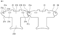
- FIG. It is a top view which shows a part of structure which has arrange
- FIG. 6 is a front view showing a configuration of a laminated core of a rotating electrical machine according to Embodiment 3.
- FIG. It is a top view which shows a part of structure which has arrange
- FIG. It is a perspective view which shows a mode that an insulator is attached to the core piece of the laminated core of the rotary electric machine by Embodiment 3.
- FIG. It is a front view which shows the structure of the laminated core of the rotary electric machine by the reference technique of this application. It is a front view which shows the structure of the laminated core of the rotary electric machine by the reference technique of this application. It is a partial cross section figure which shows the structure of the connection part of the core members by the reference technique of this application. It is a partial detail drawing for demonstrating the malfunction of the laminated core of the rotary electric machine by the reference technique of this application. It is a partial detail drawing for demonstrating the malfunction of the laminated core of the rotary electric machine by the reference technique of this application. It is a partial detail drawing for demonstrating the malfunction of the laminated core of the rotary electric machine by the reference technique of this application. FIG.
- FIG. 10 is a front view showing a configuration of a laminated core of a rotating electrical machine according to a fourth embodiment. It is a top view which shows a part of structure which has arrange
- the circumferential direction X, the radial direction Y, and the axial direction Z mean the circumferential direction X, the radial direction Y, and the axial direction Z, respectively, based on the rotating electrical machine.
- FIG. 19 and 20 are front views showing the structure of the laminated core of the rotating electrical machine according to the reference technique of the present application
- FIG. 21 is a partial cross-sectional view showing the structure of the connecting portion of the core members according to the reference technique of the present application
- FIG. 23 is a partial detail view for explaining a defect of the laminated core of the rotating electrical machine according to the reference technique of the present application.
- the core member is a generic name for the first core member and the second core member described below.
- the first core member 113 has a plurality of first core pieces 111 arranged annularly by fitting the first end 111A and the second end 111B of the first core pieces 111 adjacent in the circumferential direction. It is a thing.
- the first core piece 111 is made of a magnetic plate such as an electromagnetic steel plate, and has a first end 111A that is convex in the first circumferential direction X1 and a second end 111B that is concave in the second circumferential direction X2.
- a back yoke 111C having connecting portions 111e and 111f at one end 111A, and a magnetic pole tooth 111D protruding radially inward from the back yoke 111C.
- the second core member 114 has a plurality of second core pieces 112 annularly formed by fitting the first end 112 ⁇ / b> A and the second end 112 ⁇ / b> B of the second core pieces 112 adjacent in the circumferential direction.
- the first core member 113 shown in FIG. 19 and the circumferential direction are opposite to each other.
- the second core piece 112 is made of a magnetic plate such as an electromagnetic steel plate, and has a first end 112A having a convex shape in the second circumferential direction X2 and a second end 112B having a concave shape in the first circumferential direction X1.
- a back yoke 112C having connecting portions 112e and 112f at one end 112A, and a magnetic pole tooth 112D protruding radially inward from the back yoke 112C.
- the laminated core 120 of the rotating electrical machine is formed by alternately laminating the first core member 113 and the second core member 114 in the axial direction Z.
- the connecting portions 111e and 111f of the first core member 113 are composed of a concave portion 111e formed on the front surface and a convex portion 111f formed on the back surface.
- the connecting portions 112e and 112f of the second core member 114 are composed of a concave portion 112e formed on the front surface and a convex portion 112f formed on the back surface.
- the convex portion 111f that is the connecting portion of the first core member 113 is fitted into the concave portion 112e that is the connecting portion of the second core member 14
- the convex portion 112 f that is the connecting portion of the second core member 114 is fitted into the concave portion 111 e that is the connecting portion of the first core member 113.
- the connecting portions 111e and 111f of the first core member 113 and the connecting portions 112e and 112f of the second core member 114 can be rotatably connected around the connecting portion.
- uneven portions 111k are formed on the front and back surfaces of the back yoke 111C of the first core piece 111, and on the front and back surfaces of the back yoke 112C of the second core piece 112, as shown in FIG. Has an uneven portion 112k.
- the uneven portion 111k of the first core piece 111 and the uneven portion 112k of the second core piece 112 are fitted and connected in the axial direction Z.
- the first end 111 ⁇ / b> A of the first core piece 111 is formed with a convex curved first end 111 g with reference to the connecting portions 111 e and 111 f.
- the second end portion 111B of the first core piece 111 is formed with a concave curved third end surface 111i based on the connecting portions 111e and 111f of the first core piece 111 adjacent in the circumferential direction.
- the convex curved first end surface 111g of the first core piece 111 is in contact with the concave curved third end surface 111i of the first core piece 111 adjacent in the circumferential direction.
- the first end portion 112A of the second core piece 112 is formed with a convex curved first end surface 112g with reference to the connecting portions 112e and 112f.
- the second end portion 112B of the second core piece 112 is formed with a concave curved third end surface 112i with reference to the connecting portions 112e and 112f of the adjacent second core piece 112.
- the convex curved first end surface 112g of the second core piece 112 is in contact with the concave curved third end surface 112i of the second core piece 112 adjacent in the circumferential direction.
- the laminated core of the rotating electrical machine is configured as described above, and the first core member 113 and the second core member 114 are connected to the connecting portions 111e and 111f of the first core piece 111 and the second core piece 112.
- the first end surface 111g of the first core piece 111 is in contact with the third end surface 111i of the first core piece 111 adjacent in the circumferential direction, and the second core is arranged in an annular shape with the portions 112e and 112f as rotation centers.
- the first end surface 112g of the piece 112 is configured to abut on the third end surface 112i of the second core piece 112 adjacent in the circumferential direction.
- first end face 111g of the first core piece 111 and the first end face 112g of the second core piece 112 are convex curved surfaces
- the third end face 111i of the first core piece 111 and the third end face of the second core piece 112 are third. Since the end surface 112i is a concave curved surface, variations in shape are likely to occur in manufacturing. Further, variations in the formation positions of the concavo-convex portions as the connecting portions 111e, 111f, 112e, and 112f are likely to occur.
- a gap 150 is formed on the outer side in the radial direction between the first core pieces 111 adjacent in the circumferential direction, or the first adjacent in the circumferential direction as shown in FIG.
- a gap 160 may be formed on the radially inner side between the one core pieces 111.
- the angle ⁇ 1 formed by the lines Ce1 and Ce2 connecting the center of the first core piece 111 adjacent in the circumferential direction and the center of the rotation axis is not stable, and the roundness as the laminated core 120 of the rotating electrical machine is deteriorated.
- the laminated core 120 of the rotating electrical machine is fixed in an annular shape, the gaps 150 and 160 are generated as described above, and thus there is a problem that rigidity against an external force is low.
- FIG. 1 and 2 are front views showing the configuration of the laminated core of the rotating electrical machine according to the first embodiment
- FIG. 3 is a partial cross-sectional view showing the configuration of the connecting portion between the core members according to the first embodiment
- FIG. 5 and FIG. 7 is a front view showing the configuration of the rotating electrical machine according to Embodiment 1.
- FIG. 5 and FIG. 7 is a front view showing the configuration of the rotating electrical machine according to Embodiment 1.
- FIG. 1 is a front view of the laminated core 15 of the rotating electrical machine according to the first embodiment, in which the laminated core 15 is axially arranged with the first core member 13 in which a plurality of first core pieces 11 are arranged in an annular shape being the uppermost stage. It is the figure seen from the top.
- the first core piece 11 is composed of a magnetic plate such as an electromagnetic steel plate, and has an end 11A (hereinafter referred to as the first end 11A) having a convex shape at one end in the first circumferential direction X1.
- a yoke 11C and magnetic pole teeth 11D projecting radially inward from the back yoke 11C are provided.
- the 1st core member 13 fits the 1st end part 11A and the 2nd end part 11B of the 1st core piece 11 adjacent to the circumferential direction, and has arrange
- FIG. 2 is a front view of the laminated core 15 of the rotating electrical machine according to the first embodiment, in which the laminated core 15 is arranged in the axial direction with the second core member 14 having a plurality of second core pieces 12 arranged in an annular shape as the uppermost stage. It is the figure seen from the top.
- the second core piece 12 is made of a magnetic plate such as an electromagnetic steel plate, and has a convex end 12A (hereinafter referred to as a first end 12A) at one end in the second circumferential direction X2.
- a back yoke 12C having a concave end portion 12B (hereinafter referred to as a second end portion 12B) at one end in the first circumferential direction X1 and having connecting portions 12e and 12f at the first end portion 12A, and the back yoke 12C
- the magnetic pole teeth 12D project inward in the radial direction.
- the 2nd core member 14 fits the 1st end part 12A and 2nd end part 12B of the 2nd core piece 12 adjacent to the circumferential direction, and has arrange
- the first core member 13 and the circumferential direction are arranged opposite to each other.
- the laminated core 15 of the rotating electrical machine of the present embodiment is formed by alternately laminating the first core member 13 and the second core member 14 in the axial direction Z.
- the connecting portions 11e and 11f of the first core member 13 are composed of a concave portion 11e formed on the front surface and a convex portion 11f formed on the back surface.
- the connection parts 12e and 12f of the 2nd core member 14 are comprised from the recessed part 12e formed in the surface, and the convex part 12f formed in the back surface.
- the convex portion 11 f that is the connecting portion of the first core member 13 is fitted into the concave portion 12 e that is the connecting portion of the second core member 14, and
- the convex portion 12 f that is the connecting portion of the second core member 14 is fitted into the concave portion 11 e that is the connecting portion of the first core member 13.
- the connecting portions 11e and 11f of the first core member 13 and the connecting portions 12e and 12f of the second core member 14 can be rotatably connected around the connecting portion.
- FIG. 1 it has the butting
- Core pieces 110A and 110B are provided adjacent to the second core piece 12 of the second core member 14.
- FIG. 2 adjacent to the second core piece 12 of the second core member 14, there are butted portions 120 a and 120 b that do not have the connecting portions 12 e and 12 f at one end in the circumferential direction of the back yoke 12 ⁇ / b> C.
- Core pieces 120A and 120B are provided.
- the shape of the butted portions 110a and 120a and the shape of the butted portions 110b and 120b are the same, and the abutting surfaces of the butted portions are flush with each other in the stacking direction.
- matching part may be alternately arrange
- the butted portion may be formed in a straight line instead of the uneven portion. This butt portion is finally fixed by a method such as welding or joining, and the laminated core 15 is formed in an annular shape.
- FIG. 4 the connecting portions 11e and 11f of the first core member 13 and the connecting portions 12e and 12f of the second core member 14 are rotated around the connecting portions, so that the first core member 13 and the second core member 14 are rotated.
- grooved part 11k is formed in the front and back on the back yoke 11C of the 1st core piece 11, and as shown in FIG. 2, on the front and back of the back yoke 12C of the 2nd core piece 12 Is provided with an uneven portion 12k.
- grooved part 12k of the 2nd core piece 12 are fitted and connected in the axial direction Z.
- the first end 11 ⁇ / b> A of the first core piece 11 is formed at a radially outer position with a convex curved first end surface 11 g based on the connecting portions 11 e and 11 f, and a radial direction.
- a planar second end face 11h is formed on a straight line L1 formed at an inner position and connecting the axial center of the coupling portions 11e and 11f and the axial center O of the rotating electrical machine.
- the second end portion 11B of the first core piece 11 is formed with a concave curved third end surface 11i with reference to the connecting portions 11e and 11f of the adjacent first core piece 11 formed at a radially outer position.
- a planar fourth end face 11j is formed on a straight line L2 formed at a radially inner position and connecting the axial center of the coupling portions 11e and 11f and the axial center O of the rotating electrical machine.
- the convex curved first end surface 11g of the first core piece 11 abuts the concave curved third end surface 11i of the adjacent first core piece 11, and the planar first shape of the first core piece 11 is flat.
- the two end surfaces 11h are in contact with the planar fourth end surface 11j of the adjacent first core piece 11.
- the first end portion 12A of the second core piece 12 is formed at a radially outer position with a convex curved first end surface 12g with reference to the connecting portions 12e and 12f, and a radial direction.
- a planar second end face 12h is formed on a straight line L3 formed at an inner position and connecting the axial center of the coupling portions 12e and 12f and the axial center O of the rotating electrical machine.
- the second end 12B of the second core piece 12 is formed with a concave curved third end face 12i with reference to the connecting portions 12e and 12f of the adjacent second core piece 12 formed at a radially outer position.
- a planar fourth end face 12j is formed on a straight line L4 that is formed at a radially inner position and connects the axial center of the connecting portions 12e and 12f and the axial center O of the rotating electrical machine. Then, the convex curved first end surface 12g of the second core piece 12 abuts the concave curved third end surface 12i of the adjacent second core piece 12, and the planar first of the second core piece 12 is flat. The two end surfaces 12h are in contact with the planar fourth end surface 12j of the adjacent second core piece 12.
- the straight line L1 and the straight line L4 passing through the axial center O of the rotating electrical machine overlap with each other in the axial direction of the rotating electrical machine, and the axial center O of the rotating electrical machine.
- the straight line L2 and the straight line L3 that pass through are positioned so as to overlap in the axial direction of the rotating electrical machine.
- the straight line L1 and the straight line L4 that pass through the axial center O of the rotating electrical machine do not overlap in the axial direction of the rotating electrical machine, or the straight line L2 and the straight line L3 that pass through the axial center O of the rotating electrical machine overlap in the axial direction of the rotating electrical machine. You may arrange so that it may not become.
- a portion located on the radially inner side of the formed contact surface, and a convex first end 12A of the second core piece 12 adjacent to the circumferential direction and a concave second end of the second core piece 12 A portion located on the radially inner side of the contact surface formed by 12B is located in a plane including the central axis of the annular laminated core 15 and the central axes of the connecting portions 11e, 11f, 12e, and 12f.
- annular laminated core 15 does not need to include the center axis
- the above-described butted portion is also located on the radially inner side of the contact surface formed by the convex butted portion 110a of the core piece 110A adjacent to the circumferential direction and the concave butted portion 110b of the core piece 110B.
- the portion located on the radially inner side of the abutting surface formed by the portion and the convex abutting portion 120a of the core piece 120A adjacent to the circumferential direction and the concave abutting portion 120b of the core piece 120B is an annular shape.
- the laminated core 15 is preferably located in a plane including the central axis.
- FIGS. 5 and 6 show that the first core piece 11 as the first core member 13 and the second core piece 12 as the second core member 14 are manufactured for three pieces, respectively.
- the drawing is centered on the production of the first core piece 11 and the second core piece 12 at the center position.
- a portion P1 indicated by hatching in the drawing is press-punched to thereby form the magnetic teeth 11D of the first core piece 11.
- a peripheral portion, a second end surface 11h, and a fourth end surface 11j are formed.
- the portion P ⁇ b> 2 indicated by hatching in the drawing is press-punched to thereby make the magnetic teeth 12 ⁇ / b> D of the second core piece 12
- a peripheral portion, a second end surface 12h, and a fourth end surface 12j are formed.
- a first end face of the first core piece 11 is formed by press punching a portion P3 indicated by hatching in the drawing. 11g and the third end face 11i are formed. Then, at the position indicated by the arrow D1 in FIG. 5, as a second stage of processing the second core member 14, the first end face 12g of the second core piece 12 is pressed by punching a portion P4 indicated by hatching in the drawing. And the 3rd end surface 12i is formed.
- the back surface of the first end portion 11A of the first core piece 11 is fitted as a connecting portion by press punching.
- a concave portion 11e and a convex portion 11f that can be mated are formed, and a concave and convex portion 11k that can be fitted by press punching is formed on the back surface of the back yoke 11C of the first core piece 11.
- the back surface of the first end portion 12A of the second core piece 12 is fitted as a connecting portion by press punching.
- the concave and convex portion 12k that can be fitted to the back surface of the back yoke 12C of the second core piece 12 by press punching is formed.
- the first core member 13 is formed by press punching a portion P5 indicated by hatching in the drawing.
- the 2nd core member 14 is formed by press-punching the part P6 shown by hatching in a figure as a 4th step which processes the 2nd core member 14.
- the 1st core member 13 and the 2nd core member 14 which were formed as mentioned above are laminated
- the first core The member 13 and the second core member 14 are integrated in the stacking direction.
- the first core member 13 and the second core member 14 are warped backward in the radial direction by rotating the fitted uneven portions 11e and 11f and the uneven portions 12e and 12f about the axis of the connecting portion.
- the winding 50 is applied to the magnetic teeth 11D of the first core piece 11 and the magnetic teeth 12D of the second core piece 12, and the uneven portions 11e and 11f and the uneven portions 12e and 12f are rotated about the axis of the connecting portion.
- the laminated core 15 of the rotating electrical machine formed in an annular shape and provided with the winding 50 is formed.
- the frame 55 is disposed on the radially outer side of the laminated core 15 of the rotating electrical machine on which the winding 50 is applied, and the rotor 52 having the rotating shaft 53 is disposed on the radially inner side.
- the rotating electrical machine 100 is formed.
- the convex end of the first core piece and the concave end of the first core piece that are adjacent in the circumferential direction. And a portion located on the radially inner side of the abutting surface, and a convex end of the second core piece adjacent to the circumferential direction and a concave end of the second core piece. Since the portion located on the radially inner side of the contact surface is located in the plane including the central axis of the annular laminated core, it occurs between the first core pieces and the second core pieces adjacent in the circumferential direction. Since the force is generated only in the left-right direction and in the circumferential direction, the rigidity by the external force is increased, and the roundness of the laminated core of the rotating electrical machine is improved.
- a laminated core of a rotating electrical machine may be formed by laminating a body and a laminated body in which a plurality of second core members are laminated.
- FIG. 8 and 9 are front views showing the configuration of the laminated core of the rotating electrical machine according to the second embodiment
- FIG. 10 is a partial cross-sectional view showing the configuration of the connecting portion between the core members according to the second embodiment
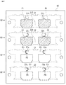
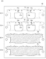
- FIG. FIG. 12 and FIG. 13 are plan views showing a process of forming a part of the core member according to the second embodiment by press punching. .
- FIG. 8 is a front view of the laminated core 25 of the rotating electrical machine according to the second embodiment, in which the laminated core 25 is arranged in the axial direction with the first core member 23 having a plurality of first core pieces 21 arranged in an annular shape as the uppermost stage. It is the figure seen from the top.
- the first core piece 21 is made of a magnetic plate such as an electromagnetic steel plate, and has an end 21A (hereinafter referred to as the first end 21A) having a convex shape at one end in the first circumferential direction X1.
- a concave end portion 21B (hereinafter referred to as a second end portion 21B) is provided at one end of the second circumferential direction X2 opposite to the first circumferential direction, and a through hole 21e as a connecting portion is provided in the first end portion 21A.
- the back yoke 21C has a magnetic pole tooth 21D that protrudes radially inward from the back yoke 21C.
- the 1st core member 23 fitted the 1st end part 21A and the 2nd end part 21B of the 1st core piece 21 adjacent to the circumferential direction, and has arrange
- FIG. 9 is a front view of the laminated core 25 of the rotating electrical machine according to the second embodiment, in which the laminated core 25 is axially arranged with the second core member 24 in which a plurality of second core pieces 12 are arranged in an annular shape being the uppermost stage. It is the figure seen from the top.
- the second core piece 22 is made of a magnetic plate such as an electromagnetic steel plate, and has an end 22A (hereinafter referred to as the first end 22A) having a convex shape at one end in the second circumferential direction X2.
- the first core member 13 and the circumferential direction are arranged in opposite directions.
- the laminated core 25 of the rotating electrical machine of the present embodiment is formed by alternately laminating the first core member 23 and the second core member 24 in the axial direction Z.
- a connecting shaft 25 f such as a pin is press-fitted into the through hole 21 e of the first core member 23 and the through hole 22 e of the second core member 24.
- the first core member 23 and the second core member 24 are coupled in the axial direction Z by the coupling portions 21e, 22e, and 25f, and the first core member 23 and the second core member 24 are rotated around the coupling portion. Can be made.
- the shapes of the butted portions 210a and 220a and the shapes of the butted portions 210b and 220b are the same, and the contact surfaces of the butted portions are flush with each other in the stacking direction.
- matching part may be alternately arrange
- the butted portion may be formed in a straight line instead of the uneven portion. This butt portion is finally fixed by a method such as welding or joining, and the laminated core 25 is formed in an annular shape.
- FIG. 11 shows a configuration in which the first core member 23 and the second core member 24 are rotated linearly around the connecting portions 21e, 22e, and 25f, and the first core member 23 and the second core member 24 are arranged linearly. It is a top view which shows a part.
- uneven portions 21k are formed on the front and back surfaces of the back yoke 21C of the first core piece 21, and on the front and back surfaces of the back yoke 22C of the second core piece 22 as shown in FIG. Is formed with an uneven portion 22k.
- the uneven portion 21k of the first core piece 21 and the uneven portion 22k of the second core piece 22 are fitted and connected in the axial direction Z.
- the first end 21 ⁇ / b> A of the first core piece 21 is formed at a radially outer position and has a convex curved first end surface 21 g based on the connecting portion 21 e, and a radially inner side.
- a planar second end face 21h is formed at a position on a straight line L1 connecting the axis center of the connecting portion 21e and the axis center O of the rotating electrical machine.
- the second end portion 21B of the first core piece 21 is formed with a concave curved third end surface 21i based on the connecting portion 21e of the adjacent first core piece 21 formed at a radially outer position, and a diameter.
- a planar fourth end face 21j formed on a straight line L2 formed at a position on the inner side in the direction and connecting the axis center of the connecting portion 21e and the axis center O of the rotating electrical machine is formed.
- the convex curved first end face 21g of the first core piece 21 abuts the concave curved third end face 21i of the adjacent first core piece 21 and the planar first shape of the first core piece 21 is flat.
- the two end faces 21h are in contact with the planar fourth end face 21j of the adjacent first core piece 21.
- the first end portion 22A of the second core piece 22 is formed at a radially outer position with a convex curved first end surface 22g with reference to the connecting portion 22e, and a radially inner side.
- a planar second end face 22h is formed on the straight line L3 formed at the position and connecting the axis center of the connecting portion 22e and the axis center O of the rotating electrical machine.
- the second end portion 22B of the second core piece 22 has a concave curved third end surface 22i based on the connecting portion 22e of the adjacent second core piece 22 formed at a radially outer position, and a diameter.
- a planar fourth end face 22j is formed on a straight line L4 formed at a position on the inner side in the direction and connecting the axis center of the connecting portion 22e and the axis center O of the rotating electrical machine. Then, the convex curved first end surface 22g of the second core piece 22 abuts on the concave curved third end surface 22i of the adjacent second core piece 22, and the planar first of the second core piece 22 is flat. The two end surfaces 22h are in contact with the planar fourth end surface 22j of the adjacent second core piece 22.
- the straight line L1 and the straight line L4 that pass through the axial center O of the rotating electrical machine overlap with each other in the axial direction of the rotating electrical machine, and the axial center O of the rotating electrical machine.
- the straight line L2 and the straight line L3 that pass through are positioned so as to overlap in the axial direction of the rotating electrical machine.
- the straight line L1 and the straight line L4 that pass through the axial center O of the rotating electrical machine do not overlap in the axial direction of the rotating electrical machine, or the straight line L2 and the straight line L3 that pass through the axial center O of the rotating electrical machine overlap in the axial direction of the rotating electrical machine. You may arrange so that it may not become.
- a portion located on the radially inner side of the contact surface formed by 22B is located in a plane including the central axis of the annular laminated core 15 and the central axes of the connecting portions 21e and 22e.
- annular laminated core 15 does not need to include the central axis of the connection parts 21e and 22e.
- the above-described butted portion is also located on the radially inner side of the contact surface formed by the convex butted portion 210a of the core piece 210A and the concave butted butted portion 210b of the core piece 210B that are adjacent in the circumferential direction. And a portion located on the radially inner side of the contact surface formed by the convex abutting portion 220a of the core piece 220A and the concave abutting portion 220b of the core piece 220B in the circumferential direction are annular.
- the laminated core 15 is preferably located in a plane including the central axis.
- FIGS. 12 and 13 show that three pieces of the first core piece 21 as the first core member 23 and the second core piece 22 as the second core member 24 are manufactured, respectively.
- the drawing is centered on the production of the first core piece 21 and the second core piece 22 at the center position.
- a portion P1 indicated by hatching in the drawing is press-punched to thereby form the magnetic teeth 21D of the first core piece 21.
- a peripheral portion, a second end surface 21h, and a fourth end surface 21j are formed.
- the portion P2 indicated by hatching in the drawing is press-punched to thereby form the magnetic teeth 22D of the second core piece 22
- a peripheral portion, a second end surface 22h, and a fourth end surface 22j are formed.
- a first end face of the first core piece 21 is pressed by punching a portion P3 indicated by hatching in the drawing. 21g and the 3rd end surface 21i are formed.
- the first end face 22g of the second core piece 22 is pressed by punching a portion P4 indicated by hatching in the drawing. And the 3rd end surface 22i is formed.
- a through hole 21e as a connecting portion is formed in the first end portion 21A of the first core piece 21 by press punching.
- a concave and convex portion 21k that can be fitted to the back surface of the back yoke 21C of the first core piece 21 by press punching is formed.
- a 3rd step which processes the 2nd core member 24 in the position shown by the arrow F2 of FIG.
- the first core member 23 is formed by press punching a portion P5 indicated by hatching in the drawing.
- the 2nd core member 24 is formed by press-punching the part P6 shown by hatching in a figure as a 4th step which processes the 2nd core member 24.
- the 1st core member 23 and the 2nd core member 24 which were formed as mentioned above are laminated
- a connecting shaft 25 f such as a pin is press-fitted into the through hole 21 e of the first core member 23 and the through hole 22 e of the second core member 24.
- the first core member 23 and the second core member 24 are warped in the radially outward direction.
- the magnetic pole teeth 21D of the first core piece 21 and the magnetic pole teeth 22D of the second core piece 22 are wound (not shown) and then rotated around the connecting shaft 25f to form an annular shape.
- the laminated core 25 of the rotating electrical machine with the windings is formed.
- the rotating electrical machine is formed by disposing a frame on the radially outer side of the laminated core 25 of the rotating electrical machine on which the winding is provided, and disposing a rotor having a rotating shaft on the radially inner side.
- the convex end of the first core piece and the concave end of the first core piece that are adjacent in the circumferential direction. And a portion located on the radially inner side of the abutting surface, and a convex end of the second core piece adjacent to the circumferential direction and a concave end of the second core piece. Since the portion located on the radially inner side of the contact surface is located in the plane including the central axis of the annular laminated core, it occurs between the first core pieces and the second core pieces adjacent in the circumferential direction. Since the force is generated only in the left-right direction and in the circumferential direction, the rigidity by the external force is increased, and the roundness of the laminated core of the rotating electrical machine is improved.
- a laminated core of a rotating electrical machine may be formed by laminating a body and a laminated body in which a plurality of second core members are laminated.
- Embodiment 3 FIG.
- the laminated core of the rotating electrical machine according to the third embodiment will be described.
- the description will focus on the features of the third embodiment, and the description of the same parts as in the above embodiment will be omitted as appropriate.
- FIG. 14 is a front view showing the configuration of the laminated core of the rotating electrical machine according to the third embodiment
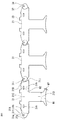
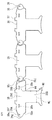
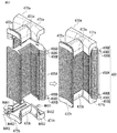
- FIG. 15 is a plan view showing a part of the configuration in which the core members of the second laminated body according to the third embodiment are arranged linearly
- 16 is a plan view showing a part of a configuration in which the core members of the first laminate according to the third embodiment are linearly arranged
- FIG. 17 is a core member of the first laminate and the second laminate according to the third embodiment.
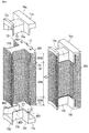
- FIG. 18 is a perspective view showing a state in which an insulator is attached to a core piece of a laminated core of a rotating electric machine according to a third embodiment.
- the laminated core 300 of the rotating electrical machine includes a first laminated body 300A in which a first core member 37 and a second core member 38 are laminated, and both axial sides of the first laminated body 300A. And a second laminated body 300B in which the first core member 33 and the second core member 34 are laminated.
- the 2nd laminated body 300B of the laminated core 300 of the rotary electric machine of this Embodiment is demonstrated.
- the first core member 33 has a plurality of first core pieces by fitting the first end 31 ⁇ / b> A and the second end 31 ⁇ / b> B of the first core piece 31 adjacent in the circumferential direction. 31 is arranged.
- the 1st core piece 31 is comprised from magnetic plates, such as an electromagnetic steel plate, and has the 1st end part 31A of convex shape in the 1st circumferential direction X1, and the 2nd end part 31B of concave shape in the 2nd circumferential direction X2.
- a back yoke 31C having connecting portions 31e and 31f at the first end 31A, and a magnetic pole tooth 31D protruding radially inward from the back yoke 31C.
- the second core member 34 is a member in which a plurality of second core pieces 32 are arranged by fitting the first end 32A and the second end 32B of the second core pieces 32 adjacent in the circumferential direction.
- the first core member 33 and the circumferential direction are arranged opposite to each other.
- the second laminated body 300B of the present embodiment is formed by alternately laminating the first core members 33 and the second core members 34 in the axial direction Z. Since the connection structure by the connection part of the connection part 31e, 31f of the 1st core member 33 and the 2nd core member 34 and the connection structure by the uneven part 31k are the same as that of Embodiment 1, the description is abbreviate
- the first end 31 ⁇ / b> A of the first core piece 31 is formed at a radially outer position and has a convex curved first end 31 g that is based on the connecting portions 31 e and 31 f. And a planar second end face 31h formed on a straight line L1 formed at a radially inner position and connecting the axial center of the coupling portions 31e and 31f and the axial center O of the rotating electrical machine. Further, the second end portion 31B of the first core piece 31 is formed with a concave curved third end surface 31i with reference to the connecting portions 31e and 31f of the adjacent first core piece 31 formed at a radially outer position.
- a planar fourth end face 31j is formed on a straight line L2 that is formed at a radially inner position and connects the shaft center of the coupling portions 31e and 31f and the shaft center O of the rotating electrical machine. Then, the convex curved first end surface 31g of the first core piece 31 abuts on the concave curved third end surface 31i of the adjacent first core piece 31, and the planar first of the first core piece 31 is flat. The two end surfaces 31h are in contact with the planar fourth end surface 31j of the adjacent first core piece 31.
- the planar third end surface and the planar fourth end surface are formed opposite to the first end surface, the second end surface, the third end surface, and the fourth end surface of the first core piece 31 described above in the circumferential direction. It is formed in the same way except for the point.
- the 1st laminated body 300A of the laminated core 300 of the rotary electric machine of this Embodiment is demonstrated.
- the first core member 37 has a plurality of first core pieces by fitting the first end 35 ⁇ / b> A and the second end 35 ⁇ / b> B of the first core pieces 35 adjacent in the circumferential direction. 35 is arranged.
- the 1st core piece 35 is comprised from magnetic plates, such as an electromagnetic steel plate, and has the 1st end part 35A of convex shape in the 1st circumferential direction X1, and the 2nd end part 35B of concave shape in the 2nd circumferential direction X2.
- a back yoke 35C having connecting portions 35e and 35f at the first end portion 35A, and a magnetic pole tooth 35D projecting radially inward from the back yoke 35C are provided.
- the second core member 38 has a plurality of second core pieces 32 arranged by fitting the first end 36A and the second end 36B of the second core pieces 36 adjacent in the circumferential direction.
- the first core member 37 and the circumferential direction are arranged opposite to each other.
- the second stacked body 300B of the present embodiment is formed by alternately stacking the first core members 37 and the second core members 38 in the axial direction Z. Since the connection structure by the connection part of the connection parts 35e and 35f of the 1st core member 37 and the 2nd core member 38 and the connection structure by the uneven
- the first end 35 ⁇ / b> A of the first core piece 35 is formed at a radially outer position and has a convex curved first end 35 g with respect to the connecting portions 35 e and 35 f. And a planar second end face 35h which is formed at a radially inner position and is on a straight line connecting the axial center of the coupling portions 35e and 35f and the axial center O of the rotating electrical machine.
- the second end portion 35B of the first core piece 35 has a concave curved third end surface 35i with reference to the connecting portions 35e and 35f of the adjacent first core piece 35 formed at a radially outer position.
- a flat fourth end face 35j is formed on a straight line that is formed at a radially inner position and connects the shaft centers of the coupling portions 35e and 35f and the shaft center O of the rotating electrical machine. Then, the convex curved first end surface 35g of the first core piece 35 abuts on the concave curved third end surface 35i of the adjacent first core piece 35, and the planar first of the first core piece 35 is flat. The two end surfaces 35h are in contact with the planar fourth end surface 35j of the adjacent first core piece 35.
- the third end surface having a shape and the fourth end surface having a planar shape are formed opposite to the first end surface, the second end surface, the third end surface, and the fourth end surface of the first core piece 35 described above in the circumferential direction. It is formed in the same way except for the point.
- connection in the axial direction Z between the first stacked body 300A and the second stacked body 300B is performed in the same manner as described above, and the connecting portion and the concavo-convex portion of the first stacked body 300A and the connecting portion of the second stacked body 300B. And it connects by connecting an uneven part.
- the radial width W4 of the back yoke of the first core piece 35 and the second core piece 36 constituting the first laminated body 300A is the first core constituting the second laminated body 300B.
- the piece 31 and the second core piece 32 are formed larger than the radial width W2 of the back yoke, and the difference (W4 ⁇ W2) is W5.
- the circumferential width W3 of the magnetic teeth of the first core piece 35 and the second core piece 36 constituting the first laminated body 300A is the first core piece 31 and the second core piece 32 constituting the second laminated body 300B.
- the magnetic teeth are formed larger than the circumferential width W1, and half of the difference (W3 ⁇ W1) is defined as W6.
- width W8 of the magnetic pole teeth tip portions of the first core piece 35 and the second core piece 36 constituting the first laminated body 300A is the first core piece 31 and the second core piece 32 constituting the second laminated body 300B. Is formed to be larger than the width W7 of the tip of the magnetic teeth, and the difference (W8 ⁇ W7) is defined as W9.
- the first stacked body 300A and the second stacked body 300B are provided with a core piece having a butt portion as in the first and second embodiments, and the shape and dimensional relationship of the core piece having the butt portion have been described above.
- the shapes and dimensional relationships of the first core piece 35 and the second core piece 36 of the first laminated body 300A and the first core piece 31 and the second core piece 32 of the second laminated body 300B are similarly applied.
- FIG. 18 is a perspective view showing a state where the insulators 70a and 70b are attached to the laminated core 300 of the rotating electrical machine according to the third embodiment.
- the insulators 70a and 70b include radially outer flanges 71a and 71b, radially inner flanges 72a and 72b, and winding mounting portions 73a and 73b.
- the differences W5, W6, and W9 described above are the thickness W50 of the winding side wall of the radially outer flanges 71a and 71b of the insulators 70a and 70b, the thickness W60 and the diameter of the winding mounting portions 73a and 73b, respectively.
- the design is made such that the winding side wall thickness W90 of the direction inner flange portions 72a and 72b is equal to that of the laminated core 300, there is an advantage that the steps due to the attachment of the insulators 70a and 70b to the laminated core 300 are eliminated and the winding can be performed smoothly. Note that after the insulators 70a and 70b are mounted on the laminated core 300, an insulating paper (not shown) is mounted and winding is performed.
- the convex shape of the first core piece adjacent in the circumferential direction is obtained.
- the portion located on the radially inner side of the contact surface formed by the end portion and the concave end portion of the first core piece, and the convex end portion and the second portion of the second core piece adjacent in the circumferential direction Since the portion located on the radially inner side of the contact surface formed by the concave end of the core piece is located in the plane including the central axis of the annular laminated core, it is adjacent in the circumferential direction. Since the force generated between the one core pieces and between the second core pieces is generated only in the left and right directions and in the circumferential direction, the rigidity by the external force is increased, and the roundness of the laminated core of the rotating electrical machine is improved.
- the lengths of the linear end faces of the first core piece and the second core piece adjacent in the circumferential direction are not shifted regardless of the radial width of the back yoke of the first core piece and the second core piece. , Increase in magnetic resistance can be prevented.
- the 2nd laminated body of this Embodiment is formed by laminating
- stacked several 1st core members You may comprise a 2nd laminated body by respectively laminating
- a second laminated body formed by laminating one of the first core member and the second core member in the axial direction Z is formed on one end side in the axial direction of the first laminated body, and the axial direction of the first laminated body, etc.
- a second laminate formed by laminating the other of the first core member and the second core member in the axial direction Z may be formed on the end side.
- the 1st laminated body of this Embodiment is formed by laminating
- stacked several 1st core members You may comprise a 1st laminated body by laminating
- Embodiment 4 FIG.
- the laminated core of the rotating electrical machine according to the fourth embodiment will be described.
- the description will focus on the features of the fourth embodiment, and the description of the same parts as in the above embodiment will be omitted as appropriate.
- FIG. 24 is a front view showing the configuration of the laminated core of the rotating electrical machine according to the fourth embodiment
- FIG. 25 is a plan view showing a part of the configuration in which the core members of the laminated body according to the fourth embodiment are arranged linearly
- FIG. FIG. 27 is a plan view showing a part of a configuration in which core members of a plurality of types of laminated bodies according to Embodiment 4 are linearly arranged
- FIG. 27 shows a state where an insulator is attached to a core piece of a laminated core of a rotating electrical machine according to Embodiment 4.
- FIG. 24 is a front view showing the configuration of the laminated core of the rotating electrical machine according to the fourth embodiment
- FIG. 25 is a plan view showing a part of the configuration in which the core members of the laminated body according to the fourth embodiment are arranged linearly
- FIG. 27 is a plan view showing a part of a configuration in which core members of a plurality of types of laminated bodies according to Embodiment
- the laminated core 400 of the rotating electrical machine of the present embodiment is configured by laminating a first laminated body 400A, a second laminated body 400B, a third laminated body 400C, and a fourth laminated body 400D.
- the Each of the first stacked body 400A to the fourth stacked body 400D includes a stacked first core member 47 and second core member 48.
- the first laminated body 400A is disposed at the center in the axial direction
- the second laminated body 400B, the third laminated body 400C, and the fourth laminated body 400D are sequentially disposed at both ends in the axial direction.
- the first laminated body 400A to the fourth laminated body 400D include the circumferential width of the magnetic pole teeth of the first core member 47 and the second core member 48, and the diameters of the back yokes of the first core member 47 and the second core member 48.
- the direction width is narrowed in stages as it approaches both ends in the axial direction.
- the second stacked body 400B to the fourth stacked body 400D are collectively referred to as a “second stacked body”.
- the first core member 47 is indicated by hatching.
- the connection structure in which the first core member 47 and the second core member 48 are connected in the circumferential direction is the same as that in the first embodiment, and thus the description thereof is omitted.
- a certain flat first end face 45g and second end face 45h are formed. The first end face 45g and the second end face 45h are in contact with each other. This is the same in any of the first stacked body 400A to the fourth stacked body 400D.
- the radial width W11a of the back yoke of the first core member 47 and the second core member 48 constituting the first laminated body 400A is the first core constituting the second laminated body 400B.
- the member 47 and the second core member 48 are formed larger than the radial width W11b of the back yoke, and the difference (W11a ⁇ W11b) is defined as W13ab.
- the radial width W11b of the back yoke of the first core member 47 and the second core member 48 constituting the second laminated body 400B is the back of the first core member 47 and the second core member 48 constituting the third laminated body 400C.
- the yoke is formed larger than the radial width W11c, and the difference (W11b-W11c) is defined as W13bc.
- the radial width W11c of the back yoke of the first core member 47 and the second core member 48 constituting the third laminated body 400C is the back of the first core member 47 and the second core member 48 constituting the fourth laminated body 400D.
- the yoke is formed larger than the radial width W11d, and the difference (W11c ⁇ W11d) is defined as W13cd.
- the circumferential width W12a of the magnetic teeth of the first core member 47 and the second core member 48 constituting the first laminated body 400A is the first core member 47 and the second core member 48 constituting the second laminated body 400B. Is formed to be larger than the circumferential width W12b of the magnetic teeth, and half of the difference (W12a ⁇ W12b) is defined as W14ab.
- the circumferential width W12b of the magnetic pole teeth of the first core member 47 and the second core member 48 constituting the second laminated body 400B is the magnetic pole of the first core member 47 and the second core member 48 constituting the third laminated body 400C. It is formed larger than the circumferential width W12c of the teeth, and half of the difference (W12b ⁇ W12c) is defined as W14bc.
- the circumferential width W12c of the magnetic teeth of the first core member 47 and the second core member 48 constituting the third laminated body 400C is the magnetic pole of the first core member 47 and the second core member 48 constituting the fourth laminated body 400D. It is formed larger than the circumferential width W12d of the teeth, and half of the difference (W12c ⁇ W12d) is defined as W14cd.
- first stacked body 400A to the fourth stacked body 400D are provided with the core pieces having the butted portions 420a and 420b as in the first and second embodiments, and the core pieces having the butted portions 420a and 420b.
- shape and dimensional relationship the shapes and dimensional relationships of the first core member 47 and the second core member 48 of the first stacked body 400A to the fourth stacked body 400D are similarly applied.
- FIG. 27 is a perspective view showing a state where the insulators 470a and 470b are attached to the laminated core 400 of the rotating electrical machine according to the fourth embodiment.
- the insulators 470a and 470b include radial outer flanges 471a and 471b, radial inner flanges 472a and 472b, and winding mounting portions 473a and 473b.
- the thicknesses of the winding side walls of the radially outer flange portions 471a and 471b are set in three stages, and the thickness W451 of the winding side wall closest to the axial center of the laminated core 400 is the first laminated body 400A and the second laminated layer.
- the same value as the difference W13ab in the radial width of the back yoke of the body 400B is set.
- the thickness W452 of the winding side wall closest to the axial center of the laminated core 400 is the back of the first laminated body 400A and the second laminated body 400B.
- the difference is set to the sum of the radial width difference W13ab of the yoke and the radial width difference W13bc of the back yokes of the second stacked body 400B and the third stacked body 400C.
- the thickness W453 of the winding side wall farthest from the axial center side of the laminated core 400 is the back yoke of the first laminated body 400A and the second laminated body 400B.
- the radial width difference W13ab, the radial width difference W13bc of the second stacked body 400B and the third stacked body 400C, and the radial width of the back yoke of the third stacked body 400C and the fourth stacked body 400D The sum is set to the difference W13cd.
- the thicknesses of the winding mounting portions 473a and 473b are set in three stages, and the thickness W461 of the winding mounting portions 473a and 473b closest to the axial center of the laminated core 400 is the first laminated body 400A and the second laminated layer. It is set to the same value as half W14ab of the difference in the circumferential width of the magnetic teeth of body 400B.
- the difference W462 between the thicknesses of the winding mounting portions 473a and 473b closest to the axial center of the laminated core 400 and the thicknesses of the second closest winding mounting portions 473a and 473b is the second stacked body 400B and the third stacked layer. It is set to the same value as half W14bc of the difference in the circumferential width of the magnetic teeth of body 400C.
- the difference W463 between the thicknesses of the winding mounting portions 473a and 473b that is the second closest from the axial center side of the laminated core 400 and the thicknesses of the third winding mounting portions 473a and 473b are It is set to the same value as the half W14cd of the difference in the circumferential width of the magnetic teeth of the four-layered body 400D.
- the radial width of the back yoke and the width of the magnetic teeth of the laminated core 400 are changed stepwise.
- it is the same as that of Embodiment 3, and has the same connection structure as Embodiment 3, the shape of a connection part, and the end surface formed in the radial inside of a connection part. Therefore, the present embodiment has the same effects as those of the configuration of the third embodiment. That is, since the force generated between the first core members 47 and the second core members 48 adjacent in the circumferential direction is generated only in the left and right directions and in the circumferential direction, the rigidity by the external force is increased, and the laminated core 400 of the rotating electrical machine Roundness is improved.
- the lengths of the end faces 45g and 45h of the first core member 47 and the second core member 48 adjacent to each other in the circumferential direction regardless of the radial width of the back yoke of the first core member 47 and the second core member 48. Therefore, increase in magnetic resistance can be prevented.
- the first stacked body 400A to the fourth stacked body 400D of the present embodiment are formed by alternately stacking the first core member 47 and the second core member 48 in the axial direction Z.
- a part or all of the first laminate 400A to the fourth laminate 400D is configured. May be.
Landscapes
- Engineering & Computer Science (AREA)
- Power Engineering (AREA)
- Manufacturing & Machinery (AREA)
- Iron Core Of Rotating Electric Machines (AREA)
Abstract
積層コア(15)が環状に構成された場合に、周方向に隣接する第1コア片(11)の凸形状の端部(11A)と第1コア片(11)の凹形状の端部(11B)とにより形成された当接面の径方向内側に位置する部分、および、周方向に隣接する第2コア片(12)の凸形状の端部(12A)と第2コア片(12)の凹形状の端部(12B)とにより形成された当接面の径方向内側に位置する部分が、環状の積層コア(15)の中心軸を含む面内に位置している。
Description
本願は、回転電機の積層コア、およびその積層コアを備えた回転電機に関するものである。
従来、回転電機の積層コアとして、複数のコア片の端部同士を連結して環状に構成され、上記コア片は、上記連結方向に対してほぼ直角方向に磁極ティースが突出して形成され、上記端部のいずれか一端側に連結部が形成されるとともに、上記一端側の第1の端面は上記連結部を中心とした円弧状に形成され、他端側には相隣なるものの上記第1の端面と嵌合可能な第2の端面が形成され、上記コア片を上記両端面を介して帯状に配列してなる第1のコア部材と、上記コア片が上記第1のコア部材とは上記連結方向に互い違いに帯状に配列してなる第2のコア部材を、上記各コア片の積層方向に相隣なる端部同士が重なるように積層するとともに、上記連結部同士を回転自在に連結し上記磁極ティースを内側として上記環状に形成したコアが開示されている。(例えば、特許文献1参照)
上記従来の技術では、第1のコア部材および第2のコア部材において、一端側の第1の端面は連結部を中心とした円弧状に形成され、他端側には相隣なるものの第1の端面と嵌合可能な第2の端面が形成されている。このように第1および第2の端面は円弧状に形成されるので、製作上形状のばらつきが発生しやすい。また、連結部の形成位置のばらつきも発生しやすい。
そして、これら形状および形成位置のばらつきによって、周方向に隣接するコア片を連結部を中心として環状に変形させたとき、周方向に隣接するコア片同士の中心と回転軸中心を結ぶ線の成す角度が安定しないため、回転電機の積層コアとしての真円度が悪くなっていた。また、回転電機の積層コアを環状に固定した時、外力に対する剛性が低いという課題があった。
本願は、上記のような課題を解決するための技術を開示するものであり、真円度が高く、外力に対する剛性が高い回転電機の積層コアおよび回転電機を提供することを目的とする。
本願に開示される回転電機の積層コアは、第1周方向の一端に連結部を有する凸形状の端部および第2周方向の他端に凹形状の端部を有するバックヨークと、前記バックヨークから径方向内側に突出する磁極ティースを有する第1コア片を複数並べ、前記第1コア片の凸形状の端部と隣接する前記第1コア片の凹形状の端部を嵌合させて形成された第1コア部材と、
前記第2周方向の一端に連結部を有する凸形状の端部および前記第1周方向の他端に凹形状の端部を有するバックヨークと、前記バックヨークから径方向内側に突出する磁極ティースを有する第2コア片を複数並べ、前記第2コア片の凸形状の端部と隣接する第2コア片の凹形状の端部を嵌合させて形成された第2コア部材と、を備え
前記第1コア部材を含む部材と前記第2コア部材を含む部材とが、前記第1コア片の凸形状の端部と前記第2コア片の凸形状の端部とを、軸方向に重なり合わせて連結部により回動可能に連結させて、積層された回転電機の積層コアであって、
前記積層コアが環状に構成された場合に、周方向に隣接する前記第1コア片の凸形状の端部と前記第1コア片の凹形状の端部とにより形成された当接面の径方向内側に位置する部分、および、周方向に隣接する前記第2コア片の凸形状の端部と前記第2コア片の凹形状の端部とにより形成された当接面の径方向内側に位置する部分が、前記環状の積層コアの中心軸を含む面内に位置している。
前記第2周方向の一端に連結部を有する凸形状の端部および前記第1周方向の他端に凹形状の端部を有するバックヨークと、前記バックヨークから径方向内側に突出する磁極ティースを有する第2コア片を複数並べ、前記第2コア片の凸形状の端部と隣接する第2コア片の凹形状の端部を嵌合させて形成された第2コア部材と、を備え
前記第1コア部材を含む部材と前記第2コア部材を含む部材とが、前記第1コア片の凸形状の端部と前記第2コア片の凸形状の端部とを、軸方向に重なり合わせて連結部により回動可能に連結させて、積層された回転電機の積層コアであって、
前記積層コアが環状に構成された場合に、周方向に隣接する前記第1コア片の凸形状の端部と前記第1コア片の凹形状の端部とにより形成された当接面の径方向内側に位置する部分、および、周方向に隣接する前記第2コア片の凸形状の端部と前記第2コア片の凹形状の端部とにより形成された当接面の径方向内側に位置する部分が、前記環状の積層コアの中心軸を含む面内に位置している。
本願に開示される回転電機は、環状に構成された前記回転電機の積層コアと、前記回転電機の積層コアの前記磁極ティースに巻き回された巻線と、前記回転電機の積層コアの径方向内側に配置された回転子を備えたものである。
本願に開示される回転電機の積層コアおよび回転電機によれば、真円度が高く、外力に対する剛性が高い回転電機の積層コアおよび回転電機を提供することができる。
本願の実施の形態を説明する前に、本願が解決しようとする課題を明確にするために、本願の前提となる参考技術を図19~図23に基づいて説明する。また、本願の説明において、周方向X、径方向Y、軸方向Zは、それぞれ回転電機を基準とした周方向X、径方向Y、軸方向Zを意味している。
参考技術.
図19および図20は本願の参考技術による回転電機の積層コアの構成を示す正面図、図21は本願の参考技術によるコア部材同士の連結部の構成を示す一部断面図、図22および図23は本願の参考技術による回転電機の積層コアの不具合を説明するための一部詳細図である。なお、コア部材とは、下記に説明する第1コア部材および第2コア部材を総称したものとする。
図19および図20は本願の参考技術による回転電機の積層コアの構成を示す正面図、図21は本願の参考技術によるコア部材同士の連結部の構成を示す一部断面図、図22および図23は本願の参考技術による回転電機の積層コアの不具合を説明するための一部詳細図である。なお、コア部材とは、下記に説明する第1コア部材および第2コア部材を総称したものとする。
図19において、第1コア部材113は、周方向に隣接する第1コア片111の第1端部111Aと第2端部111Bを嵌合させて複数の第1コア片111を環状に配置させたものである。
第1コア片111は、電磁鋼板等の磁性板から構成され、第1周方向X1に凸形状の第1端部111Aおよび第2周方向X2に凹形状の第2端部111Bを有するとともに第1端部111Aに連結部111e、111fを有するバックヨーク111Cと、バックヨーク111Cから径方向内側に突出する磁極ティース111Dを有する。
第1コア片111は、電磁鋼板等の磁性板から構成され、第1周方向X1に凸形状の第1端部111Aおよび第2周方向X2に凹形状の第2端部111Bを有するとともに第1端部111Aに連結部111e、111fを有するバックヨーク111Cと、バックヨーク111Cから径方向内側に突出する磁極ティース111Dを有する。
図20に示すように、第2コア部材114は、周方向に隣接する第2コア片112の第1端部112Aと第2端部112Bを嵌合させて複数の第2コア片112を環状に配置させたものであり、図19に示す第1コア部材113と周方向が反対向きに配置されたものである。
第2コア片112は、電磁鋼板等の磁性板から構成され、第2周方向X2に凸形状の第1端部112Aおよび第1周方向X1に凹形状の第2端部112Bを有するとともに第1端部112Aに連結部112e、112fを有するバックヨーク112Cと、バックヨーク112Cから径方向内側に突出する磁極ティース112Dを有する。
第2コア片112は、電磁鋼板等の磁性板から構成され、第2周方向X2に凸形状の第1端部112Aおよび第1周方向X1に凹形状の第2端部112Bを有するとともに第1端部112Aに連結部112e、112fを有するバックヨーク112Cと、バックヨーク112Cから径方向内側に突出する磁極ティース112Dを有する。
本願の参考技術による回転電機の積層コア120は、第1コア部材113および第2コア部材114を軸方向Zに交互に積層して形成される。図21のコア部材同士の連結部の一部断面図に示すように、第1コア部材113の連結部111e、111fは、表面に形成された凹部111eおよび裏面に形成された凸部111fから構成され、第2コア部材114の連結部112e、112fは、表面に形成された凹部112eおよび裏面に形成された凸部112fから構成されている。第1コア部材113および第2コア部材114を積層する際に、第1コア部材113の連結部である凸部111fが第2コア部材14の連結部である凹部112eに嵌合し、また、第2コア部材114の連結部である凸部112fが第1コア部材113の連結部である凹部111eに嵌合する。その結果、第1コア部材113の連結部111e、111fと第2コア部材114の連結部112e、112fを当該連結部回りに回動可能に連結させることができる。
なお、図19に示すように、第1コア片111のバックヨーク111Cの表裏面には凹凸部111kが形成され、図20に示すように、第2コア片112のバックヨーク112Cの表裏面には凹凸部112kが形成されている。そして、第1コア部材113および第2コア部材114を積層する際には、軸方向Zに第1コア片111の凹凸部111kと第2コア片112の凹凸部112kが嵌合して連結される。
また、図19に示すように、第1コア片111の第1端部111Aには、連結部111e、111fを基準とした凸型曲面状の第1端面111gが形成されている。
また、第1コア片111の第2端部111Bには、周方向に隣接する第1コア片111の連結部111e、111fを基準とした凹型曲面状の第3端面111iが形成されている。
そして、第1コア片111の凸型曲面状の第1端面111gが、周方向に隣接する第1コア片111の凹型曲面状の第3端面111iと当接している。
また、第1コア片111の第2端部111Bには、周方向に隣接する第1コア片111の連結部111e、111fを基準とした凹型曲面状の第3端面111iが形成されている。
そして、第1コア片111の凸型曲面状の第1端面111gが、周方向に隣接する第1コア片111の凹型曲面状の第3端面111iと当接している。
図20に示すように、第2コア片112の第1端部112Aには、連結部112e、112fを基準とした凸型曲面状の第1端面112gが形成されている。
また、第2コア片112の第2端部112Bには、隣接する第2コア片112の連結部112e、112fを基準とした凹型曲面状の第3端面112iが形成されている。
そして、第2コア片112の凸型曲面状の第1端面112gが、周方向に隣接する第2コア片112の凹型曲面状の第3端面112iと当接している。
また、第2コア片112の第2端部112Bには、隣接する第2コア片112の連結部112e、112fを基準とした凹型曲面状の第3端面112iが形成されている。
そして、第2コア片112の凸型曲面状の第1端面112gが、周方向に隣接する第2コア片112の凹型曲面状の第3端面112iと当接している。
本願の参考技術による回転電機の積層コアは以上のように構成され、第1コア部材113および第2コア部材114を、第1コア片111の連結部111e、111fおよび第2コア片112の連結部112e、112fを回動中心として環状に配列して、第1コア片111の第1端面111gが、周方向に隣接する第1コア片111の第3端面111iに当接するとともに、第2コア片112の第1端面112gが、周方向に隣接する第2コア片112の第3端面112iに当接するように構成される。
しかしながら、第1コア片111の第1端面111gおよび第2コア片112の第1端面112gは凸型曲面状であり、第1コア片111の第3端面111iおよび第2コア片112の第3端面112iは凹型曲面状であるので、製作上形状のばらつきが発生しやすい。また、連結部111e、111f、112e、112fとしての凹凸部の形成位置のばらつきも発生しやすい。
また、これら形状および形成位置のばらつきによって、周方向に隣接する第1コア片111および第2コア片112を連結部を中心として環状に変形させたとき、連結部としての凹凸部111e、111f、112e、112fの接触状態がばらつき、図22に示すように周方向に隣接する第1コア片111の間の径方向外側に隙間150を生じたり、図23に示すように周方向に隣接する第1コア片111の間の径方向内側に隙間160を生じたりする。
そのため、周方向に隣接する第1コア片111の中心と回転軸中心を結ぶ線Ce1およびCe2の成す角度θ1が安定しなくなり、回転電機の積層コア120としての真円度が悪くなっていた。また、回転電機の積層コア120を環状に固定した時、上記のように隙間150、160が生ずるので、外力に対する剛性が低いという課題があった。
本願の実施の形態は、上記の参考技術の課題を解消するためになされたものであり、以下、図面に基づいて詳細に説明する。
実施の形態1.
図1および図2は実施の形態1による回転電機の積層コアの構成を示す正面図、図3は実施の形態1によるコア部材同士の連結部の構成を示す一部断面図、図4は実施の形態1によるコア部材を直線状に配置した構成の一部を示す平面図、図5および図6は実施の形態1によるコア部材の一部をプレス打抜きにより形成する工程を示す平面図、図7は実施の形態1による回転電機の構成を示す正面図である。
図1および図2は実施の形態1による回転電機の積層コアの構成を示す正面図、図3は実施の形態1によるコア部材同士の連結部の構成を示す一部断面図、図4は実施の形態1によるコア部材を直線状に配置した構成の一部を示す平面図、図5および図6は実施の形態1によるコア部材の一部をプレス打抜きにより形成する工程を示す平面図、図7は実施の形態1による回転電機の構成を示す正面図である。
図1は、実施の形態1の回転電機の積層コア15の正面図であって、複数の第1コア片11を環状に配置させた第1コア部材13を最上段として積層コア15を軸方向上方から視た図である。
図1に示すように、第1コア片11は、電磁鋼板等の磁性板から構成され、第1周方向X1の一端に凸形状の端部11A(以下、第1端部11Aと称す)および第1周方向と反対方向の第2周方向X2の一端に凹形状の端部11B(以下、第2端部11Bと称す)を有するとともに第1端部11Aに連結部11e、11fを有するバックヨーク11Cと、バックヨーク11Cから径方向内側に突出する磁極ティース11Dを有する。
そして、第1コア部材13は、周方向に隣接する第1コア片11の第1端部11Aと第2端部11Bを嵌合させて複数の第1コア片11を配置させたものである。
図1に示すように、第1コア片11は、電磁鋼板等の磁性板から構成され、第1周方向X1の一端に凸形状の端部11A(以下、第1端部11Aと称す)および第1周方向と反対方向の第2周方向X2の一端に凹形状の端部11B(以下、第2端部11Bと称す)を有するとともに第1端部11Aに連結部11e、11fを有するバックヨーク11Cと、バックヨーク11Cから径方向内側に突出する磁極ティース11Dを有する。
そして、第1コア部材13は、周方向に隣接する第1コア片11の第1端部11Aと第2端部11Bを嵌合させて複数の第1コア片11を配置させたものである。
図2は、実施の形態1の回転電機の積層コア15の正面図であって、複数の第2コア片12を環状に配置させた第2コア部材14を最上段として積層コア15を軸方向上方から視た図である。
図2に示すように、第2コア片12は、電磁鋼板等の磁性板から構成され、第2周方向X2の一端に凸形状の端部12A(以下、第1端部12Aと称す)および第1周方向X1の一端に凹形状の端部12B(以下、第2端部12Bと称す)を有するとともに第1端部12Aに連結部12e、12fを有するバックヨーク12Cと、バックヨーク12Cから径方向内側に突出する磁極ティース12Dを有する。
そして、第2コア部材14は、周方向に隣接する第2コア片12の第1端部12Aと第2端部12Bを嵌合させて複数の第2コア片12を配置させたものであり、第1コア部材13と周方向が反対向きに配置されたものである。
図2に示すように、第2コア片12は、電磁鋼板等の磁性板から構成され、第2周方向X2の一端に凸形状の端部12A(以下、第1端部12Aと称す)および第1周方向X1の一端に凹形状の端部12B(以下、第2端部12Bと称す)を有するとともに第1端部12Aに連結部12e、12fを有するバックヨーク12Cと、バックヨーク12Cから径方向内側に突出する磁極ティース12Dを有する。
そして、第2コア部材14は、周方向に隣接する第2コア片12の第1端部12Aと第2端部12Bを嵌合させて複数の第2コア片12を配置させたものであり、第1コア部材13と周方向が反対向きに配置されたものである。
本実施の形態の回転電機の積層コア15は、第1コア部材13および第2コア部材14を軸方向Zに交互に積層して形成される。図3のコア部材同士の連結部の一部断面図に示すように、第1コア部材13の連結部11e、11fは、表面に形成された凹部11eおよび裏面に形成された凸部11fから構成され、第2コア部材14の連結部12e、12fは、表面に形成された凹部12eおよび裏面に形成された凸部12fから構成されている。第1コア部材13および第2コア部材14を積層する際に、第1コア部材13の連結部である凸部11fが第2コア部材14の連結部である凹部12eに嵌合し、また、第2コア部材14の連結部である凸部12fが第1コア部材13の連結部である凹部11eに嵌合する。その結果、第1コア部材13の連結部11e、11fと第2コア部材14の連結部12e、12fを当該連結部回りに回動可能に連結させることができる。
なお、図1に示すように、第1コア部材13の第1コア片11に隣接して、バックヨーク11Cの周方向の一端に連結部11e、11fを有さない突き合わせ部110aおよび110bを有するコア片110Aおよび110Bを備えている。また、図2に示すように、第2コア部材14の第2コア片12に隣接して、バックヨーク12Cの周方向の一端に連結部12e、12fを有さない突き合わせ部120aおよび120bを有するコア片120Aおよび120Bを備えている。本実施の形態では、突き合わせ部110aと120aの形状、並びに突き合わせ部110bと120bの形状は同じであり、突き合わせ部同士の当接面は、積層方向において面一となっている。なお、積層毎に突き合わせ部の凸部と凹部が交互に配置されていてもよい。また、突き合わせ部は凹凸部ではなく直線状に形成されていてもよい。この突き合わせ部は、最終的に溶接、接合などの方法で固着され、積層コア15を環状に構成する。
図4は、第1コア部材13の連結部11e、11fと第2コア部材14の連結部12e、12fを当該連結部回りに回動させて、第1コア部材13および第2コア部材14を直線状に配置した構成の一部を示す平面図である。
また、図1に示すように、第1コア片11のバックヨーク11Cに表裏面には凹凸部11kが形成され、図2に示すように、第2コア片12のバックヨーク12Cの表裏面には凹凸部12kが形成されている。そして、第1コア部材13および第2コア部材14を積層する際には、軸方向Zに第1コア片11の凹凸部11kと第2コア片12の凹凸部12kが嵌合して連結される。
図1に戻って、第1コア片11の第1端部11Aには、径方向外側の位置に形成され連結部11e、11fを基準とした凸型曲面状の第1端面11gと、径方向内側の位置に形成され連結部11e、11fの軸中心と回転電機の軸中心Oを結ぶ直線L1上にある平面状の第2端面11hとが形成されている。
また、第1コア片11の第2端部11Bには、径方向外側の位置に形成され隣接する第1コア片11の連結部11e、11fを基準とした凹型曲面状の第3端面11iと、径方向内側の位置に形成され連結部11e、11fの軸中心と回転電機の軸中心Oを結ぶ直線L2上にある平面状の第4端面11jとが形成されている。
そして、第1コア片11の凸型曲面状の第1端面11gが、隣接する第1コア片11の凹型曲面状の第3端面11iと当接するとともに、第1コア片11の平面状の第2端面11hが、隣接する第1コア片11の平面状の第4端面11jに当接している。
また、第1コア片11の第2端部11Bには、径方向外側の位置に形成され隣接する第1コア片11の連結部11e、11fを基準とした凹型曲面状の第3端面11iと、径方向内側の位置に形成され連結部11e、11fの軸中心と回転電機の軸中心Oを結ぶ直線L2上にある平面状の第4端面11jとが形成されている。
そして、第1コア片11の凸型曲面状の第1端面11gが、隣接する第1コア片11の凹型曲面状の第3端面11iと当接するとともに、第1コア片11の平面状の第2端面11hが、隣接する第1コア片11の平面状の第4端面11jに当接している。
図2に戻って、第2コア片12の第1端部12Aには、径方向外側の位置に形成され連結部12e、12fを基準とした凸型曲面状の第1端面12gと、径方向内側の位置に形成され連結部12e、12fの軸中心と回転電機の軸中心Oを結ぶ直線L3上にある平面状の第2端面12hとが形成されている。
また、第2コア片12の第2端部12Bには、径方向外側の位置に形成され隣接する第2コア片12の連結部12e、12fを基準とした凹型曲面状の第3端面12iと、径方向内側の位置に形成され連結部12e、12fの軸中心と回転電機の軸中心Oを結ぶ直線L4上にある平面状の第4端面12jとが形成されている。
そして、第2コア片12の凸型曲面状の第1端面12gが、隣接する第2コア片12の凹型曲面状の第3端面12iと当接するとともに、第2コア片12の平面状の第2端面12hが、隣接する第2コア片12の平面状の第4端面12jに当接している。
また、第2コア片12の第2端部12Bには、径方向外側の位置に形成され隣接する第2コア片12の連結部12e、12fを基準とした凹型曲面状の第3端面12iと、径方向内側の位置に形成され連結部12e、12fの軸中心と回転電機の軸中心Oを結ぶ直線L4上にある平面状の第4端面12jとが形成されている。
そして、第2コア片12の凸型曲面状の第1端面12gが、隣接する第2コア片12の凹型曲面状の第3端面12iと当接するとともに、第2コア片12の平面状の第2端面12hが、隣接する第2コア片12の平面状の第4端面12jに当接している。
なお、本実施の形態では、図1および図2に示すように、回転電機の軸中心Oを通る直線L1と直線L4は回転電機の軸方向において重なるように、および、回転電機の軸中心Oを通る直線L2と直線L3は回転電機の軸方向において重なるように、それぞれ位置している。ただし、回転電機の軸中心Oを通る直線L1と直線L4は回転電機の軸方向において重ならないように、または、回転電機の軸中心Oを通る直線L2と直線L3は回転電機の軸方向において重ならないように、配置してもよい。
すなわち、積層コア15が環状に構成された場合に、周方向に隣接する第1コア片11の凸形状の第1端部11Aと第1コア片11の凹形状の第2端部11Bとにより形成された当接面の径方向内側に位置する部分、および、周方向に隣接する第2コア片12の凸形状の第1端部12Aと第2コア片12の凹形状の第2端部12Bとにより形成された当接面の径方向内側に位置する部分が、環状の積層コア15の中心軸および連結部11e、11f、12e、12fの中心軸を含む面内に位置している。
なお、環状の積層コア15の中心軸を含む上記面は、連結部11e、11f、12e、12fの中心軸を含まなくともよい。
なお、環状の積層コア15の中心軸を含む上記面は、連結部11e、11f、12e、12fの中心軸を含まなくともよい。
また、上述した突き合わせ部においても、周方向に隣接するコア片110Aの凸形状の突き合わせ部110aとコア片110Bの凹形状の突き合わせ部110bとにより形成された当接面の径方向内側に位置する部分、および、周方向に隣接するコア片120Aの凸形状の突き合わせ部120aとコア片120Bの凹形状の突き合わせ部120bとにより形成された当接面の径方向内側に位置する部分が、環状の積層コア15の中心軸を含む面内に位置していることが好ましい。
次に、上記のように構成された実施の形態1による回転電機の積層コア15の製造方法について、図5および図6に基づいて説明する。なお、図5および図6では、第1コア部材13としての第1コア片11および第2コア部材14としての第2コア片12を、それぞれ3個分製作しているところを示し、特に、中央位置の第1コア片11および第2コア片12の製作を中心に描いている。
まず、図5の矢印A1に示す位置において、第1コア部材13を加工する第1段階として、図中のハッチングで示す部分P1をプレス打ち抜きすることにより、第1コア片11の磁極ティース11Dの周辺部、第2端面11hおよび第4端面11jを形成する。
そして、図5の矢印B1に示す位置において、第2コア部材14を加工する第1段階として、図中のハッチングで示す部分P2をプレス打ち抜きすることにより、第2コア片12の磁極ティース12Dの周辺部、第2端面12hおよび第4端面12jを形成する。
そして、図5の矢印B1に示す位置において、第2コア部材14を加工する第1段階として、図中のハッチングで示す部分P2をプレス打ち抜きすることにより、第2コア片12の磁極ティース12Dの周辺部、第2端面12hおよび第4端面12jを形成する。
次に、図5の矢印C1に示す位置において、第1コア部材13を加工する第2段階として、図中のハッチングで示す部分P3をプレス打ち抜きすることにより、第1コア片11の第1端面11gおよび第3端面11iを形成する。
そして、図5の矢印D1に示す位置において、第2コア部材14を加工する第2段階として、図中のハッチングで示す部分P4をプレス打ち抜きすることにより、第2コア片12の第1端面12gおよび第3端面12iを形成する。
そして、図5の矢印D1に示す位置において、第2コア部材14を加工する第2段階として、図中のハッチングで示す部分P4をプレス打ち抜きすることにより、第2コア片12の第1端面12gおよび第3端面12iを形成する。
次に、図6の矢印E1に示す位置において、第1コア部材13を加工する第3段階として、第1コア片11の第1端部11Aの裏表面に、プレス打ち抜きにより連結部としての嵌合可能な凹部11eおよび凸部11fを形成するとともに、第1コア片11のバックヨーク11Cの裏表面にプレス打ち抜きにより嵌合可能な凹凸部11kを形成する。
そして、図6の矢印F1に示す位置において、第2コア部材14を加工する第3段階として、第2コア片12の第1端部12Aの裏表面に、プレス打ち抜きにより連結部としての嵌合可能な凹部12eおよび凸部12fを形成するとともに、第2コア片12のバックヨーク12Cの裏表面にプレス打ち抜きにより嵌合可能な凹凸部12kを形成する。
そして、図6の矢印F1に示す位置において、第2コア部材14を加工する第3段階として、第2コア片12の第1端部12Aの裏表面に、プレス打ち抜きにより連結部としての嵌合可能な凹部12eおよび凸部12fを形成するとともに、第2コア片12のバックヨーク12Cの裏表面にプレス打ち抜きにより嵌合可能な凹凸部12kを形成する。
次に、図6の矢印G1に示す位置において、第1コア部材13を加工する第4段階として、図中ハッチングで示す部分P5をプレス打ち抜きすることにより、第1コア部材13を形成する。
そして、図6の矢印H1に示す位置において、第2コア部材14を加工する第4段階として、図中ハッチングで示す部分P6をプレス打ち抜きすることにより、第2コア部材14を形成する。
そして、図6の矢印H1に示す位置において、第2コア部材14を加工する第4段階として、図中ハッチングで示す部分P6をプレス打ち抜きすることにより、第2コア部材14を形成する。
そして、上記のように形成された第1コア部材13および第2コア部材14を金型内で順次積層して、第1コア部材13の第1コア片11と第2コア部材14の第2コア片12の積層方向で相対向する凹凸部11e、11fおよび凹凸部12e、12fを嵌合させるとともに、積層方向で相対向する凹凸部11kおよび凹凸部12kを嵌合させることにより、第1コア部材13と第2コア部材14を積層方向で一体化する。
次に、嵌合された凹凸部11e、11fおよび凹凸部12e、12fを連結部の軸中心として回動させることにより、第1コア部材13および第2コア部材14を径方向外側に逆反りさせた状態にする。
そして、第1コア片11の磁極ティース11Dおよび第2コア片12の磁極ティース12Dに巻線50を施して、凹凸部11e、11fおよび凹凸部12e、12fを連結部の軸中心として回動させることにより、環状に形成されるとともに巻線50が施された回転電機の積層コア15を形成する。
最後に、図7に示すように、巻線50が施された回転電機の積層コア15の径方向外側にフレーム55を配置するとともに、径方向内側に回転軸53を有する回転子52を配置することにより回転電機100を形成する。
次に、嵌合された凹凸部11e、11fおよび凹凸部12e、12fを連結部の軸中心として回動させることにより、第1コア部材13および第2コア部材14を径方向外側に逆反りさせた状態にする。
そして、第1コア片11の磁極ティース11Dおよび第2コア片12の磁極ティース12Dに巻線50を施して、凹凸部11e、11fおよび凹凸部12e、12fを連結部の軸中心として回動させることにより、環状に形成されるとともに巻線50が施された回転電機の積層コア15を形成する。
最後に、図7に示すように、巻線50が施された回転電機の積層コア15の径方向外側にフレーム55を配置するとともに、径方向内側に回転軸53を有する回転子52を配置することにより回転電機100を形成する。
以上のように、本実施の形態によれば、積層コアが環状に構成された場合に、周方向に隣接する第1コア片の凸形状の端部と第1コア片の凹形状の端部とにより形成された当接面の径方向内側に位置する部分、および、周方向に隣接する第2コア片の凸形状の端部と第2コア片の凹形状の端部とにより形成された当接面の径方向内側に位置する部分が、環状の積層コアの中心軸を含む面内に位置しているので、周方向で隣接する第1コア片同士および第2コア片同士で発生する力が左右均等かつ周方向にのみ発生するため、外力による剛性が高くなり、回転電機の積層コアの真円度が向上する。
なお、上記の説明では、第1コア部材および第2コア部材を軸方向Zに交互に積層して回転電機の積層コアを形成する例について説明したが、第1コア部材を複数枚積層した積層体と第2コア部材を複数枚積層した積層体とをそれぞれ積層することにより回転電機の積層コアを形成してもよい。
実施の形態2.
図8および図9は実施の形態2による回転電機の積層コアの構成を示す正面図、図10は実施の形態2によるコア部材同士の連結部の構成を示す一部断面図、図11は実施の形態1によるコア部材を直線状に配置した構成の一部を示す平面図、図12および図13は実施の形態2によるコア部材の一部をプレス打抜きにより形成する工程を示す平面図である。
図8および図9は実施の形態2による回転電機の積層コアの構成を示す正面図、図10は実施の形態2によるコア部材同士の連結部の構成を示す一部断面図、図11は実施の形態1によるコア部材を直線状に配置した構成の一部を示す平面図、図12および図13は実施の形態2によるコア部材の一部をプレス打抜きにより形成する工程を示す平面図である。
図8は、実施の形態2の回転電機の積層コア25の正面図であって、複数の第1コア片21を環状に配置させた第1コア部材23を最上段として積層コア25を軸方向上方から視た図である。
図8に示すように、第1コア片21は、電磁鋼板等の磁性板から構成され、第1周方向X1の一端に凸形状の端部21A(以下、第1端部21Aと称す)および第1周方向と反対方向の第2周方向X2の一端に凹形状の端部21B(以下、第2端部21Bと称す)を有するとともに第1端部21Aに連結部としての貫通穴21eを有するバックヨーク21Cと、バックヨーク21Cから径方向内側に突出する磁極ティース21Dを有する。
そして、第1コア部材23は、周方向に隣接する第1コア片21の第1端部21Aと第2端部21Bを嵌合させて複数の第1コア片21を環状に配置させたものである。
図8に示すように、第1コア片21は、電磁鋼板等の磁性板から構成され、第1周方向X1の一端に凸形状の端部21A(以下、第1端部21Aと称す)および第1周方向と反対方向の第2周方向X2の一端に凹形状の端部21B(以下、第2端部21Bと称す)を有するとともに第1端部21Aに連結部としての貫通穴21eを有するバックヨーク21Cと、バックヨーク21Cから径方向内側に突出する磁極ティース21Dを有する。
そして、第1コア部材23は、周方向に隣接する第1コア片21の第1端部21Aと第2端部21Bを嵌合させて複数の第1コア片21を環状に配置させたものである。
図9は、実施の形態2の回転電機の積層コア25の正面図であって、複数の第2コア片12を環状に配置させた第2コア部材24を最上段として積層コア25を軸方向上方から視た図である。
図9に示すように、第2コア片22は、電磁鋼板等の磁性板から構成され、第2周方向X2の一端に凸形状の端部22A(以下、第1端部22Aと称す)および第1周方向X1の一端に凹形状の端部22B(以下、第2端部22Bと称す)を有するとともに第1端部22Aに連結部としての貫通穴22eを有するバックヨーク22Cと、バックヨーク22Cから径方向内側に突出する磁極ティース22Dを有する。
そして、第2コア部材24は、周方向に隣接する第2コア片22の第1端部22Aと第2端部22Bを嵌合させて複数の第2コア片22を環状に配置させたものであり、第1コア部材13と周方向が反対向きに配置されたものである。
図9に示すように、第2コア片22は、電磁鋼板等の磁性板から構成され、第2周方向X2の一端に凸形状の端部22A(以下、第1端部22Aと称す)および第1周方向X1の一端に凹形状の端部22B(以下、第2端部22Bと称す)を有するとともに第1端部22Aに連結部としての貫通穴22eを有するバックヨーク22Cと、バックヨーク22Cから径方向内側に突出する磁極ティース22Dを有する。
そして、第2コア部材24は、周方向に隣接する第2コア片22の第1端部22Aと第2端部22Bを嵌合させて複数の第2コア片22を環状に配置させたものであり、第1コア部材13と周方向が反対向きに配置されたものである。
本実施の形態の回転電機の積層コア25は、第1コア部材23および第2コア部材24を軸方向Zに交互に積層して形成される。図10のコア部材同士の連結部の一部断面図に示すように、第1コア部材23の貫通穴21eおよび第2コア部材24の貫通穴22eに、ピン等の連結軸25fを圧入することにより、第1コア部材23と第2コア部材24とを連結部21e、22e、25fにより軸方向Zに連結するとともに、第1コア部材23および第2コア部材24を当該連結部回りに回動させることができる。
なお、図8に示すように、第1コア部材23の第1コア片21に隣接して、バックヨーク21Cの周方向の一端に連結部21eを有さない突き合わせ部210aおよび210bを有するコア片210Aおよび210Bを備えている。また、図9に示すように、第2コア部材24の第2コア片22に隣接して、バックヨーク22Cの周方向の一端に連結部22eを有さない突き合わせ部220aおよび220bを有するコア片220Aおよび220Bを備えている。本実施の形態では、突き合わせ部210aと220aの形状、並びに、突き合わせ部210bと220bの形状は同じであり、突き合わせ部同士の当接面は、積層方向において面一となっている。なお、積層毎に突き合わせ部の凸部と凹部が交互に配置されていてもよい。また、突き合わせ部は凹凸部ではなく直線状に形成されていてもよい。この突き合わせ部は、最終的に溶接、接合などの方法で固着され、積層コア25を環状に構成する。
図11は、第1コア部材23と第2コア部材24とを連結部21e、22e、25f回りに回動させて、第1コア部材23および第2コア部材24を直線状に配置した構成の一部を示す平面図である。
また、図8に示すように、第1コア片21のバックヨーク21Cの表裏面には凹凸部21kが形成され、図9に示すように、第2コア片22のバックヨーク22Cの表裏面には凹凸部22kが形成されている。そして、第1コア部材23および第2コア部材24を積層する際には、軸方向Zに第1コア片21の凹凸部21kと第2コア片22の凹凸部22kが嵌合して連結される。
図8に戻って、第1コア片21の第1端部21Aには、径方向外側の位置に形成され連結部21eを基準とした凸型曲面状の第1端面21gと、径方向内側の位置に形成され連結部21eの軸中心と回転電機の軸中心Oを結ぶ直線L1上にある平面状の第2端面21hとが形成されている。
また、第1コア片21の第2端部21Bには、径方向外側の位置に形成され隣接する第1コア片21の連結部21eを基準とした凹型曲面状の第3端面21iと、径方向内側の位置に形成され連結部21eの軸中心と回転電機の軸中心Oを結ぶ直線L2上にある平面状の第4端面21jとが形成されている。
そして、第1コア片21の凸型曲面状の第1端面21gが、隣接する第1コア片21の凹型曲面状の第3端面21iと当接するとともに、第1コア片21の平面状の第2端面21hが、隣接する第1コア片21の平面状の第4端面21jに当接している。
また、第1コア片21の第2端部21Bには、径方向外側の位置に形成され隣接する第1コア片21の連結部21eを基準とした凹型曲面状の第3端面21iと、径方向内側の位置に形成され連結部21eの軸中心と回転電機の軸中心Oを結ぶ直線L2上にある平面状の第4端面21jとが形成されている。
そして、第1コア片21の凸型曲面状の第1端面21gが、隣接する第1コア片21の凹型曲面状の第3端面21iと当接するとともに、第1コア片21の平面状の第2端面21hが、隣接する第1コア片21の平面状の第4端面21jに当接している。
図9に戻って、第2コア片22の第1端部22Aには、径方向外側の位置に形成され連結部22eを基準とした凸型曲面状の第1端面22gと、径方向内側の位置に形成され連結部22eの軸中心と回転電機の軸中心Oを結ぶ直線L3上にある平面状の第2端面22hとが形成されている。
また、第2コア片22の第2端部22Bには、径方向外側の位置に形成され隣接する第2コア片22の連結部22eを基準とした凹型曲面状の第3端面22iと、径方向内側の位置に形成され連結部22eの軸中心と回転電機の軸中心Oを結ぶ直線L4上にある平面状の第4端面22jとが形成されている。
そして、第2コア片22の凸型曲面状の第1端面22gが、隣接する第2コア片22の凹型曲面状の第3端面22iと当接するとともに、第2コア片22の平面状の第2端面22hが、隣接する第2コア片22の平面状の第4端面22jに当接している。
また、第2コア片22の第2端部22Bには、径方向外側の位置に形成され隣接する第2コア片22の連結部22eを基準とした凹型曲面状の第3端面22iと、径方向内側の位置に形成され連結部22eの軸中心と回転電機の軸中心Oを結ぶ直線L4上にある平面状の第4端面22jとが形成されている。
そして、第2コア片22の凸型曲面状の第1端面22gが、隣接する第2コア片22の凹型曲面状の第3端面22iと当接するとともに、第2コア片22の平面状の第2端面22hが、隣接する第2コア片22の平面状の第4端面22jに当接している。
なお、本実施の形態では、図8および図9に示すように、回転電機の軸中心Oを通る直線L1と直線L4は回転電機の軸方向において重なるように、および、回転電機の軸中心Oを通る直線L2と直線L3は回転電機の軸方向において重なるように、それぞれ位置している。ただし、回転電機の軸中心Oを通る直線L1と直線L4は回転電機の軸方向において重ならないように、または、回転電機の軸中心Oを通る直線L2と直線L3は回転電機の軸方向において重ならないように、配置してもよい。
すなわち、積層コア15が環状に構成された場合に、周方向に隣接する第1コア片21の凸形状の第1端部21Aと第1コア片21の凹形状の第2端部21Bとにより形成された当接面の径方向内側に位置する部分、および、周方向に隣接する第2コア片22の凸形状の第1端部22Aと第2コア片22の凹形状の第2端部22Bとにより形成された当接面の径方向内側に位置する部分が、環状の積層コア15の中心軸および連結部21e、22eの中心軸を含む面内に位置している。
なお、環状の積層コア15の中心軸を含む上記面は、連結部21e、22eの中心軸を含まなくともよい。
なお、環状の積層コア15の中心軸を含む上記面は、連結部21e、22eの中心軸を含まなくともよい。
また、上述した突き合わせ部においても、周方向に隣接するコア片210Aの凸形状の突き合わせ部210aとコア片210Bの凹形状の突き合わせ部210bとにより形成された当接面の径方向内側に位置する部分、および、周方向に隣接するコア片220Aの凸形状の突き合わせ部220aとコア片220Bの凹形状の突き合わせ部220bとにより形成された当接面の径方向内側に位置する部分が、環状の積層コア15の中心軸を含む面内に位置していることが好ましい。
次に、上記のように構成された実施の形態2による回転電機の積層コア25の製造方法について、図12および図13に基づいて説明する。なお、図12および図13では、第1コア部材23としての第1コア片21および第2コア部材24としての第2コア片22を、それぞれ3個分を製作しているところを示し、特に、中央位置の第1コア片21および第2コア片22の製作を中心に描いている。
まず、図12の矢印A2に示す位置において、第1コア部材23を加工する第1段階として、図中のハッチングで示す部分P1をプレス打ち抜きすることにより、第1コア片21の磁極ティース21Dの周辺部、第2端面21hおよび第4端面21jを形成する。
そして、図12の矢印B2に示す位置において、第2コア部材24を加工する第1段階として、図中のハッチングで示す部分P2をプレス打ち抜きすることにより、第2コア片22の磁極ティース22Dの周辺部、第2端面22hおよび第4端面22jを形成する。
そして、図12の矢印B2に示す位置において、第2コア部材24を加工する第1段階として、図中のハッチングで示す部分P2をプレス打ち抜きすることにより、第2コア片22の磁極ティース22Dの周辺部、第2端面22hおよび第4端面22jを形成する。
次に、図12の矢印C2に示す位置において、第1コア部材23を加工する第2段階として、図中のハッチングで示す部分P3をプレス打ち抜きすることにより、第1コア片21の第1端面21gおよび第3端面21iを形成する。
そして、図12の矢印D2に示す位置において、第2コア部材24を加工する第2段階として、図中のハッチングで示す部分P4をプレス打ち抜きすることにより、第2コア片22の第1端面22gおよび第3端面22iを形成する。
そして、図12の矢印D2に示す位置において、第2コア部材24を加工する第2段階として、図中のハッチングで示す部分P4をプレス打ち抜きすることにより、第2コア片22の第1端面22gおよび第3端面22iを形成する。
次に、図13の矢印E2に示す位置において、第1コア部材23を加工する第3段階として、第1コア片21の第1端部21Aに、プレス打ち抜きにより連結部としての貫通穴21eを形成するとともに、第1コア片21のバックヨーク21Cの裏表面にプレス打ち抜きにより嵌合可能な凹凸部21kを形成する。
そして、図13の矢印F2に示す位置において、第2コア部材24を加工する第3段階として、第2コア片22の第1端部22Aの裏表面に、プレス打ち抜きにより連結部としての貫通穴22eを形成するとともに、第2コア片22のバックヨーク22Cの裏表面にプレス打ち抜きにより嵌合可能な凹凸部22kを形成する。
そして、図13の矢印F2に示す位置において、第2コア部材24を加工する第3段階として、第2コア片22の第1端部22Aの裏表面に、プレス打ち抜きにより連結部としての貫通穴22eを形成するとともに、第2コア片22のバックヨーク22Cの裏表面にプレス打ち抜きにより嵌合可能な凹凸部22kを形成する。
次に、図13の矢印G2に示す位置において、第1コア部材23を加工する第4段階として、図中ハッチングで示す部分P5をプレス打ち抜きすることにより、第1コア部材23を形成する。
そして、図13の矢印H2に示す位置において、第2コア部材24を加工する第4段階として、図中ハッチングで示す部分P6をプレス打ち抜きすることにより、第2コア部材24を形成する。
そして、図13の矢印H2に示す位置において、第2コア部材24を加工する第4段階として、図中ハッチングで示す部分P6をプレス打ち抜きすることにより、第2コア部材24を形成する。
そして、上記のように形成された第1コア部材23および第2コア部材24を金型内で順次積層して、第1コア部材23の第1コア片21と第2コア部材24の第2コア片22の積層方向で相対向する凹凸部21kおよび凹凸部22kを嵌合させることにより、第1コア部材23と第2コア部材24を積層方向で一体化する。
次に、第1コア部材23の貫通穴21eおよび第2コア部材24の貫通穴22eに、ピン等の連結軸25fを圧入する。
そして、第1コア部材23および第2コア部材24を連結軸25f回りに回動させることにより、第1コア部材13および第2コア部材14を径方向外側に逆反りさせた状態にする。
次に、第1コア片21の磁極ティース21Dおよび第2コア片22の磁極ティース22Dに巻線(図示せず)を施して、その後、連結軸25f回りに回動させることにより、環状に形成されるとともに巻線が施された回転電機の積層コア25を形成する。
最後に、巻線が施された回転電機の積層コア25の径方向外側にフレームを配置するとともに、径方向内側に回転軸を有する回転子を配置することにより回転電機を形成する。
次に、第1コア部材23の貫通穴21eおよび第2コア部材24の貫通穴22eに、ピン等の連結軸25fを圧入する。
そして、第1コア部材23および第2コア部材24を連結軸25f回りに回動させることにより、第1コア部材13および第2コア部材14を径方向外側に逆反りさせた状態にする。
次に、第1コア片21の磁極ティース21Dおよび第2コア片22の磁極ティース22Dに巻線(図示せず)を施して、その後、連結軸25f回りに回動させることにより、環状に形成されるとともに巻線が施された回転電機の積層コア25を形成する。
最後に、巻線が施された回転電機の積層コア25の径方向外側にフレームを配置するとともに、径方向内側に回転軸を有する回転子を配置することにより回転電機を形成する。
以上のように、本実施の形態によれば、積層コアが環状に構成された場合に、周方向に隣接する第1コア片の凸形状の端部と第1コア片の凹形状の端部とにより形成された当接面の径方向内側に位置する部分、および、周方向に隣接する第2コア片の凸形状の端部と第2コア片の凹形状の端部とにより形成された当接面の径方向内側に位置する部分が、環状の積層コアの中心軸を含む面内に位置しているので、周方向で隣接する第1コア片同士および第2コア片同士で発生する力が左右均等かつ周方向にのみ発生するため、外力による剛性が高くなり、回転電機の積層コアの真円度が向上する。
なお、上記の説明では、第1コア部材および第2コア部材を軸方向Zに交互に積層して回転電機の積層コアを形成する例について説明したが、第1コア部材を複数枚積層した積層体と第2コア部材を複数枚積層した積層体とをそれぞれ積層することにより回転電機の積層コアを形成してもよい。
実施の形態3.
以下、実施の形態3による回転電機の積層コアについて説明する。なお、ここでは、実施の形態3の特徴部分を中心に説明し、上記実施の形態と同様の部分は、適宜その説明を省略する。
以下、実施の形態3による回転電機の積層コアについて説明する。なお、ここでは、実施の形態3の特徴部分を中心に説明し、上記実施の形態と同様の部分は、適宜その説明を省略する。
図14は実施の形態3による回転電機の積層コアの構成を示す正面図、図15は実施の形態3による第2積層体のコア部材を直線状に配置した構成の一部を示す平面図、図16は実施の形態3による第1積層体のコア部材を直線状に配置した構成の一部を示す平面図、図17は実施の形態3による第1積層体および第2積層体のコア部材を直線状に配置した構成の一部を示す平面図、図18は実施の形態3による回転電機の積層コアのコア片にインシュレータを取り付ける様子を示す斜視図である。
図18に示すように、本実施の形態の回転電機の積層コア300は、第1コア部材37および第2コア部材38を積層した第1積層体300Aと、第1積層体300Aの軸方向両側に積層され、第1コア部材33および第2コア部材34を積層した第2積層体300Bとを備えている。
まず、本実施の形態の回転電機の積層コア300の第2積層体300Bについて説明する。
図14および図15に示すように、第1コア部材33は、周方向に隣接する第1コア片31の第1端部31Aと第2端部31Bを嵌合させて複数の第1コア片31を配置させたものである。そして、第1コア片31は、電磁鋼板等の磁性板から構成され、第1周方向X1に凸形状の第1端部31Aおよび第2周方向X2に凹形状の第2端部31Bを有するとともに第1端部31Aに連結部31e、31fを有するバックヨーク31Cと、バックヨーク31Cから径方向内側に突出する磁極ティース31Dを有する。
また、第2コア部材34は、周方向に隣接する第2コア片32の第1端部32Aと第2端部32Bを嵌合させて複数の第2コア片32を配置させたものであり、第1コア部材33と周方向が反対向きに配置されたものである。
図14および図15に示すように、第1コア部材33は、周方向に隣接する第1コア片31の第1端部31Aと第2端部31Bを嵌合させて複数の第1コア片31を配置させたものである。そして、第1コア片31は、電磁鋼板等の磁性板から構成され、第1周方向X1に凸形状の第1端部31Aおよび第2周方向X2に凹形状の第2端部31Bを有するとともに第1端部31Aに連結部31e、31fを有するバックヨーク31Cと、バックヨーク31Cから径方向内側に突出する磁極ティース31Dを有する。
また、第2コア部材34は、周方向に隣接する第2コア片32の第1端部32Aと第2端部32Bを嵌合させて複数の第2コア片32を配置させたものであり、第1コア部材33と周方向が反対向きに配置されたものである。
本実施の形態の第2積層体300Bは、第1コア部材33および第2コア部材34を軸方向Zに交互に積層して形成される。第1コア部材33の連結部31e、31fと第2コア部材34の連結部による連結構造、並びに凹凸部31kによる連結構造は、実施の形態1と同様であるので、その説明を省略する。
図14および図15に示すように、第1コア片31の第1端部31Aには、径方向外側の位置に形成され連結部31e、31fを基準とした凸型曲面状の第1端面31gと、径方向内側の位置に形成され連結部31e、31fの軸中心と回転電機の軸中心Oを結ぶ直線L1上にある平面状の第2端面31hとが形成されている。
また、第1コア片31の第2端部31Bには、径方向外側の位置に形成され隣接する第1コア片31の連結部31e、31fを基準とした凹型曲面状の第3端面31iと、径方向内側の位置に形成され連結部31e、31fの軸中心と回転電機の軸中心Oを結ぶ直線L2上にある平面状の第4端面31jとが形成されている。
そして、第1コア片31の凸型曲面状の第1端面31gが、隣接する第1コア片31の凹型曲面状の第3端面31iと当接するとともに、第1コア片31の平面状の第2端面31hが、隣接する第1コア片31の平面状の第4端面31jに当接している。
また、第1コア片31の第2端部31Bには、径方向外側の位置に形成され隣接する第1コア片31の連結部31e、31fを基準とした凹型曲面状の第3端面31iと、径方向内側の位置に形成され連結部31e、31fの軸中心と回転電機の軸中心Oを結ぶ直線L2上にある平面状の第4端面31jとが形成されている。
そして、第1コア片31の凸型曲面状の第1端面31gが、隣接する第1コア片31の凹型曲面状の第3端面31iと当接するとともに、第1コア片31の平面状の第2端面31hが、隣接する第1コア片31の平面状の第4端面31jに当接している。
また、第2コア片32の第1端部に形成される凸型曲面状の第1端面および平面状の第2端面、並びに、第2コア片32の第2端部に形成される凹型曲面状の第3端面および平面状の第4端面は、上記で説明した第1コア片31の第1端面、第2端面、第3端面および第4端面と、周方向の反対向きに形成されている点を除いて、同様に形成される。
次に、本実施の形態の回転電機の積層コア300の第1積層体300Aについて説明する。
図14および図16に示すように、第1コア部材37は、周方向に隣接する第1コア片35の第1端部35Aと第2端部35Bを嵌合させて複数の第1コア片35を配置させたものである。そして、第1コア片35は、電磁鋼板等の磁性板から構成され、第1周方向X1に凸形状の第1端部35Aおよび第2周方向X2に凹形状の第2端部35Bを有するとともに第1端部35Aに連結部35e、35fを有するバックヨーク35Cと、バックヨーク35Cから径方向内側に突出する磁極ティース35Dを有する。
また、第2コア部材38は、周方向に隣接する第2コア片36の第1端部36Aと第2端部36Bを嵌合させて複数の第2コア片32を配置させたものであり、第1コア部材37と周方向が反対向きに配置されたものである。
図14および図16に示すように、第1コア部材37は、周方向に隣接する第1コア片35の第1端部35Aと第2端部35Bを嵌合させて複数の第1コア片35を配置させたものである。そして、第1コア片35は、電磁鋼板等の磁性板から構成され、第1周方向X1に凸形状の第1端部35Aおよび第2周方向X2に凹形状の第2端部35Bを有するとともに第1端部35Aに連結部35e、35fを有するバックヨーク35Cと、バックヨーク35Cから径方向内側に突出する磁極ティース35Dを有する。
また、第2コア部材38は、周方向に隣接する第2コア片36の第1端部36Aと第2端部36Bを嵌合させて複数の第2コア片32を配置させたものであり、第1コア部材37と周方向が反対向きに配置されたものである。
本実施の形態の第2積層体300Bは、第1コア部材37および第2コア部材38を軸方向Zに交互に積層して形成される。第1コア部材37の連結部35e、35fと第2コア部材38の連結部による連結構造、並びに凹凸部35kによる連結構造は、実施の形態1と同様であるので、その説明を省略する。
図14および図16に示すように、第1コア片35の第1端部35Aには、径方向外側の位置に形成され連結部35e、35fを基準とした凸型曲面状の第1端面35gと、径方向内側の位置に形成され連結部35e、35fの軸中心と回転電機の軸中心Oを結ぶ直線上にある平面状の第2端面35hとが形成されている。
また、第1コア片35の第2端部35Bには、径方向外側の位置に形成され隣接する第1コア片35の連結部35e、35fを基準とした凹型曲面状の第3端面35iと、径方向内側の位置に形成され連結部35e、35fの軸中心と回転電機の軸中心Oを結ぶ直線上にある平面状の第4端面35jとが形成されている。
そして、第1コア片35の凸型曲面状の第1端面35gが、隣接する第1コア片35の凹型曲面状の第3端面35iと当接するとともに、第1コア片35の平面状の第2端面35hが、隣接する第1コア片35の平面状の第4端面35jに当接している。
また、第1コア片35の第2端部35Bには、径方向外側の位置に形成され隣接する第1コア片35の連結部35e、35fを基準とした凹型曲面状の第3端面35iと、径方向内側の位置に形成され連結部35e、35fの軸中心と回転電機の軸中心Oを結ぶ直線上にある平面状の第4端面35jとが形成されている。
そして、第1コア片35の凸型曲面状の第1端面35gが、隣接する第1コア片35の凹型曲面状の第3端面35iと当接するとともに、第1コア片35の平面状の第2端面35hが、隣接する第1コア片35の平面状の第4端面35jに当接している。
また、第2コア片36の第1端部に形成される凸型曲面状の第1端面および平面状の第2端面、並びに、第2コア片36の第2端部に形成される凹型曲面状の第3端面および平面状の第4端面は、上記で説明した第1コア片35の第1端面、第2端面、第3端面および第4端面と、周方向の反対向きに形成されている点を除いて、同様に形成される。
なお、第1積層体300Aと第2積層体300Bの軸方向Zの連結は、上記の説明と同様にして、第1積層体300Aの連結部および凹凸部と、第2積層体300Bの連結部および凹凸部とを連結することにより行う。
図15~図17に示すように、第1積層体300Aを構成する第1コア片35および第2コア片36のバックヨークの径方向幅W4は、第2積層体300Bを構成する第1コア片31および第2コア片32のバックヨークの径方向幅W2よりも大きく形成され、その差(W4-W2)をW5とする。また、第1積層体300Aを構成する第1コア片35および第2コア片36の磁極ティースの周方向幅W3は、第2積層体300Bを構成する第1コア片31および第2コア片32の磁極ティースの周方向幅W1よりも大きく形成され、その差(W3-W1)の半分をW6とする。また、第1積層体300Aを構成する第1コア片35および第2コア片36の磁極ティース先端部の幅W8は、第2積層体300Bを構成する第1コア片31および第2コア片32の磁極ティース先端部の幅W7よりも大きく形成され、その差(W8-W7)をW9とする。
なお、第1積層体300Aおよび第2積層体300Bは、実施の形態1および2と同様に突き合わせ部を有するコア片を備えており、突き合わせ部を有するコア片の形状および寸法関係は、上述した第1積層体300Aの第1コア片35および第2コア片36、並びに第2積層体300Bの第1コア片31および第2コア片32の形状および寸法関係が同様に適用される。
図18は実施の形態3による回転電機の積層コア300にインシュレータ70aおよび70bを取り付ける様子を示す斜視図である。インシュレータ70a、70bは、径方向外側鍔部71a、71b、径方向内側鍔部72a、72b、巻線装着部73a、73bを備えている。そして、上記で説明した差W5、W6、W9がそれぞれ、インシュレータ70a、70bの径方向外側鍔部71a、71bの巻線側壁の厚さW50、巻線装着部73a、73bの厚さW60、径方向内側鍔部72a、72bの巻線側壁の厚さW90となるように設計すると、積層コア300にインシュレータ70a、70bを装着することによる段差が無くなり、巻線がスムーズに行える利点がある。なお、積層コア300にインシュレータ70a、70bを装着した後、絶縁紙(図示せず)を装着して巻線を施す。
以上のように、本実施の形態によれば、第1積層体および第2積層体の両方において、積層コアが環状に構成された場合に、周方向に隣接する第1コア片の凸形状の端部と第1コア片の凹形状の端部とにより形成された当接面の径方向内側に位置する部分、および、周方向に隣接する第2コア片の凸形状の端部と第2コア片の凹形状の端部とにより形成された当接面の径方向内側に位置する部分が、環状の積層コアの中心軸を含む面内に位置しているので、周方向で隣接する第1コア片同士および第2コア片同士で発生する力が左右均等かつ周方向にのみ発生するため、外力による剛性が高くなり、回転電機の積層コアの真円度が向上する。
また、第1コア片および第2コア片のバックヨークの径方向幅の大小にかかわらず、周方向に隣接する第1コア片および第2コア片の直線状の端面の長さがずれないため、磁気抵抗の増大を防ぐことができる。
なお、本実施の形態の第2積層体は、第1コア部材および第2コア部材を軸方向Zに交互に積層して形成しているが、第1コア部材を複数枚積層した積層体と第2コア部材を複数枚積層した積層体とをそれぞれ積層することにより第2積層体を構成してもよい。
また、第1積層体の軸方向一端側に、第1コア部材および第2コア部材の一方を軸方向Zに積層して形成した第2積層体を形成し、第1積層体の軸方向他端側に、第1コア部材および第2コア部材の他方を軸方向Zに積層して形成した第2積層体を形成しても良い。
また、第1積層体の軸方向一端側に、第1コア部材および第2コア部材の一方を軸方向Zに積層して形成した第2積層体を形成し、第1積層体の軸方向他端側に、第1コア部材および第2コア部材の他方を軸方向Zに積層して形成した第2積層体を形成しても良い。
また、本実施の形態の第1積層体は、第1コア部材および第2コア部材を軸方向Zに交互に積層して形成しているが、第1コア部材を複数枚積層した積層体と第2コア部材を複数枚積層した積層体とをそれぞれ積層することにより第1積層体を構成してもよい。
実施の形態4.
以下、実施の形態4による回転電機の積層コアについて説明する。なお、ここでは、実施の形態4の特徴部分を中心に説明し、上記実施の形態と同様の部分は、適宜その説明を省略する。
以下、実施の形態4による回転電機の積層コアについて説明する。なお、ここでは、実施の形態4の特徴部分を中心に説明し、上記実施の形態と同様の部分は、適宜その説明を省略する。
図24は実施の形態4による回転電機の積層コアの構成を示す正面図、図25は実施の形態4による積層体のコア部材を直線状に配置した構成の一部を示す平面図、図26は実施の形態4による複数種類の積層体のコア部材を直線状に配置した構成の一部を示す平面図、図27は実施の形態4による回転電機の積層コアのコア片にインシュレータを取り付ける様子を示す斜視図である。
図27に示すように、本実施の形態の回転電機の積層コア400は、第1積層体400A、第2積層体400B、第3積層体400C、および第4積層体400Dが積層されて構成される。第1積層体400A~第4積層体400Dはそれぞれ、積層された第1コア部材47および第2コア部材48によって構成される。積層コア400のうち、第1積層体400Aは軸方向の中央に配置され、第2積層体400B、第3積層体400C、および第4積層体400Dは、順次、軸方向の両端部に配置される。第1積層体400A~第4積層体400Dは、第1コア部材47および第2コア部材48の磁極ティースの周方向の幅と、第1コア部材47および第2コア部材48のバックヨークの径方向幅とを、軸方向の両端に近づくにつれて段階的に細くしたものである。なお、請求の範囲では第2積層体400B~第4積層体400Dをまとめて「第2積層体」としている。
図25では、第1コア部材47と第2コア部材48とを区別するために、第1コア部材47には斜線を付して表示している。図24および図25に示すように、第1コア部材47および第2コア部材48が周方向に連結される連結構造は、実施の形態1と同様であるので、その説明を省略する。第1コア部材47および第2コア部材48を周方向に連結する連結部45e、45fの径方向内側には、連結部45e、45fの軸中心と回転電機の軸中心Oとを結ぶ直線上にある平面状の第1端面45gおよび第2端面45hが形成されている。第1端面45gおよび第2端面45hは、互いに当接している。これは、第1積層体400A~第4積層体400Dのいずれにおいても同様である。
図25および図26に示すように、第1積層体400Aを構成する第1コア部材47および第2コア部材48のバックヨークの径方向幅W11aは、第2積層体400Bを構成する第1コア部材47および第2コア部材48のバックヨークの径方向幅W11bよりも大きく形成され、その差(W11a-W11b)をW13abとする。
第2積層体400Bを構成する第1コア部材47および第2コア部材48のバックヨークの径方向幅W11bは、第3積層体400Cを構成する第1コア部材47および第2コア部材48のバックヨークの径方向幅W11cよりも大きく形成され、その差(W11b-W11c)をW13bcとする。
第3積層体400Cを構成する第1コア部材47および第2コア部材48のバックヨークの径方向幅W11cは、第4積層体400Dを構成する第1コア部材47および第2コア部材48のバックヨークの径方向幅W11dよりも大きく形成され、その差(W11c-W11d)をW13cdとする。
また、第1積層体400Aを構成する第1コア部材47および第2コア部材48の磁極ティースの周方向幅W12aは、第2積層体400Bを構成する第1コア部材47および第2コア部材48の磁極ティースの周方向幅W12bよりも大きく形成され、その差(W12a-W12b)の半分をW14abとする。
第2積層体400Bを構成する第1コア部材47および第2コア部材48の磁極ティースの周方向幅W12bは、第3積層体400Cを構成する第1コア部材47および第2コア部材48の磁極ティースの周方向幅W12cよりも大きく形成され、その差(W12b-W12c)の半分をW14bcとする。
第3積層体400Cを構成する第1コア部材47および第2コア部材48の磁極ティースの周方向幅W12cは、第4積層体400Dを構成する第1コア部材47および第2コア部材48の磁極ティースの周方向幅W12dよりも大きく形成され、その差(W12c-W12d)の半分をW14cdとする。
なお、第1積層体400A~第4積層体400Dは、実施の形態1および実施の形態2と同様に突き合わせ部420a、420bを有するコア片を備えており、突き合わせ部420a、420bを有するコア片の形状および寸法関係は、第1積層体400A~第4積層体400Dの第1コア部材47および第2コア部材48の形状および寸法関係が、同様に適用される。
図27は、実施の形態4による回転電機の積層コア400にインシュレータ470a、470bを取り付ける様子を示す斜視図である。インシュレータ470a、470bは、径方向外側鍔部471a、471b、径方向内側鍔部472a、472b、巻線装着部473a、473bを備えている。径方向外側鍔部471a、471bの巻線側壁の厚さは3段階に設定され、積層コア400の軸方向中心に最も近い巻線側壁の厚さW451は、第1積層体400Aおよび第2積層体400Bのバックヨークの径方向幅の差W13abと同じ値に設定される。
径方向外側鍔部471a、471bの巻線側壁のうち、積層コア400の軸方向中心側から2番目に近い巻線側壁の厚さW452は、第1積層体400Aおよび第2積層体400Bのバックヨークの径方向幅の差W13abと、第2積層体400Bおよび第3積層体400Cのバックヨークの径方向幅の差W13bcとを合算した値に設定される。
径方向外側鍔部471a、471bの巻線側壁のうち、積層コア400の軸方向中心側から最も遠い巻線側壁の厚さW453は、第1積層体400Aおよび第2積層体400Bのバックヨークの径方向幅の差W13abと、第2積層体400Bおよび第3積層体400Cのバックヨークの径方向幅の差W13bcと、第3積層体400Cおよび第4積層体400Dのバックヨークの径方向幅の差W13cdとを合算した値に設定される。
巻線装着部473a、473bの厚さは、3段階に設定され、積層コア400の軸方向中心に最も近い巻線装着部473a、473bの厚さW461は、第1積層体400Aおよび第2積層体400Bの磁極ティースの周方向幅の差の半分W14abと同じ値に設定される。
積層コア400の軸方向中心側から最も近い巻線装着部473a、473bの厚さと、2番目に近い巻線装着部473a、473bの厚さとの差W462は、第2積層体400Bおよび第3積層体400Cの磁極ティースの周方向幅の差の半分W14bcと同じ値に設定される。
積層コア400の軸方向中心側から2番目に近い巻線装着部473a、473bの厚さと、3番目に近い巻線装着部473a、473bの厚さとの差W463は、第3積層体400Cおよび第4積層体400Dの磁極ティースの周方向幅の差の半分W14cdと同じ値に設定される。
これによって、積層コア400にインシュレータ470a、470bを装着することによる段差が無くなり、巻線がスムーズに行える利点がある。
本実施の形態では、積層コア400のバックヨークの径方向幅および磁極ティースの幅を段階的に変化させる。その他の構成については、実施の形態3と同様であり、実施の形態3と同様の連結構造、連結部の形状、および連結部の径方向内側に形成される端面を有している。したがって本実施の形態は、実施の形態3のこれらの構成による効果と、同様の効果を有している。すなわち、周方向で隣接する第1コア部材47同士および第2コア部材48同士で発生する力が左右均等かつ周方向にのみ発生するため、外力による剛性が高くなり、回転電機の積層コア400の真円度が向上する。
また、第1コア部材47および第2コア部材48のバックヨークの径方向幅の大小にかかわらず、周方向に隣接する第1コア部材47および第2コア部材48の端面45g、45hの長さがずれないため、磁気抵抗の増大を防ぐことができる。
なお、本実施の形態の第1積層体400A~第4積層体400Dは、いずれも第1コア部材47および第2コア部材48を軸方向Zに交互に積層して形成しているが、第1コア部材47を複数枚積層した積層体と第2コア部材48を複数枚積層した積層体とをそれぞれ積層することにより、第1積層体400A~第4積層体400Dの一部または全部を構成してもよい。
本願は、様々な例示的な実施の形態及び実施例が記載されているが、1つ、または複数の実施の形態に記載された様々な特徴、態様、及び機能は特定の実施の形態の適用に限られるのではなく、単独で、または様々な組み合わせで実施の形態に適用可能である。
従って、例示されていない無数の変形例が、本願に開示される技術の範囲内において想定される。例えば、少なくとも1つの構成要素を変形する場合、追加する場合または省略する場合、さらには、少なくとも1つの構成要素を抽出し、他の実施の形態の構成要素と組み合わせる場合が含まれるものとする。
従って、例示されていない無数の変形例が、本願に開示される技術の範囲内において想定される。例えば、少なくとも1つの構成要素を変形する場合、追加する場合または省略する場合、さらには、少なくとも1つの構成要素を抽出し、他の実施の形態の構成要素と組み合わせる場合が含まれるものとする。
11 第1コア片、11A 第1端部、11B 第2端部、11C バックヨーク、11D 磁極ティース、11e,11f 連結部、11g 第1端面、11h 第2端面、11i 第3端面、11j 第4端面、11k 凹凸部、12 第2コア片、12A 第1端部、12B 第2端部、12C バックヨーク、12D 磁極ティース、12e,12f 連結部、12g 第1端面、12h 第2端面、12i 第3端面、12j 第4端面、12k 凹凸部、13 第1コア部材、14 第2コア部材、15 積層コア、21 第1コア片、21A 第1端部、21B 第2端部、21C バックヨーク、21D 磁極ティース、21e 連結部、21g 第1端面、21h 第2端面、21i 第3端面、21j 第4端面、21k 凹凸部、22 第2コア片、22A 第1端部、22B 第2端部、22C バックヨーク、22D 磁極ティース、22e 連結部、22g 第1端面、22h 第2端面、22i 第3端面、22j 第4端面、22k 凹凸部、23 第1コア部材、24 第2コア部材、25 積層コア、25f 連結軸、31 第1コア片、31A 第1端部、31B 第2端部、31C バックヨーク、31D 磁極ティース、31e,31f 連結部、31g 第1端面、31h 第2端面、31i 第3端面、31j 第4端面、31k 凹凸部、32 第2コア片、33 第1コア部材、34 第2コア部材、35 第1コア片、35A 第1端部、35B 第2端部、35C バックヨーク、35D 磁極ティース、35e,35f 連結部、35g 第1端面、35h 第2端面、35i 第3端面、35j 第4端面、35k 凹凸部、37,47 第1コア部材、38,48 第2コア部材、45e,45f 連結部、45g 第1端面、45h 第2端面、50 巻線、52 回転子、53 回転軸、55 フレーム、70a,70b インシュレータ、71a,71b 径方向外側鍔部、72a,72b 径方向内側鍔部、73a,73b 巻線装着部、110A,110B,120A,120B コア片、110a,110b,120a,120b 突き合わせ部、210A,210B,220A,220B コア片、210a,210b,220a,220b 突き合わせ部、300,400 積層コア、300A,400A 第1積層体、300B,400B 第2積層体、400C 第3積層体、400D 第4積層体、420a,420b 突き合わせ部、470a,470b インシュレータ、471a,471b 径方向外側鍔部、472a,472b 径方向内側鍔部、473a,473b 巻線装着部。
Claims (7)
- 第1周方向の一端に連結部を有する凸形状の端部および第2周方向の他端に凹形状の端部を有するバックヨークと、前記バックヨークから径方向内側に突出する磁極ティースを有する第1コア片を複数並べ、前記第1コア片の凸形状の端部と隣接する前記第1コア片の凹形状の端部を嵌合させて形成された第1コア部材と、
前記第2周方向の一端に連結部を有する凸形状の端部および前記第1周方向の他端に凹形状の端部を有するバックヨークと、前記バックヨークから径方向内側に突出する磁極ティースを有する第2コア片を複数並べ、前記第2コア片の凸形状の端部と隣接する第2コア片の凹形状の端部を嵌合させて形成された第2コア部材と、を備え
前記第1コア部材を含む部材と前記第2コア部材を含む部材とが、前記第1コア片の凸形状の端部と前記第2コア片の凸形状の端部とを、軸方向に重なり合わせて連結部により回動可能に連結させて、積層された回転電機の積層コアであって、
前記積層コアが環状に構成された場合に、周方向に隣接する前記第1コア片の凸形状の端部と前記第1コア片の凹形状の端部とにより形成された当接面の径方向内側に位置する部分、および、周方向に隣接する前記第2コア片の凸形状の端部と前記第2コア片の凹形状の端部とにより形成された当接面の径方向内側に位置する部分が、前記環状の積層コアの中心軸を含む面内に位置している回転電機の積層コア。 - 前記積層コアが環状に構成された場合に、周方向に隣接する前記第1コア片の凸形状の端部と前記第1コア片の凹形状の端部とにより形成された当接面の径方向内側に位置する部分、および、周方向に隣接する前記第2コア片の凸形状の端部と前記第2コア片の凹形状の端部とにより形成された当接面の径方向内側に位置する部分が、前記環状の積層コアの中心軸および前記連結部の中心軸を含む面内に位置している請求項1に記載の回転電機の積層コア。
- 前記第1コア部材を含む部材および前記第2コア部材を含む部材を積層した第1積層体と、
前記第1積層体の軸方向両側に積層され、前記第1コア部材を含む部材および第2コア部材を含む部材のうちの少なくとも1つのコア部材を積層した第2積層体とを備え、
前記第1積層体の前記第1コア片および前記第2コア片の前記バックヨークの径方向幅および前記磁極ティースの周方向幅は、前記第2積層体の前記第1コア片および前記第2コア片の前記バックヨークの径方向幅および前記磁極ティースの周方向幅よりも大きい請求項1または請求項2に記載の回転電機の積層コア。 - 前記第2積層体は、前記バックヨークの径方向幅および前記磁極ティースの周方向幅が異なる複数種類の積層体を含み、
前記第2積層体を成す各積層体は、前記軸方向両側に向かうにつれて前記バックヨークの径方向幅および前記磁極ティースの周方向幅が次第に小さくなる順序で積層される請求項3に記載の回転電機の積層コア。 - 前記第1コア部材の連結部は、前記第1コア部材の表裏面に形成された凹凸部から構成され、前記第2コア部材の連結部は、前記第2コア部材の表裏面に形成された凹凸部から構成され、前記第1コア部材の連結部である凸部が前記第2コア部材の連結部である凹部に嵌合し、前記第2コア部材の連結部である凸部が前記第1コア部材の連結部である凹部に嵌合している請求項1から請求項4のいずれか1項に記載の回転電機の積層コア。
- 前記第1コア部材および前記第2コア部材の連結部としてそれぞれ貫通穴を形成し、前記貫通穴に、連結軸を装着することにより、前記第1コア部材および前記第2コア部材を軸方向に連結している請求項1から請求項4のいずれか1項に記載の回転電機の積層コア。
- 請求項1から請求項6のいずれか1項に記載の環状に構成された回転電機の積層コアと、前記回転電機の積層コアの前記磁極ティースに巻き回された巻線と、前記回転電機の積層コアの径方向内側に配置された回転子を備えた回転電機。
Priority Applications (4)
| Application Number | Priority Date | Filing Date | Title |
|---|---|---|---|
| CN201980032727.9A CN112119569B (zh) | 2018-05-22 | 2019-04-15 | 旋转电机的层叠铁芯及旋转电机 |
| US17/049,459 US12057736B2 (en) | 2018-05-22 | 2019-04-15 | Laminated core for rotary electric machine, and rotary electric machine |
| JP2020521092A JP6937905B2 (ja) | 2018-05-22 | 2019-04-15 | 回転電機の積層コアおよび回転電機 |
| DE112019002617.8T DE112019002617T5 (de) | 2018-05-22 | 2019-04-15 | Schichtkern für eine rotierende elektrische Maschine und rotierende elektrische Maschine |
Applications Claiming Priority (2)
| Application Number | Priority Date | Filing Date | Title |
|---|---|---|---|
| JP2018-097525 | 2018-05-22 | ||
| JP2018097525 | 2018-05-22 |
Publications (1)
| Publication Number | Publication Date |
|---|---|
| WO2019225211A1 true WO2019225211A1 (ja) | 2019-11-28 |
Family
ID=68616135
Family Applications (1)
| Application Number | Title | Priority Date | Filing Date |
|---|---|---|---|
| PCT/JP2019/016164 Ceased WO2019225211A1 (ja) | 2018-05-22 | 2019-04-15 | 回転電機の積層コアおよび回転電機 |
Country Status (5)
| Country | Link |
|---|---|
| US (1) | US12057736B2 (ja) |
| JP (1) | JP6937905B2 (ja) |
| CN (1) | CN112119569B (ja) |
| DE (1) | DE112019002617T5 (ja) |
| WO (1) | WO2019225211A1 (ja) |
Cited By (1)
| Publication number | Priority date | Publication date | Assignee | Title |
|---|---|---|---|---|
| WO2026069999A1 (ja) * | 2024-09-27 | 2026-04-02 | ダイキン工業株式会社 | 磁性部材、回転電気機械、圧縮機、送風機、冷凍装置及び磁性材料の製造方法 |
Families Citing this family (5)
| Publication number | Priority date | Publication date | Assignee | Title |
|---|---|---|---|---|
| CN114747117A (zh) * | 2019-12-02 | 2022-07-12 | 三菱电机株式会社 | 电气机械的层叠铁芯、电气机械、电气机械的层叠铁芯的制造方法及电气机械的制造方法 |
| CN115668701B (zh) * | 2020-05-26 | 2025-05-16 | 株式会社村田制作所 | 定子以及马达 |
| CN113300501B (zh) * | 2021-05-17 | 2025-11-11 | 安徽威灵汽车部件有限公司 | 定子铁芯、电机、压缩机和车辆 |
| CN113300495A (zh) * | 2021-05-21 | 2021-08-24 | 株式会社富士克 | 分割铁芯、环状铁芯及旋转电机 |
| CN114157055B (zh) * | 2021-12-03 | 2022-12-30 | 广东美芝制冷设备有限公司 | 定子、电机、压缩机和制冷设备 |
Citations (3)
| Publication number | Priority date | Publication date | Assignee | Title |
|---|---|---|---|---|
| JP2010268586A (ja) * | 2009-05-14 | 2010-11-25 | Yaskawa Electric Corp | 電動機の固定子、当該固定子の製造方法、および当該固定子を用いた電動機 |
| JP2011172335A (ja) * | 2010-02-17 | 2011-09-01 | Toyota Motor Corp | 電動機 |
| JP2018046617A (ja) * | 2016-09-13 | 2018-03-22 | 三菱電機株式会社 | 回転電機の固定子鉄心 |
Family Cites Families (15)
| Publication number | Priority date | Publication date | Assignee | Title |
|---|---|---|---|---|
| JP3439658B2 (ja) | 1998-06-01 | 2003-08-25 | 三菱電機株式会社 | 鉄 心 |
| JP3279279B2 (ja) * | 1998-06-30 | 2002-04-30 | 三菱電機株式会社 | 鉄心装置 |
| JP3749444B2 (ja) | 2001-03-15 | 2006-03-01 | 三菱電機株式会社 | コア |
| JP2002320367A (ja) * | 2001-04-19 | 2002-10-31 | Sankyo Seiki Mfg Co Ltd | モータ |
| JP4720980B2 (ja) * | 2005-04-13 | 2011-07-13 | 株式会社富士通ゼネラル | アキシャルエアギャップ型電動機 |
| JP4786380B2 (ja) * | 2006-03-24 | 2011-10-05 | 本田技研工業株式会社 | 回転電機の絶縁構造 |
| WO2008044740A1 (en) * | 2006-10-13 | 2008-04-17 | Mitsui High-Tec, Inc. | Laminated iron core, and its manufacturing method |
| CN102136768B (zh) * | 2010-01-25 | 2013-11-06 | 日本电产株式会社 | 定子铁心、马达和光盘驱动装置 |
| JP5896937B2 (ja) * | 2013-02-08 | 2016-03-30 | 三菱電機株式会社 | 分割鉄心、及びこの分割鉄心を用いた固定子、並びにこの固定子を備えた回転電機 |
| US9960644B2 (en) * | 2013-05-28 | 2018-05-01 | Mitsubishi Electric Corporation | Core for rotary electric machine |
| KR101539849B1 (ko) * | 2013-09-23 | 2015-07-28 | 뉴모텍(주) | 절연 코팅에 적합한 구조를 갖는 모터의 적층 코어 |
| JP2016036223A (ja) * | 2014-08-04 | 2016-03-17 | 三菱電機株式会社 | 回転電機の固定子 |
| DE112015005032T5 (de) * | 2014-11-05 | 2017-08-03 | Mitsubishi Electric Corporation | Geschichteter eisenkern für einen anker sowie anker |
| JP7028175B2 (ja) * | 2016-09-02 | 2022-03-02 | 日本電産株式会社 | ステータ、ステータの製造方法及びモータ |
| US10700566B2 (en) * | 2016-10-06 | 2020-06-30 | Mitsubishi Electric Corporation | Electric motor and compressor provided with the same |
-
2019
- 2019-04-15 DE DE112019002617.8T patent/DE112019002617T5/de active Pending
- 2019-04-15 CN CN201980032727.9A patent/CN112119569B/zh active Active
- 2019-04-15 JP JP2020521092A patent/JP6937905B2/ja active Active
- 2019-04-15 US US17/049,459 patent/US12057736B2/en active Active
- 2019-04-15 WO PCT/JP2019/016164 patent/WO2019225211A1/ja not_active Ceased
Patent Citations (3)
| Publication number | Priority date | Publication date | Assignee | Title |
|---|---|---|---|---|
| JP2010268586A (ja) * | 2009-05-14 | 2010-11-25 | Yaskawa Electric Corp | 電動機の固定子、当該固定子の製造方法、および当該固定子を用いた電動機 |
| JP2011172335A (ja) * | 2010-02-17 | 2011-09-01 | Toyota Motor Corp | 電動機 |
| JP2018046617A (ja) * | 2016-09-13 | 2018-03-22 | 三菱電機株式会社 | 回転電機の固定子鉄心 |
Cited By (2)
| Publication number | Priority date | Publication date | Assignee | Title |
|---|---|---|---|---|
| WO2026069999A1 (ja) * | 2024-09-27 | 2026-04-02 | ダイキン工業株式会社 | 磁性部材、回転電気機械、圧縮機、送風機、冷凍装置及び磁性材料の製造方法 |
| JP2026060082A (ja) * | 2024-09-27 | 2026-04-08 | ダイキン工業株式会社 | 磁性部材、回転電気機械、圧縮機、送風機、冷凍装置及び磁性材料の製造方法 |
Also Published As
| Publication number | Publication date |
|---|---|
| CN112119569B (zh) | 2023-04-28 |
| US12057736B2 (en) | 2024-08-06 |
| CN112119569A (zh) | 2020-12-22 |
| US20210281127A1 (en) | 2021-09-09 |
| DE112019002617T5 (de) | 2021-03-25 |
| JP6937905B2 (ja) | 2021-09-22 |
| JPWO2019225211A1 (ja) | 2020-12-10 |
Similar Documents
| Publication | Publication Date | Title |
|---|---|---|
| JP6937905B2 (ja) | 回転電機の積層コアおよび回転電機 | |
| JP3279279B2 (ja) | 鉄心装置 | |
| JP7032436B2 (ja) | 固定子鉄心 | |
| JP5511956B2 (ja) | 回転電機の積層鉄心 | |
| JP5380241B2 (ja) | 回転電機の積層固定鉄心 | |
| US8334631B2 (en) | Rotating electrical machine | |
| WO2011125199A1 (ja) | 回転電機の積層鉄心 | |
| CN101026325B (zh) | 旋转电机的定子铁心及其制造方法 | |
| JPWO2018168610A1 (ja) | 回転電機およびその製造方法 | |
| WO2023228563A1 (ja) | ステータ | |
| JPH11346447A (ja) | 鉄 心 | |
| JP2006304460A (ja) | 回転電機の固定子 | |
| WO2015198382A1 (ja) | 回転電機用同期ロータ | |
| JP7113906B2 (ja) | 回転電機 | |
| JP4709114B2 (ja) | 回転電機用固定子 | |
| JP2007228720A (ja) | コア | |
| WO2014115271A1 (ja) | ステータコアおよび電動機 | |
| JP6942205B2 (ja) | 固定子、及び、電動機 | |
| CN109804531B (zh) | 旋转电机的定子及其制造方法 | |
| JP7802199B2 (ja) | 回転電機のステータコア、固定子、および、回転電機 | |
| JP7705237B2 (ja) | モータ | |
| KR102228411B1 (ko) | 모터용 스테이터 및 그 제조방법 | |
| WO2024105797A1 (ja) | 回転電機 | |
| JP2024059321A (ja) | 回転電機用ステータ | |
| JP2015220823A (ja) | ステータ分割鉄芯の締結構造 |
Legal Events
| Date | Code | Title | Description |
|---|---|---|---|
| 121 | Ep: the epo has been informed by wipo that ep was designated in this application |
Ref document number: 19807170 Country of ref document: EP Kind code of ref document: A1 |
|
| ENP | Entry into the national phase |
Ref document number: 2020521092 Country of ref document: JP Kind code of ref document: A |
|
| 122 | Ep: pct application non-entry in european phase |
Ref document number: 19807170 Country of ref document: EP Kind code of ref document: A1 |