WO2011125199A1 - 回転電機の積層鉄心 - Google Patents
回転電機の積層鉄心 Download PDFInfo
- Publication number
- WO2011125199A1 WO2011125199A1 PCT/JP2010/056365 JP2010056365W WO2011125199A1 WO 2011125199 A1 WO2011125199 A1 WO 2011125199A1 JP 2010056365 W JP2010056365 W JP 2010056365W WO 2011125199 A1 WO2011125199 A1 WO 2011125199A1
- Authority
- WO
- WIPO (PCT)
- Prior art keywords
- core
- back yoke
- electrical machine
- rotating electrical
- laminated
- Prior art date
Links
Images


Classifications
-
- H—ELECTRICITY
- H02—GENERATION; CONVERSION OR DISTRIBUTION OF ELECTRIC POWER
- H02K—DYNAMO-ELECTRIC MACHINES
- H02K1/00—Details of the magnetic circuit
- H02K1/06—Details of the magnetic circuit characterised by the shape, form or construction
- H02K1/12—Stationary parts of the magnetic circuit
- H02K1/18—Means for mounting or fastening magnetic stationary parts on to, or to, the stator structures
-
- H—ELECTRICITY
- H02—GENERATION; CONVERSION OR DISTRIBUTION OF ELECTRIC POWER
- H02K—DYNAMO-ELECTRIC MACHINES
- H02K1/00—Details of the magnetic circuit
- H02K1/06—Details of the magnetic circuit characterised by the shape, form or construction
- H02K1/12—Stationary parts of the magnetic circuit
- H02K1/14—Stator cores with salient poles
- H02K1/146—Stator cores with salient poles consisting of a generally annular yoke with salient poles
- H02K1/148—Sectional cores
Definitions
- the present invention relates to the structure of a laminated core of a rotating electrical machine, and more particularly to improvement in characteristics and productivity of a laminated core having a structure in which plate-like core pieces are laminated and integrated and ends are connected to each other.
- a conventional laminated iron core of a rotating electric machine is configured by connecting a plurality of core blocks formed by laminating a plurality of core pieces along a circumferential direction. Moreover, when manufacturing such a laminated iron core, a some 1st core member and a some 2nd core member are laminated
- Each core piece includes a back yoke portion, a magnetic teeth portion protruding from the back yoke portion, an arc-shaped convex portion provided at one end portion of the back yoke portion, and a circle provided at the other end portion of the back yoke portion. It has an arcuate recess and a rotating shaft provided on the arcuate projection.
- Each core piece is rotatably connected to the adjacent core piece by fitting and abutting the convex portion with the concave portion of the adjacent core piece (see, for example, Patent Document 1).
- the convex portion and the concave portion of the core piece are formed by punching and cutting in a mold (for example, see Patent Document 2).
- FIG. 2 of Patent Document 1 discloses a method for improving the material yield of the laminated iron core by pressing the core pieces in a linearly arranged state. There is a problem in that a punching occurs at the boundary between the press part and the press working part, and this punching causes damage to the laminated iron core and damage to the press die.
- the present invention has been made to solve the above-described problems.
- the present invention can be configured so that the stacking process and the connecting process of the core pieces can be performed at the same time.
- An object of the present invention is to obtain a laminated iron core of a rotating electrical machine that can reduce distortion and improve characteristics such as efficiency and torque pulsation, has a high material yield, and can prevent troubles during manufacturing.
- the laminated core of the rotating electrical machine includes a back yoke portion, a magnetic tooth portion protruding from the back yoke portion, a convex portion provided at a first end portion of the back yoke portion, and a second end of the back yoke portion.
- a plurality of core pieces that are arranged in an annular shape and stacked in the axial direction of the rotating electrical machine.
- a first core member formed by sequentially arranging the core pieces that face each other in the direction of rotation of the rotating electrical machine, and the projecting portion in the direction of rotation of the rotating electrical machine.
- a second core member formed by sequentially arranging core pieces facing the other is alternately stacked and connected, and a plurality of core blocks formed by stacking the core pieces are connected to each other so as to be rotatable around the rotation shaft portion.
- the rotating shaft part is more than the inner peripheral surface of the back yoke part. It is provided close to the peripheral surface, and at least one of the first and second end portions of the back yoke portion, in the state where the core pieces are arranged in an annular shape or an arc shape, A notch is provided so that a gap is formed between the recess and the first end and the second end of the back yoke are straightened so that the magnetic teeth are parallel to each other. In a developed state, a predetermined gap that is connected from the outer peripheral side to the inner peripheral side is formed between adjacent convex portions and concave portions.
- the laminated iron core of the rotating electrical machine according to the present invention is provided with a notch portion in the vicinity of the rotating shaft portion of the adjacent convex portion and the concave portion, and the adjacent convex portion in a state where each magnetic pole tooth portion is linearly expanded so as to be parallel to each other. Since a predetermined gap connected from the outer peripheral side of the back yoke portion to the inner peripheral side is generated between the concave portion and the core pieces are linearly arranged, pressing can be performed without using a cutting method. Machining distortion is reduced, and characteristics such as efficiency and torque pulsation can be improved. In addition, it is possible to reduce the occurrence of scraps and improve productivity. Furthermore, since the press work can be performed in a state where the core pieces are linearly arranged on the metal sheet, the material yield can be improved.
- FIG. 1 It is a top view which shows the rotary electric machine by Embodiment 1 of this invention. It is a top view which shows the laminated iron core of FIG. It is a perspective view which shows the laminated iron core of FIG. It is a top view which shows the state in the middle of the assembly of the laminated iron core of FIG. It is a top view which expands and shows the core piece of FIG. It is a top view which shows the state which expand
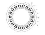
- FIG. 1 is a plan view showing a rotary electric machine according to Embodiment 1 of the present invention.
- a cylindrical stator 2 is held in a cylindrical housing 1.
- the stator 2 includes a laminated iron core 3, a drive coil 4 wound around the laminated iron core 3, and an insulator 5 interposed between the laminated iron core 3 and the drive coil 4.
- a rotor 6 is disposed in the stator 2.
- the rotor 6 is held by the housing 1 so as to be rotatable with respect to the stator 2.
- the rotor 6 has a plurality of permanent magnets 7 fixed to the outer peripheral portion thereof and facing the stator 2.
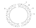
- the laminated core 3 is configured by combining a plurality (two in this example) of arc-shaped divided laminated cores 11 in an annular shape.
- Each of the divided laminated cores 11 is configured by connecting a plurality of (9 in this example) core blocks 12 so as to be rotatable with respect to each other.
- Each core block 12 is configured by laminating a plurality of core pieces 13 in the axial direction of the rotating electrical machine.
- FIG. 5 is an enlarged plan view showing the core piece 13 of FIG.
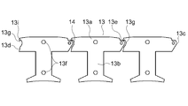
- the core piece 13 includes a back yoke portion 13a that forms an annular yoke portion of the laminated iron core 3, and a magnetic pole teeth portion 13b that projects from the back yoke portion 13a to the inside in the radial direction of the laminated iron core 3 and around which the drive coil 4 is wound. And have.
- the convex part 13c is provided in the 1st end part which is the one end part of the back yoke part 13a in the circumferential direction of the laminated iron core 3. As shown in FIG. Further, a recessed portion 13 d is provided at the second end portion which is the other end portion of the back yoke portion 13 a in the circumferential direction of the laminated core 3. The convex portion 13c is abutted against the concave portion 13d of the core piece 13 adjacent in the circumferential direction.
- the convex portion 13c is provided with a rotating shaft portion 13e protruding in the axial direction of the rotating electrical machine.
- the core blocks 12 are coupled to each other so as to be rotatable about the rotation shaft portion 13e.
- the rotating shaft portion 13e is provided closer to the outer peripheral surface than the inner peripheral surface of the back yoke portion 13a.
- a clearance caulking portion 13f is provided in the center of the back yoke portion 13a and in the vicinity of the tip end portion of the magnetic pole tooth portion 13b.
- the laminated core pieces 13 are fixed to each other by a caulking portion 13f.
- An arc shape is formed at the second end of the back yoke portion 13a so that a gap 14 is formed between the core pieces 13 arranged in an annular shape or an arc shape and the vicinity of the rotation shaft portion 13e of the adjacent convex portion 13c.
- a notch 13g is provided.
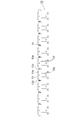
- FIG. 6 is a plan view showing a state in which the divided laminated iron core 11 of FIG. 4 is developed linearly.
- the first end portion and the second end portion of the back yoke portion 13a are formed between the adjacent convex portion 13c and the concave portion 13d in a state where the core piece 13 is linearly expanded so that the magnetic pole teeth portion 13b is parallel to each other.
- a predetermined gap is formed between the outer peripheral side and the inner peripheral side.
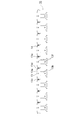
- FIG. 7 is a plan view showing a pressing state of the first core member 15 included in the divided laminated core 11 of FIG. 6, and FIG. 8 is a pressing process of the second core member 16 included in the divided laminated core 11 of FIG.
- FIG. 9 is an enlarged plan view showing a part of the first core member 15 in FIG. 7.
- the first core member 15 formed by sequentially arranging the core pieces 13 in which the convex portions 13c face one side in the rotating direction of the rotating electrical machine, and the convex portions 13c face the other side in the rotating direction of the rotating electric machine.
- the second core members 16 formed by sequentially arranging the core pieces 13 are alternately stacked and connected. As shown in FIGS. 7 and 8, these first and second core members 15 and 16 are manufactured by pressing a magnetic material in a state where the magnetic teeth 13b are linearly expanded so as to be parallel to each other. Is done. Further, in this example, the first and second core members 15 and 16 are alternately stacked in two layers, and are connected in the stacking direction by the caulking portion 13f.
- the dimension of the gap connecting from the outer peripheral side to the inner peripheral side of the back yoke portion 13a is set to the thickness dimension of the core piece 13 (magnetic material) (for example, 0.5 mm). It is preferable to set the degree to above.
- adjacent cores 13 are provided with notches 13g, and in the production state of the divided laminated core 11 linearly developed so that the magnetic pole teeth 13b are parallel, adjacent convex portions Since the gap 14 connected from the outer peripheral side to the inner peripheral side of the back yoke portion 13a is formed between the 13c and the concave portion 13d, it is possible to press the split laminated iron core 11 without using the cutting and bending method. Can be improved, and characteristics such as efficiency and torque pulsation can be improved.
- the core piece 13 can be pressed in a state of being linearly arranged on the electromagnetic steel sheet, the material yield can be improved. Furthermore, since the orientation of the core piece 13 with respect to the electromagnetic steel sheet can be made constant, the influence of the magnetic anisotropy of the electromagnetic steel sheet can be reduced and torque pulsation can be reduced as compared with the case of pressing in an arcuate or annular state. Can be reduced.
- the notch 13g is provided in the recess 13d.
- the same effect can be obtained by providing the notch 13g in the vicinity of the rotation shaft 13e of the protrusion 13c.
- the laminated core 3 is configured by combining the two divided laminated cores 11.
- the laminated core 3 may be configured integrally without being divided, or may be divided into three or more divided laminated cores. 11 combinations may be used.
- FIG. 10 is a plan view showing the main part of the laminated core of the rotating electrical machine according to the second embodiment of the present invention, and corresponds to FIG. 9 of the first embodiment.
- the same or equivalent parts as those in the first embodiment are denoted by the same reference numerals and the description thereof is omitted.
- a flat portion 13h orthogonal to the magnetic pole tooth portion 13b is provided on the outer peripheral surface of the back yoke portion 13a located on the radially outer side of the rotating electrical machine.
- the flat portion 13h of each core piece 13 has the same straight line in a state in which the divided laminated core 11 is linearly expanded so that the magnetic pole teeth 13b are parallel, that is, in the pressed state of the divided laminated core 11 in the first embodiment. It is provided so that it may be located on a line.
- the flat portion 13h is provided in the back yoke portion 13a. Therefore, when the dimension inspection of the divided laminated iron core 11 is performed, the surface formed by the flat portion 13h may be used as the management reference surface. Dimensional inspection can be easily performed, and a highly reliable laminated iron core can be obtained.
- FIG. 11 is a plan view showing the main part of the laminated core of the rotating electrical machine according to Embodiment 3 of the present invention
- FIG. 12 is a plan view showing a state in which the divided laminated core 11 of FIG.
- FIG. 10 is a diagram corresponding to FIG. 5 and FIG. 9 of the first embodiment, respectively.
- the same or equivalent parts as those in the first and second embodiments are denoted by the same reference numerals and the description thereof is omitted.
- a holding projection 13i is provided at the second end of the back yoke portion 13a so as to come into contact with the convex portion 13c when the core block 12 is closed in an annular shape or an arc shape.
- the holding protrusion 13i is provided at the outer peripheral end of the notch 13g. Further, the holding projection 13i is separated from the convex portion 13c when the divided laminated iron core 11 is linearly developed (the gap between the convex portion 13c and the holding projection 13i is very small. 13i appears to be in contact with the convex portion 13c).
- the state when the split laminated core 11 is closed in an annular shape can be maintained, so that the stability of the divided laminated core 11 during material handling is improved and the assembly workability of the rotating electrical machine is improved. be able to.
- FIG. 13 is a plan view showing a state during the manufacture of the laminated core of the rotating electrical machine according to the fourth embodiment of the present invention, and corresponds to FIG. 7 of the first embodiment.
- FIG. 14 is an enlarged plan view showing the main part of FIG. Furthermore, the same reference numerals are used for the same or equivalent parts as in the first, second, and third embodiments, and the description is omitted.
- a width reduction portion 13j having a smaller width dimension than the portion adjacent to the side opposite to the back yoke portion 13a is provided in the vicinity of the connecting portion of the magnetic pole tooth portion 13b to the back yoke portion 13a. That is, the magnetic pole notch portions are provided at both ends in the width direction of the base portion of the magnetic pole tooth portion 13b.
- another magnetic pole tooth portion 13b of the first core member 15 is arranged between the magnetic pole tooth portions 13b of the first core member 15, and two of the divided laminated iron cores 11 can be taken at the time of press working. it can.
- Bs> Bt where Bt is the width dimension of the tip of the magnetic tooth portion 13b and Bs is the width dimension between adjacent width reduction portions 13j.
- Bs ⁇ Bt + 2T
- T the thickness of the core piece 13 (magnetic material).
- two divided laminated iron cores 11 can be taken at the time of press working, and material yield and productivity can be improved.
Landscapes
- Engineering & Computer Science (AREA)
- Power Engineering (AREA)
- Iron Core Of Rotating Electric Machines (AREA)
Abstract
Description
実施の形態1.
図1はこの発明の実施の形態1による回転電機を示す平面図である。図において、円筒状のハウジング1内には、円筒状のステータ2が保持されている。ステータ2は、積層鉄心3と、積層鉄心3に巻回された駆動コイル4と、積層鉄心3と駆動コイル4との間に介在されたインシュレータ5とを有している。
また、実施の形態1では、2個の分割積層鉄心11を組み合わせて積層鉄心3を構成したが、積層鉄心3は分割せずに一体で構成したり、3個以上に分割された分割積層鉄心11の組み合わせで構成したりしてもよい。
次に、図10はこの発明の実施の形態2による回転電機の積層鉄心の要部を示す平面図であり、実施の形態1の図9に対応する図である。また、実施の形態1と同一又は同等部分には同一符号を用いて説明を省略する。
次に、図11はこの発明の実施の形態3による回転電機の積層鉄心の要部を示す平面図、図12は図11の分割積層鉄心11を直線状に展開した状態を示す平面図であり、それぞれ実施の形態1の図5及び図9に対応する図である。また、実施の形態1、2と同一又は同等部分には同一符号を用いて説明を省略する。
次に、図13はこの発明の実施の形態4による回転電機の積層鉄心の製造途中の状態を示す平面図であり、実施の形態1の図7に相当する図である。また、図14は図13の要部を拡大して示す平面図である。さらに、実施の形態1、2、3と同一又は同等部分には同一符号を用いて説明を省略する。
Claims (5)
- バックヨーク部と、上記バックヨーク部から突出した磁極ティース部と、上記バックヨーク部の第1端部に設けられた凸部と、上記バックヨーク部の第2端部に設けられた凹部と、上記凸部に設けられた回転軸部とを有し、円環状に配列され、かつ回転電機の軸方向に積層された複数のコア片を備え、
上記凸部は、周方向に隣接する上記コア片の上記凹部に突き合わされており、
上記凸部が上記回転電機の回転方向の一方を向く上記コア片を順次配列してなる第1のコア部材と、上記凸部が上記回転電機の回転方向の他方を向く上記コア片を順次配列してなる第2のコア部材とが交互に積層連結されており、
上記コア片が積層されてなる複数のコアブロックが上記回転軸部を中心として互いに回転可能に連結されている回転電機の積層鉄心において、
上記回転軸部は、上記バックヨーク部の内周面よりも外周面に近付けて設けられており、
上記バックヨーク部の上記第1及び第2端部の少なくともいずれか一方には、上記コア片を円環状又は円弧状に配列した状態で上記凸部の上記回転軸部近傍と上記凹部との間に隙間ができるように、切欠部が設けられており、
上記バックヨーク部の上記第1端部及び上記第2端部は、上記磁極ティース部が互いに平行になるように上記コア片を直線状に展開した状態で、隣接する上記凸部と上記凹部との間に外周側から内周側に繋がる所定の隙間が生じるように構成されていることを特徴とする回転電機の積層鉄心。 - 上記バックヨーク部の外周側から内周側に繋がる上記隙間の寸法は、上記コア片の厚さ寸法以上であることを特徴とする請求項1記載の回転電機の積層鉄心。
- 上記回転電機の径方向外側に位置する上記バックヨーク部の外周面には、上記磁極ティース部と直交する平坦部が設けられていることを特徴とする請求項1記載の回転電機の積層鉄心。
- 上記バックヨーク部の上記第2端部には、上記コアブロックを円環状又は円弧状に閉じたときに上記凸部に当接する保持突起部が設けられていることを特徴とする請求項1記載の回転電機の積層鉄心。
- 上記磁極ティース部の上記バックヨーク部との連結部近傍には、上記バックヨーク部とは反対側に隣接する部分よりも幅寸法が小さい幅縮小部が設けられていることを特徴とする請求項1記載の積層鉄心。
Priority Applications (6)
| Application Number | Priority Date | Filing Date | Title |
|---|---|---|---|
| CN201080065997.9A CN102823112B (zh) | 2010-04-08 | 2010-04-08 | 旋转电机的层叠铁心 |
| EP10849442.8A EP2557660B1 (en) | 2010-04-08 | 2010-04-08 | Layered iron core of rotary electrical machine |
| KR1020127021325A KR20120116985A (ko) | 2010-04-08 | 2010-04-08 | 회전전기기계의 적층철심 |
| PCT/JP2010/056365 WO2011125199A1 (ja) | 2010-04-08 | 2010-04-08 | 回転電機の積層鉄心 |
| JP2012509243A JP5579832B2 (ja) | 2010-04-08 | 2010-04-08 | 回転電機の積層鉄心 |
| US13/515,963 US9136735B2 (en) | 2010-04-08 | 2010-04-08 | Rotary electric machine laminated core |
Applications Claiming Priority (1)
| Application Number | Priority Date | Filing Date | Title |
|---|---|---|---|
| PCT/JP2010/056365 WO2011125199A1 (ja) | 2010-04-08 | 2010-04-08 | 回転電機の積層鉄心 |
Publications (1)
| Publication Number | Publication Date |
|---|---|
| WO2011125199A1 true WO2011125199A1 (ja) | 2011-10-13 |
Family
ID=44762185
Family Applications (1)
| Application Number | Title | Priority Date | Filing Date |
|---|---|---|---|
| PCT/JP2010/056365 WO2011125199A1 (ja) | 2010-04-08 | 2010-04-08 | 回転電機の積層鉄心 |
Country Status (6)
| Country | Link |
|---|---|
| US (1) | US9136735B2 (ja) |
| EP (1) | EP2557660B1 (ja) |
| JP (1) | JP5579832B2 (ja) |
| KR (1) | KR20120116985A (ja) |
| CN (1) | CN102823112B (ja) |
| WO (1) | WO2011125199A1 (ja) |
Cited By (9)
| Publication number | Priority date | Publication date | Assignee | Title |
|---|---|---|---|---|
| CN103138417A (zh) * | 2011-12-05 | 2013-06-05 | 利莱森玛电机公司 | 分区段的磁路 |
| JP2014075907A (ja) * | 2012-10-04 | 2014-04-24 | Minebea Co Ltd | モータのステータ構造、ブラシレスモータ、およびモータのステータ構造の製造方法 |
| GB2508022A (en) * | 2012-11-20 | 2014-05-21 | Jaguar Land Rover Ltd | Segmented stator arrangement for an electric machine |
| JP2014236597A (ja) * | 2013-06-03 | 2014-12-15 | 三菱電機株式会社 | 分割電機子鉄心の製造装置及び電機子並びにこの電機子を用いた回転電機 |
| WO2015145631A1 (ja) * | 2014-03-26 | 2015-10-01 | 三菱電機株式会社 | 回転電機の電機子鉄心および回転電機 |
| KR20160006785A (ko) | 2013-05-28 | 2016-01-19 | 미쓰비시덴키 가부시키가이샤 | 회전 전기의 철심 |
| CN106233577A (zh) * | 2014-04-16 | 2016-12-14 | 三菱电机株式会社 | 旋转电机的电枢铁芯 |
| CN108110918A (zh) * | 2017-12-29 | 2018-06-01 | 台州市路桥鼎新阳光机电科技有限公司 | 一种电机定子冲片结构及其采用该冲片的定子 |
| US10224767B2 (en) | 2012-11-20 | 2019-03-05 | Jaguar Land Rover Limited | Electric machine and method of operation thereof |
Families Citing this family (9)
| Publication number | Priority date | Publication date | Assignee | Title |
|---|---|---|---|---|
| WO2012160692A1 (ja) * | 2011-05-26 | 2012-11-29 | 三菱電機株式会社 | 永久磁石型モータ |
| CN103703655A (zh) * | 2011-10-06 | 2014-04-02 | 三菱电机株式会社 | 层叠铁心的制造方法以及使用该方法制造的层叠铁心 |
| GB2511353B (en) * | 2013-03-01 | 2015-11-04 | Jaguar Land Rover Ltd | Electric machine having segmented stator with shield elements |
| WO2017033229A1 (ja) * | 2015-08-21 | 2017-03-02 | 三菱電機株式会社 | 永久磁石埋込型モータ、圧縮機、および冷凍空調装置 |
| CN108702042B (zh) * | 2016-02-25 | 2020-10-23 | 株式会社安川电机 | 旋转电机和旋转电机的制造方法 |
| DE112017004402T5 (de) * | 2016-09-02 | 2019-05-16 | Nidec Corporation | Stator, statorherstellungsverfahren und motor |
| CN107707044A (zh) * | 2017-11-21 | 2018-02-16 | 浙江联宜电机有限公司 | 铰链式定子铁芯 |
| DK3745559T3 (en) * | 2019-05-27 | 2022-06-07 | Magnax Bv | Stator til aksialfluxmaskine |
| CN111697717B (zh) * | 2020-06-30 | 2021-06-15 | 珠海凯邦电机制造有限公司 | 电机定子冲片及电机 |
Citations (8)
| Publication number | Priority date | Publication date | Assignee | Title |
|---|---|---|---|---|
| JPH11215744A (ja) * | 1998-01-22 | 1999-08-06 | Matsushita Seiko Co Ltd | ブラシレスモータの固定子 |
| JP2000069693A (ja) * | 1998-08-21 | 2000-03-03 | Matsushita Electric Ind Co Ltd | モータ |
| JP2000201458A (ja) | 1998-06-30 | 2000-07-18 | Mitsubishi Electric Corp | 鉄心装置及びその製造方法 |
| JP2002171725A (ja) | 2000-12-01 | 2002-06-14 | Mitsubishi Electric Corp | 積層コアの製造方法およびその製造に用いる金型装置 |
| JP2004357491A (ja) * | 2003-05-08 | 2004-12-16 | Asmo Co Ltd | 回転電機のステータ及びその製造方法 |
| JP2006271091A (ja) * | 2005-03-23 | 2006-10-05 | Asmo Co Ltd | ブラシレスモータのステータ及びブラシレスモータ |
| JP2006304460A (ja) * | 2005-04-19 | 2006-11-02 | Mitsubishi Electric Corp | 回転電機の固定子 |
| JP2009254086A (ja) * | 2008-04-04 | 2009-10-29 | Mitsubishi Electric Corp | 分割固定子鉄心の製造方法及び電動機 |
Family Cites Families (17)
| Publication number | Priority date | Publication date | Assignee | Title |
|---|---|---|---|---|
| US4990809A (en) * | 1987-04-27 | 1991-02-05 | The Superior Electric Company | Variable reluctance motor |
| JP3430521B2 (ja) * | 1992-09-24 | 2003-07-28 | 松下電器産業株式会社 | 回転電機の固定子 |
| JP3568364B2 (ja) * | 1996-09-30 | 2004-09-22 | 松下電器産業株式会社 | 回転電機のコア |
| JP3609649B2 (ja) * | 1999-06-29 | 2005-01-12 | 三洋電機株式会社 | ブラシレスdcモータ及びこのモータを用いた冷媒圧縮機 |
| JP3623702B2 (ja) * | 1999-09-28 | 2005-02-23 | 山洋電気株式会社 | 回転電機用ステータ |
| JP4747423B2 (ja) * | 2001-03-02 | 2011-08-17 | パナソニック株式会社 | 電動機 |
| JP3786854B2 (ja) * | 2001-08-30 | 2006-06-14 | 株式会社三井ハイテック | 積層鉄心の製造方法 |
| US7111380B2 (en) * | 2002-10-31 | 2006-09-26 | Emerson Electric Co. | Method for forming an annular stator assembly |
| JP4057449B2 (ja) * | 2003-03-10 | 2008-03-05 | アスモ株式会社 | 回転電機のコア |
| US6946769B2 (en) * | 2003-05-08 | 2005-09-20 | Asmo Co., Ltd. | Insulator and manufacturing method thereof, and stator for electric rotating machine |
| US7122933B2 (en) * | 2004-05-19 | 2006-10-17 | Emerson Electric Co. | Reduced coil segmented stator |
| JP2006081278A (ja) * | 2004-09-08 | 2006-03-23 | Asmo Co Ltd | ブラシレスモータ |
| US7348706B2 (en) * | 2005-10-31 | 2008-03-25 | A. O. Smith Corporation | Stator assembly for an electric machine and method of manufacturing the same |
| JP4835168B2 (ja) * | 2006-01-25 | 2011-12-14 | 日本電産株式会社 | 電機子のコア、電機子、モータ、記録ディスク駆動装置およびコアプレートの製造方法 |
| JP5094257B2 (ja) | 2007-07-25 | 2012-12-12 | 三菱電機株式会社 | 回転電機の鉄心 |
| JP5171224B2 (ja) * | 2007-11-22 | 2013-03-27 | 三菱電機株式会社 | 回転電機 |
| JP5251384B2 (ja) * | 2008-09-16 | 2013-07-31 | 三菱電機株式会社 | 積層コアおよびその製造方法 |
-
2010
- 2010-04-08 CN CN201080065997.9A patent/CN102823112B/zh active Active
- 2010-04-08 KR KR1020127021325A patent/KR20120116985A/ko active Search and Examination
- 2010-04-08 US US13/515,963 patent/US9136735B2/en active Active
- 2010-04-08 EP EP10849442.8A patent/EP2557660B1/en active Active
- 2010-04-08 JP JP2012509243A patent/JP5579832B2/ja active Active
- 2010-04-08 WO PCT/JP2010/056365 patent/WO2011125199A1/ja active Application Filing
Patent Citations (8)
| Publication number | Priority date | Publication date | Assignee | Title |
|---|---|---|---|---|
| JPH11215744A (ja) * | 1998-01-22 | 1999-08-06 | Matsushita Seiko Co Ltd | ブラシレスモータの固定子 |
| JP2000201458A (ja) | 1998-06-30 | 2000-07-18 | Mitsubishi Electric Corp | 鉄心装置及びその製造方法 |
| JP2000069693A (ja) * | 1998-08-21 | 2000-03-03 | Matsushita Electric Ind Co Ltd | モータ |
| JP2002171725A (ja) | 2000-12-01 | 2002-06-14 | Mitsubishi Electric Corp | 積層コアの製造方法およびその製造に用いる金型装置 |
| JP2004357491A (ja) * | 2003-05-08 | 2004-12-16 | Asmo Co Ltd | 回転電機のステータ及びその製造方法 |
| JP2006271091A (ja) * | 2005-03-23 | 2006-10-05 | Asmo Co Ltd | ブラシレスモータのステータ及びブラシレスモータ |
| JP2006304460A (ja) * | 2005-04-19 | 2006-11-02 | Mitsubishi Electric Corp | 回転電機の固定子 |
| JP2009254086A (ja) * | 2008-04-04 | 2009-10-29 | Mitsubishi Electric Corp | 分割固定子鉄心の製造方法及び電動機 |
Cited By (18)
| Publication number | Priority date | Publication date | Assignee | Title |
|---|---|---|---|---|
| FR2983656A1 (fr) * | 2011-12-05 | 2013-06-07 | Leroy Somer Moteurs | Circuit magnetique en secteurs |
| WO2013104959A1 (fr) * | 2011-12-05 | 2013-07-18 | Moteurs Leroy-Somer | Circuit magnetique en secteurs |
| US20140361657A1 (en) * | 2011-12-05 | 2014-12-11 | Moteurs Leroy-Somer | Magnetic circuit comprising sectors |
| CN103138417A (zh) * | 2011-12-05 | 2013-06-05 | 利莱森玛电机公司 | 分区段的磁路 |
| JP2014075907A (ja) * | 2012-10-04 | 2014-04-24 | Minebea Co Ltd | モータのステータ構造、ブラシレスモータ、およびモータのステータ構造の製造方法 |
| GB2508022A (en) * | 2012-11-20 | 2014-05-21 | Jaguar Land Rover Ltd | Segmented stator arrangement for an electric machine |
| GB2508022B (en) * | 2012-11-20 | 2015-07-15 | Jaguar Land Rover Ltd | Electric machine and method of operation thereof |
| US10224767B2 (en) | 2012-11-20 | 2019-03-05 | Jaguar Land Rover Limited | Electric machine and method of operation thereof |
| US9960644B2 (en) | 2013-05-28 | 2018-05-01 | Mitsubishi Electric Corporation | Core for rotary electric machine |
| KR20160006785A (ko) | 2013-05-28 | 2016-01-19 | 미쓰비시덴키 가부시키가이샤 | 회전 전기의 철심 |
| JP2014236597A (ja) * | 2013-06-03 | 2014-12-15 | 三菱電機株式会社 | 分割電機子鉄心の製造装置及び電機子並びにこの電機子を用いた回転電機 |
| WO2015145631A1 (ja) * | 2014-03-26 | 2015-10-01 | 三菱電機株式会社 | 回転電機の電機子鉄心および回転電機 |
| JPWO2015145631A1 (ja) * | 2014-03-26 | 2017-04-13 | 三菱電機株式会社 | 回転電機の電機子鉄心および回転電機 |
| US10199887B2 (en) | 2014-03-26 | 2019-02-05 | Mitsubishi Electric Corporation | Rotary electric machine armature core and rotary electric machine |
| JPWO2015159389A1 (ja) * | 2014-04-16 | 2017-04-13 | 三菱電機株式会社 | 回転電機の電機子鉄心 |
| US10128700B2 (en) | 2014-04-16 | 2018-11-13 | Mitsubishi Electric Corporation | Rotary electric machine armature core |
| CN106233577A (zh) * | 2014-04-16 | 2016-12-14 | 三菱电机株式会社 | 旋转电机的电枢铁芯 |
| CN108110918A (zh) * | 2017-12-29 | 2018-06-01 | 台州市路桥鼎新阳光机电科技有限公司 | 一种电机定子冲片结构及其采用该冲片的定子 |
Also Published As
| Publication number | Publication date |
|---|---|
| US9136735B2 (en) | 2015-09-15 |
| EP2557660A1 (en) | 2013-02-13 |
| JP5579832B2 (ja) | 2014-08-27 |
| KR20120116985A (ko) | 2012-10-23 |
| EP2557660A4 (en) | 2016-12-07 |
| JPWO2011125199A1 (ja) | 2013-07-08 |
| CN102823112A (zh) | 2012-12-12 |
| US20120248928A1 (en) | 2012-10-04 |
| EP2557660B1 (en) | 2019-03-06 |
| CN102823112B (zh) | 2015-07-29 |
Similar Documents
| Publication | Publication Date | Title |
|---|---|---|
| JP5579832B2 (ja) | 回転電機の積層鉄心 | |
| JP5511956B2 (ja) | 回転電機の積層鉄心 | |
| TWI451666B (zh) | 積層鐵心之製造方法及以該方法所製造之積層鐵心 | |
| JP5603437B2 (ja) | 回転電機の積層鉄心及びその製造方法 | |
| JP6444497B2 (ja) | 回転電機およびその製造方法 | |
| JP2011151884A (ja) | 回転電機および回転電機の固定子の製造方法 | |
| JP2011030320A (ja) | 回転電機及び回転電機の製造方法 | |
| JPWO2017195249A1 (ja) | 固定子鉄心、及びその固定子鉄心を備えた電動機 | |
| JP2012151970A (ja) | 磁石埋込型ロータ、及びモータ | |
| JP6045638B2 (ja) | 積層鉄心の製造方法 | |
| JP4794650B2 (ja) | 回転電機 | |
| JP2019022425A (ja) | ステータコア、ステータコアの製造装置、ステータコアの製造方法、電動機および送風機 | |
| JP2017175774A (ja) | 回転電機、および分割ステータ鋼板の製造方法 | |
| JP5311290B2 (ja) | アキシャルギャップ型回転電機用ステータコアの製造方法 | |
| WO2022137621A1 (ja) | 分割コア、回転電機、分割コアの製造方法、および、回転電機の製造方法 | |
| JP2019176560A (ja) | ステータコア及びモータ | |
| JP2019180214A (ja) | モータ | |
| JP2005095000A (ja) | 内転型電動機の固定子 | |
| WO2022172938A1 (ja) | モータのコアブロック及びモータのコアブロックの製造方法 | |
| JPWO2013051125A1 (ja) | 積層鉄心の製造方法およびそれにより製造された積層鉄心 | |
| JP2004336997A (ja) | 内転型電動機の固定子 | |
| JP2018125986A (ja) | 回転電機のステータ |
Legal Events
| Date | Code | Title | Description |
|---|---|---|---|
| WWE | Wipo information: entry into national phase |
Ref document number: 201080065997.9 Country of ref document: CN |
|
| 121 | Ep: the epo has been informed by wipo that ep was designated in this application |
Ref document number: 10849442 Country of ref document: EP Kind code of ref document: A1 |
|
| WWE | Wipo information: entry into national phase |
Ref document number: 2012509243 Country of ref document: JP |
|
| WWE | Wipo information: entry into national phase |
Ref document number: 13515963 Country of ref document: US |
|
| WWE | Wipo information: entry into national phase |
Ref document number: 2010849442 Country of ref document: EP |
|
| ENP | Entry into the national phase |
Ref document number: 20127021325 Country of ref document: KR Kind code of ref document: A |
|
| NENP | Non-entry into the national phase |
Ref country code: DE |