WO2019216351A1 - 遠心クラッチ - Google Patents
遠心クラッチ Download PDFInfo
- Publication number
- WO2019216351A1 WO2019216351A1 PCT/JP2019/018431 JP2019018431W WO2019216351A1 WO 2019216351 A1 WO2019216351 A1 WO 2019216351A1 JP 2019018431 W JP2019018431 W JP 2019018431W WO 2019216351 A1 WO2019216351 A1 WO 2019216351A1
- Authority
- WO
- WIPO (PCT)
- Prior art keywords
- clutch
- weight
- cam body
- plate
- side cam
- Prior art date
Links
Images


Classifications
-
- F—MECHANICAL ENGINEERING; LIGHTING; HEATING; WEAPONS; BLASTING
- F16—ENGINEERING ELEMENTS AND UNITS; GENERAL MEASURES FOR PRODUCING AND MAINTAINING EFFECTIVE FUNCTIONING OF MACHINES OR INSTALLATIONS; THERMAL INSULATION IN GENERAL
- F16D—COUPLINGS FOR TRANSMITTING ROTATION; CLUTCHES; BRAKES
- F16D43/00—Automatic clutches
- F16D43/02—Automatic clutches actuated entirely mechanically
- F16D43/20—Automatic clutches actuated entirely mechanically controlled by torque, e.g. overload-release clutches, slip-clutches with means by which torque varies the clutching pressure
- F16D43/21—Automatic clutches actuated entirely mechanically controlled by torque, e.g. overload-release clutches, slip-clutches with means by which torque varies the clutching pressure with friction members
- F16D43/211—Automatic clutches actuated entirely mechanically controlled by torque, e.g. overload-release clutches, slip-clutches with means by which torque varies the clutching pressure with friction members with radially applied torque-limiting friction surfaces
-
- F—MECHANICAL ENGINEERING; LIGHTING; HEATING; WEAPONS; BLASTING
- F16—ENGINEERING ELEMENTS AND UNITS; GENERAL MEASURES FOR PRODUCING AND MAINTAINING EFFECTIVE FUNCTIONING OF MACHINES OR INSTALLATIONS; THERMAL INSULATION IN GENERAL
- F16D—COUPLINGS FOR TRANSMITTING ROTATION; CLUTCHES; BRAKES
- F16D43/00—Automatic clutches
- F16D43/02—Automatic clutches actuated entirely mechanically
- F16D43/04—Automatic clutches actuated entirely mechanically controlled by angular speed
- F16D43/14—Automatic clutches actuated entirely mechanically controlled by angular speed with centrifugal masses actuating the clutching members directly in a direction which has at least a radial component; with centrifugal masses themselves being the clutching members
- F16D43/18—Automatic clutches actuated entirely mechanically controlled by angular speed with centrifugal masses actuating the clutching members directly in a direction which has at least a radial component; with centrifugal masses themselves being the clutching members with friction clutching members
-
- F—MECHANICAL ENGINEERING; LIGHTING; HEATING; WEAPONS; BLASTING
- F16—ENGINEERING ELEMENTS AND UNITS; GENERAL MEASURES FOR PRODUCING AND MAINTAINING EFFECTIVE FUNCTIONING OF MACHINES OR INSTALLATIONS; THERMAL INSULATION IN GENERAL
- F16D—COUPLINGS FOR TRANSMITTING ROTATION; CLUTCHES; BRAKES
- F16D43/00—Automatic clutches
- F16D43/02—Automatic clutches actuated entirely mechanically
- F16D43/04—Automatic clutches actuated entirely mechanically controlled by angular speed
- F16D43/14—Automatic clutches actuated entirely mechanically controlled by angular speed with centrifugal masses actuating the clutching members directly in a direction which has at least a radial component; with centrifugal masses themselves being the clutching members
- F16D2043/145—Automatic clutches actuated entirely mechanically controlled by angular speed with centrifugal masses actuating the clutching members directly in a direction which has at least a radial component; with centrifugal masses themselves being the clutching members the centrifugal masses being pivoting
-
- F—MECHANICAL ENGINEERING; LIGHTING; HEATING; WEAPONS; BLASTING
- F16—ENGINEERING ELEMENTS AND UNITS; GENERAL MEASURES FOR PRODUCING AND MAINTAINING EFFECTIVE FUNCTIONING OF MACHINES OR INSTALLATIONS; THERMAL INSULATION IN GENERAL
- F16H—GEARING
- F16H9/00—Gearings for conveying rotary motion with variable gear ratio, or for reversing rotary motion, by endless flexible members
- F16H9/02—Gearings for conveying rotary motion with variable gear ratio, or for reversing rotary motion, by endless flexible members without members having orbital motion
- F16H9/04—Gearings for conveying rotary motion with variable gear ratio, or for reversing rotary motion, by endless flexible members without members having orbital motion using belts, V-belts, or ropes
- F16H9/12—Gearings for conveying rotary motion with variable gear ratio, or for reversing rotary motion, by endless flexible members without members having orbital motion using belts, V-belts, or ropes engaging a pulley built-up out of relatively axially-adjustable parts in which the belt engages the opposite flanges of the pulley directly without interposed belt-supporting members
- F16H9/16—Gearings for conveying rotary motion with variable gear ratio, or for reversing rotary motion, by endless flexible members without members having orbital motion using belts, V-belts, or ropes engaging a pulley built-up out of relatively axially-adjustable parts in which the belt engages the opposite flanges of the pulley directly without interposed belt-supporting members using two pulleys, both built-up out of adjustable conical parts
- F16H9/18—Gearings for conveying rotary motion with variable gear ratio, or for reversing rotary motion, by endless flexible members without members having orbital motion using belts, V-belts, or ropes engaging a pulley built-up out of relatively axially-adjustable parts in which the belt engages the opposite flanges of the pulley directly without interposed belt-supporting members using two pulleys, both built-up out of adjustable conical parts only one flange of each pulley being adjustable
Definitions
- the present invention relates to a centrifugal clutch that blocks transmission of rotational driving force to the driven side until the engine reaches a predetermined rotational speed and transmits rotational driving force to the driven side when the engine reaches a predetermined rotational speed.
- centrifugal clutches that transmit rotational driving force to the driven side when the engine reaches a predetermined rotational speed are used.
- a drive plate that is rotationally driven by a rotational driving force from an engine, and is rotatably supported by the drive plate, and is opened radially outward by the drive of the drive plate and pressed against the outer clutch.
- a centrifugal clutch with a clutch weight is disclosed.
- the centrifugal clutch is provided with a protrusion and a driven part constituting a pair of cams between the drive plate and the clutch weight, and the pair of cams quickly and strongly presses the clutch weight against the clutch outer. It is configured to be able to.
- the cam angle is an angle between a normal line to a straight line passing through the sliding portion where the protrusion and the driven portion are in contact with each other and the rotational driving center of the drive plate and the sliding direction line in the sliding portion. .
- the sliding direction line is a tangent line of the curved surface at the sliding portion when at least one of the protrusion and the driven portion is a curved surface.
- the present invention has been made to cope with the above-described problems, and an object of the present invention is to provide a centrifugal clutch capable of maintaining the assist thrust constant or reducing the assist thrust even when the clutch shoe is worn.
- the present invention is characterized in that a drive plate that rotates integrally with a driven pulley under the driving force of an engine, and a cylindrical surface provided concentrically with the drive plate on the outside of the drive plate.
- a clutch outer having a clutch shoe formed extending along the circumferential direction of the drive plate and facing the cylindrical surface of the clutch outer, and having one end side in the circumferential direction on the drive plate
- a clutch weight that is rotatably mounted through a pin sliding hole and the other end is displaced toward the outer cylindrical surface of the clutch outer surface, and the drive plate has a surface that extends in the direction of the rotational drive shaft of the drive plate. Plate-side cam body and the other of the clutch weight provided on the clutch weight.
- a weight-side cam body that slides on the plate-side cam body when the end-side displacement is caused, and the swing support pin is provided on one of the drive plate and the clutch weight
- the pin sliding hole is formed in the other of the drive plate and the clutch weight, and the rotational drive direction of the drive plate on the one end side of the clutch weight.
- the rocking support pin is slidably fitted so that it can slide and displace, and at least one of the sliding surfaces of the plate-side cam body and the weight-side cam body has a sliding surface.
- the drive plate is configured with a curved surface, and the sliding surface includes a sliding portion where the plate side cam body and the weight side cam body are in contact with each other.
- the clutch shoe contacts the cylindrical surface of the clutch outer before and after the wear of the clutch shoe progresses
- the cam angles are the same, or the cam angle is larger when the wear progresses.
- the centrifugal clutch is configured such that at least one of the sliding surfaces of the plate-side cam body provided on the drive plate and the weight-side cam body provided on the clutch weight is a curved surface.
- the sliding surface is formed into a curved surface with the same cam angle or a curved surface with the same cam angle when the clutch shoe contacts the cylindrical surface of the clutch outer before and after the wear of the clutch shoe proceeds. ing.
- the assist thrust can be kept constant even when the clutch shoe is worn, and the feeling of driving operation can be kept constant, and the increase of the assist thrust is suppressed.
- the increase in the surface pressure between the plate-side cam body and the weight-side cam body and the surface pressure between the clutch shoe and the clutch outer can be suppressed to suppress wear and damage of the friction portion.
- the long hole in each above-mentioned invention is a through-hole or a blind hole whose length in one direction is long and elongated as a whole with respect to the width direction orthogonal to the one direction.
- the plate-side cam body and the weight-side cam body are configured such that the at least one sliding surface is a cylindrical surface of the clutch outer before and after the wear of the clutch shoe proceeds.
- the cam angles are the same when they come into contact with each other.
- the centrifugal clutch is configured so that the at least one sliding surface of the plate side cam body and the weight side cam body is before and after the wear of the clutch shoe proceeds. Since the cam angle when contacting the outer cylindrical surface is the same, it is possible to keep the assist thrust constant even when the clutch shoe wears, and to make the feeling of driving operation constant. At the same time, it is possible to prevent the frictional members such as the plate side cam body, the weight side cam body, the clutch shoe, and the clutch outer from being worn quickly.
- the plate-side cam body is configured with a curved surface having a convex sliding surface
- the weight-side cam body has a convex sliding surface. And having a concave or convex curved surface that slides relative to the curved surface.
- the centrifugal clutch is configured such that the sliding surface of the plate side cam body has a convex curved surface, and the sliding surface of the weight side cam body. Is configured to have a concave or convex curved surface that slides with respect to the convex curved surface, and both sliding surfaces are configured with curved surfaces, and therefore, of the plate side cam body and the weight side cam body. Compared with the case where one is formed in a planar shape extending linearly, the plate-side cam body and the weight-side cam body can be physically made smaller, and the centrifugal clutch can be made compact.
- the plate-side cam body is constituted by a roller that is rotatably supported by the drive plate, and the weight-side cam body has a sliding surface that is a roller. It is in having a curved surface that slides relative to.
- the centrifugal clutch is configured by a roller in which the plate-side cam body is rotatably supported with respect to the drive plate, and sliding on the weight-side cam body. Since the surface has a curved surface that slides relative to the roller, the plate-side cam body and the weight-side cam body can be made physically small and simple.
- centrifugal clutch further includes a fulcrum side sliding member that is provided between the swing support pin and the pin sliding hole and slides both.
- the centrifugal clutch includes the swing support pin and the pin sliding because the swing support pin and the pin sliding hole slide through the fulcrum side sliding member.
- the slidability between the hole and the fulcrum side sliding member is improved, the clutch weight can be rotated and displaced more smoothly with respect to the clutch outer, and wear of the swing support pin and the pin sliding hole is prevented. can do.
- the centrifugal clutch is configured such that the swing support pin and the pin sliding hole are each made of a metal material, and the fulcrum side slide member is made of a resin material, so that the swing support pin and the pin slide hole are connected to the fulcrum side. The slidability with the sliding member can be further improved.
- thermoplastic resin or a thermosetting resin having heat resistance and wear resistance can be used, and engineering plastic or super engineering plastic is suitable.
- PEEK polyether ether ketone resin
- PPS polyphenylene sulfide resin
- PAI polyamideimide resin
- PTFE fluororesin
- PI polyimide resin
- thermosetting resin diallyl phthalate resin (PDAP), epoxy resin (EP) or silicon resin (SI) can be used.
- FIG. 2 is a side view of the centrifugal clutch as viewed from line 2-2 shown in FIG. It is a perspective view which shows roughly the external appearance structure of the drive plate in the centrifugal clutch shown in FIG. 1 and FIG. 2, respectively.
- FIG. 3 is a partially exploded perspective view for illustrating an assembled state of a drive plate, a fulcrum side sliding member, a plate side cam body, and a clutch weight in the centrifugal clutch shown in FIGS. 1 and 2, respectively.
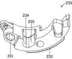
- FIG. 3 is a perspective view showing an outline of an external configuration of a clutch weight in the centrifugal clutch shown in FIGS.
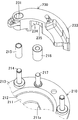
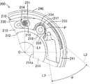
- FIG. 3 is a partially enlarged view showing the centrifugal clutch shown in FIG. 2 in a disconnected state where the clutch shoe does not contact the outer clutch.
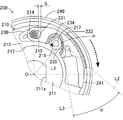
- FIG. 7 is a partially enlarged view showing a connected state in which the clutch shoe in the centrifugal clutch shown in FIG. 6 is pressed against the outer clutch in an initial state with little or no wear.
- FIG. 8 is a partially enlarged view showing a state immediately before the clutch weight in the centrifugal clutch shown in FIG. 7 is tilted radially inward of the drive plate.
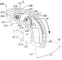
- FIG. 7 is a partially enlarged view showing a connected state in which the clutch shoe in the centrifugal clutch shown in FIG.
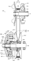
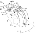
- FIG. 1 is a plan sectional view schematically showing a configuration of a power transmission mechanism 100 including a centrifugal clutch 200 according to the present invention.
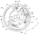
- FIG. 2 is a side view of the centrifugal clutch 200 as viewed from line 2-2 shown in FIG.
- the power transmission mechanism 100 including the centrifugal clutch 200 is provided between an engine and a rear wheel that is a driving wheel in a motorcycle such as a scooter, and automatically changes a reduction ratio with respect to the engine speed. It is a mechanical device that transmits or blocks the rotational driving force to the rear wheels.
- the power transmission mechanism 100 mainly includes a transmission 101 and a centrifugal clutch 200, respectively.
- the transmission 101 is a mechanical device that continuously reduces a rotational driving force from an engine (not shown) and transmits the rotational driving force to the centrifugal clutch 200, and mainly includes a drive pulley 110, a V belt 120, and a driven pulley 130, respectively.
- the drive pulley 110 is a mechanical device that is provided on a crankshaft 111 extending from the engine and is directly driven to rotate by the rotational driving force of the engine.
- the drive pulley 110 mainly includes a fixed drive plate 112 and a movable drive plate 113. It is configured.
- the fixed drive plate 112 is a component that is rotationally driven while being held with the V-belt 120 sandwiched with the movable drive plate 113, and is configured by forming a metal material into a conical cylinder shape.
- the fixed drive plate 112 is fixedly mounted on the crankshaft 111 with its convex surface facing the movable drive plate 113 (engine side). That is, the fixed drive plate 112 is always driven to rotate integrally with the crankshaft 111. Further, on the concave surface of the fixed drive plate 112, a plurality of radiating fins 112 a are provided radially about the axis of the crankshaft 111.
- the movable drive plate 113 is a component that is rotationally driven in a state where the V belt 120 is held together with the fixed drive plate 112, and is configured by forming a metal material into a conical cylinder shape.
- the movable drive plate 113 is attached to the crankshaft 111 such that the convex surface faces the fixed drive plate 112.
- the movable drive plate 113 is attached via an impregnated bush on a sleeve bearing 114 that is fixedly fitted to the crankshaft 111, and slides in the axial direction and the circumferential direction with respect to the sleeve bearing 114, respectively. It is attached movably.
- a plurality of roller weights 115 are provided on the concave surface of the movable drive plate 113 while being pressed by the ramp plate 116.
- the roller weight 115 is a component for pressing the movable drive plate 113 toward the fixed drive plate 112 in cooperation with the ramp plate 116 by being displaced radially outward in accordance with an increase in the rotational speed of the movable drive plate 113. Yes, it is formed by forming a metal material into a cylindrical shape.
- the ramp plate 116 is a component that presses the roller weight 115 toward the movable drive plate 113, and is configured by bending a metal plate toward the movable drive plate 113.
- the V-belt 120 is a component for transmitting the rotational driving force of the drive pulley 110 to the driven pulley 130, and is formed in an endless ring shape whose core wire is covered with an elastic material such as a rubber material.
- the V-belt 120 is disposed between the fixed drive plate 112 and the movable drive plate 113 and between the fixed driven plate 131 and the movable driven plate 134 in the driven pulley 130 and between the drive pulley 110 and the driven pulley 130. It is erected.
- the driven pulley 130 is a mechanical device that is rotationally driven by the rotational driving force from the engine transmitted through the drive pulley 110 and the V-belt 120, respectively.
- the driven pulley 130 mainly includes a fixed driven plate 131 and a movable driven plate 134, respectively. Has been.
- the fixed driven plate 131 is a component that is rotationally driven while being held with the V-belt 120 sandwiched with the movable driven plate 134, and is configured by forming a metal material into a conical cylinder shape.
- the fixed driven plate 131 is fixedly mounted on the driven sleeve 132 with the convex surface facing the movable driven plate 134.
- the driven sleeve 132 is a metallic cylindrical part that is rotationally driven integrally with the fixed driven plate 131, and is attached to the drive shaft 133 via a bearing so as to be relatively rotatable.
- the drive shaft 133 is a metal rotating shaft for driving the rear wheel of the motorcycle on which the power transmission mechanism 100 is mounted via a transmission (not shown). In this case, the rear wheel of the motorcycle is attached to one end (right side in the figure) of the drive shaft 133.
- the movable driven plate 134 is a component that is rotationally driven while being held with the V-belt 120 sandwiched with the fixed driven plate 131, and is configured by forming a metal material into a conical cylinder shape.
- the movable driven plate 134 is fitted in the axially slidable state with respect to the driven sleeve 132 such that the convex surface faces the fixed driven plate 131.
- a torque spring 135 is provided on the concave surface of the movable driven plate 134 between the drive plate 210 and the centrifugal clutch 200.
- the torque spring 135 is a coil spring that elastically presses the movable driven plate 134 toward the fixed driven plate 131 side. That is, the transmission 101 has a V-belt defined by a diameter sandwiching the V-belt 120 defined by the interval between the fixed drive plate 112 and the movable drive plate 113, and an interval between the fixed driven plate 131 and the movable driven plate 134.
- the engine speed is changed steplessly according to the magnitude relationship with the diameter across 120.
- Centrifugal clutch 200 is provided on each of the leading end sides of driven sleeve 132 and drive shaft 133.
- Centrifugal clutch 200 is a mechanical device that transmits or interrupts the rotational driving force of the engine transmitted through transmission 101 to drive shaft 133, and mainly includes drive plate 210, three clutch weights 230, and clutch outer 240, respectively. It is prepared for.
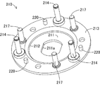
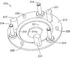
- the drive plate 210 is a component that is rotationally driven integrally with the driven sleeve 132, and is formed by forming a metal material into a stepped disk shape. More specifically, as shown in FIGS. 3 and 4, the drive plate 210 has a through hole 211 a through which the driven sleeve 132 passes at the center of the flat bottom portion 211, and the bottom portion 211. A flange portion 213 projecting in a flange shape is formed at the distal end portion of the cylindrical portion 212 that stands up around the periphery. The flange portion 213 is provided with three swing support pins 214, cam body support pins 217, and damper receiving pins 220 at equal intervals, respectively, along the circumferential direction.
- the swing support pin 214 is a part for pivotally supporting one end side of a clutch weight 230, which will be described later, and swinging the other end side.
- the swing support pin 214 is a metal stepped rod. It is configured. In this case, the swing support pin 214 is fixedly attached to the flange portion 213 by the attachment bolt 214a.
- the swinging support pin 214 has an E-ring 214b attached to a tip portion thereof and an E-ring 214b attached to the distal end in a state of passing through the pin sliding hole 231 of the clutch weight 230 via a fulcrum-side sliding member 215 on the outer peripheral portion.
- the clutch weight 230 is supported while being sandwiched between the clutch weight 230 and the side plate 216.
- the fulcrum-side sliding member 215 is a part that is disposed between the swing support pin 214 and the pin sliding hole 231 and improves the slidability of both, and is configured by forming a resin material in a cylindrical shape.
- the fulcrum side sliding member 215 is capable of rotating and sliding with respect to the swing support pin 214 and the pin slide hole 231, that is, with respect to the swing support pin 214 and the pin slide hole 231.
- Each is formed with a dimensional tolerance that is a gap fit.
- thermoplastic resin or a thermosetting resin having heat resistance and wear resistance can be used, and engineering plastic or super engineering plastic is preferable.
- polyether ether ketone resin (PEEK), polyphenylene sulfide resin (PPS), polyamideimide resin (PAI), fluororesin (PTFE) or polyimide resin (PI) can be used as the thermoplastic resin.
- thermosetting resin diallyl phthalate resin (PDAP), epoxy resin (EP) or silicon resin (SI) can be used.
- the side plate 216 is a part for preventing the three clutch weights 230 from being detached from the swing support pins 214, and is configured by forming a metal material in a ring shape.
- the cam body support pin 217 is a part for supporting the plate-side cam body 218 in a rotatable state, and is composed of a metal stepped rod.
- the cam body support pin 217 is fixedly attached by a mounting bolt 217 a on a flange portion 213 that faces the portion of the clutch weight 230 that is closer to the distal end portion than the pin sliding hole 231 in the clutch weight 230.
- the plate-side cam body 218 is a part for pressing the clutch weight 230 toward the clutch outer 240 side, and is configured by forming a resin material into a cylindrical shape.
- the plate-side cam body 218 is formed with an inner diameter capable of rotating and sliding with respect to the cam body support pin 217, that is, with a dimensional tolerance that is a so-called clearance fit with respect to the cam body support pin 217.
- the resin material constituting the plate side cam body 218 is the same as the resin material constituting the fulcrum side sliding member 215.
- the damper receiving pin 220 is a part for supporting the damper 221 and is composed of a metal rod.
- the damper 221 is a component that guides a swinging motion that causes the other end portion of the clutch weight 230 to approach or separate from the clutch outer 240 and serves as a cushioning material at the time of separation, and the rubber material is formed in a cylindrical shape. Configured.
- the damper 221 is fixedly fitted on the outer peripheral surface of the damper receiving pin 220.
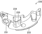
- the three clutch weights 230 are rotated from the engine by contacting or separating the clutch outer 240 via the clutch shoe 233 according to the rotational speed of the drive plate 210. It is a part for transmitting or interrupting the driving force to the drive shaft 133, and is configured by forming a metal material (for example, zinc material) into a curved shape extending along the circumferential direction of the drive plate 210.
- a metal material for example, zinc material
- Each of the clutch weights 230 has one end side rotatably supported by a swing support pin 214 and a fulcrum side sliding member 215 via a pin sliding hole 231, and the other end side of each clutch weight 230. It is connected to the adjacent clutch weight 230 by a connection spring 232 and pulled toward the inner side of the drive plate 210. That is, the clutch weight 230 includes the swing support pin 214, the fulcrum side sliding member 215, and the fulcrum side sliding member 215 on the drive plate 210 in a state where the other end provided with the clutch shoe 233 is swingable with respect to the clutch outer 240. Each pin is supported through a sliding hole 231.
- the pin sliding hole 231 is a portion that is pivotably and slidably fitted to the swing support pin 214 of the drive plate 210 via a fulcrum side sliding member 215, and in the thickness direction of the clutch weight 230. It is comprised by the through-hole which penetrates.
- the pin sliding hole 231 is formed in a long hole shape so that the one end side of the clutch weight 230 is displaced rearward in the rotational driving direction of the drive plate 210 when the clutch shoe 233 comes into contact with the clutch outer 240. Has been.
- the long holes constituting the pin sliding holes 231 are formed so that the length in one direction is long and elongated as a whole in the width direction perpendicular to the one direction. More specifically, the pin sliding hole 231 is formed with an inner diameter that is slightly larger than the outer diameter of the fulcrum side sliding member 215 in the width direction that is the radial direction of the drive plate 210. .
- the longitudinal direction of the pin sliding hole 231 allows the displacement of the clutch weight 230 to the side where the pressing of the weight side cam body 235 of the clutch weight 230 against the plate side cam body 218 is strengthened and the riding is further promoted. It is formed in a circular arc shape or a linear shape extending in the direction.
- the pin sliding hole 231 is formed to extend in an arc shape on the front side of the drive plate 210 in the rotational driving direction.
- the two arcs constituting the longitudinal direction of the pin sliding hole 231 are concentric with the drive plate 210 in this embodiment, but are not necessarily concentric.
- the clutch shoe 233 is a component for increasing the frictional force with respect to the inner peripheral surface of the clutch outer 240, and is configured by forming a friction material in a plate shape extending in an arc shape.
- the clutch shoe 233 is provided on the outer peripheral surface of each clutch weight 230 on the tip side opposite to the pin sliding hole 231.
- the plate-side cam body escape portion 234 is formed in a concave shape so as to cover the plate-side cam body 218 at a portion of each inner circumferential surface of each clutch weight 230 facing the plate-side cam body 218 of the drive plate 210. Are formed respectively.
- the plate-side cam body escape portion 234 is a portion where a weight-side cam body 235 that rides on the plate-side cam body 218 is formed, and is formed in a groove shape that opens to the inner peripheral surface of the clutch weight 230 and extends to the back side. At the same time, the back side portion is cut out in an arc shape so as not to contact the plate side cam body 218.
- the weight side cam body 235 is a portion for displacing the clutch weight 230 to the clutch outer 240 side in cooperation with the plate side cam body 218, and is a smooth curved surface facing the rear side in the rotational driving direction of the drive plate 210. It consists of More specifically, the weight-side cam body 235 is formed in an arc shape in which the sliding surface pressed against the plate-side cam body 218 is curved and extends rearward and outward in the rotational driving direction of the drive plate 210. .
- the sliding surface constituting the weight side cam body 235 has a curvature at which the cam angle ⁇ is the same when the clutch shoe 233 contacts the cylindrical surface 241 of the clutch outer 240 before and after the wear of the clutch shoe 233 proceeds. It is formed on the curved surface.
- the cam angle ⁇ is relative to a straight line L1 that passes through a contact point P that is a portion where the plate-side cam body 218 and the weight-side cam body 235 come into contact with each other and slide, and the rotational drive center O of the drive plate 210. It is an angle between the normal line L2 and the tangent line L3 of the curved surface constituting the weight side cam body 235 in the sliding portion.
- the sliding surface constituting the weight side cam body 235 has a cam angle between the initial state in which the clutch shoe 233 is new and has little or no wear, and the final state in which the wear of the clutch shoe 233 has advanced and approached the use limit. It is formed on a curved surface having the same ⁇ .
- the same cam angle ⁇ does not mean that the cam angles are exactly the same angle, but includes a predetermined allowable range.
- the cam angle ⁇ when the wear of the clutch shoe 233 is in the final state is the same as the cam angle ⁇ when the wear of the clutch shoe 233 is in the initial state. It can be regarded as an angle.
- the curved surface constituting the weight side cam body 235 can be defined by various methods.
- the curved surface constituting the weight-side cam body 235 has the end of wear of the clutch shoe 233 with reference to the cam angle ⁇ when the wear of the clutch shoe 233 is in contact with the cylindrical surface 241 of the clutch outer 240 in the initial state. In this state, a curved surface having a curvature capable of maintaining the cam angle ⁇ is formed when the clutch outer surface 240 is in contact with the cylindrical surface 241.
- the curved surface constituting the weight side cam body 235 has the wear of the clutch shoe 233 based on the cam angle ⁇ when the wear of the clutch shoe 233 is in contact with the cylindrical surface 241 of the clutch outer 240 in the final state. Is curved with a curvature such that the cam angle ⁇ is in contact with the cylindrical surface 241 of the clutch outer 240 in the initial state.
- the weight side cam body 235 is formed of a single arc having a radius of 24 mm so that the cam angle ⁇ is maintained at 40 °.
- the cam angle ⁇ and the curved surface shape that define the weight-side cam body 235 are determined according to the specifications of the centrifugal clutch 200 and are naturally not limited to this embodiment.
- the clutch outer 240 is a component that is rotationally driven integrally with the drive shaft 133, and is configured by forming a metal material from the drive plate 210 into a cup shape that covers the outer peripheral surface of the clutch weight 230. That is, the clutch outer 240 has a cylindrical surface 241 that frictionally contacts the clutch shoe 233 of the clutch weight 230 displaced toward the outer periphery of the drive plate 210.
- the centrifugal clutch 200 functions as a part of the power transmission mechanism 100 disposed between an engine and a rear wheel serving as a driving wheel in a motorcycle vehicle (for example, a scooter). First, when the engine is idling, the centrifugal clutch 200 interrupts transmission of driving force between the engine and the drive shaft 133 as shown in FIG. Specifically, in the centrifugal clutch 200, the drive plate 210 is rotated by the rotational driving force of the engine transmitted via the transmission 101, and the clutch weight 230 is rotationally driven.
- the centrifugal force acting on the clutch weight 230 is smaller than the elastic force (tensile force) of the coupling spring 232, the clutch shoe 233 does not contact the cylindrical surface 241 of the clutch outer 240 and the engine Is not transmitted to the drive shaft 133. Further, in this case, the weight side cam body 235 is kept pressed against the roller surface of the plate side cam body 218 by the elastic force (tensile force) of the connection spring 232.
- the clutch weight 230 is hooked at a position adjacent to the weight-side cam body 235 that pulls from a position farther than the swing support pin 214 of the two connected springs 232. It is pulled by the tensile force of the connecting spring 232). In this case, the clutch weight 230 is displaced toward the connecting spring 232 that is hooked at a position adjacent to the weight side cam body 235 because the pin sliding hole 231 is formed in a long hole shape. As a result, the swing support pin 214 is positioned at the rear end in the rotational drive direction of the drive plate 210 in the pin sliding hole 231 (see FIG. 6).
- the centrifugal clutch 200 transmits the rotational driving force of the engine to the drive shaft 133 in accordance with the increase in the engine speed due to the driver's accelerator operation in the motorcycle. Specifically, in the centrifugal clutch 200, as the engine speed increases, the centrifugal force acting on the clutch weight 230 becomes larger than the elastic force (tensile force) of the coupling spring 232, and the clutch weight 230 is swung. Rotate and displace radially outward about 214.
- the clutch weight 230 rotates and displaces toward the cylindrical surface 241 side of the clutch outer 240 while resisting the elastic force (tensile force) of the coupling spring 232. 233 contacts the cylindrical surface 241.
- the swing support pin 214 and the pin sliding hole 231 slide through the resin fulcrum side sliding member 215, the clutch weight 230 can be smoothly rotated and displaced.
- the clutch weight 230 When the clutch shoe 233 comes into contact with the cylindrical surface 241, the clutch weight 230 receives a reaction force in the direction opposite to the rotational drive direction via the clutch shoe 233.
- the pin sliding hole 231 is formed in a long hole shape along the circumferential direction of the drive plate 210, and the swing support pin 214 is behind the rotational direction of the drive plate 210 in the pin sliding hole 231.
- the clutch weight 230 Located at the end. That is, as shown in FIG. 7, the clutch weight 230 is in a state in which the drive plate 210 is allowed to be displaced backward in the rotational driving direction, and therefore, the rotation of the drive plate 210 by the reaction force received through the clutch shoe 233. Relative displacement in the direction opposite to the driving direction. Also in this case, the clutch weight 230 can be smoothly displaced because the swing support pin 214 and the pin sliding hole 231 slide through the resin fulcrum side sliding member 215.
- the weight side cam body 235 formed on the clutch weight 230 is strongly pressed against the plate side cam body 218.
- the plate side cam body 218 since the plate side cam body 218 is rotatably supported with respect to the cam body support pin 217, the plate side cam body 218 rotates counterclockwise in the figure by being pressed by the weight side cam body 235.
- the clutch weight 230 is pushed toward the outer clutch outer 240 side in the radial direction as the weight side cam body 235 rides on the plate side cam body 218 while rotating and displacing the plate side cam body 218, and the clutch shoe 233 is It is pressed against the cylindrical surface 241.
- the plate-side cam body 218 is made of a resin material, the plate-side cam body 218 can be rotated and displaced more smoothly than when both parts are made of a metal material.
- the clutch shoe 233 As a result, in the centrifugal clutch 200, after the clutch shoe 233 comes into contact with the cylindrical surface 241 of the clutch outer 240, the clutch shoe 233 is pressed against the cylindrical surface 241 for an extremely short time (in other words, instantaneously), and the engine rotation A connected state in which the driving force is completely transmitted to the drive shaft 133 is established. That is, the clutch weight 230 enters a wedge shape between the plate-side cam body 218 and the clutch outer 240. In this case, the clutch weight 230 enters a wedge shape between the plate-side cam body 218 and the clutch outer 240 at an initial cam angle ⁇ with little or no wear of the clutch shoe 233.
- the pin sliding hole 231 is formed in such a length that the swing support pin 214 does not come into contact with the clutch weight 230 in a wedge shape between the plate-side cam body 218 and the clutch outer 240. ing. That is, the pin sliding hole 231 has a clearance S between the fulcrum side sliding member 215 even when the clutch weight 230 is wedged between the plate side cam body 218 and the clutch outer 240. Therefore, the clutch weight 230 is not prevented from entering between the plate-side cam body 218 and the clutch outer 240.
- the centrifugal clutch 200 maintains the state in which the clutch shoe 233 is pressed against the cylindrical surface 241 of the clutch outer 240, so that the drive plate 210 and the clutch outer 240 rotate together.
- the motorcycle can travel with the rear wheels rotationally driven by the rotational driving force of the engine.
- the centrifugal clutch 200 interrupts transmission of the rotational driving force of the engine to the drive shaft 133. Specifically, in the centrifugal clutch 200, the centrifugal force acting on the clutch weight 230 becomes smaller than the elastic force (tensile force) of the coupling spring 232 as the engine speed decreases, and the clutch weight 230 is made to swing. Rotate and displace radially inward about 214.
- the pin sliding hole 231 is formed in a long hole shape along the circumferential direction of the drive plate 210, and the swing support pin 214 is in the drive plate 210 in the pin sliding hole 231. It is located slightly forward from the rear end in the rotational drive direction.
- the clutch weight 230 since the clutch weight 230 is allowed to move forward in the rotational driving direction of the drive plate 210, the clutch weight 230 moves forward in the rotational driving direction of the drive plate 210 by the elastic force (tensile force) of the coupling spring 232.
- the clutch weight 230 is displaced while the weight side cam body 235 rotates and displaces the plate side cam body 218 clockwise in the figure.
- the clutch weight 230 returns to the original position (position at the time of idling) (see FIG. 6). That is, the centrifugal clutch 200 is in a disconnected state in which the clutch shoe 233 does not contact the clutch outer 240 and does not transmit the rotational driving force.
- the clutch weight 230 is hooked at a position adjacent to the weight-side cam body 235 that pulls from a position farther than the swinging support pin 214 of the two connected springs 232. Displacement to the connecting spring 232) side.
- the rocking support pin 214 is positioned at the rear side end portion in the rotational driving direction of the drive plate 210 in the pin sliding hole 231 (see FIG. 6). Even when the engine speed decreases, the clutch weight 230 can be smoothly rotated and displaced by the fulcrum side sliding member 215 and the plate side cam body 218 of the resin material.
- the centrifugal clutch 200 is connected through the same process as described above. That is, as shown in FIG. 9, the centrifugal clutch 200 rotates the plate-side cam body 218 by an amount corresponding to the wear amount of the clutch shoe 233 with respect to the cam body support pin 217, thereby causing the clutch outer 240 of the clutch shoe 233 to rotate. The pressing force against the cylindrical surface 241 is maintained.
- the pin sliding hole 231 has the fulcrum side sliding even when the clutch weight 230 enters the wedge shape between the plate side cam body 218 and the clutch outer 240 by an amount corresponding to the wear amount of the clutch shoe 233. It is formed in a length that secures a clearance S where the moving member 215 does not contact. Therefore, even if the pin sliding hole 231 is wedge-shaped between the plate-side cam body 218 and the clutch outer 240 by the amount corresponding to the wear amount of the clutch shoe 233, the clutch weight 230 Entry into the space between the plate-side cam body 218 and the clutch outer 240 is not hindered.
- the centrifugal clutch 200 is formed in a curved surface in which the weight side cam body 235 maintains the cam angle ⁇ before and after the wear of the clutch shoe 233 proceeds, so that the cam angle ⁇ does not change. . That is, the centrifugal clutch 200 can keep the assist thrust constant by keeping the cam angle ⁇ constant during the period from the initial state to the final state of the clutch shoe 233. As a result, the centrifugal clutch 200 can prevent the driver who drives the motorcycle from feeling a change in the feeling of the driving operation in the process in which the wear of the clutch shoe 233 progresses.
- the centrifugal clutch 200 includes the sliding members in the plate-side cam body 218 provided in the drive plate 210 and the weight-side cam body 235 provided in the clutch weight 230. Both of the moving surfaces are curved surfaces, and these sliding surfaces have the same cam angle ⁇ when the clutch shoe 233 contacts the cylindrical surface 241 of the clutch outer 240 before and after the wear of the clutch shoe 233 proceeds. It is formed on the curved surface.
- the assist thrust can be kept constant to make the feeling of driving operation constant, and the assist thrust can be increased. It is possible to suppress the wear and damage of the friction part by suppressing the increase in the surface pressure between the plate side cam body 218 and the weight side cam body 235 and the surface pressure between the clutch shoe 233 and the clutch outer 240.
- the centrifugal clutch 200 is configured so that the cam angle ⁇ when the clutch shoe 233 comes into contact with the cylindrical surface 241 of the clutch outer 240 becomes the same before and after the wear of the clutch shoe 233 proceeds.
- the sliding surface of the body 235 was formed into a curved surface.
- the centrifugal clutch 200 has a sliding surface of the weight side cam body 235 so that the cam angle ⁇ is increased when the clutch shoe 233 comes into contact with the cylindrical surface 241 of the clutch outer 240 before and after the wear of the clutch shoe 233 progresses. It can also be formed in a curved shape.
- the curved surface constituting the sliding surface of the weight side cam body 235 may be formed into a curved surface having a larger curvature than the curved surface in the above embodiment.
- the centrifugal clutch 200 reduces the assist thrust as the wear of the clutch shoe 233 progresses, and wear of friction members such as the clutch shoe 233 and the clutch outer 240 is accelerated, and the clutch shoe 233 is lost due to wear.
- the clutch weight 230 can be prevented from coming into contact with the cylindrical surface 241 of the clutch outer 240 and damaging each other.
- the centrifugal clutch 200 includes the plate-side cam body 218 provided on the drive plate 210 as a rotatable roller, and the weight-side cam body 235 formed on the clutch weight 230 has a curved surface. Configured. That is, in the centrifugal clutch 200, the plate-side cam body 218 and the weight-side cam body 235 that constitute a pair of cams that slide with each other are configured by curved surfaces. However, in the centrifugal clutch 200, at least one of the plate-side cam body 218 and the weight-side cam body 235 that slide with each other to form a pair of cams may be formed of a curved surface.
- the weight side cam body 235 is formed in a linear plane shape as in the prior art, and the clutch shoe 233 before and after the wear of the clutch shoe 233 proceeds on the curved surface constituting the plate side cam body 218.
- the plate-side cam body 218 is formed in a linear plane shape, and the clutch shoe 233 is attached to the clutch outer 240 before and after the wear of the clutch shoe 233 proceeds on the curved surface constituting the weight-side cam body 235.
- the cam angle ⁇ when contacting the cylindrical surface 241 can be the same or larger.
- the plate-side cam body 218 is configured by a roller that can rotate on the drive plate 210.
- the plate-side cam body 218 is formed so as to protrude outward from the outer peripheral portion of the drive plate 210 and pushes the clutch weight 230 outward through the weight-side cam body 235, and the rotational drive shaft direction of the drive plate 210
- it may be configured to have a surface that stands up with respect to the plate surface of the drive plate 210.
- At least one of the plate-side cam body 218 and the weight-side cam body 235 may be formed so as to extend to the outside of the drive plate 210 toward the rear side in the rotational drive direction of the drive plate 210.
- the plate-side cam body 218 and the weight-side cam body 235 have portions extending toward the rear side in the rotational drive direction of the drive plate 210 and extending outside the drive plate 210 at the plate-side cam body 218 and the weight-side cam body 235. It may be formed entirely or partially.
- the centrifugal clutch 200 can be configured, for example, in a fixed state in which the plate-side cam body 218 cannot rotate and slide with respect to the drive plate 210. Further, for example, as shown in FIGS. 11 to 13, the centrifugal clutch 200 is constituted by a rod-like body that stands upright on the flange portion 213 of the drive plate 210 instead of the cam body support pin 217. A plate-side cam body 219 having a curved sliding surface can be provided on a part of the outer surface of the rod-shaped body.
- the plate-side cam body 218 can be configured by a curved surface that is recessed in a concave shape in addition to a curved surface that protrudes in a convex shape with respect to the weight-side cam body 235.
- the plate-side cam body 218 can be made of a material other than a resin material, for example, a metal material (for example, carbon steel, iron-based sintered material, aluminum material, or the like).
- the plate side cam body 218 may be made of the same material as the cam body support pin 217 or the weight side cam body 235, or may be made of a material different from the cam body support pin 217 or the weight side cam body 235. be able to.
- the plate side cam body 218 is made of a material that is more easily worn than the material constituting the cam body support pin 217 and / or the weight side cam body 235, so that the cam body support pin 217 and / or the weight side cam body. The wear of 235 can be suppressed.
- the plate-side cam body 218 is made of a material (for example, an aluminum material) having better sliding properties than the material constituting the cam-side support pin 217 and / or the weight-side cam body 235, so that the cam body support pin The slidability between 217 and the weight side cam body 235 can be improved.
- the plate-side cam body 218 can also be made of a material having heat resistance and wear resistance (for example, a metal material or a ceramic material).
- each of the plate-side cam body 218 and the weight-side cam body 235 is formed of a curved surface having one curvature.
- the plate-side cam body 218 and the weight-side cam body 235 can each be formed of a curved surface having two or more curvatures. According to this, the centrifugal clutch 200 can change the assist thrust according to the amount of wear of the clutch shoe 233.
- one plate-side cam body 218 and one weight-side cam body 235 are provided on the drive plate 210 and the clutch weight 230, respectively.
- two or more plate-side cam bodies 218 and weight-side cam bodies 235 may be provided on the drive plate 210 and the clutch weight 230, that is, two or more pairs.
- the weight side cam body 235 is formed in a curved surface that is recessed in a concave shape with respect to the plate side cam body 218.
- the weight-side cam body 235 only needs to be formed in a shape that slides on the plate-side cam body 218. Therefore, the weight side cam body 235 can also be formed and formed in a curved surface protruding in a convex shape with respect to the plate side cam body 218, as shown in FIG. 12 or FIG. 13, for example.
- the plate-side cam body 218 and the weight-side cam body 235 are configured by curved surfaces in which sliding surfaces that slide on each other curve in a convex shape along the sliding direction. As a result, the plate-side cam body 218 and the weight-side cam body 235 slide in line contact with each other.
- at least one of the plate-side cam body 218 and the weight-side cam body 235 can be configured by a curved surface that also curves in a direction orthogonal to the sliding direction. For example, FIG.
- the centrifugal clutch 200 can reduce the frictional resistance between the plate-side cam body 218 and the weight-side cam body 235, thereby facilitating the transition between the driving force transmission state and the cutoff state. Can do.
- the centrifugal clutch 200 is configured by providing the swing support pin 214 in the drive plate 210 and providing the pin sliding hole 231 in the clutch weight 230.
- one of the swing support pin 214 and the pin sliding hole 231 may be provided in the drive plate 210 or the clutch weight 230 and the other may be provided in the clutch weight 230 or the drive plate 210. Therefore, the centrifugal clutch 200 can be configured by providing the swing support pin 214 in the clutch weight 230 and providing the pin sliding hole 231 in the drive plate 210.
- the pin sliding hole 231 is an arc-shaped through hole.
- the pin sliding hole 231 moves rearward in the rotational driving direction of the drive plate 210 of the clutch weight 230. As long as it is formed in a long hole that allows the displacement, it is not necessarily limited to the above embodiment.
- the pin sliding hole 231 can be formed in a straight line extending in a tangential direction perpendicular to the radial direction of the drive plate 210. Moreover, the pin sliding hole 231 can also be comprised by what is called a blind hole which one side opened and the other was obstruct
- the fulcrum side sliding member 215 is provided in a state in which a resin material is formed in a cylindrical shape and is slidable on the outer peripheral portion of the swing support pin 214.
- the fulcrum side sliding member 215 is configured to function as a roller with respect to the swing support pin 214.
- the fulcrum side sliding member 215 may be provided between the swing support pin 214 and the pin sliding hole 231 so as to slide and displace both.
- the fulcrum side sliding member 215 can be made of a material other than the resin material, for example, a metal material.
- the fulcrum side sliding member 215 may be made of the same material as the swing support pin 214 or the pin slide hole 231, or may be made of a material different from that of the swing support pin 214 or the pin slide hole 231. can do.
- the fulcrum side sliding member 215 is made of a material that is more easily worn than the material constituting the swing support pin 214 and / or the pin slide hole 231, so that the swing support pin 214 and / or the pin slide is slid. Wear of the moving hole 231 can be suppressed.
- the fulcrum side sliding member 215 is made of a material that is more slidable than the material constituting the rocking support pin 214 and / or the pin sliding hole 231 (for example, an aluminum material), so that the rocking support is supported. The slidability between the pin 214 and the pin sliding hole 231 can be improved. Moreover, the fulcrum side sliding member 215 can also be comprised with the material (for example, metal material or ceramic material) which has heat resistance and abrasion resistance.
- the fulcrum side sliding member 215 can be provided on the outer peripheral portion of the swing support pin 214 in a fixed state incapable of rotating and sliding.
- the fulcrum side sliding member 215 may be formed in a cylindrical shape fitted to the swing support pin 214, or a notch portion is formed in the swing support pin 214, and the notch portion is formed in the notch portion. It can also be formed in a flat plate shape or a plate shape extending in an arc shape.
- the fulcrum side sliding member 215 can also be configured by insert molding a resin material in a notch portion formed in the swing support pin 214.
- one of the swing support pin 214 itself and the pin sliding hole 231 itself can be made of a resin material.
- the fulcrum side sliding member 215 is configured to be rotatable and slidable on the outer peripheral portion of the swing support pin 214, so that it can be easily assembled to the swing support pin 214 and the sliding resistance can be suppressed.
- the fulcrum side sliding member 215 can be provided in the pin sliding hole 231 in addition to or instead of the swing support pin 214. Further, the centrifugal clutch 200 can be configured such that the fulcrum side sliding member 215 is omitted and the swing support pin 214 and the pin sliding hole 231 are directly fitted and slid.
Landscapes
- Engineering & Computer Science (AREA)
- General Engineering & Computer Science (AREA)
- Mechanical Engineering (AREA)
- One-Way And Automatic Clutches, And Combinations Of Different Clutches (AREA)
- Mechanical Operated Clutches (AREA)
Abstract
Description
この動力伝達機構100は、主として、変速機101および遠心クラッチ200をそれぞれ備えている。変速機101は、図示しないエンジンからの回転駆動力を無段階で減速して遠心クラッチ200に伝達する機械装置であり、主として、ドライブプーリ110、Vベルト120およびドリブンプーリ130をそれぞれ備えて構成されている。これらのうち、ドライブプーリ110は、エンジンから延びるクランク軸111上に設けられてエンジンの回転駆動力によって直接回転駆動する機械装置であり、主として、固定ドライブプレート112および可動ドライブプレート113をそれぞれ備えて構成されている。
次に、上記のように構成した遠心クラッチ200の作動について図6~図9を用いて説明する。なお、この図6~図9においては、Eリング214b、サイドプレート216および連結スプリング232を省略している。また、図7~図9においては、遠心クラッチ200におけるドライブプレート210、クラッチアウター240の回転駆動方向をそれぞれ破線矢印で示している。また、図7~図10においては、プレート側カム体218の回転方向をそれぞれ破線矢印で示している。また、図6~図8は、クラッチシュー233の摩耗がないまたは少ない初期状態での遠心クラッチ200の作動状態を示している。
100…動力伝達機構、101…変速機、
110…ドライブプーリ、111…クランク軸、112…固定ドライブプレート、112a…放熱フィン、113…可動ドライブプレート、114…スリーブ軸受、115…ローラウエイト、116…ランププレート、
120…Vベルト、
130…ドリブンプーリ、131…固定ドリブンプレート、132…ドリブンスリーブ、133…ドライブシャフト、134…可動ドリブンプレート、135…トルクスプリング、
200…遠心クラッチ、
210…ドライブプレート、211…底部、211a…貫通孔、212…筒部、213…鍔部、214…揺動支持ピン、214a…取付ボルト、214b…Eリング、215…支点側摺動部材、216…サイドプレート、217…カム体支持ピン、217a…取付ボルト、218,219…プレート側カム体、
220…ダンパー受けピン、221…ダンパー、
230…クラッチウエイト、231…ピン摺動孔、232…連結スプリング、233…クラッチシュー、234…プレート側カム体逃げ部、235…ウエイト側カム体、
240…クラッチアウター、241…円筒面。
Claims (5)
- エンジンの駆動力を受けてドリブンプーリとともに一体的に回転駆動するドライブプレートと、
前記ドライブプレートの外側にこのドライブプレートと同心で設けられた円筒面を有するクラッチアウターと、
前記ドライブプレートの周方向に沿って延びて形成されて前記クラッチアウターの円筒面に面するクラッチシューを有して前記周方向における一方の端部側が前記ドライブプレート上に揺動支持ピンおよびピン摺動孔を介して回動可能に取り付けられるとともに他方の端部側が前記クラッチアウターの円筒面側に向かって変位するクラッチウエイトと、
前記ドライブプレートに同ドライブプレートの回転駆動軸方向に延びる面を有したプレート側カム体と、
前記クラッチウエイトに設けられて前記クラッチウエイトの前記他方の端部側の変位の際に前記プレート側カム体上を摺動して乗り上げるウエイト側カム体とを備え、
前記揺動支持ピンは、
前記ドライブプレートおよび前記クラッチウエイトのうちの一方に設けられて前記ドライブプレートおよび前記クラッチウエイトのうちの他方側に延びて形成されており、
前記ピン摺動孔は、
前記ドライブプレートおよび前記クラッチウエイトのうちの他方に設けられるとともに前記クラッチウエイトの前記一方の端部側の前記ドライブプレートの回転駆動方向の後方側への変位を許容する長孔状に形成されて前記揺動支持ピンが摺動変位自在に嵌合しており、
前記プレート側カム体および前記ウエイト側カム体は、
少なくとも一方の摺動面が曲面を有して構成されているとともに、同摺動面は前記プレート側カム体と前記ウエイト側カム体とが互いに接触する摺動部分と前記ドライブプレートの回転駆動中心とを通る直線に対する法線と前記摺動部分における前記曲面の接線との角度であるカム角度を想定したとき、前記クラッチシューの摩耗が進む前後において前記クラッチシューが前記クラッチアウターの円筒面に接触したときの前記カム角度が同じまたは前記摩耗が進んだときの前記カム角度の方が大きくなる曲面に形成されていることを特徴とする遠心クラッチ。 - 請求項1に記載した遠心クラッチにおいて、
前記プレート側カム体および前記ウエイト側カム体は、
前記少なくとも一方の摺動面が前記クラッチシューの摩耗が進む前後において前記クラッチシューが前記クラッチアウターの円筒面に接触したときの前記カム角度が同じになる曲面に形成されていることを特徴とする遠心クラッチ。 - 請求項1または請求項2に記載した遠心クラッチにおいて、
前記プレート側カム体は、
前記摺動面が凸状の曲面を有して構成されており、
前記ウエイト側カム体は、
前記摺動面が凸状の曲面に対して摺動する凹状または凸状の曲面を有して構成されていることを特徴とする遠心クラッチ。 - 請求項3に記載した遠心クラッチにおいて、
前記プレート側カム体は、
前記ドライブプレートに対して回転自在に支持されたローラで構成されており、
前記ウエイト側カム体は、
前記摺動面が前記ローラに対して摺動する曲面を有して構成されていることを特徴とする遠心クラッチ。 - 請求項1ないし請求項4のうちのいずれか1つに記載した遠心クラッチにおいて、さらに、
前記揺動支持ピンと前記ピン摺動孔との間に設けられて両者を摺動させる支点側摺動部材を備えていることを特徴とする遠心クラッチ。
Priority Applications (7)
| Application Number | Priority Date | Filing Date | Title |
|---|---|---|---|
| ES19800798T ES2946245T3 (es) | 2018-05-11 | 2019-05-08 | Embrague centrífugo |
| CN201980027038.9A CN112005027B (zh) | 2018-05-11 | 2019-05-08 | 离心离合器 |
| EP19800798.1A EP3816468B1 (en) | 2018-05-11 | 2019-05-08 | Centrifugal clutch |
| US17/047,938 US11149805B2 (en) | 2018-05-11 | 2019-05-08 | Centrifugal clutch |
| BR112020022731-5A BR112020022731A2 (pt) | 2018-05-11 | 2019-05-08 | embreagem centrífuga |
| CA3097669A CA3097669A1 (en) | 2018-05-11 | 2019-05-08 | Centrifugal clutch |
| PH12020551704A PH12020551704A1 (en) | 2018-05-11 | 2020-10-15 | Centrifugal clutch |
Applications Claiming Priority (2)
| Application Number | Priority Date | Filing Date | Title |
|---|---|---|---|
| JP2018-091930 | 2018-05-11 | ||
| JP2018091930A JP6998268B2 (ja) | 2018-05-11 | 2018-05-11 | 遠心クラッチ |
Publications (1)
| Publication Number | Publication Date |
|---|---|
| WO2019216351A1 true WO2019216351A1 (ja) | 2019-11-14 |
Family
ID=68466794
Family Applications (1)
| Application Number | Title | Priority Date | Filing Date |
|---|---|---|---|
| PCT/JP2019/018431 WO2019216351A1 (ja) | 2018-05-11 | 2019-05-08 | 遠心クラッチ |
Country Status (10)
| Country | Link |
|---|---|
| US (1) | US11149805B2 (ja) |
| EP (1) | EP3816468B1 (ja) |
| JP (1) | JP6998268B2 (ja) |
| CN (1) | CN112005027B (ja) |
| BR (1) | BR112020022731A2 (ja) |
| CA (1) | CA3097669A1 (ja) |
| ES (1) | ES2946245T3 (ja) |
| PH (1) | PH12020551704A1 (ja) |
| TW (1) | TWI809090B (ja) |
| WO (1) | WO2019216351A1 (ja) |
Cited By (1)
| Publication number | Priority date | Publication date | Assignee | Title |
|---|---|---|---|---|
| EP3361113B1 (en) * | 2015-10-08 | 2020-07-15 | Kabushiki Kaisha F.C.C. | Centrifugal clutch |
Families Citing this family (3)
| Publication number | Priority date | Publication date | Assignee | Title |
|---|---|---|---|---|
| US11346407B2 (en) * | 2018-01-15 | 2022-05-31 | Kabushiki Kaisha F.C.C. | Centrifugal clutch |
| JP7045127B2 (ja) * | 2018-05-18 | 2022-03-31 | 株式会社エフ・シー・シー | 遠心クラッチ |
| JP7096068B2 (ja) * | 2018-05-28 | 2022-07-05 | 株式会社エフ・シー・シー | 遠心クラッチ |
Citations (4)
| Publication number | Priority date | Publication date | Assignee | Title |
|---|---|---|---|---|
| JPS5994624U (ja) * | 1982-12-17 | 1984-06-27 | スズキ株式会社 | 遠心クラツチ |
| JPH10331874A (ja) * | 1997-05-24 | 1998-12-15 | Andreas Stihl:Fa | 遠心体クラッチ |
| JP2017072211A (ja) * | 2015-10-08 | 2017-04-13 | 株式会社エフ・シー・シー | 遠心クラッチ |
| JP2018009675A (ja) | 2016-07-15 | 2018-01-18 | 株式会社エフ・シー・シー | 遠心クラッチ |
Family Cites Families (29)
| Publication number | Priority date | Publication date | Assignee | Title |
|---|---|---|---|---|
| GB947408A (en) * | 1961-03-07 | 1964-01-22 | Automotive Prod Co Ltd | Improvements in and relating to centrifugal clutches |
| CH418744A (de) * | 1962-06-29 | 1966-08-15 | Muehlbeyer Josef | Freilaufkupplung und deren Verwendung |
| DE1460879A1 (de) * | 1964-11-17 | 1969-04-17 | Constructa Werke Gmbh | Automatische Kupplung fuer eine Wasch- und Schleudermaschine |
| US3729078A (en) * | 1971-06-23 | 1973-04-24 | J Kincaid | Clutch with centrifugally operated cams |
| JPS5216531B2 (ja) * | 1972-08-14 | 1977-05-10 | ||
| US4380280A (en) * | 1979-01-02 | 1983-04-19 | Walters John D | Cam operated friction clutch |
| JPH05118356A (ja) * | 1991-10-23 | 1993-05-14 | Aisin Chem Co Ltd | 遠心シユー式クラツチ |
| RU2089763C1 (ru) * | 1995-03-17 | 1997-09-10 | Минзадит Навширванович Хабибуллин | Центробежная муфта |
| TW358781B (en) * | 1997-06-17 | 1999-05-21 | Piaggio Veicoli Europ | Self-ventilating clutch |
| CA2228088C (en) * | 1998-01-28 | 2002-08-13 | Robert Joss | Centrifugal clutch shifter |
| US6279711B1 (en) * | 2000-01-21 | 2001-08-28 | Thomas C. Fehring | Adjustable centrifugal clutch |
| US6634479B1 (en) * | 2002-03-29 | 2003-10-21 | Eaton Corporation | Thrust plate for rollers of centrifugal clutch module |
| JP4364668B2 (ja) * | 2004-02-17 | 2009-11-18 | 本田技研工業株式会社 | 遠心クラッチ |
| CN2697384Y (zh) * | 2004-04-21 | 2005-05-04 | 宋战修 | 一种离心式自动离合器 |
| EP1598571B1 (en) * | 2004-05-18 | 2010-04-28 | Cifarelli S.p.A. | Portable apparatus for shaking fruit trees, particularly olive trees |
| JP2007120601A (ja) * | 2005-10-27 | 2007-05-17 | Honda Motor Co Ltd | 遠心クラッチ |
| CN2859092Y (zh) * | 2005-11-17 | 2007-01-17 | 黄通明 | 皮带传动无级变速自动离合装置 |
| JP4309889B2 (ja) * | 2005-12-28 | 2009-08-05 | 株式会社山田製作所 | 遠心クラッチ |
| US20080060903A1 (en) * | 2006-09-12 | 2008-03-13 | Chun Yi Wu | Automatically and continuously adjustable centrifugal clutch |
| JP2009127701A (ja) * | 2007-11-21 | 2009-06-11 | Yamaha Motor Co Ltd | 遠心クラッチを備えた自動二輪車 |
| JP3155714U (ja) * | 2008-10-10 | 2009-11-26 | ヤマハ発動機株式会社 | 摩擦クラッチおよびそれを備えた車両 |
| TWI397641B (zh) * | 2010-04-06 | 2013-06-01 | King Zone Corp | 高結合力增益離合器 |
| WO2012079196A1 (en) * | 2010-12-15 | 2012-06-21 | Tuan, Huei | Clutch |
| JP6293560B2 (ja) * | 2014-04-11 | 2018-03-14 | 株式会社エフ・シー・シー | 遠心クラッチ |
| JP2016041944A (ja) * | 2014-08-14 | 2016-03-31 | 株式会社マキタ | 遠心クラッチ装置 |
| JP5913497B2 (ja) * | 2014-09-17 | 2016-04-27 | 株式会社エクセディ | 遠心式クラッチ装置 |
| JP6590307B2 (ja) * | 2015-06-12 | 2019-10-16 | 株式会社エフ・シー・シー | 遠心クラッチ |
| EP3742016A4 (en) * | 2018-01-15 | 2021-11-03 | Kabushiki Kaisha F.C.C. | CENTRIFUGAL COUPLING |
| WO2019138653A1 (ja) * | 2018-01-15 | 2019-07-18 | 株式会社エフ・シー・シー | 遠心クラッチ |
-
2018
- 2018-05-11 JP JP2018091930A patent/JP6998268B2/ja active Active
-
2019
- 2019-04-18 TW TW108113549A patent/TWI809090B/zh active
- 2019-05-08 WO PCT/JP2019/018431 patent/WO2019216351A1/ja active Application Filing
- 2019-05-08 ES ES19800798T patent/ES2946245T3/es active Active
- 2019-05-08 CN CN201980027038.9A patent/CN112005027B/zh active Active
- 2019-05-08 US US17/047,938 patent/US11149805B2/en active Active
- 2019-05-08 CA CA3097669A patent/CA3097669A1/en not_active Abandoned
- 2019-05-08 BR BR112020022731-5A patent/BR112020022731A2/pt unknown
- 2019-05-08 EP EP19800798.1A patent/EP3816468B1/en active Active
-
2020
- 2020-10-15 PH PH12020551704A patent/PH12020551704A1/en unknown
Patent Citations (4)
| Publication number | Priority date | Publication date | Assignee | Title |
|---|---|---|---|---|
| JPS5994624U (ja) * | 1982-12-17 | 1984-06-27 | スズキ株式会社 | 遠心クラツチ |
| JPH10331874A (ja) * | 1997-05-24 | 1998-12-15 | Andreas Stihl:Fa | 遠心体クラッチ |
| JP2017072211A (ja) * | 2015-10-08 | 2017-04-13 | 株式会社エフ・シー・シー | 遠心クラッチ |
| JP2018009675A (ja) | 2016-07-15 | 2018-01-18 | 株式会社エフ・シー・シー | 遠心クラッチ |
Cited By (1)
| Publication number | Priority date | Publication date | Assignee | Title |
|---|---|---|---|---|
| EP3361113B1 (en) * | 2015-10-08 | 2020-07-15 | Kabushiki Kaisha F.C.C. | Centrifugal clutch |
Also Published As
| Publication number | Publication date |
|---|---|
| ES2946245T3 (es) | 2023-07-14 |
| TWI809090B (zh) | 2023-07-21 |
| US11149805B2 (en) | 2021-10-19 |
| CN112005027A (zh) | 2020-11-27 |
| PH12020551704A1 (en) | 2021-07-19 |
| TW201947131A (zh) | 2019-12-16 |
| JP2019196825A (ja) | 2019-11-14 |
| EP3816468A4 (en) | 2022-02-09 |
| EP3816468A1 (en) | 2021-05-05 |
| CA3097669A1 (en) | 2019-11-14 |
| EP3816468B1 (en) | 2023-04-19 |
| CN112005027B (zh) | 2022-07-05 |
| BR112020022731A2 (pt) | 2021-02-02 |
| JP6998268B2 (ja) | 2022-01-18 |
| US20210108687A1 (en) | 2021-04-15 |
Similar Documents
| Publication | Publication Date | Title |
|---|---|---|
| WO2019216351A1 (ja) | 遠心クラッチ | |
| JP6358668B2 (ja) | 遠心クラッチ | |
| TWI794357B (zh) | 離心離合器 | |
| WO2019221138A1 (ja) | 遠心クラッチ | |
| WO2018083908A1 (ja) | 遠心クラッチ | |
| JP6503152B1 (ja) | 遠心クラッチ | |
| TWI794356B (zh) | 離心離合器 | |
| WO2019230574A1 (ja) | 遠心クラッチ | |
| JP6510159B1 (ja) | 遠心クラッチ | |
| JP2018076970A (ja) | 遠心クラッチ | |
| JP2018105508A (ja) | 遠心クラッチ |
Legal Events
| Date | Code | Title | Description |
|---|---|---|---|
| 121 | Ep: the epo has been informed by wipo that ep was designated in this application |
Ref document number: 19800798 Country of ref document: EP Kind code of ref document: A1 |
|
| ENP | Entry into the national phase |
Ref document number: 3097669 Country of ref document: CA |
|
| NENP | Non-entry into the national phase |
Ref country code: DE |
|
| REG | Reference to national code |
Ref country code: BR Ref legal event code: B01A Ref document number: 112020022731 Country of ref document: BR |
|
| WWE | Wipo information: entry into national phase |
Ref document number: 2019800798 Country of ref document: EP |
|
| ENP | Entry into the national phase |
Ref document number: 112020022731 Country of ref document: BR Kind code of ref document: A2 Effective date: 20201108 |