WO2019198723A1 - 二次電池用電池部材の製造方法 - Google Patents
二次電池用電池部材の製造方法 Download PDFInfo
- Publication number
- WO2019198723A1 WO2019198723A1 PCT/JP2019/015503 JP2019015503W WO2019198723A1 WO 2019198723 A1 WO2019198723 A1 WO 2019198723A1 JP 2019015503 W JP2019015503 W JP 2019015503W WO 2019198723 A1 WO2019198723 A1 WO 2019198723A1
- Authority
- WO
- WIPO (PCT)
- Prior art keywords
- electrolyte
- electrode mixture
- slurry
- layer
- ionic liquid
- Prior art date
Links
Images


Classifications
-
- H—ELECTRICITY
- H01—ELECTRIC ELEMENTS
- H01M—PROCESSES OR MEANS, e.g. BATTERIES, FOR THE DIRECT CONVERSION OF CHEMICAL ENERGY INTO ELECTRICAL ENERGY
- H01M4/00—Electrodes
- H01M4/02—Electrodes composed of, or comprising, active material
- H01M4/13—Electrodes for accumulators with non-aqueous electrolyte, e.g. for lithium-accumulators; Processes of manufacture thereof
- H01M4/139—Processes of manufacture
-
- H—ELECTRICITY
- H01—ELECTRIC ELEMENTS
- H01M—PROCESSES OR MEANS, e.g. BATTERIES, FOR THE DIRECT CONVERSION OF CHEMICAL ENERGY INTO ELECTRICAL ENERGY
- H01M4/00—Electrodes
- H01M4/02—Electrodes composed of, or comprising, active material
- H01M4/62—Selection of inactive substances as ingredients for active masses, e.g. binders, fillers
-
- Y—GENERAL TAGGING OF NEW TECHNOLOGICAL DEVELOPMENTS; GENERAL TAGGING OF CROSS-SECTIONAL TECHNOLOGIES SPANNING OVER SEVERAL SECTIONS OF THE IPC; TECHNICAL SUBJECTS COVERED BY FORMER USPC CROSS-REFERENCE ART COLLECTIONS [XRACs] AND DIGESTS
- Y02—TECHNOLOGIES OR APPLICATIONS FOR MITIGATION OR ADAPTATION AGAINST CLIMATE CHANGE
- Y02E—REDUCTION OF GREENHOUSE GAS [GHG] EMISSIONS, RELATED TO ENERGY GENERATION, TRANSMISSION OR DISTRIBUTION
- Y02E60/00—Enabling technologies; Technologies with a potential or indirect contribution to GHG emissions mitigation
- Y02E60/10—Energy storage using batteries
-
- Y—GENERAL TAGGING OF NEW TECHNOLOGICAL DEVELOPMENTS; GENERAL TAGGING OF CROSS-SECTIONAL TECHNOLOGIES SPANNING OVER SEVERAL SECTIONS OF THE IPC; TECHNICAL SUBJECTS COVERED BY FORMER USPC CROSS-REFERENCE ART COLLECTIONS [XRACs] AND DIGESTS
- Y02—TECHNOLOGIES OR APPLICATIONS FOR MITIGATION OR ADAPTATION AGAINST CLIMATE CHANGE
- Y02P—CLIMATE CHANGE MITIGATION TECHNOLOGIES IN THE PRODUCTION OR PROCESSING OF GOODS
- Y02P70/00—Climate change mitigation technologies in the production process for final industrial or consumer products
- Y02P70/50—Manufacturing or production processes characterised by the final manufactured product
Definitions
- the present invention relates to a method for producing a battery member for a secondary battery.
- lithium secondary batteries have been attracting attention as power sources for electric vehicle batteries, power storage batteries, and the like because of their high energy density.
- lithium secondary batteries as batteries for electric vehicles include zero-emission electric vehicles that are not equipped with engines, hybrid electric vehicles that are equipped with both engines and secondary batteries, and plug-in hybrids that are charged directly from the power system. It is used in electric vehicles such as electric vehicles.
- lithium secondary batteries as power storage batteries are used in stationary power storage systems that supply power stored in advance in an emergency when the power system is shut off.
- an object of this invention is to provide the manufacturing method of the battery member for secondary batteries which can improve the discharge characteristic at the time of discharging a secondary battery with a comparatively low electric current.
- One aspect of the present invention is the step of forming an electrode mixture intermediate layer containing an electrode active material on one surface of the current collector, and on the surface of the electrode mixture intermediate layer opposite to the current collector, Applying a slurry containing oxide particles, polymer, ionic liquid and electrolyte salt, and the total content of ionic liquid and electrolyte salt with respect to the content of oxide particles is from 4/1 by volume ratio.
- a method for producing a battery member for a secondary battery that is largely smaller than 12/1.
- the specific surface area of the oxide particles is preferably 2 to 400 m 2 / g.
- the concentration of the electrolyte salt per unit volume of the ionic liquid is preferably greater than 0.5 mol / L.
- the ionic liquid preferably contains N (SO 2 F) 2 — as an anionic component.
- a method for producing a battery member for a secondary battery that can improve the discharge characteristics when the secondary battery is discharged at a relatively low current. More specifically, a method for producing a battery member for a secondary battery that can improve the discharge characteristics of the secondary battery when discharged at 0.2 C can be provided.
- FIG. 1 It is a perspective view which shows the secondary battery which concerns on one Embodiment. It is a disassembled perspective view which shows one Embodiment of the electrode group of the secondary battery shown in FIG. It is a schematic cross section which shows the manufacturing method of the battery member for secondary batteries which concerns on one Embodiment. It is a disassembled perspective view which shows one Embodiment of the electrode group of the secondary battery which concerns on a modification.
- a numerical range indicated by using “to” indicates a range including the numerical values described before and after “to” as the minimum value and the maximum value, respectively.
- the upper limit value or the lower limit value described in one numerical range may be replaced with the upper limit value or the lower limit value described in another stepwise description.
- the upper limit value or the lower limit value of the numerical range may be replaced with the values shown in the examples.
- FIG. 1 is a perspective view showing a secondary battery according to an embodiment.
- the secondary battery 1 includes an electrode group 2 composed of a positive electrode, a negative electrode, and an electrolyte layer, and a bag-shaped battery outer package 3 that houses the electrode group 2.
- a positive electrode current collecting tab 4 and a negative electrode current collecting tab 5 are provided on the positive electrode and the negative electrode, respectively.
- the positive electrode current collecting tab 4 and the negative electrode current collecting tab 5 protrude from the inside of the battery outer package 3 to the outside so that the positive electrode and the negative electrode can be electrically connected to the outside of the secondary battery 1, respectively.
- the battery outer package 3 may be formed of, for example, a laminate film.
- the laminate film may be a laminate film in which a resin film such as a polyethylene terephthalate (PET) film, a metal foil such as aluminum, copper, and stainless steel, and a sealant layer such as polypropylene are laminated in this order.
- PET polyethylene terephthalate
- metal foil such as aluminum, copper, and stainless steel
- sealant layer such as polypropylene
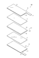
- FIG. 2 is an exploded perspective view showing an embodiment of the electrode group 2 of the secondary battery 1 shown in FIG.
- the electrode group 2A includes a positive electrode 6, an electrolyte layer 7, and a negative electrode 8 in this order.
- the positive electrode 6 includes a positive electrode current collector 9 and a positive electrode mixture layer 10 provided on the positive electrode current collector 9.
- a positive electrode current collector tab 4 is provided on the positive electrode current collector 9 of the positive electrode 6.
- the negative electrode 8 includes a negative electrode current collector 11 and a negative electrode mixture layer 12 provided on the negative electrode current collector 11.
- a negative electrode current collector tab 5 is provided on the negative electrode current collector 11 of the negative electrode 8.
- the electrode group 2A includes a first secondary battery battery member (positive electrode member) including the positive electrode current collector 9, the positive electrode mixture layer 10, and the electrolyte layer 7 in this order. You can see that.
- the electrode group 2A includes a second secondary battery battery member (negative electrode member) including the negative electrode current collector 11, the negative electrode mixture layer 12, and the electrolyte layer 7 in this order. You can also see it.
- the method for producing a battery member for a secondary battery (hereinafter sometimes simply referred to as “battery member”) according to each embodiment of the present invention is a method for producing the positive electrode member or the negative electrode member.
- FIG. 3 is a schematic cross-sectional view showing a method for manufacturing a battery member for a secondary battery according to an embodiment.
- an electrode active material is contained on one surface (main surface) 13a of the current collector 13 (positive electrode current collector 9 or negative electrode current collector 11).
- the electrode mixture intermediate layer 14 (positive electrode mixture intermediate layer or negative electrode mixture intermediate layer) is formed (electrode mixture intermediate layer forming step).
- the method of forming the electrode mixture intermediate layer 14 on the one surface 13a of the current collector 13 is as follows.
- the electrode mixture slurry is applied on the one surface 13a of the current collector 13. It is a method to do.
- the electrode mixture slurry is a slurry (positive electrode mixture slurry or negative electrode mixture slurry) in which the material contained in the positive electrode mixture layer 10 or the negative electrode mixture layer 12 is dispersed in a dispersion medium.
- the electrode mixture slurry of this embodiment contains at least an electrode active material (positive electrode active material or negative electrode active material) and a dispersion medium.
- the current collector 13 is the positive electrode current collector 9.
- the positive electrode current collector 9 may be a metal such as aluminum, titanium, or tantalum, or an alloy thereof. Since the positive electrode current collector 9 is light and has a high weight energy density, it is preferably aluminum or an alloy thereof.
- the thickness of the positive electrode current collector 9 may be 10 ⁇ m or more and may be 100 ⁇ m or less.
- the current collector 13 is the negative electrode current collector 11.
- the negative electrode current collector 11 may be a metal such as aluminum, copper, nickel, stainless steel, or an alloy thereof.
- the negative electrode current collector 11 is preferably aluminum or an alloy thereof because it is lightweight and has a high weight energy density.
- the negative electrode current collector 11 is preferably copper from the viewpoint of ease of processing into a thin film and cost.
- the thickness of the negative electrode current collector 11 may be 10 ⁇ m or more, and may be 100 ⁇ m or less.
- the electrode active material is a positive electrode active material.
- the positive electrode active material may be a lithium transition metal compound such as a lithium transition metal oxide or a lithium transition metal phosphate.
- the lithium transition metal oxide may be, for example, lithium manganate, lithium nickelate, lithium cobaltate, or the like.
- Lithium transition metal oxide is a part of transition metals such as Mn, Ni, Co, etc. contained in lithium manganate, lithium nickelate, lithium cobaltate, etc., one or more other transition metals, or A lithium transition metal oxide substituted with a metal element (typical element) such as Mg or Al may also be used. That is, the lithium transition metal oxide may be a compound represented by LiM 1 O 2 or LiM 1 O 4 (M 1 includes at least one transition metal).
- lithium transition metal oxides are Li (Co 1/3 Ni 1/3 Mn 1/3 ) O 2 , LiNi 1/2 Mn 1/2 O 2 , LiNi 1/2 Mn 3/2 O. It may be 4 mag.
- the lithium transition metal oxide is preferably a compound represented by the following formula (1).
- Lithium transition metal phosphates are LiFePO 4 , LiMnPO 4 , LiMn x M 3 1-x PO 4 (0.3 ⁇ x ⁇ 1, M 3 is Fe, Ni, Co, Ti, Cu, Zn, Mg and Zr) Or at least one element selected from the group consisting of:
- the positive electrode active material may be primary particles that are not granulated, or may be secondary particles that are granulated.
- the particle diameter of the positive electrode active material is adjusted to be equal to or less than the thickness of the positive electrode mixture layer 10.
- the coarse particles are removed in advance by sieving classification, wind classification, etc.
- a positive electrode active material having a diameter is selected.
- the average particle diameter of the positive electrode active material is preferably 0.1 ⁇ m or more, more preferably 1 ⁇ m or more.
- the average particle diameter of the positive electrode active material is preferably 30 ⁇ m or less, more preferably 25 ⁇ m or less.
- the average particle diameter of the positive electrode active material is the particle diameter (D 50 ) when the ratio (volume fraction) to the volume of the entire positive electrode active material is 50%.
- the average particle diameter (D 50 ) of the positive electrode active material is measured by suspending the positive electrode active material in water by a laser scattering method using a laser scattering particle size measuring device (for example, Microtrack). Can be obtained.
- the content of the positive electrode active material is 70% by mass or more, 80% by mass or more, or 90% based on the total amount of nonvolatile components in the positive electrode mixture slurry (a component obtained by removing the dispersion medium from the positive electrode mixture slurry; the same applies hereinafter). It may be not less than mass% and may be not more than 99 mass%. Thereby, content of the positive electrode active material in the positive electrode mixture layer obtained becomes content similar to content mentioned above.
- the electrode active material is a negative electrode active material.
- the negative electrode active material those commonly used in the field of energy devices can be used.
- Specific examples of the negative electrode active material include metal lithium, lithium titanate (Li 4 Ti 5 O 12 ), a lithium alloy or other metal compound, a carbon material, a metal complex, and an organic polymer compound. .
- the negative electrode active material may be one of these alone or a mixture of two or more.
- Carbon materials include natural graphite (flaky graphite, etc.), graphite such as artificial graphite, amorphous carbon, carbon fiber, acetylene black, ketjen black, channel black, furnace black, lamp black, thermal Examples thereof include carbon black such as black.
- the negative electrode active material may be silicon, tin, or a compound containing these elements (oxide, nitride, alloy with other metals). Good.
- the average particle diameter (D 50 ) of the negative electrode active material is preferably 1 ⁇ m or more from the viewpoint of obtaining a well-balanced negative electrode that suppresses an increase in irreversible capacity due to a decrease in particle diameter and has improved electrolyte salt retention ability. More preferably, it is 5 ⁇ m or more, more preferably 10 ⁇ m or more, preferably 50 ⁇ m or less, more preferably 40 ⁇ m or less, and further preferably 30 ⁇ m or less.
- the average particle diameter (D 50 ) of the negative electrode active material is measured by the same method as the average particle diameter (D 50 ) of the positive electrode active material described above.
- the content of the negative electrode active material is 60% by mass or more, 65% by mass or more, or 70% based on the non-volatile content in the negative electrode mixture slurry (a component obtained by removing the dispersion medium from the negative electrode mixture slurry; the same applies hereinafter). It may be not less than mass%, and may be not more than 99 mass%, not more than 95 mass%, or not more than 90 mass%. Thereby, content of the negative electrode active material in the obtained negative mix layer becomes content similar to content mentioned above.
- the dispersion medium may be water or an organic solvent.
- the organic solvent may be N-methyl-2-pyrrolidone (NMP), N, N-dimethylacetamide, methyl ethyl ketone, toluene, 2-butanol, cyclohexanone, ethyl acetate, 2-propanol, and preferably NMP.
- NMP N-methyl-2-pyrrolidone
- the content of the dispersion medium in the electrode mixture slurry is, for example, 20 parts by mass with respect to 100 parts by mass of the non-volatile content in the electrode mixture slurry (the component obtained by removing the dispersion medium from the electrode mixture slurry). It may be above and may be 1000 mass parts or less.
- the electrode mixture slurry may further contain a conductive agent, a binder and the like as other components.
- the electrode mixture intermediate layer 14 further containing these materials is formed.
- the conductive agent is not particularly limited, and may be a carbon material such as graphite, acetylene black, carbon black, or carbon fiber.
- the conductive agent may be a mixture of two or more carbon materials described above.
- the content of the conductive agent may be 1 to 70% by mass based on the total nonvolatile content in the electrode mixture slurry. Thereby, content of the electrically conductive agent in the electrode mixture layer obtained becomes content similar to content mentioned above.
- the binder is not particularly limited, but contains as a monomer unit at least one selected from the group consisting of ethylene tetrafluoride, vinylidene fluoride, hexafluoropropylene, acrylic acid, maleic acid, ethyl methacrylate, and methyl methacrylate. It may be a polymer, rubber such as styrene-butadiene rubber, isoprene rubber or acrylic rubber.
- the binder is preferably a copolymer containing hexafluoropropylene and vinylidene fluoride as structural units.
- the content of the binder may be 1 to 70% by mass based on the total nonvolatile content in the electrode mixture slurry. Thereby, content of the binder in the obtained electrode mixture layer becomes content similar to content mentioned above.
- the electrode mixture slurry may further contain an ionic liquid and an electrolyte salt described later, but preferably does not contain the ionic liquid and the electrolyte salt.
- examples of the method of applying the electrode mixture slurry include a method of applying using an applicator and a method of applying by spraying. By these methods, an electrode mixture slurry is applied onto one surface 13a of the current collector 13. As a result, as shown in FIG. 3A, the electrode mixture intermediate layer 14 is formed on the one surface 13 a of the current collector 13.
- the dispersion medium in the slurry may be volatilized. That is, the “electrode mixture intermediate layer” in this specification includes a layer formed of an electrode mixture slurry and a layer formed by volatilization of a part or all of the dispersion medium from the electrode mixture slurry. It is.
- the method of volatilizing the dispersion medium may be, for example, a method of drying by heating, a method of reducing pressure, a method of combining reduced pressure and heating, or the like. In the method of reducing the pressure, the pressure may be reduced to a vacuum state.
- the heating temperature for drying may be 50 to 150 ° C. The heating time may be changed depending on the temperature as long as the dispersion medium is sufficiently volatilized, but may be, for example, 1 minute to 48 hours.
- the oxide particles 16, the polymer 17, the surface of the electrode mixture intermediate layer 14 on the side opposite to the current collector 13, A slurry 15 containing an ionic liquid, an electrolyte salt, and a dispersion medium is applied.
- this slurry is also referred to as “electrolyte slurry”
- the step of applying the electrolyte slurry 15 is also referred to as “electrolyte slurry application step”.
- the oxide particles 16 are, for example, inorganic oxide particles.
- the inorganic oxide is an inorganic oxide containing, for example, Li, Mg, Al, Si, Ca, Ti, Zr, La, Na, K, Ba, Sr, V, Nb, B, Ge and the like as constituent elements. Good.
- the oxide particles 16 are preferably at least one selected from the group consisting of SiO 2 , Al 2 O 3 , AlOOH, MgO, CaO, ZrO 2 , TiO 2 , Li 7 La 3 Zr 2 O 12 , and BaTiO 3. Particles. Since the oxide particles 16 have polarity, it is possible to promote dissociation of the electrolyte in the electrolyte layer and improve battery characteristics.
- the oxide particles 16 may be rare earth metal oxides. Specifically, the oxide particles 16 are scandium oxide, yttrium oxide, lanthanum oxide, cerium oxide, praseodymium oxide, neodymium oxide, samarium oxide, eurobium oxide, gadolinium oxide, terbium oxide, dysprosium oxide, holmium oxide, erbium oxide, It may be thulium oxide, ytterbium oxide, lutetium oxide or the like.
- the oxide particles 16 may have a hydrophobic surface.
- the oxide particles usually have a hydroxyl group on the surface and tend to be hydrophilic.
- the oxide particles having a hydrophobic surface have fewer hydroxyl groups on the surface than the oxide particles having no hydrophobic surface. For this reason, when oxide particles having a hydrophobic surface are used, the affinity between the oxide particles and the ionic liquid is expected to improve because the ionic liquid is hydrophobic. Therefore, it is considered that the ionic liquid retention in the electrolyte layer 7 is further improved, and as a result, the ionic conductivity of the electrolyte layer 7 is improved.
- oxide particles having a hydrophobic surface are used, not only when the secondary battery is discharged at a relatively low current, but also the discharge characteristics when discharging at a relatively high current (for example, about 0.5 C) are improved. be able to.
- the oxide particles having a hydrophobic surface can be obtained by, for example, treating hydrophilic oxide particles with a surface treatment agent capable of imparting a hydrophobic surface. That is, the oxide particles having a hydrophobic surface mean oxide particles that have been surface-treated with a surface treatment agent.
- the surface treatment agent may be a silicon-containing compound.
- the oxide particles 16 may be surface-treated with a silicon-containing compound. That is, the oxide particle 16 may be one in which the surface of the oxide particle and the silicon atom of the silicon-containing compound are bonded via an oxygen atom.
- the silicon-containing compound is preferably at least one selected from the group consisting of halogen-containing alkylsilanes, alkoxysilanes, epoxy group-containing silanes, amino group-containing silanes, silazanes, and siloxanes.
- the halogen element in the halogen-containing alkylsilane may be chlorine, fluorine or the like.
- the halogen-containing alkylsilane (alkylchlorosilane) containing chlorine may be methyltrichlorosilane, dimethyldichlorosilane, trimethylchlorosilane, n-octyldimethylchlorosilane, or the like.
- the halogen-containing alkylsilane (fluoroalkylsilane) containing fluorine may be trifluoropropyltrimethoxysilane, tridecafluorooctyltrimethoxysilane, or the like.
- Alkoxysilanes are methyltrimethoxysilane, dimethyldimethoxysilane, phenyltrimethoxysilane, phenyltriethoxysilane, dimethoxydiphenylsilane, n-propyltrimethoxysilane, hexyltrimethoxysilane, tetraethoxysilane, methyltriethoxysilane, dimethyldi It may be ethoxysilane, n-propyltriethoxysilane, or the like.
- Epoxy group-containing silanes are 2- (3,4-epoxycyclohexyl) ethyltrimethoxysilane, 3-glycidoxypropylmethyldimethoxysilane, 3-glycidoxypropyltrimethoxysilane, 3-glycidoxypropylmethyldiethoxy. Silane, 3-glycidoxypropyltriethoxysilane and the like may be used.
- Amino group-containing silanes are N-2- (aminoethyl) -3-aminopropylmethyldimethoxysilane, N-2- (aminoethyl) -3-aminopropyltrimethoxysilane, 3-aminopropyltriethoxysilane, N- Phenyl-3-aminopropyltrimethoxysilane or the like may be used.
- Silazane may be hexamethyldisilazane or the like.
- Siloxane may be dimethyl silicone oil or the like.
- One or both of these terminals may have a reactive functional group (for example, a carboxyl group).
- oxide particles having a hydrophobic surface those produced by a known method may be used, or commercially available products may be used as they are.
- the oxide particles 16 generally include primary particles that integrally form a single particle (particles that do not constitute a secondary particle) and a plurality of primary particles, as determined from an apparent geometric form. Secondary particles formed by the aggregation of the particles may be included.
- the specific surface area of the oxide particles 16 is preferably 2 to 400 m 2 / g, 5 to 100 m 2 / g, 10 to 80 m 2 / g, or 15 to 60 m 2 / g.
- the specific surface area is 2 to 400 m 2 / g, the secondary battery including the electrolyte layer containing such oxide particles tends to have excellent discharge characteristics.
- the specific surface area of the oxide particles 16 may be 2 m 2 / g or more, 5 m 2 / g or more, 10 m 2 / g or more, 15 m 2 / g or more, or 50 m 2 / g or more, 400 m 2 / g or less, 350 m 2 / g or less, 300 m 2 / g or less, 200 m 2 / g or less, 100 m 2 / g or less, 90 m 2 / g or less, 80 m 2 / g or less, or 60 m 2 / g or less. May be.
- the specific surface area of the oxide particles 16 means the specific surface area of the whole oxide particles including primary particles and secondary particles, and is measured by the BET method.
- the average primary particle size of the oxide particles 16 (average particle size of the primary particles) is preferably 0.005 ⁇ m (5 nm) or more, more preferably 0.01 ⁇ m, from the viewpoint of improving the conductivity of the secondary battery 1. (10 nm) or more, more preferably 0.015 ⁇ m (15 nm) or more. From the viewpoint of making the electrolyte layer 7 thin, the average primary particle size of the oxide particles 16 is preferably 1 ⁇ m or less, more preferably 0.1 ⁇ m or less, and even more preferably 0.05 ⁇ m or less. The average primary particle size of the oxide particles 16 can be measured by observing the oxide particles 16 with a transmission electron microscope or the like.
- the average particle diameter of the oxide particles 16 is preferably 0.005 ⁇ m or more, more preferably 0.01 ⁇ m or more, and further preferably 0.03 ⁇ m or more.
- the average particle size of the oxide particles 16 is preferably 5 ⁇ m or less, more preferably 3 ⁇ m or less, and even more preferably 1 ⁇ m or less.
- the average particle diameter of the oxide particles 16 is measured by a laser diffraction method, and corresponds to the particle diameter at which the volume accumulation is 50% when the volume accumulation particle size distribution curve is drawn from the small particle diameter side.
- the content of the oxide particles 16 is preferably 1% by mass or more, more preferably 3% by mass based on the total amount of nonvolatile components in the electrolyte slurry 15 (a component obtained by removing the dispersion medium from the electrolyte slurry; the same applies hereinafter). % Or more, more preferably 5% by mass or more, particularly preferably 7% by mass or more, preferably 30% by mass or less, more preferably 27% by mass or less, and further preferably 25% or less. It is below mass%.
- the content of the oxide particles 16 is preferably 5% by volume or more, more preferably 7% by volume or more, and still more preferably 9% by volume, based on the total nonvolatile content in the electrolyte slurry 15. % Or more, preferably 20% by volume or less, more preferably 17% by volume or less, and still more preferably 15% by volume or less.
- Polymer 17 preferably has a first structural unit selected from the group consisting of ethylene tetrafluoride and vinylidene fluoride.
- the polymer 17 is preferably one or more kinds of polymers, and among the structural units constituting the one or more kinds of polymers, the first structural unit described above, hexafluoropropylene, acrylic A second structural unit selected from the group consisting of acid, maleic acid, ethyl methacrylate, and methyl methacrylate may be included. That is, the first structural unit and the second structural unit may be included in one kind of polymer to form a copolymer, and each of the first structural unit and the second structural unit may be included in another polymer and have the first structural unit. And at least two types of polymers, the second polymer having the second structural unit.
- the polymer 17 may be polytetrafluoroethylene, polyvinylidene fluoride, a copolymer of vinylidene fluoride and hexafluoropropylene, or the like.
- the content of the polymer 17 is preferably 3% by mass or more, preferably 60% by mass or less, more preferably 50% by mass or less, based on the total nonvolatile content in the electrolyte slurry 15. More preferably, it is 40 mass% or less.
- the ionic liquid contains the following anion component and cation component. Note that the ionic liquid in this specification is a liquid substance at ⁇ 20 ° C. or higher. In the secondary battery 1, the types of ionic liquids contained in the positive electrode member and the negative electrode member may be the same or different.
- the anion component of the ionic liquid is not particularly limited, but is an anion of a halogen such as Cl ⁇ , Br ⁇ and I ⁇ , an inorganic anion such as BF 4 ⁇ and N (SO 2 F) 2 — , B (C 6 H 5 ) 4 ⁇ , CH 3 SO 2 O ⁇ , CF 3 SO 2 O ⁇ , N (SO 2 C 4 F 9 ) 2 ⁇ , N (SO 2 CF 3 ) 2 ⁇ , N (SO 2 C 2 F 5 ) 2 ⁇ Or an organic anion.
- the anionic component of the ionic liquid preferably contains at least one anionic component represented by the following formula (2).
- Examples of the anion component represented by the formula (2) include N (SO 2 C 4 F 9 ) 2 ⁇ , N (SO 2 F) 2 ⁇ , N (SO 2 CF 3 ) 2 — and N (SO 2 C 2 F 5 ) 2 — .
- the anionic component of the ionic liquid is more preferably N (SO 2 C 4 F 9 ) 2 ⁇ , CF 3 SO from the viewpoint of further improving the ionic conductivity with a relatively low viscosity and further improving the charge / discharge characteristics. It contains at least one selected from the group consisting of 2 O ⁇ , N (SO 2 F) 2 ⁇ , N (SO 2 CF 3 ) 2 ⁇ , and N (SO 2 C 2 F 5 ) 2 — .
- the electrolyte slurry 15 more preferably contains N (SO 2 F) 2 — as an anion component.
- N (SO 2 F) 2 — is contained as an anion component, a good interface can be formed between the electrode mixture layer and the electrolyte layer in the obtained battery member. This effect is particularly remarkable in the negative electrode member. That is, in the method for producing a negative electrode member, the ionic liquid contained in the electrolyte slurry preferably contains N (SO 2 F) 2 — as an anion component.
- the cation component of the ionic liquid is preferably at least one selected from the group consisting of a chain quaternary onium cation, a piperidinium cation, a pyrrolidinium cation, a pyridinium cation, and an imidazolium cation.
- the chain quaternary onium cation is, for example, a compound represented by the following formula (3).
- R 1 to R 4 each independently represents a chain alkyl group having 1 to 20 carbon atoms, or a chain alkoxyalkyl group represented by R—O— (CH 2 ) n —.
- R represents a methyl group or an ethyl group, and n represents an integer of 1 to 4
- X represents a nitrogen atom or a phosphorus atom.
- the number of carbon atoms of the alkyl group represented by R 1 to R 4 is preferably 1 to 20, more preferably 1 to 10, and still more preferably 1 to 5.
- the piperidinium cation is, for example, a nitrogen-containing six-membered cyclic compound represented by the following formula (4).
- R 5 and R 6 are each independently an alkyl group having 1 to 20 carbon atoms or an alkoxyalkyl group represented by R—O— (CH 2 ) n — (R is methyl And n represents an integer of 1 to 4.
- the number of carbon atoms of the alkyl group represented by R 5 and R 6 is preferably 1 to 20, more preferably 1 to 10, and still more preferably 1 to 5.
- the pyrrolidinium cation is, for example, a five-membered cyclic compound represented by the following formula (5).
- R 7 and R 8 are each independently an alkyl group having 1 to 20 carbon atoms or an alkoxyalkyl group represented by R—O— (CH 2 ) n — (R is methyl And n represents an integer of 1 to 4.
- the carbon number of the alkyl group represented by R 7 and R 8 is preferably 1-20, more preferably 1-10, and still more preferably 1-5.
- the pyridinium cation is, for example, a compound represented by the following formula (6).
- R 9 to R 13 each independently represents an alkyl group having 1 to 20 carbon atoms, an alkoxyalkyl group represented by R—O— (CH 2 ) n — (R represents a methyl group) Or an ethyl group, and n represents an integer of 1 to 4), or a hydrogen atom.
- the number of carbon atoms of the alkyl group represented by R 9 to R 13 is preferably 1 to 20, more preferably 1 to 10, and still more preferably 1 to 5.
- the imidazolium cation is, for example, a compound represented by the following formula (7).
- R 14 to R 18 are each independently an alkyl group having 1 to 20 carbon atoms, an alkoxyalkyl group represented by R—O— (CH 2 ) n — (R is a methyl group) Or an ethyl group, and n represents an integer of 1 to 4), or a hydrogen atom.
- the number of carbon atoms of the alkyl group represented by R 14 to R 18 is preferably 1 to 20, more preferably 1 to 10, and still more preferably 1 to 5.
- the ionic liquid contained in the electrolyte slurry 15 is preferably N, N-diethyl-N-methyl-N- (2-methoxyethyl) ammonium-bis (trifluoromethanesulfonyl) imide (DEME-TFSI), N, N— Diethyl-N-methyl-N- (2-methoxyethyl) ammonium-bis (fluorosulfonyl) imide (DEME-FSI), 1-ethyl-3-methylimidazolium-bis (trifluoromethanesulfonyl) imide (EMI-TFSI) 1-ethyl-3-methylimidazolium-bis (fluorosulfonyl) imide (EMI-FSI), N-methyl-N-propylpyrrolidinium-bis (trifluoromethanesulfonyl) imide (Py13-TFSI), N-methyl -N-propylpyrrolidinium-bis (triflu
- the ionic liquid contained in the electrolyte slurry 15 is more preferably DEME-FSI, EMI-FSI, Py13-FSI, or Py12-FSI from the viewpoint of further improving the discharge characteristics at a relatively high current.
- the ionic liquid contained in the electrolyte slurry 15 is more preferably EMI-FSI from the viewpoint of further improving the discharge characteristics at a relatively high current.
- the electrolyte salt may be at least one selected from the group consisting of a lithium salt, a sodium salt, a calcium salt, and a magnesium salt.
- the anion component of the electrolyte salt includes halide ions (I ⁇ , Cl ⁇ , Br ⁇ etc.), SCN ⁇ , BF 4 ⁇ , BF 3 (CF 3 ) ⁇ , BF 3 (C 2 F 5 ) ⁇ , PF 6 ⁇ .
- the anion component of the electrolyte salt is preferably an anion component represented by the above formula (2) such as N (SO 2 F) 2 ⁇ , N (SO 2 CF 3 ) 2 — , PF 6 ⁇ , BF 4 ⁇ . , B (O 2 C 2 O 2 ) 2 ⁇ , or ClO 4 — .
- Lithium salts include LiPF 6 , LiBF 4 , Li [FSI], Li [TFSI], Li [f 3 C], Li [BOB], LiClO 4 , LiBF 3 (CF 3 ), LiBF 3 (C 2 F 5 ), LiBF 3 (C 3 F 7 ), LiBF 3 (C 4 F 9 ), LiC (SO 2 CF 3 ) 3 , LiCF 3 SO 2 O, LiCF 3 COO, and LiRCOO (R is an alkyl group having 1 to 4 carbon atoms) , A phenyl group, or a naphthyl group).
- Sodium salts include NaPF 6 , NaBF 4 , Na [FSI], Na [TFSI], Na [f 3 C], Na [BOB], NaClO 4 , NaBF 3 (CF 3 ), NaBF 3 (C 2 F 5 ), NaBF 3 (C 3 F 7 ), NaBF 3 (C 4 F 9 ), NaC (SO 2 CF 3 ) 3 , NaCF 3 SO 2 O, NaCF 3 COO, and NaRCOO (R is an alkyl group having 1 to 4 carbon atoms) , A phenyl group, or a naphthyl group).
- the calcium salts are Ca (PF 6 ) 2 , Ca (BF 4 ) 2 , Ca [FSI] 2 , Ca [TFSI] 2 , Ca [f3C] 2 , Ca [BOB] 2 , Ca (ClO 4 ) 2 , Ca [BF 3 (CF 3 )] 2 , Ca [BF 3 (C 2 F 5 )] 2 , Ca [BF 3 (C 3 F 7 )] 2 , Ca [BF 3 (C 4 F 9 )] 2 , Ca [C (SO 2 CF 3 ) 3 ] 2 , Ca (CF 3 SO 2 O) 2 , Ca (CF 3 COO) 2 , and Ca (RCOO) 2 (R is an alkyl group having 1 to 4 carbon atoms, phenyl Or at least one selected from the group consisting of a naphthyl group).
- Magnesium salts are Mg (PF 6 ) 2 , Mg (BF 4 ) 2 , Mg [FSI] 2 , Mg [TFSI] 2 , Mg [f 3 C] 2 , Mg [BOB] 2 , Mg (ClO 4 ) 2 , Mg [BF 3 (CF 3 )] 2 , Mg [BF 3 (C 2 F 5 )] 2 , Mg [BF 3 (C 3 F 7 )] 2 , Mg [BF 3 (C 4 F 9 )] 2 , Mg [C (SO 2 CF 3 ) 3 ] 2 , Mg (CF 3 SO 3 ) 2 , Mg (CF 3 COO) 2 , and Mg (RCOO) 2 (R is an alkyl group having 1 to 4 carbon atoms, a phenyl group Or a naphthyl group) may be at least one selected from the group consisting of:
- the electrolyte salt is preferably LiPF 6 , LiBF 4 , Li [FSI], Li [TFSI], Li [f 3 C], Li [BOB], LiClO 4.
- LiBF 3 (CF 3 ), LiBF 3 (C 2 F 5 ), LiBF 3 (C 3 F 7 ), LiBF 3 (C 4 F 9 ), LiC (SO 2 CF 3 ) 3 , LiCF 3 SO 2 O It is at least one selected from the group consisting of LiCF 3 COO and LiRCOO (where R is an alkyl group having 1 to 4 carbon atoms, a phenyl group, or a naphthyl group), more preferably Li [TFSI], Li [FSI], LiPF 6, LiBF 4, Li [BOB], and at least one selected from the group consisting of LiClO 4, more preferably Li [TF I], and is one selected from the group consisting of Li [FSI].
- the electrolyte slurry may contain an ionic liquid and an electrolyte salt as an “ionic liquid electrolytic solution” in which the electrolyte salt is dissolved in the ionic liquid.
- the salt concentration of the electrolyte salt per unit volume of the ionic liquid is preferably greater than 0.5 mol / L.
- the salt concentration of the electrolyte salt per unit volume of the ionic liquid is more preferably 0.7 mol / L or more, and further preferably 1.0 mol / L or more.
- the salt concentration of the electrolyte salt per unit volume of the ionic liquid is preferably 3.0 mol / L or less, more preferably 2. mol / L or less, from the viewpoint of suppressing a decrease in ionic conductivity due to excessive inclusion of the electrolyte salt. 7 mol / L or less, more preferably 2.5 mol / L or less.
- the content of the ionic liquid electrolyte (the total content of the ionic liquid and the electrolyte salt) is determined in view of obtaining a uniform dispersion state in the electrolyte slurry 15, and the electrode mixture layer (the positive electrode mixture layer 10 or the negative electrode mixture layer). 12) From the viewpoint of satisfactorily forming the interface between the electrolyte layer 7, it is preferably 20% by mass or more, more preferably 25% by mass or more, and still more preferably, based on the total nonvolatile content in the electrolyte slurry 15. 30% by mass or more. Thereby, the ionic conductivity of the electrolyte layer 7 can be raised and the battery characteristic of a secondary battery can be improved further.
- the content of the ionic liquid electrolytic solution may be 90% by mass or less, 85% by mass or less, or 80% by mass or less based on the total nonvolatile content in the electrolyte slurry 15.
- the content of the ionic liquid electrolytic solution (the total content of the ionic liquid and the electrolyte salt) is determined in view of obtaining a uniform dispersion state in the electrolyte slurry 15, and the electrode mixture layer (the positive electrode mixture layer 10).
- it is preferably 35% by volume or more, more preferably 40% by volume or more, based on the total nonvolatile content in the electrolyte slurry 15. Yes, more preferably 45% by volume or more.
- the content of the ionic liquid electrolytic solution may be 90% by volume or less, 85% by volume or less, or 80% by volume or less based on the total nonvolatile content in the electrolyte slurry 15.
- the dispersion medium in the electrolyte slurry 15 may be the same as the dispersion medium used for the electrode mixture slurry described above.
- the content of the dispersion medium in the electrolyte slurry 15 may be, for example, 5 parts by mass or more and 1000 parts by mass or less with respect to 100 parts by mass of the non-volatile content in the electrolyte slurry 15.
- the ratio of the total content of the ionic liquid and the electrolyte salt to the content of the oxide particles 16 is larger than 4/1 by volume ratio (volume of the ionic liquid electrolyte / volume of the oxide particles). / Less than 1.
- the ratio of the total content of the ionic liquid and the electrolyte salt to the content of the oxide particles 16 is preferably 5/1 or more, and more preferably. Is 6/1 or more.
- the ratio of the total salt content is, in volume ratio, preferably 11/1 or less, more preferably 10/1 or less, still more preferably 9/1 or less, and particularly preferably 8/1 or less. It is.
- the ratio of the content of the oxide particles 16 to the content of the polymer 17 is preferably a mass ratio (content of oxide particles / content of polymer) from the viewpoint of improving the strength of the electrolyte layer. Is 1/5 or more, more preferably 1/4 or more, still more preferably 1/3 or more, and particularly preferably 1/2 or more. From the viewpoint of improving the discharge characteristics at a relatively high current, the ratio of the content of the oxide particles 16 to the content of the polymer 17 is preferably 5/1 or less, more preferably 3/1, from the viewpoint of improving the discharge characteristics at a relatively high current. Or less, more preferably 1/1 or less, and particularly preferably 2/3 or less.
- the method of applying the electrolyte slurry 15 on the one surface (main surface) 14a of the electrode mixture intermediate layer 14 is a method of applying the electrode mixture slurry described above on the one surface 13a of the current collector 13. It may be the same.
- the method of applying the electrolyte slurry 15 may be the same as or different from the method of applying the electrode mixture slurry.
- the dispersion medium contained in the electrode mixture intermediate layer 14 and the electrolyte slurry 15 is volatilized.
- the method for volatilizing the dispersion medium may be the same as the method for volatilizing the dispersion medium in the electrode mixture slurry described above.
- the current collector 13, the electrode mixture layer 18 (the positive electrode mixture layer 10 or the negative electrode mixture layer). 12) and the battery member 19 for a secondary battery (positive electrode member or negative electrode member) including the electrolyte layer 7 in this order can be obtained.
- the secondary battery using the battery member 19 obtained by the manufacturing method of the present embodiment is particularly excellent in discharge characteristics when the secondary battery is discharged at a relatively low current.
- the electrolyte slurry 15 when the electrolyte slurry 15 is applied on the electrode mixture intermediate layer 14, as shown by the arrow in FIG.
- the slurry moves from the slurry 15 to the electrode mixture intermediate layer 14. This movement is presumed to be based on the action of reducing the concentration difference of the ionic liquid electrolyte solution between the electrode mixture intermediate layer 14 and the electrolyte slurry 15, the action of gravity, or the capillary phenomenon.
- the electrolyte layer 7 is formed by applying the electrolyte slurry 15 on the electrode mixture intermediate layer 14, there are fine irregularities on the surface of the electrode mixture intermediate layer 14. Also, the electrolyte slurry 15 is arranged so as to fill the recess and flatten it. As a result, in the obtained battery member 19, a good interface is formed in which the electrode mixture layer 18 and the electrolyte layer 7 are closely adhered. In the battery member 19, since the ionic liquid electrolyte can move between the electrolyte slurry 15 and the electrode mixture intermediate layer 14 in the electrolyte slurry coating step, the ionic liquid electrolyte is contained in the electrode mixture layer 18. Tends to exist around the electrode active material. Therefore, in the battery member 19, the electrode active material / electrolyte interface is satisfactorily formed.
- the electrode mixture layer 18 / electrolyte layer 7 interface is well formed and has excellent adhesion, and the electrode active material / electrolyte interface is also well formed. The Therefore, the secondary battery using this battery member 19 is further excellent in battery characteristics.
- a method for manufacturing a secondary battery includes a step of infiltrating a solution (polymer solution) containing a polymer into the electrode mixture intermediate layer 14 before applying the electrolyte slurry 15 (polymer solution infiltration). Step) may be further provided.
- the polymer solution contains a polymer having a structural unit represented by the following formula (8), an ionic liquid, and an electrolyte salt.
- X ⁇ represents a counter anion.
- X ⁇ include BF 4 ⁇ (tetrafluoroborate anion), PF 6 ⁇ (hexafluorophosphate anion), [FSI] ⁇ , [TFSI] ⁇ , [f3C] ⁇ , [BOB] ⁇ , and BF.
- X ⁇ is preferably at least one selected from the group consisting of BF 4 ⁇ , PF 6 ⁇ , [FSI] ⁇ , [TFSI] ⁇ , and [f3C] ⁇ , more preferably [TFSI] ⁇ . Or [FSI] ⁇ .
- the viscosity average molecular weight Mv (g ⁇ mol ⁇ 1 ) of the polymer having the structural unit represented by the formula (8) is not particularly limited, but is preferably 1.0 ⁇ 10 5 or more, more preferably 3.0. ⁇ 10 5 or more.
- the viscosity average molecular weight of the polymer is preferably 5.0 ⁇ 10 6 or less, and more preferably 1.0 ⁇ 10 6 .
- the handling property when penetrating the polymer solution tends to be further increased.
- the “viscosity average molecular weight” can be evaluated by a viscosity method which is a general measurement method. For example, from the intrinsic viscosity [ ⁇ ] measured based on JIS K 7367-3: 1999. Can be calculated.
- the polymer having the structural unit represented by the formula (8) is preferably a polymer consisting only of the structural unit represented by the formula (8), that is, a homopolymer, from the viewpoint of ion conductivity.
- the polymer having the structural unit represented by the formula (8) may be a polymer represented by the following formula (8A).
- n 300 to 4000
- Y ⁇ represents a counter anion.
- Y ⁇ those similar to those exemplified for X ⁇ can be used.
- N is 300 or more, preferably 400 or more, more preferably 500 or more, and may be 4000 or less, preferably 3500 or less, more preferably 3000 or less.
- n is 300 to 4000, preferably 400 to 3500, more preferably 500 to 3000.
- the production method of the polymer having the structural unit represented by the formula (8) is not particularly limited, and for example, the production method described in Journal of Power Sources 2009, 188, 558-563 can be used.
- poly (diallyldimethylammonium) chloride [P (DADMA)] [Cl]
- P (DADMA)] [Cl] poly (diallyldimethylammonium) chloride
- a commercially available product can be used as it is.
- Li [TFSI] is dissolved in deionized water to prepare an aqueous solution containing Li [TFSI].
- the molar ratio of Li [TFSI] to [P (DADMA)] [Cl] (molar amount of Li [TFSI] / molar amount of [P (DADMA)] [Cl]) was 1.2 to 2.0.
- the two aqueous solutions are mixed and stirred for 2 to 8 hours to precipitate a solid, and the obtained solid is collected by filtration.
- the polymer ([P (DADMA)] [TFSI]) having the structural unit represented by the formula (8) can be obtained by washing the solid with deionized water and vacuum-drying for 12 to 48 hours. .
- the polymer having the structural unit represented by the formula (8) is preferably 10% by mass or more, more preferably 20% by mass or more, and further preferably 30% by mass or more, based on the total amount of the polymer solution. Moreover, it is preferably 80% by mass or less, more preferably 75% by mass or less, and further preferably 70% by mass or less.
- the ionic liquid and electrolyte salt contained in the polymer solution may be the same as the ionic liquid and electrolyte salt that can be used in the above-described embodiment.
- the ionic liquid and electrolyte salt contained in the polymer solution may be the same as or different from the ionic liquid and electrolyte salt contained in the electrolyte slurry 15.
- the ionic liquid and the electrolyte salt may be added to the polymer solution as an ionic liquid electrolytic solution.
- the salt concentration of the electrolyte salt per unit volume of the ionic liquid may be 0.3 mol / L or more, 0.5 mol / L or more, or 1.0 mol / L or more. It may be 0.0 mol / L or less, 2.7 mol / L or less, or 2.5 mol / L or less.
- the content of the ionic liquid electrolytic solution is preferably 3% by mass or more, more preferably 5% by mass or more, still more preferably 10% by mass or more, and preferably 80% based on the total amount of the polymer solution. It is not more than mass%, more preferably not more than 75 mass%, still more preferably not more than 70 mass%.
- the polymer solution may further contain a dispersion medium.
- the dispersion medium may be an organic solvent, such as acetone, ethyl methyl ketone, ⁇ -butyrolactone, and the like.
- the polymer solution infiltration step the polymer solution is infiltrated into the electrode mixture intermediate layer 14 by, for example, a method of applying the polymer solution on the surface 14a of the electrode mixture intermediate layer 14 opposite to the current collector 13. is there.
- the application may be application by an applicator, application by spraying, or the like.
- the polymer solution applied on the electrode mixture intermediate layer 14 penetrates into the electrode mixture intermediate layer 14 to form an electrode mixture intermediate layer containing a polymer having a structural unit represented by the formula (8).
- the method of allowing the polymer solution to penetrate into the electrode mixture intermediate layer 14 may be, for example, a method of immersing the current collector 13 on which the electrode mixture intermediate layer 14 is formed in the polymer solution.
- an electrolyte slurry 15 is applied on the surface 14a opposite to the current collector 13 of the electrode mixture intermediate layer 14 (electrode mixture intermediate layer infiltrated with the polymer solution). (Electrolyte slurry coating process).
- the composition and application method of the electrolyte slurry 15 may be the same as those in the above-described embodiment.
- the polymer represented by the above-described formula (8) is included in the electrode mixture layer 18.
- the ionic conductivity of the electrode mixture layer 18 can be increased, and the battery characteristics of the secondary battery using the battery member 19 can be further improved.
- the secondary battery including the battery member manufactured by the above-described manufacturing method can take various modifications.
- FIG. 4 is an exploded perspective view showing an embodiment of an electrode group of a secondary battery according to a modification.
- the electrode group 2 ⁇ / b> B includes the bipolar electrode 21. That is, as shown in FIG. 4, the electrode group 2 ⁇ / b> B includes a positive electrode 6, a first electrolyte layer 7, a bipolar electrode 21, a second electrolyte layer 7, and a negative electrode 8 in this order.
- the bipolar electrode 21 includes a bipolar current collector 22, a positive electrode mixture layer 10 provided on a surface (positive electrode surface) on the negative electrode 8 side of the bipolar current collector 22, and a surface on the positive electrode 6 side of the bipolar current collector 22 ( And a negative electrode mixture layer 12 provided on the negative electrode surface).
- This bipolar secondary battery includes a first electrolyte layer 7, a positive electrode mixture layer 10, a bipolar current collector 22, a negative electrode mixture layer 12, and a second electrolyte layer 7 in this order. It can be seen that a battery battery member (bipolar electrode member) is included.
- the battery member manufacturing method according to an embodiment of the present invention is a method of manufacturing this bipolar electrode member.
- the method of manufacturing a bipolar electrode member includes a step of forming a positive electrode mixture intermediate layer on one surface (one main surface) of the bipolar current collector 22 (positive electrode mixture intermediate layer forming step); A step of applying a first electrolyte slurry on the surface of the positive electrode mixture intermediate layer opposite to the bipolar current collector 22 (first electrolyte slurry applying step), and the other surface (the other side) of the bipolar current collector 22 Of the negative electrode mixture intermediate layer on the surface of the negative electrode mixture intermediate layer opposite to the bipolar current collector 22, and a second electrolyte slurry. And a step of applying (second electrolyte slurry applying step).
- Each process may be implemented by the same material and method as each process (electrode mixture intermediate layer forming process, electrolyte slurry coating process) in each embodiment described above.
- the composition of the first electrolyte slurry and the second electrolyte slurry may be the same composition or different compositions, but is preferably the same composition.
- a solution containing a polymer having a structural unit represented by the above formula (8) is infiltrated into the positive electrode mixture intermediate layer or the negative electrode mixture intermediate layer.
- a step may be further provided.
- the polymer solution infiltration step may be performed by the same material and method as the polymer solution infiltration step in the above-described embodiment.
- the positive electrode mixture intermediate layer and the first electrolyte slurry dispersion medium are volatilized.
- the dispersion medium of the negative electrode mixture intermediate layer and the second electrolyte slurry is volatilized.
- the method for volatilizing the dispersion medium may be the same as the method in the above-described embodiment.
- a battery member for a secondary battery comprising the first electrolyte layer 7, the positive electrode mixture layer 10, the bipolar current collector 22, the negative electrode mixture layer 12, and the second electrolyte layer 7 in this order. (Bipolar electrode member) can be obtained.
- the electrolyte layer 7 As a second modification, in the battery member manufacturing method according to each of the above-described embodiments, after the electrolyte layer 7 is formed, another electrolyte layer (second electrolyte layer) is formed on the electrolyte layer (first electrolyte layer) 7.
- the step of laminating the electrolyte layer) may be further provided.
- the first electrolyte layer plays a role in favorably forming the interface between the electrode mixture layer and the second electrolyte layer, the first electrolyte layer can also be called an interface forming layer.
- a secondary battery using a battery member obtained by this manufacturing method includes a positive electrode current collector, a positive electrode mixture layer, a first interface forming layer, an electrolyte layer (second electrolyte layer), a second electrode group as an electrode group.
- An interface forming layer, a negative electrode mixture layer, and a negative electrode current collector are provided in this order.
- the electrode group includes a first battery member (positive electrode member) including a positive electrode current collector, a positive electrode mixture layer, a first interface forming layer, and an electrolyte layer in this order. You can see that.
- the electrode group includes a second battery member (negative electrode member) including a negative electrode current collector, a negative electrode mixture layer, a second interface forming layer, and an electrolyte layer in this order. Can also be seen.
- the manufacturing method according to the second modification is a manufacturing method of the positive electrode member and the negative electrode member.
- the interface forming layer may have the same composition as the electrolyte layer in the battery member of each embodiment described above. That is, the manufacturing method according to this modification is a method in which the electrolyte layer is replaced with the interface forming layer in each of the above-described embodiments.
- the battery member can be manufactured by disposing the electrolyte layer on the surface on the first interface forming layer side of the positive electrode member or on the surface of the negative electrode member on the second interface forming layer side.
- the electrolyte layer at this time may be one in which the electrolyte slurry 15 described above is formed in a sheet shape. That is, a base material such as a resin film is prepared, and the electrolyte slurry 15 is applied on the base material, and then the dispersion medium is volatilized to prepare an electrolyte sheet. And an electrolyte layer can be obtained by peeling a base material from this electrolyte sheet.
- the electrolyte layer may have a composition different from that of the electrolyte layer produced from the electrolyte slurry 15, for example, a known electrolyte composition such as an organic polymer solid electrolyte or an inorganic solid electrolyte. May be previously formed into a sheet shape.
- a known electrolyte composition such as an organic polymer solid electrolyte or an inorganic solid electrolyte. May be previously formed into a sheet shape.
- the organic polymer solid electrolyte may be polyethylene oxide or the like
- the inorganic solid electrolyte may be Li 7 La 3 Zr 2 O 12 , Li 6.75 La 3 Zr 1.75 Nb 0.25 O 12 (LLZ— Nb), Li 6.75 La 3 Zr 1.75 Ta 0.25 O 12 , Li 1 + c + d Al c (Ti, Ge) 2-c Si d P 3-d O 12 (where 0 ⁇ c ⁇ 2 Yes, 0 ⁇ d ⁇ 3, where (Ti, Ge) means either Ti or Ge, or both Ti and Ge.), Li 10 GeP 2 S 12 , Li 9.54 Si 1.74 P 1.44 S 11.7 Cl 0.3 or the like.
- the discharge characteristics of the secondary battery when discharged at a relatively low current can be improved. Furthermore, when the ionic liquid electrolyte is included in the interface forming layer, ionic conduction between the interface forming layer and the electrolyte layer becomes easier. As a result, the secondary battery using the battery member according to this modification has excellent battery characteristics because it can be said that the interface between the layers is well formed.
- composition of an ionic liquid ionic liquid electrolytic solution
- concentration of electrolyte salt / type of electrolyte salt / type of ionic liquid it may be expressed as “concentration of electrolyte salt / type of electrolyte salt / type of ionic liquid”.
- Example 1 [Production of positive electrode member] 92.5 parts by mass of layered lithium / nickel / manganese / cobalt composite oxide (positive electrode active material) and acetylene black (conductive agent, product name: HS-100, average particle size 48 nm, manufactured by Denka Corporation) 2.5 A positive electrode mixture prepared by dispersing 5 parts by mass of a copolymer part (solid content: 12% by mass) of vinylidene fluoride and hexafluoropropylene in an appropriate amount of N-methyl-2-pyrrolidone (NMP) as a dispersion medium. A slurry was prepared.
- NMP N-methyl-2-pyrrolidone
- This positive electrode mixture slurry was applied onto a positive electrode current collector (aluminum foil having a thickness of 20 ⁇ m) at a coating amount of 125 g / m 2 , heated at 80 ° C. for 12 hours, dried, and pressed, whereby the mixture was obtained.
- a positive electrode mixture intermediate layer having a density of 2.7 g / cm 3 was formed. This was cut into a width of 30 mm and a length of 45 mm, and then a positive electrode current collecting tab was attached.
- the content of SiO 2 particles was 9% by volume and the content of the ionic liquid electrolyte was 70% by volume, based on the total amount of nonvolatile content of the electrolyte slurry.
- the obtained electrolyte slurry was applied on the surface of the positive electrode mixture intermediate layer opposite to the positive electrode current collector, and heated at 80 ° C. for 12 hours to volatilize the dispersion medium to form an electrolyte layer. Thereby, the positive electrode member provided with a positive electrode collector, a positive mix layer, and an electrolyte layer in this order was obtained.
- the thickness of the electrolyte layer in the obtained positive electrode member was 15 ⁇ 2 ⁇ m.
- This negative electrode mixture slurry was coated on a current collector (copper foil having a thickness of 10 ⁇ m) at a coating amount of 60 g / m 2 , heated at 80 ° C. for 12 hours, dried, and pressed to obtain a mixture density.
- a negative electrode mixture intermediate layer of 1.8 g / cm 3 was formed. This was cut into a width of 31 mm and a length of 46 mm, and then a negative electrode current collecting tab was attached.
- the dispersion medium is volatilized to form an electrolyte layer by the same method as the positive electrode member manufacturing method. It was. Thereby, the negative electrode member provided with the negative electrode current collector, the negative electrode mixture layer, and the electrolyte layer in this order was obtained.
- the thickness of the electrolyte layer in the obtained negative electrode member was 15 ⁇ 2 ⁇ m.
- the produced positive electrode member and negative electrode member were laminated so that the respective electrolyte layers were in contact with each other, thereby producing an electrode group.
- this electrode group was housed in a battery exterior body made of an aluminum laminate film.
- the positive electrode current collection tab and the negative electrode current collection tab were taken out to seal the opening of the battery container, thereby producing a lithium ion secondary battery.
- the aluminum laminate film is a laminate of polyethylene terephthalate (PET) film / aluminum foil / sealant layer (polypropylene, etc.).
- PET polyethylene terephthalate
- the designed capacity of the produced lithium ion secondary battery was 20 mAh.
- Examples 2 to 22 Reference Examples 1 and 2> A lithium ion secondary battery was produced in the same manner as in Example 1 except that the composition of the electrolyte slurry was changed to that shown in Table 1 in the production of the positive electrode member and the negative electrode member.
- the oxide particles that are surface-treated with an average primary particle size of 40 nm are the same SiO 2 particles as in Example 1, and the average primary particle size is 40 nm and the surface treatment is not performed.
- the one is AEROSIL OX50 (product name) manufactured by Nippon Aerosil Co., Ltd., and the one having an average primary particle size of 7 nm is S5130 (product name) manufactured by SIGMA-ALDRICH.
- Discharge capacity retention rate (%) (discharge capacity at current value 0.2 C or 0.5 C / discharge capacity at current value 0.1 C) ⁇ 100
Abstract
本発明の一側面は、集電体の一面上に、電極活物質を含有する電極合剤中間層を形成する工程と、電極合剤中間層の集電体とは反対側の面上に、酸化物粒子、ポリマ、イオン液体及び電解質塩を含有するスラリを塗布する工程と、を備え、酸化物粒子の含有量に対するイオン液体及び電解質塩の含有量の合計は、体積比で4/1より大きく12/1より小さい、二次電池用電池部材の製造方法を提供する。
Description
本発明は、二次電池用電池部材の製造方法に関する。
近年、携帯型電子機器、電気自動車等の普及により、高性能な二次電池が必要とされている。中でもリチウム二次電池は、高いエネルギ密度を有するため、電気自動車用電池、電力貯蔵用電池等の電源として注目されている。具体的には、電気自動車用電池としてのリチウム二次電池は、エンジンを搭載しないゼロエミッション電気自動車、エンジン及び二次電池の両方を搭載したハイブリッド電気自動車、電力系統から直接充電させるプラグイン・ハイブリッド電気自動車等の電気自動車に採用されている。また、電力貯蔵用電池としてのリチウム二次電池は、電力系統が遮断された非常時に、予め貯蔵しておいた電力を供給する定置式電力貯蔵システム等に用いられている。
このような広範な用途に使用するために、より高いエネルギ密度のリチウム二次電池が求められており、その開発がなされている。特に、電気自動車用のリチウム二次電池には、高い入出力特性及び高いエネルギ密度に加えて、高い安全性が要求されるため、安全性を確保するためのより高度な技術が求められる。リチウム二次電池の安全性を向上させる方法として、電解液を固体電解質へ変更する方法等が知られている(例えば特許文献1)。
固体電解質を用いたリチウム二次電池において、用途に応じて、例えば0.2C程度の、比較的低電流で放電した場合の放電特性の向上が重要となる場合がある。そこで本発明は、二次電池を比較的低電流で放電した場合の放電特性を向上させることができる二次電池用電池部材の製造方法を提供することを目的とする。
本発明の一側面は、集電体の一面上に、電極活物質を含有する電極合剤中間層を形成する工程と、電極合剤中間層の集電体とは反対側の面上に、酸化物粒子、ポリマ、イオン液体及び電解質塩を含有するスラリを塗布する工程と、を備え、酸化物粒子の含有量に対するイオン液体及び電解質塩の含有量の合計は、体積比で4/1より大きく12/1より小さい、二次電池用電池部材の製造方法を提供する。
酸化物粒子の比表面積は、好ましくは、2~400m2/gである。
イオン液体の単位体積あたりの電解質塩の濃度は、好ましくは、0.5mol/Lより大きい。
イオン液体は、好ましくは、アニオン成分として、N(SO2F)2
-を含有する。
本発明によれば、二次電池を比較的低電流で放電した場合の放電特性を向上させることができる二次電池用電池部材の製造方法を提供することができる。より具体的には、0.2Cで放電した場合において、二次電池の放電特性を向上させることができる二次電池用電池部材の製造方法を提供することができる。
以下、図面を適宜参照しながら、本発明の実施形態について説明する。ただし、本発明は以下の実施形態に限定されるものではない。以下の実施形態において、その構成要素(ステップ等も含む)は、特に明示した場合を除き、必須ではない。各図における構成要素の大きさは概念的なものであり、構成要素間の大きさの相対的な関係は各図に示されたものに限定されない。
本明細書における数値及びその範囲は、本発明を制限するものではない。本明細書において「~」を用いて示された数値範囲は、「~」の前後に記載される数値をそれぞれ最小値及び最大値として含む範囲を示す。本明細書において段階的に記載されている数値範囲において、一つの数値範囲で記載された上限値又は下限値は、他の段階的な記載の上限値又は下限値に置き換えてもよい。また、本明細書中に記載される数値範囲において、その数値範囲の上限値又は下限値は、実施例に示されている値に置き換えてもよい。
なお、本明細書では下記の略称を用いる場合がある。
[Py13]+:N-メチル-N-プロピルピロリジニウムカチオン
[EMI]+:1-エチル-3-メチルイミダゾリウムカチオン
[DEME]+:N,N-ジエチル-N-メチル-N-(2-メトキシエチル)アンモニウムカチオン
[FSI]-:N(SO2F)2 -、ビス(フルオロスルホニル)イミドアニオン
[TFSI]-:N(SO2CF3)2 -、ビス(トリフルオロメタンスルホニル)イミドアニオン
[f3C]-:C(SO2F)3 -、トリス(フルオロスルホニル)カルボアニオン
[BOB]-:B(O2C2O2)2 -、ビスオキサレートボラートアニオン
[P(DADMA)][Cl]:ポリ(ジアリルジメチルアンモニウム)クロライド
[P(DADMA)][TFSI]:ポリ(ジアリルジメチルアンモニウム)ビス(トリフルオロメタンスルホニル)イミド
図1は、一実施形態に係る二次電池を示す斜視図である。図1に示すように、二次電池1は、正極、負極及び電解質層から構成される電極群2と、電極群2を収容する袋状の電池外装体3とを備えている。正極及び負極には、それぞれ正極集電タブ4及び負極集電タブ5が設けられている。正極集電タブ4及び負極集電タブ5は、それぞれ正極及び負極が二次電池1の外部と電気的に接続可能なように、電池外装体3の内部から外部へ突き出している。
電池外装体3は、例えばラミネートフィルムで形成されていてよい。ラミネートフィルムは、例えば、ポリエチレンテレフタレート(PET)フィルム等の樹脂フィルムと、アルミニウム、銅、ステンレス鋼等の金属箔と、ポリプロピレン等のシーラント層とがこの順で積層された積層フィルムであってよい。
図2は、図1に示した二次電池1の電極群2の一実施形態を示す分解斜視図である。図2に示すように、電極群2Aは、正極6、電解質層7及び負極8をこの順に備える。正極6は、正極集電体9と、正極集電体9上に設けられた正極合剤層10とを備えている。正極6の正極集電体9には、正極集電タブ4が設けられている。負極8は、負極集電体11と、負極集電体11上に設けられた負極合剤層12とを備えている。負極8の負極集電体11には、負極集電タブ5が設けられている。
一実施形態において、電極群2Aには、正極集電体9と、正極合剤層10と、電解質層7とをこの順に備える第1の二次電池用電池部材(正極部材)が含まれていると見ることができる。同様に、電極群2Aには、負極集電体11と、負極合剤層12と、電解質層7とをこの順に備える第2の二次電池用電池部材(負極部材)が含まれていると見ることもできる。本発明の各実施形態に係る二次電池用電池部材(以下、単に「電池部材」ということもある。)の製造方法は、この正極部材又は負極部材の製造方法である。
図3は、一実施形態に係る二次電池用電池部材の製造方法を示す模式断面図である。この製造方法では、まず、図3(a)に示すように、集電体13(正極集電体9又は負極集電体11)の一面(主面)13a上に、電極活物質を含有する電極合剤中間層14(正極合剤中間層又は負極合剤中間層)を形成する(電極合剤中間層形成工程)。
電極合剤中間層形成工程において、集電体13の一面13a上に電極合剤中間層14を形成する方法は、一実施形態において、電極合剤スラリを集電体13の一面13a上に塗布する方法である。電極合剤スラリは、正極合剤層10又は負極合剤層12に含まれる材料を分散媒に分散させたスラリ(正極合剤スラリ又は負極合剤スラリ)である。本実施形態の電極合剤スラリは、少なくとも電極活物質(正極活物質又は負極活物質)及び分散媒を含有する。
電池部材が正極部材である場合、集電体13は正極集電体9である。正極集電体9は、アルミニウム、チタン、タンタル等の金属、又はそれらの合金であってよい。正極集電体9は、軽量で高い重量エネルギ密度を有するため、好ましくはアルミニウム又はその合金である。正極集電体9の厚さは、10μm以上であってよく、100μm以下であってよい。
電池部材が負極部材である場合、集電体13は負極集電体11である。負極集電体11は、アルミニウム、銅、ニッケル、ステンレス等の金属、それらの合金などであってよい。負極集電体11は、軽量で高い重量エネルギ密度を有するため、好ましくはアルミニウム又はその合金である。負極集電体11は、薄膜への加工のしやすさ及びコストの観点から、好ましくは銅である。負極集電体11の厚さは、10μm以上であってよく、100μm以下であってよい。
電池部材が正極部材である場合、電極活物質は正極活物質である。正極活物質は、リチウム遷移金属酸化物、リチウム遷移金属リン酸塩等のリチウム遷移金属化合物であってよい。
リチウム遷移金属酸化物は、例えば、マンガン酸リチウム、ニッケル酸リチウム、コバルト酸リチウム等であってよい。リチウム遷移金属酸化物は、マンガン酸リチウム、ニッケル酸リチウム、コバルト酸リチウム等に含有されるMn、Ni、Co等の遷移金属の一部を、1種若しくは2種以上の他の遷移金属、又はMg、Al等の金属元素(典型元素)で置換したリチウム遷移金属酸化物であってもよい。すなわち、リチウム遷移金属酸化物は、LiM1O2又はLiM1O4(M1は少なくとも1種の遷移金属を含む)で表される化合物であってよい。リチウム遷移金属酸化物は、具体的には、Li(Co1/3Ni1/3Mn1/3)O2、LiNi1/2Mn1/2O2、LiNi1/2Mn3/2O4等であってよい。
リチウム遷移金属酸化物は、エネルギ密度を更に向上させる観点から、好ましくは下記式(1)で表される化合物である。
LiaNibCocM2 dO2+e (1)
[式(1)中、M2は、Al、Mn、Mg及びCaからなる群より選ばれる少なくとも1種であり、a、b、c、d及びeは、それぞれ0.2≦a≦1.2、0.5≦b≦0.9、0.1≦c≦0.4、0≦d≦0.2、-0.2≦e≦0.2、且つb+c+d=1を満たす数である。]
LiaNibCocM2 dO2+e (1)
[式(1)中、M2は、Al、Mn、Mg及びCaからなる群より選ばれる少なくとも1種であり、a、b、c、d及びeは、それぞれ0.2≦a≦1.2、0.5≦b≦0.9、0.1≦c≦0.4、0≦d≦0.2、-0.2≦e≦0.2、且つb+c+d=1を満たす数である。]
リチウム遷移金属リン酸塩は、LiFePO4、LiMnPO4、LiMnxM3
1-xPO4(0.3≦x≦1、M3はFe、Ni、Co、Ti、Cu、Zn、Mg及びZrからなる群より選ばれる少なくとも1種の元素である)等であってよい。
正極活物質は、造粒されていない一次粒子であってもよく、造粒された二次粒子であってもよい。
正極活物質の粒径は、正極合剤層10の厚さ以下になるように調整される。正極活物質中に正極合剤層10の厚さ以上の粒径を有する粗粒子がある場合、ふるい分級、風流分級等により粗粒子を予め除去し、正極合剤層10の厚さ以下の粒径を有する正極活物質を選別する。
正極活物質の平均粒径は、好ましくは0.1μm以上であり、より好ましくは1μm以上である。正極活物質の平均粒径は、好ましくは30μm以下であり、より好ましくは25μm以下である。正極活物質の平均粒径は、正極活物質全体の体積に対する比率(体積分率)が50%のときの粒径(D50)である。正極活物質の平均粒径(D50)は、レーザー散乱型粒径測定装置(例えば、マイクロトラック)を用いて、レーザー散乱法により水中に正極活物質を懸濁させた懸濁液を測定することで得られる。
正極活物質の含有量は、正極合剤スラリ中の不揮発分(正極合剤スラリから分散媒を除いた成分。以下同様。)全量を基準として、70質量%以上、80質量%以上、又は90質量%以上であってよく、また、99質量%以下であってよい。これにより、得られる正極合剤層中の正極活物質の含有量は、上述した含有量と同様の含有量となる。
電池部材が負極部材である場合、電極活物質は負極活物質である。負極活物質は、エネルギデバイスの分野で常用されるものを使用できる。負極活物質としては、具体的には、例えば、金属リチウム、チタン酸リチウム(Li4Ti5O12)、リチウム合金又はその他の金属化合物、炭素材料、金属錯体、及び有機高分子化合物が挙げられる。負極活物質は、これらの1種単独、又は2種以上の混合物であってよい。炭素材料としては、天然黒鉛(鱗片状黒鉛等)、人造黒鉛等の黒鉛(グラファイト)、非晶質炭素、炭素繊維、及び、アセチレンブラック、ケッチェンブラック、チャンネルブラック、ファーネスブラック、ランプブラック、サーマルブラック等のカーボンブラックなどが挙げられる。負極活物質は、より大きな理論容量(例えば500~1500Ah/kg)を得る観点から、シリコン、スズ又はこれらの元素を含む化合物(酸化物、窒化物、他の金属との合金)であってもよい。
負極活物質の平均粒径(D50)は、粒径減少に伴う不可逆容量の増加を抑制しつつ、且つ、電解質塩の保持能力を高めたバランスの良い負極を得る観点から、好ましくは1μm以上であり、より好ましくは5μm以上であり、更に好ましくは10μm以上であり、また、好ましくは50μm以下であり、より好ましくは40μm以下であり、更に好ましくは30μm以下である。負極活物質の平均粒径(D50)は、上述した正極活物質の平均粒径(D50)と同様の方法により測定される。
負極活物質の含有量は、負極合剤スラリ中の不揮発分(負極合剤スラリから分散媒を除いた成分。以下同様。)全量を基準として、60質量%以上、65質量%以上、又は70質量%以上であってよく、また、99質量%以下、95質量%以下、又は90質量%以下であってよい。これにより、得られる負極合剤層中の負極活物質の含有量は、上述した含有量と同様の含有量となる。
分散媒は、水又は有機溶剤であってよい。有機溶剤は、N-メチル-2-ピロリドン(NMP)、N,N-ジメチルアセトアミド、メチルエチルケトン、トルエン、2-ブタノール、シクロヘキサノン、酢酸エチル、2-プロパノール等であってよく、好ましくはNMPである。電極合剤スラリ中の分散媒の含有量は、電極合剤スラリ中の不揮発分(電極合剤スラリから分散媒を除いた成分。以下同様。)100質量部に対して、例えば、20質量部以上であってよく、1000質量部以下であってよい。
電極合剤スラリは、他の成分として、導電剤、結着剤等を更に含んでいてもよい。この場合、これらの材料を更に含有する電極合剤中間層14が形成される。
導電剤は、特に限定されないが、黒鉛、アセチレンブラック、カーボンブラック、炭素繊維等の炭素材料などであってよい。導電剤は、上述した炭素材料の2種以上の混合物であってもよい。導電剤の含有量は、電極合剤スラリ中の不揮発分全量を基準として、1~70質量%であってよい。これにより、得られる電極合剤層中の導電剤の含有量は、上述した含有量と同様の含有量となる。
結着剤は、特に限定されないが、四フッ化エチレン、フッ化ビニリデン、ヘキサフルオロプロピレン、アクリル酸、マレイン酸、エチルメタクリレート、及びメチルメタクリレートからなる群より選ばれる少なくとも1種をモノマ単位として含有するポリマ、スチレン-ブタジエンゴム、イソプレンゴム、アクリルゴム等のゴムなどであってよい。結着剤は、好ましくはヘキサフルオロプロピレンとフッ化ビニリデンとを構造単位として含有するコポリマである。結着剤の含有量は、電極合剤スラリ中の不揮発分全量を基準として、1~70質量%であってよい。これにより、得られる電極合剤層中の結着剤の含有量は、上述した含有量と同様の含有量となる。
電極合剤スラリは、後述するイオン液体及び電解質塩を更に含んでいてもよいが、好ましくは、イオン液体及び電解質塩を含まない。
電極合剤中間層形成工程において、電極合剤スラリを塗布する方法としては、例えばアプリケータを用いて塗布する方法、スプレーにより塗布する方法等が挙げられる。これらの方法によって、集電体13の一面13a上に電極合剤スラリを塗布する。その結果、図3(a)に示すように、集電体13の一面13a上に電極合剤中間層14が形成される。
電極合剤中間層形成工程においては、電極合剤スラリを塗布した後、スラリ中の分散媒を揮発させてもよい。つまり、本明細書における「電極合剤中間層」には、電極合剤スラリで形成された層、及び、電極合剤スラリから一部又は全部の分散媒が揮発して形成された層が含まれる。分散媒を揮発させる方法は、例えば、加熱により乾燥させる方法、減圧する方法、減圧と加熱を組み合わせる方法等であってよい。減圧する方法においては、真空の状態まで減圧してもよい。乾燥させる際の加熱温度は、50~150℃であってよい。加熱時間は、分散媒が十分に揮発する時間であれば温度によって変化させてよいが、例えば、1分間~48時間であってよい。
電極合剤中間層形成工程に続いて、図3(b)に示すように、電極合剤中間層14の集電体13とは反対側の面14a上に、酸化物粒子16、ポリマ17、イオン液体、電解質塩、及び分散媒を含有するスラリ15を塗布する。以下、このスラリを、「電解質スラリ」とも呼び、電解質スラリ15を塗布する工程を、「電解質スラリ塗布工程」とも呼ぶ。
酸化物粒子16は、例えば無機酸化物の粒子である。無機酸化物は、例えば、Li、Mg、Al、Si、Ca、Ti、Zr、La、Na、K、Ba、Sr、V、Nb、B、Ge等を構成元素として含む無機酸化物であってよい。酸化物粒子16は、好ましくは、SiO2、Al2O3、AlOOH、MgO、CaO、ZrO2、TiO2、Li7La3Zr2O12、及びBaTiO3からなる群より選ばれる少なくとも1種の粒子である。酸化物粒子16は極性を有するため、電解質層中の電解質の解離を促進し、電池特性を高めることができる。
酸化物粒子16は、希土類金属の酸化物であってもよい。酸化物粒子16は、具体的には、酸化スカンジウム、酸化イットリウム、酸化ランタン、酸化セリウム、酸化プラセオジム、酸化ネオジム、酸化サマリウム、酸化ユウロビウム、酸化ガドリニウム、酸化テルビウム、酸化ジスプロシウム、酸化ホルミウム、酸化エルビウム、酸化ツリウム、酸化イッテルビウム、酸化ルテチウム等であってよい。
酸化物粒子16は、疎水性表面を有していてもよい。酸化物粒子は、通常、その表面に水酸基を有し、親水性を示す傾向にある。疎水性表面を有する酸化物粒子は、疎水性表面を有しない酸化物粒子に比べて、表面の水酸基が減少している。そのため、疎水性表面を有する酸化物粒子を用いると、イオン液体が疎水性であることから、酸化物粒子とイオン液体との親和性が向上することが予想される。そのため、電解質層7においてイオン液体の保液性がより一層向上し、その結果として、電解質層7のイオン伝導率が向上すると考えられる。疎水性表面を有する酸化物粒子を用いた場合、二次電池を比較的低電流で放電したときのみならず、比較的高電流(例えば0.5C程度)で放電したときの放電特性も向上させることができる。
疎水性表面を有する酸化物粒子は、例えば、親水性を示す酸化物粒子を、疎水性表面を付与することが可能な表面処理剤で処理することによって、得ることができる。すなわち、疎水性表面を有する酸化物粒子は、表面処理剤で表面処理された酸化物粒子を意味する。表面処理剤としては、ケイ素含有化合物等であってもよい。
酸化物粒子16は、ケイ素含有化合物で表面処理されていてもよい。すなわち、酸化物粒子16は、酸化物粒子の表面とケイ素含有化合物のケイ素原子とが酸素原子を介して結合していているものであってもよい。ケイ素含有化合物は、好ましくは、ハロゲン含有アルキルシラン、アルコキシシラン、エポキシ基含有シラン、アミノ基含有シラン、シラザン、及びシロキサンからなる群より選ばれる少なくとも1種である。
ハロゲン含有アルキルシランにおけるハロゲン元素は、塩素、フッ素等であってよい。塩素を含有するハロゲン含有アルキルシラン(アルキルクロロシラン)は、メチルトリクロロシラン、ジメチルジクロロシラン、トリメチルクロロシラン、n-オクチルジメチルクロロシラン等であってもよい。フッ素を含有するハロゲン含有アルキルシラン(フルオロアルキルシラン)は、トリフルオロプロピルトリメトキシシラン、トリデカフルオロオクチルトリメトキシシラン等であってもよい。
アルコキシシランは、メチルトリメトキシシラン、ジメチルジメトキシシラン、フェニルトリメトキシシラン、フェニルトリエトキシシラン、ジメトキシジフェニルシラン、n-プロピルトリメトキシシラン、ヘキシルトリメトキシシラン、テトラエトキシシラン、メチルトリエトキシシラン、ジメチルジエトキシシラン、n-プロピルトリエトキシシラン等であってもよい。
エポキシ基含有シランは、2-(3,4-エポキシシクロヘキシル)エチルトリメトキシシラン、3-グリシドキシプロピルメチルジメトキシシラン、3-グリシドキシプロピルトリメトキシシラン、3-グリシドキシプロピルメチルジエトキシシラン、3-グリシドキシプロピルトリエトキシシラン等であってもよい。
アミノ基含有シランは、N-2-(アミノエチル)-3-アミノプロピルメチルジメトキシシラン、N-2-(アミノエチル)-3-アミノプロピルトリメトキシシラン、3-アミノプロピルトリエトキシシラン、N-フェニル-3-アミノプロピルトリメトキシシラン等であってもよい。
シラザンは、ヘキサメチルジシラザン等であってもよい。シロキサンは、ジメチルシリコーンオイル等であってもよい。これらの片末端又は両末端に、反応性官能基(例えば、カルボキシル基等)を有するものであってもよい。
疎水性表面を有する酸化物粒子(表面処理された酸化物粒子)は、公知の方法によって製造したものを用いてもよく、市販品をそのまま用いてもよい。
酸化物粒子16は、一般に、見かけ上の幾何学的形態から判断して、一体的に単一の粒子を形成している一次粒子(二次粒子を構成していない粒子)と、複数の一次粒子が集合することで形成される二次粒子とを含んでいてもよい。
酸化物粒子16の比表面積は、好ましくは、2~400m2/g、5~100m2/g、10~80m2/g、又は15~60m2/gである。比表面積が2~400m2/gであると、このような酸化物粒子を含有する電解質層を備える二次電池は、放電特性に優れる傾向にある。同様の観点から、酸化物粒子16の比表面積は、2m2/g以上、5m2/g以上、10m2/g以上、15m2/g以上、又は50m2/g以上であってもよく、400m2/g以下、350m2/g以下、300m2/g以下、200m2/g以下、100m2/g以下、90m2/g以下、80m2/g以下、又は60m2/g以下であってもよい。酸化物粒子16の比表面積は、一次粒子及び二次粒子を含む酸化物粒子全体の比表面積を意味し、BET法によって測定される。
酸化物粒子16の平均一次粒径(一次粒子の平均粒径)は、二次電池1の導電率を向上させる観点から、好ましくは0.005μm(5nm)以上であり、より好ましくは0.01μm(10nm)以上であり、更に好ましくは0.015μm(15nm)以上である。酸化物粒子16の平均一次粒径は、電解質層7を薄くする観点から、好ましくは1μm以下であり、より好ましくは0.1μm以下であり、更に好ましくは0.05μm以下である。酸化物粒子16の平均一次粒径は、酸化物粒子16を透過型電子顕微鏡等によって観察することによって測定できる。
酸化物粒子16の平均粒径は、好ましくは0.005μm以上であり、より好ましくは0.01μm以上であり、更に好ましくは0.03μm以上である。酸化物粒子16の平均粒径は、好ましくは5μm以下であり、より好ましくは3μm以下であり、更に好ましくは1μm以下である。酸化物粒子16の平均粒径は、レーザー回折法により測定され、体積累積粒度分布曲線を小粒径側から描いた場合に、体積累積が50%となる粒子径に対応する。
酸化物粒子16の含有量は、電解質スラリ15中の不揮発分(電解質スラリから分散媒を除いた成分。以下同様。)全量を基準として、好ましくは1質量%以上であり、より好ましくは3質量%以上であり、更に好ましくは5質量%以上であり、特に好ましくは7質量%以上であり、また、好ましくは30質量%以下であり、より好ましくは27質量%以下であり、更に好ましくは25質量%以下である。
電解質スラリ15において、酸化物粒子16の含有量は、電解質スラリ15中の不揮発分全量を基準として、好ましくは5体積%以上であり、より好ましくは7体積%以上であり、更に好ましくは9体積%以上であり、また、好ましくは20体積%以下であり、より好ましくは17体積%以下であり、更に好ましくは15体積%以下である。
ポリマ17は、好ましくは、四フッ化エチレン及びフッ化ビニリデンからなる群より選ばれる第1の構造単位を有する。
ポリマ17は、好ましくは、1種又は2種以上のポリマであり、1種又は2種以上のポリマを構成する構造単位の中には、上述した第1の構造単位と、ヘキサフルオロプロピレン、アクリル酸、マレイン酸、エチルメタクリレート、及びメチルメタクリレートからなる群より選ばれる第2の構造単位とが含まれていてもよい。すなわち、第1の構造単位及び第2の構造単位は、1種のポリマに含まれてコポリマを構成していてもよく、それぞれ別のポリマに含まれて、第1の構造単位を有する第1のポリマと、第2の構造単位を有する第2のポリマとの少なくとも2種のポリマを構成していてもよい。
ポリマ17は、より具体的には、ポリ四フッ化エチレン、ポリフッ化ビニリデン、フッ化ビニリデンとヘキサフルオロプロピレンとのコポリマ等であってよい。
ポリマ17の含有量は、電解質スラリ15中の不揮発分全量を基準として、好ましくは3質量%以上であってよく、また、好ましくは60質量%以下であり、より好ましくは50質量%以下であり、更に好ましくは40質量%以下である。
イオン液体は、以下のアニオン成分及びカチオン成分を含有する。なお、本明細書におけるイオン液体は、-20℃以上で液状の物質である。二次電池1において、正極部材及び負極部材に含まれるイオン液体の種類は同一でも異なってもよい。
イオン液体のアニオン成分は、特に限定されないが、Cl-、Br-、I-等のハロゲンのアニオン、BF4
-、N(SO2F)2
-等の無機アニオン、B(C6H5)4
-、CH3SO2O-、CF3SO2O-、N(SO2C4F9)2
-、N(SO2CF3)2
-、N(SO2C2F5)2
-等の有機アニオンなどであってよい。イオン液体のアニオン成分は、好ましくは、下記式(2)で表されるアニオン成分の少なくとも1種を含有する。
N(SO2CmF2m+1)(SO2CnF2n+1)- (2)
[式(2)中、m及びnは、それぞれ独立に0~5の整数を表す。m及びnは、互いに同一でも異なっていてもよく、好ましくは互いに同一である。]
N(SO2CmF2m+1)(SO2CnF2n+1)- (2)
[式(2)中、m及びnは、それぞれ独立に0~5の整数を表す。m及びnは、互いに同一でも異なっていてもよく、好ましくは互いに同一である。]
式(2)で表されるアニオン成分は、例えば、N(SO2C4F9)2
-、N(SO2F)2
-、N(SO2CF3)2
-及びN(SO2C2F5)2
-である。イオン液体のアニオン成分は、比較的低粘度でイオン伝導度を更に向上させるとともに、充放電特性も更に向上させる観点から、より好ましくは、N(SO2C4F9)2
-、CF3SO2O-、N(SO2F)2
-、N(SO2CF3)2
-、及びN(SO2C2F5)2
-からなる群より選ばれる少なくとも1種を含有する。
電解質スラリ15は、更に好ましくは、アニオン成分としてN(SO2F)2
-を含有する。アニオン成分としてN(SO2F)2
-を含む場合、得られる電池部材において、電極合剤層及び電解質層間において良好な界面を形成することができる。この効果は特に負極部材において顕著である。すなわち、負極部材の製造方法において、電解質スラリに含まれるイオン液体は、好ましくは、アニオン成分としてN(SO2F)2
-を含有する。
イオン液体のカチオン成分は、好ましくは鎖状四級オニウムカチオン、ピペリジニウムカチオン、ピロリジニウムカチオン、ピリジニウムカチオン、及びイミダゾリウムカチオンからなる群より選ばれる少なくとも1種である。
鎖状四級オニウムカチオンは、例えば、下記式(3)で表される化合物である。

[式(3)中、R1~R4は、それぞれ独立に、炭素数が1~20の鎖状アルキル基、又はR-O-(CH2)n-で表される鎖状アルコキシアルキル基(Rはメチル基又はエチル基を表し、nは1~4の整数を表す)を表し、Xは、窒素原子又はリン原子を表す。R1~R4で表されるアルキル基の炭素数は、好ましくは1~20、より好ましくは1~10、更に好ましくは1~5である。]
ピペリジニウムカチオンは、例えば、下記式(4)で表される、窒素を含有する六員環環状化合物である。

[式(4)中、R5及びR6は、それぞれ独立に、炭素数が1~20のアルキル基、又はR-O-(CH2)n-で表されるアルコキシアルキル基(Rはメチル基又はエチル基を表し、nは1~4の整数を表す)を表す。R5及びR6で表されるアルキル基の炭素数は、好ましくは1~20、より好ましくは1~10、更に好ましくは1~5である。]
ピロリジニウムカチオンは、例えば、下記式(5)で表される五員環環状化合物である。

[式(5)中、R7及びR8は、それぞれ独立に、炭素数が1~20のアルキル基、又はR-O-(CH2)n-で表されるアルコキシアルキル基(Rはメチル基又はエチル基を表し、nは1~4の整数を表す)を表す。R7及びR8で表されるアルキル基の炭素数は、好ましくは1~20、より好ましくは1~10、更に好ましくは1~5である。]
ピリジニウムカチオンは、例えば、下記式(6)で示される化合物である。

[式(6)中、R9~R13は、それぞれ独立に、炭素数が1~20のアルキル基、R-O-(CH2)n-で表されるアルコキシアルキル基(Rはメチル基又はエチル基を表し、nは1~4の整数を表す)、又は水素原子を表す。R9~R13で表されるアルキル基の炭素数は、好ましくは1~20、より好ましくは1~10、更に好ましくは1~5である。]
イミダゾリウムカチオンは、例えば、下記式(7)で示される化合物である。

[式(7)中、R14~R18は、それぞれ独立に、炭素数が1~20のアルキル基、R-O-(CH2)n-で表されるアルコキシアルキル基(Rはメチル基又はエチル基を表し、nは1~4の整数を表す)、又は水素原子を表す。R14~R18で表されるアルキル基の炭素数は、好ましくは1~20、より好ましくは1~10、更に好ましくは1~5である。]
電解質スラリ15に含まれるイオン液体は、好ましくは、N,N-ジエチル-N-メチル-N-(2-メトキシエチル)アンモニウム-ビス(トリフルオロメタンスルホニル)イミド(DEME-TFSI)、N,N-ジエチル-N-メチル-N-(2-メトキシエチル)アンモニウム-ビス(フルオロスルホニル)イミド(DEME-FSI)、1-エチル-3-メチルイミダゾリウム-ビス(トリフルオロメタンスルホニル)イミド(EMI-TFSI)、1-エチル-3-メチルイミダゾリウム-ビス(フルオロスルホニル)イミド(EMI-FSI)、N-メチル-N-プロピルピロリジニウム-ビス(トリフルオロメタンスルホニル)イミド(Py13-TFSI)、N-メチル-N-プロピルピロリジニウム-ビス(フルオロスルホニル)イミド(Py13-FSI)、N-エチル-N-メチルピロリジニウム-ビス(トリフルオロメタンスルホニル)イミド(Py12-TFSI)、又は、N-エチル-N-メチルピロリジニウム-ビス(フルオロスルホニル)イミド(Py12-FSI)である。電解質スラリ15に含まれるイオン液体は、比較的高電流での放電特性を更に向上させる観点から、より好ましくは、DEME-FSI、EMI-FSI、Py13-FSI、又はPy12-FSIである。電解質スラリ15に含まれるイオン液体は、比較的高電流での放電特性を更に向上させる観点から、更に好ましくはEMI-FSIである。
電解質塩は、リチウム塩、ナトリウム塩、カルシウム塩、及びマグネシウム塩からなる群より選ばれる少なくとも1種であってよい。
電解質塩のアニオン成分は、ハロゲン化物イオン(I-、Cl-、Br-等)、SCN-、BF4
-、BF3(CF3)-、BF3(C2F5)-、PF6
-、ClO4
-、SbF6
-、N(SO2F)2
-、N(SO2CF3)2
-、N(SO2C2F5)2
-、B(C6H5)4
-、B(O2C2H4)2
-、C(SO2F)3
-、C(SO2CF3)3
-、CF3COO-、CF3SO2O-、C6F5SO2O-、B(O2C2O2)2
-等であってよい。電解質塩のアニオン成分は、好ましくは、N(SO2F)2
-、N(SO2CF3)2
-等の上述した式(2)で表されるアニオン成分、PF6
-、BF4
-、B(O2C2O2)2
-、又はClO4
-である。
リチウム塩は、LiPF6、LiBF4、Li[FSI]、Li[TFSI]、Li[f3C]、Li[BOB]、LiClO4、LiBF3(CF3)、LiBF3(C2F5)、LiBF3(C3F7)、LiBF3(C4F9)、LiC(SO2CF3)3、LiCF3SO2O、LiCF3COO、及びLiRCOO(Rは、炭素数1~4のアルキル基、フェニル基、又はナフチル基である。)からなる群より選ばれる少なくとも1種であってよい。
ナトリウム塩は、NaPF6、NaBF4、Na[FSI]、Na[TFSI]、Na[f3C]、Na[BOB]、NaClO4、NaBF3(CF3)、NaBF3(C2F5)、NaBF3(C3F7)、NaBF3(C4F9)、NaC(SO2CF3)3、NaCF3SO2O、NaCF3COO、及びNaRCOO(Rは、炭素数1~4のアルキル基、フェニル基、又はナフチル基である。)からなる群より選ばれる少なくとも1種であってよい。
カルシウム塩は、Ca(PF6)2、Ca(BF4)2、Ca[FSI]2、Ca[TFSI]2、Ca[f3C]2、Ca[BOB]2、Ca(ClO4)2、Ca[BF3(CF3)]2、Ca[BF3(C2F5)]2、Ca[BF3(C3F7)]2、Ca[BF3(C4F9)]2、Ca[C(SO2CF3)3]2、Ca(CF3SO2O)2、Ca(CF3COO)2、及びCa(RCOO)2(Rは、炭素数1~4のアルキル基、フェニル基、又はナフチル基である。)からなる群より選ばれる少なくとも1種であってよい。
マグネシウム塩は、Mg(PF6)2、Mg(BF4)2、Mg[FSI]2、Mg[TFSI]2、Mg[f3C]2、Mg[BOB]2、Mg(ClO4)2、Mg[BF3(CF3)]2、Mg[BF3(C2F5)]2、Mg[BF3(C3F7)]2、Mg[BF3(C4F9)]2、Mg[C(SO2CF3)3]2、Mg(CF3SO3)2、Mg(CF3COO)2、及びMg(RCOO)2(Rは、炭素数1~4のアルキル基、フェニル基、又はナフチル基である。)からなる群より選ばれる少なくとも1種であってよい。
これらのうち、解離性及び電気化学的安定性の観点から、電解質塩は、好ましくはLiPF6、LiBF4、Li[FSI]、Li[TFSI]、Li[f3C]、Li[BOB]、LiClO4、LiBF3(CF3)、LiBF3(C2F5)、LiBF3(C3F7)、LiBF3(C4F9)、LiC(SO2CF3)3、LiCF3SO2O、LiCF3COO、及びLiRCOO(Rは、炭素数1~4のアルキル基、フェニル基、又はナフチル基である。)からなる群より選ばれる少なくとも1種であり、より好ましくはLi[TFSI]、Li[FSI]、LiPF6、LiBF4、Li[BOB]、及びLiClO4からなる群より選ばれる少なくとも1種であり、更に好ましくはLi[TFSI]、及びLi[FSI]からなる群より選ばれる1種である。
電解質スラリは、電解質塩がイオン液体に溶解された「イオン液体電解液」として、イオン液体及び電解質塩を含有してよい。イオン液体電解液において、イオン液体の単位体積あたりの電解質塩の塩濃度は、好ましくは0.5mol/Lより大きい。イオン液体の単位体積あたりの電解質塩の塩濃度を0.5mol/Lより大きくすることにより、二次電池を比較的高電流で放電した場合(例えば、0.5Cで放電した場合)においても、二次電池の放電特性を向上させることができ、その結果、二次電池の放電特性を更に向上させることができる。イオン液体の単位体積あたりの電解質塩の塩濃度は、同様の観点から、より好ましくは0.7mol/L以上であり、更に好ましくは1.0mol/L以上である。イオン液体の単位体積あたりの電解質塩の塩濃度は、電解質塩が過剰に含まれることによるイオン伝導度の低下を抑制する観点から、好ましくは3.0mol/L以下であり、より好ましくは2.7mol/L以下であり、更に好ましくは2.5mol/L以下である。
イオン液体電解液の含有量(イオン液体及び電解質塩の含有量の合計)は、電解質スラリ15において均一な分散状態を得る観点、及び、電極合剤層(正極合剤層10又は負極合剤層12)と電解質層7の界面を良好に形成する観点から、電解質スラリ15中の不揮発分全量を基準として、好ましくは20質量%以上であり、より好ましくは25質量%以上であり、更に好ましくは30質量%以上である。これにより、電解質層7のイオン伝導度を高め、二次電池の電池特性を更に向上させることができる。イオン液体電解液の含有量は、電解質スラリ15中の不揮発分全量を基準として、90質量%以下、85質量%以下、又は80質量%以下であってよい。
電解質スラリ15において、イオン液体電解液の含有量(イオン液体及び電解質塩の含有量の合計)は、電解質スラリ15において均一な分散状態を得る観点、及び、電極合剤層(正極合剤層10又は負極合剤層12)と電解質層7の界面を良好に形成する観点から、電解質スラリ15中の不揮発分全量を基準として、好ましくは35体積%以上であり、より好ましくは40体積%以上であり、更に好ましくは45体積%以上である。これにより、電解質層7のイオン伝導度を高め、二次電池の電池特性を更に向上させることができる。イオン液体電解液の含有量は、電解質スラリ15中の不揮発分全量を基準として、90体積%以下、85体積%以下、又は80体積%以下であってよい。
電解質スラリ15中の分散媒は、上述した電極合剤スラリに用いられる分散媒と同様のものであってよい。電解質スラリ15中の分散媒の含有量は、電解質スラリ15中の不揮発分100質量部に対して、例えば、5質量部以上であってよく、1000質量部以下であってよい。
電解質スラリ15において、酸化物粒子16の含有量に対するイオン液体及び電解質塩の含有量の合計の比は、体積比(イオン液体電解液の体積/酸化物粒子の体積)で4/1より大きく12/1より小さい。これにより、二次電池を比較的低電流で放電した場合(例えば、0.2Cで放電した場合)において、二次電池の放電特性を向上させることができる。酸化物粒子16の含有量に対するイオン液体及び電解質塩の含有量の合計の比は、二次電池の放電特性を更に向上させる観点から、体積比で、好ましくは5/1以上であり、より好ましくは6/1以上である。イオン液体及び電解質塩の含有量が多いことによる電解質スラリの性状の悪化を抑制するため、又は乾燥後の電極からの液漏れを抑制するために、酸化物粒子16の含有量に対するイオン液体及び電解質塩の含有量の合計の比は、体積比で、好ましくは11/1以下であり、より好ましくは10/1以下であり、更に好ましくは9/1以下であり、特に好ましくは8/1以下である。
電解質スラリ15において、ポリマ17の含有量に対する酸化物粒子16の含有量の比は、電解質層の強度を向上させる観点から、質量比(酸化物粒子の含有量/ポリマの含有量)で、好ましくは1/5以上であり、より好ましくは1/4以上であり、更に好ましくは1/3以上であり、特に好ましくは1/2以上である。ポリマ17の含有量に対する酸化物粒子16の含有量の比は、比較的高電流での放電特性を向上させる観点から、質量比で、好ましくは5/1以下であり、より好ましくは3/1以下であり、更に好ましくは1/1以下であり、特に好ましくは2/3以下である。
電解質スラリ15において、酸化物粒子16、ポリマ17及びイオン液体電解液の含有量の比は、質量比で、酸化物粒子:ポリマ:イオン液体電解液=7~25:4~60:20~85であってよい。
電解質スラリ塗布工程において、電解質スラリ15を電極合剤中間層14の一面(主面)14a上に塗布する方法は、上述した電極合剤スラリを集電体13の一面13a上に塗布する方法と同様であってよい。電解質スラリ15を塗布する方法は、電極合剤スラリを塗布する方法と同一でも異なっていてもよい。
電解質スラリ塗布工程の後、電極合剤中間層14及び電解質スラリ15に含まれる分散媒を揮発させる。分散媒を揮発させる方法は、上述した電極合剤スラリ中の分散媒を揮発させる方法と同様であってよい。電極合剤中間層14及び電解質スラリ15の分散媒を揮発させた結果、図3(c)に示すように、集電体13、電極合剤層18(正極合剤層10又は負極合剤層12)及び電解質層7をこの順に備える二次電池用電池部材19(正極部材又は負極部材)を得ることができる。
本実施形態の製造方法によって得られた電池部材19を使用した二次電池は、二次電池を比較的低電流で放電した場合における放電特性に特に優れている。
また、本実施形態の製造方法では、電極合剤中間層14上に電解質スラリ15を塗布したときに、図3(b)に矢印で示すように、イオン液体電解液が、分散媒と共に、電解質スラリ15から電極合剤中間層14へ移動する。この移動は、電極合剤中間層14と電解質スラリ15との間のイオン液体電解液の濃度差を小さくしようとする作用、重力による作用、又は毛細管現象に基づくと推察される。
本実施形態の製造方法によれば、電極合剤中間層14上に電解質スラリ15を塗布することによって電解質層7を形成するため、電極合剤中間層14の表面に微細な凹凸が存在しても、電解質スラリ15がその凹部を埋めて平坦化するように配置される。その結果、得られた電池部材19では、電極合剤層18と電解質層7とが緻密に密着した良好な界面が形成されている。また、電池部材19では、電解質スラリ塗布工程において、電解質スラリ15と電極合剤中間層14との間でイオン液体電解液が移動し得るため、電極合剤層18中においては、イオン液体電解液が電極活物質の周りに存在しやすくなる。よって、電池部材19においては、電極活物質/電解質の界面が良好に形成されることになる。
このように、電池部材19では、電極合剤層18/電解質層7の界面が良好に形成されて密着性に優れると共に、電極活物質/電解質の界面も良好に形成されるという効果も奏される。したがって、この電池部材19を使用した二次電池は、電池特性が更に優れる。
二次電池の製造方法は、他の一実施形態として、電解質スラリ15を塗布する前に、電極合剤中間層14中に、ポリマを含有する溶液(ポリマ溶液)を浸透させる工程(ポリマ溶液浸透工程)を更に備えてもよい。
ポリマ溶液は、一実施形態において、下記式(8)で表される構造単位を有するポリマと、イオン液体と、電解質塩とを含有する。

式(8)中、X-は対アニオンを示す。X-としては、例えば、BF4
-(テトラフルオロボラートアニオン)、PF6
-(ヘキサフルオロホスファートアニオン)、[FSI]-、[TFSI]-、[f3C]-、[BOB]-、BF3(CF3)-、BF3(C2F5)-、BF3(C3F7)-、BF3(C4F9)-、C(SO2CF3)3
-、CF3SO2O-、CF3COO-、RCOO-(Rは、炭素数1~4のアルキル基、フェニル基、又はナフチル基である。)等が挙げられる。これらの中でも、X-は、好ましくはBF4
-、PF6
-、[FSI]-、[TFSI]-、及び[f3C]-からなる群より選ばれる少なくとも1種、より好ましくは[TFSI]-又は[FSI]-である。
式(8)で表される構造単位を有するポリマの粘度平均分子量Mv(g・mol-1)は、特に制限されないが、好ましくは1.0×10⁵以上であり、より好ましくは3.0×10⁵以上である。ポリマの粘度平均分子量は、好ましくは5.0×10⁶以下であり、より好ましくは1.0×10⁶である。ポリマの粘度平均分子量が5.0×10⁶以下であると、ポリマ溶液を浸透させる際のハンドリング性がより高まる傾向にある。
本明細書において、「粘度平均分子量」とは、一般的な測定方法である粘度法によって評価することができ、例えば、JIS K 7367-3:1999に基づいて測定した極限粘度数[η]から算出することができる。
式(8)で表される構造単位を有するポリマは、イオン伝導性の観点から、式(8)で表される構造単位のみからなるポリマ、すなわちホモポリマであることが好ましい。
式(8)で表される構造単位を有するポリマは、下記式(8A)で表されるポリマであってもよい。

式(8A)中、nは300~4000であり、Y-は対アニオンを示す。Y-は、X-で例示したものと同様のものを用いることができる。
nは、300以上、好ましくは400以上であり、より好ましくは500以上であり、また、4000以下であってよく、好ましくは3500以下であり、より好ましくは3000以下である。nは、300~4000、好ましくは400~3500、より好ましくは500~3000である。
式(8)で表される構造単位を有するポリマの製造方法は、特に制限されないが、例えば、Journal of Power Sources 2009,188,558-563に記載の製造方法を用いることができる。
式(8)で表される構造単位を有するポリマ(X-=[TFSI]-)は、例えば、以下の製造方法によって、得ることができる。
まず、ポリ(ジアリルジメチルアンモニウム)クロライド([P(DADMA)][Cl])を脱イオン水に溶解し、撹拌して[P(DADMA)][Cl]水溶液を作製する。[P(DADMA)][Cl]は、例えば、市販品をそのまま用いることができる。次いで、別途、Li[TFSI]を脱イオン水に溶解し、Li[TFSI]を含む水溶液を作製する。
その後、[P(DADMA)][Cl]に対するLi[TFSI]のモル比(Li[TFSI]のモル量/[P(DADMA)][Cl]のモル量)が1.2~2.0になるように、2つの水溶液を混合して2~8時間撹拌し、固体を析出させ、得られた固体をろ過回収する。脱イオン水を用いて固体を洗浄し、12~48時間真空乾燥することによって、式(8)で表される構造単位を有するポリマ([P(DADMA)][TFSI])を得ることができる。
式(8)で表される構造単位を有するポリマは、ポリマ溶液全量を基準として、好ましくは10質量%以上であり、より好ましくは20質量%以上であり、更に好ましくは30質量%以上であり、また、好ましくは80質量%以下であり、より好ましくは75質量%以下であり、更に好ましくは70質量%以下である。
ポリマ溶液に含まれるイオン液体及び電解質塩は、上述した実施形態において使用できるイオン液体及び電解質塩と同様のものであってよい。ポリマ溶液に含まれるイオン液体及び電解質塩は、電解質スラリ15に含まれるイオン液体及び電解質塩と互いに同一でも異なっていてもよい。
イオン液体及び電解質塩は、イオン液体電解液としてポリマ溶液に添加されてもよい。この場合、イオン液体電解液において、イオン液体の単位体積あたりの電解質塩の塩濃度は、0.3mol/L以上、0.5mol/L以上、又は1.0mol/L以上であってよく、3.0mol/L以下、2.7mol/L以下、又は2.5mol/L以下であってよい。
イオン液体電解液の含有量は、ポリマ溶液全量を基準として、好ましくは3質量%以上であり、より好ましくは5質量%以上であり、更に好ましくは10質量%以上であり、また、好ましくは80質量%以下であり、より好ましくは75質量%以下であり、更に好ましくは70質量%以下である。
ポリマ溶液は、分散媒を更に含有してもよい。分散媒は有機溶剤であってよく、例えば、アセトン、エチルメチルケトン、γ-ブチロラクトン等であってよい。
ポリマ溶液浸透工程において、ポリマ溶液を電極合剤中間層14に浸透させる方法は、例えば、電極合剤中間層14の集電体13とは反対側の面14a上にポリマ溶液を塗布する方法である。塗布は、アプリケータによる塗布、スプレーによる塗布等であってよい。電極合剤中間層14上に塗布されたポリマ溶液は、電極合剤中間層14中に浸透し、式(8)で表される構造単位を有するポリマを含有する電極合剤中間層が形成される。
ポリマ溶液を電極合剤中間層14中に浸透させる方法は、他の方法として、電極合剤中間層14が形成された集電体13を、ポリマ溶液に浸漬させる方法等であってもよい。
その後、電極合剤中間層14(ポリマ溶液が浸透した電極合剤中間層)の集電体13とは反対側の面14a上に、電解質スラリ15を塗布する。(電解質スラリ塗布工程)。電解質スラリ15の組成及び塗布方法は、上述した実施形態と同様であってよい。
ポリマ溶液塗布工程を備えた製造方法により得られる電池部材19では、上述した式(8)で表されるポリマが電極合剤層18に含まれる。これにより、電極合剤層18のイオン伝導度を高めることができ、この電池部材19を用いた二次電池の電池特性を更に高めることができる。
上述した製造方法によって製造された電池部材を備える二次電池は、種々の変形例を取りうる。
第1の変形例として、上述した各実施形態に係る電池部材の製造方法は、いわゆるバイポーラ型二次電池に用いられる電池部材の製造方法として用いることもできる。図4は、変形例に係る二次電池の電極群の一実施形態を示す分解斜視図である。本変形例における二次電池が上述した実施形態における二次電池と異なる点は、電極群2Bが、バイポーラ電極21を備えている点である。すなわち、電極群2Bは、図4に示すように、正極6と、第1の電解質層7と、バイポーラ電極21と、第2の電解質層7と、負極8とをこの順に備えている。バイポーラ電極21は、バイポーラ集電体22と、バイポーラ集電体22の負極8側の面(正極面)に設けられた正極合剤層10と、バイポーラ集電体22の正極6側の面(負極面)に設けられた負極合剤層12とを備えている。
このバイポーラ型二次電池は、第1の電解質層7と、正極合剤層10と、バイポーラ集電体22と、負極合剤層12と、第2の電解質層7とをこの順に備える二次電池用電池部材(バイポーラ電極部材)が含まれていると見ることができる。本発明の一実施形態に係る電池部材の製造方法は、このバイポーラ電極部材の製造方法である。
一実施形態に係るバイポーラ電極部材の製造方法は、バイポーラ集電体22の一方の面(一方の主面)上に正極合剤中間層を形成する工程(正極合剤中間層形成工程)と、正極合剤中間層のバイポーラ集電体22とは反対側の面上に第1の電解質スラリを塗布する工程(第1の電解質スラリ塗布工程)と、バイポーラ集電体22の他方の面(他方の主面)上に負極合剤中間層を形成する工程(負極合剤中間層形成工程)と、負極合剤中間層のバイポーラ集電体22とは反対側の面上に第2の電解質スラリを塗布する工程(第2の電解質スラリ塗布工程)と、を備える。それぞれの工程は、上述した各実施形態における各工程(電極合剤中間層形成工程、電解質スラリ塗布工程)と同様の材料及び方法によって実施されてよい。なお、第1の電解質スラリと第2の電解質スラリの組成は同一の組成でも異なる組成であってもよいが、好ましくは同一の組成である。
本実施形態においても、電解質スラリ塗布工程の前に、正極合剤中間層又は負極合剤中間層中に、上記の式(8)で表される構造単位を有するポリマを含有する溶液を浸透させる工程(ポリマ溶液浸透工程)を更に備えてもよい。ポリマ溶液浸透工程は、上述した実施形態におけるポリマ溶液浸透工程と同様の材料及び方法によって実施されてよい。
電解質スラリ塗布工程の後、正極合剤中間層及び第1の電解質スラリの分散媒を揮発させる。同様に、負極合剤中間層及び第2の電解質スラリの分散媒を揮発させる。分散媒を揮発させる方法は、上述した実施形態における方法と同様の方法であってよい。分散媒を揮発させた結果、第1の電解質層7、正極合剤層10、バイポーラ集電体22、負極合剤層12、及び第2の電解質層7をこの順に備える二次電池用電池部材(バイポーラ電極部材)を得ることができる。
このようにして得られたバイポーラ電極部材を使用した二次電池においても、比較的低電流で放電した場合の二次電池の放電特性を向上させることができる。
第2の変形例として、上述した各実施形態に係る電池部材の製造方法は、電解質層7を形成した後に、当該電解質層(第1の電解質層)7上に、別の電解質層(第2の電解質層)を積層する工程を更に備えていてもよい。この場合、第1の電解質層が、電極合剤層と第2の電解質層との界面を良好に形成する役割を果たすため、第1の電解質層を界面形成層と呼ぶこともできる。この製造方法により得られる電池部材を用いた二次電池は、電極群として、正極集電体、正極合剤層、第1の界面形成層、電解質層(第2の電解質層)、第2の界面形成層、負極合剤層及び負極集電体をこの順に備える。
この電極群には、一実施形態において、正極集電体と、正極合剤層と、第1の界面形成層と、電解質層とをこの順に備える第1の電池部材(正極部材)が含まれていると見ることができる。同様に、この電極群には、負極集電体と、負極合剤層と、第2の界面形成層と、電解質層とをこの順に備える第2の電池部材(負極部材)が含まれていると見ることもできる。第2の変形例に係る製造方法は、この正極部材及び負極部材の製造方法である。
界面形成層は、上述した各実施形態の電池部材における電解質層と同様の組成であってよい。すなわち、本変形例に係る製造方法は、上述した各実施形態において、電解質層を界面形成層と読み替えた方法である。
この製造方法では、正極部材における第1の界面形成層側の面上、又は負極部材における第2の界面形成層側の面上に、電解質層を配置することによって電池部材を製造することができる。このときの電解質層は、一実施形態において、上述した電解質スラリ15がシート状に形成されたものであってよい。すなわち、樹脂からなるフィルム等の基材を用意し、この基材上に電解質スラリ15を塗布してから分散媒を揮発させることによって電解質シートを作製する。そして、この電解質シートから基材を剥離することにより、電解質層を得ることができる。
電解質層は、他の実施形態において、電解質スラリ15から作製される電解質層とは異なる組成を有するものであってもよく、例えば、有機高分子固体電解質、無機固体電解質等の公知の電解質組成物が予めシート状に成形されたものであってもよい。この場合、有機高分子固体電解質はポリエチレンオキシド等であってよく、無機固体電解質は、Li7La3Zr2O12、Li6.75La3Zr1.75Nb0.25O12(LLZ-Nb)、Li6.75La3Zr1.75Ta0.25O12、Li1+c+dAlc(Ti,Ge)2-cSidP3-dO12(式中、0≦c<2であり、0≦d<3である。なお、(Ti,Ge)は、Ti若しくはGeのいずれか一方、又はTi及びGeの両方であることを意味する。)、Li10GeP2S12、Li9.54Si1.74P1.44S11.7Cl0.3等であってよい。
このようにして得られた電池部材を使用した二次電池においても、比較的低電流で放電した場合の二次電池の放電特性を向上させることができる。さらに、界面形成層にイオン液体電解液が含まれることにより、界面形成層と電解質層との間のイオン伝導がより容易になる。結果として、本変形例に係る電池部材を用いた二次電池は、各層間の界面が良好に形成されているといえるため、電池特性に優れる。
以下、本発明の実施形態について説明する。ただし、本発明は以下の実施形態に限定されるものではない。なお、以下において、電解質塩を溶解させたイオン液体(イオン液体電解液)の組成を表す際に、「電解質塩の濃度/電解質塩の種類/イオン液体の種類」のように表記することがある。
<実施例1>
[正極部材の作製]
層状型リチウム・ニッケル・マンガン・コバルト複合酸化物(正極活物質)92.5質量部と、アセチレンブラック(導電剤、製品名:HS-100、平均粒径48nm、デンカ株式会社製)2.5質量部と、フッ化ビニリデンとヘキサフルオロプロピレンとのコポリマ溶液(固形分12質量%)5質量部とを、分散媒であるN-メチル-2-ピロリドン(NMP)適量に分散させて正極合剤スラリを調製した。この正極合剤スラリを正極集電体(厚さ20μmのアルミニウム箔)上に塗工量125g/m2で塗工し、80℃で12時間加熱して乾燥させ、プレスすることにより、合剤密度2.7g/cm3の正極合剤中間層を形成させた。これを幅30mm、長さ45mmに切断してから、正極集電タブを取り付けた。
PVDF-HFPを25質量部と、SiO2粒子(比表面積:50m2/g、表面処理:ヘキサメチルジシラザン、平均一次粒径:40nm、製品名:AEROSIL RX50、日本アエロジル株式会社)を12質量部と、イオン液体電解液(2.0mol/L/Li[FSI]/EMI-FSI)63質量部とを、分散媒であるNMP適量に分散させて電解質スラリを調製した。電解質スラリの不揮発分全量基準で、SiO2粒子の含有量は9体積%であり、イオン液体電解液の含有量は70体積%であった。得られた電解質スラリを、正極合剤中間層の正極集電体とは反対側の面上に塗布し、80℃で12時間加熱して分散媒を揮発させて、電解質層を形成させた。これにより、正極集電体、正極合剤層及び電解質層をこの順に備える正極部材を得た。得られた正極部材における電解質層の厚さは、15±2μmであった。
[負極部材の作製]
黒鉛(負極活物質、日立化成株式会社製)92質量部と、アセチレンブラック(導電剤、製品名:HS-100、平均粒径48nm、デンカ株式会社製)3質量部と、フッ化ビニリデンとヘキサフルオロプロピレンのコポリマ溶液(固形分12質量%)5質量部とを、分散媒であるNMP適量に分散させて負極合剤スラリを調製した。この負極合剤スラリを集電体(厚さ10μmの銅箔)上に塗工量60g/m2で塗工し、80℃で12時間加熱して乾燥させ、プレスすることにより、合剤密度1.8g/cm3の負極合剤中間層を形成させた。これを幅31mm、長さ46mmに切断してから、負極集電タブを取り付けた。
黒鉛(負極活物質、日立化成株式会社製)92質量部と、アセチレンブラック(導電剤、製品名:HS-100、平均粒径48nm、デンカ株式会社製)3質量部と、フッ化ビニリデンとヘキサフルオロプロピレンのコポリマ溶液(固形分12質量%)5質量部とを、分散媒であるNMP適量に分散させて負極合剤スラリを調製した。この負極合剤スラリを集電体(厚さ10μmの銅箔)上に塗工量60g/m2で塗工し、80℃で12時間加熱して乾燥させ、プレスすることにより、合剤密度1.8g/cm3の負極合剤中間層を形成させた。これを幅31mm、長さ46mmに切断してから、負極集電タブを取り付けた。
正極部材の製造方法と同様の方法により、負極合剤中間層の負極集電体とは反対側の面上に上述した電解質スラリを塗布してから分散媒を揮発させて、電解質層を形成させた。これにより、負極集電体、負極合剤層及び電解質層をこの順に備える負極部材を得た。得られた負極部材における電解質層の厚さは、15±2μmであった。
[リチウムイオン二次電池の作製]
作製した正極部材と負極部材とを、それぞれの電解質層同士が接するように積層させることにより、電極群を作製した。この電極群を、図1に示すように、アルミニウム製のラミネートフィルムで構成された電池外装体内に収容した。この電池外装体内に、上記の正極集電タブと負極集電タブとを外部に取り出すようにして電池容器の開口部を封口し、リチウムイオン二次電池を作製した。なお、アルミニウム製のラミネートフィルムは、ポリエチレンテレフタレート(PET)フィルム/アルミニウム箔/シーラント層(ポリプロピレン等)の積層体である。作製したリチウムイオン二次電池の設計容量は20mAhであった。
作製した正極部材と負極部材とを、それぞれの電解質層同士が接するように積層させることにより、電極群を作製した。この電極群を、図1に示すように、アルミニウム製のラミネートフィルムで構成された電池外装体内に収容した。この電池外装体内に、上記の正極集電タブと負極集電タブとを外部に取り出すようにして電池容器の開口部を封口し、リチウムイオン二次電池を作製した。なお、アルミニウム製のラミネートフィルムは、ポリエチレンテレフタレート(PET)フィルム/アルミニウム箔/シーラント層(ポリプロピレン等)の積層体である。作製したリチウムイオン二次電池の設計容量は20mAhであった。
<実施例2~22、参考例1~2>
正極部材及び負極部材の作製において、電解質スラリの組成を表1に示したものに変更した以外は、実施例1と同様の方法によりリチウムイオン二次電池を作製した。なお、酸化物粒子について、表中、平均一次粒径が40nmで表面処理がされているものは実施例1と同一のSiO2粒子であり、平均一次粒径が40nmで表面処理がされていないものは、日本アエロジル株式会社製のAEROSIL OX50(製品名)であり、平均一次粒径が7nmのものはSIGMA-ALDRICH社製のS5130(製品名)である。
正極部材及び負極部材の作製において、電解質スラリの組成を表1に示したものに変更した以外は、実施例1と同様の方法によりリチウムイオン二次電池を作製した。なお、酸化物粒子について、表中、平均一次粒径が40nmで表面処理がされているものは実施例1と同一のSiO2粒子であり、平均一次粒径が40nmで表面処理がされていないものは、日本アエロジル株式会社製のAEROSIL OX50(製品名)であり、平均一次粒径が7nmのものはSIGMA-ALDRICH社製のS5130(製品名)である。
<放電特性の評価>
0.1Cの定電流充電を上限電圧4.2Vまで行った。その後、0.1Cの電流値で終止電圧2.7Vの定電流放電を行い、この放電時の容量を電流値0.1Cにおける放電容量とした。次に、0.1Cの定電流充電を上限電圧4.2Vまで行い、0.2Cの電流値で終止電圧2.7Vの定電流放電を行い、この放電時の容量を電流値0.2Cにおける放電容量とした。以下の式により放電容量維持率(0.2C/0.1C)を算出した。同様に、0.5Cにおける放電容量も測定し、放電容量維持率(0.5C/0.1C)を求めた。結果を表1に示す。
放電容量維持率(%)=(電流値0.2C又は0.5Cにおける放電容量/電流値0.1Cにおける放電容量)×100

1…二次電池、6…正極、7…電解質層、8…負極、9…正極集電体、10…正極合剤層、11…負極集電体、12…負極合剤層、13…集電体、14…電極合剤中間層、15…スラリ(電解質スラリ)、16…酸化物粒子、17…ポリマ、18…電極合剤層、19…二次電池用電池部材。
Claims (4)
- 集電体の一面上に、電極活物質を含有する電極合剤中間層を形成する工程と、
前記電極合剤中間層の前記集電体とは反対側の面上に、酸化物粒子、ポリマ、イオン液体及び電解質塩を含有するスラリを塗布する工程と、を備え、
前記酸化物粒子の含有量に対する前記イオン液体及び前記電解質塩の含有量の合計の比は、体積比で4/1より大きく12/1より小さい、二次電池用電池部材の製造方法。 - 前記酸化物粒子の比表面積は、2~400m2/gである、請求項1に記載の製造方法。
- 前記イオン液体の単位体積あたりの前記電解質塩の濃度は、0.5mol/Lより大きい、請求項1又は2に記載の製造方法。
- 前記イオン液体は、アニオン成分として、N(SO2F)2 -を含有する、請求項1~3のいずれか一項に記載の製造方法。
Priority Applications (1)
| Application Number | Priority Date | Filing Date | Title |
|---|---|---|---|
| JP2020513411A JP7416426B2 (ja) | 2018-04-11 | 2019-04-09 | 二次電池用電池部材の製造方法 |
Applications Claiming Priority (4)
| Application Number | Priority Date | Filing Date | Title |
|---|---|---|---|
| JP2018-076287 | 2018-04-11 | ||
| JP2018076287 | 2018-04-11 | ||
| JP2018-121175 | 2018-06-26 | ||
| JP2018121175 | 2018-06-26 |
Publications (1)
| Publication Number | Publication Date |
|---|---|
| WO2019198723A1 true WO2019198723A1 (ja) | 2019-10-17 |
Family
ID=68164172
Family Applications (1)
| Application Number | Title | Priority Date | Filing Date |
|---|---|---|---|
| PCT/JP2019/015503 WO2019198723A1 (ja) | 2018-04-11 | 2019-04-09 | 二次電池用電池部材の製造方法 |
Country Status (3)
| Country | Link |
|---|---|
| JP (1) | JP7416426B2 (ja) |
| TW (1) | TWI794473B (ja) |
| WO (1) | WO2019198723A1 (ja) |
Citations (4)
| Publication number | Priority date | Publication date | Assignee | Title |
|---|---|---|---|---|
| JP2007329107A (ja) * | 2006-06-09 | 2007-12-20 | Arisawa Mfg Co Ltd | リチウムイオン二次電池 |
| JP2016219411A (ja) * | 2015-05-15 | 2016-12-22 | 三星電子株式会社Samsung Electronics Co.,Ltd. | リチウム金属電池 |
| WO2018194159A1 (ja) * | 2017-04-21 | 2018-10-25 | 日立化成株式会社 | 電気化学デバイス用電極及びその製造方法、電気化学デバイス、並びにポリマ電解質組成物 |
| WO2019035190A1 (ja) * | 2017-08-16 | 2019-02-21 | 日立化成株式会社 | 二次電池用電池部材及び二次電池 |
Family Cites Families (2)
| Publication number | Priority date | Publication date | Assignee | Title |
|---|---|---|---|---|
| JPS5595277A (en) * | 1979-01-16 | 1980-07-19 | Matsushita Electric Ind Co Ltd | Lithium-bromine complex cell |
| KR101452878B1 (ko) * | 2012-08-29 | 2014-10-22 | 쇼와 덴코 가부시키가이샤 | 축전 디바이스 및 그 제조 방법 |
-
2019
- 2019-04-09 WO PCT/JP2019/015503 patent/WO2019198723A1/ja active Application Filing
- 2019-04-09 JP JP2020513411A patent/JP7416426B2/ja active Active
- 2019-04-11 TW TW108112671A patent/TWI794473B/zh active
Patent Citations (4)
| Publication number | Priority date | Publication date | Assignee | Title |
|---|---|---|---|---|
| JP2007329107A (ja) * | 2006-06-09 | 2007-12-20 | Arisawa Mfg Co Ltd | リチウムイオン二次電池 |
| JP2016219411A (ja) * | 2015-05-15 | 2016-12-22 | 三星電子株式会社Samsung Electronics Co.,Ltd. | リチウム金属電池 |
| WO2018194159A1 (ja) * | 2017-04-21 | 2018-10-25 | 日立化成株式会社 | 電気化学デバイス用電極及びその製造方法、電気化学デバイス、並びにポリマ電解質組成物 |
| WO2019035190A1 (ja) * | 2017-08-16 | 2019-02-21 | 日立化成株式会社 | 二次電池用電池部材及び二次電池 |
Also Published As
| Publication number | Publication date |
|---|---|
| TW201944644A (zh) | 2019-11-16 |
| TWI794473B (zh) | 2023-03-01 |
| JPWO2019198723A1 (ja) | 2021-04-15 |
| JP7416426B2 (ja) | 2024-01-17 |
Similar Documents
| Publication | Publication Date | Title |
|---|---|---|
| JP6562184B2 (ja) | 電解質組成物、二次電池、及び電解質シートの製造方法 | |
| JP7442911B2 (ja) | 電解質組成物、二次電池、及び電解質シートの製造方法 | |
| WO2020145338A1 (ja) | 電解液、電解質スラリ組成物及び二次電池 | |
| JP7438207B2 (ja) | 電池用スラリ組成物、並びに、電極、電解質シート、及び電池部材の製造方法 | |
| JP7423120B2 (ja) | 電解質スラリー組成物、電解質シートの製造方法、及び二次電池の製造方法 | |
| WO2018221668A1 (ja) | 電解質組成物及び二次電池 | |
| CN108735972B (zh) | 二次电池用电池构件的制造方法 | |
| JP7446657B2 (ja) | 二次電池用電極、二次電池用電解質層及び二次電池 | |
| JP7416426B2 (ja) | 二次電池用電池部材の製造方法 | |
| WO2020017439A1 (ja) | 電解質シートの製造方法及び二次電池の製造方法 | |
| JP7438605B2 (ja) | 二次電池用電池部材の製造方法 | |
| JP2020113527A (ja) | 電解質スラリ組成物及びその製造方法、並びに、電解質シート及びその製造方法 | |
| WO2021001970A1 (ja) | 電解質シート及び二次電池 | |
| WO2021205550A1 (ja) | 電解質シート及び二次電池の製造方法 | |
| WO2021038862A1 (ja) | 電解質シート及びその製造方法、並びに二次電池 | |
| JP2020136223A (ja) | リチウム二次電池 |
Legal Events
| Date | Code | Title | Description |
|---|---|---|---|
| 121 | Ep: the epo has been informed by wipo that ep was designated in this application |
Ref document number: 19784304 Country of ref document: EP Kind code of ref document: A1 |
|
| ENP | Entry into the national phase |
Ref document number: 2020513411 Country of ref document: JP Kind code of ref document: A |
|
| NENP | Non-entry into the national phase |
Ref country code: DE |
|
| 122 | Ep: pct application non-entry in european phase |
Ref document number: 19784304 Country of ref document: EP Kind code of ref document: A1 |