WO2019198723A1 - Procédé de production d'élément de batterie pour batteries secondaires - Google Patents
Procédé de production d'élément de batterie pour batteries secondaires Download PDFInfo
- Publication number
- WO2019198723A1 WO2019198723A1 PCT/JP2019/015503 JP2019015503W WO2019198723A1 WO 2019198723 A1 WO2019198723 A1 WO 2019198723A1 JP 2019015503 W JP2019015503 W JP 2019015503W WO 2019198723 A1 WO2019198723 A1 WO 2019198723A1
- Authority
- WO
- WIPO (PCT)
- Prior art keywords
- electrolyte
- electrode mixture
- slurry
- layer
- ionic liquid
- Prior art date
Links
Images


Classifications
-
- H—ELECTRICITY
- H01—ELECTRIC ELEMENTS
- H01M—PROCESSES OR MEANS, e.g. BATTERIES, FOR THE DIRECT CONVERSION OF CHEMICAL ENERGY INTO ELECTRICAL ENERGY
- H01M4/00—Electrodes
- H01M4/02—Electrodes composed of, or comprising, active material
- H01M4/13—Electrodes for accumulators with non-aqueous electrolyte, e.g. for lithium-accumulators; Processes of manufacture thereof
- H01M4/139—Processes of manufacture
-
- H—ELECTRICITY
- H01—ELECTRIC ELEMENTS
- H01M—PROCESSES OR MEANS, e.g. BATTERIES, FOR THE DIRECT CONVERSION OF CHEMICAL ENERGY INTO ELECTRICAL ENERGY
- H01M4/00—Electrodes
- H01M4/02—Electrodes composed of, or comprising, active material
- H01M4/62—Selection of inactive substances as ingredients for active masses, e.g. binders, fillers
-
- Y—GENERAL TAGGING OF NEW TECHNOLOGICAL DEVELOPMENTS; GENERAL TAGGING OF CROSS-SECTIONAL TECHNOLOGIES SPANNING OVER SEVERAL SECTIONS OF THE IPC; TECHNICAL SUBJECTS COVERED BY FORMER USPC CROSS-REFERENCE ART COLLECTIONS [XRACs] AND DIGESTS
- Y02—TECHNOLOGIES OR APPLICATIONS FOR MITIGATION OR ADAPTATION AGAINST CLIMATE CHANGE
- Y02E—REDUCTION OF GREENHOUSE GAS [GHG] EMISSIONS, RELATED TO ENERGY GENERATION, TRANSMISSION OR DISTRIBUTION
- Y02E60/00—Enabling technologies; Technologies with a potential or indirect contribution to GHG emissions mitigation
- Y02E60/10—Energy storage using batteries
-
- Y—GENERAL TAGGING OF NEW TECHNOLOGICAL DEVELOPMENTS; GENERAL TAGGING OF CROSS-SECTIONAL TECHNOLOGIES SPANNING OVER SEVERAL SECTIONS OF THE IPC; TECHNICAL SUBJECTS COVERED BY FORMER USPC CROSS-REFERENCE ART COLLECTIONS [XRACs] AND DIGESTS
- Y02—TECHNOLOGIES OR APPLICATIONS FOR MITIGATION OR ADAPTATION AGAINST CLIMATE CHANGE
- Y02P—CLIMATE CHANGE MITIGATION TECHNOLOGIES IN THE PRODUCTION OR PROCESSING OF GOODS
- Y02P70/00—Climate change mitigation technologies in the production process for final industrial or consumer products
- Y02P70/50—Manufacturing or production processes characterised by the final manufactured product
Definitions
- the present invention relates to a method for producing a battery member for a secondary battery.
- lithium secondary batteries have been attracting attention as power sources for electric vehicle batteries, power storage batteries, and the like because of their high energy density.
- lithium secondary batteries as batteries for electric vehicles include zero-emission electric vehicles that are not equipped with engines, hybrid electric vehicles that are equipped with both engines and secondary batteries, and plug-in hybrids that are charged directly from the power system. It is used in electric vehicles such as electric vehicles.
- lithium secondary batteries as power storage batteries are used in stationary power storage systems that supply power stored in advance in an emergency when the power system is shut off.
- an object of this invention is to provide the manufacturing method of the battery member for secondary batteries which can improve the discharge characteristic at the time of discharging a secondary battery with a comparatively low electric current.
- One aspect of the present invention is the step of forming an electrode mixture intermediate layer containing an electrode active material on one surface of the current collector, and on the surface of the electrode mixture intermediate layer opposite to the current collector, Applying a slurry containing oxide particles, polymer, ionic liquid and electrolyte salt, and the total content of ionic liquid and electrolyte salt with respect to the content of oxide particles is from 4/1 by volume ratio.
- a method for producing a battery member for a secondary battery that is largely smaller than 12/1.
- the specific surface area of the oxide particles is preferably 2 to 400 m 2 / g.
- the concentration of the electrolyte salt per unit volume of the ionic liquid is preferably greater than 0.5 mol / L.
- the ionic liquid preferably contains N (SO 2 F) 2 — as an anionic component.
- a method for producing a battery member for a secondary battery that can improve the discharge characteristics when the secondary battery is discharged at a relatively low current. More specifically, a method for producing a battery member for a secondary battery that can improve the discharge characteristics of the secondary battery when discharged at 0.2 C can be provided.
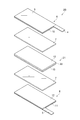
- FIG. 1 It is a perspective view which shows the secondary battery which concerns on one Embodiment. It is a disassembled perspective view which shows one Embodiment of the electrode group of the secondary battery shown in FIG. It is a schematic cross section which shows the manufacturing method of the battery member for secondary batteries which concerns on one Embodiment. It is a disassembled perspective view which shows one Embodiment of the electrode group of the secondary battery which concerns on a modification.
- a numerical range indicated by using “to” indicates a range including the numerical values described before and after “to” as the minimum value and the maximum value, respectively.
- the upper limit value or the lower limit value described in one numerical range may be replaced with the upper limit value or the lower limit value described in another stepwise description.
- the upper limit value or the lower limit value of the numerical range may be replaced with the values shown in the examples.
- FIG. 1 is a perspective view showing a secondary battery according to an embodiment.
- the secondary battery 1 includes an electrode group 2 composed of a positive electrode, a negative electrode, and an electrolyte layer, and a bag-shaped battery outer package 3 that houses the electrode group 2.
- a positive electrode current collecting tab 4 and a negative electrode current collecting tab 5 are provided on the positive electrode and the negative electrode, respectively.
- the positive electrode current collecting tab 4 and the negative electrode current collecting tab 5 protrude from the inside of the battery outer package 3 to the outside so that the positive electrode and the negative electrode can be electrically connected to the outside of the secondary battery 1, respectively.
- the battery outer package 3 may be formed of, for example, a laminate film.
- the laminate film may be a laminate film in which a resin film such as a polyethylene terephthalate (PET) film, a metal foil such as aluminum, copper, and stainless steel, and a sealant layer such as polypropylene are laminated in this order.
- PET polyethylene terephthalate
- metal foil such as aluminum, copper, and stainless steel
- sealant layer such as polypropylene
- FIG. 2 is an exploded perspective view showing an embodiment of the electrode group 2 of the secondary battery 1 shown in FIG.
- the electrode group 2A includes a positive electrode 6, an electrolyte layer 7, and a negative electrode 8 in this order.
- the positive electrode 6 includes a positive electrode current collector 9 and a positive electrode mixture layer 10 provided on the positive electrode current collector 9.
- a positive electrode current collector tab 4 is provided on the positive electrode current collector 9 of the positive electrode 6.
- the negative electrode 8 includes a negative electrode current collector 11 and a negative electrode mixture layer 12 provided on the negative electrode current collector 11.
- a negative electrode current collector tab 5 is provided on the negative electrode current collector 11 of the negative electrode 8.
- the electrode group 2A includes a first secondary battery battery member (positive electrode member) including the positive electrode current collector 9, the positive electrode mixture layer 10, and the electrolyte layer 7 in this order. You can see that.
- the electrode group 2A includes a second secondary battery battery member (negative electrode member) including the negative electrode current collector 11, the negative electrode mixture layer 12, and the electrolyte layer 7 in this order. You can also see it.
- the method for producing a battery member for a secondary battery (hereinafter sometimes simply referred to as “battery member”) according to each embodiment of the present invention is a method for producing the positive electrode member or the negative electrode member.
- FIG. 3 is a schematic cross-sectional view showing a method for manufacturing a battery member for a secondary battery according to an embodiment.
- an electrode active material is contained on one surface (main surface) 13a of the current collector 13 (positive electrode current collector 9 or negative electrode current collector 11).
- the electrode mixture intermediate layer 14 (positive electrode mixture intermediate layer or negative electrode mixture intermediate layer) is formed (electrode mixture intermediate layer forming step).
- the method of forming the electrode mixture intermediate layer 14 on the one surface 13a of the current collector 13 is as follows.
- the electrode mixture slurry is applied on the one surface 13a of the current collector 13. It is a method to do.
- the electrode mixture slurry is a slurry (positive electrode mixture slurry or negative electrode mixture slurry) in which the material contained in the positive electrode mixture layer 10 or the negative electrode mixture layer 12 is dispersed in a dispersion medium.
- the electrode mixture slurry of this embodiment contains at least an electrode active material (positive electrode active material or negative electrode active material) and a dispersion medium.
- the current collector 13 is the positive electrode current collector 9.
- the positive electrode current collector 9 may be a metal such as aluminum, titanium, or tantalum, or an alloy thereof. Since the positive electrode current collector 9 is light and has a high weight energy density, it is preferably aluminum or an alloy thereof.
- the thickness of the positive electrode current collector 9 may be 10 ⁇ m or more and may be 100 ⁇ m or less.
- the current collector 13 is the negative electrode current collector 11.
- the negative electrode current collector 11 may be a metal such as aluminum, copper, nickel, stainless steel, or an alloy thereof.
- the negative electrode current collector 11 is preferably aluminum or an alloy thereof because it is lightweight and has a high weight energy density.
- the negative electrode current collector 11 is preferably copper from the viewpoint of ease of processing into a thin film and cost.
- the thickness of the negative electrode current collector 11 may be 10 ⁇ m or more, and may be 100 ⁇ m or less.
- the electrode active material is a positive electrode active material.
- the positive electrode active material may be a lithium transition metal compound such as a lithium transition metal oxide or a lithium transition metal phosphate.
- the lithium transition metal oxide may be, for example, lithium manganate, lithium nickelate, lithium cobaltate, or the like.
- Lithium transition metal oxide is a part of transition metals such as Mn, Ni, Co, etc. contained in lithium manganate, lithium nickelate, lithium cobaltate, etc., one or more other transition metals, or A lithium transition metal oxide substituted with a metal element (typical element) such as Mg or Al may also be used. That is, the lithium transition metal oxide may be a compound represented by LiM 1 O 2 or LiM 1 O 4 (M 1 includes at least one transition metal).
- lithium transition metal oxides are Li (Co 1/3 Ni 1/3 Mn 1/3 ) O 2 , LiNi 1/2 Mn 1/2 O 2 , LiNi 1/2 Mn 3/2 O. It may be 4 mag.
- the lithium transition metal oxide is preferably a compound represented by the following formula (1).
- Lithium transition metal phosphates are LiFePO 4 , LiMnPO 4 , LiMn x M 3 1-x PO 4 (0.3 ⁇ x ⁇ 1, M 3 is Fe, Ni, Co, Ti, Cu, Zn, Mg and Zr) Or at least one element selected from the group consisting of:
- the positive electrode active material may be primary particles that are not granulated, or may be secondary particles that are granulated.
- the particle diameter of the positive electrode active material is adjusted to be equal to or less than the thickness of the positive electrode mixture layer 10.
- the coarse particles are removed in advance by sieving classification, wind classification, etc.
- a positive electrode active material having a diameter is selected.
- the average particle diameter of the positive electrode active material is preferably 0.1 ⁇ m or more, more preferably 1 ⁇ m or more.
- the average particle diameter of the positive electrode active material is preferably 30 ⁇ m or less, more preferably 25 ⁇ m or less.
- the average particle diameter of the positive electrode active material is the particle diameter (D 50 ) when the ratio (volume fraction) to the volume of the entire positive electrode active material is 50%.
- the average particle diameter (D 50 ) of the positive electrode active material is measured by suspending the positive electrode active material in water by a laser scattering method using a laser scattering particle size measuring device (for example, Microtrack). Can be obtained.
- the content of the positive electrode active material is 70% by mass or more, 80% by mass or more, or 90% based on the total amount of nonvolatile components in the positive electrode mixture slurry (a component obtained by removing the dispersion medium from the positive electrode mixture slurry; the same applies hereinafter). It may be not less than mass% and may be not more than 99 mass%. Thereby, content of the positive electrode active material in the positive electrode mixture layer obtained becomes content similar to content mentioned above.
- the electrode active material is a negative electrode active material.
- the negative electrode active material those commonly used in the field of energy devices can be used.
- Specific examples of the negative electrode active material include metal lithium, lithium titanate (Li 4 Ti 5 O 12 ), a lithium alloy or other metal compound, a carbon material, a metal complex, and an organic polymer compound. .
- the negative electrode active material may be one of these alone or a mixture of two or more.
- Carbon materials include natural graphite (flaky graphite, etc.), graphite such as artificial graphite, amorphous carbon, carbon fiber, acetylene black, ketjen black, channel black, furnace black, lamp black, thermal Examples thereof include carbon black such as black.
- the negative electrode active material may be silicon, tin, or a compound containing these elements (oxide, nitride, alloy with other metals). Good.
- the average particle diameter (D 50 ) of the negative electrode active material is preferably 1 ⁇ m or more from the viewpoint of obtaining a well-balanced negative electrode that suppresses an increase in irreversible capacity due to a decrease in particle diameter and has improved electrolyte salt retention ability. More preferably, it is 5 ⁇ m or more, more preferably 10 ⁇ m or more, preferably 50 ⁇ m or less, more preferably 40 ⁇ m or less, and further preferably 30 ⁇ m or less.
- the average particle diameter (D 50 ) of the negative electrode active material is measured by the same method as the average particle diameter (D 50 ) of the positive electrode active material described above.
- the content of the negative electrode active material is 60% by mass or more, 65% by mass or more, or 70% based on the non-volatile content in the negative electrode mixture slurry (a component obtained by removing the dispersion medium from the negative electrode mixture slurry; the same applies hereinafter). It may be not less than mass%, and may be not more than 99 mass%, not more than 95 mass%, or not more than 90 mass%. Thereby, content of the negative electrode active material in the obtained negative mix layer becomes content similar to content mentioned above.
- the dispersion medium may be water or an organic solvent.
- the organic solvent may be N-methyl-2-pyrrolidone (NMP), N, N-dimethylacetamide, methyl ethyl ketone, toluene, 2-butanol, cyclohexanone, ethyl acetate, 2-propanol, and preferably NMP.
- NMP N-methyl-2-pyrrolidone
- the content of the dispersion medium in the electrode mixture slurry is, for example, 20 parts by mass with respect to 100 parts by mass of the non-volatile content in the electrode mixture slurry (the component obtained by removing the dispersion medium from the electrode mixture slurry). It may be above and may be 1000 mass parts or less.
- the electrode mixture slurry may further contain a conductive agent, a binder and the like as other components.
- the electrode mixture intermediate layer 14 further containing these materials is formed.
- the conductive agent is not particularly limited, and may be a carbon material such as graphite, acetylene black, carbon black, or carbon fiber.
- the conductive agent may be a mixture of two or more carbon materials described above.
- the content of the conductive agent may be 1 to 70% by mass based on the total nonvolatile content in the electrode mixture slurry. Thereby, content of the electrically conductive agent in the electrode mixture layer obtained becomes content similar to content mentioned above.
- the binder is not particularly limited, but contains as a monomer unit at least one selected from the group consisting of ethylene tetrafluoride, vinylidene fluoride, hexafluoropropylene, acrylic acid, maleic acid, ethyl methacrylate, and methyl methacrylate. It may be a polymer, rubber such as styrene-butadiene rubber, isoprene rubber or acrylic rubber.
- the binder is preferably a copolymer containing hexafluoropropylene and vinylidene fluoride as structural units.
- the content of the binder may be 1 to 70% by mass based on the total nonvolatile content in the electrode mixture slurry. Thereby, content of the binder in the obtained electrode mixture layer becomes content similar to content mentioned above.
- the electrode mixture slurry may further contain an ionic liquid and an electrolyte salt described later, but preferably does not contain the ionic liquid and the electrolyte salt.
- examples of the method of applying the electrode mixture slurry include a method of applying using an applicator and a method of applying by spraying. By these methods, an electrode mixture slurry is applied onto one surface 13a of the current collector 13. As a result, as shown in FIG. 3A, the electrode mixture intermediate layer 14 is formed on the one surface 13 a of the current collector 13.
- the dispersion medium in the slurry may be volatilized. That is, the “electrode mixture intermediate layer” in this specification includes a layer formed of an electrode mixture slurry and a layer formed by volatilization of a part or all of the dispersion medium from the electrode mixture slurry. It is.
- the method of volatilizing the dispersion medium may be, for example, a method of drying by heating, a method of reducing pressure, a method of combining reduced pressure and heating, or the like. In the method of reducing the pressure, the pressure may be reduced to a vacuum state.
- the heating temperature for drying may be 50 to 150 ° C. The heating time may be changed depending on the temperature as long as the dispersion medium is sufficiently volatilized, but may be, for example, 1 minute to 48 hours.
- the oxide particles 16, the polymer 17, the surface of the electrode mixture intermediate layer 14 on the side opposite to the current collector 13, A slurry 15 containing an ionic liquid, an electrolyte salt, and a dispersion medium is applied.
- this slurry is also referred to as “electrolyte slurry”
- the step of applying the electrolyte slurry 15 is also referred to as “electrolyte slurry application step”.
- the oxide particles 16 are, for example, inorganic oxide particles.
- the inorganic oxide is an inorganic oxide containing, for example, Li, Mg, Al, Si, Ca, Ti, Zr, La, Na, K, Ba, Sr, V, Nb, B, Ge and the like as constituent elements. Good.
- the oxide particles 16 are preferably at least one selected from the group consisting of SiO 2 , Al 2 O 3 , AlOOH, MgO, CaO, ZrO 2 , TiO 2 , Li 7 La 3 Zr 2 O 12 , and BaTiO 3. Particles. Since the oxide particles 16 have polarity, it is possible to promote dissociation of the electrolyte in the electrolyte layer and improve battery characteristics.
- the oxide particles 16 may be rare earth metal oxides. Specifically, the oxide particles 16 are scandium oxide, yttrium oxide, lanthanum oxide, cerium oxide, praseodymium oxide, neodymium oxide, samarium oxide, eurobium oxide, gadolinium oxide, terbium oxide, dysprosium oxide, holmium oxide, erbium oxide, It may be thulium oxide, ytterbium oxide, lutetium oxide or the like.
- the oxide particles 16 may have a hydrophobic surface.
- the oxide particles usually have a hydroxyl group on the surface and tend to be hydrophilic.
- the oxide particles having a hydrophobic surface have fewer hydroxyl groups on the surface than the oxide particles having no hydrophobic surface. For this reason, when oxide particles having a hydrophobic surface are used, the affinity between the oxide particles and the ionic liquid is expected to improve because the ionic liquid is hydrophobic. Therefore, it is considered that the ionic liquid retention in the electrolyte layer 7 is further improved, and as a result, the ionic conductivity of the electrolyte layer 7 is improved.
- oxide particles having a hydrophobic surface are used, not only when the secondary battery is discharged at a relatively low current, but also the discharge characteristics when discharging at a relatively high current (for example, about 0.5 C) are improved. be able to.
- the oxide particles having a hydrophobic surface can be obtained by, for example, treating hydrophilic oxide particles with a surface treatment agent capable of imparting a hydrophobic surface. That is, the oxide particles having a hydrophobic surface mean oxide particles that have been surface-treated with a surface treatment agent.
- the surface treatment agent may be a silicon-containing compound.
- the oxide particles 16 may be surface-treated with a silicon-containing compound. That is, the oxide particle 16 may be one in which the surface of the oxide particle and the silicon atom of the silicon-containing compound are bonded via an oxygen atom.
- the silicon-containing compound is preferably at least one selected from the group consisting of halogen-containing alkylsilanes, alkoxysilanes, epoxy group-containing silanes, amino group-containing silanes, silazanes, and siloxanes.
- the halogen element in the halogen-containing alkylsilane may be chlorine, fluorine or the like.
- the halogen-containing alkylsilane (alkylchlorosilane) containing chlorine may be methyltrichlorosilane, dimethyldichlorosilane, trimethylchlorosilane, n-octyldimethylchlorosilane, or the like.
- the halogen-containing alkylsilane (fluoroalkylsilane) containing fluorine may be trifluoropropyltrimethoxysilane, tridecafluorooctyltrimethoxysilane, or the like.
- Alkoxysilanes are methyltrimethoxysilane, dimethyldimethoxysilane, phenyltrimethoxysilane, phenyltriethoxysilane, dimethoxydiphenylsilane, n-propyltrimethoxysilane, hexyltrimethoxysilane, tetraethoxysilane, methyltriethoxysilane, dimethyldi It may be ethoxysilane, n-propyltriethoxysilane, or the like.
- Epoxy group-containing silanes are 2- (3,4-epoxycyclohexyl) ethyltrimethoxysilane, 3-glycidoxypropylmethyldimethoxysilane, 3-glycidoxypropyltrimethoxysilane, 3-glycidoxypropylmethyldiethoxy. Silane, 3-glycidoxypropyltriethoxysilane and the like may be used.
- Amino group-containing silanes are N-2- (aminoethyl) -3-aminopropylmethyldimethoxysilane, N-2- (aminoethyl) -3-aminopropyltrimethoxysilane, 3-aminopropyltriethoxysilane, N- Phenyl-3-aminopropyltrimethoxysilane or the like may be used.
- Silazane may be hexamethyldisilazane or the like.
- Siloxane may be dimethyl silicone oil or the like.
- One or both of these terminals may have a reactive functional group (for example, a carboxyl group).
- oxide particles having a hydrophobic surface those produced by a known method may be used, or commercially available products may be used as they are.
- the oxide particles 16 generally include primary particles that integrally form a single particle (particles that do not constitute a secondary particle) and a plurality of primary particles, as determined from an apparent geometric form. Secondary particles formed by the aggregation of the particles may be included.
- the specific surface area of the oxide particles 16 is preferably 2 to 400 m 2 / g, 5 to 100 m 2 / g, 10 to 80 m 2 / g, or 15 to 60 m 2 / g.
- the specific surface area is 2 to 400 m 2 / g, the secondary battery including the electrolyte layer containing such oxide particles tends to have excellent discharge characteristics.
- the specific surface area of the oxide particles 16 may be 2 m 2 / g or more, 5 m 2 / g or more, 10 m 2 / g or more, 15 m 2 / g or more, or 50 m 2 / g or more, 400 m 2 / g or less, 350 m 2 / g or less, 300 m 2 / g or less, 200 m 2 / g or less, 100 m 2 / g or less, 90 m 2 / g or less, 80 m 2 / g or less, or 60 m 2 / g or less. May be.
- the specific surface area of the oxide particles 16 means the specific surface area of the whole oxide particles including primary particles and secondary particles, and is measured by the BET method.
- the average primary particle size of the oxide particles 16 (average particle size of the primary particles) is preferably 0.005 ⁇ m (5 nm) or more, more preferably 0.01 ⁇ m, from the viewpoint of improving the conductivity of the secondary battery 1. (10 nm) or more, more preferably 0.015 ⁇ m (15 nm) or more. From the viewpoint of making the electrolyte layer 7 thin, the average primary particle size of the oxide particles 16 is preferably 1 ⁇ m or less, more preferably 0.1 ⁇ m or less, and even more preferably 0.05 ⁇ m or less. The average primary particle size of the oxide particles 16 can be measured by observing the oxide particles 16 with a transmission electron microscope or the like.
- the average particle diameter of the oxide particles 16 is preferably 0.005 ⁇ m or more, more preferably 0.01 ⁇ m or more, and further preferably 0.03 ⁇ m or more.
- the average particle size of the oxide particles 16 is preferably 5 ⁇ m or less, more preferably 3 ⁇ m or less, and even more preferably 1 ⁇ m or less.
- the average particle diameter of the oxide particles 16 is measured by a laser diffraction method, and corresponds to the particle diameter at which the volume accumulation is 50% when the volume accumulation particle size distribution curve is drawn from the small particle diameter side.
- the content of the oxide particles 16 is preferably 1% by mass or more, more preferably 3% by mass based on the total amount of nonvolatile components in the electrolyte slurry 15 (a component obtained by removing the dispersion medium from the electrolyte slurry; the same applies hereinafter). % Or more, more preferably 5% by mass or more, particularly preferably 7% by mass or more, preferably 30% by mass or less, more preferably 27% by mass or less, and further preferably 25% or less. It is below mass%.
- the content of the oxide particles 16 is preferably 5% by volume or more, more preferably 7% by volume or more, and still more preferably 9% by volume, based on the total nonvolatile content in the electrolyte slurry 15. % Or more, preferably 20% by volume or less, more preferably 17% by volume or less, and still more preferably 15% by volume or less.
- Polymer 17 preferably has a first structural unit selected from the group consisting of ethylene tetrafluoride and vinylidene fluoride.
- the polymer 17 is preferably one or more kinds of polymers, and among the structural units constituting the one or more kinds of polymers, the first structural unit described above, hexafluoropropylene, acrylic A second structural unit selected from the group consisting of acid, maleic acid, ethyl methacrylate, and methyl methacrylate may be included. That is, the first structural unit and the second structural unit may be included in one kind of polymer to form a copolymer, and each of the first structural unit and the second structural unit may be included in another polymer and have the first structural unit. And at least two types of polymers, the second polymer having the second structural unit.
- the polymer 17 may be polytetrafluoroethylene, polyvinylidene fluoride, a copolymer of vinylidene fluoride and hexafluoropropylene, or the like.
- the content of the polymer 17 is preferably 3% by mass or more, preferably 60% by mass or less, more preferably 50% by mass or less, based on the total nonvolatile content in the electrolyte slurry 15. More preferably, it is 40 mass% or less.
- the ionic liquid contains the following anion component and cation component. Note that the ionic liquid in this specification is a liquid substance at ⁇ 20 ° C. or higher. In the secondary battery 1, the types of ionic liquids contained in the positive electrode member and the negative electrode member may be the same or different.
- the anion component of the ionic liquid is not particularly limited, but is an anion of a halogen such as Cl ⁇ , Br ⁇ and I ⁇ , an inorganic anion such as BF 4 ⁇ and N (SO 2 F) 2 — , B (C 6 H 5 ) 4 ⁇ , CH 3 SO 2 O ⁇ , CF 3 SO 2 O ⁇ , N (SO 2 C 4 F 9 ) 2 ⁇ , N (SO 2 CF 3 ) 2 ⁇ , N (SO 2 C 2 F 5 ) 2 ⁇ Or an organic anion.
- the anionic component of the ionic liquid preferably contains at least one anionic component represented by the following formula (2).
- Examples of the anion component represented by the formula (2) include N (SO 2 C 4 F 9 ) 2 ⁇ , N (SO 2 F) 2 ⁇ , N (SO 2 CF 3 ) 2 — and N (SO 2 C 2 F 5 ) 2 — .
- the anionic component of the ionic liquid is more preferably N (SO 2 C 4 F 9 ) 2 ⁇ , CF 3 SO from the viewpoint of further improving the ionic conductivity with a relatively low viscosity and further improving the charge / discharge characteristics. It contains at least one selected from the group consisting of 2 O ⁇ , N (SO 2 F) 2 ⁇ , N (SO 2 CF 3 ) 2 ⁇ , and N (SO 2 C 2 F 5 ) 2 — .
- the electrolyte slurry 15 more preferably contains N (SO 2 F) 2 — as an anion component.
- N (SO 2 F) 2 — is contained as an anion component, a good interface can be formed between the electrode mixture layer and the electrolyte layer in the obtained battery member. This effect is particularly remarkable in the negative electrode member. That is, in the method for producing a negative electrode member, the ionic liquid contained in the electrolyte slurry preferably contains N (SO 2 F) 2 — as an anion component.
- the cation component of the ionic liquid is preferably at least one selected from the group consisting of a chain quaternary onium cation, a piperidinium cation, a pyrrolidinium cation, a pyridinium cation, and an imidazolium cation.
- the chain quaternary onium cation is, for example, a compound represented by the following formula (3).
- R 1 to R 4 each independently represents a chain alkyl group having 1 to 20 carbon atoms, or a chain alkoxyalkyl group represented by R—O— (CH 2 ) n —.
- R represents a methyl group or an ethyl group, and n represents an integer of 1 to 4
- X represents a nitrogen atom or a phosphorus atom.
- the number of carbon atoms of the alkyl group represented by R 1 to R 4 is preferably 1 to 20, more preferably 1 to 10, and still more preferably 1 to 5.
- the piperidinium cation is, for example, a nitrogen-containing six-membered cyclic compound represented by the following formula (4).
- R 5 and R 6 are each independently an alkyl group having 1 to 20 carbon atoms or an alkoxyalkyl group represented by R—O— (CH 2 ) n — (R is methyl And n represents an integer of 1 to 4.
- the number of carbon atoms of the alkyl group represented by R 5 and R 6 is preferably 1 to 20, more preferably 1 to 10, and still more preferably 1 to 5.
- the pyrrolidinium cation is, for example, a five-membered cyclic compound represented by the following formula (5).
- R 7 and R 8 are each independently an alkyl group having 1 to 20 carbon atoms or an alkoxyalkyl group represented by R—O— (CH 2 ) n — (R is methyl And n represents an integer of 1 to 4.
- the carbon number of the alkyl group represented by R 7 and R 8 is preferably 1-20, more preferably 1-10, and still more preferably 1-5.
- the pyridinium cation is, for example, a compound represented by the following formula (6).
- R 9 to R 13 each independently represents an alkyl group having 1 to 20 carbon atoms, an alkoxyalkyl group represented by R—O— (CH 2 ) n — (R represents a methyl group) Or an ethyl group, and n represents an integer of 1 to 4), or a hydrogen atom.
- the number of carbon atoms of the alkyl group represented by R 9 to R 13 is preferably 1 to 20, more preferably 1 to 10, and still more preferably 1 to 5.
- the imidazolium cation is, for example, a compound represented by the following formula (7).
- R 14 to R 18 are each independently an alkyl group having 1 to 20 carbon atoms, an alkoxyalkyl group represented by R—O— (CH 2 ) n — (R is a methyl group) Or an ethyl group, and n represents an integer of 1 to 4), or a hydrogen atom.
- the number of carbon atoms of the alkyl group represented by R 14 to R 18 is preferably 1 to 20, more preferably 1 to 10, and still more preferably 1 to 5.
- the ionic liquid contained in the electrolyte slurry 15 is preferably N, N-diethyl-N-methyl-N- (2-methoxyethyl) ammonium-bis (trifluoromethanesulfonyl) imide (DEME-TFSI), N, N— Diethyl-N-methyl-N- (2-methoxyethyl) ammonium-bis (fluorosulfonyl) imide (DEME-FSI), 1-ethyl-3-methylimidazolium-bis (trifluoromethanesulfonyl) imide (EMI-TFSI) 1-ethyl-3-methylimidazolium-bis (fluorosulfonyl) imide (EMI-FSI), N-methyl-N-propylpyrrolidinium-bis (trifluoromethanesulfonyl) imide (Py13-TFSI), N-methyl -N-propylpyrrolidinium-bis (triflu
- the ionic liquid contained in the electrolyte slurry 15 is more preferably DEME-FSI, EMI-FSI, Py13-FSI, or Py12-FSI from the viewpoint of further improving the discharge characteristics at a relatively high current.
- the ionic liquid contained in the electrolyte slurry 15 is more preferably EMI-FSI from the viewpoint of further improving the discharge characteristics at a relatively high current.
- the electrolyte salt may be at least one selected from the group consisting of a lithium salt, a sodium salt, a calcium salt, and a magnesium salt.
- the anion component of the electrolyte salt includes halide ions (I ⁇ , Cl ⁇ , Br ⁇ etc.), SCN ⁇ , BF 4 ⁇ , BF 3 (CF 3 ) ⁇ , BF 3 (C 2 F 5 ) ⁇ , PF 6 ⁇ .
- the anion component of the electrolyte salt is preferably an anion component represented by the above formula (2) such as N (SO 2 F) 2 ⁇ , N (SO 2 CF 3 ) 2 — , PF 6 ⁇ , BF 4 ⁇ . , B (O 2 C 2 O 2 ) 2 ⁇ , or ClO 4 — .
- Lithium salts include LiPF 6 , LiBF 4 , Li [FSI], Li [TFSI], Li [f 3 C], Li [BOB], LiClO 4 , LiBF 3 (CF 3 ), LiBF 3 (C 2 F 5 ), LiBF 3 (C 3 F 7 ), LiBF 3 (C 4 F 9 ), LiC (SO 2 CF 3 ) 3 , LiCF 3 SO 2 O, LiCF 3 COO, and LiRCOO (R is an alkyl group having 1 to 4 carbon atoms) , A phenyl group, or a naphthyl group).
- Sodium salts include NaPF 6 , NaBF 4 , Na [FSI], Na [TFSI], Na [f 3 C], Na [BOB], NaClO 4 , NaBF 3 (CF 3 ), NaBF 3 (C 2 F 5 ), NaBF 3 (C 3 F 7 ), NaBF 3 (C 4 F 9 ), NaC (SO 2 CF 3 ) 3 , NaCF 3 SO 2 O, NaCF 3 COO, and NaRCOO (R is an alkyl group having 1 to 4 carbon atoms) , A phenyl group, or a naphthyl group).
- the calcium salts are Ca (PF 6 ) 2 , Ca (BF 4 ) 2 , Ca [FSI] 2 , Ca [TFSI] 2 , Ca [f3C] 2 , Ca [BOB] 2 , Ca (ClO 4 ) 2 , Ca [BF 3 (CF 3 )] 2 , Ca [BF 3 (C 2 F 5 )] 2 , Ca [BF 3 (C 3 F 7 )] 2 , Ca [BF 3 (C 4 F 9 )] 2 , Ca [C (SO 2 CF 3 ) 3 ] 2 , Ca (CF 3 SO 2 O) 2 , Ca (CF 3 COO) 2 , and Ca (RCOO) 2 (R is an alkyl group having 1 to 4 carbon atoms, phenyl Or at least one selected from the group consisting of a naphthyl group).
- Magnesium salts are Mg (PF 6 ) 2 , Mg (BF 4 ) 2 , Mg [FSI] 2 , Mg [TFSI] 2 , Mg [f 3 C] 2 , Mg [BOB] 2 , Mg (ClO 4 ) 2 , Mg [BF 3 (CF 3 )] 2 , Mg [BF 3 (C 2 F 5 )] 2 , Mg [BF 3 (C 3 F 7 )] 2 , Mg [BF 3 (C 4 F 9 )] 2 , Mg [C (SO 2 CF 3 ) 3 ] 2 , Mg (CF 3 SO 3 ) 2 , Mg (CF 3 COO) 2 , and Mg (RCOO) 2 (R is an alkyl group having 1 to 4 carbon atoms, a phenyl group Or a naphthyl group) may be at least one selected from the group consisting of:
- the electrolyte salt is preferably LiPF 6 , LiBF 4 , Li [FSI], Li [TFSI], Li [f 3 C], Li [BOB], LiClO 4.
- LiBF 3 (CF 3 ), LiBF 3 (C 2 F 5 ), LiBF 3 (C 3 F 7 ), LiBF 3 (C 4 F 9 ), LiC (SO 2 CF 3 ) 3 , LiCF 3 SO 2 O It is at least one selected from the group consisting of LiCF 3 COO and LiRCOO (where R is an alkyl group having 1 to 4 carbon atoms, a phenyl group, or a naphthyl group), more preferably Li [TFSI], Li [FSI], LiPF 6, LiBF 4, Li [BOB], and at least one selected from the group consisting of LiClO 4, more preferably Li [TF I], and is one selected from the group consisting of Li [FSI].
- the electrolyte slurry may contain an ionic liquid and an electrolyte salt as an “ionic liquid electrolytic solution” in which the electrolyte salt is dissolved in the ionic liquid.
- the salt concentration of the electrolyte salt per unit volume of the ionic liquid is preferably greater than 0.5 mol / L.
- the salt concentration of the electrolyte salt per unit volume of the ionic liquid is more preferably 0.7 mol / L or more, and further preferably 1.0 mol / L or more.
- the salt concentration of the electrolyte salt per unit volume of the ionic liquid is preferably 3.0 mol / L or less, more preferably 2. mol / L or less, from the viewpoint of suppressing a decrease in ionic conductivity due to excessive inclusion of the electrolyte salt. 7 mol / L or less, more preferably 2.5 mol / L or less.
- the content of the ionic liquid electrolyte (the total content of the ionic liquid and the electrolyte salt) is determined in view of obtaining a uniform dispersion state in the electrolyte slurry 15, and the electrode mixture layer (the positive electrode mixture layer 10 or the negative electrode mixture layer). 12) From the viewpoint of satisfactorily forming the interface between the electrolyte layer 7, it is preferably 20% by mass or more, more preferably 25% by mass or more, and still more preferably, based on the total nonvolatile content in the electrolyte slurry 15. 30% by mass or more. Thereby, the ionic conductivity of the electrolyte layer 7 can be raised and the battery characteristic of a secondary battery can be improved further.
- the content of the ionic liquid electrolytic solution may be 90% by mass or less, 85% by mass or less, or 80% by mass or less based on the total nonvolatile content in the electrolyte slurry 15.
- the content of the ionic liquid electrolytic solution (the total content of the ionic liquid and the electrolyte salt) is determined in view of obtaining a uniform dispersion state in the electrolyte slurry 15, and the electrode mixture layer (the positive electrode mixture layer 10).
- it is preferably 35% by volume or more, more preferably 40% by volume or more, based on the total nonvolatile content in the electrolyte slurry 15. Yes, more preferably 45% by volume or more.
- the content of the ionic liquid electrolytic solution may be 90% by volume or less, 85% by volume or less, or 80% by volume or less based on the total nonvolatile content in the electrolyte slurry 15.
- the dispersion medium in the electrolyte slurry 15 may be the same as the dispersion medium used for the electrode mixture slurry described above.
- the content of the dispersion medium in the electrolyte slurry 15 may be, for example, 5 parts by mass or more and 1000 parts by mass or less with respect to 100 parts by mass of the non-volatile content in the electrolyte slurry 15.
- the ratio of the total content of the ionic liquid and the electrolyte salt to the content of the oxide particles 16 is larger than 4/1 by volume ratio (volume of the ionic liquid electrolyte / volume of the oxide particles). / Less than 1.
- the ratio of the total content of the ionic liquid and the electrolyte salt to the content of the oxide particles 16 is preferably 5/1 or more, and more preferably. Is 6/1 or more.
- the ratio of the total salt content is, in volume ratio, preferably 11/1 or less, more preferably 10/1 or less, still more preferably 9/1 or less, and particularly preferably 8/1 or less. It is.
- the ratio of the content of the oxide particles 16 to the content of the polymer 17 is preferably a mass ratio (content of oxide particles / content of polymer) from the viewpoint of improving the strength of the electrolyte layer. Is 1/5 or more, more preferably 1/4 or more, still more preferably 1/3 or more, and particularly preferably 1/2 or more. From the viewpoint of improving the discharge characteristics at a relatively high current, the ratio of the content of the oxide particles 16 to the content of the polymer 17 is preferably 5/1 or less, more preferably 3/1, from the viewpoint of improving the discharge characteristics at a relatively high current. Or less, more preferably 1/1 or less, and particularly preferably 2/3 or less.
- the method of applying the electrolyte slurry 15 on the one surface (main surface) 14a of the electrode mixture intermediate layer 14 is a method of applying the electrode mixture slurry described above on the one surface 13a of the current collector 13. It may be the same.
- the method of applying the electrolyte slurry 15 may be the same as or different from the method of applying the electrode mixture slurry.
- the dispersion medium contained in the electrode mixture intermediate layer 14 and the electrolyte slurry 15 is volatilized.
- the method for volatilizing the dispersion medium may be the same as the method for volatilizing the dispersion medium in the electrode mixture slurry described above.
- the current collector 13, the electrode mixture layer 18 (the positive electrode mixture layer 10 or the negative electrode mixture layer). 12) and the battery member 19 for a secondary battery (positive electrode member or negative electrode member) including the electrolyte layer 7 in this order can be obtained.
- the secondary battery using the battery member 19 obtained by the manufacturing method of the present embodiment is particularly excellent in discharge characteristics when the secondary battery is discharged at a relatively low current.
- the electrolyte slurry 15 when the electrolyte slurry 15 is applied on the electrode mixture intermediate layer 14, as shown by the arrow in FIG.
- the slurry moves from the slurry 15 to the electrode mixture intermediate layer 14. This movement is presumed to be based on the action of reducing the concentration difference of the ionic liquid electrolyte solution between the electrode mixture intermediate layer 14 and the electrolyte slurry 15, the action of gravity, or the capillary phenomenon.
- the electrolyte layer 7 is formed by applying the electrolyte slurry 15 on the electrode mixture intermediate layer 14, there are fine irregularities on the surface of the electrode mixture intermediate layer 14. Also, the electrolyte slurry 15 is arranged so as to fill the recess and flatten it. As a result, in the obtained battery member 19, a good interface is formed in which the electrode mixture layer 18 and the electrolyte layer 7 are closely adhered. In the battery member 19, since the ionic liquid electrolyte can move between the electrolyte slurry 15 and the electrode mixture intermediate layer 14 in the electrolyte slurry coating step, the ionic liquid electrolyte is contained in the electrode mixture layer 18. Tends to exist around the electrode active material. Therefore, in the battery member 19, the electrode active material / electrolyte interface is satisfactorily formed.
- the electrode mixture layer 18 / electrolyte layer 7 interface is well formed and has excellent adhesion, and the electrode active material / electrolyte interface is also well formed. The Therefore, the secondary battery using this battery member 19 is further excellent in battery characteristics.
- a method for manufacturing a secondary battery includes a step of infiltrating a solution (polymer solution) containing a polymer into the electrode mixture intermediate layer 14 before applying the electrolyte slurry 15 (polymer solution infiltration). Step) may be further provided.
- the polymer solution contains a polymer having a structural unit represented by the following formula (8), an ionic liquid, and an electrolyte salt.
- X ⁇ represents a counter anion.
- X ⁇ include BF 4 ⁇ (tetrafluoroborate anion), PF 6 ⁇ (hexafluorophosphate anion), [FSI] ⁇ , [TFSI] ⁇ , [f3C] ⁇ , [BOB] ⁇ , and BF.
- X ⁇ is preferably at least one selected from the group consisting of BF 4 ⁇ , PF 6 ⁇ , [FSI] ⁇ , [TFSI] ⁇ , and [f3C] ⁇ , more preferably [TFSI] ⁇ . Or [FSI] ⁇ .
- the viscosity average molecular weight Mv (g ⁇ mol ⁇ 1 ) of the polymer having the structural unit represented by the formula (8) is not particularly limited, but is preferably 1.0 ⁇ 10 5 or more, more preferably 3.0. ⁇ 10 5 or more.
- the viscosity average molecular weight of the polymer is preferably 5.0 ⁇ 10 6 or less, and more preferably 1.0 ⁇ 10 6 .
- the handling property when penetrating the polymer solution tends to be further increased.
- the “viscosity average molecular weight” can be evaluated by a viscosity method which is a general measurement method. For example, from the intrinsic viscosity [ ⁇ ] measured based on JIS K 7367-3: 1999. Can be calculated.
- the polymer having the structural unit represented by the formula (8) is preferably a polymer consisting only of the structural unit represented by the formula (8), that is, a homopolymer, from the viewpoint of ion conductivity.
- the polymer having the structural unit represented by the formula (8) may be a polymer represented by the following formula (8A).
- n 300 to 4000
- Y ⁇ represents a counter anion.
- Y ⁇ those similar to those exemplified for X ⁇ can be used.
- N is 300 or more, preferably 400 or more, more preferably 500 or more, and may be 4000 or less, preferably 3500 or less, more preferably 3000 or less.
- n is 300 to 4000, preferably 400 to 3500, more preferably 500 to 3000.
- the production method of the polymer having the structural unit represented by the formula (8) is not particularly limited, and for example, the production method described in Journal of Power Sources 2009, 188, 558-563 can be used.
- poly (diallyldimethylammonium) chloride [P (DADMA)] [Cl]
- P (DADMA)] [Cl] poly (diallyldimethylammonium) chloride
- a commercially available product can be used as it is.
- Li [TFSI] is dissolved in deionized water to prepare an aqueous solution containing Li [TFSI].
- the molar ratio of Li [TFSI] to [P (DADMA)] [Cl] (molar amount of Li [TFSI] / molar amount of [P (DADMA)] [Cl]) was 1.2 to 2.0.
- the two aqueous solutions are mixed and stirred for 2 to 8 hours to precipitate a solid, and the obtained solid is collected by filtration.
- the polymer ([P (DADMA)] [TFSI]) having the structural unit represented by the formula (8) can be obtained by washing the solid with deionized water and vacuum-drying for 12 to 48 hours. .
- the polymer having the structural unit represented by the formula (8) is preferably 10% by mass or more, more preferably 20% by mass or more, and further preferably 30% by mass or more, based on the total amount of the polymer solution. Moreover, it is preferably 80% by mass or less, more preferably 75% by mass or less, and further preferably 70% by mass or less.
- the ionic liquid and electrolyte salt contained in the polymer solution may be the same as the ionic liquid and electrolyte salt that can be used in the above-described embodiment.
- the ionic liquid and electrolyte salt contained in the polymer solution may be the same as or different from the ionic liquid and electrolyte salt contained in the electrolyte slurry 15.
- the ionic liquid and the electrolyte salt may be added to the polymer solution as an ionic liquid electrolytic solution.
- the salt concentration of the electrolyte salt per unit volume of the ionic liquid may be 0.3 mol / L or more, 0.5 mol / L or more, or 1.0 mol / L or more. It may be 0.0 mol / L or less, 2.7 mol / L or less, or 2.5 mol / L or less.
- the content of the ionic liquid electrolytic solution is preferably 3% by mass or more, more preferably 5% by mass or more, still more preferably 10% by mass or more, and preferably 80% based on the total amount of the polymer solution. It is not more than mass%, more preferably not more than 75 mass%, still more preferably not more than 70 mass%.
- the polymer solution may further contain a dispersion medium.
- the dispersion medium may be an organic solvent, such as acetone, ethyl methyl ketone, ⁇ -butyrolactone, and the like.
- the polymer solution infiltration step the polymer solution is infiltrated into the electrode mixture intermediate layer 14 by, for example, a method of applying the polymer solution on the surface 14a of the electrode mixture intermediate layer 14 opposite to the current collector 13. is there.
- the application may be application by an applicator, application by spraying, or the like.
- the polymer solution applied on the electrode mixture intermediate layer 14 penetrates into the electrode mixture intermediate layer 14 to form an electrode mixture intermediate layer containing a polymer having a structural unit represented by the formula (8).
- the method of allowing the polymer solution to penetrate into the electrode mixture intermediate layer 14 may be, for example, a method of immersing the current collector 13 on which the electrode mixture intermediate layer 14 is formed in the polymer solution.
- an electrolyte slurry 15 is applied on the surface 14a opposite to the current collector 13 of the electrode mixture intermediate layer 14 (electrode mixture intermediate layer infiltrated with the polymer solution). (Electrolyte slurry coating process).
- the composition and application method of the electrolyte slurry 15 may be the same as those in the above-described embodiment.
- the polymer represented by the above-described formula (8) is included in the electrode mixture layer 18.
- the ionic conductivity of the electrode mixture layer 18 can be increased, and the battery characteristics of the secondary battery using the battery member 19 can be further improved.
- the secondary battery including the battery member manufactured by the above-described manufacturing method can take various modifications.
- FIG. 4 is an exploded perspective view showing an embodiment of an electrode group of a secondary battery according to a modification.
- the electrode group 2 ⁇ / b> B includes the bipolar electrode 21. That is, as shown in FIG. 4, the electrode group 2 ⁇ / b> B includes a positive electrode 6, a first electrolyte layer 7, a bipolar electrode 21, a second electrolyte layer 7, and a negative electrode 8 in this order.
- the bipolar electrode 21 includes a bipolar current collector 22, a positive electrode mixture layer 10 provided on a surface (positive electrode surface) on the negative electrode 8 side of the bipolar current collector 22, and a surface on the positive electrode 6 side of the bipolar current collector 22 ( And a negative electrode mixture layer 12 provided on the negative electrode surface).
- This bipolar secondary battery includes a first electrolyte layer 7, a positive electrode mixture layer 10, a bipolar current collector 22, a negative electrode mixture layer 12, and a second electrolyte layer 7 in this order. It can be seen that a battery battery member (bipolar electrode member) is included.
- the battery member manufacturing method according to an embodiment of the present invention is a method of manufacturing this bipolar electrode member.
- the method of manufacturing a bipolar electrode member includes a step of forming a positive electrode mixture intermediate layer on one surface (one main surface) of the bipolar current collector 22 (positive electrode mixture intermediate layer forming step); A step of applying a first electrolyte slurry on the surface of the positive electrode mixture intermediate layer opposite to the bipolar current collector 22 (first electrolyte slurry applying step), and the other surface (the other side) of the bipolar current collector 22 Of the negative electrode mixture intermediate layer on the surface of the negative electrode mixture intermediate layer opposite to the bipolar current collector 22, and a second electrolyte slurry. And a step of applying (second electrolyte slurry applying step).
- Each process may be implemented by the same material and method as each process (electrode mixture intermediate layer forming process, electrolyte slurry coating process) in each embodiment described above.
- the composition of the first electrolyte slurry and the second electrolyte slurry may be the same composition or different compositions, but is preferably the same composition.
- a solution containing a polymer having a structural unit represented by the above formula (8) is infiltrated into the positive electrode mixture intermediate layer or the negative electrode mixture intermediate layer.
- a step may be further provided.
- the polymer solution infiltration step may be performed by the same material and method as the polymer solution infiltration step in the above-described embodiment.
- the positive electrode mixture intermediate layer and the first electrolyte slurry dispersion medium are volatilized.
- the dispersion medium of the negative electrode mixture intermediate layer and the second electrolyte slurry is volatilized.
- the method for volatilizing the dispersion medium may be the same as the method in the above-described embodiment.
- a battery member for a secondary battery comprising the first electrolyte layer 7, the positive electrode mixture layer 10, the bipolar current collector 22, the negative electrode mixture layer 12, and the second electrolyte layer 7 in this order. (Bipolar electrode member) can be obtained.
- the electrolyte layer 7 As a second modification, in the battery member manufacturing method according to each of the above-described embodiments, after the electrolyte layer 7 is formed, another electrolyte layer (second electrolyte layer) is formed on the electrolyte layer (first electrolyte layer) 7.
- the step of laminating the electrolyte layer) may be further provided.
- the first electrolyte layer plays a role in favorably forming the interface between the electrode mixture layer and the second electrolyte layer, the first electrolyte layer can also be called an interface forming layer.
- a secondary battery using a battery member obtained by this manufacturing method includes a positive electrode current collector, a positive electrode mixture layer, a first interface forming layer, an electrolyte layer (second electrolyte layer), a second electrode group as an electrode group.
- An interface forming layer, a negative electrode mixture layer, and a negative electrode current collector are provided in this order.
- the electrode group includes a first battery member (positive electrode member) including a positive electrode current collector, a positive electrode mixture layer, a first interface forming layer, and an electrolyte layer in this order. You can see that.
- the electrode group includes a second battery member (negative electrode member) including a negative electrode current collector, a negative electrode mixture layer, a second interface forming layer, and an electrolyte layer in this order. Can also be seen.
- the manufacturing method according to the second modification is a manufacturing method of the positive electrode member and the negative electrode member.
- the interface forming layer may have the same composition as the electrolyte layer in the battery member of each embodiment described above. That is, the manufacturing method according to this modification is a method in which the electrolyte layer is replaced with the interface forming layer in each of the above-described embodiments.
- the battery member can be manufactured by disposing the electrolyte layer on the surface on the first interface forming layer side of the positive electrode member or on the surface of the negative electrode member on the second interface forming layer side.
- the electrolyte layer at this time may be one in which the electrolyte slurry 15 described above is formed in a sheet shape. That is, a base material such as a resin film is prepared, and the electrolyte slurry 15 is applied on the base material, and then the dispersion medium is volatilized to prepare an electrolyte sheet. And an electrolyte layer can be obtained by peeling a base material from this electrolyte sheet.
- the electrolyte layer may have a composition different from that of the electrolyte layer produced from the electrolyte slurry 15, for example, a known electrolyte composition such as an organic polymer solid electrolyte or an inorganic solid electrolyte. May be previously formed into a sheet shape.
- a known electrolyte composition such as an organic polymer solid electrolyte or an inorganic solid electrolyte. May be previously formed into a sheet shape.
- the organic polymer solid electrolyte may be polyethylene oxide or the like
- the inorganic solid electrolyte may be Li 7 La 3 Zr 2 O 12 , Li 6.75 La 3 Zr 1.75 Nb 0.25 O 12 (LLZ— Nb), Li 6.75 La 3 Zr 1.75 Ta 0.25 O 12 , Li 1 + c + d Al c (Ti, Ge) 2-c Si d P 3-d O 12 (where 0 ⁇ c ⁇ 2 Yes, 0 ⁇ d ⁇ 3, where (Ti, Ge) means either Ti or Ge, or both Ti and Ge.), Li 10 GeP 2 S 12 , Li 9.54 Si 1.74 P 1.44 S 11.7 Cl 0.3 or the like.
- the discharge characteristics of the secondary battery when discharged at a relatively low current can be improved. Furthermore, when the ionic liquid electrolyte is included in the interface forming layer, ionic conduction between the interface forming layer and the electrolyte layer becomes easier. As a result, the secondary battery using the battery member according to this modification has excellent battery characteristics because it can be said that the interface between the layers is well formed.
- composition of an ionic liquid ionic liquid electrolytic solution
- concentration of electrolyte salt / type of electrolyte salt / type of ionic liquid it may be expressed as “concentration of electrolyte salt / type of electrolyte salt / type of ionic liquid”.
- Example 1 [Production of positive electrode member] 92.5 parts by mass of layered lithium / nickel / manganese / cobalt composite oxide (positive electrode active material) and acetylene black (conductive agent, product name: HS-100, average particle size 48 nm, manufactured by Denka Corporation) 2.5 A positive electrode mixture prepared by dispersing 5 parts by mass of a copolymer part (solid content: 12% by mass) of vinylidene fluoride and hexafluoropropylene in an appropriate amount of N-methyl-2-pyrrolidone (NMP) as a dispersion medium. A slurry was prepared.
- NMP N-methyl-2-pyrrolidone
- This positive electrode mixture slurry was applied onto a positive electrode current collector (aluminum foil having a thickness of 20 ⁇ m) at a coating amount of 125 g / m 2 , heated at 80 ° C. for 12 hours, dried, and pressed, whereby the mixture was obtained.
- a positive electrode mixture intermediate layer having a density of 2.7 g / cm 3 was formed. This was cut into a width of 30 mm and a length of 45 mm, and then a positive electrode current collecting tab was attached.
- the content of SiO 2 particles was 9% by volume and the content of the ionic liquid electrolyte was 70% by volume, based on the total amount of nonvolatile content of the electrolyte slurry.
- the obtained electrolyte slurry was applied on the surface of the positive electrode mixture intermediate layer opposite to the positive electrode current collector, and heated at 80 ° C. for 12 hours to volatilize the dispersion medium to form an electrolyte layer. Thereby, the positive electrode member provided with a positive electrode collector, a positive mix layer, and an electrolyte layer in this order was obtained.
- the thickness of the electrolyte layer in the obtained positive electrode member was 15 ⁇ 2 ⁇ m.
- This negative electrode mixture slurry was coated on a current collector (copper foil having a thickness of 10 ⁇ m) at a coating amount of 60 g / m 2 , heated at 80 ° C. for 12 hours, dried, and pressed to obtain a mixture density.
- a negative electrode mixture intermediate layer of 1.8 g / cm 3 was formed. This was cut into a width of 31 mm and a length of 46 mm, and then a negative electrode current collecting tab was attached.
- the dispersion medium is volatilized to form an electrolyte layer by the same method as the positive electrode member manufacturing method. It was. Thereby, the negative electrode member provided with the negative electrode current collector, the negative electrode mixture layer, and the electrolyte layer in this order was obtained.
- the thickness of the electrolyte layer in the obtained negative electrode member was 15 ⁇ 2 ⁇ m.
- the produced positive electrode member and negative electrode member were laminated so that the respective electrolyte layers were in contact with each other, thereby producing an electrode group.
- this electrode group was housed in a battery exterior body made of an aluminum laminate film.
- the positive electrode current collection tab and the negative electrode current collection tab were taken out to seal the opening of the battery container, thereby producing a lithium ion secondary battery.
- the aluminum laminate film is a laminate of polyethylene terephthalate (PET) film / aluminum foil / sealant layer (polypropylene, etc.).
- PET polyethylene terephthalate
- the designed capacity of the produced lithium ion secondary battery was 20 mAh.
- Examples 2 to 22 Reference Examples 1 and 2> A lithium ion secondary battery was produced in the same manner as in Example 1 except that the composition of the electrolyte slurry was changed to that shown in Table 1 in the production of the positive electrode member and the negative electrode member.
- the oxide particles that are surface-treated with an average primary particle size of 40 nm are the same SiO 2 particles as in Example 1, and the average primary particle size is 40 nm and the surface treatment is not performed.
- the one is AEROSIL OX50 (product name) manufactured by Nippon Aerosil Co., Ltd., and the one having an average primary particle size of 7 nm is S5130 (product name) manufactured by SIGMA-ALDRICH.
- Discharge capacity retention rate (%) (discharge capacity at current value 0.2 C or 0.5 C / discharge capacity at current value 0.1 C) ⁇ 100
Abstract
Un aspect de la présente invention concerne un procédé de production d'un élément de batterie pour des batteries secondaires, qui comprend : une étape consistant à former une couche intermédiaire de mélange d'électrode, qui contient un matériau actif d'électrode, sur une surface d'un collecteur ; et une étape d'application d'une bouillie, qui contient des particules d'oxyde, un polymère, un liquide ionique et un sel d'électrolyte, sur une surface de la couche intermédiaire de mélange d'électrode, ladite surface étant sur le côté inverse de la surface côté collecteur. Le rapport volumique de la teneur totale du liquide ionique et du sel d'électrolyte à la teneur en particules d'oxyde est supérieur à 4/1 mais inférieur à 12/1.
Priority Applications (1)
| Application Number | Priority Date | Filing Date | Title |
|---|---|---|---|
| JP2020513411A JP7416426B2 (ja) | 2018-04-11 | 2019-04-09 | 二次電池用電池部材の製造方法 |
Applications Claiming Priority (4)
| Application Number | Priority Date | Filing Date | Title |
|---|---|---|---|
| JP2018-076287 | 2018-04-11 | ||
| JP2018076287 | 2018-04-11 | ||
| JP2018-121175 | 2018-06-26 | ||
| JP2018121175 | 2018-06-26 |
Publications (1)
| Publication Number | Publication Date |
|---|---|
| WO2019198723A1 true WO2019198723A1 (fr) | 2019-10-17 |
Family
ID=68164172
Family Applications (1)
| Application Number | Title | Priority Date | Filing Date |
|---|---|---|---|
| PCT/JP2019/015503 WO2019198723A1 (fr) | 2018-04-11 | 2019-04-09 | Procédé de production d'élément de batterie pour batteries secondaires |
Country Status (3)
| Country | Link |
|---|---|
| JP (1) | JP7416426B2 (fr) |
| TW (1) | TWI794473B (fr) |
| WO (1) | WO2019198723A1 (fr) |
Citations (4)
| Publication number | Priority date | Publication date | Assignee | Title |
|---|---|---|---|---|
| JP2007329107A (ja) * | 2006-06-09 | 2007-12-20 | Arisawa Mfg Co Ltd | リチウムイオン二次電池 |
| JP2016219411A (ja) * | 2015-05-15 | 2016-12-22 | 三星電子株式会社Samsung Electronics Co.,Ltd. | リチウム金属電池 |
| WO2018194159A1 (fr) * | 2017-04-21 | 2018-10-25 | 日立化成株式会社 | Électrode de dispositif électrochimique et son procédé de production, dispositif électrochimique et composition d'électrolyte polymère |
| WO2019035190A1 (fr) * | 2017-08-16 | 2019-02-21 | 日立化成株式会社 | Organe de batterie pour accumulateurs, et accumulateur |
Family Cites Families (2)
| Publication number | Priority date | Publication date | Assignee | Title |
|---|---|---|---|---|
| JPS5595277A (en) * | 1979-01-16 | 1980-07-19 | Matsushita Electric Ind Co Ltd | Lithium-bromine complex cell |
| KR101452878B1 (ko) * | 2012-08-29 | 2014-10-22 | 쇼와 덴코 가부시키가이샤 | 축전 디바이스 및 그 제조 방법 |
-
2019
- 2019-04-09 JP JP2020513411A patent/JP7416426B2/ja active Active
- 2019-04-09 WO PCT/JP2019/015503 patent/WO2019198723A1/fr active Application Filing
- 2019-04-11 TW TW108112671A patent/TWI794473B/zh active
Patent Citations (4)
| Publication number | Priority date | Publication date | Assignee | Title |
|---|---|---|---|---|
| JP2007329107A (ja) * | 2006-06-09 | 2007-12-20 | Arisawa Mfg Co Ltd | リチウムイオン二次電池 |
| JP2016219411A (ja) * | 2015-05-15 | 2016-12-22 | 三星電子株式会社Samsung Electronics Co.,Ltd. | リチウム金属電池 |
| WO2018194159A1 (fr) * | 2017-04-21 | 2018-10-25 | 日立化成株式会社 | Électrode de dispositif électrochimique et son procédé de production, dispositif électrochimique et composition d'électrolyte polymère |
| WO2019035190A1 (fr) * | 2017-08-16 | 2019-02-21 | 日立化成株式会社 | Organe de batterie pour accumulateurs, et accumulateur |
Also Published As
| Publication number | Publication date |
|---|---|
| JP7416426B2 (ja) | 2024-01-17 |
| JPWO2019198723A1 (ja) | 2021-04-15 |
| TWI794473B (zh) | 2023-03-01 |
| TW201944644A (zh) | 2019-11-16 |
Similar Documents
| Publication | Publication Date | Title |
|---|---|---|
| JP6562184B2 (ja) | 電解質組成物、二次電池、及び電解質シートの製造方法 | |
| JP7442911B2 (ja) | 電解質組成物、二次電池、及び電解質シートの製造方法 | |
| WO2020145338A1 (fr) | Solution électrolytique, composition de suspension électrolytique, et accumulateur | |
| JP7438207B2 (ja) | 電池用スラリ組成物、並びに、電極、電解質シート、及び電池部材の製造方法 | |
| JP7423120B2 (ja) | 電解質スラリー組成物、電解質シートの製造方法、及び二次電池の製造方法 | |
| WO2018221668A1 (fr) | Composition d'électrolyte et batterie rechargeable | |
| CN108735972B (zh) | 二次电池用电池构件的制造方法 | |
| JP7446657B2 (ja) | 二次電池用電極、二次電池用電解質層及び二次電池 | |
| JP7416426B2 (ja) | 二次電池用電池部材の製造方法 | |
| WO2020017439A1 (fr) | Procédé de production de feuille électrolytique et procédé de production de batterie secondaire | |
| JP7438605B2 (ja) | 二次電池用電池部材の製造方法 | |
| JP2020113527A (ja) | 電解質スラリ組成物及びその製造方法、並びに、電解質シート及びその製造方法 | |
| WO2021001970A1 (fr) | Feuille d'électrolyte et batterie secondaire | |
| WO2021205550A1 (fr) | Feuille d'électrolyte et procédé de fabrication d'un accumulateur | |
| WO2021038862A1 (fr) | Feuille d'électrolyte, son procédé de production et batterie secondaire | |
| JP2020136223A (ja) | リチウム二次電池 |
Legal Events
| Date | Code | Title | Description |
|---|---|---|---|
| 121 | Ep: the epo has been informed by wipo that ep was designated in this application |
Ref document number: 19784304 Country of ref document: EP Kind code of ref document: A1 |
|
| ENP | Entry into the national phase |
Ref document number: 2020513411 Country of ref document: JP Kind code of ref document: A |
|
| NENP | Non-entry into the national phase |
Ref country code: DE |
|
| 122 | Ep: pct application non-entry in european phase |
Ref document number: 19784304 Country of ref document: EP Kind code of ref document: A1 |