WO2019187196A1 - ワイヤーハーネス及びワイヤーハーネスの製造方法 - Google Patents
ワイヤーハーネス及びワイヤーハーネスの製造方法 Download PDFInfo
- Publication number
- WO2019187196A1 WO2019187196A1 PCT/JP2018/030915 JP2018030915W WO2019187196A1 WO 2019187196 A1 WO2019187196 A1 WO 2019187196A1 JP 2018030915 W JP2018030915 W JP 2018030915W WO 2019187196 A1 WO2019187196 A1 WO 2019187196A1
- Authority
- WO
- WIPO (PCT)
- Prior art keywords
- electric wire
- wire
- insulating coating
- sheet material
- wire harness
- Prior art date
- Legal status (The legal status is an assumption and is not a legal conclusion. Google has not performed a legal analysis and makes no representation as to the accuracy of the status listed.)
- Ceased
Links
Images


Classifications
-
- H—ELECTRICITY
- H01—ELECTRIC ELEMENTS
- H01B—CABLES; CONDUCTORS; INSULATORS; SELECTION OF MATERIALS FOR THEIR CONDUCTIVE, INSULATING OR DIELECTRIC PROPERTIES
- H01B7/00—Insulated conductors or cables characterised by their form
- H01B7/40—Insulated conductors or cables characterised by their form with arrangements for facilitating mounting or securing
-
- H—ELECTRICITY
- H01—ELECTRIC ELEMENTS
- H01B—CABLES; CONDUCTORS; INSULATORS; SELECTION OF MATERIALS FOR THEIR CONDUCTIVE, INSULATING OR DIELECTRIC PROPERTIES
- H01B13/00—Apparatus or processes specially adapted for manufacturing conductors or cables
- H01B13/012—Apparatus or processes specially adapted for manufacturing conductors or cables for manufacturing wire harnesses
- H01B13/01209—Details
-
- H—ELECTRICITY
- H01—ELECTRIC ELEMENTS
- H01B—CABLES; CONDUCTORS; INSULATORS; SELECTION OF MATERIALS FOR THEIR CONDUCTIVE, INSULATING OR DIELECTRIC PROPERTIES
- H01B3/00—Insulators or insulating bodies characterised by the insulating materials; Selection of materials for their insulating or dielectric properties
- H01B3/18—Insulators or insulating bodies characterised by the insulating materials; Selection of materials for their insulating or dielectric properties mainly consisting of organic substances
- H01B3/30—Insulators or insulating bodies characterised by the insulating materials; Selection of materials for their insulating or dielectric properties mainly consisting of organic substances plastics; resins; waxes
- H01B3/44—Insulators or insulating bodies characterised by the insulating materials; Selection of materials for their insulating or dielectric properties mainly consisting of organic substances plastics; resins; waxes vinyl resins; acrylic resins
- H01B3/448—Insulators or insulating bodies characterised by the insulating materials; Selection of materials for their insulating or dielectric properties mainly consisting of organic substances plastics; resins; waxes vinyl resins; acrylic resins from other vinyl compounds
-
- B—PERFORMING OPERATIONS; TRANSPORTING
- B60—VEHICLES IN GENERAL
- B60R—VEHICLES, VEHICLE FITTINGS, OR VEHICLE PARTS, NOT OTHERWISE PROVIDED FOR
- B60R16/00—Electric or fluid circuits specially adapted for vehicles and not otherwise provided for; Arrangement of elements of electric or fluid circuits specially adapted for vehicles and not otherwise provided for
- B60R16/02—Electric or fluid circuits specially adapted for vehicles and not otherwise provided for; Arrangement of elements of electric or fluid circuits specially adapted for vehicles and not otherwise provided for electric constitutive elements
- B60R16/0207—Wire harnesses
-
- H—ELECTRICITY
- H01—ELECTRIC ELEMENTS
- H01B—CABLES; CONDUCTORS; INSULATORS; SELECTION OF MATERIALS FOR THEIR CONDUCTIVE, INSULATING OR DIELECTRIC PROPERTIES
- H01B7/00—Insulated conductors or cables characterised by their form
- H01B7/0045—Cable-harnesses
Definitions
- This invention relates to a technique for attaching an exterior member to an electric wire in a wire harness for a vehicle.
- Patent Document 1 when attaching a sheet-shaped exterior member to an electric wire, the exterior member is positioned with respect to the electric wire by applying tape winding around each end of the exterior member and the electric wire extending from the end.
- the technology is disclosed.
- the applicant of the present application has proposed a method of directly fixing the insulating coating of the electric wire and the sheet material by welding as a new fixing method of the electric wire and the sheet-shaped exterior member.
- the thickness of the wire harness may be, for example, the sum of the wire diameter before welding and the thickness of the sheet material.
- an object of the present invention is to provide a technique capable of reducing the thickness of a wire harness in which a wire insulation coating and a sheet material are directly welded and fixed.
- the wire harness according to the first aspect includes an electric wire including a core wire and an insulating coating covering the core wire, and the electric wire is disposed on a resin main surface, and the main surface A portion in contact with the electric wire is welded to the insulating coating of the electric wire and formed on the electric wire fixing portion, and the electric wire fixing portion side of the insulating coating on the side of the electric wire fixing portion is provided.
- the thickness dimension of one covering part is formed smaller than the thickness dimension of the second covering part on the opposite side.
- the wire harness which concerns on a 2nd aspect is a wire harness which concerns on a 1st aspect, Comprising: The thickness dimension of the part to which the said 1st coating part was welded among the said sheet materials, and the thickness dimension of the said 1st coating part, Is greater than the thickness dimension of the second covering portion.
- the wire harness which concerns on a 3rd aspect is a wire harness which concerns on the 1st or 2nd aspect, Comprising:
- seat material is the said core wire among the said electric wires. It is formed to be larger than the width dimension in the portion passing through the center.
- the wire harness according to the fourth aspect is a wire harness according to any one of the first to third aspects, and a portion including the wire fixing portion is formed to be the same as or harder than the insulating coating. .
- a wire harness according to a fifth aspect is the wire harness according to the fourth aspect, wherein the insulating coating and the electric wire fixing part are both formed of a material containing polyvinyl chloride and a plasticizer, and the electric wire fixing part is The portion including the wire fixing portion is the insulating coating because the ratio of the plasticizer to the polyvinyl chloride constituting the portion to be included is the same as or lower than the ratio of the plasticizer to the polyvinyl chloride constituting the insulating coating. It is the same or harder than that.
- the manufacturing method of the wire harness which concerns on a 6th aspect WHEREIN: While arrange
- a method for manufacturing a wire harness according to a seventh aspect is the method for manufacturing a wire harness according to the sixth aspect, wherein the insulating coating and the electric wire disposition portion are both formed of a material containing polyvinyl chloride and a plasticizer.
- the ratio of the plasticizer to the polyvinyl chloride constituting the portion including the electric wire arranging portion is the ratio of the plasticizer to the polyvinyl chloride constituting the insulating coating.
- the portion including the electric wire arrangement portion is the same as or harder than the insulating coating.
- the wire harness can be made thinner by the amount that the thickness dimension of the first covering portion is smaller than the thickness dimension of the second covering portion. At this time, the insulating performance of the thinned first covering portion can be supplemented with the sheet material.
- the insulation on the first covering portion side with respect to the core wire can be enhanced.
- the bonding strength required for welding can be increased.
- the fourth aspect it is easy to make the thickness dimension of the first covering portion smaller than the thickness dimension of the second covering portion.
- the wire fixing portion can be formed harder than the insulation coating.
- the sheet material is the same as or harder than the insulation coating at the temperature heated by the frictional heat at the time of ultrasonic welding and under pressure, when the welding is proceeded as it is, Among them, the part on the sheet material side is the same as the sheet material or more easily deformed. For this reason, even if it uses the electric wire with the uniform thickness of insulation coating, the part by the side of a sheet
- the wire arrangement portion can be formed to be the same as or harder than the insulation coating.
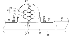
- FIG. 1 is a cross-sectional view illustrating a wire harness 10 according to an embodiment.
- the wire harness 10 is used as a wiring member that is mounted on a vehicle and electrically connects various devices.
- the wire harness 10 includes an electric wire 20 and a sheet material 30.
- one electric wire 20 is arranged for one sheet material 30, but of course, a plurality of electric wires 20 may be arranged for one sheet material 30. .
- the electric wire 20 is connected to various devices mounted on the vehicle via, for example, terminals or connectors connected to the ends.
- the electric wire 20 includes a core wire 22 and an insulating coating 26 that covers the core wire 22.
- the core wire 22 is composed of one or a plurality of wires (seven in the example shown in FIG. 1). Each strand 23 is a member formed in a linear shape by a conductive material such as copper, copper alloy, aluminum, aluminum alloy. When the core wire 22 includes a plurality of strands 23, the strand 22 is preferably a twisted strand in which the strands 23 are twisted.
- the insulating coating 26 is formed by extruding an insulating resin material such as polyvinyl chloride (PVC) or polyethylene (PE) around the core wire 22, or applying a resin paint such as enamel around the core wire 22. It is formed by.
- the insulating coating 26 includes a thermoplastic resin.
- the insulating coating 26 will be described as being formed of a resin material containing PVC.
- the insulating coating 26 is made of a material in which a plasticizer is added based on PVC.
- a plasticizer is an additive for softening a synthetic resin product.
- a product having a high plasticizer ratio relative to the synthetic resin is generally softer than a product having a low plasticizer ratio.
- the kind of the plasticizer is not particularly limited, and plasticizers such as phthalic acid ester, trimellitic acid ester, pyromellitic acid ester, fatty acid ester, and fatty acid polyester can be used.
- a plasticizer may be used individually by 1 type and multiple types may be used together.
- various additives such as a stabilizer may be added to the PVC constituting the insulating coating 26.
- the electric wire 20 is fixed to the sheet material 30 by welding the insulating coating 26 to the sheet material 30 (in this case, ultrasonic welding) in at least a part of the portion disposed on the sheet material 30.
- the arrangement path of the electric wire 20 with respect to the sheet material 30 is not particularly limited.
- the electric wire 20 may extend linearly with respect to the sheet material 30 or may be bent and extended.
- all the some electric wires 20 may extend in the same direction, and one part may extend in a different direction.
- seat material 30 may be formed.
- region of the electric wire 20 disposed on the sheet material 30 along the longitudinal direction is welded is not particularly limited.
- the insulating coating 26 and the sheet material 30 may be welded in series along the longitudinal direction of the electric wire 20, or partial welding (spot welding) is performed at a plurality of locations along the longitudinal direction of the electric wire 20. It may be done.
- spot welding spot welding
- seat material 30 among the electric wires 20 may be welded, and there may be a section which is not partly welded.
- the pitch between spot welds may be constant or may not be constant.
- the outer peripheral surface of the portion of the insulating coating 26 welded to the sheet material 30 is formed in a shape that is partially deformed from the circumferential surface shape.
- a so-called round electric wire having a uniform circumferential surface shape is adopted as the electric wire 20 and a part of the insulating coating 26 in the round electric wire is deformed to form the electric wire 20.
- the sheet material 30 includes a resin-made electric wire fixing layer 32.
- the sheet material 30 will be described as having a single-layer structure including only the electric wire fixing layer 32.
- the electric wire 20 is disposed on the main surface 33 of the resin electric wire fixing layer 32.
- a portion of the main surface 33 that comes into contact with the electric wire 20 is welded to the insulating coating 26 of the electric wire 20 to form the electric wire fixing portion 34.
- a portion of the wire fixing layer 32 that is not the wire fixing portion 34 that is, a portion where the electric wire 20 is not disposed on the main surface 33 is referred to as a wire non-arranged portion 36.
- the portion including the wire fixing portion 34 is formed to be the same as or harder than the insulating coating 26.
- Such hardness can use, for example, Rockwell hardness as an index.
- the material constituting the portion including the wire fixing portion 34 in the sheet material 30 is not particularly limited as long as it can be welded to the insulating coating 26.
- the portion of the sheet material 30 that includes the wire fixing portion 34 preferably includes the same resin as the insulating coating 26. Thereby, the joining strength of the electric wire fixing
- the insulation coating 26 includes PVC, the description will be made assuming that the portion of the sheet material 30 including the wire fixing portion 34 is also formed of a material including PVC.
- a portion of the sheet material 30 including the wire fixing portion 34 is formed of a material in which a plasticizer is added based on PVC.
- the kind of the plasticizer is not particularly limited, and for example, plasticizers such as the above-mentioned phthalic acid ester, trimellitic acid ester, pyromellitic acid ester, fatty acid ester, and fatty acid polyester can be used.
- a plasticizer may be used individually by 1 type and multiple types may be used together.
- the plasticizer added to PVC which comprises the part containing the electric wire fixing part 34 is demonstrated as what is the same as the plasticizer added to PVC used as the material of the insulation coating 26.
- the portion including the wire fixing portion 34 is present. It is the same as or harder than the insulating coating 26.
- the plasticizer added to the PVC constituting the portion including the wire fixing portion 34 may be different from the plasticizer added to the PVC constituting the insulating coating 26.
- various additives such as a stabilizer may be added to the PVC constituting the portion including the wire fixing portion 34.
- the sheet material 30 and the insulating coating 26 are welded in a state where the insulating coating 26 is deformed so as to follow the main surface 33 of the sheet material 30.
- the boundary surface for welding with the electric wire fixing portion 34 is formed in a shape closer to the shape of the main surface 33 in the electric wire non-arranged portion 36 than the circumferential surface shape of the insulating coating 26.
- the above-described deformation in the insulating coating 26 will be described as occurring at the time of ultrasonic welding. That is, by ultrasonic welding of the round wire and the sheet material 30, the portion of the insulating coating 26 that is ultrasonically welded to the sheet material 30 extends along the main surface 33 of the sheet material 30 from the original circumferential surface shape. It is deformed into a shape (here, a shape close to a flat surface). As described above, the insulating coating 26 is deformed at the time of ultrasonic welding because the sheet material 30 is the same as or harder than the insulating coating 26 as described above, and thus the deformation amount of the insulating coating 26 at the time of ultrasonic welding. Is considered to be larger than the deformation amount of the sheet material 30.
- FIG. 2 is a diagram for explaining the thickness dimension of each part in the wire harness 10. In FIG. 2, cross-sectional hatching is omitted.
- Dimension A in FIG. 2 is the thickness dimension of the first covering portion 27a located on the wire fixing portion 34 side with respect to the core wire 22 in the insulating coating 26.
- the dimension A is a thickness dimension in a direction along the normal direction of the main surface 33 of the sheet material 30 through the center of the core wire 22, for example.
- the position of the dimension A is a portion where the electric wire 20 and the sheet material 30 first contact each other at the time of ultrasonic welding, for example.
- Dimension B in FIG. 2 is the thickness dimension of the second covering portion 27b located on the opposite side of the insulating coating 26 from the first covering portion 27a with respect to the core wire 22.
- the dimension B is a thickness dimension in the same direction as the dimension A, for example.
- the dimension C is a thickness dimension in the same direction as the dimension A, for example.
- Dimension D in FIG. 2 is a thickness dimension at a position away from the electric wire 20 in the sheet material 30.
- the dimension D is considered to be the dimension of the thickest part in the part including the electric wire non-arranged part 36.
- the dimension D is considered to be the same as the thickness dimension of the sheet material 30 before welding.
- the thickness dimension A of the first covering portion 27 a on the wire fixing portion 34 side with respect to the core wire 22 in the insulating coating 26 is larger than the thickness dimension B of the second covering portion 27 b on the opposite side. It is formed in small size. Thereby, the thickness dimension as the wire harness 10 is small.
- the sum of the thickness dimension C of the sheet material 30 where the first covering portion 27a is welded and the thickness dimension A of the first covering portion 27a is the thickness of the second covering portion 27b. It is formed with dimension B or more. Thereby, the insulation performance by the side of the 1st covering part 27a can be improved.
- the dimension C is formed to be smaller than the dimension D, but it may be formed to be the same as or larger than the dimension D.
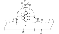
- FIG. 3 is a diagram illustrating the width dimension of each part in the wire harness 10.
- cross-sectional hatching is omitted.
- the width dimension here is a dimension in the direction along the direction in which the main surface 33 of the sheet material 30 spreads, and is the dimension in the direction along the direction (orthogonal direction) intersecting the pressing direction during welding. It is.
- the dimension E is a dimension from one end portion to the other end portion of the boundary surface of the welded portion between the insulating coating 26 and the sheet material 30.
- the dimension F in FIG. 3 is a width dimension in a portion passing through the center of the core wire 22 in the electric wire 20.
- the dimension F corresponds to the diameter of the electric wire 20 before welding, for example.
- the width dimension E at the boundary surface of the welded portion between the insulating coating 26 and the sheet material 30 is larger than the width dimension F in the portion of the electric wire 20 passing through the center of the core wire 22. Is formed. As a result, the area related to welding is increased, so that the bonding strength between the insulating coating 26 and the sheet material 30 can be improved.
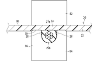
- FIG.4 and FIG.5 is a figure explaining a mode that the wire harness 10 which concerns on embodiment is manufactured.
- description of the electric wire 20B etc. which are shown in FIG.4 and FIG.5 has shown that it is the state before welding. That is, in the following, when it is necessary to distinguish the wire and sheet material before welding and their respective parts from those after welding, those indicating the state before welding may be described with reference B.
- the wire harness 10 is manufactured by ultrasonically welding the electric wire 20B and the sheet material 30B with the ultrasonic welding machine 80.
- the electric wire 20B is a round electric wire.
- the sheet material 30B is a member composed of one layer, and the electric wire arrangement portion 34B where the electric wires 20B are arranged is a flat surface.
- the ultrasonic welder 80 includes a horn 82 and an anvil 84.
- the horn 82 is a member that applies ultrasonic vibration to a workpiece that comes into contact. It is also conceivable that the surface of the horn 82 that comes into contact with the workpiece has a concavo-convex shape for the purpose of knurling, that is, for preventing slipping.
- the anvil 84 is a member that supports the workpiece from the opposite side with respect to the horn 82. Therefore, in a state where the pair of parts to be welded in the workpiece are sandwiched between the horn 82 and the anvil 84, ultrasonic vibration is applied and the workpiece is welded.
- the electric wire 20B is disposed on the electric wire arrangement portion 34B formed on the resin sheet material 30B that is the same as or harder than the insulating coating 26B. And the electric wire arrangement part 34B are clamped by a clamping member.
- the electric wire 20B before welding is supported by the anvil 84 while being arranged at a predetermined position (electric wire arrangement part 34B) on the main surface 33 of the sheet material 30B before welding.
- the horn 82 is approached toward the anvil 84, the electric wire 20B and the sheet material 30B are sandwiched by the horn 82 and the anvil 84, and the insulating coating 26B and the electric wire arrangement portion 34B are brought into contact with each other.
- the horn 82 is arranged to hold the sheet material 30B side and the anvil 84 is arranged to hold the electric wire 20B side, but the horn is arranged to hold the electric wire 20B side and the anvil is pressed to the sheet material 30B side. The case where it is done is also considered.
- a holding groove 85 for holding the electric wire 20B is formed on the surface of the anvil 84 facing the horn 82 side.
- the bottom of the holding groove 85 may be flat or curved. In the example shown in FIG. 4, the bottom of the holding groove 85 is formed in a curved surface shape.
- the depth of the holding groove 85 is set to be approximately the same as the diameter of the electric wire 20B (slightly smaller than the diameter of the electric wire 20B in the example shown in FIG. 4).
- the distal end portion of 86 functions as a presser portion 89 that holds the undisposed portion of the electric wire 20 ⁇ / b> B together with the horn 82 in the sheet material 30 ⁇ / b> B with the horn 82.
- the width of the opening side of the holding groove 85 is set to be constant with respect to the curved surface.
- the inner surface of the wall 86 extending from the bottom of the holding groove 85 to the tip of the presser 89 is a vertical surface 87.
- the wire harness 10 is preferably thin.
- the sheet material 30B is preferably thin.
- the thickness dimension of the sheet material 30B before welding is set smaller than the diameter of the electric wire 20B.
- the thickness dimension of the sheet material 30B before welding may be the same as the diameter of the electric wire 20B, or may be set larger than the diameter of the electric wire 20B.
- the thickness dimension of the sheet material 30B before welding is set smaller than the radius of the electric wire 20B.
- the thickness dimension of the sheet material 30B before welding may be the same as the radius of the electric wire 20B, or may be set larger than the radius of the electric wire 20B.
- the thickness dimension of the sheet material 30B before welding is set to be larger than the thickness dimension of the insulating coating 26B (here, the average thickness dimension in view of the presence of the plurality of strands 23).
- the thickness dimension of the sheet material 30B before welding may be the same as the thickness dimension of the insulating coating 26B, or may be set smaller than the thickness dimension of the insulating coating 26B.
- the insulation coating 26 and the electric wire arrangement part 34B are ultrasonically welded in a state where the electric wire 20B and the electric wire arrangement part 34B are held by the holding member.
- ultrasonic vibration is applied by the horn 82 in a state where the portion where the insulating coating 26B and the sheet material 30B are in contact with each other is sandwiched by the horn 82 and the anvil 84.
- the horn 82 presses the sheet material 30B side
- ultrasonic vibration is applied from the sheet material 30B side. Friction heat resulting from ultrasonic vibration is generated at the portion where the insulating coating 26B and the sheet material 30B are in contact with each other, and at least one of them is melted to join them.
- both the insulation coating 26B and the sheet material 30B are formed of a PVC-based material, both are melted and joined.
- the electric wire arrangement part 34B is in the same or harder state than the insulating coating 26B.
- both the insulation coating 26B and the electric wire arrangement portion 34B are formed of a material containing PVC and a plasticizer.
- the ratio of the plasticizer to the PVC constituting the portion including the electric wire arranging portion 34B is equal to or higher than the ratio of the plasticizer to the PVC constituting the insulating coating 26. Low. This state is continued even at the time when ultrasonic welding is performed, and at the time when ultrasonic welding is performed, the portion including the electric wire arranging portion 34B is the same as or more than the insulating coating 26B. Is in a hard state.
- the portion including the electric wire arrangement portion 34B is in the same or harder state as the insulating coating 26B, so that the electric wire arrangement portion 34B and the insulating coating 26B are in contact with each other.
- the force applied by the horn 82 and the anvil 84 is likely to act as a force for deforming the insulating coating 26B.
- the boundary between the electric wire fixing portion 34 and the insulating coating 26 formed by welding the electric wire arranging portion 34B is less than the circumferential surface shape that is the original outer peripheral surface of the insulating coating 26 before the electric wire arranging portion. It is formed in a shape close to the shape of the main surface 33 of 34B.
- the circumferential surface shape which is the original outer peripheral surface of the insulation coating 26 can be confirmed in the portion where there is a portion that is not welded along the longitudinal direction of the electric wire 20, for example. Further, here, even in the portion welded along the longitudinal direction of the electric wire 20, the surface opposite to the surface to be welded is not easily deformed when welded. The shape can also be confirmed.
- the outer surface of the deformed portion 28 of the insulating coating 26 is shaped along the inner surface of the holding groove 85 of the anvil 84 by damming the insulating coating 26 softened during welding on the inner surface of the holding groove 85 of the anvil 84. Is done.
- the inner surface of the holding groove 85 of the anvil 84 is the vertical surface 87
- the outer surface of the deformed portion 28 is a vertical surface 28 a corresponding to the vertical surface 87.
- a portion far from the sheet material 30 may have an interface 29 with the original insulating coating 26.
- the interface 29 may be generated when the original insulating coating 26 portion does not melt due to a small energy applied to the deformed portion 28 during ultrasonic welding.
- the energy applied to the deformed portion 28 during ultrasonic welding is large, the original insulating coating 26 portion may melt, and the interface 29 may not be formed.
- the concave portion 39 may be formed in a portion pressed by the presser portion 89 on the main surface 33 of the sheet material 30 after welding.
- the recess 39 may not be formed.
- the wire harness 10 can be thinned by the amount that the thickness dimension A of the first covering portion 27a is smaller than the thickness dimension B of the second covering portion 27b. At this time, the insulation performance of the thinned first covering portion 27 a can be supplemented by the sheet material 30.
- the width dimension E at the boundary surface of the welded portion between the insulating coating 26 and the sheet material 30 is formed larger than the width dimension F at the portion passing through the core wire 22 of the electric wire 20, the bonding strength for welding is increased. Can be increased.
- portion including the wire fixing portion 34 is formed to be the same as or harder than the insulating coating 26, it is easy to make the thickness dimension of the first covering portion 27a smaller than the thickness dimension of the second covering portion 27b. .
- the wire arrangement portion 34B and the wire fixing portion 34 are harder than the insulation coating 26 by adjusting the ratio of the plasticizer. Can be formed.
- the softness of the sheet material 30 and the insulating coating 26 is adjusted using a plasticizer.
- the plasticizer may move to a contact member over time. For this reason, after ultrasonic welding, the plasticizer may be transferred between the wire fixing portion 34 and the insulating coating 26.
- the plasticizer of the wire fixing portion 34 and the plasticizer of the insulating coating 26 are in an equilibrium state, and the electric wire fixing portion 34 and the insulating coating 26 are in contact with each other. The same hardness can be considered.
- the insulating coating 26 may be harder than the wire fixing portion 34 by processing after ultrasonic welding (for example, only the wire fixing portion 34 of the electric wire 20 and the wire fixing portion 34 is heated and pressed). possible. Even in these cases, it is considered that the boundary surface between the wire fixing portion 34 and the insulating coating 26 remains in the shape along the main surface 33.
- the sheet material 30 is the same as or harder than the insulating coating 26 in the temperature heated by the frictional heat at the time of ultrasonic welding and under pressure, the sheet material of the insulating coating 26 when the welding is proceeded as it is.
- the portion on the 30 side is the same as or easier to deform than the sheet material 30. For this reason, even if it uses the electric wire 20 with the thickness of the insulation coating 26 uniform, the part by the side of the sheet
- FIG. 6 is a cross-sectional view showing a wire harness 110 according to a modification.
- the sheet material 30 has been described as one layer, but this is not an essential configuration. A case where there are two or more layers, such as the sheet material 130 in the wire harness 110 according to the modification, is also conceivable.
- the sheet material 130 includes a first layer 32 as the wire fixing layer 32 and a second layer 40 laminated on the first layer 32.
- the first layer 32 is uniformly formed of the same material as that constituting the portion including the wire fixing portion 34. Therefore, the first layer 32 is formed of a material to which the same plasticizer as the plasticizer added to the insulating coating 26 is added based on PVC.
- the ratio of the plasticizer to the PVC constituting the first layer 32 is equal to or higher than the ratio of the plasticizer to the PVC constituting the insulating coating 26, so that the first layer 32 is equal to or higher than the insulating coating 26. Is also hard.
- the second layer 40 has physical properties different from those of the first layer 32. More specifically, the first layer 32 is a portion having physical properties that are more suitable for welding with the insulating coating 26 than the second layer 40, and the second layer 40 has physical properties that are necessary depending on the use of the sheet material 30. It is a part that has.
- the second layer 40 may be formed to be harder than the first layer 32 for the purpose of improving shape retention.
- the handleability of the wire harness 10 at the time of assembling the wire harness 10 to a vehicle can be improved.
- the second layer 40 is formed to be harder than the first layer 32 for the purpose of improving wear resistance.
- the second layer 40 is formed to be harder than the first layer 32 by the same resin-based material as the first layer 32.
- the first layer 32 is based on PVC
- the second layer 40 is based on PVC.
- the ratio of the plasticizer to the PVC constituting the second layer 40 lower than the ratio of the plasticizer to the PVC constituting the first layer 32, the second layer 40 is made more than the first layer 32. Can also be hardened.
- the second layer 40 is formed to be harder than the first layer 32 by a material based on a resin different from the first layer 32.
- the first layer 32 is based on PVC
- the second layer 40 is formed of a material based on a resin other than PVC, for example, PE, polypropylene (PP), polyethylene terephthalate (PET), or the like. Can be considered.
- the method for forming the sheet material 30 having the first layer 32 and the second layer 40 is not particularly limited.
- the sheet material 30 may be formed by a coextrusion method that realizes a laminated structure in a single extrusion process, It is conceivable that the first layer 32 and the second layer 40 may be formed by a laminating method in which the first layer 32 and the second layer 40 are once separately formed into a sheet shape and then bonded together.
- the sheet material 130 is configured to have a shielding property or enhance a heat dissipation property by employing a metal foil such as an aluminum foil as the second layer 40.
- the sheet material 130 is configured to enhance the soundproofing function by employing a nonwoven fabric or a foamed resin sheet that is softer than the first layer 32 as the second layer 40.
- the sheet material has a three-layer structure or more. That is, it is conceivable that the third layer and the fourth layer are stacked in this order on the opposite side of the second layer 40 from the first layer 32.
- the insulating coating 26 is deformed from the circumferential surface shape to a shape close to the main surface 33 of the sheet material 30 during ultrasonic welding, this is not an essential configuration.
- the insulating coating 26 may be deformed from a circumferential surface shape to a shape close to the main surface 33 of the sheet material 30 in advance.
- a part of the circumferential surface shape may be extruded into a flat shape.
- the sheet material 30 may be formed softer than the insulating coating 26.
- the sum of the thickness dimension C of the portion of the sheet material 30 where the first covering portion 27a has been welded and the thickness dimension A of the first covering portion 27a is greater than or equal to the thickness dimension B of the second covering portion 27b.
- this is not an essential configuration.
- the insulating performance of the sheet material 30 is preferably higher than the insulating performance of the insulating coating 26. That is, the sum of the thickness dimension C and the thickness dimension A may be smaller than the thickness dimension B as long as it has an insulation performance equal to or higher than that of the second covering portion 27b.
- width dimension E in the boundary surface of the welding part of the insulating coating 26 and the sheet material 30 has been described so far as being formed larger than the width dimension F in the part passing through the core wire 22 of the electric wire 20. This is not an essential configuration. It can also be understood that the width dimension E at the boundary surface of the welded portion between the insulating coating 26 and the sheet material 30 is equal to or less than the width dimension F at the portion passing through the core wire 22 of the electric wire 20.
- the welding portion can be reduced by reducing the pressure during ultrasonic welding or by reducing the vibration energy to be applied.
- the electric wire 20 has been described as a round electric wire so far, but this is not an essential configuration.
- the electric wire 20 may be an electric wire other than a round electric wire such as a square electric wire.
- the insulating coating 26 and the wire fixing layer 32 are formed of a PVC-based material, this is not an essential configuration.
- the insulating coating 26 and the wire fixing layer 32 may be formed of a material based on PE or PP. In this case, the density of the PE or PP used as the base of the insulating coating 26 is reduced to the same or lower density than the PE or PP used as the base of the electric wire fixing layer 32, or isobutylene or the like By making it react, the electric wire fixing layer 32 can be made the same as or harder than the insulating coating 26.
- the outer surface of the deformed portion 28 has a shape along the inner surface of the anvil 84
- the outer surface of the deformable portion 28 may not have a shape along the inner surface of the anvil 84.
- the deformed portion 28 is likely to spread along the main surface 33 of the sheet material 30, and as a result, the dimension E may be larger than that shown in FIG. 3.
Landscapes
- Engineering & Computer Science (AREA)
- Manufacturing & Machinery (AREA)
- Physics & Mathematics (AREA)
- Spectroscopy & Molecular Physics (AREA)
- Details Of Indoor Wiring (AREA)
- Insulated Conductors (AREA)
Priority Applications (3)
| Application Number | Priority Date | Filing Date | Title |
|---|---|---|---|
| US17/043,105 US11501898B2 (en) | 2018-03-30 | 2018-08-22 | Wire harness and method of manufacturing wire harness |
| CN201880091664.XA CN111902886B (zh) | 2018-03-30 | 2018-08-22 | 线束和线束的制造方法 |
| DE112018007407.2T DE112018007407T5 (de) | 2018-03-30 | 2018-08-22 | Kabelstrang und verfahren zur herstellung eines kabelstrangs |
Applications Claiming Priority (2)
| Application Number | Priority Date | Filing Date | Title |
|---|---|---|---|
| JP2018067192A JP6665882B2 (ja) | 2018-03-30 | 2018-03-30 | ワイヤーハーネス及びワイヤーハーネスの製造方法 |
| JP2018-067192 | 2018-03-30 |
Publications (1)
| Publication Number | Publication Date |
|---|---|
| WO2019187196A1 true WO2019187196A1 (ja) | 2019-10-03 |
Family
ID=68058061
Family Applications (1)
| Application Number | Title | Priority Date | Filing Date |
|---|---|---|---|
| PCT/JP2018/030915 Ceased WO2019187196A1 (ja) | 2018-03-30 | 2018-08-22 | ワイヤーハーネス及びワイヤーハーネスの製造方法 |
Country Status (5)
| Country | Link |
|---|---|
| US (1) | US11501898B2 (enExample) |
| JP (1) | JP6665882B2 (enExample) |
| CN (1) | CN111902886B (enExample) |
| DE (1) | DE112018007407T5 (enExample) |
| WO (1) | WO2019187196A1 (enExample) |
Cited By (1)
| Publication number | Priority date | Publication date | Assignee | Title |
|---|---|---|---|---|
| US20210118590A1 (en) * | 2018-03-28 | 2021-04-22 | Autonetworks Technologies, Ltd. | Wire harness and method of manufacturing wire harness |
Families Citing this family (2)
| Publication number | Priority date | Publication date | Assignee | Title |
|---|---|---|---|---|
| US10639737B1 (en) * | 2018-10-19 | 2020-05-05 | Aptiv Technologies Limited | Welding system and method |
| WO2022158391A1 (ja) | 2021-01-20 | 2022-07-28 | 古河電気工業株式会社 | 接合構造体およびその製造方法、ならびに電線用外装体 |
Citations (3)
| Publication number | Priority date | Publication date | Assignee | Title |
|---|---|---|---|---|
| JP2002050236A (ja) * | 2000-08-07 | 2002-02-15 | Yazaki Corp | 電線付き導体薄膜シートと電線付き導体薄膜シートの製造方法 |
| JP2003257513A (ja) * | 2002-02-27 | 2003-09-12 | Yazaki Corp | 被覆電線の接続方法および接続構造 |
| JP2015090783A (ja) * | 2013-11-05 | 2015-05-11 | 住友電装株式会社 | ワイヤハーネス |
Family Cites Families (18)
| Publication number | Priority date | Publication date | Assignee | Title |
|---|---|---|---|---|
| US3857995A (en) * | 1972-11-24 | 1974-12-31 | Amp Inc | Electrical connector |
| JPS5141910B2 (enExample) * | 1972-12-12 | 1976-11-12 | ||
| JPS5054597A (enExample) | 1973-09-06 | 1975-05-14 | ||
| JPS5054597U (enExample) * | 1973-09-14 | 1975-05-24 | ||
| JPH0636330B2 (ja) * | 1985-06-17 | 1994-05-11 | 矢崎総業株式会社 | ワイヤ−ハ−ネスの製造方法 |
| US6578263B2 (en) * | 1996-06-04 | 2003-06-17 | Yazaki Corporation | Method of manufacturing a wire harness |
| AU4173197A (en) | 1996-10-18 | 1998-05-15 | W.L. Gore & Associates, Inc. | Microminiature planar signal transmission cable |
| JP4504529B2 (ja) * | 2000-08-07 | 2010-07-14 | 矢崎総業株式会社 | 電線同士の接続方法 |
| JP2002080819A (ja) * | 2000-09-06 | 2002-03-22 | Tentac Co Ltd | 熱接着フィルム |
| JP2002216871A (ja) | 2001-01-19 | 2002-08-02 | Yazaki Corp | 電線付き導体薄膜シートと該電線付き導体薄膜シートの製造方法 |
| JP4914539B2 (ja) | 2001-05-18 | 2012-04-11 | 矢崎総業株式会社 | シールドハーネスの組立方法 |
| US8653172B2 (en) * | 2010-03-17 | 2014-02-18 | Exxonmobil Chemical Patents Inc. | Plasticiser blends and compositions and articles made therefrom |
| JP5441826B2 (ja) * | 2010-06-14 | 2014-03-12 | 株式会社オートネットワーク技術研究所 | 防食剤、端子付き被覆電線およびワイヤーハーネス |
| JP5900407B2 (ja) * | 2012-11-08 | 2016-04-06 | 住友電装株式会社 | ワイヤハーネス |
| JP5904106B2 (ja) * | 2012-11-30 | 2016-04-13 | 日立金属株式会社 | ケーブルコネクタおよびケーブルアッセンブリならびにケーブルアッセンブリの製造方法 |
| WO2014112157A1 (ja) * | 2013-01-16 | 2014-07-24 | 株式会社オートネットワーク技術研究所 | 硬化材料、ワイヤーハーネス及びその製造方法 |
| DE112014001580T5 (de) * | 2013-03-22 | 2015-12-03 | Autonetworks Technologies, Ltd. | Ummantelter elektrischer Draht mit einer Klemme |
| JP5979113B2 (ja) | 2013-10-03 | 2016-08-24 | 住友電装株式会社 | ワイヤハーネス |
-
2018
- 2018-03-30 JP JP2018067192A patent/JP6665882B2/ja active Active
- 2018-08-22 US US17/043,105 patent/US11501898B2/en active Active
- 2018-08-22 WO PCT/JP2018/030915 patent/WO2019187196A1/ja not_active Ceased
- 2018-08-22 CN CN201880091664.XA patent/CN111902886B/zh active Active
- 2018-08-22 DE DE112018007407.2T patent/DE112018007407T5/de active Pending
Patent Citations (3)
| Publication number | Priority date | Publication date | Assignee | Title |
|---|---|---|---|---|
| JP2002050236A (ja) * | 2000-08-07 | 2002-02-15 | Yazaki Corp | 電線付き導体薄膜シートと電線付き導体薄膜シートの製造方法 |
| JP2003257513A (ja) * | 2002-02-27 | 2003-09-12 | Yazaki Corp | 被覆電線の接続方法および接続構造 |
| JP2015090783A (ja) * | 2013-11-05 | 2015-05-11 | 住友電装株式会社 | ワイヤハーネス |
Cited By (2)
| Publication number | Priority date | Publication date | Assignee | Title |
|---|---|---|---|---|
| US20210118590A1 (en) * | 2018-03-28 | 2021-04-22 | Autonetworks Technologies, Ltd. | Wire harness and method of manufacturing wire harness |
| US11521764B2 (en) * | 2018-03-28 | 2022-12-06 | Autonetworks Technologies, Ltd. | Wire harness and method of manufacturing wire harness |
Also Published As
| Publication number | Publication date |
|---|---|
| CN111902886A (zh) | 2020-11-06 |
| CN111902886B (zh) | 2022-05-03 |
| US11501898B2 (en) | 2022-11-15 |
| JP6665882B2 (ja) | 2020-03-13 |
| US20210027916A1 (en) | 2021-01-28 |
| JP2019179630A (ja) | 2019-10-17 |
| DE112018007407T5 (de) | 2020-12-10 |
Similar Documents
| Publication | Publication Date | Title |
|---|---|---|
| JP6798471B2 (ja) | ワイヤーハーネスおよびワイヤーハーネスの製造方法 | |
| JP6365704B1 (ja) | ワイヤーハーネス | |
| JP2009093934A (ja) | シールド電線及びシールド電線の製造方法 | |
| JP6665882B2 (ja) | ワイヤーハーネス及びワイヤーハーネスの製造方法 | |
| WO2019189177A1 (ja) | ワイヤーハーネス | |
| WO2018235788A1 (ja) | ワイヤーハーネスおよびワイヤーハーネスの製造方法 | |
| JP7147839B2 (ja) | ワイヤーハーネスおよびワイヤーハーネスの製造方法 | |
| JP7192628B2 (ja) | 配線部材 | |
| WO2016158455A1 (ja) | 外装ワイヤーハーネス | |
| JP6923023B2 (ja) | ワイヤーハーネス及びワイヤーハーネスの製造方法 | |
| JP2019179630A5 (enExample) | ||
| JP6665881B2 (ja) | ワイヤーハーネス及びワイヤーハーネスの製造方法 | |
| JP2018156961A (ja) | ワイヤーハーネス | |
| JP2023102826A (ja) | 配線部材及び配線部材の製造方法 | |
| JP7056621B2 (ja) | 配線部材 | |
| WO2020039914A1 (ja) | 配線部材 | |
| JP4591166B2 (ja) | フラットケーブル及びその製造方法 | |
| WO2025263401A1 (ja) | 配線部材 | |
| JP2020092097A5 (enExample) | ||
| JP2025104449A (ja) | 配線部材及び配線部材の製造方法 | |
| JP2024114161A (ja) | 超音波接合方法 | |
| JP2005312143A (ja) | フラットケーブルの固定構造 | |
| JP2015076242A (ja) | 端子付電線 |
Legal Events
| Date | Code | Title | Description |
|---|---|---|---|
| 121 | Ep: the epo has been informed by wipo that ep was designated in this application |
Ref document number: 18911902 Country of ref document: EP Kind code of ref document: A1 |
|
| 122 | Ep: pct application non-entry in european phase |
Ref document number: 18911902 Country of ref document: EP Kind code of ref document: A1 |