WO2019187196A1 - Wire harness and wire harness production method - Google Patents
Wire harness and wire harness production method Download PDFInfo
- Publication number
- WO2019187196A1 WO2019187196A1 PCT/JP2018/030915 JP2018030915W WO2019187196A1 WO 2019187196 A1 WO2019187196 A1 WO 2019187196A1 JP 2018030915 W JP2018030915 W JP 2018030915W WO 2019187196 A1 WO2019187196 A1 WO 2019187196A1
- Authority
- WO
- WIPO (PCT)
- Prior art keywords
- electric wire
- wire
- insulating coating
- sheet material
- wire harness
- Prior art date
Links
Images


Classifications
-
- H—ELECTRICITY
- H01—ELECTRIC ELEMENTS
- H01B—CABLES; CONDUCTORS; INSULATORS; SELECTION OF MATERIALS FOR THEIR CONDUCTIVE, INSULATING OR DIELECTRIC PROPERTIES
- H01B7/00—Insulated conductors or cables characterised by their form
- H01B7/40—Insulated conductors or cables characterised by their form with arrangements for facilitating mounting or securing
-
- H—ELECTRICITY
- H01—ELECTRIC ELEMENTS
- H01B—CABLES; CONDUCTORS; INSULATORS; SELECTION OF MATERIALS FOR THEIR CONDUCTIVE, INSULATING OR DIELECTRIC PROPERTIES
- H01B13/00—Apparatus or processes specially adapted for manufacturing conductors or cables
- H01B13/012—Apparatus or processes specially adapted for manufacturing conductors or cables for manufacturing wire harnesses
- H01B13/01209—Details
-
- H—ELECTRICITY
- H01—ELECTRIC ELEMENTS
- H01B—CABLES; CONDUCTORS; INSULATORS; SELECTION OF MATERIALS FOR THEIR CONDUCTIVE, INSULATING OR DIELECTRIC PROPERTIES
- H01B3/00—Insulators or insulating bodies characterised by the insulating materials; Selection of materials for their insulating or dielectric properties
- H01B3/18—Insulators or insulating bodies characterised by the insulating materials; Selection of materials for their insulating or dielectric properties mainly consisting of organic substances
- H01B3/30—Insulators or insulating bodies characterised by the insulating materials; Selection of materials for their insulating or dielectric properties mainly consisting of organic substances plastics; resins; waxes
- H01B3/44—Insulators or insulating bodies characterised by the insulating materials; Selection of materials for their insulating or dielectric properties mainly consisting of organic substances plastics; resins; waxes vinyl resins; acrylic resins
- H01B3/448—Insulators or insulating bodies characterised by the insulating materials; Selection of materials for their insulating or dielectric properties mainly consisting of organic substances plastics; resins; waxes vinyl resins; acrylic resins from other vinyl compounds
-
- B—PERFORMING OPERATIONS; TRANSPORTING
- B60—VEHICLES IN GENERAL
- B60R—VEHICLES, VEHICLE FITTINGS, OR VEHICLE PARTS, NOT OTHERWISE PROVIDED FOR
- B60R16/00—Electric or fluid circuits specially adapted for vehicles and not otherwise provided for; Arrangement of elements of electric or fluid circuits specially adapted for vehicles and not otherwise provided for
- B60R16/02—Electric or fluid circuits specially adapted for vehicles and not otherwise provided for; Arrangement of elements of electric or fluid circuits specially adapted for vehicles and not otherwise provided for electric constitutive elements
- B60R16/0207—Wire harnesses
-
- H—ELECTRICITY
- H01—ELECTRIC ELEMENTS
- H01B—CABLES; CONDUCTORS; INSULATORS; SELECTION OF MATERIALS FOR THEIR CONDUCTIVE, INSULATING OR DIELECTRIC PROPERTIES
- H01B7/00—Insulated conductors or cables characterised by their form
- H01B7/0045—Cable-harnesses
Definitions
- This invention relates to a technique for attaching an exterior member to an electric wire in a wire harness for a vehicle.
- Patent Document 1 when attaching a sheet-shaped exterior member to an electric wire, the exterior member is positioned with respect to the electric wire by applying tape winding around each end of the exterior member and the electric wire extending from the end.
- the technology is disclosed.
- the applicant of the present application has proposed a method of directly fixing the insulating coating of the electric wire and the sheet material by welding as a new fixing method of the electric wire and the sheet-shaped exterior member.
- the thickness of the wire harness may be, for example, the sum of the wire diameter before welding and the thickness of the sheet material.
- an object of the present invention is to provide a technique capable of reducing the thickness of a wire harness in which a wire insulation coating and a sheet material are directly welded and fixed.
- the wire harness according to the first aspect includes an electric wire including a core wire and an insulating coating covering the core wire, and the electric wire is disposed on a resin main surface, and the main surface A portion in contact with the electric wire is welded to the insulating coating of the electric wire and formed on the electric wire fixing portion, and the electric wire fixing portion side of the insulating coating on the side of the electric wire fixing portion is provided.
- the thickness dimension of one covering part is formed smaller than the thickness dimension of the second covering part on the opposite side.
- the wire harness which concerns on a 2nd aspect is a wire harness which concerns on a 1st aspect, Comprising: The thickness dimension of the part to which the said 1st coating part was welded among the said sheet materials, and the thickness dimension of the said 1st coating part, Is greater than the thickness dimension of the second covering portion.
- the wire harness which concerns on a 3rd aspect is a wire harness which concerns on the 1st or 2nd aspect, Comprising:
- seat material is the said core wire among the said electric wires. It is formed to be larger than the width dimension in the portion passing through the center.
- the wire harness according to the fourth aspect is a wire harness according to any one of the first to third aspects, and a portion including the wire fixing portion is formed to be the same as or harder than the insulating coating. .
- a wire harness according to a fifth aspect is the wire harness according to the fourth aspect, wherein the insulating coating and the electric wire fixing part are both formed of a material containing polyvinyl chloride and a plasticizer, and the electric wire fixing part is The portion including the wire fixing portion is the insulating coating because the ratio of the plasticizer to the polyvinyl chloride constituting the portion to be included is the same as or lower than the ratio of the plasticizer to the polyvinyl chloride constituting the insulating coating. It is the same or harder than that.
- the manufacturing method of the wire harness which concerns on a 6th aspect WHEREIN: While arrange
- a method for manufacturing a wire harness according to a seventh aspect is the method for manufacturing a wire harness according to the sixth aspect, wherein the insulating coating and the electric wire disposition portion are both formed of a material containing polyvinyl chloride and a plasticizer.
- the ratio of the plasticizer to the polyvinyl chloride constituting the portion including the electric wire arranging portion is the ratio of the plasticizer to the polyvinyl chloride constituting the insulating coating.
- the portion including the electric wire arrangement portion is the same as or harder than the insulating coating.
- the wire harness can be made thinner by the amount that the thickness dimension of the first covering portion is smaller than the thickness dimension of the second covering portion. At this time, the insulating performance of the thinned first covering portion can be supplemented with the sheet material.
- the insulation on the first covering portion side with respect to the core wire can be enhanced.
- the bonding strength required for welding can be increased.
- the fourth aspect it is easy to make the thickness dimension of the first covering portion smaller than the thickness dimension of the second covering portion.
- the wire fixing portion can be formed harder than the insulation coating.
- the sheet material is the same as or harder than the insulation coating at the temperature heated by the frictional heat at the time of ultrasonic welding and under pressure, when the welding is proceeded as it is, Among them, the part on the sheet material side is the same as the sheet material or more easily deformed. For this reason, even if it uses the electric wire with the uniform thickness of insulation coating, the part by the side of a sheet
- the wire arrangement portion can be formed to be the same as or harder than the insulation coating.
- FIG. 1 is a cross-sectional view illustrating a wire harness 10 according to an embodiment.
- the wire harness 10 is used as a wiring member that is mounted on a vehicle and electrically connects various devices.
- the wire harness 10 includes an electric wire 20 and a sheet material 30.
- one electric wire 20 is arranged for one sheet material 30, but of course, a plurality of electric wires 20 may be arranged for one sheet material 30. .
- the electric wire 20 is connected to various devices mounted on the vehicle via, for example, terminals or connectors connected to the ends.
- the electric wire 20 includes a core wire 22 and an insulating coating 26 that covers the core wire 22.
- the core wire 22 is composed of one or a plurality of wires (seven in the example shown in FIG. 1). Each strand 23 is a member formed in a linear shape by a conductive material such as copper, copper alloy, aluminum, aluminum alloy. When the core wire 22 includes a plurality of strands 23, the strand 22 is preferably a twisted strand in which the strands 23 are twisted.
- the insulating coating 26 is formed by extruding an insulating resin material such as polyvinyl chloride (PVC) or polyethylene (PE) around the core wire 22, or applying a resin paint such as enamel around the core wire 22. It is formed by.
- the insulating coating 26 includes a thermoplastic resin.
- the insulating coating 26 will be described as being formed of a resin material containing PVC.
- the insulating coating 26 is made of a material in which a plasticizer is added based on PVC.
- a plasticizer is an additive for softening a synthetic resin product.
- a product having a high plasticizer ratio relative to the synthetic resin is generally softer than a product having a low plasticizer ratio.
- the kind of the plasticizer is not particularly limited, and plasticizers such as phthalic acid ester, trimellitic acid ester, pyromellitic acid ester, fatty acid ester, and fatty acid polyester can be used.
- a plasticizer may be used individually by 1 type and multiple types may be used together.
- various additives such as a stabilizer may be added to the PVC constituting the insulating coating 26.
- the electric wire 20 is fixed to the sheet material 30 by welding the insulating coating 26 to the sheet material 30 (in this case, ultrasonic welding) in at least a part of the portion disposed on the sheet material 30.
- the arrangement path of the electric wire 20 with respect to the sheet material 30 is not particularly limited.
- the electric wire 20 may extend linearly with respect to the sheet material 30 or may be bent and extended.
- all the some electric wires 20 may extend in the same direction, and one part may extend in a different direction.
- seat material 30 may be formed.
- region of the electric wire 20 disposed on the sheet material 30 along the longitudinal direction is welded is not particularly limited.
- the insulating coating 26 and the sheet material 30 may be welded in series along the longitudinal direction of the electric wire 20, or partial welding (spot welding) is performed at a plurality of locations along the longitudinal direction of the electric wire 20. It may be done.
- spot welding spot welding
- seat material 30 among the electric wires 20 may be welded, and there may be a section which is not partly welded.
- the pitch between spot welds may be constant or may not be constant.
- the outer peripheral surface of the portion of the insulating coating 26 welded to the sheet material 30 is formed in a shape that is partially deformed from the circumferential surface shape.
- a so-called round electric wire having a uniform circumferential surface shape is adopted as the electric wire 20 and a part of the insulating coating 26 in the round electric wire is deformed to form the electric wire 20.
- the sheet material 30 includes a resin-made electric wire fixing layer 32.
- the sheet material 30 will be described as having a single-layer structure including only the electric wire fixing layer 32.
- the electric wire 20 is disposed on the main surface 33 of the resin electric wire fixing layer 32.
- a portion of the main surface 33 that comes into contact with the electric wire 20 is welded to the insulating coating 26 of the electric wire 20 to form the electric wire fixing portion 34.
- a portion of the wire fixing layer 32 that is not the wire fixing portion 34 that is, a portion where the electric wire 20 is not disposed on the main surface 33 is referred to as a wire non-arranged portion 36.
- the portion including the wire fixing portion 34 is formed to be the same as or harder than the insulating coating 26.
- Such hardness can use, for example, Rockwell hardness as an index.
- the material constituting the portion including the wire fixing portion 34 in the sheet material 30 is not particularly limited as long as it can be welded to the insulating coating 26.
- the portion of the sheet material 30 that includes the wire fixing portion 34 preferably includes the same resin as the insulating coating 26. Thereby, the joining strength of the electric wire fixing
- the insulation coating 26 includes PVC, the description will be made assuming that the portion of the sheet material 30 including the wire fixing portion 34 is also formed of a material including PVC.
- a portion of the sheet material 30 including the wire fixing portion 34 is formed of a material in which a plasticizer is added based on PVC.
- the kind of the plasticizer is not particularly limited, and for example, plasticizers such as the above-mentioned phthalic acid ester, trimellitic acid ester, pyromellitic acid ester, fatty acid ester, and fatty acid polyester can be used.
- a plasticizer may be used individually by 1 type and multiple types may be used together.
- the plasticizer added to PVC which comprises the part containing the electric wire fixing part 34 is demonstrated as what is the same as the plasticizer added to PVC used as the material of the insulation coating 26.
- the portion including the wire fixing portion 34 is present. It is the same as or harder than the insulating coating 26.
- the plasticizer added to the PVC constituting the portion including the wire fixing portion 34 may be different from the plasticizer added to the PVC constituting the insulating coating 26.
- various additives such as a stabilizer may be added to the PVC constituting the portion including the wire fixing portion 34.
- the sheet material 30 and the insulating coating 26 are welded in a state where the insulating coating 26 is deformed so as to follow the main surface 33 of the sheet material 30.
- the boundary surface for welding with the electric wire fixing portion 34 is formed in a shape closer to the shape of the main surface 33 in the electric wire non-arranged portion 36 than the circumferential surface shape of the insulating coating 26.
- the above-described deformation in the insulating coating 26 will be described as occurring at the time of ultrasonic welding. That is, by ultrasonic welding of the round wire and the sheet material 30, the portion of the insulating coating 26 that is ultrasonically welded to the sheet material 30 extends along the main surface 33 of the sheet material 30 from the original circumferential surface shape. It is deformed into a shape (here, a shape close to a flat surface). As described above, the insulating coating 26 is deformed at the time of ultrasonic welding because the sheet material 30 is the same as or harder than the insulating coating 26 as described above, and thus the deformation amount of the insulating coating 26 at the time of ultrasonic welding. Is considered to be larger than the deformation amount of the sheet material 30.
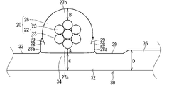
- FIG. 2 is a diagram for explaining the thickness dimension of each part in the wire harness 10. In FIG. 2, cross-sectional hatching is omitted.
- Dimension A in FIG. 2 is the thickness dimension of the first covering portion 27a located on the wire fixing portion 34 side with respect to the core wire 22 in the insulating coating 26.
- the dimension A is a thickness dimension in a direction along the normal direction of the main surface 33 of the sheet material 30 through the center of the core wire 22, for example.
- the position of the dimension A is a portion where the electric wire 20 and the sheet material 30 first contact each other at the time of ultrasonic welding, for example.
- Dimension B in FIG. 2 is the thickness dimension of the second covering portion 27b located on the opposite side of the insulating coating 26 from the first covering portion 27a with respect to the core wire 22.
- the dimension B is a thickness dimension in the same direction as the dimension A, for example.
- the dimension C is a thickness dimension in the same direction as the dimension A, for example.
- Dimension D in FIG. 2 is a thickness dimension at a position away from the electric wire 20 in the sheet material 30.
- the dimension D is considered to be the dimension of the thickest part in the part including the electric wire non-arranged part 36.
- the dimension D is considered to be the same as the thickness dimension of the sheet material 30 before welding.
- the thickness dimension A of the first covering portion 27 a on the wire fixing portion 34 side with respect to the core wire 22 in the insulating coating 26 is larger than the thickness dimension B of the second covering portion 27 b on the opposite side. It is formed in small size. Thereby, the thickness dimension as the wire harness 10 is small.
- the sum of the thickness dimension C of the sheet material 30 where the first covering portion 27a is welded and the thickness dimension A of the first covering portion 27a is the thickness of the second covering portion 27b. It is formed with dimension B or more. Thereby, the insulation performance by the side of the 1st covering part 27a can be improved.
- the dimension C is formed to be smaller than the dimension D, but it may be formed to be the same as or larger than the dimension D.
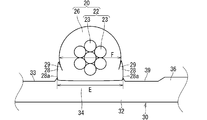
- FIG. 3 is a diagram illustrating the width dimension of each part in the wire harness 10.
- cross-sectional hatching is omitted.
- the width dimension here is a dimension in the direction along the direction in which the main surface 33 of the sheet material 30 spreads, and is the dimension in the direction along the direction (orthogonal direction) intersecting the pressing direction during welding. It is.
- the dimension E is a dimension from one end portion to the other end portion of the boundary surface of the welded portion between the insulating coating 26 and the sheet material 30.
- the dimension F in FIG. 3 is a width dimension in a portion passing through the center of the core wire 22 in the electric wire 20.
- the dimension F corresponds to the diameter of the electric wire 20 before welding, for example.
- the width dimension E at the boundary surface of the welded portion between the insulating coating 26 and the sheet material 30 is larger than the width dimension F in the portion of the electric wire 20 passing through the center of the core wire 22. Is formed. As a result, the area related to welding is increased, so that the bonding strength between the insulating coating 26 and the sheet material 30 can be improved.
- FIG.4 and FIG.5 is a figure explaining a mode that the wire harness 10 which concerns on embodiment is manufactured.
- description of the electric wire 20B etc. which are shown in FIG.4 and FIG.5 has shown that it is the state before welding. That is, in the following, when it is necessary to distinguish the wire and sheet material before welding and their respective parts from those after welding, those indicating the state before welding may be described with reference B.
- the wire harness 10 is manufactured by ultrasonically welding the electric wire 20B and the sheet material 30B with the ultrasonic welding machine 80.
- the electric wire 20B is a round electric wire.
- the sheet material 30B is a member composed of one layer, and the electric wire arrangement portion 34B where the electric wires 20B are arranged is a flat surface.
- the ultrasonic welder 80 includes a horn 82 and an anvil 84.
- the horn 82 is a member that applies ultrasonic vibration to a workpiece that comes into contact. It is also conceivable that the surface of the horn 82 that comes into contact with the workpiece has a concavo-convex shape for the purpose of knurling, that is, for preventing slipping.
- the anvil 84 is a member that supports the workpiece from the opposite side with respect to the horn 82. Therefore, in a state where the pair of parts to be welded in the workpiece are sandwiched between the horn 82 and the anvil 84, ultrasonic vibration is applied and the workpiece is welded.
- the electric wire 20B is disposed on the electric wire arrangement portion 34B formed on the resin sheet material 30B that is the same as or harder than the insulating coating 26B. And the electric wire arrangement part 34B are clamped by a clamping member.
- the electric wire 20B before welding is supported by the anvil 84 while being arranged at a predetermined position (electric wire arrangement part 34B) on the main surface 33 of the sheet material 30B before welding.
- the horn 82 is approached toward the anvil 84, the electric wire 20B and the sheet material 30B are sandwiched by the horn 82 and the anvil 84, and the insulating coating 26B and the electric wire arrangement portion 34B are brought into contact with each other.
- the horn 82 is arranged to hold the sheet material 30B side and the anvil 84 is arranged to hold the electric wire 20B side, but the horn is arranged to hold the electric wire 20B side and the anvil is pressed to the sheet material 30B side. The case where it is done is also considered.
- a holding groove 85 for holding the electric wire 20B is formed on the surface of the anvil 84 facing the horn 82 side.
- the bottom of the holding groove 85 may be flat or curved. In the example shown in FIG. 4, the bottom of the holding groove 85 is formed in a curved surface shape.
- the depth of the holding groove 85 is set to be approximately the same as the diameter of the electric wire 20B (slightly smaller than the diameter of the electric wire 20B in the example shown in FIG. 4).
- the distal end portion of 86 functions as a presser portion 89 that holds the undisposed portion of the electric wire 20 ⁇ / b> B together with the horn 82 in the sheet material 30 ⁇ / b> B with the horn 82.
- the width of the opening side of the holding groove 85 is set to be constant with respect to the curved surface.
- the inner surface of the wall 86 extending from the bottom of the holding groove 85 to the tip of the presser 89 is a vertical surface 87.
- the wire harness 10 is preferably thin.
- the sheet material 30B is preferably thin.
- the thickness dimension of the sheet material 30B before welding is set smaller than the diameter of the electric wire 20B.
- the thickness dimension of the sheet material 30B before welding may be the same as the diameter of the electric wire 20B, or may be set larger than the diameter of the electric wire 20B.
- the thickness dimension of the sheet material 30B before welding is set smaller than the radius of the electric wire 20B.
- the thickness dimension of the sheet material 30B before welding may be the same as the radius of the electric wire 20B, or may be set larger than the radius of the electric wire 20B.
- the thickness dimension of the sheet material 30B before welding is set to be larger than the thickness dimension of the insulating coating 26B (here, the average thickness dimension in view of the presence of the plurality of strands 23).
- the thickness dimension of the sheet material 30B before welding may be the same as the thickness dimension of the insulating coating 26B, or may be set smaller than the thickness dimension of the insulating coating 26B.
- the insulation coating 26 and the electric wire arrangement part 34B are ultrasonically welded in a state where the electric wire 20B and the electric wire arrangement part 34B are held by the holding member.
- ultrasonic vibration is applied by the horn 82 in a state where the portion where the insulating coating 26B and the sheet material 30B are in contact with each other is sandwiched by the horn 82 and the anvil 84.
- the horn 82 presses the sheet material 30B side
- ultrasonic vibration is applied from the sheet material 30B side. Friction heat resulting from ultrasonic vibration is generated at the portion where the insulating coating 26B and the sheet material 30B are in contact with each other, and at least one of them is melted to join them.
- both the insulation coating 26B and the sheet material 30B are formed of a PVC-based material, both are melted and joined.
- the electric wire arrangement part 34B is in the same or harder state than the insulating coating 26B.
- both the insulation coating 26B and the electric wire arrangement portion 34B are formed of a material containing PVC and a plasticizer.
- the ratio of the plasticizer to the PVC constituting the portion including the electric wire arranging portion 34B is equal to or higher than the ratio of the plasticizer to the PVC constituting the insulating coating 26. Low. This state is continued even at the time when ultrasonic welding is performed, and at the time when ultrasonic welding is performed, the portion including the electric wire arranging portion 34B is the same as or more than the insulating coating 26B. Is in a hard state.
- the portion including the electric wire arrangement portion 34B is in the same or harder state as the insulating coating 26B, so that the electric wire arrangement portion 34B and the insulating coating 26B are in contact with each other.
- the force applied by the horn 82 and the anvil 84 is likely to act as a force for deforming the insulating coating 26B.
- the boundary between the electric wire fixing portion 34 and the insulating coating 26 formed by welding the electric wire arranging portion 34B is less than the circumferential surface shape that is the original outer peripheral surface of the insulating coating 26 before the electric wire arranging portion. It is formed in a shape close to the shape of the main surface 33 of 34B.
- the circumferential surface shape which is the original outer peripheral surface of the insulation coating 26 can be confirmed in the portion where there is a portion that is not welded along the longitudinal direction of the electric wire 20, for example. Further, here, even in the portion welded along the longitudinal direction of the electric wire 20, the surface opposite to the surface to be welded is not easily deformed when welded. The shape can also be confirmed.
- the outer surface of the deformed portion 28 of the insulating coating 26 is shaped along the inner surface of the holding groove 85 of the anvil 84 by damming the insulating coating 26 softened during welding on the inner surface of the holding groove 85 of the anvil 84. Is done.
- the inner surface of the holding groove 85 of the anvil 84 is the vertical surface 87
- the outer surface of the deformed portion 28 is a vertical surface 28 a corresponding to the vertical surface 87.
- a portion far from the sheet material 30 may have an interface 29 with the original insulating coating 26.
- the interface 29 may be generated when the original insulating coating 26 portion does not melt due to a small energy applied to the deformed portion 28 during ultrasonic welding.
- the energy applied to the deformed portion 28 during ultrasonic welding is large, the original insulating coating 26 portion may melt, and the interface 29 may not be formed.
- the concave portion 39 may be formed in a portion pressed by the presser portion 89 on the main surface 33 of the sheet material 30 after welding.
- the recess 39 may not be formed.
- the wire harness 10 can be thinned by the amount that the thickness dimension A of the first covering portion 27a is smaller than the thickness dimension B of the second covering portion 27b. At this time, the insulation performance of the thinned first covering portion 27 a can be supplemented by the sheet material 30.
- the width dimension E at the boundary surface of the welded portion between the insulating coating 26 and the sheet material 30 is formed larger than the width dimension F at the portion passing through the core wire 22 of the electric wire 20, the bonding strength for welding is increased. Can be increased.
- portion including the wire fixing portion 34 is formed to be the same as or harder than the insulating coating 26, it is easy to make the thickness dimension of the first covering portion 27a smaller than the thickness dimension of the second covering portion 27b. .
- the wire arrangement portion 34B and the wire fixing portion 34 are harder than the insulation coating 26 by adjusting the ratio of the plasticizer. Can be formed.
- the softness of the sheet material 30 and the insulating coating 26 is adjusted using a plasticizer.
- the plasticizer may move to a contact member over time. For this reason, after ultrasonic welding, the plasticizer may be transferred between the wire fixing portion 34 and the insulating coating 26.
- the plasticizer of the wire fixing portion 34 and the plasticizer of the insulating coating 26 are in an equilibrium state, and the electric wire fixing portion 34 and the insulating coating 26 are in contact with each other. The same hardness can be considered.
- the insulating coating 26 may be harder than the wire fixing portion 34 by processing after ultrasonic welding (for example, only the wire fixing portion 34 of the electric wire 20 and the wire fixing portion 34 is heated and pressed). possible. Even in these cases, it is considered that the boundary surface between the wire fixing portion 34 and the insulating coating 26 remains in the shape along the main surface 33.
- the sheet material 30 is the same as or harder than the insulating coating 26 in the temperature heated by the frictional heat at the time of ultrasonic welding and under pressure, the sheet material of the insulating coating 26 when the welding is proceeded as it is.
- the portion on the 30 side is the same as or easier to deform than the sheet material 30. For this reason, even if it uses the electric wire 20 with the thickness of the insulation coating 26 uniform, the part by the side of the sheet
- FIG. 6 is a cross-sectional view showing a wire harness 110 according to a modification.
- the sheet material 30 has been described as one layer, but this is not an essential configuration. A case where there are two or more layers, such as the sheet material 130 in the wire harness 110 according to the modification, is also conceivable.
- the sheet material 130 includes a first layer 32 as the wire fixing layer 32 and a second layer 40 laminated on the first layer 32.
- the first layer 32 is uniformly formed of the same material as that constituting the portion including the wire fixing portion 34. Therefore, the first layer 32 is formed of a material to which the same plasticizer as the plasticizer added to the insulating coating 26 is added based on PVC.
- the ratio of the plasticizer to the PVC constituting the first layer 32 is equal to or higher than the ratio of the plasticizer to the PVC constituting the insulating coating 26, so that the first layer 32 is equal to or higher than the insulating coating 26. Is also hard.
- the second layer 40 has physical properties different from those of the first layer 32. More specifically, the first layer 32 is a portion having physical properties that are more suitable for welding with the insulating coating 26 than the second layer 40, and the second layer 40 has physical properties that are necessary depending on the use of the sheet material 30. It is a part that has.
- the second layer 40 may be formed to be harder than the first layer 32 for the purpose of improving shape retention.
- the handleability of the wire harness 10 at the time of assembling the wire harness 10 to a vehicle can be improved.
- the second layer 40 is formed to be harder than the first layer 32 for the purpose of improving wear resistance.
- the second layer 40 is formed to be harder than the first layer 32 by the same resin-based material as the first layer 32.
- the first layer 32 is based on PVC
- the second layer 40 is based on PVC.
- the ratio of the plasticizer to the PVC constituting the second layer 40 lower than the ratio of the plasticizer to the PVC constituting the first layer 32, the second layer 40 is made more than the first layer 32. Can also be hardened.
- the second layer 40 is formed to be harder than the first layer 32 by a material based on a resin different from the first layer 32.
- the first layer 32 is based on PVC
- the second layer 40 is formed of a material based on a resin other than PVC, for example, PE, polypropylene (PP), polyethylene terephthalate (PET), or the like. Can be considered.
- the method for forming the sheet material 30 having the first layer 32 and the second layer 40 is not particularly limited.
- the sheet material 30 may be formed by a coextrusion method that realizes a laminated structure in a single extrusion process, It is conceivable that the first layer 32 and the second layer 40 may be formed by a laminating method in which the first layer 32 and the second layer 40 are once separately formed into a sheet shape and then bonded together.
- the sheet material 130 is configured to have a shielding property or enhance a heat dissipation property by employing a metal foil such as an aluminum foil as the second layer 40.
- the sheet material 130 is configured to enhance the soundproofing function by employing a nonwoven fabric or a foamed resin sheet that is softer than the first layer 32 as the second layer 40.
- the sheet material has a three-layer structure or more. That is, it is conceivable that the third layer and the fourth layer are stacked in this order on the opposite side of the second layer 40 from the first layer 32.
- the insulating coating 26 is deformed from the circumferential surface shape to a shape close to the main surface 33 of the sheet material 30 during ultrasonic welding, this is not an essential configuration.
- the insulating coating 26 may be deformed from a circumferential surface shape to a shape close to the main surface 33 of the sheet material 30 in advance.
- a part of the circumferential surface shape may be extruded into a flat shape.
- the sheet material 30 may be formed softer than the insulating coating 26.
- the sum of the thickness dimension C of the portion of the sheet material 30 where the first covering portion 27a has been welded and the thickness dimension A of the first covering portion 27a is greater than or equal to the thickness dimension B of the second covering portion 27b.
- this is not an essential configuration.
- the insulating performance of the sheet material 30 is preferably higher than the insulating performance of the insulating coating 26. That is, the sum of the thickness dimension C and the thickness dimension A may be smaller than the thickness dimension B as long as it has an insulation performance equal to or higher than that of the second covering portion 27b.
- width dimension E in the boundary surface of the welding part of the insulating coating 26 and the sheet material 30 has been described so far as being formed larger than the width dimension F in the part passing through the core wire 22 of the electric wire 20. This is not an essential configuration. It can also be understood that the width dimension E at the boundary surface of the welded portion between the insulating coating 26 and the sheet material 30 is equal to or less than the width dimension F at the portion passing through the core wire 22 of the electric wire 20.
- the welding portion can be reduced by reducing the pressure during ultrasonic welding or by reducing the vibration energy to be applied.
- the electric wire 20 has been described as a round electric wire so far, but this is not an essential configuration.
- the electric wire 20 may be an electric wire other than a round electric wire such as a square electric wire.
- the insulating coating 26 and the wire fixing layer 32 are formed of a PVC-based material, this is not an essential configuration.
- the insulating coating 26 and the wire fixing layer 32 may be formed of a material based on PE or PP. In this case, the density of the PE or PP used as the base of the insulating coating 26 is reduced to the same or lower density than the PE or PP used as the base of the electric wire fixing layer 32, or isobutylene or the like By making it react, the electric wire fixing layer 32 can be made the same as or harder than the insulating coating 26.
- the outer surface of the deformed portion 28 has a shape along the inner surface of the anvil 84
- the outer surface of the deformable portion 28 may not have a shape along the inner surface of the anvil 84.
- the deformed portion 28 is likely to spread along the main surface 33 of the sheet material 30, and as a result, the dimension E may be larger than that shown in FIG. 3.
Landscapes
- Engineering & Computer Science (AREA)
- Manufacturing & Machinery (AREA)
- Physics & Mathematics (AREA)
- Spectroscopy & Molecular Physics (AREA)
- Details Of Indoor Wiring (AREA)
- Insulated Conductors (AREA)
Abstract
The objective of the invention is to reduce the thickness of a wire harness wherein a sheet material and an insulation cover of an electric wire are directly welded to be fixed together. This wire harness (10) comprises: an electric wire (20) including a core wire (22) and an insulation cover (26) covering the core wire; and a sheet material (30) having a resinous main surface (33) on which the electric wire is arranged, with the portion of the main surface contacting the electric wire being formed as an electric wire fixing portion (34) due to being welded together with the insulation cover of the electric wire. Within the insulation cover, the thickness dimension (A) at a first cover portion (27a) on the electric wire fixing portion side from the core wire is smaller than the thickness dimension (B) at a second cover portion (27b) on the opposite side from the first cover portion (27a).
Description
この発明は、車両用のワイヤーハーネスにおいて、電線に外装部材を取付ける技術に関する。
This invention relates to a technique for attaching an exterior member to an electric wire in a wire harness for a vehicle.
特許文献1は、電線にシート状の外装部材を取付けるに当たり、外装部材の各端部と当該端部から延出する電線との周囲にテープ巻を施すことで電線に対して外装部材を位置決めする技術を開示している。
In Patent Document 1, when attaching a sheet-shaped exterior member to an electric wire, the exterior member is positioned with respect to the electric wire by applying tape winding around each end of the exterior member and the electric wire extending from the end. The technology is disclosed.
ここで本願出願人は、電線とシート状の外装部材との新たな固定方法として、電線の絶縁被覆とシート材とを溶着によって直接固定する方法を提案している。電線の絶縁被覆とシート材とが直接溶着されて固定されたワイヤーハーネスの場合、ワイヤーハーネスの厚みとして例えば溶着前の電線径とシート材の厚みとの和となることが考えられる。
Here, the applicant of the present application has proposed a method of directly fixing the insulating coating of the electric wire and the sheet material by welding as a new fixing method of the electric wire and the sheet-shaped exterior member. In the case of the wire harness in which the insulating coating of the electric wire and the sheet material are directly welded and fixed, the thickness of the wire harness may be, for example, the sum of the wire diameter before welding and the thickness of the sheet material.
この際、ワイヤーハーネスは車両の限られた空間に配設されるため、その厚みが大きくなると、配設の自由度が狭まってしまう恐れがある。
At this time, since the wire harness is disposed in a limited space of the vehicle, when the thickness thereof is increased, there is a possibility that the degree of freedom of the arrangement is reduced.
そこで本発明は、電線の絶縁被覆とシート材とが直接溶着されて固定されたワイヤーハーネスを薄型化できる技術を提供することを目的とする。
Therefore, an object of the present invention is to provide a technique capable of reducing the thickness of a wire harness in which a wire insulation coating and a sheet material are directly welded and fixed.
上記課題を解決するため、第1の態様に係るワイヤーハーネスは、芯線と前記芯線を覆う絶縁被覆とを含む電線と、樹脂製の主面上に前記電線が配設されており、前記主面において前記電線と接触する部分が前記電線の前記絶縁被覆と溶着されて電線固定部に形成されているシート材と、を備え、前記絶縁被覆のうち前記芯線に対して前記電線固定部側の第1被覆部分の厚み寸法が、その反対側の第2被覆部分の厚み寸法よりも小寸に形成されている。
In order to solve the above-mentioned problem, the wire harness according to the first aspect includes an electric wire including a core wire and an insulating coating covering the core wire, and the electric wire is disposed on a resin main surface, and the main surface A portion in contact with the electric wire is welded to the insulating coating of the electric wire and formed on the electric wire fixing portion, and the electric wire fixing portion side of the insulating coating on the side of the electric wire fixing portion is provided. The thickness dimension of one covering part is formed smaller than the thickness dimension of the second covering part on the opposite side.
第2の態様に係るワイヤーハーネスは、第1の態様に係るワイヤーハーネスであって、前記シート材のうち前記第1被覆部分が溶着された部分の厚み寸法と前記第1被覆部分の厚み寸法との和が、前記第2被覆部分の厚み寸法以上に形成されている。
The wire harness which concerns on a 2nd aspect is a wire harness which concerns on a 1st aspect, Comprising: The thickness dimension of the part to which the said 1st coating part was welded among the said sheet materials, and the thickness dimension of the said 1st coating part, Is greater than the thickness dimension of the second covering portion.
第3の態様に係るワイヤーハーネスは、第1又は第2の態様に係るワイヤーハーネスであって、前記絶縁被覆と前記シート材との溶着部分の境界面における幅寸法が、前記電線のうち前記芯線の中心を通る部分における幅寸法よりも大寸に形成されている。
The wire harness which concerns on a 3rd aspect is a wire harness which concerns on the 1st or 2nd aspect, Comprising: The width dimension in the boundary surface of the welding part of the said insulation coating and the said sheet | seat material is the said core wire among the said electric wires. It is formed to be larger than the width dimension in the portion passing through the center.
第4の態様に係るワイヤーハーネスは、第1から第3のいずれか1つの態様に係るワイヤーハーネスであって、前記電線固定部を含む部分が前記絶縁被覆と同じかそれより硬く形成されている。
The wire harness according to the fourth aspect is a wire harness according to any one of the first to third aspects, and a portion including the wire fixing portion is formed to be the same as or harder than the insulating coating. .
第5の態様に係るワイヤーハーネスは、第4の態様に係るワイヤーハーネスであって、前記絶縁被覆及び前記電線固定部が共にポリ塩化ビニル及び可塑剤を含む材料によって形成され、前記電線固定部を含む部分を構成するポリ塩化ビニルに対する可塑剤の割合が、前記絶縁被覆を構成するポリ塩化ビニルに対する可塑剤の割合と同じかそれよりも低いことによって前記電線固定部を含む部分が前記絶縁被覆と同じかそれよりも硬く形成されている。
A wire harness according to a fifth aspect is the wire harness according to the fourth aspect, wherein the insulating coating and the electric wire fixing part are both formed of a material containing polyvinyl chloride and a plasticizer, and the electric wire fixing part is The portion including the wire fixing portion is the insulating coating because the ratio of the plasticizer to the polyvinyl chloride constituting the portion to be included is the same as or lower than the ratio of the plasticizer to the polyvinyl chloride constituting the insulating coating. It is the same or harder than that.
第6の態様に係るワイヤーハーネスの製造方法は、(a)芯線と前記芯線を覆う絶縁被覆とを含む電線を、シート材における樹脂製の電線配設部に配設しつつ、前記電線と前記電線配設部とを挟持部材によって挟持する工程と、(b)前記工程(a)の後で、前記絶縁被覆と前記電線配設部とを超音波溶着する工程と、を備え、前記工程(b)が行われている時点で、前記電線配設部を含む部分が前記絶縁被覆と同じかそれよりも硬い状態となっている。
The manufacturing method of the wire harness which concerns on a 6th aspect WHEREIN: While arrange | positioning the electric wire containing (a) the core wire and the insulation coating which covers the said core wire in the resin-made electric wire arrangement | positioning part in a sheet | seat material, the said electric wire and the said A step of sandwiching the electric wire arrangement portion with a holding member; and (b) a step of ultrasonically welding the insulating coating and the electric wire arrangement portion after the step (a), At the time when b) is performed, the portion including the electric wire arrangement portion is in the same or harder state than the insulating coating.
第7の態様に係るワイヤーハーネスの製造方法は、第6の態様に係るワイヤーハーネスの製造方法であって、前記絶縁被覆及び前記電線配設部が共にポリ塩化ビニル及び可塑剤を含む材料によって形成され、前記工程(b)が行われている時点で、前記電線配設部を含む部分を構成するポリ塩化ビニルに対する可塑剤の割合が、前記絶縁被覆を構成するポリ塩化ビニルに対する可塑剤の割合と同じかそれよりも低いことによって、前記電線配設部を含む部分が前記絶縁被覆と同じかそれよりも硬い状態となっている。
A method for manufacturing a wire harness according to a seventh aspect is the method for manufacturing a wire harness according to the sixth aspect, wherein the insulating coating and the electric wire disposition portion are both formed of a material containing polyvinyl chloride and a plasticizer. When the step (b) is performed, the ratio of the plasticizer to the polyvinyl chloride constituting the portion including the electric wire arranging portion is the ratio of the plasticizer to the polyvinyl chloride constituting the insulating coating. The portion including the electric wire arrangement portion is the same as or harder than the insulating coating.
第1から第5の態様によると、第1被覆部分の厚み寸法が第2被覆部分の厚み寸法よりも小さくなった分、ワイヤーハーネスを薄型化できる。このとき、薄くなった第1被覆部分の絶縁性能についてはシート材で補うことができる。
According to the first to fifth aspects, the wire harness can be made thinner by the amount that the thickness dimension of the first covering portion is smaller than the thickness dimension of the second covering portion. At this time, the insulating performance of the thinned first covering portion can be supplemented with the sheet material.
第2の態様によると、芯線に対して第1被覆部分側の絶縁性を高められる。
According to the second aspect, the insulation on the first covering portion side with respect to the core wire can be enhanced.
第3の態様によると、溶着にかかる接合強度を高めることができる。
According to the third aspect, the bonding strength required for welding can be increased.
第4の態様によると、第1被覆部分の厚み寸法を第2被覆部分の厚み寸法よりも小さくすることが容易となる。
According to the fourth aspect, it is easy to make the thickness dimension of the first covering portion smaller than the thickness dimension of the second covering portion.
第5の態様によると、自動車用電線の絶縁被覆の材料として一般的なポリ塩化ビニルを用いた場合でも、電線固定部を絶縁被覆よりも硬く形成することができる。
According to the fifth aspect, even when general polyvinyl chloride is used as a material for the insulation coating of the automobile electric wire, the wire fixing portion can be formed harder than the insulation coating.
第6の態様によると、超音波溶着時の摩擦熱により加熱された温度、および加圧状態でシート材が絶縁被覆と同じかそれよりも硬いため、そのまま溶着を進めたときに、絶縁被覆のうちシート材側の部分がシート材と同じかそれよりも変形しやすい。このため、絶縁被覆の厚みが一様な電線を用いても、絶縁被覆のうち芯線に対してシート材側の部分をその反対側の部分よりも薄くすることができる。
According to the sixth aspect, since the sheet material is the same as or harder than the insulation coating at the temperature heated by the frictional heat at the time of ultrasonic welding and under pressure, when the welding is proceeded as it is, Among them, the part on the sheet material side is the same as the sheet material or more easily deformed. For this reason, even if it uses the electric wire with the uniform thickness of insulation coating, the part by the side of a sheet | seat material with respect to a core wire among insulation coatings can be made thinner than the part of the other side.
第7の態様によると、自動車用電線の絶縁被覆の材料として一般的なポリ塩化ビニルを用いた場合でも、電線配設部を絶縁被覆と同じかそれよりも硬く形成することができる。
According to the seventh aspect, even when general polyvinyl chloride is used as the material for the insulation coating of the electric wire for automobiles, the wire arrangement portion can be formed to be the same as or harder than the insulation coating.
{実施形態}
以下、実施形態に係るワイヤーハーネスについて説明する。図1は、実施形態に係るワイヤーハーネス10を示す横断面図である。 {Embodiment}
Hereinafter, the wire harness which concerns on embodiment is demonstrated. FIG. 1 is a cross-sectional view illustrating awire harness 10 according to an embodiment.
以下、実施形態に係るワイヤーハーネスについて説明する。図1は、実施形態に係るワイヤーハーネス10を示す横断面図である。 {Embodiment}
Hereinafter, the wire harness which concerns on embodiment is demonstrated. FIG. 1 is a cross-sectional view illustrating a
ワイヤーハーネス10は、車両に搭載されて各種機器等を電気的につなぐ配線部材として用いられる。ワイヤーハーネス10は、電線20と、シート材30と、を備える。図1に示す例では、一のシート材30に対して一の電線20が配設されているが、もちろん一のシート材30に対して複数の電線20が配設されている場合もあり得る。
The wire harness 10 is used as a wiring member that is mounted on a vehicle and electrically connects various devices. The wire harness 10 includes an electric wire 20 and a sheet material 30. In the example shown in FIG. 1, one electric wire 20 is arranged for one sheet material 30, but of course, a plurality of electric wires 20 may be arranged for one sheet material 30. .
電線20は、例えば端部に接続された端子又はコネクタ等を介して車両に搭載される各種機器等につながれる。電線20は、芯線22と芯線22を覆う絶縁被覆26とを含む。
The electric wire 20 is connected to various devices mounted on the vehicle via, for example, terminals or connectors connected to the ends. The electric wire 20 includes a core wire 22 and an insulating coating 26 that covers the core wire 22.
芯線22は、1本又は複数本(図1に示す例では7本)の素線23によって構成されている。各素線23は、銅、銅合金、アルミニウム、アルミニウム合金などの導電性を有する材料によって線状に形成された部材である。芯線22が複数本の素線23で構成される場合、複数の素線23が撚られた撚線であることが好ましい。
The core wire 22 is composed of one or a plurality of wires (seven in the example shown in FIG. 1). Each strand 23 is a member formed in a linear shape by a conductive material such as copper, copper alloy, aluminum, aluminum alloy. When the core wire 22 includes a plurality of strands 23, the strand 22 is preferably a twisted strand in which the strands 23 are twisted.
絶縁被覆26は、ポリ塩化ビニル(PVC)又はポリエチレン(PE)などの絶縁性を有する樹脂材料が芯線22の周囲に押出成形されたり、エナメルなどの樹脂塗料が芯線22の周囲に塗布されたりすることによって形成されている。ここでは絶縁被覆26は、熱可塑性樹脂を含む。特にここでは絶縁被覆26は、PVCを含む樹脂材料によって形成されているものとして説明する。
The insulating coating 26 is formed by extruding an insulating resin material such as polyvinyl chloride (PVC) or polyethylene (PE) around the core wire 22, or applying a resin paint such as enamel around the core wire 22. It is formed by. Here, the insulating coating 26 includes a thermoplastic resin. In particular, here, the insulating coating 26 will be described as being formed of a resin material containing PVC.
より詳細には、絶縁被覆26は、PVCをベースとして可塑剤が添加された材料によって形成されている。可塑剤は、合成樹脂製品を柔らかくするための添加剤であり、合成樹脂製品において合成樹脂に対する可塑剤の割合が高い製品は、可塑剤の割合が低い製品よりも一般的に柔らかくなる。係る可塑剤の種類は特に限定されるものではないが、例えばフタル酸エステル、トリメリット酸エステル、ピロメリット酸エステル、脂肪酸エステル、脂肪酸ポリエステル等の可塑剤を用いることができる。可塑剤は、1種類単独で用いられてもよいし、複数種類が併用されてもよい。なお絶縁被覆26を構成するPVCに対して可塑剤のほかにも安定剤などの各種添加剤が添加されることも考えられる。
More specifically, the insulating coating 26 is made of a material in which a plasticizer is added based on PVC. A plasticizer is an additive for softening a synthetic resin product. In a synthetic resin product, a product having a high plasticizer ratio relative to the synthetic resin is generally softer than a product having a low plasticizer ratio. The kind of the plasticizer is not particularly limited, and plasticizers such as phthalic acid ester, trimellitic acid ester, pyromellitic acid ester, fatty acid ester, and fatty acid polyester can be used. A plasticizer may be used individually by 1 type and multiple types may be used together. In addition to the plasticizer, various additives such as a stabilizer may be added to the PVC constituting the insulating coating 26.
電線20は、シート材30に配設された部分の少なくとも一部において絶縁被覆26がシート材30に溶着(ここでは超音波溶着)されることによって、シート材30に固定されている。
The electric wire 20 is fixed to the sheet material 30 by welding the insulating coating 26 to the sheet material 30 (in this case, ultrasonic welding) in at least a part of the portion disposed on the sheet material 30.
このときシート材30に対する電線20の配設経路は、特に限定されるものではない。例えば電線20は、シート材30に対して直線状に延在していてもよいし、曲がって延在していてもよい。また、一のシート材30に対して複数の電線20が配設される場合、複数の電線20は、すべて同じ方向に延びる場合もあり得るし、一部が異なる方向に延びる場合もあり得る。さらに、シート材30上に複数の電線20が分岐する分岐部が形成される場合もあり得る。
At this time, the arrangement path of the electric wire 20 with respect to the sheet material 30 is not particularly limited. For example, the electric wire 20 may extend linearly with respect to the sheet material 30 or may be bent and extended. Moreover, when the some electric wire 20 is arrange | positioned with respect to the one sheet | seat material 30, all the some electric wires 20 may extend in the same direction, and one part may extend in a different direction. Furthermore, the branch part where the some electric wire 20 branches on the sheet | seat material 30 may be formed.
またシート材30上に配設された電線20のうち長手方向に沿ったどの領域が溶着されるかは、特に限定されるものではない。例えば、絶縁被覆26とシート材30とは、電線20の長手方向に沿って一連に溶着されてもよいし、電線20の長手方向に沿った複数箇所で部分的な溶着(スポット溶着)が施されるものであってもよい。前者の場合、電線20のうちシート材30上に配設された全領域が溶着されてもよいし、一部溶着されない区間が有ってもよい。後者の場合、スポット溶着部間のピッチは一定であってもよいし、一定でなくてもよい。
Further, which region of the electric wire 20 disposed on the sheet material 30 along the longitudinal direction is welded is not particularly limited. For example, the insulating coating 26 and the sheet material 30 may be welded in series along the longitudinal direction of the electric wire 20, or partial welding (spot welding) is performed at a plurality of locations along the longitudinal direction of the electric wire 20. It may be done. In the case of the former, the whole area | region arrange | positioned on the sheet | seat material 30 among the electric wires 20 may be welded, and there may be a section which is not partly welded. In the latter case, the pitch between spot welds may be constant or may not be constant.
絶縁被覆26のうちシート材30に溶着されている部分の外周面は、円周面形状から一部が変形した形状に形成されている。例えば電線20として、一様な円周面形状を有するいわゆる丸電線が採用されて、当該丸電線における絶縁被覆26の一部が変形されて上記電線20とされていることが考えられる。
The outer peripheral surface of the portion of the insulating coating 26 welded to the sheet material 30 is formed in a shape that is partially deformed from the circumferential surface shape. For example, it is conceivable that a so-called round electric wire having a uniform circumferential surface shape is adopted as the electric wire 20 and a part of the insulating coating 26 in the round electric wire is deformed to form the electric wire 20.
シート材30は、樹脂製の電線固定層32を含む。ここではシート材30が電線固定層32のみの1層構造であるものとして説明する。当該樹脂製の電線固定層32の主面33上に電線20が配設されている。そして、主面33において電線20と接触する部分が電線20の絶縁被覆26と溶着されて電線固定部34に形成されている。以下では、電線固定層32のうち電線固定部34でない部分、つまり主面33上に電線20が配設されていない部分を電線未配設部36と称する。シート材30のうち電線固定部34を含む部分(ここでは電線固定層32)が絶縁被覆26と同じかそれよりも硬く形成されている。係る硬さは、例えばロックウェル硬さなどを指標とすることができる。
The sheet material 30 includes a resin-made electric wire fixing layer 32. Here, the sheet material 30 will be described as having a single-layer structure including only the electric wire fixing layer 32. The electric wire 20 is disposed on the main surface 33 of the resin electric wire fixing layer 32. A portion of the main surface 33 that comes into contact with the electric wire 20 is welded to the insulating coating 26 of the electric wire 20 to form the electric wire fixing portion 34. Hereinafter, a portion of the wire fixing layer 32 that is not the wire fixing portion 34, that is, a portion where the electric wire 20 is not disposed on the main surface 33 is referred to as a wire non-arranged portion 36. Of the sheet material 30, the portion including the wire fixing portion 34 (here, the wire fixing layer 32) is formed to be the same as or harder than the insulating coating 26. Such hardness can use, for example, Rockwell hardness as an index.
シート材30のうち電線固定部34を含む部分を構成する材料は、絶縁被覆26と溶着可能であれば、特に限定されるものではない。しかしながら、シート材30のうち電線固定部34を含む部分は、絶縁被覆26と同じ樹脂を含むことが好ましい。これにより、溶着による電線固定部34と絶縁被覆26との接合強度を上げることができる。ここでは絶縁被覆26がPVCを含むため、シート材30のうち電線固定部34を含む部分もPVCを含む材料によって形成されているものとして説明する。
The material constituting the portion including the wire fixing portion 34 in the sheet material 30 is not particularly limited as long as it can be welded to the insulating coating 26. However, the portion of the sheet material 30 that includes the wire fixing portion 34 preferably includes the same resin as the insulating coating 26. Thereby, the joining strength of the electric wire fixing | fixed part 34 and the insulation coating 26 by welding can be raised. Here, since the insulation coating 26 includes PVC, the description will be made assuming that the portion of the sheet material 30 including the wire fixing portion 34 is also formed of a material including PVC.
より詳細には、シート材30のうち電線固定部34を含む部分は、PVCをベースとして可塑剤が添加された材料によって形成されている。係る可塑剤の種類は特に限定されるものではなく、例えば上述のフタル酸エステル、トリメリット酸エステル、ピロメリット酸エステル、脂肪酸エステル、脂肪酸ポリエステル等の可塑剤を用いることができる。可塑剤は、1種類単独で用いられてもよいし、複数種類が併用されてもよい。以下では、電線固定部34を含む部分を構成するPVCに添加される可塑剤が、絶縁被覆26の材料となるPVCに添加される可塑剤と同じであるものとして説明する。このとき、電線固定部34を含む部分を構成するPVCに対する可塑剤の割合が、絶縁被覆26を構成するPVCに対する可塑剤の割合と同じかそれよりも低いことによって電線固定部34を含む部分が絶縁被覆26と同じかそれよりも硬く形成されている。
More specifically, a portion of the sheet material 30 including the wire fixing portion 34 is formed of a material in which a plasticizer is added based on PVC. The kind of the plasticizer is not particularly limited, and for example, plasticizers such as the above-mentioned phthalic acid ester, trimellitic acid ester, pyromellitic acid ester, fatty acid ester, and fatty acid polyester can be used. A plasticizer may be used individually by 1 type and multiple types may be used together. Below, the plasticizer added to PVC which comprises the part containing the electric wire fixing part 34 is demonstrated as what is the same as the plasticizer added to PVC used as the material of the insulation coating 26. At this time, when the ratio of the plasticizer to the PVC constituting the portion including the wire fixing portion 34 is the same as or lower than the ratio of the plasticizer to the PVC constituting the insulating coating 26, the portion including the wire fixing portion 34 is present. It is the same as or harder than the insulating coating 26.
なお電線固定部34を含む部分を構成するPVCに添加される可塑剤は、絶縁被覆26を構成するPVCに添加される可塑剤とは異なるものであることも考えられる。また電線固定部34を含む部分を構成するPVCに対して可塑剤のほかにも安定剤などの各種添加剤が添加されることも考えられる。
It should be noted that the plasticizer added to the PVC constituting the portion including the wire fixing portion 34 may be different from the plasticizer added to the PVC constituting the insulating coating 26. In addition to the plasticizer, various additives such as a stabilizer may be added to the PVC constituting the portion including the wire fixing portion 34.
電線固定部34について見ると、絶縁被覆26がシート材30の主面33に沿うように変形した状態でシート材30と絶縁被覆26とが溶着されている。別の見方をすると、電線固定部34との溶着にかかる境界面が、絶縁被覆26の円周面形状よりも電線未配設部36における主面33の形状に近い形状に形成されている。
Looking at the wire fixing portion 34, the sheet material 30 and the insulating coating 26 are welded in a state where the insulating coating 26 is deformed so as to follow the main surface 33 of the sheet material 30. From another viewpoint, the boundary surface for welding with the electric wire fixing portion 34 is formed in a shape closer to the shape of the main surface 33 in the electric wire non-arranged portion 36 than the circumferential surface shape of the insulating coating 26.
ここでは絶縁被覆26における上記変形は、超音波溶着時に生じたものであるものとして説明する。すなわち、丸電線とシート材30とを超音波溶着することによって、絶縁被覆26のうちシート材30と超音波溶着された部分がもともとの円周面形状からシート材30の主面33に沿った形状(ここでは平坦面に近い形状)に変形している。このように超音波溶着時に絶縁被覆26が変形しているのは、シート材30が上述したように絶縁被覆26と同じかそれよりも硬いことによって、超音波溶着時における絶縁被覆26の変形量がシート材30の変形量よりも大きいことによると考えられる。
Here, the above-described deformation in the insulating coating 26 will be described as occurring at the time of ultrasonic welding. That is, by ultrasonic welding of the round wire and the sheet material 30, the portion of the insulating coating 26 that is ultrasonically welded to the sheet material 30 extends along the main surface 33 of the sheet material 30 from the original circumferential surface shape. It is deformed into a shape (here, a shape close to a flat surface). As described above, the insulating coating 26 is deformed at the time of ultrasonic welding because the sheet material 30 is the same as or harder than the insulating coating 26 as described above, and thus the deformation amount of the insulating coating 26 at the time of ultrasonic welding. Is considered to be larger than the deformation amount of the sheet material 30.
次に、図2を参照しつつ、ワイヤーハーネス10における各部の厚み寸法について説明する。図2は、ワイヤーハーネス10における各部の厚み寸法を説明する図である。なお図2において、断面のハッチングは省略されている。
Next, the thickness dimension of each part in the wire harness 10 will be described with reference to FIG. FIG. 2 is a diagram for explaining the thickness dimension of each part in the wire harness 10. In FIG. 2, cross-sectional hatching is omitted.
図2における寸法Aは、絶縁被覆26のうち芯線22に対して電線固定部34側に位置する第1被覆部分27aの厚み寸法である。寸法Aは、例えば芯線22の中心を通り、シート材30の主面33の法線方向に沿った方向における厚み寸法である。寸法Aの位置は、例えば超音波溶着時に電線20とシート材30とが最初に接触する部分である。
Dimension A in FIG. 2 is the thickness dimension of the first covering portion 27a located on the wire fixing portion 34 side with respect to the core wire 22 in the insulating coating 26. The dimension A is a thickness dimension in a direction along the normal direction of the main surface 33 of the sheet material 30 through the center of the core wire 22, for example. The position of the dimension A is a portion where the electric wire 20 and the sheet material 30 first contact each other at the time of ultrasonic welding, for example.
図2における寸法Bは、絶縁被覆26のうち芯線22に対して第1被覆部分27aとは反対側に位置する第2被覆部分27bの厚み寸法である。寸法Bは、例えば寸法Aと同方向における厚み寸法である。
Dimension B in FIG. 2 is the thickness dimension of the second covering portion 27b located on the opposite side of the insulating coating 26 from the first covering portion 27a with respect to the core wire 22. The dimension B is a thickness dimension in the same direction as the dimension A, for example.
図2における寸法Cは、シート材30のうち第1被覆部分27aが溶着された部分の厚み寸法である。寸法Cは、例えば寸法Aと同方向における厚み寸法である。
2 is a thickness dimension of a portion of the sheet material 30 where the first covering portion 27a is welded. The dimension C is a thickness dimension in the same direction as the dimension A, for example.
図2における寸法Dは、シート材30のうち電線20から離れた位置における厚み寸法である。寸法Dは、電線未配設部36を含む部分において最も厚みが厚い部分の寸法であることが考えられる。また寸法Dは、溶着前のシート材30の厚み寸法と同じであることが考えられる。
Dimension D in FIG. 2 is a thickness dimension at a position away from the electric wire 20 in the sheet material 30. The dimension D is considered to be the dimension of the thickest part in the part including the electric wire non-arranged part 36. The dimension D is considered to be the same as the thickness dimension of the sheet material 30 before welding.
図2に示されるように、絶縁被覆26のうち芯線22に対して電線固定部34側の第1被覆部分27aの厚み寸法Aが、その反対側の第2被覆部分27bの厚み寸法Bよりも小寸に形成されている。これによりワイヤーハーネス10としての厚み寸法が小さくなっている。
As shown in FIG. 2, the thickness dimension A of the first covering portion 27 a on the wire fixing portion 34 side with respect to the core wire 22 in the insulating coating 26 is larger than the thickness dimension B of the second covering portion 27 b on the opposite side. It is formed in small size. Thereby, the thickness dimension as the wire harness 10 is small.
また図2に示されるように、シート材30のうち第1被覆部分27aが溶着された部分の厚み寸法Cと第1被覆部分27aの厚み寸法Aとの和が、第2被覆部分27bの厚み寸法B以上に形成されている。これにより、第1被覆部分27a側の絶縁性能を高めることができる。
As shown in FIG. 2, the sum of the thickness dimension C of the sheet material 30 where the first covering portion 27a is welded and the thickness dimension A of the first covering portion 27a is the thickness of the second covering portion 27b. It is formed with dimension B or more. Thereby, the insulation performance by the side of the 1st covering part 27a can be improved.
なお図2において、寸法Cが寸法Dよりも小さく形成されているが、寸法Dと同じかそれよりも大きく形成されている場合もあり得る。
In FIG. 2, the dimension C is formed to be smaller than the dimension D, but it may be formed to be the same as or larger than the dimension D.
次に、図3を参照しつつ、ワイヤーハーネス10における各部の幅寸法について説明する。図3は、ワイヤーハーネス10における各部の幅寸法を説明する図である。なお図3において、断面のハッチングは省略されている。なお、ここでいう幅寸法は、シート材30の主面33の広がる方向に沿った方向における寸法であって、溶着時の加圧方向と交差する方向(直交する方向)に沿った方向における寸法である。
Next, the width dimension of each part in the wire harness 10 will be described with reference to FIG. FIG. 3 is a diagram illustrating the width dimension of each part in the wire harness 10. In FIG. 3, cross-sectional hatching is omitted. In addition, the width dimension here is a dimension in the direction along the direction in which the main surface 33 of the sheet material 30 spreads, and is the dimension in the direction along the direction (orthogonal direction) intersecting the pressing direction during welding. It is.
図3における寸法Eは、絶縁被覆26とシート材30との溶着部分の境界面における幅寸法である。寸法Eは、絶縁被覆26とシート材30との溶着部分の境界面における一端部から他端部までの寸法である。
3 is a width dimension at the boundary surface of the welded portion between the insulating coating 26 and the sheet material 30. The dimension E is a dimension from one end portion to the other end portion of the boundary surface of the welded portion between the insulating coating 26 and the sheet material 30.
図3における寸法Fは、電線20のうち芯線22の中心を通る部分における幅寸法である。寸法Fは、例えば溶着前の電線20の直径と一致する。
The dimension F in FIG. 3 is a width dimension in a portion passing through the center of the core wire 22 in the electric wire 20. The dimension F corresponds to the diameter of the electric wire 20 before welding, for example.
図3に示されるように、ここでは絶縁被覆26とシート材30との溶着部分の境界面における幅寸法Eが、電線20のうち芯線22の中心を通る部分における幅寸法Fよりも大寸に形成されている。これにより溶着に係る面積が大きくなり、もって絶縁被覆26とシート材30との接合強度の向上を図ることができる。
As shown in FIG. 3, here, the width dimension E at the boundary surface of the welded portion between the insulating coating 26 and the sheet material 30 is larger than the width dimension F in the portion of the electric wire 20 passing through the center of the core wire 22. Is formed. As a result, the area related to welding is increased, so that the bonding strength between the insulating coating 26 and the sheet material 30 can be improved.
<製造方法>
次に、実施形態に係るワイヤーハーネス10の製造方法について説明する。図4及び図5は、実施形態に係るワイヤーハーネス10を製造する様子を説明する図である。なお、図4及び図5に示す電線20Bなどの記載は溶着前の状態であることを示している。つまり以下では、溶着前の電線及びシート材並びにその各部について溶着後のものと区別する必要が有る場合、溶着前の状態を示すものについて符号Bを添えて記載することがある。 <Manufacturing method>
Next, the manufacturing method of thewire harness 10 which concerns on embodiment is demonstrated. FIG.4 and FIG.5 is a figure explaining a mode that the wire harness 10 which concerns on embodiment is manufactured. In addition, description of the electric wire 20B etc. which are shown in FIG.4 and FIG.5 has shown that it is the state before welding. That is, in the following, when it is necessary to distinguish the wire and sheet material before welding and their respective parts from those after welding, those indicating the state before welding may be described with reference B.
次に、実施形態に係るワイヤーハーネス10の製造方法について説明する。図4及び図5は、実施形態に係るワイヤーハーネス10を製造する様子を説明する図である。なお、図4及び図5に示す電線20Bなどの記載は溶着前の状態であることを示している。つまり以下では、溶着前の電線及びシート材並びにその各部について溶着後のものと区別する必要が有る場合、溶着前の状態を示すものについて符号Bを添えて記載することがある。 <Manufacturing method>
Next, the manufacturing method of the
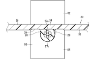
ここでは、超音波溶着機80によって電線20Bとシート材30Bとを超音波溶着することによってワイヤーハーネス10を製造する。ここでは電線20Bは、丸電線である。またシート材30Bは、1層からなる部材であり、電線20Bが配設される電線配設部34Bは平坦面とされている。また超音波溶着機80は、ホーン82及びアンビル84を備える。
Here, the wire harness 10 is manufactured by ultrasonically welding the electric wire 20B and the sheet material 30B with the ultrasonic welding machine 80. Here, the electric wire 20B is a round electric wire. Further, the sheet material 30B is a member composed of one layer, and the electric wire arrangement portion 34B where the electric wires 20B are arranged is a flat surface. The ultrasonic welder 80 includes a horn 82 and an anvil 84.
ホーン82は、接触するワークに対して超音波振動を付与する部材である。ホーン82のうちワークに接触する面には、ローレット加工、つまり滑り止めなどを目的として凹凸形状が施されていることも考えられる。アンビル84は、ホーン82に対して反対側からワークを支持する部材である。従って、ワークにおける溶着対象となる一対の部分が、ホーン82及びアンビル84によって挟持された状態で、超音波振動が付与されて溶着される。
The horn 82 is a member that applies ultrasonic vibration to a workpiece that comes into contact. It is also conceivable that the surface of the horn 82 that comes into contact with the workpiece has a concavo-convex shape for the purpose of knurling, that is, for preventing slipping. The anvil 84 is a member that supports the workpiece from the opposite side with respect to the horn 82. Therefore, in a state where the pair of parts to be welded in the workpiece are sandwiched between the horn 82 and the anvil 84, ultrasonic vibration is applied and the workpiece is welded.
具体的には、超音波溶着を行うに当たってまずは電線20Bを、樹脂製のシート材30Bにおいて絶縁被覆26Bと同じかそれよりも硬く形成されている電線配設部34Bに配設しつつ、電線20Bと電線配設部34Bとを挟持部材によって挟持する。例えば図4に示すように、溶着前の電線20Bを溶着前のシート材30Bの主面33上の所定の位置(電線配設部34B)に配設しつつ、アンビル84によって支持する。この状態で、アンビル84に向けてホーン82を接近させて、ホーン82及びアンビル84によって電線20B及びシート材30Bを挟持し、絶縁被覆26Bと電線配設部34Bとを接触させる。このようにここではホーン82がシート材30B側を押え、アンビル84が電線20B側を押えるように配置されているが、ホーンが電線20B側を押え、アンビルがシート材30B側を押えるように配置されている場合も考えられる。
Specifically, when performing ultrasonic welding, first, the electric wire 20B is disposed on the electric wire arrangement portion 34B formed on the resin sheet material 30B that is the same as or harder than the insulating coating 26B. And the electric wire arrangement part 34B are clamped by a clamping member. For example, as shown in FIG. 4, the electric wire 20B before welding is supported by the anvil 84 while being arranged at a predetermined position (electric wire arrangement part 34B) on the main surface 33 of the sheet material 30B before welding. In this state, the horn 82 is approached toward the anvil 84, the electric wire 20B and the sheet material 30B are sandwiched by the horn 82 and the anvil 84, and the insulating coating 26B and the electric wire arrangement portion 34B are brought into contact with each other. As described above, the horn 82 is arranged to hold the sheet material 30B side and the anvil 84 is arranged to hold the electric wire 20B side, but the horn is arranged to hold the electric wire 20B side and the anvil is pressed to the sheet material 30B side. The case where it is done is also considered.
アンビル84のうちホーン82側を向く面には電線20Bを保持する保持溝85が形成されている。保持溝85の底部は、平面状であってもよいし、湾曲面状であってもよい。図4に示す例では、保持溝85の底部は湾曲面状に形成されている。
A holding groove 85 for holding the electric wire 20B is formed on the surface of the anvil 84 facing the horn 82 side. The bottom of the holding groove 85 may be flat or curved. In the example shown in FIG. 4, the bottom of the holding groove 85 is formed in a curved surface shape.
ここでは保持溝85の深さ寸法が電線20Bの直径と同程度に(図4に示す例では電線20Bの直径よりも僅かに小さく)設定されていることによって、保持溝85を構成する壁部86の先端部が、ホーン82との間でシート材30Bのうち電線20Bの未配設部分をホーン82と共に挟持する押え部89として機能する。
Here, the depth of the holding groove 85 is set to be approximately the same as the diameter of the electric wire 20B (slightly smaller than the diameter of the electric wire 20B in the example shown in FIG. 4). The distal end portion of 86 functions as a presser portion 89 that holds the undisposed portion of the electric wire 20 </ b> B together with the horn 82 in the sheet material 30 </ b> B with the horn 82.
またここでは保持溝85の湾曲面状に形成された底部よりも開口部側は、幅が一定とされている。このため、保持溝85の底部から押え部89の先端に至る壁部86の内面は垂直面87とされている。
Further, here, the width of the opening side of the holding groove 85 is set to be constant with respect to the curved surface. For this reason, the inner surface of the wall 86 extending from the bottom of the holding groove 85 to the tip of the presser 89 is a vertical surface 87.
ここで上述したようにワイヤーハーネス10を車両の狭い隙間に配設するとの観点から言うと、ワイヤーハーネス10は薄い方が好ましい。このため、この観点から言うとシート材30Bが薄い方が好ましい。ここでは溶着前のシート材30Bの厚み寸法は、電線20Bの直径よりも小さく設定されている。もちろん、溶着前のシート材30Bの厚み寸法は、電線20Bの直径と同じであってもよいし、電線20Bの直径よりも大きく設定されていてもよい。
From the viewpoint of arranging the wire harness 10 in a narrow gap of the vehicle as described above, the wire harness 10 is preferably thin. For this reason, from this viewpoint, the sheet material 30B is preferably thin. Here, the thickness dimension of the sheet material 30B before welding is set smaller than the diameter of the electric wire 20B. Of course, the thickness dimension of the sheet material 30B before welding may be the same as the diameter of the electric wire 20B, or may be set larger than the diameter of the electric wire 20B.
特にここでは溶着前のシート材30Bの厚み寸法は、電線20Bの半径よりも小さく設定されている。もちろん、溶着前のシート材30Bの厚み寸法は、電線20Bの半径と同じであってもよいし、電線20Bの半径よりも大きく設定されていてもよい。
Particularly here, the thickness dimension of the sheet material 30B before welding is set smaller than the radius of the electric wire 20B. Of course, the thickness dimension of the sheet material 30B before welding may be the same as the radius of the electric wire 20B, or may be set larger than the radius of the electric wire 20B.
なおここでは溶着前のシート材30Bの厚み寸法は、絶縁被覆26Bの厚み寸法(ここでは複数の素線23が存在することに鑑みた平均の厚み寸法)よりも大きく設定されている。もちろん、溶着前のシート材30Bの厚み寸法は、絶縁被覆26Bの厚み寸法と同じであってもよいし、絶縁被覆26Bの厚み寸法よりも小さく設定されていてもよい。
Here, the thickness dimension of the sheet material 30B before welding is set to be larger than the thickness dimension of the insulating coating 26B (here, the average thickness dimension in view of the presence of the plurality of strands 23). Of course, the thickness dimension of the sheet material 30B before welding may be the same as the thickness dimension of the insulating coating 26B, or may be set smaller than the thickness dimension of the insulating coating 26B.
次に、電線20Bと電線配設部34Bとが挟持部材によって挟持された状態で、絶縁被覆26と電線配設部34Bとを超音波溶着する。ここでは、絶縁被覆26B及びシート材30Bが接触する部分をホーン82及びアンビル84によって挟持した状態で、ホーン82によって超音波振動を付与する。ここではホーン82がシート材30B側を押えるため、シート材30B側から超音波振動を付与する。絶縁被覆26B及びシート材30Bが接触する部分において超音波振動に起因する摩擦熱が生じ、少なくとも一方が溶融することによって、両者が接合される。ここでは絶縁被覆26B及びシート材30Bが共にPVCをベースとした材料で形成されているため、両者が溶融して接合される。
Next, the insulation coating 26 and the electric wire arrangement part 34B are ultrasonically welded in a state where the electric wire 20B and the electric wire arrangement part 34B are held by the holding member. Here, ultrasonic vibration is applied by the horn 82 in a state where the portion where the insulating coating 26B and the sheet material 30B are in contact with each other is sandwiched by the horn 82 and the anvil 84. Here, since the horn 82 presses the sheet material 30B side, ultrasonic vibration is applied from the sheet material 30B side. Friction heat resulting from ultrasonic vibration is generated at the portion where the insulating coating 26B and the sheet material 30B are in contact with each other, and at least one of them is melted to join them. Here, since both the insulation coating 26B and the sheet material 30B are formed of a PVC-based material, both are melted and joined.
超音波溶着が行われている時点で、電線配設部34Bが絶縁被覆26Bと同じかそれよりも硬い状態となっている。特にここでは、絶縁被覆26B及び電線配設部34Bが共にPVC及び可塑剤を含む材料によって形成されている。また超音波溶着が開始される前の時点で、電線配設部34Bを含む部分を構成するPVCに対する可塑剤の割合が、絶縁被覆26を構成するPVCに対する可塑剤の割合と同じかそれよりも低い。そしてこの状態が、超音波溶着が行われている時点においても継続されることによって、超音波溶着が行われている時点で、電線配設部34Bを含む部分が絶縁被覆26Bと同じかそれよりも硬い状態となっている。
At the time when ultrasonic welding is performed, the electric wire arrangement part 34B is in the same or harder state than the insulating coating 26B. In particular, here, both the insulation coating 26B and the electric wire arrangement portion 34B are formed of a material containing PVC and a plasticizer. In addition, at the time before the ultrasonic welding is started, the ratio of the plasticizer to the PVC constituting the portion including the electric wire arranging portion 34B is equal to or higher than the ratio of the plasticizer to the PVC constituting the insulating coating 26. Low. This state is continued even at the time when ultrasonic welding is performed, and at the time when ultrasonic welding is performed, the portion including the electric wire arranging portion 34B is the same as or more than the insulating coating 26B. Is in a hard state.
超音波溶着が行われている時点で、電線配設部34Bを含む部分が絶縁被覆26Bと同じかそれよりも硬い状態となっていることによって、電線配設部34Bと絶縁被覆26Bとの接触部分においてホーン82及びアンビル84による加圧に係る力が絶縁被覆26Bを変形させる力として作用しやすい。これにより電線配設部34Bが溶着されてできた電線固定部34と絶縁被覆26との境界面が、絶縁被覆26のもともとの外周面である円周面形状よりも溶着前の電線配設部34Bの主面33の形状に近い形状に形成される。
When the ultrasonic welding is performed, the portion including the electric wire arrangement portion 34B is in the same or harder state as the insulating coating 26B, so that the electric wire arrangement portion 34B and the insulating coating 26B are in contact with each other. In this portion, the force applied by the horn 82 and the anvil 84 is likely to act as a force for deforming the insulating coating 26B. As a result, the boundary between the electric wire fixing portion 34 and the insulating coating 26 formed by welding the electric wire arranging portion 34B is less than the circumferential surface shape that is the original outer peripheral surface of the insulating coating 26 before the electric wire arranging portion. It is formed in a shape close to the shape of the main surface 33 of 34B.
なお、絶縁被覆26のもともとの外周面である円周面形状は、例えば電線20の長手方向に沿って溶着されない部分がある場合には、その部分で確認することができる。またここでは電線20のうち長手方向に沿って溶着される部分においても、溶着される側の面とは反対側の面では、溶着された際に形状が崩れにくいため、この面において円周面形状を確認することもできる。
In addition, the circumferential surface shape which is the original outer peripheral surface of the insulation coating 26 can be confirmed in the portion where there is a portion that is not welded along the longitudinal direction of the electric wire 20, for example. Further, here, even in the portion welded along the longitudinal direction of the electric wire 20, the surface opposite to the surface to be welded is not easily deformed when welded. The shape can also be confirmed.
なお図4に示すように溶着前の状態で、電線20とシート材30との間には接触する部分の側方で隙間Sが生じている。ここでは図5に示すように溶着時に軟化した絶縁被覆26がこの隙間Sに流れる。従って、ワイヤーハーネス10においては、この隙間Sは、絶縁被覆26の変形部28によって埋められている。このとき、アンビル84の保持溝85の内面が隙間Sの外方を塞ぐように位置している。このため、溶着時に軟化した絶縁被覆26がアンビル84の保持溝85の内面に堰き止められることによって、絶縁被覆26の変形部28の外面は、アンビル84の保持溝85の内面に沿った形状とされる。ここではアンビル84の保持溝85の内面が垂直面87であるため、変形部28の外面はこの垂直面87に応じた垂直面28aとされている。
In addition, as shown in FIG. 4, in the state before welding, the clearance gap S has arisen in the side of the part which contacts between the electric wire 20 and the sheet | seat material 30. FIG. Here, as shown in FIG. 5, the insulating coating 26 softened during welding flows into the gap S. Therefore, in the wire harness 10, the gap S is filled with the deformed portion 28 of the insulating coating 26. At this time, the inner surface of the holding groove 85 of the anvil 84 is positioned so as to close the outside of the gap S. Therefore, the outer surface of the deformed portion 28 of the insulating coating 26 is shaped along the inner surface of the holding groove 85 of the anvil 84 by damming the insulating coating 26 softened during welding on the inner surface of the holding groove 85 of the anvil 84. Is done. Here, since the inner surface of the holding groove 85 of the anvil 84 is the vertical surface 87, the outer surface of the deformed portion 28 is a vertical surface 28 a corresponding to the vertical surface 87.
この変形部28のうちシート材30から遠い部分(第2被覆部分27b側部分)において、もともとの絶縁被覆26との間に界面29が生じている場合もあり得る。例えば超音波溶着時に変形部28にかかるエネルギーが小さい場合などの理由により、もともとの絶縁被覆26部分が融けるに至らない場合に、当該界面29が生じることが考えられる。もちろん超音波溶着時に変形部28にかかるエネルギーが大きい場合などにもともとの絶縁被覆26部分が融けるなどして、界面29が形成されない場合もあり得る。
In the deformed portion 28, a portion far from the sheet material 30 (second covering portion 27b side portion) may have an interface 29 with the original insulating coating 26. For example, the interface 29 may be generated when the original insulating coating 26 portion does not melt due to a small energy applied to the deformed portion 28 during ultrasonic welding. Of course, when the energy applied to the deformed portion 28 during ultrasonic welding is large, the original insulating coating 26 portion may melt, and the interface 29 may not be formed.
また、溶着後のシート材30の主面33において押え部89に押さえられた部分に凹部39が形成されることもあり得る。もちろん凹部39が形成されない場合もあり得る。
Further, the concave portion 39 may be formed in a portion pressed by the presser portion 89 on the main surface 33 of the sheet material 30 after welding. Of course, the recess 39 may not be formed.
<効果等>
以上のように構成されたワイヤーハーネス10によると、第1被覆部分27aの厚み寸法Aが第2被覆部分27bの厚み寸法Bよりも小さくなった分、ワイヤーハーネス10を薄型化できる。このとき、薄くなった第1被覆部分27aの絶縁性能についてはシート材30で補うことができる。 <Effects>
According to thewire harness 10 configured as described above, the wire harness 10 can be thinned by the amount that the thickness dimension A of the first covering portion 27a is smaller than the thickness dimension B of the second covering portion 27b. At this time, the insulation performance of the thinned first covering portion 27 a can be supplemented by the sheet material 30.
以上のように構成されたワイヤーハーネス10によると、第1被覆部分27aの厚み寸法Aが第2被覆部分27bの厚み寸法Bよりも小さくなった分、ワイヤーハーネス10を薄型化できる。このとき、薄くなった第1被覆部分27aの絶縁性能についてはシート材30で補うことができる。 <Effects>
According to the
またシート材30のうち第1被覆部分27aが溶着された部分の厚み寸法Cと第1被覆部分27aの厚み寸法Aとの和が、第2被覆部分27bの厚み寸法B以上に形成されているため、芯線22に対して第1被覆部分27a側の絶縁性を高められる。
Further, the sum of the thickness dimension C of the sheet material 30 where the first covering portion 27a is welded and the thickness dimension A of the first covering portion 27a is formed to be equal to or greater than the thickness dimension B of the second covering portion 27b. Therefore, the insulation on the first covering portion 27a side with respect to the core wire 22 can be enhanced.
また絶縁被覆26とシート材30との溶着部分の境界面における幅寸法Eが、電線20の芯線22を通る部分における幅寸法Fよりも大寸に形成されているため、溶着にかかる接合強度を高めることができる。
Moreover, since the width dimension E at the boundary surface of the welded portion between the insulating coating 26 and the sheet material 30 is formed larger than the width dimension F at the portion passing through the core wire 22 of the electric wire 20, the bonding strength for welding is increased. Can be increased.
また電線固定部34を含む部分が絶縁被覆26と同じかそれより硬く形成されているため、第1被覆部分27aの厚み寸法を第2被覆部分27bの厚み寸法よりも小さくすることが容易となる。
Further, since the portion including the wire fixing portion 34 is formed to be the same as or harder than the insulating coating 26, it is easy to make the thickness dimension of the first covering portion 27a smaller than the thickness dimension of the second covering portion 27b. .
また自動車用電線の絶縁被覆26の材料として一般的なポリ塩化ビニルを用いた場合でも、可塑剤の割合を調節することによって、電線配設部34B及び電線固定部34を絶縁被覆26よりも硬く形成することができる。
Even when general polyvinyl chloride is used as the material for the insulation coating 26 of the automobile wire, the wire arrangement portion 34B and the wire fixing portion 34 are harder than the insulation coating 26 by adjusting the ratio of the plasticizer. Can be formed.
なお、ここでは可塑剤を用いてシート材30と絶縁被覆26との柔らかさを調節している。ここで可塑剤は時間経過等により接触する部材に移行する場合があることが知られている。このため、超音波溶着後においては、電線固定部34と絶縁被覆26との間で可塑剤の移行が生じる場合がある。この場合、溶着直後において、電線固定部34が絶縁被覆26より硬い場合でも、電線固定部34の可塑剤と絶縁被覆26の可塑剤とが平衡状態となり、電線固定部34と絶縁被覆26とが同じ硬さとなることも考えられる。このほか、超音波溶着後の加工(例えば、電線20と電線固定部34とのうち電線固定部34のみを加熱プレスする等)によって絶縁被覆26が電線固定部34よりも硬くされていることもあり得る。これらの場合でも電線固定部34と絶縁被覆26との境界面は主面33に沿った形状のままであることが考えられる。
Here, the softness of the sheet material 30 and the insulating coating 26 is adjusted using a plasticizer. Here, it is known that the plasticizer may move to a contact member over time. For this reason, after ultrasonic welding, the plasticizer may be transferred between the wire fixing portion 34 and the insulating coating 26. In this case, immediately after welding, even if the wire fixing portion 34 is harder than the insulating coating 26, the plasticizer of the wire fixing portion 34 and the plasticizer of the insulating coating 26 are in an equilibrium state, and the electric wire fixing portion 34 and the insulating coating 26 are in contact with each other. The same hardness can be considered. In addition, the insulating coating 26 may be harder than the wire fixing portion 34 by processing after ultrasonic welding (for example, only the wire fixing portion 34 of the electric wire 20 and the wire fixing portion 34 is heated and pressed). possible. Even in these cases, it is considered that the boundary surface between the wire fixing portion 34 and the insulating coating 26 remains in the shape along the main surface 33.
また超音波溶着時の摩擦熱により加熱された温度、および加圧状態でシート材30が絶縁被覆26と同じかそれよりも硬いため、そのまま溶着を進めたときに、絶縁被覆26のうちシート材30側の部分がシート材30と同じかそれよりも変形しやすい。このため、絶縁被覆26の厚みが一様な電線20を用いても、絶縁被覆26のうち芯線22に対してシート材30側の部分をその反対側の部分よりも薄くすることができる。
Further, since the sheet material 30 is the same as or harder than the insulating coating 26 in the temperature heated by the frictional heat at the time of ultrasonic welding and under pressure, the sheet material of the insulating coating 26 when the welding is proceeded as it is. The portion on the 30 side is the same as or easier to deform than the sheet material 30. For this reason, even if it uses the electric wire 20 with the thickness of the insulation coating 26 uniform, the part by the side of the sheet | seat 30 with respect to the core wire 22 among the insulation coating 26 can be made thinner than the part of the other side.
{変形例}
図6は、変形例に係るワイヤーハーネス110を示す横断面図である。 {Modifications}
FIG. 6 is a cross-sectional view showing awire harness 110 according to a modification.
図6は、変形例に係るワイヤーハーネス110を示す横断面図である。 {Modifications}
FIG. 6 is a cross-sectional view showing a
実施形態において、シート材30が1層であるものとして説明してきたが、このことは必須の構成ではない。変形例に係るワイヤーハーネス110におけるシート材130のように、2層以上である場合も考えられる。
In the embodiment, the sheet material 30 has been described as one layer, but this is not an essential configuration. A case where there are two or more layers, such as the sheet material 130 in the wire harness 110 according to the modification, is also conceivable.
具体的にはシート材130は、上記電線固定層32としての第1層32と、第1層32に積層された第2層40とを含む。第1層32は、電線固定部34を含む部分を構成する材料と同じ材料で一様に形成されている。従って第1層32は、PVCをベースとして絶縁被覆26に添加された可塑剤と同じ可塑剤が添加された材料によって形成されている。そして第1層32を構成するPVCに対する可塑剤の割合が、絶縁被覆26を構成するPVCに対する可塑剤の割合と同じかそれよりも高いことによって第1層32が絶縁被覆26と同じかそれよりも硬く形成されている。
Specifically, the sheet material 130 includes a first layer 32 as the wire fixing layer 32 and a second layer 40 laminated on the first layer 32. The first layer 32 is uniformly formed of the same material as that constituting the portion including the wire fixing portion 34. Therefore, the first layer 32 is formed of a material to which the same plasticizer as the plasticizer added to the insulating coating 26 is added based on PVC. The ratio of the plasticizer to the PVC constituting the first layer 32 is equal to or higher than the ratio of the plasticizer to the PVC constituting the insulating coating 26, so that the first layer 32 is equal to or higher than the insulating coating 26. Is also hard.
第2層40は、第1層32とは異なる物性を有する。より詳細には、第1層32は、第2層40よりも絶縁被覆26との溶着に適した物性を有する部分であり、第2層40は、シート材30の用途などによって必要な物性を有する部分である。
The second layer 40 has physical properties different from those of the first layer 32. More specifically, the first layer 32 is a portion having physical properties that are more suitable for welding with the insulating coating 26 than the second layer 40, and the second layer 40 has physical properties that are necessary depending on the use of the sheet material 30. It is a part that has.
例えば第2層40は、形状保持性の向上を目的として第1層32よりも硬く形成されていることが考えられる。これにより、シート材30が第1層32のみで構成されている場合に比べて、ワイヤーハーネス10を車両に組付ける際のワイヤーハーネス10の取扱性を向上させることができる。また耐摩耗性の向上等を目的として、第2層40が第1層32よりも硬く形成されていることも考えられる。
For example, the second layer 40 may be formed to be harder than the first layer 32 for the purpose of improving shape retention. Thereby, compared with the case where the sheet | seat material 30 is comprised only by the 1st layer 32, the handleability of the wire harness 10 at the time of assembling the wire harness 10 to a vehicle can be improved. It is also conceivable that the second layer 40 is formed to be harder than the first layer 32 for the purpose of improving wear resistance.
このとき第2層40は、第1層32と同じ樹脂をベースとした材料によって第1層32よりも硬く形成されていることが考えられる。ここでは第1層32がPVCをベースとしているため、第2層40のPVCをベースとすることが考えられる。この場合、例えば、第2層40を構成するPVCに対する可塑剤の割合を、第1層32を構成するPVCに対する可塑剤の割合よりも低くすることによって、第2層40を第1層32よりも硬くすることができる。
At this time, it is considered that the second layer 40 is formed to be harder than the first layer 32 by the same resin-based material as the first layer 32. Here, since the first layer 32 is based on PVC, it can be considered that the second layer 40 is based on PVC. In this case, for example, by making the ratio of the plasticizer to the PVC constituting the second layer 40 lower than the ratio of the plasticizer to the PVC constituting the first layer 32, the second layer 40 is made more than the first layer 32. Can also be hardened.
また第2層40は、第1層32とは別の樹脂をベースとした材料によって第1層32よりも硬く形成されていることも考えられる。ここでは第1層32がPVCをベースとしているため、第2層40はPVC以外の樹脂、例えば、PE、ポリプロピレン(PP)、ポリエチレンテレフタレート(PET)などをベースとした材料によって形成されていることが考えられる。
It is also conceivable that the second layer 40 is formed to be harder than the first layer 32 by a material based on a resin different from the first layer 32. Here, since the first layer 32 is based on PVC, the second layer 40 is formed of a material based on a resin other than PVC, for example, PE, polypropylene (PP), polyethylene terephthalate (PET), or the like. Can be considered.
第1層32と第2層40とを有するシート材30の形成方法は、特に限定されるものではないが、例えば、一度の押出工程で積層構造を実現する共押出法で形成されたり、第1層32と第2層40とが一旦別々にシート状に成形された後に相互に貼り合わされて一体とされるラミネート法で形成されたりすることが考えられる。
The method for forming the sheet material 30 having the first layer 32 and the second layer 40 is not particularly limited. For example, the sheet material 30 may be formed by a coextrusion method that realizes a laminated structure in a single extrusion process, It is conceivable that the first layer 32 and the second layer 40 may be formed by a laminating method in which the first layer 32 and the second layer 40 are once separately formed into a sheet shape and then bonded together.
また例えば、第2層40としてアルミニウム箔などの金属箔が採用されることによって、シート材130がシールド性を有したり、放熱性を高めたりするように構成されていることが考えられる。また例えば、第2層40として第1層32よりも軟らかい不織布又は発泡樹脂シート等が採用されることによって、シート材130が防音機能を高めるように構成されていることも考えられる。
Further, for example, it is conceivable that the sheet material 130 is configured to have a shielding property or enhance a heat dissipation property by employing a metal foil such as an aluminum foil as the second layer 40. In addition, for example, it is conceivable that the sheet material 130 is configured to enhance the soundproofing function by employing a nonwoven fabric or a foamed resin sheet that is softer than the first layer 32 as the second layer 40.
さらにシート材が3層構造以上であることも考えられる。つまり第2層40に対して第1層32とは反対側に第3層、第4層と順に積層されていることが考えられる。
Furthermore, it is conceivable that the sheet material has a three-layer structure or more. That is, it is conceivable that the third layer and the fourth layer are stacked in this order on the opposite side of the second layer 40 from the first layer 32.
その他、これまで超音波溶着時に絶縁被覆26が円周面形状からシート材30の主面33に近い形状に変形するものとして説明してきたが、このことは必須の構成ではない。例えば、超音波溶着が行われる前に予め絶縁被覆26が円周面形状からシート材30の主面33に近い形状に変形されていてもよい。また例えば、絶縁被覆26が押出成形される際に円周面形状の一部が平坦な形状に押出成形されてもよい。この場合、シート材30が絶縁被覆26よりも軟らかく形成されていてもよい。
In addition, although it has been described so far that the insulating coating 26 is deformed from the circumferential surface shape to a shape close to the main surface 33 of the sheet material 30 during ultrasonic welding, this is not an essential configuration. For example, before the ultrasonic welding is performed, the insulating coating 26 may be deformed from a circumferential surface shape to a shape close to the main surface 33 of the sheet material 30 in advance. Further, for example, when the insulating coating 26 is extruded, a part of the circumferential surface shape may be extruded into a flat shape. In this case, the sheet material 30 may be formed softer than the insulating coating 26.
またこれまでシート材30のうち第1被覆部分27aが溶着された部分の厚み寸法Cと第1被覆部分27aの厚み寸法Aとの和が、第2被覆部分27bの厚み寸法B以上に形成されているものとして説明してきたが、このことは必須の構成ではない。シート材30のうち第1被覆部分27aが溶着された部分の厚み寸法Cと第1被覆部分27aの厚み寸法Aとの和が、第2被覆部分27bの厚み寸法Bより小さく形成されている場合もあり得る。この場合、シート材30の絶縁性能が絶縁被覆26の絶縁性能よりも高いことが好ましい。つまり、厚み寸法Cと厚み寸法Aとの和は、第2被覆部27bと同等以上の絶縁性能を有すれば、厚み寸法Bよりも小さくてもよい。
In addition, the sum of the thickness dimension C of the portion of the sheet material 30 where the first covering portion 27a has been welded and the thickness dimension A of the first covering portion 27a is greater than or equal to the thickness dimension B of the second covering portion 27b. However, this is not an essential configuration. When the sum of the thickness dimension C of the sheet material 30 where the first covering portion 27a is welded and the thickness dimension A of the first covering portion 27a is smaller than the thickness dimension B of the second covering portion 27b. There is also a possibility. In this case, the insulating performance of the sheet material 30 is preferably higher than the insulating performance of the insulating coating 26. That is, the sum of the thickness dimension C and the thickness dimension A may be smaller than the thickness dimension B as long as it has an insulation performance equal to or higher than that of the second covering portion 27b.
またこれまで絶縁被覆26とシート材30との溶着部分の境界面における幅寸法Eが、電線20の芯線22を通る部分における幅寸法Fよりも大寸に形成されているものとして説明してきたが、このことは必須の構成ではない。絶縁被覆26とシート材30との溶着部分の境界面における幅寸法Eが、電線20の芯線22を通る部分における幅寸法F以下とされていることもかんがえられる。例えば、超音波溶着時の圧力を小さくしたり、付与する振動エネルギーを小さくしたりすることによって、溶着部分を小さくすることができる。
Moreover, although the width dimension E in the boundary surface of the welding part of the insulating coating 26 and the sheet material 30 has been described so far as being formed larger than the width dimension F in the part passing through the core wire 22 of the electric wire 20. This is not an essential configuration. It can also be understood that the width dimension E at the boundary surface of the welded portion between the insulating coating 26 and the sheet material 30 is equal to or less than the width dimension F at the portion passing through the core wire 22 of the electric wire 20. For example, the welding portion can be reduced by reducing the pressure during ultrasonic welding or by reducing the vibration energy to be applied.
またこれまで電線20が丸電線であるものとして説明してきたが、このことは必須の構成ではない。電線20は、例えば角電線などの丸電線以外の電線が採用される場合もあり得る。
In addition, the electric wire 20 has been described as a round electric wire so far, but this is not an essential configuration. The electric wire 20 may be an electric wire other than a round electric wire such as a square electric wire.
またこれまで絶縁被覆26及び電線固定層32がPVCをベースとした材料によって形成されているものとして説明してきたが、このことは必須の構成ではない。例えば絶縁被覆26及び電線固定層32がPE又はPPをベースとした材料によって形成されていることもあり得る。この場合、絶縁被覆26のベースとなるPE又はPPを電線固定層32のベースとなるPE又はPPと同じかそれよりも低密度化したり、絶縁被覆26のベースとなるPE又はPPにイソブチレンなどと反応させたりすることによって、電線固定層32を絶縁被覆26と同じかそれよりも硬くすることができる。
In addition, although it has been described so far that the insulating coating 26 and the wire fixing layer 32 are formed of a PVC-based material, this is not an essential configuration. For example, the insulating coating 26 and the wire fixing layer 32 may be formed of a material based on PE or PP. In this case, the density of the PE or PP used as the base of the insulating coating 26 is reduced to the same or lower density than the PE or PP used as the base of the electric wire fixing layer 32, or isobutylene or the like By making it react, the electric wire fixing layer 32 can be made the same as or harder than the insulating coating 26.
またこれまで変形部28の外面がアンビル84の内面に沿った形状となるものとして説明してきたが、このことは必須の構成ではない。例えば、アンビル84に保持溝85が形成されていない場合、または保持溝85が浅く形成されている場合に変形部28の外面はアンビル84の内面に沿った形状とならないことがあり得る。この場合、変形部28は、シート材30の主面33に沿って広がり易くなり、この結果、上記寸法Eが図3に示されるものよりも大きくなることが考えられる。
In addition, although it has been described so far that the outer surface of the deformed portion 28 has a shape along the inner surface of the anvil 84, this is not an essential configuration. For example, when the holding groove 85 is not formed in the anvil 84 or when the holding groove 85 is formed shallow, the outer surface of the deformable portion 28 may not have a shape along the inner surface of the anvil 84. In this case, the deformed portion 28 is likely to spread along the main surface 33 of the sheet material 30, and as a result, the dimension E may be larger than that shown in FIG. 3.
なお、上記実施形態及び各変形例で説明した各構成は、相互に矛盾しない限り適宜組み合わせることができる。
In addition, each structure demonstrated in the said embodiment and each modification can be suitably combined unless it mutually contradicts.
以上のようにこの発明は詳細に説明されたが、上記した説明は、すべての局面において、例示であって、この発明がそれに限定されるものではない。例示されていない無数の変形例が、この発明の範囲から外れることなく想定され得るものと解される。
Although the present invention has been described in detail as described above, the above description is illustrative in all aspects, and the present invention is not limited thereto. It is understood that countless variations that are not illustrated can be envisaged without departing from the scope of the present invention.
10 ワイヤーハーネス
20 電線
22 芯線
23 素線
26 絶縁被覆
27a 第1被覆部分
27b 第2被覆部分
30 シート材
32 第1層(電線固定層)
33 主面
34 電線固定部
34B 電線配設部
36 電線未配設部
40 第2層
80 超音波溶着機
82 ホーン
84 アンビル
85 保持溝 DESCRIPTION OFSYMBOLS 10 Wire harness 20 Electric wire 22 Core wire 23 Elementary wire 26 Insulation coating 27a 1st coating | coated part 27b 2nd coating | coated part 30 Sheet material 32 1st layer (electric wire fixing layer)
33Main surface 34 Electric wire fixing part 34B Electric wire arrangement part 36 Electric wire non-arrangement part 40 Second layer 80 Ultrasonic welding machine 82 Horn 84 Anvil 85 Holding groove
20 電線
22 芯線
23 素線
26 絶縁被覆
27a 第1被覆部分
27b 第2被覆部分
30 シート材
32 第1層(電線固定層)
33 主面
34 電線固定部
34B 電線配設部
36 電線未配設部
40 第2層
80 超音波溶着機
82 ホーン
84 アンビル
85 保持溝 DESCRIPTION OF
33
Claims (7)
- 芯線と前記芯線を覆う絶縁被覆とを含む電線と、
樹脂製の主面上に前記電線が配設されており、前記主面において前記電線と接触する部分が前記電線の前記絶縁被覆と溶着されて電線固定部に形成されているシート材と、
を備え、
前記絶縁被覆のうち前記芯線に対して前記電線固定部側の第1被覆部分の厚み寸法が、その反対側の第2被覆部分の厚み寸法よりも小寸に形成されている、ワイヤーハーネス。 An electric wire including a core wire and an insulating coating covering the core wire;
The electric wire is disposed on a main surface made of resin, and a portion of the main surface that comes into contact with the electric wire is welded to the insulating coating of the electric wire and is formed in the electric wire fixing portion, and
With
The wire harness in which the thickness dimension of the 1st coating | coated part by the side of the said electric wire fixing | fixed part is formed smaller than the thickness dimension of the 2nd coating | coated part of the other side with respect to the said core wire among the said insulation coating. - 請求項1に記載のワイヤーハーネスであって、
前記シート材のうち前記第1被覆部分が溶着された部分の厚み寸法と前記第1被覆部分の厚み寸法との和が、前記第2被覆部分の厚み寸法以上に形成されている、ワイヤーハーネス。 The wire harness according to claim 1,
The wire harness in which the sum of the thickness dimension of the part by which the said 1st coating | coated part was welded among the said sheet | seat materials and the thickness dimension of the said 1st coating | coated part is formed more than the thickness dimension of the said 2nd coating | coated part. - 請求項1又は請求項2に記載のワイヤーハーネスであって、
前記絶縁被覆と前記シート材との溶着部分の境界面における幅寸法が、前記電線のうち前記芯線の中心を通る部分における幅寸法よりも大寸に形成されている、ワイヤーハーネス。 The wire harness according to claim 1 or 2,
The wire harness in which the width dimension in the boundary surface of the welding part of the said insulation coating and the said sheet | seat material is formed larger than the width dimension in the part which passes along the center of the said core wire among the said electric wires. - 請求項1から請求項3のいずれか1項に記載のワイヤーハーネスであって、
前記電線固定部を含む部分が前記絶縁被覆と同じかそれより硬く形成されている、ワイヤーハーネス。 The wire harness according to any one of claims 1 to 3,
A wire harness in which a portion including the electric wire fixing portion is formed to be the same as or harder than the insulating coating. - 請求項4に記載のワイヤーハーネスであって、
前記絶縁被覆及び前記電線固定部が共にポリ塩化ビニル及び可塑剤を含む材料によって形成され、
前記電線固定部を含む部分を構成するポリ塩化ビニルに対する可塑剤の割合が、前記絶縁被覆を構成するポリ塩化ビニルに対する可塑剤の割合と同じかそれよりも低いことによって前記電線固定部を含む部分が前記絶縁被覆と同じかそれよりも硬く形成されている、ワイヤーハーネス。 The wire harness according to claim 4,
Both the insulating coating and the wire fixing part are formed of a material containing polyvinyl chloride and a plasticizer,
The portion including the electric wire fixing portion when the ratio of the plasticizer to the polyvinyl chloride constituting the portion including the electric wire fixing portion is equal to or lower than the ratio of the plasticizer to the polyvinyl chloride constituting the insulating coating. The wire harness is formed to be the same as or harder than the insulating coating. - (a)芯線と前記芯線を覆う絶縁被覆とを含む電線を、シート材における樹脂製の電線配設部に配設しつつ、前記電線と前記電線配設部とを挟持部材によって挟持する工程と、
(b)前記工程(a)の後で、前記絶縁被覆と前記電線配設部とを超音波溶着する工程と、
を備え、
前記工程(b)が行われている時点で、前記電線配設部を含む部分が前記絶縁被覆と同じかそれよりも硬い状態となっている、ワイヤーハーネスの製造方法。 (A) a step of sandwiching the electric wire and the electric wire arrangement portion by a holding member while arranging an electric wire including a core wire and an insulating coating covering the core wire in a resin electric wire arrangement portion in the sheet material; ,
(B) After the step (a), the step of ultrasonically welding the insulating coating and the wire arrangement portion;
With
The method for manufacturing a wire harness, wherein the portion including the electric wire arrangement portion is in the same or harder state as the insulating coating when the step (b) is performed. - 請求項6に記載のワイヤーハーネスの製造方法であって、
前記絶縁被覆及び前記電線配設部が共にポリ塩化ビニル及び可塑剤を含む材料によって形成され、
前記工程(b)が行われている時点で、前記電線配設部を含む部分を構成するポリ塩化ビニルに対する可塑剤の割合が、前記絶縁被覆を構成するポリ塩化ビニルに対する可塑剤の割合と同じかそれよりも低いことによって、前記電線配設部を含む部分が前記絶縁被覆と同じかそれよりも硬い状態となっている、ワイヤーハーネスの製造方法。 It is a manufacturing method of the wire harness of Claim 6, Comprising:
Both the insulating coating and the electric wire arrangement part are formed of a material containing polyvinyl chloride and a plasticizer,
At the time when the step (b) is performed, the ratio of the plasticizer to the polyvinyl chloride constituting the portion including the electric wire arrangement portion is the same as the ratio of the plasticizer to the polyvinyl chloride constituting the insulating coating. The method of manufacturing a wire harness in which the portion including the electric wire arrangement portion is in the same or harder state than the insulating coating by being lower than that.
Priority Applications (3)
| Application Number | Priority Date | Filing Date | Title |
|---|---|---|---|
| CN201880091664.XA CN111902886B (en) | 2018-03-30 | 2018-08-22 | Wire harness and method for manufacturing wire harness |
| US17/043,105 US11501898B2 (en) | 2018-03-30 | 2018-08-22 | Wire harness and method of manufacturing wire harness |
| DE112018007407.2T DE112018007407T5 (en) | 2018-03-30 | 2018-08-22 | CABLE STRING AND METHOD FOR MANUFACTURING A CABLE STRING |
Applications Claiming Priority (2)
| Application Number | Priority Date | Filing Date | Title |
|---|---|---|---|
| JP2018-067192 | 2018-03-30 | ||
| JP2018067192A JP6665882B2 (en) | 2018-03-30 | 2018-03-30 | Wire harness and method of manufacturing wire harness |
Publications (1)
| Publication Number | Publication Date |
|---|---|
| WO2019187196A1 true WO2019187196A1 (en) | 2019-10-03 |
Family
ID=68058061
Family Applications (1)
| Application Number | Title | Priority Date | Filing Date |
|---|---|---|---|
| PCT/JP2018/030915 WO2019187196A1 (en) | 2018-03-30 | 2018-08-22 | Wire harness and wire harness production method |
Country Status (5)
| Country | Link |
|---|---|
| US (1) | US11501898B2 (en) |
| JP (1) | JP6665882B2 (en) |
| CN (1) | CN111902886B (en) |
| DE (1) | DE112018007407T5 (en) |
| WO (1) | WO2019187196A1 (en) |
Cited By (1)
| Publication number | Priority date | Publication date | Assignee | Title |
|---|---|---|---|---|
| US20210118590A1 (en) * | 2018-03-28 | 2021-04-22 | Autonetworks Technologies, Ltd. | Wire harness and method of manufacturing wire harness |
Families Citing this family (2)
| Publication number | Priority date | Publication date | Assignee | Title |
|---|---|---|---|---|
| US10639737B1 (en) * | 2018-10-19 | 2020-05-05 | Aptiv Technologies Limited | Welding system and method |
| CN116529972A (en) * | 2021-01-20 | 2023-08-01 | 古河电气工业株式会社 | Joint structure, method for manufacturing same, and wire outer package |
Citations (3)
| Publication number | Priority date | Publication date | Assignee | Title |
|---|---|---|---|---|
| JP2002050236A (en) * | 2000-08-07 | 2002-02-15 | Yazaki Corp | Conductive thin film sheet with wire and method of making the same |
| JP2003257513A (en) * | 2002-02-27 | 2003-09-12 | Yazaki Corp | Connecting method and structure of coated wire |
| JP2015090783A (en) * | 2013-11-05 | 2015-05-11 | 住友電装株式会社 | Wire harness |
Family Cites Families (18)
| Publication number | Priority date | Publication date | Assignee | Title |
|---|---|---|---|---|
| US3857995A (en) * | 1972-11-24 | 1974-12-31 | Amp Inc | Electrical connector |
| JPS5141910B2 (en) * | 1972-12-12 | 1976-11-12 | ||
| JPS5054597A (en) | 1973-09-06 | 1975-05-14 | ||
| JPS5054597U (en) * | 1973-09-14 | 1975-05-24 | ||
| JPH0636330B2 (en) * | 1985-06-17 | 1994-05-11 | 矢崎総業株式会社 | Wire-harness manufacturing method |
| US6578263B2 (en) * | 1996-06-04 | 2003-06-17 | Yazaki Corporation | Method of manufacturing a wire harness |
| JP2001505706A (en) * | 1996-10-18 | 2001-04-24 | ダブリュ.エル.ゴア アンド アソシエイツ,インコーポレイティド | Ultra small and flat signal transmission cable |
| JP4504529B2 (en) * | 2000-08-07 | 2010-07-14 | 矢崎総業株式会社 | How to connect wires |
| JP2002080819A (en) * | 2000-09-06 | 2002-03-22 | Tentac Co Ltd | Heat-bonded film |
| JP2002216871A (en) | 2001-01-19 | 2002-08-02 | Yazaki Corp | Conductor thin film sheet with electric cable, and manufacturing method of the same |
| JP4914539B2 (en) | 2001-05-18 | 2012-04-11 | 矢崎総業株式会社 | Assembly method of shield harness |
| EP2547724B1 (en) * | 2010-03-17 | 2015-11-11 | ExxonMobil Chemical Patents Inc. | Plasticiser blends and compositions and articles made therefrom |
| JP5441826B2 (en) * | 2010-06-14 | 2014-03-12 | 株式会社オートネットワーク技術研究所 | Anticorrosive, coated electric wire with terminal and wire harness |
| JP5900407B2 (en) * | 2012-11-08 | 2016-04-06 | 住友電装株式会社 | Wire harness |
| JP5904106B2 (en) * | 2012-11-30 | 2016-04-13 | 日立金属株式会社 | Cable connector, cable assembly, and method of manufacturing cable assembly |
| CN104936999B (en) * | 2013-01-16 | 2017-06-20 | 株式会社自动网络技术研究所 | Curing materials, wire harness and its manufacture method |
| DE112014001580T5 (en) * | 2013-03-22 | 2015-12-03 | Autonetworks Technologies, Ltd. | Jacketed electrical wire with a clamp |
| JP5979113B2 (en) | 2013-10-03 | 2016-08-24 | 住友電装株式会社 | Wire harness |
-
2018
- 2018-03-30 JP JP2018067192A patent/JP6665882B2/en active Active
- 2018-08-22 US US17/043,105 patent/US11501898B2/en active Active
- 2018-08-22 CN CN201880091664.XA patent/CN111902886B/en active Active
- 2018-08-22 DE DE112018007407.2T patent/DE112018007407T5/en active Pending
- 2018-08-22 WO PCT/JP2018/030915 patent/WO2019187196A1/en active Application Filing
Patent Citations (3)
| Publication number | Priority date | Publication date | Assignee | Title |
|---|---|---|---|---|
| JP2002050236A (en) * | 2000-08-07 | 2002-02-15 | Yazaki Corp | Conductive thin film sheet with wire and method of making the same |
| JP2003257513A (en) * | 2002-02-27 | 2003-09-12 | Yazaki Corp | Connecting method and structure of coated wire |
| JP2015090783A (en) * | 2013-11-05 | 2015-05-11 | 住友電装株式会社 | Wire harness |
Cited By (2)
| Publication number | Priority date | Publication date | Assignee | Title |
|---|---|---|---|---|
| US20210118590A1 (en) * | 2018-03-28 | 2021-04-22 | Autonetworks Technologies, Ltd. | Wire harness and method of manufacturing wire harness |
| US11521764B2 (en) * | 2018-03-28 | 2022-12-06 | Autonetworks Technologies, Ltd. | Wire harness and method of manufacturing wire harness |
Also Published As
| Publication number | Publication date |
|---|---|
| US11501898B2 (en) | 2022-11-15 |
| US20210027916A1 (en) | 2021-01-28 |
| JP2019179630A (en) | 2019-10-17 |
| JP6665882B2 (en) | 2020-03-13 |
| CN111902886B (en) | 2022-05-03 |
| DE112018007407T5 (en) | 2020-12-10 |
| CN111902886A (en) | 2020-11-06 |
Similar Documents
| Publication | Publication Date | Title |
|---|---|---|
| JP6798471B2 (en) | How to manufacture wire harnesses and wire harnesses | |
| WO2019187196A1 (en) | Wire harness and wire harness production method | |
| JP2018137168A (en) | Wire Harness | |
| WO2018235788A1 (en) | Wiring harness and method for producing wiring harness | |
| WO2016158455A1 (en) | Exterior wire harness | |
| CN107408424B (en) | External wire harness | |
| JP2019179630A5 (en) | ||
| WO2019188080A1 (en) | Wiring harness and method for producing wiring harness | |
| WO2019187193A1 (en) | Wire harness and wire harness production method | |
| JP7192628B2 (en) | Wiring material | |
| JP6923023B2 (en) | Wire harness and wire harness manufacturing method | |
| WO2020039914A1 (en) | Wiring member | |
| JP4591166B2 (en) | Flat cable and manufacturing method thereof | |
| WO2020203252A1 (en) | Wiring member | |
| JP2020092097A5 (en) | ||
| WO2023136216A1 (en) | Wiring member and manufacturing method for wiring member | |
| JP2002237219A (en) | Electric wire with welded layer and method of manufacturing electric wire with welded layer | |
| JP2015015204A (en) | Electric wire with terminal | |
| JP2005312143A (en) | Fixing structure of flat cable |
Legal Events
| Date | Code | Title | Description |
|---|---|---|---|
| 121 | Ep: the epo has been informed by wipo that ep was designated in this application |
Ref document number: 18911902 Country of ref document: EP Kind code of ref document: A1 |
|
| 122 | Ep: pct application non-entry in european phase |
Ref document number: 18911902 Country of ref document: EP Kind code of ref document: A1 |