WO2019176110A1 - 誘導加熱調理器 - Google Patents
誘導加熱調理器 Download PDFInfo
- Publication number
- WO2019176110A1 WO2019176110A1 PCT/JP2018/010610 JP2018010610W WO2019176110A1 WO 2019176110 A1 WO2019176110 A1 WO 2019176110A1 JP 2018010610 W JP2018010610 W JP 2018010610W WO 2019176110 A1 WO2019176110 A1 WO 2019176110A1
- Authority
- WO
- WIPO (PCT)
- Prior art keywords
- heating coil
- heating
- heating coils
- heated
- power
- Prior art date
Links
Images


Classifications
-
- H—ELECTRICITY
- H05—ELECTRIC TECHNIQUES NOT OTHERWISE PROVIDED FOR
- H05B—ELECTRIC HEATING; ELECTRIC LIGHT SOURCES NOT OTHERWISE PROVIDED FOR; CIRCUIT ARRANGEMENTS FOR ELECTRIC LIGHT SOURCES, IN GENERAL
- H05B6/00—Heating by electric, magnetic or electromagnetic fields
- H05B6/02—Induction heating
- H05B6/06—Control, e.g. of temperature, of power
- H05B6/062—Control, e.g. of temperature, of power for cooking plates or the like
- H05B6/065—Control, e.g. of temperature, of power for cooking plates or the like using coordinated control of multiple induction coils
-
- H—ELECTRICITY
- H02—GENERATION; CONVERSION OR DISTRIBUTION OF ELECTRIC POWER
- H02M—APPARATUS FOR CONVERSION BETWEEN AC AND AC, BETWEEN AC AND DC, OR BETWEEN DC AND DC, AND FOR USE WITH MAINS OR SIMILAR POWER SUPPLY SYSTEMS; CONVERSION OF DC OR AC INPUT POWER INTO SURGE OUTPUT POWER; CONTROL OR REGULATION THEREOF
- H02M7/00—Conversion of ac power input into dc power output; Conversion of dc power input into ac power output
- H02M7/42—Conversion of dc power input into ac power output without possibility of reversal
- H02M7/44—Conversion of dc power input into ac power output without possibility of reversal by static converters
- H02M7/48—Conversion of dc power input into ac power output without possibility of reversal by static converters using discharge tubes with control electrode or semiconductor devices with control electrode
- H02M7/53—Conversion of dc power input into ac power output without possibility of reversal by static converters using discharge tubes with control electrode or semiconductor devices with control electrode using devices of a triode or transistor type requiring continuous application of a control signal
- H02M7/537—Conversion of dc power input into ac power output without possibility of reversal by static converters using discharge tubes with control electrode or semiconductor devices with control electrode using devices of a triode or transistor type requiring continuous application of a control signal using semiconductor devices only, e.g. single switched pulse inverters
-
- H—ELECTRICITY
- H05—ELECTRIC TECHNIQUES NOT OTHERWISE PROVIDED FOR
- H05B—ELECTRIC HEATING; ELECTRIC LIGHT SOURCES NOT OTHERWISE PROVIDED FOR; CIRCUIT ARRANGEMENTS FOR ELECTRIC LIGHT SOURCES, IN GENERAL
- H05B6/00—Heating by electric, magnetic or electromagnetic fields
- H05B6/02—Induction heating
- H05B6/10—Induction heating apparatus, other than furnaces, for specific applications
- H05B6/12—Cooking devices
- H05B6/1209—Cooking devices induction cooking plates or the like and devices to be used in combination with them
- H05B6/1245—Cooking devices induction cooking plates or the like and devices to be used in combination with them with special coil arrangements
- H05B6/1272—Cooking devices induction cooking plates or the like and devices to be used in combination with them with special coil arrangements with more than one coil or coil segment per heating zone
-
- H—ELECTRICITY
- H05—ELECTRIC TECHNIQUES NOT OTHERWISE PROVIDED FOR
- H05B—ELECTRIC HEATING; ELECTRIC LIGHT SOURCES NOT OTHERWISE PROVIDED FOR; CIRCUIT ARRANGEMENTS FOR ELECTRIC LIGHT SOURCES, IN GENERAL
- H05B2213/00—Aspects relating both to resistive heating and to induction heating, covered by H05B3/00 and H05B6/00
- H05B2213/05—Heating plates with pan detection means
-
- Y—GENERAL TAGGING OF NEW TECHNOLOGICAL DEVELOPMENTS; GENERAL TAGGING OF CROSS-SECTIONAL TECHNOLOGIES SPANNING OVER SEVERAL SECTIONS OF THE IPC; TECHNICAL SUBJECTS COVERED BY FORMER USPC CROSS-REFERENCE ART COLLECTIONS [XRACs] AND DIGESTS
- Y02—TECHNOLOGIES OR APPLICATIONS FOR MITIGATION OR ADAPTATION AGAINST CLIMATE CHANGE
- Y02B—CLIMATE CHANGE MITIGATION TECHNOLOGIES RELATED TO BUILDINGS, e.g. HOUSING, HOUSE APPLIANCES OR RELATED END-USER APPLICATIONS
- Y02B40/00—Technologies aiming at improving the efficiency of home appliances, e.g. induction cooking or efficient technologies for refrigerators, freezers or dish washers
Definitions
- the present invention relates to an induction cooking device having a plurality of heating coils.
- a conventional induction heating cooker includes a main body having a top plate on which an object to be heated is placed, and a heating coil unit that induction-heats the object to be heated placed on the top plate.
- the heating coil unit at least four heating coils are arranged in a line on the same plane (see, for example, Patent Document 1).
- an induction heating cooker when a liquid food is stored in a heated object such as a pan and heated, a heating operation that promotes convection of the liquid food is performed, so that the temperature of the food is not uniform and It is desired to suppress burning of cooked food.
- Patent Document 1 does not perform any control to generate convection in the cooked food in the heated object. For this reason, when liquid cooking goods are accommodated in a to-be-heated material and heated, there existed a problem that the nonuniformity of the temperature of cooking foods and the burning of cooking foods arise.
- the present invention has been made in order to solve the above-described problems, and can promote convection of a liquid food contained in an object to be heated, unevenness of the temperature of the food, and burning of the food.
- An induction heating cooker that can suppress the above is obtained.
- An induction heating cooker includes a plurality of heating coils arranged in a line on the same plane, a plurality of inverter circuits that supply high-frequency power to the plurality of heating coils, and the plurality of heating coils, respectively.
- a load determination unit that determines the presence or absence of an object to be heated placed above the control unit, and a control device that controls driving of the plurality of inverter circuits based on a determination result of the load determination unit.
- FIG. It is a top view which shows typically the some heating coil of the induction heating cooking appliance which concerns on Embodiment 1.
- FIG. It is a top view explaining arrangement
- FIG. It is a block diagram which shows the structure of the induction heating cooking appliance which concerns on Embodiment 1.
- FIG. It is a top view which shows typically the energization state of the some heating coil of the induction heating cooking appliance which concerns on Embodiment 1.
- FIG. 1 It is a top view which shows typically the energization state of the some heating coil of the induction heating cooking appliance which concerns on Embodiment 1.
- FIG. It is a figure which shows the some heating coil and to-be-heated material of the induction heating cooking appliance which concerns on Embodiment 1.
- FIG. It is a figure which shows the some heating coil and to-be-heated material of the induction heating cooking appliance which concerns on Embodiment 1.
- FIG. It is a top view which shows typically the energization state of the some heating coil of the induction heating cooking appliance which concerns on Embodiment 1.
- FIG. 1 shows typically the energization state of the some heating coil of the induction heating cooking appliance which concerns on Embodiment 1.
- FIG. 1 It is a top view which shows typically the energization state of the some heating coil of the induction heating cooking appliance which concerns on Embodiment 1.
- FIG. It is a figure which shows the some heating coil and to-be-heated material of the induction heating cooking appliance which concerns on Embodiment 1.
- FIG. It is a figure which shows the some heating coil and to-be-heated material of the induction heating cooking appliance which concerns on Embodiment 1.
- FIG. It is a figure which shows the some heating coil and to-be-heated material of the induction heating cooking appliance which concerns on Embodiment 1.
- FIG. It is a top view which shows typically the energization state of the some heating coil of the induction heating cooking appliance which concerns on Embodiment 1.
- FIG. 1 It is a top view which shows typically the energization state of the some heating coil of the induction heating cooking appliance which concerns on Embodiment 1.
- FIG. 2 is a top view which shows typically the energization state of the some heating coil of the induction heating cooking appliance which concerns on Embodiment 1.
- FIG. 2 is a top view which shows typically the energization state of the some heating coil of the induction heating cooking appliance which concerns on Embodiment 1.
- FIG. It is a figure which shows the some heating coil and to-be-heated material of the induction heating cooking appliance which concerns on Embodiment 1.
- FIG. 1 It is a figure which shows the some heating coil and to-be-heated material of the induction heating cooking appliance which concerns on Embodiment 1.
- FIG. 2 is a figure which shows the some heating coil and to-be-heated material of the induction heating cooking appliance which concerns on Embodiment 1.
- FIG. It is a top view which shows typically the energization state of the some heating coil of the induction heating cooking appliance which concerns on Embodiment 2.
- FIG. It is a figure which shows the some heating coil and to-be-heated material of the induction heating cooking appliance which concerns on Embodiment 2.
- FIG. 1 It is a top view which shows typically the energization state of the some heating coil of the induction heating cooking appliance which concerns on Embodiment 3.
- FIG. 2 is a top view which shows typically the energization state of the some heating coil of the induction heating cooking appliance which concerns on Embodiment 3.
- FIG. 2 is a figure which shows the several heating coil and to-be-heated material of the induction heating cooking appliance which concerns on Embodiment 3.
- FIG. It is a figure which shows the several heating coil and to-be-heated material of the induction heating cooking appliance which concerns on Embodiment 3.
- FIG. It is a top view which shows typically the energization state of the some heating coil of the induction heating cooking appliance which concerns on Embodiment 3.
- FIG. 1 It is a top view which shows typically the energization state of the some heating coil of the induction heating cooking appliance which concerns on Embodiment 3.
- FIG. It is a figure which shows the several heating coil and to-be-heated material of the induction heating cooking appliance which concerns on Embodiment 3.
- FIG. It is a figure which shows the several heating coil and to-be-heated material of the induction heating cooking appliance which concerns on Embodiment 3.
- FIG. It is a top view which shows typically the energization state of the some heating coil of the induction heating cooking appliance which concerns on Embodiment 3.
- FIG. It is a top view which shows typically the energization state of the some heating coil of the induction heating cooking appliance which concerns on Embodiment 3.
- FIG. It is a top view which shows typically the energization state of the some heating coil of the induction heating cooking appliance which concerns on Embodiment 3.
- FIG. 1 It is a top view which shows typically the energization state of the some heating coil of the induction heating cooking appliance which concerns on Embodiment 3.
- FIG. It is a figure which shows the several heating coil and to-be-heated material of the induction heating cooking appliance which concerns on Embodiment 3.
- FIG. It is a figure which shows the several heating coil and to-be-heated material of the induction heating cooking appliance which concerns on Embodiment 3.
- FIG. It is a figure which shows the several heating coil and to-be-heated material of the induction heating cooking appliance which concerns on Embodiment 3.
- FIG. It is a top view which shows typically the energization state of the some heating coil of the induction heating cooking appliance which concerns on Embodiment 3.
- FIG. It is a top view which shows typically the energization state of the some heating coil of the induction heating cooking appliance which concerns on Embodiment 3.
- FIG. It is a figure which shows the several heating coil and to-be-heated material of the induction heating cooking appliance which concerns on Embodiment 3.
- FIG. It is a figure which shows the several heating coil and to-be-heated material of the induction heating cooking appliance which concerns on Embodiment 3.
- FIG. It is a perspective view which shows the induction heating cooking appliance and to-be-heated material which concern on Embodiment 4.
- FIG. It is a figure explaining the heating operation of the induction heating cooking appliance which concerns on Embodiment 4.
- FIG. It is a figure explaining the heating operation of the induction heating cooking appliance which concerns on Embodiment 4.
- FIG. It is a perspective view which shows typically the energization state of the some heating coil of the induction heating cooking appliance which concerns on Embodiment 5.
- FIG. It is a block diagram which shows the structure of the induction heating cooking appliance which concerns on Embodiment 6.
- FIG. It is a figure which shows the drive circuit of the induction heating cooking appliance which concerns on Embodiment 6.
- FIG. It is a conceptual diagram which shows the relationship between the drive frequency of the induction heating cooking appliance which concerns on Embodiment 6, and the electric power supplied to a heating coil.
- It is a top view which shows typically the some heating coil of the induction heating cooking appliance which concerns on the modification 1.
- FIG. is a disassembled perspective view which shows the induction heating cooking appliance which concerns on the modification 2.
- FIG. (Constitution) 1 is an exploded perspective view showing an induction heating cooker according to Embodiment 1.
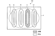
- FIG. FIG. 2 is a plan view schematically showing a plurality of heating coils of the induction heating cooker according to the first embodiment.
- the induction heating cooking appliance 100 has the top plate 4 in which to-be-heated objects, such as a pan, are mounted in upper part.
- the top plate 4 is entirely made of a material that transmits infrared rays, such as heat-resistant tempered glass or crystallized glass.
- the induction heating cooker 100 includes a plurality of heating coils arranged in a line on the same plane.
- the plurality of heating coils are arranged below the top plate 4.
- an induction heating cooker 100 is shown that includes four heating coils, a first heating coil 1 a, a second heating coil 1 b, a third heating coil 1 c, and a fourth heating coil 1 d. Yes.
- the first heating coil 1a to the fourth heating coil 1d are arranged in a row in the lateral direction of the top plate 4, for example.
- the first heating coil 1a to the fourth heating coil 1d are configured by winding a conductive wire made of a metal with an insulating film.
- the conducting wire for example, any metal such as copper or aluminum can be used.
- the first heating coil 1a to the fourth heating coil 1d are each wound with a conducting wire independently.
- the first heating coil 1a to the fourth heating coil 1d are formed, for example, in an elliptical shape in plan view.
- the first heating coil 1a to the fourth heating coil 1d have the same shape and the same size, respectively.
- the same shape and the same size are not limited to the exact same shape and size, but include errors caused by manufacturing errors, etc., and are substantially the same shape and the same size. This is also acceptable.
- the shapes of the first heating coil 1a to the fourth heating coil 1d are not limited to elliptical shapes.
- the shape of the first heating coil 1a to the fourth heating coil 1d may be, for example, a square shape.
- the first heating coil 1a, the second heating coil 1b, the third heating coil 1c, and the fourth heating coil 1d may be collectively referred to as each heating coil.
- An operation unit 40 is provided on the front side of the top plate 4 as an input device for setting input power, a cooking menu, and the like when the object to be heated is heated by the first heating coil 1a to the fourth heating coil 1d.
- the cooking menu includes, for example, a kettle mode, a fried food mode, a convection mode, and the like.
- the convection mode is a cooking menu that causes convection in a liquid food contained in a heated object in cooking such as stew or boiled noodles. Details will be described later.
- a display unit 41 is provided as an informing means for displaying the operation state of each heating coil, the input from the operation unit 40, the operation content, and the like.
- the display unit 41 is divided for each induction heating unit to form the display unit 41a, the display unit 41b, and the display unit 41c.
- the operation unit 40 includes, for example, a mechanical switch such as a push switch and a tact switch, a touch switch that detects an input operation based on a change in the capacitance of the electrode, and the like.
- the display part 41 is comprised by LCD, LED, etc., for example.
- the operation unit 40 and the display unit 41 may be an operation display unit 43 configured integrally with them.
- the operation display unit 43 is configured by, for example, a touch panel in which touch switches are arranged on the upper surface of the LCD.
- LCD is an abbreviation for Liquid Crystal Device.
- LED is an abbreviation for Light Emitting Diode.
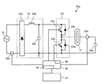
- a drive circuit 50 for supplying high frequency power to the first heating coil 1a to the fourth heating coil 1d is provided inside the induction heating cooker 100.
- a control unit 45 for controlling the operation of the induction heating cooker 100 as a whole including the drive circuit 50 is provided inside the induction heating cooker 100.
- the driving circuit 50 supplies high-frequency power to the first heating coil 1a to the fourth heating coil 1d, a high-frequency magnetic field is generated from the first heating coil 1a to the fourth heating coil 1d.
- the drive circuit 50 is provided for every heating coil, the circuit structure may be the same and may be changed for every heating coil. The detailed configuration of the drive circuit 50 will be described later.
- FIG. 3 is a plan view for explaining the arrangement of a plurality of heating coils of the induction heating cooker according to the first embodiment.
- the elliptical short axis is arranged on the straight line CL. That is, the first heating coil 1a to the fourth heating coil 1d are arranged in a line so that the elliptical long axis LA is orthogonal to the straight line CL. Further, the first heating coil 1a to the fourth heating coil 1d are arranged such that the distance L2 between two adjacent heating coils is shorter than half the length L1 of the short axis of the heating coil.
- FIG. 4 is a block diagram illustrating a configuration of the induction heating cooker according to the first embodiment.
- the drive circuit 50 includes a drive circuit 50a, a drive circuit 50b, a drive circuit 50c, and a drive circuit 50d.
- the first heating coil 1a is driven and controlled by the drive circuit 50a.
- the second heating coil 1b is driven and controlled by the drive circuit 50b.
- the third heating coil 1c is driven and controlled by the drive circuit 50c.
- the fourth heating coil 1d is driven and controlled by the drive circuit 50d.
- a high frequency magnetic field is generated from the first heating coil 1a.
- a high frequency magnetic field is generated from the second heating coil 1b.
- a high frequency magnetic field is generated from the third heating coil 1c.
- a high frequency magnetic field is generated from the fourth heating coil 1d.
- the control unit 45 is configured by dedicated hardware or a CPU that executes a program stored in the memory 48. Moreover, the control part 45 determines the presence or absence of the to-be-heated object mounted on each of the 1st heating coil 1a, the 2nd heating coil 1b, the 3rd heating coil 1c, and the 4th heating coil 1d. Part 46 is provided.
- CPU is an abbreviation for Central Processing Unit. The CPU is also referred to as a central processing unit, a processing unit, or an arithmetic unit.
- control unit 45 When the control unit 45 is dedicated hardware, the control unit 45 corresponds to, for example, a single circuit, a composite circuit, an ASIC, an FPGA, or a combination thereof. Each functional unit realized by the control unit 45 may be realized by individual hardware, or each functional unit may be realized by one piece of hardware.
- ASIC is an abbreviation for Application Specific Integrated Circuit.
- FPGA is an abbreviation for Field-Programmable Gate Array.
- each function executed by the control unit 45 is realized by software, firmware, or a combination of software and firmware.
- Software and firmware are described as programs and stored in the memory 48.
- the CPU implements each function of the control unit 45 by reading and executing the program stored in the memory 48.
- the memory 48 is a non-volatile or volatile semiconductor memory such as RAM, ROM, flash memory, EPROM, or EEPROM.
- a part of the function of the control unit 45 may be realized by dedicated hardware, and a part may be realized by software or firmware.
- RAM is an abbreviation for Random Access Memory.
- ROM is an abbreviation for Read Only Memory.
- EPROM is an abbreviation for Erasable Programmable Read Only Memory.
- EEPROM is an abbreviation for Electrically Erasable Programmable Read-Only Memory.
- FIG. 5 is a diagram illustrating a drive circuit of the induction heating cooker according to the first embodiment.
- the drive circuits 50a to 50d may have the same circuit configuration or may be changed for each heating coil.
- FIG. 5 shows a drive circuit 50a for driving the first heating coil 1a.
- the drive circuit 50a includes a DC power supply circuit 22, an inverter circuit 23, and a resonance capacitor 24a.
- the DC power supply circuit 22 includes a diode bridge 22a, a reactor 22b, and a smoothing capacitor 22c, converts an AC voltage input from the AC power supply 21 into a DC voltage, and outputs the DC voltage to the inverter circuit 23.
- the DC power supply circuit 22 may be shared by each of the drive circuits 50a to 50d.
- IGBTs 23 a and IGBTs 23 b as switching elements are connected in series to the output of the DC power supply circuit 22.
- a diode 23c and a diode 23d are connected in parallel with the IGBT 23a and the IGBT 23b, respectively, as flywheel diodes.
- the inverter circuit 23 is a so-called half-bridge type inverter.
- the IGBT 23 a and the IGBT 23 b are driven on and off by a drive signal output from the control unit 45.
- the control unit 45 turns off the IGBT 23b while turning on the IGBT 23a, turns on the IGBT 23b while turning off the IGBT 23a, and outputs a drive signal that turns on and off alternately.
- the inverter circuit 23 converts the DC power output from the DC power supply circuit 22 into high-frequency AC power of about 20 kHz to 100 kHz, and supplies power to the resonance circuit composed of the first heating coil 1a and the resonance capacitor 24a. Supply.
- the resonance capacitor 24a is connected in series with the first heating coil 1a.
- a resonance circuit composed of the first heating coil 1a and the resonance capacitor 24a has a resonance frequency corresponding to the inductance of the first heating coil 1a and the capacity of the resonance capacitor 24a.
- the inductance of the first heating coil 1a changes according to the characteristics of the metal load when an object to be heated that is a metal load is magnetically coupled, and the resonance frequency of the resonance circuit changes according to the change in the inductance.
- the IGBTs 23a and IGBTs 23b which are switching elements, are composed of, for example, a silicon-based semiconductor, but may be configured using a wide band gap semiconductor such as silicon carbide or a gallium nitride-based material.
- the conduction loss of the switching element can be reduced. Further, even if the drive frequency is set to a high frequency, that is, the switching is performed at a high speed, the heat radiation of the drive circuit 50a is good. Therefore, the heat radiation fins of the drive circuit 50 can be reduced in size. Cost reduction can be realized.
- the drive circuit 50a has input current detection means 25a and coil current detection means 25b.
- the input current detection means 25a is constituted by, for example, a current sensor, detects a current input from the AC power supply 21 to the DC power supply circuit 22, and outputs a voltage signal corresponding to the input current value to the control unit 45.
- the coil current detection means 25b is constituted by, for example, a current sensor, detects a current flowing through the first heating coil 1a, and outputs a voltage signal corresponding to the coil current value to the control unit 45.
- the load determination unit 46 of the control unit 45 performs a load determination process.
- the load determination unit 46 places an object to be heated above each heating coil based on the relationship between the coil current and the input current of each of the first heating coil 1a to the fourth heating coil 1d. It is determined whether it is placed. Specifically, the load determination unit 46 drives the inverter circuit 23 with a specific drive signal for load determination for each of the drive circuits 50a to 50d. The controller 45 detects the input current from the output signal of the input current detection means 25a. At the same time, the control unit 45 detects the coil current from the output signal of the coil current detection means 25b. The load determination unit 46 determines the presence / absence of an object to be heated placed above each heating coil from the detected coil current and input current and a load determination table stored in the memory 48 in advance.
- the load determination part 46 should just be the structure which determines the presence or absence of the to-be-heated object mounted above each heating coil.
- the load determination unit 46 may determine the presence or absence of an object to be heated by an optical method.
- the load determination unit 46 may determine the presence or absence of the object to be heated by irradiating light from the bottom to the top of the top plate 4 and detecting the reflected light from the object to be heated. .
- control unit 45 controls the drive circuit 50a to the drive circuit 50d according to the result of the load determination process, and performs a heating operation for supplying the heating power for induction heating and the high frequency power corresponding to the cooking menu.
- the size of the heated object placed on the top plate 4 is a small diameter, a medium diameter, and a large diameter.
- the size of the object to be heated 5a placed above the two heating coils is referred to as a small diameter.
- the size of the object to be heated 5b placed above the three heating coils among the first heating coil 1a to the fourth heating coil 1d is referred to as a medium diameter.
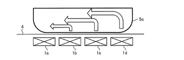
- the size of the object to be heated 5c placed above the four heating coils among the first heating coil 1a to the fourth heating coil 1d is referred to as a large diameter.
- it calls the to-be-heated object 5.
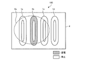
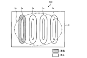
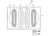
- FIG. 8 and 9 are diagrams showing a plurality of heating coils and an object to be heated of the induction heating cooker according to the first embodiment.
- the first heating coil 1a to the fourth heating coil 1d arranged below the top plate 4 are indicated by solid lines
- the object to be heated 5a placed on the top plate 4 is indicated by a dotted line. Is shown.
- FIG.8 and FIG.9 the longitudinal cross-section of the state by which the to-be-heated material 5a was mounted on the top plate 4 is shown typically.
- FIG.8 and FIG.9 the direction of the convection which arose in the liquid cooking food accommodated in the to-be-heated material 5a is shown by the arrow.
- the control unit 45 supplies power to the second heating coil 1b. And the supply of electric power to the third heating coil 1c are alternately switched over time. That is, when the object to be heated 5a is placed above two adjacent heating coils of the first heating coil 1a to the fourth heating coil 1d, the control unit 45 controls one heating coil of the two heating coils. Electric power is supplied to the heating coil, and the heating coil for supplying electric power is sequentially changed over time.
- control part 45 is the same as the electric energy which is the product of the electric power supplied to the 2nd heating coil 1b, and electricity supply time, and the electric power supplied to the 3rd heating coil 1c, and the electricity supply time.
- the control unit 45 sets the same product of the power supplied to the two adjacent heating coils and the energization time among the first heating coil 1a to the fourth heating coil 1d.
- the same amount of power is not limited to exactly the same value, but includes an error caused by a control error or the like, and the case where the amount of power is substantially the same is allowed. The same applies to the following description.
- (Medium diameter) 10 to 12 are plan views schematically showing energized states of a plurality of heating coils of the induction heating cooker according to the first embodiment.
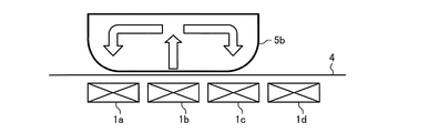
- 13 to 15 are diagrams showing a plurality of heating coils and an object to be heated of the induction heating cooker according to the first embodiment. 10 to 12, the first heating coil 1a to the fourth heating coil 1d disposed below the top plate 4 are indicated by solid lines, and the object to be heated 5b placed on the top plate 4 is indicated by a dotted line.
- Is shown. 13 to 15 schematically show vertical sections in a state where the object to be heated 5b is placed on the top plate 4.
- the control unit 45 performs the following operation. Do.
- the controller 45 sequentially changes the supply of power to the first heating coil 1a, the supply of power to the second heating coil 1b, and the supply of power to the third heating coil 1c with the passage of time. That is, when the object to be heated 5b is placed above the adjacent three heating coils of the first heating coil 1a to the fourth heating coil 1d, the control unit 45 controls one heating coil of the three heating coils. Electric power is supplied to the heating coil, and the heating coil for supplying electric power is sequentially changed over time.
- control part 45 makes the electric energy which is the product of the electric power supplied to the 1st heating coil 1a, the 2nd heating coil 1b, and the 3rd heating coil 1c, and energization time the same, respectively. That is, the control unit 45 sets the same product of the power supplied to the three adjacent heating coils and the energization time among the first heating coil 1a to the fourth heating coil 1d.
- the order in which power is supplied to the three adjacent heating coils is not limited to the order of the first heating coil 1a, the second heating coil 1b, and the third heating coil 1c, but may be any order.
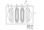
- 16 to 19 are plan views schematically showing energized states of a plurality of heating coils of the induction heating cooker according to the first embodiment.
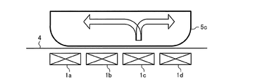
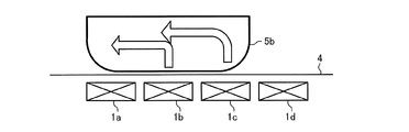
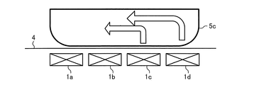
- 20 to 23 are diagrams showing a plurality of heating coils and an object to be heated of the induction heating cooker according to the first embodiment. 16 to 19, the first heating coil 1a to the fourth heating coil 1d disposed below the top plate 4 are indicated by solid lines, and the object to be heated 5c placed on the top plate 4 is indicated by a dotted line.
- Is shown. 20 to 23 schematically show a longitudinal section in a state where the object to be heated 5c is placed on the top plate 4.
- FIG. In FIGS. 20 to 23, the direction of convection generated in the liquid food contained in the article to be heated 5c is indicated by an arrow.
- the controller 45 performs the following operations: The control unit 45 supplies power to the first heating coil 1a, supplies power to the second heating coil 1b, supplies power to the third heating coil 1c, and supplies power to the fourth heating coil 1d.
- the supply is sequentially changed over time. That is, when the object to be heated 5c is placed above four adjacent heating coils among the first heating coil 1a to the fourth heating coil 1d, the control unit 45 controls one heating coil among the four heating coils. Electric power is supplied to the heating coil, and the heating coil for supplying electric power is sequentially changed over time.
- control part 45 makes the electric energy which is the product of the electric power supplied to the 1st heating coil 1a, the 2nd heating coil 1b, the 3rd heating coil 1c, and the 4th heating coil 1d, and energization time, respectively the same. . That is, the control unit 45 makes the product of the power supplied to the first heating coil 1a to the fourth heating coil 1d and the energization time the same.
- FIG. 17 when power is supplied to the second heating coil 1b and the supply of power to the first heating coil 1a, the third heating coil 1c, and the fourth heating coil 1d is stopped, it is shown in FIG. Such convection occurs. That is, the liquid cooked food accommodated in the object to be heated 5c is heated on the upper part of the second heating coil 1b and is directed upward from the lower part of the object to be heated 5c, and then the paper surface on the first heating coil 1a side. Convection flows toward the left side and the right side of the drawing, which is the third heating coil 1c side.
- FIG. 18 when power is supplied to the third heating coil 1c and supply of power to the first heating coil 1a, the second heating coil 1b, and the fourth heating coil 1d is stopped, it is shown in FIG. Such convection occurs. That is, the liquid cooked food accommodated in the object to be heated 5c is heated on the upper part of the third heating coil 1c and moves upward from the lower part of the object to be heated 5c, and then the paper surface on the second heating coil 1b side. Convection flows toward the left side and the right side of the drawing, which is the fourth heating coil 1d side.
- the order of supplying power to the four adjacent heating coils is not limited to the order of the first heating coil 1a, the second heating coil 1b, the third heating coil 1c, and the fourth heating coil 1d, and may be any order. .
- the control unit 45 sets the power supplied to some of the two or more adjacent heating coils to be larger than the power supplied to the other heating coils, and supplies the power over time. You may change the heating coil which enlarges.
- the control unit 45 places the article to be heated 5 above two or more adjacent heating coils of the first heating coil 1a to the fourth heating coil 1d.
- power is supplied to some of the two or more adjacent heating coils, and the heating coil that supplies the power is changed as time passes.
- the convection of the liquid foodstuff accommodated in the to-be-heated material 5 can be accelerated
- the article to be heated 5 since cooking is performed by the heating coil in which the article to be heated 5 is placed above the first heating coil 1a to the fourth heating coil 1d, the article to be heated 5 having a size from a small diameter to a large diameter is used. It is possible to improve the convenience for the user.
- control unit 45 calculates the product of the power supplied to two or more adjacent heating coils and the energization time among the first heating coil 1a to the fourth heating coil 1d, respectively. Make the same. For this reason, the nonuniformity of the heating temperature of the to-be-heated material 5 can be suppressed, and the nonuniformity of the temperature of a cooking item can be suppressed.
- the first heating coil 1a to the fourth heating coil 1d have the same shape and the same size, respectively. For this reason, the area in planar view of each heating coil becomes the same, and the nonuniformity of the heating temperature of the to-be-heated material 5 can be suppressed.
- the first heating coil 1a to the fourth heating coil 1d are arranged such that the distance L2 between two adjacent heating coils is shorter than half the length L1 of the short axis of the heating coil. Yes. For this reason, the temperature fall of the to-be-heated material 5 between two heating coils can be suppressed, and the nonuniformity of heating temperature can be suppressed.
- to-be-heated materials such as a frying pan or an iron plate in which a solid cooking food is mounted
- the heating operation described above may be applied. Since the heated part of the heated object 5 such as a frying pan or an iron plate is changed over time, the solid food placed on the heated object 5 is heated or kept warm while suppressing burning. Is possible.
- control unit 45 operates to make the product of the power supplied to the three or more adjacent heating coils and the energization time the same among the first heating coil 1a to the fourth heating coil 1d.
- the heat radiation amount is larger than that in the central part. For this reason, the temperature of the outer peripheral portion of the article to be heated 5 is likely to be lower than that of the central portion. For this reason, it may replace with said operation
- the control unit 45 When the object to be heated 5 is placed above three or more adjacent heating coils among the first heating coil 1a to the fourth heating coil 1d, the control unit 45 performs the following operation.
- the control part 45 is the one or two arrange
- the control unit 45 when the medium-sized heated object 5b is placed above the first heating coil 1a, the second heating coil 1b, and the third heating coil 1c, the control unit 45 performs the following operation.
- the controller 45 is an electric energy that is the product of the electric power supplied to the first heating coil 1a and the third heating coil 1c and the energization time, and an electric energy that is the product of the electric power supplied to the second heating coil 1b and the energization time. Larger than.
- the control unit 45 performs the operation.
- the controller 45 supplies the amount of power that is the product of the power supplied to the first heating coil 1a and the fourth heating coil 1d and the energization time, the power supplied to the second heating coil 1b and the third heating coil 1c, and the energization time. To be larger than the amount of power that is the product of
- the calorific value of the outer peripheral part of the object to be heated 5 can be made larger than that of the central part, and uneven heating temperature of the object to be heated 5 can be suppressed. Therefore, it is possible to suppress unevenness of the temperature of the cooked food and scorching of the cooked food.
- Embodiment 2 FIG.
- the operation of the induction heating cooker 100 in the second embodiment will be described focusing on the differences from the first embodiment.
- the structure of the induction heating cooking appliance 100 in Embodiment 2 is the same as that of the said Embodiment 1.
- FIG. The same parts as those in the first embodiment are denoted by the same reference numerals, and description thereof is omitted.
- the load determination unit 46 of the control unit 45 determines the load as in the first embodiment. Process.
- the control unit 45 controls the drive circuit 50a to the drive circuit 50d according to the result of the load determination process, and performs a heating operation according to the heating power to be induction-heated and the cooking menu.
- the operation when the convection mode is selected as the cooking menu by the input from the operation unit 40 will be described separately when the size of the object to be heated placed on the top plate 4 is the medium diameter and the large diameter. To do.
- FIG.26 and FIG.27 are plan views schematically showing energized states of a plurality of heating coils of the induction heating cooker according to the second embodiment.
- FIG.26 and FIG.27 is a figure which shows the several heating coil and to-be-heated material of the induction heating cooking appliance which concerns on Embodiment 2.
- FIG. 24 and 25, the first heating coil 1a to the fourth heating coil 1d disposed below the top plate 4 are indicated by solid lines, and the object to be heated 5b placed on the top plate 4 is indicated by a dotted line.
- Is shown. 26 and 27 schematically show a longitudinal section in a state where the object to be heated 5b is placed on the top plate 4.
- the direction of the convection which arose in the liquid cooking goods accommodated in the to-be-heated material 5b is shown by the arrow.
- the control unit 45 performs the following operation. Do.
- the controller 45 alternately switches between power supply to the first heating coil 1a and the third heating coil 1c and power supply to the second heating coil 1b. That is, when the object to be heated 5b is placed above three adjacent heating coils among the first heating coil 1a to the fourth heating coil 1d, the control unit 45 is closer to the center of the three heating coils.
- the supply of electric power to one heating coil arranged in the above and the supply of electric power to two heating coils arranged outside are alternately switched.
- control part 45 is the electric energy which is the product of the sum total of the electric power supplied to the 1st heating coil 1a and the 3rd heating coil 1c, and energization time, and the electric power supplied to the 2nd heating coil 1b, and energization time.
- the power amount that is the product is made the same.
- the power supply to one heating coil arranged closer to the center and the power supply to two heating coils arranged closer to the outside are alternately switched.
- convection occurs in the liquid cooking product such as the broth contained in the article to be heated 5b, and the liquid cooking product can be diffused.
- FIGS. 30 and 31 are plan views schematically showing energization states of a plurality of heating coils of the induction heating cooker according to the second embodiment.
- 30 and 31 are diagrams showing a plurality of heating coils and an object to be heated of the induction heating cooker according to the second embodiment.
- the first heating coil 1a to the fourth heating coil 1d arranged below the top plate 4 are indicated by solid lines
- the object to be heated 5c placed on the top plate 4 is indicated by a dotted line.
- Is shown. 30 and 31 schematically show a longitudinal section in a state where the object to be heated 5c is placed on the top plate 4.
- the direction of convection generated in the liquid food contained in the article to be heated 5c is indicated by an arrow.
- the controller 45 performs the following operations: The controller 45 alternately switches between supplying power to the first heating coil 1a and the fourth heating coil 1d and supplying power to the second heating coil 1b and the third heating coil 1c. That is, when the object to be heated 5c is placed above the four adjacent heating coils, the control unit 45 supplies power to the two heating coils disposed closer to the center among the four heating coils. The power supply to the two heating coils arranged outside is alternately switched.
- control part 45 supplies the electric energy which is the product of the sum total of the electric power supplied to the 1st heating coil 1a and the 4th heating coil 1d, and the energization time, and the 2nd heating coil 1b and the 3rd heating coil 1c.
- the power amount that is the product of the total power and the energization time is made the same.
- FIG. 28 when power is supplied to the first heating coil 1a and the fourth heating coil 1d and the supply of power to the second heating coil 1b and the third heating coil 1c is stopped, it is shown in FIG. Such convection occurs. That is, the liquid cooked food accommodated in the object to be heated 5c is heated on the upper part of the first heating coil 1a and then upwards from the lower part of the object to be heated 5c, and then the paper surface on the second heating coil 1b side. Convection to the right occurs. At the same time, the liquid cooked food housed in the article to be heated 5c is on the third heating coil 1c side after the upper part of the fourth heating coil 1d is heated and directed upward from the lower part of the article to be heated 5c. Convection toward the left side of the page occurs. And the liquid cooking food accommodated in the to-be-heated material 5c produces the downward convection in the center part of the to-be-heated material 5c.
- FIG. 28 when electric power is supplied to the second heating coil 1b and the third heating coil 1c and the supply of electric power to the first heating coil 1a and the fourth heating coil 1d is stopped, it is shown in FIG. Such convection occurs. That is, the liquid cooked food accommodated in the object to be heated 5c is heated on the upper part of the second heating coil 1b and is directed upward from the lower part of the object to be heated 5c, and then the paper surface on the first heating coil 1a side. Convection toward the left side occurs. At the same time, the liquid cooked food accommodated in the object to be heated 5c is on the fourth heating coil 1d side after the upper part of the third heating coil 1c is heated and heads upward from the lower part of the object to be heated 5c. Convection toward the right side of the page occurs.
- the power supply to the two heating coils arranged closer to the center and the power supply to the two heating coils arranged closer to the outside are alternately switched.
- convection occurs in the liquid cooking product such as the broth contained in the article to be heated 5b, and the liquid cooking product can be diffused.
- control part 45 may make the electric power supplied to a part of heating coils larger than the electric power supplied to another heating coil among three or more adjacent heating coils.
- the control unit 45 places the article to be heated 5 above three or more adjacent heating coils among the first heating coil 1a to the fourth heating coil 1d.
- power is supplied to one or two or more heating coils arranged closer to the center and to two or more heating coils arranged closer to the outside.
- the power supply is switched alternately.
- the convection which goes to the center part from the outer peripheral part of the to-be-heated material 5 and the convection which goes to the outer peripheral part from a center part can be produced
- the heating part of the to-be-heated material 5 is changed with progress of time, it becomes possible to warm or keep warm the liquid cooking food accommodated in the to-be-heated material 5 while suppressing burning.
- control unit 45 calculates the product of the power supplied to three or more adjacent heating coils and the energization time among the first heating coil 1a to the fourth heating coil 1d. Make the same. For this reason, the nonuniformity of the heating temperature of the to-be-heated material 5 can be suppressed, and the nonuniformity of the temperature of a cooking item can be suppressed.
- to-be-heated materials such as a frying pan or an iron plate in which a solid cooking food is mounted
- the heating operation described above may be applied. Since the heated part of the heated object 5 such as a frying pan or an iron plate is changed over time, the solid food placed on the heated object 5 is heated or kept warm while suppressing burning. Is possible.
- the control unit 45 may alternately perform the heating operation of the induction heating cooker 100 in the second embodiment and the heating operation of the induction heating cooker 100 in the first embodiment.
- control unit 45 operates to make the product of the power supplied to the three or more adjacent heating coils and the energization time the same among the first heating coil 1a to the fourth heating coil 1d.
- the heat radiation amount is larger than that in the central part. For this reason, the temperature of the outer peripheral portion of the article to be heated 5 is likely to be lower than that of the central portion. For this reason, it may replace with said operation
- the control unit 45 When the object to be heated 5 is placed above three or more adjacent heating coils among the first heating coil 1a to the fourth heating coil 1d, the control unit 45 performs the following operation.
- the control part 45 is the one or two arrange
- control unit 45 when the medium-sized heated object 5b is placed above the first heating coil 1a, the second heating coil 1b, and the third heating coil 1c, the control unit 45 performs the following operation.
- the control unit 45 is the product of the power supplied to the second heating coil 1b and the energization time, which is the product of the sum of the power supplied to the first heating coil 1a and the third heating coil 1c and the energization time. Make it larger than the amount of power.
- control unit 45 performs the operation.
- the control part 45 is the sum of the electric power supplied to the 2nd heating coil 1b and the 3rd heating coil 1c with the electric energy which is the product of the sum total of the electric power supplied to the 1st heating coil 1a and the 4th heating coil 1d, and electricity supply time. And larger than the amount of power that is the product of the energization time.
- the calorific value of the outer peripheral part of the object to be heated 5 can be made larger than that of the central part, and uneven heating temperature of the object to be heated 5 can be suppressed. Therefore, it is possible to suppress unevenness of the temperature of the cooked food and scorching of the cooked food.
- Embodiment 3 the operation of the induction heating cooker 100 in the third embodiment will be described focusing on the differences from the first and second embodiments.
- the structure of the induction heating cooking appliance 100 in Embodiment 3 is the same as that of the said Embodiment 1.
- FIG. The same parts as those in the first embodiment are denoted by the same reference numerals, and description thereof is omitted.
- the load determination unit 46 of the control unit 45 determines the load as in the first embodiment. Process.
- the control unit 45 controls the drive circuit 50a to the drive circuit 50d according to the result of the load determination process, and performs a heating operation according to the heating power to be induction-heated and the cooking menu.
- the operation when the convection mode is selected as the cooking menu by the input from the operation unit 40 will be described separately when the size of the object to be heated placed on the top plate 4 is the medium diameter and the large diameter. To do.
- FIG.34 and FIG.35 is a figure which shows the some heating coil and to-be-heated material of the induction heating cooking appliance which concerns on Embodiment 3.
- FIG. 32 and 33 the first heating coil 1a to the fourth heating coil 1d arranged below the top plate 4 are shown by solid lines, and the object to be heated 5b placed on the top plate 4 is shown by a dotted line. Is shown.
- the longitudinal cross-section of the state by which the to-be-heated material 5b was mounted on the top plate 4 is shown typically.
- the direction of the convection which arose in the liquid cooking goods accommodated in the to-be-heated material 5b is shown by the arrow.
- the control unit 45 when the heated object 5b is placed above the first heating coil 1a, the second heating coil 1b, and the third heating coil 1c, the control unit 45 performs the following operation. Do. The control unit 45 alternately supplies power to the set including the first heating coil 1a and the second heating coil 1b and supplies power to the set including the second heating coil 1b and the third heating coil 1c. Switch. That is, when the object to be heated 5b is placed above the three adjacent heating coils among the first heating coil 1a to the fourth heating coil 1d, the control unit 45 selects the one of the three adjacent heating coils. Power is supplied to a pair of two heating coils adjacent to each other, and the pair of two heating coils is changed over time.
- control part 45 supplies the electric energy which is the product of the sum total of the electric power supplied to the 1st heating coil 1a and the 2nd heating coil 1b, and the energization time, and the 2nd heating coil 1b and the 3rd heating coil 1c.
- the power amount that is the product of the total power and the energization time is made the same.
- the object to be heated 5b Convection occurs in the liquid food such as the broth contained in the liquid, and the liquid food can be diffused.
- FIG. 38 and FIG.39 are plan views schematically showing energization states of a plurality of heating coils of the induction heating cooker according to the third embodiment.
- FIG.38 and FIG.39 is a figure which shows the several heating coil and to-be-heated material of the induction heating cooking appliance which concerns on Embodiment 3.
- FIG. 36 and 37, the first heating coil 1a to the fourth heating coil 1d arranged below the top plate 4 are indicated by solid lines, and the object to be heated 5c placed on the top plate 4 is indicated by a dotted line.
- Is shown. 38 and 39 schematically show a longitudinal section in a state where the object to be heated 5c is placed on the top plate 4.
- the direction of the convection which arose in the liquid cooking food accommodated in the to-be-heated material 5c is shown by the arrow.
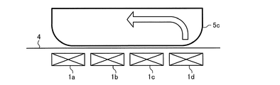
- the controller 45 performs the following operations: The control unit 45 alternately supplies power to the set including the first heating coil 1a and the second heating coil 1b and supplies power to the set including the third heating coil 1c and the fourth heating coil 1d. Switch. That is, when the article to be heated 5c is placed above the four adjacent heating coils, the control unit 45 is a part of the four adjacent heating coils, and includes two adjacent heating coils. Electric power is supplied to the set, and the set of two heating coils is changed over time.
- control part 45 supplies the electric energy which is the product of the sum total of the electric power supplied to the 1st heating coil 1a and the 2nd heating coil 1b, and energization time, and the 3rd heating coil 1c and the 4th heating coil 1d.
- the power amount that is the product of the total power and the energization time is made the same.
- FIG. 37 when power is supplied to the set of the third heating coil 1c and the fourth heating coil 1d and the supply of power to the first heating coil 1a and the second heating coil 1b is stopped, FIG. Convection occurs as shown in That is, the liquid cooked food accommodated in the object to be heated 5c is heated at the upper part of the third heating coil 1c and the fourth heating coil 1d, and then moved upward from the lower part of the object to be heated 5c. Convection flows toward the left side of the drawing, which is the heating coil 1b side.
- the object to be heated 5c Convection occurs in the liquid food such as the broth contained in the liquid, and the liquid food can be diffused.
- control part 45 may make the electric power supplied to a part of heating coils larger than the electric power supplied to another heating coil among three or more adjacent heating coils.
- the control unit 45 places the article 5 to be heated above three or more adjacent heating coils among the first heating coil 1a to the fourth heating coil 1d.
- power is supplied to a set of two adjacent heating coils that are part of three or more adjacent heating coils, and the two heating coil sets are changed over time.
- it is possible to generate convection from one end portion to the other end portion in the arrangement of the plurality of heating coils, and to switch the direction alternately, to diffuse boiled juice in cooking such as boiled food, and eliminate uneven taste.
- the effect of improving the penetration of taste since the heating part of the to-be-heated material 5 is changed with progress of time, it becomes possible to warm or keep warm the liquid cooking food accommodated in the to-be-heated material 5 while suppressing burning.
- control unit 45 sets the same product of the power supplied to the two adjacent heating coils and the energization time among the first heating coil 1a to the fourth heating coil 1d. To do. For this reason, the nonuniformity of the heating temperature of the to-be-heated material 5 can be suppressed, and the nonuniformity of the temperature of a cooking item can be suppressed.
- to-be-heated materials such as a frying pan or an iron plate in which a solid cooking food is mounted
- the heating operation described above may be applied. Since the heated part of the heated object 5 such as a frying pan or an iron plate is changed over time, the solid food placed on the heated object 5 is heated or kept warm while suppressing burning. Is possible.
- the control unit 45 may sequentially perform the heating operation of the induction heating cooker 100 in the first to third embodiments.
- 40 to 42 are plan views schematically showing energized states of a plurality of heating coils of the induction heating cooker according to the third embodiment.
- 43 to 45 are diagrams showing a plurality of heating coils and an object to be heated of the induction heating cooker according to the third embodiment.
- 40 to 42, the first heating coil 1a to the fourth heating coil 1d arranged below the top plate 4 are indicated by solid lines, and the object to be heated 5c placed on the top plate 4 is indicated by a dotted line.
- Is shown. 43 to 45 schematically show vertical sections in a state where the object to be heated 5c is placed on the top plate 4.
- FIG. In FIGS. 43 to 45 the direction of convection generated in the liquid cooked food accommodated in the article to be heated 5c is indicated by an arrow.
- the controller 45 performs the following operations: The control unit 45 supplies power to the set of the first heating coil 1a and the second heating coil 1b, supplies power to the set of the second heating coil 1b and the third heating coil 1c, and the third heating coil 1c. And the supply of electric power to the set of the fourth heating coil 1d is sequentially changed. That is, when the article to be heated 5c is placed above the four adjacent heating coils, the control unit 45 is a part of the four adjacent heating coils, and includes two adjacent heating coils. Electric power is supplied to the set, and the set of two heating coils is changed over time.
- control part 45 supplies the electric energy which is the product of the sum total of the electric power supplied to the 1st heating coil 1a and the 2nd heating coil 1b, and the energization time, and the 2nd heating coil 1b and the 3rd heating coil 1c.
- the amount of power, which is the product of the total power and the energization time, and the amount of power, which is the product of the total amount of power supplied to the third heating coil 1c and the fourth heating coil 1d, and the energization time are made the same.
- FIG. 41 when power is supplied to the set of the second heating coil 1b and the third heating coil 1c and the supply of power to the first heating coil 1a and the fourth heating coil 1d is stopped, FIG. Convection occurs as shown in That is, the liquid cooked food accommodated in the object to be heated 5c is heated on the upper part of the second heating coil 1b and is directed upward from the lower part of the object to be heated 5c, and then the paper surface on the first heating coil 1a side. Convection toward the left side occurs. At the same time, the liquid cooked food accommodated in the object to be heated 5c is on the fourth heating coil 1d side after the upper part of the third heating coil 1c is heated and heads upward from the lower part of the object to be heated 5c. Convection toward the right side of the page occurs.
- FIG. 42 when power is supplied to the set of the third heating coil 1c and the fourth heating coil 1d and the supply of power to the first heating coil 1a and the second heating coil 1b is stopped, FIG. Convection occurs as shown in That is, the liquid cooked food accommodated in the object to be heated 5c is heated at the upper part of the third heating coil 1c and the fourth heating coil 1d, and then moved upward from the lower part of the object to be heated 5c. Convection flows toward the left side of the drawing, which is the heating coil 1b side.
- 46 and 47 are plan views schematically showing energized states of a plurality of heating coils of the induction heating cooker according to the third embodiment.
- 48 and 49 are diagrams showing a plurality of heating coils and an object to be heated of the induction heating cooker according to the third embodiment.
- 46 and 47, the first heating coil 1a to the fourth heating coil 1d arranged below the top plate 4 are shown by solid lines, and the object to be heated 5c placed on the top plate 4 is shown by a dotted line.
- Is shown. 48 and 49 schematically show a longitudinal section in a state where the object to be heated 5c is placed on the top plate 4.
- FIG. In FIGS. 48 and 49, the direction of convection generated in the liquid food contained in the article to be heated 5c is indicated by an arrow.
- the control unit 45 performs the following operations: The control unit 45 supplies power to a set including the first heating coil 1a, the second heating coil 1b, and the third heating coil 1c, and from the second heating coil 1b, the third heating coil 1c, and the fourth heating coil 1d.
- the power supply to the set is sequentially changed. That is, when the article to be heated 5c is placed above the four adjacent heating coils, the control unit 45 is a part of the four adjacent heating coils, and includes the three adjacent heating coils. Electric power is supplied to the set, and the set of three heating coils is changed over time.
- control unit 45 includes the amount of power that is the product of the total power supplied to the first heating coil 1a, the second heating coil 1b, and the third heating coil 1c and the energization time, the second heating coil 1b, and the third heating coil 1b.
- the amount of power, which is the product of the total power supplied to the heating coil 1c and the fourth heating coil 1d, and the energization time is made the same.
- FIG. 47 when power is supplied to the set of the second heating coil 1b, the third heating coil 1c, and the fourth heating coil 1d and the supply of power to the first heating coil 1a is stopped, FIG. Convection occurs as shown in That is, the upper portion of the second heating coil 1b, the third heating coil 1c, and the fourth heating coil 1d of the liquid cooked food stored in the heated object 5c is heated, and the upper part is moved upward from the lower part of the heated object 5c. After heading, convection flows toward the left side of the page, which is the first heating coil 1a side.
- the object to be heated 5c Convection occurs in the liquid food such as the broth contained in the liquid, and the liquid food can be diffused.
- the convection of the liquid food housed in the article to be heated 5 can be increased as compared with the operation of supplying power to the set of two heating coils.
- the control unit 45 operates to make the product of the power supplied to three or more adjacent heating coils and the energization time of the first heating coil 1a to the fourth heating coil 1d the same. explained.
- the heat radiation amount is larger than that in the central part. For this reason, the temperature of the outer peripheral portion of the article to be heated 5 is likely to be lower than that of the central portion. For this reason, it may replace with said operation
- the control unit 45 When the object to be heated 5 is placed above three or more adjacent heating coils among the first heating coil 1a to the fourth heating coil 1d, the control unit 45 performs the following operation.
- the control part 45 is the one or two arrange
- control unit 45 when the medium-sized heated object 5b is placed above the first heating coil 1a, the second heating coil 1b, and the third heating coil 1c, the control unit 45 performs the following operation.
- the control unit 45 is the product of the power supplied to the second heating coil 1b and the energization time, which is the product of the sum of the power supplied to the first heating coil 1a and the third heating coil 1c and the energization time. Make it larger than the amount of power.
- control unit 45 performs the operation.
- the control part 45 is the sum of the electric power supplied to the 2nd heating coil 1b and the 3rd heating coil 1c with the electric energy which is the product of the sum total of the electric power supplied to the 1st heating coil 1a and the 4th heating coil 1d, and electricity supply time. And larger than the amount of power that is the product of the energization time.
- the calorific value of the outer peripheral part of the object to be heated 5 can be made larger than that of the central part, and uneven heating temperature of the object to be heated 5 can be suppressed. Therefore, it is possible to suppress unevenness of the temperature of the cooked food and scorching of the cooked food.
- Embodiment 4 FIG.
- the operation of the induction heating cooker 100 according to the fourth embodiment will be described focusing on the differences from the first to third embodiments.
- the structure of the induction heating cooking appliance 100 in Embodiment 4 is the same as that of the said Embodiment 1.
- FIG. The same parts as those in the first embodiment are denoted by the same reference numerals, and description thereof is omitted.
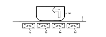
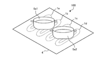
- FIG. 50 is a perspective view showing an induction heating cooker and an object to be heated according to the fourth embodiment.
- the illustration of the configuration below the top plate 4 is omitted.
- the control unit 45 When placed on the upper side of the four heating coils 1d, the control unit 45 performs the following operation.
- the load determination unit 46 of the control unit 45 When an instruction to start heating is given to the operation unit 40, the load determination unit 46 of the control unit 45 performs a load determination process as in the first embodiment.
- the control unit 45 controls the drive circuit 50a to the drive circuit 50d according to the result of the load determination process, and performs a heating operation according to the heating power to be induction-heated and the cooking menu.
- the control unit 45 applies the liquid cooking item accommodated in the object to be heated 5a1.
- the heating operation for generating convection and the heating operation for generating convection in the liquid food contained in the article to be heated 5a2 are simultaneously performed.
- the control unit 45 alternately switches the supply of power to the first heating coil 1a and the supply of power to the second heating coil 1b as time passes.
- the controller 45 alternately switches the supply of power to the third heating coil 1c and the supply of power to the fourth heating coil 1d as time passes.
- the object to be heated 5a is placed above the set of two adjacent heating coils, and two sets of two adjacent heating coils are adjacent to each other. When they match, the power supply to the two adjacent heating coils is alternately switched for each of the two sets.
- the two objects to be heated 5a1 and 5a1 can be heated in the convection mode at the same time, and the convenience for the user can be improved.
- the control part 45 of the induction heating cooking appliance 100 in this Embodiment 4 performs the following operation
- the control part 45 makes the time which supplies electric power simultaneously to the 1st heating coil 1a and the 4th heating coil 1d shorter than the time which supplies electric power to the 2nd heating coil 1b and the 3rd heating coil 1c simultaneously. That is, the control unit 45 simultaneously supplies power to the two heating coils arranged closer to the center among the plurality of heating coils, and simultaneously supplies power to the two heating coils arranged closer to the center. Shorter than. A specific example will be described with reference to FIGS.
- FIG. 51 is a diagram illustrating the heating operation of the induction heating cooker according to the fourth embodiment.
- the state where power is supplied to the heating coil is shown as ON, and the state where the supply of power is stopped is shown as OFF.
- the control unit 45 sets the same switching cycle T1 for the power supplied to each heating coil.
- the control part 45 turns ON the 1st heating coil 1a and the 3rd heating coil 1c, and turns OFF the 2nd heating coil 1b and the 4th heating coil 1d in time T1a.
- the first heating coil 1a and the third heating coil 1c are turned off, and the second heating coil 1b and the fourth heating coil 1d are turned on.
- the time T1a and the time T1b are the same time.
- the time for simultaneously supplying power to the first heating coil 1a and the fourth heating coil 1d arranged outside becomes zero.
- the time for simultaneously supplying power to the second heating coil 1b and the third heating coil 1c arranged closer to the center becomes zero. Therefore, the temperature rise of the 2nd heating coil 1b arrange
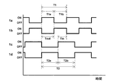
- FIG. 52 is a diagram for explaining the heating operation of the induction heating cooker according to the fourth embodiment.
- the state in which power is supplied to the heating coil is indicated as ON, and the state in which power supply is stopped is indicated as OFF.
- the control unit 45 sets the switching cycle of the power supplied to the first heating coil 1a and the second heating coil 1b to T1.
- the controller 45 turns on the first heating coil 1a and turns off the second heating coil 1b at time T1a. Further, at time T1b, the first heating coil 1a is turned off and the second heating coil 1b is turned on.
- the time T1a and the time T1b are the same time.
- control part 45 sets the switching period of the electric power supplied to the 3rd heating coil 1c and the 4th heating coil 1d to T2 longer than T1.
- the controller 45 turns off the third heating coil 1c and turns on the fourth heating coil 1d at time T2a.
- time T2b the third heating coil 1c is turned on and the fourth heating coil 1d is turned off. Note that time T2a and time T2b are the same time.
- the time Tout for simultaneously supplying power to the first heating coil 1a and the fourth heating coil 1d arranged on the outer side becomes the second heating coil 1b and the third heating coil 1c arranged on the central side. It becomes shorter than the time Tin for simultaneously supplying power to the battery. Therefore, the temperature rise of the 2nd heating coil 1b arrange
- the case where the two heated objects 5a1 and 5a2 are placed above the four heating coils of the first heating coil 1a to the fourth heating coil 1d has been described.
- the number of coils and the number of objects to be heated 5a are not limited to this.
- six heating coils may be arranged in a row, and three objects to be heated 5a may be placed and heated in convection mode by two heating coils, respectively.
- Embodiment 5 FIG.
- the operation of the induction heating cooker 100 in the fifth embodiment will be described focusing on the differences from the first to fourth embodiments.
- the structure of the induction heating cooking appliance 100 in Embodiment 5 is the same as that of the said Embodiment 1.
- FIG. The same parts as those in the first embodiment are denoted by the same reference numerals, and description thereof is omitted.
- the control unit 45 of the induction heating cooker 100 performs the following operation in addition to the same operation as that of any of the first to fourth embodiments.
- the control unit 45 When supplying power to two adjacent heating coils of the first heating coil 1a to the fourth heating coil 1d, the control unit 45 reverses the current flowing in the portion where the two adjacent heating coils face each other. To.
- FIG. 53 is a perspective view schematically showing energized states of a plurality of heating coils of the induction heating cooker according to the fifth embodiment.
- the first heating coil 1a to the fourth heating coil 1d arranged below the top plate 4 are indicated by solid lines, and the heated object 5a1 and the heated object 5a2 placed on the top plate 4 are shown. Is indicated by a dotted line.
- the direction of is indicated by an arrow.
- the control unit 45 when supplying power to the second heating coil 1b and the third heating coil 1c, the control unit 45 supplies the current flowing through the portion where the second heating coil 1b and the third heating coil 1c face each other.
- the drive circuit 50b and the inverter circuit 23 of the drive circuit 50c are driven so as to be in the same direction.
- Embodiment 6 FIG.
- the configuration and operation of the induction heating cooker 100 according to the sixth embodiment will be described focusing on differences from the first to fifth embodiments.
- symbol is attached
- FIG. 54 is a block diagram showing the configuration of the induction heating cooker according to the sixth embodiment.
- the first heating coil 1a and the second heating coil 1b are driven and controlled by the drive circuit 50e.
- the third heating coil 1c and the fourth heating coil 1d are driven and controlled by the drive circuit 50f.
- a high frequency current from the drive circuit 50e to the first heating coil 1a a high frequency magnetic field is generated from the first heating coil 1a.
- a high frequency magnetic field is generated from the second heating coil 1b.
- a high frequency magnetic field is generated from the third heating coil 1c.
- a high frequency magnetic field is generated from the fourth heating coil 1d.
- FIG. 55 is a diagram showing a drive circuit of the induction heating cooker according to the sixth embodiment.
- FIG. 55 illustrates a drive circuit 50e that drives the first heating coil 1a and the second heating coil 1b.
- the drive circuit 50e includes a DC power supply circuit 22, an inverter circuit 23, a resonance capacitor 24a, a resonance capacitor 24b, a resonance capacitor 24c, and a switch 26.
- the configurations of the DC power supply circuit 22 and the inverter circuit 23 are the same as those in the first embodiment.
- a resonance capacitor 24a is connected in series to the first heating coil 1a.
- a resonance capacitor 24b is connected in series to the second heating coil 1b.
- a resonance capacitor 24 c is connected in parallel to the resonance capacitor 24 b via a switch 26.
- the first resonance circuit composed of the first heating coil 1a and the resonance capacitor 24a and the second resonance circuit composed of the second heating coil 1b, the resonance capacitor 24b and the resonance capacitor 24c are connected in parallel.
- the first resonance circuit has a resonance frequency corresponding to the inductance of the first heating coil 1a and the capacitance of the resonance capacitor 24a.
- the second resonance circuit has a resonance frequency corresponding to the inductance of the second heating coil 1b and the capacitances of the resonance capacitor 24b and the resonance capacitor 24c.
- the switch 26 is switched on and off by the control unit 45. When the switch 26 is in the on state, the resonance capacitor 24c is connected in parallel to the resonance capacitor 24b.
- the switch 26 is configured by, for example, a power semiconductor or a relay.
- the resonance frequency of the second resonance circuit is the first resonance frequency f1 corresponding to the combined capacitance of the resonance capacitor 24b and the resonance capacitor 24c and the inductance of the second heating coil 1b.
- the resonance frequency of the second resonance circuit is the second resonance frequency f2 corresponding to the capacitance of only the resonance capacitor 24b and the inductance of the second heating coil 1b. That is, the second resonance frequency f2 when the switch 26 is off is higher than the first resonance frequency f1 when the switch 26 is on.
- the first heating coil 1a and the second heating coil 1b are configured to have substantially the same inductance.
- the capacitance of the resonance capacitor 24a and the combined capacitance of the resonance capacitor 24b and the resonance capacitor 24b are configured to have substantially the same value. That is, the resonance frequency of the first resonance circuit is substantially the same value as the first resonance frequency f1 when the switch 26 is in the ON state in the second resonance circuit.
- the coil current detection means 25b detects the current flowing through the first heating coil 1a and outputs a voltage signal corresponding to the coil current value to the control unit 45.
- the coil current detection means 25c detects the current flowing through the second heating coil 1b and outputs a voltage signal corresponding to the coil current value to the control unit 45.
- the drive circuit 50e for driving the first heating coil 1a and the second heating coil 1b has been described.
- the drive circuit 50f for driving the third heating coil 1c and the fourth heating coil 1d has the same configuration. Can be applied.
- FIG. 55 demonstrated the structure which drives the two 1st heating coils 1a and the 2nd heating coils 1b by the one drive circuit 50e
- the number of heating coils is not limited to this.
- One drive circuit 50e is configured to supply high frequency power to two or more heating coils, and includes a plurality of resonance capacitors that form a resonance circuit with each of the two or more heating coils. At least one of the capacitors may have a variable capacity.
- the control unit 45 of the induction heating cooker 100 changes the capacity of the resonance capacitor in the second resonance circuit and the drive frequency of the inverter circuit 23, thereby changing the two first heating coils 1a and the second. An operation of changing the magnitude of the electric power supplied to the heating coil 1b is performed.
- control unit 45 when the small-diameter heated object 5a1 is placed above the first heating coil 1a and the second heating coil 1b will be described. .
- the load determination unit 46 of the control unit 45 performs a load determination process when an instruction to start heating is given to the operation unit 40.
- the load determination unit 46 detects the input current from the output signal of the input current detection means 25a.
- the control unit 45 detects the coil current from the output signals of the coil current detection means 25b and the coil current detection means 25c.
- the load determination unit 46 determines the presence / absence of an object to be heated placed above each heating coil from the detected coil current and input current and a load determination table stored in the memory 48 in advance.
- the control unit 45 controls the drive circuit 50e and the drive circuit 50f according to the result of the load determination process, and performs a heating operation according to the heating power to be induction-heated and the cooking menu.
- the control unit 45 When a cooking menu for cooking the object to be heated 5a1 in the convection mode is selected by an input from the operation unit 40, the control unit 45 performs heating to generate convection in the liquid food accommodated in the object to be heated 5a1. Perform the action. Specifically, when the cooking menu in the convection mode is selected, the control unit 45 turns off the switch 26 of the drive circuit 50e. As a result, the resonance frequency of the second resonance circuit is changed from the first resonance frequency f1 to the second resonance frequency f2. The control part 45 changes the magnitude
- FIG. 56 is a conceptual diagram showing the relationship between the drive frequency of the induction heating cooker according to Embodiment 6 and the power supplied to the heating coil.
- the first resonance circuit and the second resonance circuit when the switch 26 is in the ON state have a characteristic in which the first resonance frequency f ⁇ b> 1 is a peak as indicated by the power characteristic 60.
- the second resonance circuit when the switch 26 is in the OFF state has a characteristic that peaks at the second resonance frequency f ⁇ b> 2 as indicated by the power characteristic 61.
- a frequency range in which the power in the power characteristic 60 is greater than or equal to the first resonance frequency f ⁇ b> 1 and larger than the power characteristic 61 is preset as the operation region A. Further, in the control unit 45, a frequency range equal to or higher than the second resonance frequency f2 is preset as the operation region B.
- the upper limit frequency of the operation region B is set to an upper limit value of the operation range of the drive circuit 50e, for example, 100 kHz.
- the power supplied to the second resonance circuit when the first resonance circuit and the switch 26 are on is the second resonance when the switch 26 is off. It is greater than the power supplied to the circuit. Further, when the drive circuit 50e is driven at a drive frequency within the range of the operation region B, the power supplied to the second resonance circuit when the first resonance circuit and the switch 26 are on is the same as that when the switch 26 is off. 2 Less than the power supplied to the resonant circuit.
- the control unit 45 sets the drive frequency of the inverter circuit 23 of the drive circuit 50e to the drive frequency within the range of the operation region A and the operation region B.
- the driving frequency is alternately switched to a driving frequency within the range.
- the control unit 45 turns on the switch 26 and turns on the second resonance circuit. Is changed to the first resonance frequency f1. Thereby, the same electric power is supplied to the 1st heating coil 1a and the 2nd heating coil 1b.
- the configuration and operation of the induction heating cooker 100 according to the sixth embodiment may be combined with any of the first to fifth embodiments.
- the first heating coil 1a to the fourth heating coil 1d are driven by one drive circuit 50, and the capacitance of the resonance capacitor that forms a resonance circuit with each of the heating coils is variable.
- the control part 45 can change arbitrarily the magnitude
- FIG. 57 is a plan view schematically showing a plurality of heating coils of the induction heating cooker according to the first modification.
- the first heating coil 1a to the fourth heating coil 1d may be arranged in a line in the vertical direction of the top plate 4, for example. Also in this configuration, the same operation as in the first to sixth embodiments can be performed, and the same effect can be obtained.
- the induction heating cooker 100 has been described as including the first heating coil 1a to the fourth heating coil 1d, but the present invention is not limited to this.
- a plurality of heating ports may be provided, and one of them may have a plurality of heating coils arranged in a line.
- FIG. 58 is an exploded perspective view showing an induction heating cooker according to the second modification.
- an induction heating cooker 101 including a first heating port 1, a second heating port 2, and a third heating port 3 the first heating coils 1a to 1 are provided below the first heating port 1.
- the fourth heating coil 1d may be arranged in a row.
- positioned under the 3rd heating port 3 are comprised by the circular coil, for example. Also in this configuration, the same operation as in the first to sixth embodiments can be applied to the first heating port 1.
Landscapes
- Physics & Mathematics (AREA)
- Electromagnetism (AREA)
- Engineering & Computer Science (AREA)
- Power Engineering (AREA)
- Induction Heating Cooking Devices (AREA)
Priority Applications (5)
| Application Number | Priority Date | Filing Date | Title |
|---|---|---|---|
| PCT/JP2018/010610 WO2019176110A1 (ja) | 2018-03-16 | 2018-03-16 | 誘導加熱調理器 |
| US16/970,817 US11659632B2 (en) | 2018-03-16 | 2018-03-16 | Induction cooker with plurality of heating coils |
| CN201880091106.3A CN111837454B (zh) | 2018-03-16 | 2018-03-16 | 感应加热烹调器 |
| JP2020506098A JP6991309B2 (ja) | 2018-03-16 | 2018-03-16 | 誘導加熱調理器 |
| EP18909385.9A EP3768043A4 (en) | 2018-03-16 | 2018-03-16 | INDUCTION HEATING COOKER |
Applications Claiming Priority (1)
| Application Number | Priority Date | Filing Date | Title |
|---|---|---|---|
| PCT/JP2018/010610 WO2019176110A1 (ja) | 2018-03-16 | 2018-03-16 | 誘導加熱調理器 |
Publications (1)
| Publication Number | Publication Date |
|---|---|
| WO2019176110A1 true WO2019176110A1 (ja) | 2019-09-19 |
Family
ID=67907067
Family Applications (1)
| Application Number | Title | Priority Date | Filing Date |
|---|---|---|---|
| PCT/JP2018/010610 WO2019176110A1 (ja) | 2018-03-16 | 2018-03-16 | 誘導加熱調理器 |
Country Status (5)
| Country | Link |
|---|---|
| US (1) | US11659632B2 (zh) |
| EP (1) | EP3768043A4 (zh) |
| JP (1) | JP6991309B2 (zh) |
| CN (1) | CN111837454B (zh) |
| WO (1) | WO2019176110A1 (zh) |
Families Citing this family (1)
| Publication number | Priority date | Publication date | Assignee | Title |
|---|---|---|---|---|
| US11910509B2 (en) * | 2021-03-02 | 2024-02-20 | Whirlpool Corporation | Method for improving accuracy in load curves acquisition on an induction cooktop |
Citations (7)
| Publication number | Priority date | Publication date | Assignee | Title |
|---|---|---|---|---|
| JP2009158225A (ja) * | 2007-12-26 | 2009-07-16 | Mitsubishi Electric Corp | 誘導加熱調理器 |
| JP2012079581A (ja) * | 2010-10-04 | 2012-04-19 | Mitsubishi Electric Corp | 誘導加熱調理器 |
| JP2013201141A (ja) * | 2013-06-24 | 2013-10-03 | Panasonic Corp | 誘導加熱調理器 |
| JP2013218942A (ja) * | 2012-04-11 | 2013-10-24 | Mitsubishi Electric Corp | 誘導加熱装置 |
| JP2014017273A (ja) * | 2013-10-29 | 2014-01-30 | Mitsubishi Electric Corp | 誘導加熱調理器 |
| JP2016207255A (ja) | 2015-04-15 | 2016-12-08 | パナソニックIpマネジメント株式会社 | 加熱調理器 |
| JP2017135119A (ja) * | 2017-03-28 | 2017-08-03 | 三菱電機株式会社 | 誘導加熱調理器 |
Family Cites Families (17)
| Publication number | Priority date | Publication date | Assignee | Title |
|---|---|---|---|---|
| US3710062A (en) * | 1971-04-06 | 1973-01-09 | Environment One Corp | Metal base cookware induction heating apparatus having improved power supply and gating control circuit using infra-red temperature sensor and improved induction heating coil arrangement |
| US3786222A (en) * | 1972-04-19 | 1974-01-15 | Gen Electric | Metallic foil induction cooking |
| JP2978069B2 (ja) * | 1994-09-06 | 1999-11-15 | 島田理化工業株式会社 | 電磁調理器 |
| DE19945297A1 (de) * | 1999-09-22 | 2001-03-29 | Diehl Ako Stiftung Gmbh & Co | Topferkennung |
| JP4915278B2 (ja) * | 2007-05-15 | 2012-04-11 | 三菱電機株式会社 | 誘導加熱調理器 |
| EP2373120B1 (en) * | 2008-12-26 | 2015-08-12 | Panasonic Corporation | Dielectric heat cooking device |
| EP2252130B1 (en) * | 2009-02-06 | 2012-08-22 | Panasonic Corporation | Electromagnetic cooking device |
| ES2547559T3 (es) * | 2009-03-06 | 2015-10-07 | Mitsubishi Electric Corporation | Sistema de cocción por calentamiento por inducción |
| ES2640965T3 (es) * | 2010-09-03 | 2017-11-07 | Mitsubishi Electric Corporation | Aparato de cocción por inducción |
| KR101835714B1 (ko) * | 2011-04-01 | 2018-03-08 | 삼성전자주식회사 | 유도가열조리기 및 그 제어방법 |
| JP2013109889A (ja) | 2011-11-18 | 2013-06-06 | Panasonic Corp | 誘導加熱装置 |
| US10098188B2 (en) * | 2013-04-25 | 2018-10-09 | Panasonic Intellectual Property Management Co., Ltd. | Induction heating cooker |
| EP3024300B1 (en) | 2013-09-05 | 2017-08-30 | Electrolux Appliances Aktiebolag | An induction cooking hob including a cooking area with three or more induction coils and a method for controlling a cooking area |
| CN204377176U (zh) * | 2014-10-24 | 2015-06-03 | 三菱电机株式会社 | 感应加热烹调器 |
| WO2016181653A1 (ja) * | 2015-05-14 | 2016-11-17 | パナソニックIpマネジメント株式会社 | 誘導加熱調理器 |
| JP6960568B2 (ja) | 2015-11-13 | 2021-11-05 | パナソニックIpマネジメント株式会社 | 誘導加熱調理器 |
| EP3291642A1 (en) * | 2016-09-02 | 2018-03-07 | Electrolux Appliances Aktiebolag | Induction cooking hob and method for controlling a cooking zone |
-
2018
- 2018-03-16 JP JP2020506098A patent/JP6991309B2/ja active Active
- 2018-03-16 CN CN201880091106.3A patent/CN111837454B/zh active Active
- 2018-03-16 EP EP18909385.9A patent/EP3768043A4/en active Pending
- 2018-03-16 US US16/970,817 patent/US11659632B2/en active Active
- 2018-03-16 WO PCT/JP2018/010610 patent/WO2019176110A1/ja active Application Filing
Patent Citations (7)
| Publication number | Priority date | Publication date | Assignee | Title |
|---|---|---|---|---|
| JP2009158225A (ja) * | 2007-12-26 | 2009-07-16 | Mitsubishi Electric Corp | 誘導加熱調理器 |
| JP2012079581A (ja) * | 2010-10-04 | 2012-04-19 | Mitsubishi Electric Corp | 誘導加熱調理器 |
| JP2013218942A (ja) * | 2012-04-11 | 2013-10-24 | Mitsubishi Electric Corp | 誘導加熱装置 |
| JP2013201141A (ja) * | 2013-06-24 | 2013-10-03 | Panasonic Corp | 誘導加熱調理器 |
| JP2014017273A (ja) * | 2013-10-29 | 2014-01-30 | Mitsubishi Electric Corp | 誘導加熱調理器 |
| JP2016207255A (ja) | 2015-04-15 | 2016-12-08 | パナソニックIpマネジメント株式会社 | 加熱調理器 |
| JP2017135119A (ja) * | 2017-03-28 | 2017-08-03 | 三菱電機株式会社 | 誘導加熱調理器 |
Non-Patent Citations (1)
| Title |
|---|
| See also references of EP3768043A4 |
Also Published As
| Publication number | Publication date |
|---|---|
| US11659632B2 (en) | 2023-05-23 |
| CN111837454B (zh) | 2022-08-09 |
| JP6991309B2 (ja) | 2022-01-12 |
| US20210307124A1 (en) | 2021-09-30 |
| EP3768043A4 (en) | 2021-03-17 |
| CN111837454A (zh) | 2020-10-27 |
| JPWO2019176110A1 (ja) | 2020-12-17 |
| EP3768043A1 (en) | 2021-01-20 |
Similar Documents
| Publication | Publication Date | Title |
|---|---|---|
| JP4864850B2 (ja) | 誘導加熱調理器 | |
| JP5645781B2 (ja) | 誘導加熱調理器及びそのプログラム | |
| WO2013136577A1 (ja) | 誘導加熱調理器 | |
| JP5423260B2 (ja) | 電磁調理器 | |
| JP7154321B2 (ja) | 誘導加熱調理器 | |
| JP5473864B2 (ja) | 誘導加熱装置 | |
| JP5944023B2 (ja) | 誘導加熱調理器 | |
| WO2019176110A1 (ja) | 誘導加熱調理器 | |
| WO2019092803A1 (ja) | 誘導加熱調理器 | |
| JP5766287B2 (ja) | 誘導加熱調理器及びそのプログラム | |
| JP6827163B2 (ja) | 誘導加熱調理器 | |
| JP2017038427A (ja) | 電力変換装置、及び誘導加熱調理器 | |
| JP5642271B2 (ja) | 誘導加熱調理器及びそのプログラム | |
| JP5674896B2 (ja) | 誘導加熱調理器 | |
| JP5734390B2 (ja) | 誘導加熱調理器 | |
| JP5404743B2 (ja) | 誘導加熱調理器 | |
| US11818824B2 (en) | Induction heating cooking apparatus | |
| JP5289537B2 (ja) | 誘導加熱調理器 | |
| KR101919893B1 (ko) | 인덕션 렌지의 구동 장치 및 방법 | |
| WO2017081859A1 (ja) | 誘導加熱調理器 | |
| JP6818467B2 (ja) | 誘導加熱調理器 |
Legal Events
| Date | Code | Title | Description |
|---|---|---|---|
| 121 | Ep: the epo has been informed by wipo that ep was designated in this application |
Ref document number: 18909385 Country of ref document: EP Kind code of ref document: A1 |
|
| ENP | Entry into the national phase |
Ref document number: 2020506098 Country of ref document: JP Kind code of ref document: A |
|
| NENP | Non-entry into the national phase |
Ref country code: DE |
|
| WWE | Wipo information: entry into national phase |
Ref document number: 2018909385 Country of ref document: EP |