WO2019163982A1 - 揺動加工装置、ハブユニット軸受の製造方法および自動車の製造方法 - Google Patents
揺動加工装置、ハブユニット軸受の製造方法および自動車の製造方法 Download PDFInfo
- Publication number
- WO2019163982A1 WO2019163982A1 PCT/JP2019/006990 JP2019006990W WO2019163982A1 WO 2019163982 A1 WO2019163982 A1 WO 2019163982A1 JP 2019006990 W JP2019006990 W JP 2019006990W WO 2019163982 A1 WO2019163982 A1 WO 2019163982A1
- Authority
- WO
- WIPO (PCT)
- Prior art keywords
- cover
- shaft
- axial direction
- spherical seat
- spherical
- Prior art date
- Legal status (The legal status is an assumption and is not a legal conclusion. Google has not performed a legal analysis and makes no representation as to the accuracy of the status listed.)
- Ceased
Links
Images


Classifications
-
- F—MECHANICAL ENGINEERING; LIGHTING; HEATING; WEAPONS; BLASTING
- F16—ENGINEERING ELEMENTS AND UNITS; GENERAL MEASURES FOR PRODUCING AND MAINTAINING EFFECTIVE FUNCTIONING OF MACHINES OR INSTALLATIONS; THERMAL INSULATION IN GENERAL
- F16C—SHAFTS; FLEXIBLE SHAFTS; ELEMENTS OR CRANKSHAFT MECHANISMS; ROTARY BODIES OTHER THAN GEARING ELEMENTS; BEARINGS
- F16C19/00—Bearings with rolling contact, for exclusively rotary movement
- F16C19/02—Bearings with rolling contact, for exclusively rotary movement with bearing balls essentially of the same size in one or more circular rows
- F16C19/14—Bearings with rolling contact, for exclusively rotary movement with bearing balls essentially of the same size in one or more circular rows for both radial and axial load
- F16C19/18—Bearings with rolling contact, for exclusively rotary movement with bearing balls essentially of the same size in one or more circular rows for both radial and axial load with two or more rows of balls
- F16C19/181—Bearings with rolling contact, for exclusively rotary movement with bearing balls essentially of the same size in one or more circular rows for both radial and axial load with two or more rows of balls with angular contact
- F16C19/183—Bearings with rolling contact, for exclusively rotary movement with bearing balls essentially of the same size in one or more circular rows for both radial and axial load with two or more rows of balls with angular contact with two rows at opposite angles
- F16C19/184—Bearings with rolling contact, for exclusively rotary movement with bearing balls essentially of the same size in one or more circular rows for both radial and axial load with two or more rows of balls with angular contact with two rows at opposite angles in O-arrangement
- F16C19/186—Bearings with rolling contact, for exclusively rotary movement with bearing balls essentially of the same size in one or more circular rows for both radial and axial load with two or more rows of balls with angular contact with two rows at opposite angles in O-arrangement with three raceways provided integrally on parts other than race rings, e.g. third generation hubs
-
- B—PERFORMING OPERATIONS; TRANSPORTING
- B21—MECHANICAL METAL-WORKING WITHOUT ESSENTIALLY REMOVING MATERIAL; PUNCHING METAL
- B21D—WORKING OR PROCESSING OF SHEET METAL OR METAL TUBES, RODS OR PROFILES WITHOUT ESSENTIALLY REMOVING MATERIAL; PUNCHING METAL
- B21D53/00—Making other particular articles
- B21D53/10—Making other particular articles parts of bearings; sleeves; valve seats or the like
-
- B—PERFORMING OPERATIONS; TRANSPORTING
- B21—MECHANICAL METAL-WORKING WITHOUT ESSENTIALLY REMOVING MATERIAL; PUNCHING METAL
- B21D—WORKING OR PROCESSING OF SHEET METAL OR METAL TUBES, RODS OR PROFILES WITHOUT ESSENTIALLY REMOVING MATERIAL; PUNCHING METAL
- B21D53/00—Making other particular articles
- B21D53/26—Making other particular articles wheels or the like
-
- B—PERFORMING OPERATIONS; TRANSPORTING
- B21—MECHANICAL METAL-WORKING WITHOUT ESSENTIALLY REMOVING MATERIAL; PUNCHING METAL
- B21J—FORGING; HAMMERING; PRESSING METAL; RIVETING; FORGE FURNACES
- B21J9/00—Forging presses
- B21J9/02—Special design or construction
- B21J9/025—Special design or construction with rolling or wobbling dies
-
- B—PERFORMING OPERATIONS; TRANSPORTING
- B21—MECHANICAL METAL-WORKING WITHOUT ESSENTIALLY REMOVING MATERIAL; PUNCHING METAL
- B21K—MAKING FORGED OR PRESSED METAL PRODUCTS, e.g. HORSE-SHOES, RIVETS, BOLTS OR WHEELS
- B21K1/00—Making machine elements
- B21K1/05—Making machine elements cages for bearings
-
- B—PERFORMING OPERATIONS; TRANSPORTING
- B21—MECHANICAL METAL-WORKING WITHOUT ESSENTIALLY REMOVING MATERIAL; PUNCHING METAL
- B21K—MAKING FORGED OR PRESSED METAL PRODUCTS, e.g. HORSE-SHOES, RIVETS, BOLTS OR WHEELS
- B21K1/00—Making machine elements
- B21K1/28—Making machine elements wheels; discs
- B21K1/40—Making machine elements wheels; discs hubs
-
- B—PERFORMING OPERATIONS; TRANSPORTING
- B21—MECHANICAL METAL-WORKING WITHOUT ESSENTIALLY REMOVING MATERIAL; PUNCHING METAL
- B21K—MAKING FORGED OR PRESSED METAL PRODUCTS, e.g. HORSE-SHOES, RIVETS, BOLTS OR WHEELS
- B21K25/00—Uniting components to form integral members, e.g. turbine wheels and shafts, caulks with inserts, with or without shaping of the components
-
- B—PERFORMING OPERATIONS; TRANSPORTING
- B23—MACHINE TOOLS; METAL-WORKING NOT OTHERWISE PROVIDED FOR
- B23P—METAL-WORKING NOT OTHERWISE PROVIDED FOR; COMBINED OPERATIONS; UNIVERSAL MACHINE TOOLS
- B23P11/00—Connecting or disconnecting metal parts or objects by metal-working techniques not otherwise provided for
- B23P11/005—Connecting or disconnecting metal parts or objects by metal-working techniques not otherwise provided for by expanding or crimping
-
- B—PERFORMING OPERATIONS; TRANSPORTING
- B23—MACHINE TOOLS; METAL-WORKING NOT OTHERWISE PROVIDED FOR
- B23P—METAL-WORKING NOT OTHERWISE PROVIDED FOR; COMBINED OPERATIONS; UNIVERSAL MACHINE TOOLS
- B23P17/00—Metal-working operations, not covered by a single other subclass or another group in this subclass
-
- B—PERFORMING OPERATIONS; TRANSPORTING
- B60—VEHICLES IN GENERAL
- B60B—VEHICLE WHEELS; CASTORS; AXLES FOR WHEELS OR CASTORS; INCREASING WHEEL ADHESION
- B60B27/00—Hubs
- B60B27/0078—Hubs characterised by the fixation of bearings
- B60B27/0084—Hubs characterised by the fixation of bearings caulking to fix inner race
-
- B—PERFORMING OPERATIONS; TRANSPORTING
- B21—MECHANICAL METAL-WORKING WITHOUT ESSENTIALLY REMOVING MATERIAL; PUNCHING METAL
- B21J—FORGING; HAMMERING; PRESSING METAL; RIVETING; FORGE FURNACES
- B21J9/00—Forging presses
- B21J9/02—Special design or construction
- B21J9/06—Swaging presses; Upsetting presses
-
- B—PERFORMING OPERATIONS; TRANSPORTING
- B60—VEHICLES IN GENERAL
- B60B—VEHICLE WHEELS; CASTORS; AXLES FOR WHEELS OR CASTORS; INCREASING WHEEL ADHESION
- B60B2380/00—Bearings
- B60B2380/10—Type
- B60B2380/12—Ball bearings
-
- F—MECHANICAL ENGINEERING; LIGHTING; HEATING; WEAPONS; BLASTING
- F16—ENGINEERING ELEMENTS AND UNITS; GENERAL MEASURES FOR PRODUCING AND MAINTAINING EFFECTIVE FUNCTIONING OF MACHINES OR INSTALLATIONS; THERMAL INSULATION IN GENERAL
- F16C—SHAFTS; FLEXIBLE SHAFTS; ELEMENTS OR CRANKSHAFT MECHANISMS; ROTARY BODIES OTHER THAN GEARING ELEMENTS; BEARINGS
- F16C2226/00—Joining parts; Fastening; Assembling or mounting parts
- F16C2226/50—Positive connections
- F16C2226/52—Positive connections with plastic deformation, e.g. caulking or staking
-
- F—MECHANICAL ENGINEERING; LIGHTING; HEATING; WEAPONS; BLASTING
- F16—ENGINEERING ELEMENTS AND UNITS; GENERAL MEASURES FOR PRODUCING AND MAINTAINING EFFECTIVE FUNCTIONING OF MACHINES OR INSTALLATIONS; THERMAL INSULATION IN GENERAL
- F16C—SHAFTS; FLEXIBLE SHAFTS; ELEMENTS OR CRANKSHAFT MECHANISMS; ROTARY BODIES OTHER THAN GEARING ELEMENTS; BEARINGS
- F16C2326/00—Articles relating to transporting
- F16C2326/01—Parts of vehicles in general
- F16C2326/02—Wheel hubs or castors
-
- F—MECHANICAL ENGINEERING; LIGHTING; HEATING; WEAPONS; BLASTING
- F16—ENGINEERING ELEMENTS AND UNITS; GENERAL MEASURES FOR PRODUCING AND MAINTAINING EFFECTIVE FUNCTIONING OF MACHINES OR INSTALLATIONS; THERMAL INSULATION IN GENERAL
- F16C—SHAFTS; FLEXIBLE SHAFTS; ELEMENTS OR CRANKSHAFT MECHANISMS; ROTARY BODIES OTHER THAN GEARING ELEMENTS; BEARINGS
- F16C43/00—Assembling bearings
- F16C43/04—Assembling rolling-contact bearings
Definitions
- the present invention relates to an oscillating device that can be used, for example, to form a caulking portion formed by plastically deforming a cylindrical portion provided at an axial end portion of a shaft member radially outward.
- This application includes Japanese Patent Application No. 2018-032487 filed on February 26, 2018, Japanese Patent Application No. 2018-054018 filed on March 22, 2018, and Japanese Patent Application filed on February 5, 2019. Claims priority based on 2019-018458, the contents of which are incorporated herein.
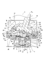
- the wheel of an automobile is supported rotatably with respect to the suspension device by a hub unit bearing 100 as shown in FIG.
- the hub unit bearing 100 is supported and fixed to an outer ring 102 that is coupled and fixed to a knuckle 101 that constitutes a suspension device in use and does not rotate, a wheel 103 that constitutes a wheel in use, and a braking rotator 104 such as a disk and a drum.
- a hub 105 that rotates together with the wheel 103 and the braking rotator 104 and a plurality of rolling elements 106 are provided.
- the outer ring 102 includes double-row outer ring raceways 107 a and 107 b and a stationary flange 108.
- the double row outer ring raceways 107 a and 107 b are formed on the inner peripheral surface of the intermediate part in the axial direction of the outer ring 102.
- the stationary flange 108 is formed at the axially intermediate portion of the outer ring 102 so as to protrude outward in the radial direction, and has support holes 109 that are screw holes at a plurality of locations in the circumferential direction.
- the outer ring 102 is coupled and fixed to the knuckle 101 by screwing a bolt 111 inserted through a through hole 110 formed in the knuckle 101 into the support hole 109 of the stationary flange 108 from the inside in the axial direction and further tightening.
- the hub 105 is disposed coaxially with the outer ring 102 on the radially inner side of the outer ring 102, and includes double-row inner ring raceways 112a and 112b and a rotating flange 113.
- the double-row inner ring raceways 112a and 112b are formed on the outer peripheral surface of the hub 105 at portions facing the double-row outer ring raceways 107a and 107b.
- the rotating flange 113 is formed in a portion of the hub 105 that is located on the outer side in the axial direction from the outer end portion in the axial direction of the outer ring 102 so as to protrude radially outward.
- a mounting hole 114 is provided.
- the serration portion formed near the proximal end of the stud 115 is press-fitted into the mounting hole 114 of the rotating flange 113, and the intermediate portion of the stud 115 is press-fitted into the through-hole 116 formed in the braking rotator 104.
- the braking rotator 104 is coupled and fixed to the rotating flange 113 of the hub 105.
- the male screw portion formed at the tip of the stud 115 being inserted through the through hole 117 formed in the wheel 103, the nut 118 is screwed into the male screw portion and further tightened, whereby the wheel is attached to the rotating flange 113. Bonded and fixed.
- a plurality of rolling elements 106 are arranged between the outer ring raceways 107a and 107b in the double row and the inner ring raceways 112a and 112b in the double row in such a manner that a plurality of rolling elements are held by the retainers 119 in each row. Has been.
- the hub 105 is made up of a hub body 120 having an inner ring raceway 112a on the axially outer side (left side in FIG. 13) and an inner ring 121 having an inner ring raceway 112b on the inner side in the axial direction (right side in FIG. 13). It is configured by coupling and fixing. Specifically, the axially inner end of the cylindrical portion 122 provided at the axially inner end of the hub main body 120 in the state where the inner ring 121 is externally fitted to the portion near the axially inner end of the hub main body 120 is the radial direction. The hub main body 120 and the inner ring 121 are coupled and fixed by pressing the inner end surface in the axial direction of the inner ring 121 with a caulking portion 123 formed by plastic deformation outward.
- FIG. 14 shows a swing caulking device 124 described in Japanese Patent Laid-Open No. 2001-241450.
- the swing caulking device 124 includes a pressing die 126 having a processing portion 125 at a tip end portion (lower end portion in FIG. 14), and a holder for supporting the hub main body 120 so that the central axis of the hub main body 120 is directed vertically. 127.
- the pressing die 126 is swung and rotated by the actuator while pressing the hub body 120 upward via the holder 127.
- the pressing die 126 is rotated around the central axis of the hub main body 120 in a state where the central axis of the pressing die 126 is inclined by a predetermined angle ⁇ with respect to the central axis of the hub main body 120.
- the center axis of the pressing die 126 is swung around the center axis of the hub main body 120 like a locus of the center axis due to precession.
- the caulking portion 123 is formed by the rocking caulking process performed using the rocking caulking device 124, a part in the circumferential direction of the pressing die 126 presses the axial inner end portion of the cylindrical portion 9.
- the machining operation for the caulking portion 123 proceeds partially and continuously in the circumferential direction. Therefore, the swing caulking process can reduce the load required for the machining as compared with the case where the caulking portion 123 is formed by a general forging press.
- Japanese Patent Laid-Open No. 2013-132678 is not intended to form a caulking portion at the inner end in the axial direction of the hub body of the hub unit bearing, but a convex spherical portion (semispherical) having a partially convex spherical shape. Part) and a concave concave spherical part (receiving surface) that are partly concave and spherical, by engaging the processing reaction force applied to the pressing die (upper mold) during swing forging. Is disclosed.
- the central axis of the pressing die is inclined by a predetermined angle with respect to the central axis of the concave spherical surface portion, so that a part of the concave spherical surface portion is a convex spherical surface portion.
- the spherical engaging portion is forcibly lubricated, and the lubricating oil that has flowed out (exuded) radially outward from the spherical engaging portion falls down from the concave spherical portion, adversely affecting the surrounding environment of the workpiece. May affect.
- the present invention can reduce the influence of the surrounding environment, for example, by preventing the lubricating oil flowing out from the spherical engaging portion between the convex spherical portion and the concave spherical portion from adversely affecting the surrounding environment of the workpiece.
- An object of the present invention is to realize a structure of an oscillating device that is advantageous for appropriate environmental protection against dynamic motion.
- the swing machining apparatus includes a reference axis, a support jig, a spherical seat with a shaft, a concave spherical seat, and a cover.
- the support jig is for supporting a workpiece so as to be coaxial with the reference axis.
- the spherical seat with a shaft has a central axis inclined with respect to the reference axis, and is formed at a processing portion formed at one end portion in the axial direction and an intermediate portion in the axial direction, and faces the other end side in the axial direction. And a partially spherical convex spherical portion.
- the concave spherical seat is an insertion hole through which the other end portion in the axial direction of the spherical seat with shaft (a portion of the spherical seat with shaft positioned closer to the other end side in the axial direction than the convex spherical portion); A convex spherical surface and a concave spherical surface engaged with the spherical surface.
- the cover prevents the lubricating oil that lubricates the spherical engaging portion between the convex spherical portion and the concave spherical portion from adversely affecting the surrounding environment of the workpiece.
- the oscillating device has a surface intersecting a predetermined axis, and is disposed to face the surface of the support, the support that supports the workpiece, and the workpiece.
- a cover For example, in an oscillating machining apparatus, the axis of the oscillating body is inclined with respect to the reference axis, and the inclined axis moves around the reference axis. The relative rotation of the cover is advantageous for proper environmental protection against rocking motion.
- the position and / or area of the cover target region changes with the change in posture of the rocking body during the rocking motion.
- the changing target area is appropriately covered by the cover that rotates relative to the oscillator.
- the cover since the cover has an asymmetric peripheral wall around the predetermined axis, the predetermined area is appropriately protected against the swinging motion of the swinging body.
- the cover may include a cover body and a first member that is provided at at least one location of the cover body and is pushed by the rocking body in accordance with the rocking motion of the rocking body. it can. In this case, a force is applied to the cover via the first member based on the movement of the rocking body.
- the cover can be rotated by the force received from the rocking body.
- the hub includes an inner ring and a hub body.
- the inner ring has an inner ring raceway on the inner side in the axial direction of the double row inner ring raceways on an outer peripheral surface.
- the hub main body is provided on the outer peripheral surface of the axially intermediate portion directly or via another member, and the inner ring raceway on the outer side in the axial direction of the double row inner ring raceways, and the inner ring raceway on the outer side in the axial direction.
- a cylindrical portion that is present on the inner side in the axial direction and that externally fits the inner ring, and a caulking portion that is bent radially outward from the axial inner end portion of the cylindrical portion and that restrains the inner end surface in the axial direction of the inner ring. And have.
- the cylindrical portion provided at the axially inner end portion of the hub body before the caulking portion is formed using the swing processing apparatus as described above.
- the caulking portion is formed by plastically deforming in a radially outward direction.
- an automobile that is an object of an automobile manufacturing method includes a hub unit bearing.
- the hub unit bearing is manufactured by the hub unit bearing manufacturing method as described above.
- the oscillating machining apparatus of the present invention for example, lubricating oil that has flowed out of the spherical engaging portion between the convex spherical surface portion and the concave spherical surface portion is prevented from adversely affecting the surrounding environment of the workpiece.
- the effects of the surrounding environment can be reduced.
- the oscillating device of the present invention is advantageous for appropriate environmental protection against oscillating motion.
- FIG. 1 is a schematic cross-sectional view showing an oscillating device (oscillating forging device) according to a first example of an embodiment of the present invention.
- FIG. 2 is an enlarged cross-sectional view of a main part of FIG.
- FIG. 3 is a cross-sectional view for explaining a cover manufacturing method.
- FIG. 4 is a diagram showing the result of a simulation performed to confirm the effect of the present invention.
- FIG. 5 is a cross-sectional view showing another example of the coupling structure of the base plate and the pressing die.
- FIG. 6 is an enlarged sectional view of an essential part showing an oscillating device (oscillating forging device) according to a second example of the embodiment of the present invention.
- FIG. 7 is a perspective view showing the cover taken out.
- FIG. 8 is a view similar to FIG. 2 showing an oscillating device (oscillating forging device) according to a third example of the embodiment of the present invention.
- FIG. 9 is a side view showing the spherical seat with shaft, the cover and the conversion mechanism, and the guide ring, and the cover portion of the conversion mechanism being removed.
- FIG. 10 is a perspective view showing the cover, the conversion mechanism, and the base plate.
- FIG. 11 is a view similar to FIG. 10 with the cover of the conversion mechanism removed.
- FIG. 12 is a schematic diagram illustrating another example of the conversion mechanism.
- FIG. 13 is a cross-sectional view showing an example of a conventionally known wheel support rolling bearing unit.
- FIG. 14 is a cross-sectional view showing an example of a conventional structure of an oscillating device (oscillating forging device).
- the oscillating device 15 of this example is an oscillating forging device, and is plastic so that the axially inner end of the cylindrical portion 9 of the hub body 7 is squeezed outward in the axial direction and expanded radially outward. It is used for swing caulking that is deformed (caulked and expanded) to form the caulking portion 10.
- the hub 3 of the hub unit bearing 1 which is a workpiece has a pair of inner rings 8a and 8b fitted on the outer peripheral surface of the axially intermediate portion of the hub body 7, and the hub body 7 By restraining the axial inner end surface of the inner ring 8b on the inner side in the axial direction by a caulking portion 10 formed by plastically deforming the axial inner end portion of the cylindrical portion 9 provided in the axial inner end portion radially outward.
- the hub unit bearing 1 which is the subject of this example is a hub body having an outer ring raceway on the outer periphery in the axial direction on the outer peripheral surface in the axial direction as in the hub unit bearing 100 shown in FIG. It can also comprise.
- a tapered roller is used as the rolling element 6, but a ball may be used as in the hub unit bearing 100 shown in FIG.
- the axially inner side means the center in the width direction of the vehicle in a state where the hub unit bearing 1 is assembled to the suspension device, and conversely, the hub unit bearing 1 is assembled to the suspension device.
- the outer side in the width direction of the vehicle in the state where it is in contact is called the outer side in the axial direction.
- the swing forging device 15 of this example is placed on the floor surface of a factory or the like, and is not displaced during the operation of the swing forging device 15, a support jig (support) 17, and a spherical seat with a shaft. (Oscillator) 18, concave spherical seat 19, drive mechanism 38, outer ring rotating mechanism 43, oil receiver 20, and cover 21. Further, the rocking forging device 15 has a reference axis C that serves as a processing reference. In this example, the reference axis C is directed in the vertical direction and is disposed at the center of the swing forging device 15.
- the support jig 17 is configured so that the hub unit bearing (workpiece, workpiece) 1 is positioned so that the central axis of the hub unit bearing 1 and the reference axis C are coaxial, and the hub unit bearing 1 is axially outside.
- the end portion is supported so that it faces downward, and the axially inner end portion faces upward. That is, the support jig 17 has, on the upper surface, a support concave portion 22 that can be engaged (fitted) with the axially outer end portion of the hub body 7 and without shakiness in the radial direction.
- Such a support jig 17 is supported at the lower end of the frame 16 at the upper end of a lifting platform 23 that is installed so as to be able to move up and down along the reference axis C.
- the shaft-attached spherical seat 18 has a center axis O 18 inclined with respect to the reference axis C, and has a machining portion 12 formed at one axial end (the lower end in FIGS. 1 and 2), and an axial direction.
- a spherical seat with shaft (oscillating body) 18 is arranged to face the surface of the support jig 17 intersecting a predetermined axis, and oscillates with respect to the workpiece (workpiece) 1.
- the predetermined axis is, for example, the reference axis C and / or the center axis (rotation axis) of the cover 21.
- one end side in the axial direction is the tip portion where the processed portion 12 is formed. 1 and FIG. 2 and the other end side in the axial direction is the opposite side to the tip portion where the processed portion 12 is formed, and the upper right side of FIG. 1 and FIG. Say the side.
- the inclination angle ⁇ of the central axis O 18 of the spherical seat with shaft 18 with respect to the reference axis C is preferably 15 degrees or more and 45 degrees or less, more preferably 15 degrees or more and 30 degrees or less, and 15 degrees or more and 18 degrees. More preferably, it is as follows.
- the tilt angle ⁇ can be 5, 10, 12, 14, 16, 18, 20, 25, 30, 35, 40, or 45 degrees.
- the inclination angle ⁇ is 15 degrees.
- the surface roughness of the portion of the outer peripheral surface of the cylindrical portion 9 that is in contact (fitting) with the inner peripheral surface of the inner ring 8b can be improved, and the durability of the hub unit bearing 1 can be improved. Improvements can be made. Further, if the inclination angle ⁇ is 30 degrees or less, when the caulking portion 10 is formed by swing caulking, the amount of wear of the caulking portion 10 can be reduced, and the durability of the hub unit bearing 1 can be reduced. Improvements can be made.
- the inclination angle ⁇ can be less than 15 degrees or greater than 45 degrees. When the hub unit bearing 1 is manufactured using the swing forging device of the present invention, the inclination angle ⁇ is preferably 15 degrees or more and 18 degrees or less.
- the spherical seat (oscillator) 18 with a shaft is configured by combining a shaft body 25, a convex spherical seat 26, a base plate 27, and a pressing die (processing tool) 13.
- the shaft body 25 includes a shaft portion 28, a flange portion 29 that protrudes radially outward from the outer peripheral surface of one end portion in the axial direction of the shaft portion 28, and a first positioning recess 30 formed in the center portion of the one end surface in the axial direction.
- the convex spherical seat 26 includes a convex spherical portion 24 formed on the side surface on the other end side in the axial direction, a fitting concave portion 31 formed on the side surface on the one end side in the axial direction, and a through hole 32.
- the fitting recess 31 can fit the flange portion 29 of the shaft body 25 in the radial direction without rattling.
- the through hole 32 is formed so as to penetrate the central portion of the convex spherical seat 26 in the axial direction, and the axial middle portion of the shaft portion 28 of the shaft body 25 (the axial direction of the portion where the flange portion 29 is formed, etc.) The portion adjacent to the end side) can be inserted without shakiness in the radial direction.
- the base plate 27 is formed on the side surface on the other end side in the axial direction, and has a first positioning convex portion 33 that can be fitted to the first positioning concave portion 30 of the shaft main body 25 without looseness in the radial direction, And a second positioning protrusion 34 formed on the side surface on one side in the direction.
- the pressing die (processing tool, oscillating body) 13 is formed on the processing portion 12 formed on one end portion in the axial direction, on the side surface on the other end side in the axial direction, and on the second positioning convex portion 34 of the base plate 27 and the diameter. And a second positioning recess 66 that can be fitted without shakiness in direction. That is, a conical protruding portion 57 is formed at the central portion of the side surface on one end side in the axial direction of the pressing die 13, and a concave groove 58 having a circular arc cross section is formed around the protruding portion 57 so as to surround the entire circumference of the protruding portion 57. By forming in this way, the processing portion 12 is configured.
- the pressing die (working tool, rocking body) 13 is arranged to face the surface of the support jig 17 intersecting with a predetermined axis, and swings with respect to the workpiece (workpiece) 1.
- the shaft main body 25 and the convex spherical seat 26 are inserted or press-fitted in the axial direction intermediate portion of the shaft portion 28 into the through-hole 32 without rattling in the radial direction, and the flange portion 29 is inserted into the fitting recess 31 in the radial direction. It is combined by fitting inside without rattling. Further, the base plate 27 and the pressing die (processing tool) 13 fit the second positioning convex portion 34 of the base plate 27 into the second positioning concave portion 66 of the pressing die 13 without rattling in the radial direction.
- the bolts inserted through the circular holes formed in the base plate 27 are coupled and fixed by, for example, screwing into the screw holes formed in the base plate 27.
- the assembly of the shaft main body 25 and the convex spherical seat 26 which is the main body portion, and the assembly of the base plate 27 and the pressing die 13 are combined with the first positioning concave portion 30 and the first positioning convex portion 33.
- the spherical seat 18 with a shaft is configured by engaging the projections and depressions and coupling them with a coupling member such as a bolt.
- the base plate 27 a and the pressing die (processing tool) 13 a are the base end portion (the other end portion in the axial direction; the upper end portion in FIG. 5) of the pressing die 13 a and the one axial end portion of the base plate 27 a.
- the bolt is inserted into the holding recess 67 formed on the side surface without rattling and the bolt inserted through the circular hole formed in the pressing die 13a is screwed into the screw hole formed in the base plate 27a. You may do it.
- the method for coupling and fixing the shaft main body 25, the convex spherical seat 26, the base plates 27 and 27a and the pressing dies 13 and 13a is not limited to the method using bolts, and can be coupled and fixed by press-fitting or retaining rings, for example. . Further, a part of the shaft body 25, the convex spherical seat 26, the base plate 27, and the pressing die 13 can be formed integrally, or the entire spherical seat 18 with shaft can be formed integrally.
- the concave spherical seat 19 is inserted through an axially intermediate portion of the spherical seat with shaft 18 (a portion of the shaft portion 28 of the shaft body 25 that protrudes from the convex spherical portion 24 of the convex spherical seat 26 toward the other axial end). And a partially spherical concave spherical surface portion 36 that engages with the convex spherical surface portion 24 of the spherical seat 18 with shaft.
- the concave spherical seat 19 is supported and fixed at an intermediate portion in the vertical direction in the frame 16.
- the spherical spherical surface 18 with shaft is pivoted about the reference axis C by spherically engaging the convex spherical portion 24 of the spherical spherical seat 18 with the concave spherical portion 36 of the concave spherical seat 19. (Oscillating rotation, revolution), and allowing the spherical seat with shaft 18 to change its posture (rotational motion, rotation) around its center axis O18, and when performing the swing forging, The processing reaction force applied to the spherical seat with shaft 18 can be supported.
- the convex spherical portion 24 and the concave spherical portion 36 The spherical engaging portion is forcibly lubricated by lubricating oil discharged from a plurality of discharge ports formed in the concave spherical portion 36.
- the insertion hole 35 of the concave spherical seat 19 is a tapered hole whose inner diameter dimension increases toward the upper side. Further, a portion of the frame 16 adjacent to the upper side of the insertion hole 35 of the concave spherical seat 19 and the portion where the intermediate portion in the axial direction of the spherical seat with shaft 18 is inserted has a stepped inner diameter as it goes upward. The stepped hole 37 becomes larger.
- the inner diameter dimensions of the insertion hole 35 and the stepped hole 37 are such that when the spherical seat with shaft 18 swings around the reference axis C, the inner peripheral surface of the insertion hole 35 and the stepped hole 37 and the spherical seat with shaft. It is regulated so that it does not interfere with the outer peripheral surface of 18.
- a portion of the frame 16 adjacent to the upper side of the insertion hole 35 of the concave spherical seat 19 may be a tapered hole whose inner diameter increases toward the upper side.
- the drive mechanism 38 is for applying a driving force for the shaft-equipped spherical seat 18 to swing and rotate about the reference axis C to the other axial end of the shaft-equipped spherical seat 18.
- the drive mechanism 38 is supported and fixed to the upper end portion in the frame 16 and the other axial end portion protruding upward from the stepped hole 37 in the shaft portion 28 of the shaft body 25 of the spherical seat 18 with shaft. In addition, it is connected so that a driving force can be applied.
- the drive mechanism 38 includes a rotating body 39 and a bearing 40.
- the rotating body 39 is supported at the upper end portion in the frame 16 through the bearing device 41 so as to be able to rotate only about the reference axis C.
- the rotating body 39 has a holding hole 42 that is inclined in a direction toward the radially outer side as it goes upward at one position in the circumferential direction of the radially intermediate portion.
- the inclination angle of the central axis of the holding hole 42 with respect to the reference axis C is the same as the inclination angle ⁇ of the central axis O 18 of the spherical seat with shaft 18 with respect to the reference axis C.
- an output part of a motor (not shown) for rotating the rotating body 39 around the reference axis C is connected to the rotating body 39 directly or via a speed reducer.
- the bearing 40 is provided between the inner peripheral surface of the holding hole 42 and the outer peripheral surface of the other axial end of the spherical seat 18 with shaft, and the axial direction of the spherical seat 18 with shaft with respect to the holding hole 42.
- the end is rotatably supported.
- a self-aligning roller bearing is used as the bearing 40.
- a rolling bearing such as a deep groove ball bearing or an angular ball bearing can be used.
- the outer ring rotating mechanism 43 rotates and revolves the rolling element 6 by rotationally driving the outer ring 2 of the hub unit bearing 1 to form the caulking portion 10, thereby forming an outer ring raceway 4 a provided in the outer ring 2, This is to prevent indentation from being formed on the inner ring raceways 5a and 5b provided in the hub 4b.
- the outer ring rotating mechanism 43 is capable of rotating slightly in synchronism with the drive ring 44 and an electric motor (not shown), a drive ring 44 that is rotationally driven by the electric motor, and allowing the drive ring 44 to move up and down slightly. And a supported driving jig 45.
- the drive ring 44 and the drive jig 45 are combined via a ball spline 48.
- An inward flange portion 68 protruding radially inward is provided at the upper end portion of the drive ring 44, and a torsion coil is provided between the lower side surface of the inward flange portion 68 and the upper end surface of the drive jig 45.
- a spring 69 is sandwiched.
- the outer ring rotating mechanism 43 is configured such that the outer ring 2 can be rotationally driven by rotating the driving jig 45 engaged with the coupling flange 46 of the outer ring 2 by an electric motor via the driving ring 44.
- the drive ring 44 is attached to the frame 16 around the drive ring 44 via a radial bearing 47, an L-shaped cross-section guide ring 49 and an oil receiver 20 in order from the radially inner side. On the other hand, it is supported rotatably.
- the outer ring rotating mechanism 43 is not limited to the above-described configuration, and various configurations can be adopted as long as the rolling element 6 can rotate and revolve by rotating the outer ring 2.
- the oil receiver 20 is configured to have a substantially L-shaped cross section, and is supported and fixed around one axial end portion (lower end portion) of the concave spherical seat 19, and the radial direction from the lower end portion of the cylindrical portion 50. And an annular portion 51 bent inward.
- the annular portion 51 has an annular recess 52 on the upper surface thereof that faces the outer peripheral edge of the concave spherical portion 36 of the concave spherical seat 19 over the entire circumference.
- the spherical engaging portion lubricates the convex spherical portion 24 of the spherical seat with shaft 18 and the concave spherical portion 36 of the concave spherical seat 19 and flows out (seeps out) from the outer peripheral edge of the spherical engaging portion.
- Most of the lubricating oil moves downward along the concave spherical surface portion 36 and hangs down from the outer peripheral edge portion of the concave spherical surface portion 36 into the annular concave portion 52.
- Lubricating oil dripping into the annular recess 52 is recovered from an oil passage hole (not shown) formed in the oil receiver 20, and again from the nozzle to the convex spherical portion 24 and the concave spherical portion 36 through the lubricating oil flow path. Supplied to the spherical engaging portion.
- the cover 21 can be formed of, for example, rubber, a synthetic resin, a light alloy such as an aluminum alloy, an iron-based metal such as carbon steel, or another material.
- the cover 21 includes an obliquely cut cylindrical (bamboo split shape) cover portion (cover body) 53 obtained by obliquely cutting a cylinder, and an inward flange portion 54 that is bent radially inward from the upper end portion of the cover portion 53.
- the cover part (cover body) 53 has an asymmetric peripheral wall around a predetermined axis.
- the peripheral wall has a different axial length (wall height) depending on a circumferential position around a predetermined axis.
- the cover part (cover body) 53 is parallel to a shaft end surface arranged parallel to the first virtual surface perpendicular to the predetermined axis and a second virtual surface inclined with respect to the predetermined axis. And a peripheral wall having a shaft end face disposed on the surface.
- the second angle of inclination of the virtual plane beta phi with respect to the first imaginary plane alpha is the same as the inclination angle ⁇ of the central axis O 18 of the shaft with spherical seat 18 (refer to FIG. 1) with respect to the reference axis C.
- the central axis O 62 of the cylindrical member 62 (the central axis O 21 of the cover 21 ) is disposed coaxially with the central axis O 18 of the spherical seat 18 with shaft. .
- the other axial side of the inward flange portion 54 is present on the first imaginary plane alpha 1 perpendicular to the center axis O 18 of the shaft with spherical seat 18 , the lower surface of the cover portion 53 is present on the second virtual plane beta 1 orthogonal to the reference axis C.
- the cover 21 has a radially inner end portion of the inward flange portion 54 on the outer peripheral surface of the base plate 27 of the spherical seat 18 with a shaft via a rolling bearing 55 which is a radial rolling bearing such as a four-point contact type ball bearing. And is supported rotatably. Further, the lower end surface of the cover portion 53 of the cover 21 is arranged around the hub unit bearing 1 as a workpiece and supported by the frame 16 via a plurality of radial rolling bearings 60. It is placed on the top surface of the.
- the inner ring of a plurality of radial rolling bearings 60 is arranged at the upper end of the guide ring 49 with the respective center axes arranged radially in the direction centered on the reference axis C. It is supported at equal intervals in the circumferential direction.
- the lower end surface of the cover part 53 of the cover 21 is mounted on the upper surface (upper part of the outer peripheral surface of the outer ring) of the outer ring of the plurality of radial rolling bearings 60.
- the hub body 7 and the hub unit bearing 1 before the caulking portion 10 is formed are connected.
- the central axis of the hub body 7 and the reference axis C are coaxial, and the axially outer end portion of the hub unit bearing 1 faces downward, and also in the axial direction.
- the hub body 7 is supported by the support jig 17 without the backlash in the radial direction so that the end faces upward.
- the spherical seat with shaft 18 is swung and rotated about the reference axis C.
- the spherical seat with shaft 18 rotates around its central axis O 18 based on the frictional force acting on the contact portion between the concave groove 58 of the processed portion 12a and the inner end portion in the axial direction of the cylindrical portion 9. (Spin).
- the spherical engaging portion between the convex spherical surface portion 24 and the concave spherical surface portion 36 is forcibly lubricated with lubricating oil discharged from a plurality of discharge ports formed in the concave spherical surface portion 36.
- the caulking portion 10 is formed by gradually plastically deforming the inner end portion in the axial direction of the cylindrical portion 9.
- the swing angle (inclination angle ⁇ ) of the spherical seat 18 with shaft when the caulking portion 10 is formed by dynamic forging is set to 15 degrees or more and 30 degrees or less, the maximum processing load at the time of performing the swing forging is set. Can be kept low.
- the outer ring rotating mechanism 43, the radial bearing 47, and the axially inner end portion of the hub unit bearing 1 and the periphery of the hub unit bearing 1 are provided.
- the upper end portion of the guide ring 49 is covered with the cover 21. Therefore, even when the spherical engaging portion between the convex spherical portion 24 and the concave spherical portion 36 is forcibly lubricated and a part of the lubricating oil that has flowed out (exuded) from the outer peripheral edge portion of the spherical engaging portion drips down.
- the cover 21 can prevent the lubricating oil from adhering to the inner end portion in the axial direction of the hub unit bearing 1 and the upper end portions of the outer ring rotating mechanism 43, the radial bearing 47 and the guide ring 49. That is, it is possible to prevent the surrounding environment of the hub unit bearing 1 from being adversely affected by the lubricating oil.
- the lubricating oil dripping from the concave spherical surface portion 36 is guided by the outer peripheral surface of the cover 21 into the annular concave portion 52 of the oil receiver 20 and is collected from the oil passage hole.
- the axis of the oscillating body (the spherical seat with shaft 18, the pressing die 13 (13a)) is inclined with respect to the reference axis, and the inclined axis moves around the reference axis.
- the relative rotation of the cover 21 is advantageous for appropriate environmental protection against rocking motion. For example, the position and / or area of the cover target region changes with the posture change of the spherical seat with shaft (oscillating body) 18 during the swinging motion.
- the changing target region is appropriately covered by the cover 21 that rotates relative to the shaft-attached spherical seat (oscillator) 18. Since the cover 21 has the asymmetric peripheral wall 53 around the predetermined axis, the predetermined area is appropriately protected against the swinging motion of the spherical seat with shaft (swinging body) 18.
- the radially inner end portion of the inward flange portion 54 of the cover 21 is rotatably supported on the outer peripheral surface of the base plate 27 of the shaft-attached spherical seat 18 via the rolling bearing 55, and the cover One axial end portion 21 is rotatably mounted on the upper surface of the guide ring 49 via a plurality of radial rolling bearings 60. For this reason, the cover 21 can be smoothly rotated with the pivoting rotation of the spherical seat 18 with a shaft.
- the axial dimension of the cover portion 53 of the cover 21 is always close to the portion where the distance between the outer peripheral surface of the base plate 27 of the spherical seat 18 with shaft and the upper surface of the guide ring 49 is close. A short part can be located.
- the oscillating device of the present invention is not limited to this, but includes various types such as a hub unit bearing and a bevel gear (bevel gear) having a face spline at the axial inner end of the hub, and a ring-shaped member having a flange at the axial end. It can be used for rocking forging of workpieces.
- the oscillating device of the present invention can also be applied to a device that performs processing other than forging.
- the cover 21a is a cylindrical shape having a pair of rim portions 64a and 64b each having an annular shape, and a bellows-like bellows portion extending over the entire circumference between the rim portions 64a and 64b.
- the cylindrical portion 65 is made of a flexible material such as rubber or cloth.
- the cylindrical portion 65 does not sag when the axial dimension is expanded or contracted, and even if it occurs, the cylindrical portion 65 swings around the reference axis C of the spherical seat with shaft 18 (see FIGS. 1 and 2). If it can be suppressed to the extent that it does not interfere with rotation, it is not necessary to have a bellows shape, and it may be a simple cylindrical shape or a conical cylindrical shape.
- the upper rim portion 64a of the cover 21a is supported and fixed to the outer peripheral surface of one axial end portion (lower end portion) of the flange portion 29a of the shaft body 25a, and the lower rim portion 64b is thrust-rolled.
- the bearing 63 is rotatably mounted on the upper surface of the guide ring 49.
- the lower rim portion 64b is formed on the upper surface of the outer ring of a plurality of radial rolling bearings having a central axis arranged in a radial direction around the reference axis C as in the structure of the first example of the embodiment. It can also be placed.
- the outer ring rotation that exists in the axial direction inner end of the hub unit bearing 1 and around the hub unit bearing 1 during the processing of the caulking portion 10 (see FIGS. 1 and 2).
- the upper ends of the mechanism 43, the radial bearing 47 (see FIG. 1) and the guide ring 49 can be covered with the cover 21a. Therefore, it is possible to prevent the peripheral environment of the hub unit bearing 1 from being adversely affected by the lubricating oil flowing out from the spherical engaging portion between the convex spherical portion 24 and the concave spherical portion 36.
- the phase in the circumferential direction coincides with a portion where the distance between the outer peripheral surface of the flange portion 29a and the upper surface of the guide ring 49 is close (see FIG. The portion surrounded by the chain line A of 6) is deformed so as to enter the annular recess 52 with a slight slack while reducing the axial dimension.
- the lower end portion of the cover 21a is rotatably supported with respect to the guide ring 49, but instead of this, or in addition to this, the upper end portion of the cover 21a is connected to the spherical seat with shaft 18 ( The shaft main body) can also be configured to be rotatably supported.
- Other configurations and operational effects are the same as in the first example of the embodiment.
- [Third example of embodiment] 8 to 11 show a third example of the embodiment of the present invention.
- the cover 21b of the present example includes a beveled cylindrical cover portion 53a and an inward flange portion 54 that is bent radially inward from the upper end portion of the cover portion 53a.
- the cover 21 mounts the lower end surface of the cover 53a on the upper surface of the guide ring 49 via a plurality of radial rolling bearings 60, as in the first example of the embodiment.
- the radially inner end portion of the inward flange portion 54 is not supported with respect to the spherical seat 18 with a shaft, and on the outer peripheral surface of the base plate 27, Opposite the entire circumference through a gap.
- a spherical seat with shaft (oscillating body) 18 is arranged to face the surface of the support jig 17 intersecting a predetermined axis, and oscillates with respect to the workpiece (workpiece) 1.
- the predetermined axis is, for example, the reference axis C and / or the center axis (rotation axis) of the cover 21.
- the swing forging device 15 of this example includes a conversion mechanism 70.
- the conversion mechanism 70 is disposed between the spherical seat with shaft 18 and the cover 21b, and covers the force input as the spherical seat with shaft 18 swings and rotates (revolves) about the reference axis C. 21b is converted into a force for rotating around the reference axis C.
- the conversion mechanism 70 is out of the longest portion (the portion surrounded by the chain line ⁇ in FIG. 9) and the shortest portion (the portion surrounded by the chain line ⁇ in FIG. 9) in the cover portion 53a of the cover 21b.
- the outer peripheral surface of the cover portion 53a and the other end surface in the axial direction are formed in a portion slightly deviated in the circumferential direction around the reference axis C from the portion having the shortest axial dimension in the cover portion 53a of the cover 21b.
- a notch 71 is formed at an opening (a surface indicated by a chain line arrow ⁇ facing obliquely upper left in FIG. 9), and the conversion mechanism 70 is disposed inside the notch 71.
- the conversion mechanism 70 includes a casing 72, an input member (first member, roller) 73, and an output mechanism 74.
- the conversion mechanism 70 is provided on the cover 21 b, and the cover 21 b includes the conversion mechanism 70.
- the cover 21b is provided in at least one place of the cover part (cover body) 53a and the cover part 53a.
- the cover 21b moves to the spherical seat with shaft (oscillator) 18 as the spherical seat with shaft (oscillator) 18 swings.
- An input member (first member) 73 to be pushed is provided.
- the casing 72 is formed in a substantially trapezoidal shape when viewed from the side, and includes an accommodation recess 75 that is open on the upper surface and is recessed in the axial direction of the reference axis C.
- the casing 72 is supported and fixed inside the notch 71 of the cover 21b.
- the casing 72 includes a first casing element 76 and a second casing element 77.
- the first casing element 76 includes a substantially trapezoidal plate-like side plate portion 78, a pair of wall portions 79 a and 79 b that protrude from both end portions (left and right end portions in FIG. 9) of the inner surface of the side plate portion 78, and the side plate portion 78. And a bottom portion 80 that projects from the lower end portion of the inner side surface and connects the lower end portions of the pair of wall portions 79a and 79b.
- the first casing element 76 has a pair of wall portions 79a, 79b on one side (right side in FIGS. 9 to 11) of the wall portion 79a near the lower end thereof, on both side surfaces (FIG. 9). (Both left and right side surfaces) and a tip end surface.
- the second casing element 77 has a substantially trapezoidal plate shape and has the same contour shape as the side plate portion 78 of the first casing element 76.
- the casing 72 has the first casing element 76 and the second casing in a state in which the inner surface of the second casing element 77 is abutted against the tip surfaces of the pair of walls 79 a and 79 b and the bottom 80 of the first casing element 76.
- the element 77 is coupled and fixed by screwing or the like.
- the input member 73 is configured in a cylindrical shape, and a virtual plane including a central axis including a central axis of the cover 21b and a portion having the longest axial dimension and the shortest portion of the cover portion 53a (the paper surface of FIG. 9). Are arranged in a direction perpendicular to the plane parallel to the surface.
- a radial ball bearing is used as the input member 73.
- the input member 73 is not limited to a radial ball bearing, but a cylindrical shape.
- the input member 73 has a part of its outer peripheral surface protruding from the opening of the receiving recess 75, and the other of the pair of walls 79 a and 79 b (see FIGS. 9 to 11) inside the receiving recess 75.
- a left side of the wall portion 79b is disposed so as to be capable of displacement in the axial direction of the reference axis C, that is, in the vertical direction.
- the central axis of the input member 73 is arranged in a direction orthogonal to the virtual plane including the central axis of the cover 21b and the longest and shortest portions of the cover portion 53a. ing.
- a portion of the outer peripheral surface of the input member 73 that protrudes from the opening of the housing recess 75 is a convex portion of the spherical seat 18 with shaft in a state where the conversion mechanism 70 is assembled between the spherical seat 18 with shaft and the cover 21b. It abuts against one axial end surface of the spherical seat 26.
- the output mechanism 74 includes an intermediate member (second member) 82 and an elastic member (third member) 83.
- the intermediate member 82 is configured in a cylindrical shape, and the central axis is arranged in a direction parallel to the central axis of the input member 73.
- a radial ball bearing is used as the intermediate member 82 as in the case of the input member 73.
- the input member 73 is not limited to a radial ball bearing, as long as the outer peripheral surface has a hardness that can prevent wear and plastic deformation (for example, a hardness of HRC 40 or more), and is not limited to a radial ball bearing.
- Columnar rollers can also be used.
- the intermediate member 82 is disposed inside the receiving recess 75 along the bottom surface of the receiving recess 75 (the upper surface of the bottom 80), in a direction perpendicular to the reference axis C and the central axis of the intermediate member 82, that is, in the horizontal direction (in FIG. It is arranged to be displaceable in the left-right direction).
- the elastic member 83 is disposed inside the recessed hole 81 and between the outer peripheral surface of the intermediate member 82 and the inner surface of the notch 71.
- a torsion coil spring is used as the elastic member 83.
- the elastic member 83 is not limited to this, and rubber or the like can also be used.
- the elastic member 83 is disposed inside the concave hole 81 provided in the first casing element 76.
- the intermediate member 82 is disposed so that the outer peripheral surface of the intermediate member 82 is in contact with the other end surface (the left end surface in FIG. 9) of the elastic member 83 and the upper surface of the bottom portion 80, and the input member 73 is The outer peripheral surface of 73 is disposed so as to contact the inner surface of the other wall portion 79 b and the outer peripheral surface of the intermediate member 82.
- the inner surface of the second casing element 77 is abutted against the pair of wall portions 79a and 79b and the front end surface of the bottom portion 80 of the first casing element 76, and the first casing element 76 and the second casing element 77 are Connect and fix with screws.
- the conversion mechanism 70 is supported and fixed inside the cutout portion 71 of the cover 21b.
- the above assembly procedure can be interchanged as long as no contradiction occurs. Specifically, for example, after the first casing element 76 and the second casing element 77 are coupled, the input member 73 and the intermediate member 82 are disposed inside the accommodating recess 75, and the elastic member 83 is recessed in the recess 81. It can also be arranged inside.
- the conversion mechanism 70 is arranged with respect to a virtual plane including the central axis of the cover 21b and the longest part and the shortest part of the cover part 53a.
- a buffer mechanism having the same configuration as that of the conversion mechanism 70 is further provided in a portion symmetrical to the portion.
- the spherical seat 18 with shaft is pivoted about the reference axis C to form the caulking portion 10 at the inner end in the axial direction of the hub body 7 by the swing forging device 15 of this example.
- the one end face in the axial direction of the convex spherical seat 26 of the seat 18 causes the input member 73 of the conversion mechanism 70 to move downward toward the front side in the rotational direction (right side in FIG. 9) about the reference axis C of the spherical seat 18 with shaft. It is pushed toward the direction of heading. Thereby, the input member 73 is displaced downward along the inner surface of the other wall portion 79b.
- the intermediate member 82 When the input member 73 is displaced downward, the intermediate member 82 is pushed by the input member 73, and the intermediate member 82 is displaced in the horizontal direction along the bottom surface of the housing recess 75.
- the intermediate member 82 When the intermediate member 82 is displaced in the horizontal direction, the inner surface of the cutout portion 71 of the cover 21b is pushed by the intermediate member 82 via the elastic member 83, and the cover 21b is a spherical surface with a shaft around the reference axis C.
- the seat 18 is rotated in the same direction as that of the rocking rotation.
- the axis of the oscillating body (the spherical seat 18 with shaft and the pressing die 13) is inclined with respect to the reference axis, and the inclined axis moves around the reference axis.
- the relative rotation of the cover 21b is advantageous for appropriate environmental protection against swinging motion.
- the position and / or area of the cover target region changes with the posture change of the spherical seat with shaft (oscillating body) 18 during the swinging motion. Even in this case, the changing target area is appropriately covered by the cover 21b that rotates relative to the spherical seat with shaft (oscillator) 18.
- the input member (first member) 73 provided on the cover 21b is pushed by the spherical seat with shaft (oscillator) 18 based on the movement of the spherical seat with shaft (oscillator) 18, and the spherical seat with shaft (oscillator).
- the cover 21b is rotated by the force received from the moving body 18. Since the cover 21b has the asymmetric peripheral wall 53a around the predetermined axis, the predetermined area is appropriately protected against the swinging motion of the spherical seat with shaft (swinging body) 18.
- the cover 21b can be converted into a force for rotating around the reference axis C. For this reason, the cover 21b can be smoothly rotated at the start of processing for forming the caulking portion 10 at the axially inner end portion of the hub body 7. That is, the initial torque at the start of machining by the swing forging device 15 can be suppressed to a small value.
- the conversion mechanism 70 is arranged with respect to a virtual plane including the central axis of the cover 21b and the longest part and the shortest part of the cover part 53a.
- a buffer mechanism having the same structure as that of the conversion mechanism 70 is provided in a portion symmetrical to the portion. For this reason, even if the rocking rotation about the reference axis C of the spherical seat 18 with shaft is stopped after the processing of the caulking portion 10 is completed, the other side surface in the axial direction of the inward flange portion 54 of the cover 21b is a convex spherical surface. It is possible to prevent the cover 21b from being deformed by vigorously colliding with one end surface of the seat 26 in the axial direction.
- the buffer mechanism is a protrusion that is formed integrally with the cover or separately from the cover and protrudes in the other axial direction than the other axial side surface of the inward flange portion 54. You can also.
- the intermediate member 82 of the output mechanism 74 constituting the conversion mechanism 70 is a member having a cylindrical outer peripheral surface.
- the input member 73 having a cylindrical outer peripheral surface is displaced downward. Accordingly, as long as it can be displaced in the horizontal direction along the bottom surface of the housing recess 75, for example, a wedge-shaped intermediate member 82a can be used as shown in FIG.
- Other configurations and operational effects are the same as in the first example of the embodiment.
- the oscillating device (15) includes a reference axis, a support jig (17), a spherical seat with shaft (18), a concave spherical seat (19), and covers (21, 21a, 21b). ).
- the support jig (17) is for supporting the workpiece (1) so as to be coaxial with the reference axis.
- the spherical seat with shaft (18) has a central axis inclined with respect to the reference axis, and is formed at a machining portion (12) formed at one end portion in the axial direction and an intermediate portion in the axial direction. And a partially spherical convex spherical surface portion (24) facing the other end side in the direction.
- the concave spherical seat (19) is the other end in the axial direction of the spherical seat with shaft (18) (the other end in the axial direction of the convex spherical portion (24) of the spherical seat with shaft (18)).
- a concave spherical portion (36) that is spherically engaged with the convex spherical portion (24).
- the cover (21, 21a, 21b) the lubricating oil that lubricates the spherical engagement portion between the convex spherical surface portion (24) and the concave spherical surface portion (36) is added to the surrounding environment of the workpiece (1). Prevent adverse effects.
- a guide ring (49) disposed around the workpiece (1) can be further provided.
- the cover (21, 21a, 21b) is arranged between the guide ring (49) and one axial portion of the spherical seat with shaft (18).
- the cover (21, 21a, 21b) has an oblique cylindrical cover (53) in which one end face in the axial direction is supported or placed on the guide ring (49) so as to freely rotate around the reference axis. 53a) and an inward flange portion (54) bent radially inward from the other axial end portion of the cover portion (53, 53a).
- One end face in the axial direction of the cover (53, 53a) is arranged at equal intervals in the circumferential direction around the reference axis in a state where the respective central axes are arranged in the radial direction around the reference axis. It can be mounted on the guide ring (49) via a plurality of arranged radial rolling bearings (60).
- the other axial side surface of the inward flange portion (54) is present on a first virtual plane orthogonal to the central axis of the spherical seat with shaft (18), and the axis of the cover portion (53, 53a).
- One direction end face can exist on a second virtual plane orthogonal to the reference axis.
- the radially inner end of the inward flange portion (54) can be rotatably supported by the rolling bearing (55) on one axial end portion of the spherical seat with shaft (18).
- the cover (21, 21a, 21b) may be provided with a conversion mechanism (70) that converts the force to be turned into a force for rotating about the reference axis.
- the conversion mechanism (70) may include an accommodation recess (75), an input member (73), and an output mechanism (74).
- the housing recess (75) is disposed at a position radially out of the central axis of the spherical seat (18) with the shaft in the cover (21, 21a, 21b), and the cover (21, 21a).
- the input member (73) is disposed in the receiving recess (75) so as to be capable of displacement in the axial direction of the reference axis, and the other side in the axial direction provided in the spherical seat with shaft (18) is arranged. It is pressed by the facing surface.
- the output mechanism (74) includes the cover (21, 21a, 21b) as the input member (73) is displaced toward the workpiece (1) with respect to the axial direction of the reference axis. Are pressed in the rotation direction about the reference axis.
- the output mechanism (74) is disposed in the housing recess (75) so as to be capable of displacement in a direction perpendicular to the axial direction of the reference axis and the central axis of the input member (73).
- a cylindrical or columnar intermediate member (82, 82a) whose outer peripheral surface is pressed by the input member (73), and between the intermediate member (82, 82a) and the side surface of the accommodating recess (75).
- the elastic member (83) arranged may be provided.
- a buffering mechanism (70) may be provided on a part opposite to the part where the conversion mechanism (70) is arranged.
- the buffer mechanism (70) is disposed between the spherical seat with shaft (18) and the cover (21, 21a, 21b), and the spherical seat with shaft (18).
- the cover (21, 21a, 21b) is made of a flexible material such as rubber or cloth, and / or the axial dimension is configured to be partially extensible with respect to the circumferential direction. can do.
- one end of the cover (21, 21a, 21b) in the axial direction is supported or placed on the guide ring (49) so as to freely rotate around the reference axis, and / or the cover.
- the other end in the axial direction of (21, 21a, 21b) can be freely rotated around the central axis of the spherical seat with shaft (18) to the one axial end portion of the spherical seat with shaft (18).
- the cover (21, 21a, 21b) may have a bellows part.
- the inclination angle of the central axis of the spherical seat with shaft (18) with respect to the reference axis is 15 degrees or more.
- the spherical seat with shaft (18) includes a shaft body (25, 25a), a base plate (27, 27a), and a pressing die (13).
- the shaft body (25, 25a) has a central axis inclined with respect to the reference axis, and the convex spherical portion (24).
- the base plate (27, 27a) has a holding recess (67) on the side surface on one end side in the axial direction, and is coupled and fixed to the side surface on one end side in the axial direction of the shaft body (25, 25a).
- the pressing die (13, 13a) has a processed portion (12, 12a) at one end portion in the axial direction, and the other end portion in the axial direction is fitted into the holding recess portion (67) without rattling.
- the base plate (27, 27a) is coupled and fixed to the base plate (27, 27a) in a state of positioning in the radial direction with respect to the base plate (27, 27a).
- the oscillating device (15) has a surface that intersects a predetermined axis, and supports the workpiece (1), the support (17), and the surface of the support (17).
- An oscillating body (18) arranged to face the workpiece (1) and oscillating with respect to the workpiece (1), and a cover (21, 21b) arranged to be rotatable around the predetermined axis.
- the cover (21, 21b) that rotates around the predetermined axis relative to the rocking body in accordance with the rocking motion.
- the cover (21, 21b) may have an asymmetric peripheral wall (53, 53a) around the predetermined axis.
- the cover (21, 21b) is provided in at least one place of the cover main body (53, 53a) and the cover main body (53, 53a), and the rocking body is accompanied by the rocking motion of the rocking body (18). And a first member (73) pushed by (18).
- a hub unit bearing (1) to be subjected to a hub unit bearing manufacturing method includes an outer ring (2) having a double row outer ring raceway on an inner peripheral surface, and a double row inner ring raceway on an outer peripheral surface. And a plurality of rolling elements (6) arranged in a freely rotatable manner in each row between the double row outer ring raceway and the double row inner ring raceway. .
- the hub (3) includes inner rings (8a, 8b) and a hub body (7).
- the inner rings (8a, 8b) have, on the outer peripheral surface, an inner ring raceway on the inner side in the axial direction of the double row inner ring raceways.
- the hub body (7) includes an inner ring raceway on the outer side in the axial direction of the inner ring raceway in the double row, and an inner ring on the outer side in the axial direction.
- the axial direction of the hub body (7) before the caulking portion (10) is formed using the swing processing device (15) as described above.
- the caulking portion (10) is formed by plastically deforming the cylindrical portion (9) provided at the inner end portion radially outward.
- an automobile that is a subject of an automobile manufacturing method includes a hub unit bearing (1).
- the hub unit bearing (1) is manufactured by the hub unit bearing manufacturing method as described above.
Landscapes
- Engineering & Computer Science (AREA)
- Mechanical Engineering (AREA)
- General Engineering & Computer Science (AREA)
- Forging (AREA)
- Rolling Contact Bearings (AREA)
- Mounting Of Bearings Or Others (AREA)
- Pivots And Pivotal Connections (AREA)
- Sealing Devices (AREA)
- Diaphragms And Bellows (AREA)
Priority Applications (4)
| Application Number | Priority Date | Filing Date | Title |
|---|---|---|---|
| CN201980015246.7A CN111770801B (zh) | 2018-02-26 | 2019-02-25 | 摆动加工装置、轮毂单元轴承的制造方法及汽车的制造方法 |
| JP2019538283A JP6624354B1 (ja) | 2018-02-26 | 2019-02-25 | 揺動加工装置、ハブユニット軸受の製造方法および自動車の製造方法 |
| EP19757158.1A EP3593921B1 (en) | 2018-02-26 | 2019-02-25 | Oscillating machining device, method for manufacturing hub unit bearing, and method for manufacturing automobile |
| US16/975,212 US11732751B2 (en) | 2018-02-26 | 2019-02-25 | Rotary machining apparatus, method of manufacturing hub unit bearing, and method of manufacturing vehicle |
Applications Claiming Priority (6)
| Application Number | Priority Date | Filing Date | Title |
|---|---|---|---|
| JP2018-032487 | 2018-02-26 | ||
| JP2018032487 | 2018-02-26 | ||
| JP2018054018 | 2018-03-22 | ||
| JP2018-054018 | 2018-03-22 | ||
| JP2019-018458 | 2019-02-05 | ||
| JP2019018458 | 2019-02-05 |
Publications (1)
| Publication Number | Publication Date |
|---|---|
| WO2019163982A1 true WO2019163982A1 (ja) | 2019-08-29 |
Family
ID=67687242
Family Applications (2)
| Application Number | Title | Priority Date | Filing Date |
|---|---|---|---|
| PCT/JP2019/006990 Ceased WO2019163982A1 (ja) | 2018-02-26 | 2019-02-25 | 揺動加工装置、ハブユニット軸受の製造方法および自動車の製造方法 |
| PCT/JP2019/007031 Ceased WO2019163986A1 (ja) | 2018-02-26 | 2019-02-25 | 揺動加工装置、ハブユニット軸受の製造方法および自動車の製造方法 |
Family Applications After (1)
| Application Number | Title | Priority Date | Filing Date |
|---|---|---|---|
| PCT/JP2019/007031 Ceased WO2019163986A1 (ja) | 2018-02-26 | 2019-02-25 | 揺動加工装置、ハブユニット軸受の製造方法および自動車の製造方法 |
Country Status (5)
| Country | Link |
|---|---|
| US (2) | US11732751B2 (https=) |
| EP (2) | EP3593920B1 (https=) |
| JP (5) | JP6624354B1 (https=) |
| CN (2) | CN111801178B (https=) |
| WO (2) | WO2019163982A1 (https=) |
Cited By (2)
| Publication number | Priority date | Publication date | Assignee | Title |
|---|---|---|---|---|
| JP2020121343A (ja) * | 2018-02-26 | 2020-08-13 | 日本精工株式会社 | 揺動加工装置、ハブユニット軸受の製造方法および自動車の製造方法 |
| CN113020521A (zh) * | 2021-03-03 | 2021-06-25 | 宁波铭匠智能设备有限责任公司 | 一种摆碾机摆头机构 |
Families Citing this family (9)
| Publication number | Priority date | Publication date | Assignee | Title |
|---|---|---|---|---|
| US11691241B1 (en) * | 2019-08-05 | 2023-07-04 | Keltech Engineering, Inc. | Abrasive lapping head with floating and rigid workpiece carrier |
| CN112228465B (zh) * | 2020-11-15 | 2022-06-10 | 浙江师范大学 | 一种自监测的球轴承 |
| CN113082877B (zh) * | 2021-04-13 | 2022-09-02 | 苏州西西环保科技有限公司 | 一种震打式除尘器 |
| CN115091281B (zh) * | 2022-07-14 | 2023-11-03 | 浙江晟禧精密机械科技有限公司 | 一种汽车轮毂轴承小内圈的加工系统及其加工方法 |
| CN115727239B (zh) * | 2022-11-16 | 2026-04-21 | 中山宝益五金塑胶制品有限公司 | 一种云台装置 |
| CN116357669A (zh) * | 2023-02-16 | 2023-06-30 | 浙江申发轴瓦股份有限公司 | 一种推力加载系统 |
| CN116900228B (zh) * | 2023-07-19 | 2024-04-19 | 河南中力明新材料有限公司 | 一种具有保温性能的铝合金锻造模具 |
| JP7792381B2 (ja) * | 2023-08-30 | 2025-12-25 | Ckd株式会社 | 傾き調整装置 |
| CN121474262B (zh) * | 2026-01-08 | 2026-04-14 | 人本股份有限公司 | 减震器轴承及其润滑织物弧长计算方法 |
Citations (10)
| Publication number | Priority date | Publication date | Assignee | Title |
|---|---|---|---|---|
| JPS5048841U (https=) * | 1973-09-04 | 1975-05-14 | ||
| JPH04200947A (ja) * | 1990-11-30 | 1992-07-21 | Fuji Car Mfg Co Ltd | 揺動鍛造プレス機 |
| JP2001241450A (ja) | 1999-12-20 | 2001-09-07 | Nsk Ltd | 車輪支持用転がり軸受ユニットとその製造方法 |
| WO2004001247A1 (ja) | 2002-06-24 | 2003-12-31 | Nsk Ltd. | 車輪支持用転がり軸受ユニットの製造方法及び製造装置 |
| JP2013091067A (ja) | 2011-10-24 | 2013-05-16 | Toyota Motor Corp | 揺動鍛造装置及び揺動鍛造方法 |
| JP2013132678A (ja) | 2011-12-27 | 2013-07-08 | Yutaka Seimitsu Kogyo Ltd | 揺動鍛造方法および揺動鍛造装置 |
| JP2016165735A (ja) * | 2015-03-09 | 2016-09-15 | 株式会社デンソー | 揺動加工機およびパンチ段取り方法 |
| JP2018032487A (ja) | 2016-08-23 | 2018-03-01 | 株式会社小糸製作所 | 車輌用灯具 |
| JP2018054018A (ja) | 2016-09-29 | 2018-04-05 | アイシン・エーアイ株式会社 | 手動変速機 |
| JP2019018458A (ja) | 2017-07-18 | 2019-02-07 | 京セラドキュメントソリューションズ株式会社 | 画像形成装置 |
Family Cites Families (22)
| Publication number | Priority date | Publication date | Assignee | Title |
|---|---|---|---|---|
| GB319065A (en) | 1928-05-19 | 1929-09-19 | Massey Ltd B & S | Improvements in forging and upsetting machines |
| GB1224260A (en) | 1969-07-03 | 1971-03-10 | Massey Ltd B & S | Improvements in upsetting or forging machines |
| JPS577343A (en) | 1980-06-13 | 1982-01-14 | Nitto Seiko Co Ltd | Cooler for rotary forging machine |
| JPS60250836A (ja) | 1984-05-24 | 1985-12-11 | Aisin Seiki Co Ltd | 回転鍛造成形機の潤滑装置 |
| JPH02251330A (ja) | 1989-02-14 | 1990-10-09 | Brother Ind Ltd | 鍛造方法 |
| CN2134900Y (zh) * | 1992-09-26 | 1993-06-02 | 许德安 | 直线摆动辗压机 |
| JPH06285576A (ja) | 1993-04-02 | 1994-10-11 | Citizen Watch Co Ltd | 揺動鍛造パンチの製造装置及び揺動鍛造パンチの製造方法 |
| US5435414A (en) | 1994-01-05 | 1995-07-25 | Castrol Ltd. | Batch recirculating system for highly viscous and semi fluid lubricants |
| JP2819084B2 (ja) * | 1994-03-16 | 1998-10-30 | 株式会社レイズエンジニアリング | 回転鍛造装置及びこれを用いた自動車用ホイールの製造方法 |
| EP1186362B1 (de) | 2000-09-07 | 2004-06-02 | AFT Advanced Forging Technologies GmbH | Umformvorrichtung zum Walzen und Profilieren von scheiben- und ringförmigen Teilen |
| FR2857893B1 (fr) | 2003-07-24 | 2006-09-22 | Roulements Soc Nouvelle | Procede de realisation d'une collerette de retention a transition progressive |
| JP2005172049A (ja) | 2003-12-09 | 2005-06-30 | Nsk Ltd | 車輪支持用転がり軸受ユニットの製造方法 |
| EP2504574B1 (en) | 2009-11-24 | 2019-06-19 | Siemens Gamesa Renewable Energy A/S | Grease collector, wind turbine nacelle and method for collecting excess grease |
| JP2012045612A (ja) * | 2010-08-30 | 2012-03-08 | Jtekt Corp | 車両用ハブユニットの製造方法 |
| JP5987698B2 (ja) * | 2013-01-11 | 2016-09-07 | トヨタ自動車株式会社 | 鍛造装置及びその制御方法 |
| JP6237100B2 (ja) * | 2013-10-17 | 2017-11-29 | 日本精工株式会社 | 車輪支持用転がり軸受ユニットの製造方法 |
| CN104100826B (zh) | 2014-07-09 | 2017-02-15 | 史丹利化肥宁陵有限公司 | 一种润滑油收集再循环利用装置 |
| JP6379798B2 (ja) * | 2014-07-25 | 2018-08-29 | 日本精工株式会社 | 転がり軸受ユニットの製造方法及び車両の製造方法 |
| JP6197831B2 (ja) | 2015-06-05 | 2017-09-20 | 日本精工株式会社 | 車輪支持用転がり軸受ユニットの製造方法及び自動車の製造方法 |
| JP6213528B2 (ja) * | 2015-07-06 | 2017-10-18 | 日本精工株式会社 | 転がり軸受ユニットの製造方法及び車両の製造方法 |
| EP3323525B1 (en) * | 2015-07-13 | 2021-09-29 | NSK Ltd. | Method and device for manufacuturing bearing unit |
| US11732751B2 (en) * | 2018-02-26 | 2023-08-22 | Nsk Ltd. | Rotary machining apparatus, method of manufacturing hub unit bearing, and method of manufacturing vehicle |
-
2019
- 2019-02-25 US US16/975,212 patent/US11732751B2/en active Active
- 2019-02-25 CN CN201980015204.3A patent/CN111801178B/zh active Active
- 2019-02-25 JP JP2019538283A patent/JP6624354B1/ja active Active
- 2019-02-25 JP JP2019534421A patent/JP6587043B1/ja active Active
- 2019-02-25 WO PCT/JP2019/006990 patent/WO2019163982A1/ja not_active Ceased
- 2019-02-25 WO PCT/JP2019/007031 patent/WO2019163986A1/ja not_active Ceased
- 2019-02-25 EP EP19756844.7A patent/EP3593920B1/en active Active
- 2019-02-25 CN CN201980015246.7A patent/CN111770801B/zh active Active
- 2019-02-25 EP EP19757158.1A patent/EP3593921B1/en active Active
- 2019-02-25 US US16/975,232 patent/US11821463B2/en active Active
- 2019-09-11 JP JP2019165540A patent/JP7327020B2/ja active Active
- 2019-11-27 JP JP2019214470A patent/JP6690772B1/ja active Active
-
2020
- 2020-04-07 JP JP2020068710A patent/JP7255541B2/ja active Active
Patent Citations (10)
| Publication number | Priority date | Publication date | Assignee | Title |
|---|---|---|---|---|
| JPS5048841U (https=) * | 1973-09-04 | 1975-05-14 | ||
| JPH04200947A (ja) * | 1990-11-30 | 1992-07-21 | Fuji Car Mfg Co Ltd | 揺動鍛造プレス機 |
| JP2001241450A (ja) | 1999-12-20 | 2001-09-07 | Nsk Ltd | 車輪支持用転がり軸受ユニットとその製造方法 |
| WO2004001247A1 (ja) | 2002-06-24 | 2003-12-31 | Nsk Ltd. | 車輪支持用転がり軸受ユニットの製造方法及び製造装置 |
| JP2013091067A (ja) | 2011-10-24 | 2013-05-16 | Toyota Motor Corp | 揺動鍛造装置及び揺動鍛造方法 |
| JP2013132678A (ja) | 2011-12-27 | 2013-07-08 | Yutaka Seimitsu Kogyo Ltd | 揺動鍛造方法および揺動鍛造装置 |
| JP2016165735A (ja) * | 2015-03-09 | 2016-09-15 | 株式会社デンソー | 揺動加工機およびパンチ段取り方法 |
| JP2018032487A (ja) | 2016-08-23 | 2018-03-01 | 株式会社小糸製作所 | 車輌用灯具 |
| JP2018054018A (ja) | 2016-09-29 | 2018-04-05 | アイシン・エーアイ株式会社 | 手動変速機 |
| JP2019018458A (ja) | 2017-07-18 | 2019-02-07 | 京セラドキュメントソリューションズ株式会社 | 画像形成装置 |
Cited By (2)
| Publication number | Priority date | Publication date | Assignee | Title |
|---|---|---|---|---|
| JP2020121343A (ja) * | 2018-02-26 | 2020-08-13 | 日本精工株式会社 | 揺動加工装置、ハブユニット軸受の製造方法および自動車の製造方法 |
| CN113020521A (zh) * | 2021-03-03 | 2021-06-25 | 宁波铭匠智能设备有限责任公司 | 一种摆碾机摆头机构 |
Also Published As
| Publication number | Publication date |
|---|---|
| US11821463B2 (en) | 2023-11-21 |
| JP2020121342A (ja) | 2020-08-13 |
| EP3593920B1 (en) | 2022-07-13 |
| JP6690772B1 (ja) | 2020-04-28 |
| EP3593920A1 (en) | 2020-01-15 |
| JPWO2019163986A1 (ja) | 2020-02-27 |
| CN111801178A (zh) | 2020-10-20 |
| EP3593920A4 (en) | 2020-06-24 |
| EP3593921B1 (en) | 2023-03-15 |
| JP6587043B1 (ja) | 2019-10-09 |
| EP3593921A1 (en) | 2020-01-15 |
| JP2020121344A (ja) | 2020-08-13 |
| JP6624354B1 (ja) | 2019-12-25 |
| US11732751B2 (en) | 2023-08-22 |
| JPWO2019163982A1 (ja) | 2020-04-09 |
| CN111770801A (zh) | 2020-10-13 |
| JP2020121343A (ja) | 2020-08-13 |
| JP7327020B2 (ja) | 2023-08-16 |
| JP7255541B2 (ja) | 2023-04-11 |
| EP3593921A4 (en) | 2020-06-17 |
| WO2019163986A1 (ja) | 2019-08-29 |
| CN111801178B (zh) | 2022-06-10 |
| US20200392988A1 (en) | 2020-12-17 |
| CN111770801B (zh) | 2022-11-22 |
| US20200408250A1 (en) | 2020-12-31 |
Similar Documents
| Publication | Publication Date | Title |
|---|---|---|
| WO2019163982A1 (ja) | 揺動加工装置、ハブユニット軸受の製造方法および自動車の製造方法 | |
| JP7243703B2 (ja) | 軸受保持体 | |
| JP2019181571A5 (https=) | ||
| JP6940011B2 (ja) | かしめアセンブリの製造方法、ハブユニット軸受の製造方法、かしめ装置、かしめアセンブリ、及び車両の製造方法 | |
| US11745249B2 (en) | Rotary caulking device, method of manufacturing hub unit bearing and method of manufacturing vehicle | |
| JP7031802B1 (ja) | 軸受ユニット用のかしめ装置及びかしめ方法、ハブユニット軸受の製造方法及び製造装置、車両の製造方法 |
Legal Events
| Date | Code | Title | Description |
|---|---|---|---|
| ENP | Entry into the national phase |
Ref document number: 2019538283 Country of ref document: JP Kind code of ref document: A |
|
| 121 | Ep: the epo has been informed by wipo that ep was designated in this application |
Ref document number: 19757158 Country of ref document: EP Kind code of ref document: A1 |
|
| ENP | Entry into the national phase |
Ref document number: 2019757158 Country of ref document: EP Effective date: 20191007 |
|
| NENP | Non-entry into the national phase |
Ref country code: DE |