WO2019151373A1 - 固体電解質組成物及びその製造方法、固体電解質含有シート、並びに、全固体二次電池用電極シート及び全固体二次電池の製造方法 - Google Patents
固体電解質組成物及びその製造方法、固体電解質含有シート、並びに、全固体二次電池用電極シート及び全固体二次電池の製造方法 Download PDFInfo
- Publication number
- WO2019151373A1 WO2019151373A1 PCT/JP2019/003298 JP2019003298W WO2019151373A1 WO 2019151373 A1 WO2019151373 A1 WO 2019151373A1 JP 2019003298 W JP2019003298 W JP 2019003298W WO 2019151373 A1 WO2019151373 A1 WO 2019151373A1
- Authority
- WO
- WIPO (PCT)
- Prior art keywords
- solid electrolyte
- active material
- solid
- dispersion medium
- electrolyte composition
- Prior art date
Links
Images

Classifications
-
- H—ELECTRICITY
- H01—ELECTRIC ELEMENTS
- H01M—PROCESSES OR MEANS, e.g. BATTERIES, FOR THE DIRECT CONVERSION OF CHEMICAL ENERGY INTO ELECTRICAL ENERGY
- H01M10/00—Secondary cells; Manufacture thereof
- H01M10/05—Accumulators with non-aqueous electrolyte
- H01M10/052—Li-accumulators
-
- H—ELECTRICITY
- H01—ELECTRIC ELEMENTS
- H01B—CABLES; CONDUCTORS; INSULATORS; SELECTION OF MATERIALS FOR THEIR CONDUCTIVE, INSULATING OR DIELECTRIC PROPERTIES
- H01B1/00—Conductors or conductive bodies characterised by the conductive materials; Selection of materials as conductors
- H01B1/06—Conductors or conductive bodies characterised by the conductive materials; Selection of materials as conductors mainly consisting of other non-metallic substances
-
- H—ELECTRICITY
- H01—ELECTRIC ELEMENTS
- H01M—PROCESSES OR MEANS, e.g. BATTERIES, FOR THE DIRECT CONVERSION OF CHEMICAL ENERGY INTO ELECTRICAL ENERGY
- H01M10/00—Secondary cells; Manufacture thereof
- H01M10/05—Accumulators with non-aqueous electrolyte
- H01M10/056—Accumulators with non-aqueous electrolyte characterised by the materials used as electrolytes, e.g. mixed inorganic/organic electrolytes
- H01M10/0561—Accumulators with non-aqueous electrolyte characterised by the materials used as electrolytes, e.g. mixed inorganic/organic electrolytes the electrolyte being constituted of inorganic materials only
- H01M10/0562—Solid materials
-
- H—ELECTRICITY
- H01—ELECTRIC ELEMENTS
- H01M—PROCESSES OR MEANS, e.g. BATTERIES, FOR THE DIRECT CONVERSION OF CHEMICAL ENERGY INTO ELECTRICAL ENERGY
- H01M10/00—Secondary cells; Manufacture thereof
- H01M10/05—Accumulators with non-aqueous electrolyte
- H01M10/056—Accumulators with non-aqueous electrolyte characterised by the materials used as electrolytes, e.g. mixed inorganic/organic electrolytes
- H01M10/0564—Accumulators with non-aqueous electrolyte characterised by the materials used as electrolytes, e.g. mixed inorganic/organic electrolytes the electrolyte being constituted of organic materials only
- H01M10/0565—Polymeric materials, e.g. gel-type or solid-type
-
- H—ELECTRICITY
- H01—ELECTRIC ELEMENTS
- H01M—PROCESSES OR MEANS, e.g. BATTERIES, FOR THE DIRECT CONVERSION OF CHEMICAL ENERGY INTO ELECTRICAL ENERGY
- H01M10/00—Secondary cells; Manufacture thereof
- H01M10/05—Accumulators with non-aqueous electrolyte
- H01M10/058—Construction or manufacture
- H01M10/0585—Construction or manufacture of accumulators having only flat construction elements, i.e. flat positive electrodes, flat negative electrodes and flat separators
-
- H—ELECTRICITY
- H01—ELECTRIC ELEMENTS
- H01M—PROCESSES OR MEANS, e.g. BATTERIES, FOR THE DIRECT CONVERSION OF CHEMICAL ENERGY INTO ELECTRICAL ENERGY
- H01M4/00—Electrodes
- H01M4/02—Electrodes composed of, or comprising, active material
- H01M4/13—Electrodes for accumulators with non-aqueous electrolyte, e.g. for lithium-accumulators; Processes of manufacture thereof
- H01M4/131—Electrodes based on mixed oxides or hydroxides, or on mixtures of oxides or hydroxides, e.g. LiCoOx
-
- H—ELECTRICITY
- H01—ELECTRIC ELEMENTS
- H01M—PROCESSES OR MEANS, e.g. BATTERIES, FOR THE DIRECT CONVERSION OF CHEMICAL ENERGY INTO ELECTRICAL ENERGY
- H01M4/00—Electrodes
- H01M4/02—Electrodes composed of, or comprising, active material
- H01M4/13—Electrodes for accumulators with non-aqueous electrolyte, e.g. for lithium-accumulators; Processes of manufacture thereof
- H01M4/139—Processes of manufacture
- H01M4/1391—Processes of manufacture of electrodes based on mixed oxides or hydroxides, or on mixtures of oxides or hydroxides, e.g. LiCoOx
-
- H—ELECTRICITY
- H01—ELECTRIC ELEMENTS
- H01M—PROCESSES OR MEANS, e.g. BATTERIES, FOR THE DIRECT CONVERSION OF CHEMICAL ENERGY INTO ELECTRICAL ENERGY
- H01M4/00—Electrodes
- H01M4/02—Electrodes composed of, or comprising, active material
- H01M4/62—Selection of inactive substances as ingredients for active masses, e.g. binders, fillers
-
- H—ELECTRICITY
- H01—ELECTRIC ELEMENTS
- H01M—PROCESSES OR MEANS, e.g. BATTERIES, FOR THE DIRECT CONVERSION OF CHEMICAL ENERGY INTO ELECTRICAL ENERGY
- H01M2300/00—Electrolytes
- H01M2300/0017—Non-aqueous electrolytes
- H01M2300/0065—Solid electrolytes
-
- H—ELECTRICITY
- H01—ELECTRIC ELEMENTS
- H01M—PROCESSES OR MEANS, e.g. BATTERIES, FOR THE DIRECT CONVERSION OF CHEMICAL ENERGY INTO ELECTRICAL ENERGY
- H01M2300/00—Electrolytes
- H01M2300/0017—Non-aqueous electrolytes
- H01M2300/0065—Solid electrolytes
- H01M2300/0068—Solid electrolytes inorganic
-
- H—ELECTRICITY
- H01—ELECTRIC ELEMENTS
- H01M—PROCESSES OR MEANS, e.g. BATTERIES, FOR THE DIRECT CONVERSION OF CHEMICAL ENERGY INTO ELECTRICAL ENERGY
- H01M2300/00—Electrolytes
- H01M2300/0017—Non-aqueous electrolytes
- H01M2300/0065—Solid electrolytes
- H01M2300/0082—Organic polymers
-
- Y—GENERAL TAGGING OF NEW TECHNOLOGICAL DEVELOPMENTS; GENERAL TAGGING OF CROSS-SECTIONAL TECHNOLOGIES SPANNING OVER SEVERAL SECTIONS OF THE IPC; TECHNICAL SUBJECTS COVERED BY FORMER USPC CROSS-REFERENCE ART COLLECTIONS [XRACs] AND DIGESTS
- Y02—TECHNOLOGIES OR APPLICATIONS FOR MITIGATION OR ADAPTATION AGAINST CLIMATE CHANGE
- Y02E—REDUCTION OF GREENHOUSE GAS [GHG] EMISSIONS, RELATED TO ENERGY GENERATION, TRANSMISSION OR DISTRIBUTION
- Y02E60/00—Enabling technologies; Technologies with a potential or indirect contribution to GHG emissions mitigation
- Y02E60/10—Energy storage using batteries
-
- Y—GENERAL TAGGING OF NEW TECHNOLOGICAL DEVELOPMENTS; GENERAL TAGGING OF CROSS-SECTIONAL TECHNOLOGIES SPANNING OVER SEVERAL SECTIONS OF THE IPC; TECHNICAL SUBJECTS COVERED BY FORMER USPC CROSS-REFERENCE ART COLLECTIONS [XRACs] AND DIGESTS
- Y02—TECHNOLOGIES OR APPLICATIONS FOR MITIGATION OR ADAPTATION AGAINST CLIMATE CHANGE
- Y02P—CLIMATE CHANGE MITIGATION TECHNOLOGIES IN THE PRODUCTION OR PROCESSING OF GOODS
- Y02P70/00—Climate change mitigation technologies in the production process for final industrial or consumer products
- Y02P70/50—Manufacturing or production processes characterised by the final manufactured product
Definitions
- the present invention relates to a solid electrolyte composition and a method for producing the same, a solid electrolyte-containing sheet, an electrode sheet for an all-solid secondary battery, and a method for producing an all-solid secondary battery.
- a lithium ion secondary battery is a storage battery that has a negative electrode, a positive electrode, and an electrolyte sandwiched between the negative electrode and the positive electrode, and enables charging and discharging by reciprocating lithium ions between the two electrodes.
- an organic electrolytic solution has been used as an electrolyte in a lithium ion secondary battery.
- the organic electrolyte is liable to leak, and there is a possibility that a short circuit may occur inside the battery due to overcharge or overdischarge, resulting in ignition, and further improvements in safety and reliability are required. Under such circumstances, an all-solid secondary battery using a solid electrolyte instead of an organic electrolyte has been attracting attention.
- the negative electrode, the electrolyte, and the positive electrode are all solid, and the safety or reliability, which is a problem of a battery using an organic electrolyte, can be greatly improved.
- the composition (slurry) which forms the solid electrolyte layer of an all-solid-state secondary battery, or the electrode active material layer which comprises an electrode (a negative electrode and a positive electrode) is mentioned.
- the slurry for forming the solid electrolyte layer is usually obtained by appropriately dispersing an inorganic solid electrolyte, further a binder or the like as essential components for forming this layer using various dispersion media.
- the slurry for forming the material layer is obtained by further dispersing an active material in addition to the inorganic solid electrolyte (Patent Documents 1 to 3).
- the dispersion stability of the dispersoid is an important indicator for battery characteristics or manufacturing stability.
- a dispersion medium having a low water content or a non-aqueous dispersion medium, or a non-polar or low-polar dispersion medium is usually used in order to prevent deterioration and decomposition of the surface of the inorganic solid electrolyte.
- a conductive aid is often used for the composition for forming the positive electrode active material layer.
- the conductive auxiliary agent is usually higher in hydrophobicity than the inorganic solid electrolyte and the active material, and the dispersion behavior in the dispersion medium is different from that of the inorganic solid electrolyte and the active material. Therefore, in a composition containing a conductive aid, the inorganic solid electrolyte, the active material, and the conductive aid are dispersed (aggregated) in the above-mentioned dispersion medium while suppressing deterioration and decomposition of the inorganic solid electrolyte. No) making it more difficult to disperse.
- the conductivity of the electrode active material layer to be formed is lowered, and the entire battery capacity is high.
- a solid secondary battery cannot be manufactured.
- a carbonaceous material suitably used as a conductive additive is likely to aggregate, there is room for further improvement in dispersibility of a composition containing the carbonaceous material as a conductive aid.
- the present invention provides a solid electrolyte composition capable of producing an all-solid secondary battery exhibiting excellent battery capacity by using it as a material for forming a solid electrolyte layer of an all-solid-state secondary battery, and a preferred production method thereof.
- the issue is to provide.
- this invention makes it a subject to provide the solid electrolyte containing sheet
- this invention makes it a subject to provide the manufacturing method of the electrode sheet for all-solid-state secondary batteries using the said solid electrolyte composition, and an all-solid-state secondary battery.
- the present inventors have determined that at least one compound selected from another ketone compound and alcohol compound having a different chemical structure from the ketone compound as the dispersion medium, It was found that the dispersion medium contained at a specific content increases the dispersion stability without degrading and decomposing the inorganic solid electrolyte. As a result of further studies, the present inventors have found that not only the inorganic solid electrolyte but also the active material and the conductive additive (carbonaceous material) can be highly dispersed while suppressing their aggregation. It was.
- an all-solid secondary battery produced with a solid electrolyte composition containing the dispersion medium in combination with an inorganic solid electrolyte or the like exhibits excellent battery capacity.
- the present invention has been further studied based on these findings and has been completed.
- the dispersion medium (A) is at least one dispersion selected from the ketone compound (A1), the ketone compound (A2-1) having a different chemical structure from the ketone compound (A1), and the alcohol compound (A2-2).
- a solid electrolyte composition comprising a medium (A2).
- ⁇ 3> The solid electrolyte composition according to ⁇ 1> or ⁇ 2>, which contains a conductive additive.
- ⁇ 4> The solid electrolyte according to any one of ⁇ 1> to ⁇ 3>, wherein the content of the dispersion medium (A2) in the dispersion medium (A) is more than 0% by mass and less than 50% by mass.
- Composition. ⁇ 5> The solid according to any one of ⁇ 1> to ⁇ 4>, wherein the ketone compound (A1) has 6 or more carbon atoms and the ketone compound (A2-1) has 4 or more carbon atoms.
- Electrolyte composition. ⁇ 6> The solid electrolyte composition according to any one of ⁇ 1> to ⁇ 5>, wherein the ketone compound (A2-1) has 6 or more carbon atoms.
- ⁇ 7> The solid electrolyte composition according to any one of ⁇ 1> to ⁇ 6>, wherein the ketone compound (A2-1) has 9 or more carbon atoms.
- ⁇ 8> The solid electrolyte composition according to any one of ⁇ 1> to ⁇ 7>, wherein at least one of the dispersion medium (A2) is a structural isomer of the ketone compound (A1).
- ⁇ 9> The solid electrolyte composition according to any one of ⁇ 1> to ⁇ 8>, wherein the dispersion medium (A) includes at least one nonpolar dispersion medium.
- the dispersion medium (A) is at least one dispersion selected from the ketone compound (A1), the ketone compound (A2-1) having a different chemical structure from the ketone compound (A1), and the alcohol compound (A2-2).
- ⁇ 13> The method for producing a solid electrolyte composition according to ⁇ 12>, wherein the content of the dispersion medium (A2) in the dispersion medium (A) is more than 0% by mass and less than 50% by mass.
- ⁇ 15> The method for producing a solid electrolyte composition according to any one of ⁇ 12> to ⁇ 14>, wherein the ketone compound (A2-1) has 6 or more carbon atoms.
- ⁇ 16> The method for producing a solid electrolyte composition according to any one of ⁇ 12> to ⁇ 15>, wherein the ketone compound (A2-1) has 9 or more carbon atoms.
- ⁇ 17> The method for producing a solid electrolyte composition according to any one of ⁇ 12> to ⁇ 16>, wherein at least one of the dispersion medium (A2) is a structural isomer of the ketone compound (A1).
- ⁇ 18> The method for producing a solid electrolyte composition according to any one of ⁇ 12> to ⁇ 17>, wherein the dispersion medium (A) includes at least one nonpolar dispersion medium.
- ⁇ 19> The method for producing a solid electrolyte composition according to any one of ⁇ 12> to ⁇ 18>, further comprising a step of mixing the obtained preliminary dispersion and an active material after the step of dispersing.
- ⁇ 20> The method for producing a solid electrolyte composition according to ⁇ 19>, wherein the step of mixing is a step of mixing the preliminary dispersion, the active material, and the conductive additive.
- An electrode sheet for an all-solid-state secondary battery which produces an electrode sheet for an all-solid-state secondary battery through the method for producing a solid electrolyte composition according to any one of the above items ⁇ 12> to ⁇ 20> Manufacturing method.
- a method for producing an all-solid secondary battery comprising producing an all-solid secondary battery via the method for producing a solid electrolyte composition according to any one of ⁇ 12> to ⁇ 20> above.
- the all-solid-state secondary battery according to ⁇ 22> wherein the solid electrolyte composition and the solid electrolyte composition containing the active material are applied simultaneously to form a solid electrolyte layer and an active material layer.
- a manufacturing method comprising: At least one of the solid electrolyte composition and the solid electrolyte composition containing the active material is produced by the method for producing a solid electrolyte composition according to any one of the above ⁇ 12> to ⁇ 20>.
- a method for manufacturing a secondary battery comprising: At least one of the solid electrolyte composition and the solid electrolyte composition containing the active material is produced by the method for producing a solid electrolyte composition according to any one of the above ⁇ 12> to ⁇ 20>.
- the present invention provides a solid electrolyte composition capable of producing an all-solid secondary battery exhibiting excellent battery capacity by using it as a material for forming a solid electrolyte-containing layer of an all-solid secondary battery, and a preferred production method thereof.
- this invention can provide the solid electrolyte containing sheet
- this invention can provide the manufacturing method of the electrode sheet for all-solid-state secondary batteries using the said solid electrolyte containing composition, and an all-solid-state secondary battery.
- FIG. 1 is a longitudinal sectional view schematically showing an all solid state secondary battery according to a preferred embodiment of the present invention.
- a numerical range expressed using “to” means a range including numerical values described before and after “to” as a lower limit value and an upper limit value.
- the solid electrolyte composition of the present invention contains an inorganic solid electrolyte and a dispersion medium (A).
- the dispersion medium (A) contained in the solid electrolyte composition of the present invention includes a ketone compound (A1) as a dispersion medium, and a ketone compound (A2-1) different from the ketone compound (A1) (having a chemical structure), And at least one dispersion medium (A2) selected from alcohol compounds (A2-2).
- the inorganic solid electrolyte is in a dispersed state (suspension) in which the inorganic solid electrolyte is dispersed in the dispersion medium (A).
- the solid electrolyte composition may be in such a dispersed state, but is preferably a slurry.
- the solid electrolyte composition of the present invention only needs to contain a ketone compound (A1) and at least one dispersion medium (A2) as the dispersion medium (A), and the ketone compound (A1) and the dispersion medium ( The content state with A2) is not particularly limited. In the present invention, it is usually preferable that the ketone compound (A1) and the dispersion medium (A2) are contained in a mixed or mixed state (not phase-separated).
- the inorganic solid electrolyte can be dispersed while suppressing deterioration, decomposition, etc. of the inorganic solid electrolyte.
- the carbonyl group in the ketone compound constituting the dispersion medium (A) is a polar group, it can be adsorbed on the surface of the inorganic solid electrolyte to improve the dispersibility.
- the ketone compound is usually highly reactive and may react with the inorganic solid electrolyte to deteriorate or decompose the surface of the inorganic solid electrolyte. In that case, dispersibility deteriorates due to (re) aggregation of the dispersoid.
- the dispersion medium used in the present invention preferably contains at least two different ketone compounds or ketone compounds and alcohol compounds with a specific content, the adsorption capacity to the inorganic solid electrolyte is increased. However, it is considered that the reaction with the inorganic solid electrolyte is suppressed, deterioration, decomposition, etc. can be suppressed, and a stable dispersion state can be maintained (excellent dispersion stability).
- the solid electrolyte composition of the present invention includes an embodiment containing an active material and further a conductive additive in addition to the inorganic solid electrolyte as a dispersoid (the composition of this embodiment is referred to as an electrode layer composition).
- the composition for electrode layers of the present invention contains the dispersion medium (A) as a dispersion medium, the inorganic solid electrolyte, the active material, and the conductive auxiliary agent are suppressed while suppressing deterioration, decomposition, and the like of the inorganic solid electrolyte. Any of these can be dispersed. Although the details of the reason are not yet clear, it can be considered as follows.
- a ketone compound does not exhibit better dispersibility with respect to a conductive additive that is more hydrophobic than an inorganic solid electrolyte and an active material.
- the conductive medium since at least two kinds of the above-mentioned compounds contained in the dispersion medium (A) used in the present invention have different degrees of chemical or physical interaction with the conductive additive, the conductive medium, The dispersibility of the carbonaceous material can be improved, and the reaggregation of the dispersoid (inorganic solid electrolyte, active material, conductive auxiliary agent, etc.) in the electrode layer composition, especially the carbonaceous material, can be effectively suppressed. High dispersibility (dispersion stability) with respect to dispersoids.
- the dispersion medium (A) used in the present invention is capable of dispersing both the inorganic solid electrolyte and the active material and the hydrophobic conductive aid, while suppressing deterioration or decomposition of the inorganic solid electrolyte. Can be made.
- the solid electrolyte composition of the present invention maintains a highly dispersed state of the dispersoid while maintaining a solid electrolyte layer of the solid electrolyte-containing sheet (an electrode sheet for an all-solid-state secondary battery (also simply referred to as “electrode sheet”)). Or an electrode active material layer of an all-solid-state secondary battery).
- the dispersoid is highly dispersed, and a higher level of battery capacity (discharge capacity) can be imparted to the all-solid secondary battery. .
- the viscosity of the solid electrolyte composition, the evaporation rate of the dispersion medium at the time of application and / or drying of the solid electrolyte composition, etc. It affects the layer forming ability or battery capacity of the solid electrolyte-containing sheet and the solid electrolyte layer. That is, when the evaporation rate of the dispersion medium is too high, the dispersion medium begins to evaporate (dry) even during coating, and thus the dispersoid re-aggregates and a uniform solid electrolyte-containing sheet or the like cannot be formed.
- the solid electrolyte composition of the present invention contains the above-mentioned dispersion medium (A) including the dispersion medium (A2), preferably a specific amount, with respect to the ketone compound (A1). Therefore, it is considered that the solid electrolyte composition can realize the evaporation rate and viscosity required for the formation of the solid electrolyte-containing sheet, etc., and can effectively prevent re-aggregation and sedimentation of the dispersoid, and has a high layer forming ability. It is possible to form a solid electrolyte-containing sheet or the like while maintaining high dispersibility of the dispersoid in the solid electrolyte composition. Thereby, desired characteristics can be realized.
- the conduction path is densely constructed.
- the discharge capacity of the all-solid secondary battery can be improved to a higher level by using the solid electrolyte composition of the present invention.
- the solid electrolyte composition of the present invention is a non-aqueous composition.
- the non-aqueous composition includes not only an embodiment not containing moisture but also an embodiment having a moisture content (also referred to as moisture content) of 50 ppm or less.
- the water content is preferably 20 ppm or less, more preferably 10 ppm or less, and further preferably 5 ppm or less.
- the water content indicates the amount of water contained in the solid electrolyte composition (mass ratio relative to the solid electrolyte composition). The water content can be determined by Karl Fischer titration after filtering the solid electrolyte composition with a 0.02 ⁇ m membrane filter.
- the inorganic solid electrolyte used in the present invention has the ionic conductivity of a metal belonging to Group 1 or Group 2 of the periodic table.
- a solid electrolyte material applied to this type of product can be appropriately selected and used.
- examples of the inorganic solid electrolyte include (i) sulfide-based inorganic solid electrolyte, (ii) oxide-based inorganic solid electrolyte, (iii) halide-based inorganic solid electrolyte, and (iv) hydride-based solid electrolyte.
- the inorganic solid electrolyte preferably has an ionic conductivity of lithium ions.
- the sulfide-based inorganic solid electrolyte is an inorganic sulfide-based inorganic solid electrolyte, and the inorganic solid electrolyte can move ions inside thereof. It is a solid electrolyte that can be produced. Since it does not contain organic substances as the main ion conductive material, organic solid electrolytes (polymer electrolytes typified by polyethylene oxide (PEO), etc., organics typified by lithium bis (trifluoromethanesulfonyl) imide (LiTFSI), etc. It is clearly distinguished from the electrolyte salt).
- PEO polyethylene oxide
- LiTFSI lithium bis (trifluoromethanesulfonyl) imide
- the inorganic solid electrolyte since the inorganic solid electrolyte is solid in a steady state, it is not usually dissociated or released into cations and anions. In this respect, it is also clearly distinguished from an electrolyte solution or an inorganic electrolyte salt (such as LiPF 6 , LiBF 4 , LiFSI, LiCl, etc.) in which cations and anions are dissociated or liberated in the polymer.
- the inorganic solid electrolyte is not particularly limited as long as it has conductivity of ions of metals belonging to Group 1 or Group 2 of the periodic table, and generally does not have electron conductivity.
- a sulfide-based inorganic solid electrolyte material applied to this type of product can be appropriately selected and used.
- a sulfide-based inorganic solid electrolyte having lithium ion ionic conductivity is used.
- the sulfide-based inorganic solid electrolyte is preferably a compound containing a sulfur atom (S), having an ionic conductivity of a metal belonging to Group 1 or Group 2 of the periodic table, and having an electronic insulating property.
- S sulfur atom
- the sulfide-based inorganic solid electrolyte preferably contains at least Li, S, and P as elements and has lithium ion conductivity. However, depending on the purpose or the case, other than Li, S, and P may be used. An element may be included.
- L represents an element selected from Li, Na and K, and Li is preferred.
- M represents an element selected from B, Zn, Sn, Si, Cu, Ga, Sb, Al, and Ge.
- A represents an element selected from I, Br, Cl and F.
- a1 to e1 indicate the composition ratio of each element, and a1: b1: c1: d1: e1 satisfies 1 to 12: 0 to 5: 1: 2 to 12: 0 to 10.
- a1 is preferably 1 to 9, and more preferably 1.5 to 7.5.
- b1 is preferably 0 to 3, and more preferably 0 to 1.
- d1 is preferably 2.5 to 10, and more preferably 3.0 to 8.5.
- e1 is preferably from 0 to 5, and more preferably from 0 to 3.
- composition ratio of each element can be controlled by adjusting the compounding ratio of the raw material compounds when producing the sulfide-based inorganic solid electrolyte as described below.
- the sulfide-based inorganic solid electrolyte may be amorphous (glass) or crystallized (glass ceramic), or only a part may be crystallized.
- glass glass
- glass ceramic glass ceramic
- Li—PS system glass containing Li, P, and S or Li—PS system glass ceramics containing Li, P, and S can be used.
- the sulfide-based inorganic solid electrolyte includes, for example, lithium sulfide (Li 2 S), phosphorus sulfide (for example, diphosphorus pentasulfide (P 2 S 5 )), simple phosphorus, simple sulfur, sodium sulfide, hydrogen sulfide, lithium halide (for example, LiI, LiBr, LiCl) and a sulfide of the element represented by M (for example, SiS 2 , SnS, GeS 2 ) can be produced by reaction of at least two raw materials.
- Li 2 S lithium sulfide
- P 2 S 5 diphosphorus pentasulfide
- simple phosphorus simple sulfur
- sodium sulfide sodium sulfide
- hydrogen sulfide lithium halide
- a sulfide of the element represented by M for example, SiS 2 , SnS, GeS 2
- the ratio of Li 2 S to P 2 S 5 in the Li—PS system glass and Li—PS system glass ceramics is a molar ratio of Li 2 S: P 2 S 5 , preferably 60:40 to 90:10, more preferably 68:32 to 78:22.
- the lithium ion conductivity can be increased.
- the lithium ion conductivity can be preferably 1 ⁇ 10 ⁇ 4 S / cm or more, more preferably 1 ⁇ 10 ⁇ 3 S / cm or more. Although there is no particular upper limit, it is practical that it is 1 ⁇ 10 ⁇ 1 S / cm or less.
- Li 2 S—P 2 S 5 Li 2 S—P 2 S 5 —LiCl, Li 2 S—P 2 S 5 —H 2 S, Li 2 S—P 2 S 5 —H 2 S—LiCl, Li 2 S—LiI—P 2 S 5 , Li 2 S—LiI—Li 2 O—P 2 S 5 , Li 2 S—LiBr—P 2 S 5 , Li 2 S—Li 2 O—P 2 S 5 , Li 2 S—Li 3 PO 4 —P 2 S 5 , Li 2 S—P 2 S 5 —P 2 O 5 , Li 2 S—P 2 S 5 —SiS 2 , Li 2 S—P 2 S 5 —SiS 2- LiCl, Li 2 S—P 2 S 5 —SnS, Li 2 S—P 2 S 5 —Al 2 S 3 , Li 2 S—G
- Examples of a method for synthesizing a sulfide-based inorganic solid electrolyte material using such a raw material composition include an amorphization method.
- Examples of the amorphization method include a mechanical milling method, a solution method, and a melt quench method. This is because processing at room temperature is possible, and the manufacturing process can be simplified.
- Oxide-based inorganic solid electrolyte contains an oxygen atom (O) and has ionic conductivity of a metal belonging to Group 1 or Group 2 of the periodic table, and A compound having an electronic insulating property is preferable.
- Li, P and O Phosphorus compounds containing Li, P and O are also desirable.
- lithium phosphate Li 3 PO 4
- LiPON obtained by replacing a part of oxygen of lithium phosphate with nitrogen
- LiPOD 1 LiPOD 1
- LiA 1 ON A 1 is at least one selected from Si, B, Ge, Al, C, Ga, etc.
- Halide-based inorganic solid electrolyte contains a halogen atom, has an ionic conductivity of a metal belonging to Group 1 or Group 2 of the periodic table, and has electronic insulation.
- the compound which has property is preferable.
- the halide inorganic solid electrolyte is not particularly limited, and examples thereof include compounds such as Li 3 YBr 6 and Li 3 YCl 6 described in LiCl, LiBr, LiI, ADVANCED MATERIALS, 2018, 30, 1803075. Among these, Li 3 YBr 6 and Li 3 YCl 6 are preferable.
- a hydride-based inorganic solid electrolyte contains hydrogen atoms, has ionic conductivity of a metal belonging to Group 1 or Group 2 of the periodic table, and has electronic insulation.
- the compound which has property is preferable.
- the hydride-based inorganic solid electrolyte is not particularly limited, for example, LiBH 4, Li 4 (BH 4) 3 I, 3LiBH 4 -LiCl and the like.
- the inorganic solid electrolyte is preferably a particle.
- the median diameter D50 of the inorganic solid electrolyte is not particularly limited, but is preferably smaller than the median diameter of the active material described later.
- the median diameter is preferably 0.01 ⁇ m or more, and more preferably 0.1 ⁇ m or more.
- As an upper limit it is preferable that it is 100 micrometers or less, and it is more preferable that it is 5 micrometers or less.
- the particle size of the inorganic solid electrolyte can be reduced.
- the battery capacity of the all-solid secondary battery can be improved by making the particle size smaller than that of the active material.
- the upper limit value of the particle size (median diameter) of the inorganic solid electrolyte can be set to, for example, 10 ⁇ m regardless of the upper limit value, and is set to a smaller diameter of 2 ⁇ m or less in the case of preliminary dispersion described later. It can also be 1 ⁇ m or less as appropriate.
- the average particle diameter of the inorganic solid electrolyte particles is measured according to the following procedure.
- the inorganic solid electrolyte particles are diluted with a 1% by mass dispersion in a 20 mL sample bottle using heptane.
- the diluted dispersion sample is irradiated with 1 kHz ultrasonic waves for 10 minutes and used immediately after that.
- An inorganic solid electrolyte may be used individually by 1 type, and may be used in combination of 2 or more type.
- the content of the inorganic solid electrolyte in the solid electrolyte composition is not particularly limited.
- the solid component 100 In terms of mass%, it is preferably 5 mass% or more, more preferably 10 mass% or more, and particularly preferably 15 mass% or more.
- the content of the inorganic solid electrolyte is increased, the active material ratio in the electrode is decreased, whereby the energy of the battery is decreased. Therefore, the content is preferably 50% by mass or less, and 40% by mass or less.
- the content of the inorganic solid electrolyte in the solid electrolyte composition is 5% in a solid component of 100% by mass as the total content with the active material. % Or more, preferably 10% by weight or more, more preferably 15% by weight or more, still more preferably 50% by weight or more, and 70% by weight or more. Particularly preferred is 90% by mass or more. As an upper limit, it is preferable that it is 99.9 mass% or less, it is more preferable that it is 99.5 mass% or less, and it is especially preferable that it is 99 mass% or less.
- the single content of the inorganic solid electrolyte is not particularly limited as long as the total content with the active material is within the above range, and is set appropriately.
- the solid content refers to a component that does not disappear by evaporation or evaporation when the solid electrolyte composition is dried at 150 ° C. for 6 hours under a pressure of 1 mmHg and a nitrogen atmosphere. Typically, it refers to components other than the dispersion medium described below.
- the solid electrolyte composition of the present invention can also contain an active material.
- This active material is a material capable of inserting and releasing ions of metal elements belonging to Group 1 or Group 2 of the Periodic Table.
- Examples of such an active material include a positive electrode active material and a negative electrode active material.
- a metal oxide preferably a transition metal oxide
- the negative electrode active material a carbonaceous material, a metal oxide, or a metal capable of forming an alloy with lithium such as Sn, Si, Al, and In Is preferred.
- the solid electrolyte composition containing the positive electrode active material may be referred to as the positive electrode composition
- the solid electrolyte composition containing the negative electrode active material may be referred to as the negative electrode composition.
- the positive electrode active material is preferably one that can reversibly insert and release lithium ions.
- the material is not particularly limited as long as it has the above characteristics, and may be a transition metal oxide, an organic substance, an element that can be complexed with Li such as sulfur, or a complex of sulfur and metal.
- the positive electrode active material it is preferable to use a transition metal oxide, and a transition metal oxide having a transition metal element M a (one or more elements selected from Co, Ni, Fe, Mn, Cu, and V). More preferred.
- this transition metal oxide includes an element M b (an element of the first (Ia) group of the metal periodic table other than lithium, an element of the second (IIa) group, Al, Ga, In, Ge, Sn, Pb, Elements such as Sb, Bi, Si, P, or B) may be mixed.
- the mixing amount is preferably 0 ⁇ 30 mol% relative to the amount of the transition metal element M a (100mol%). Those synthesized by mixing so that the molar ratio of Li / Ma is 0.3 to 2.2 are more preferable.
- transition metal oxide examples include (MA) a transition metal oxide having a layered rock salt structure, (MB) a transition metal oxide having a spinel structure, (MC) a lithium-containing transition metal phosphate compound, (MD And lithium-containing transition metal halogenated phosphate compounds and (ME) lithium-containing transition metal silicate compounds.
- transition metal oxide having a layered rock salt structure LiCoO 2 (lithium cobaltate [LCO]), LiNi 2 O 2 (lithium nickelate), LiNi 0.85 Co 0.10 Al 0. 05 O 2 (nickel cobalt lithium aluminum oxide [NCA]), LiNi 1/3 Co 1/3 Mn 1/3 O 2 (nickel manganese lithium cobalt oxide [NMC]) and LiNi 0.5 Mn 0.5 O 2 ( Lithium manganese nickelate).
- transition metal oxides having (MB) spinel structure include LiMn 2 O 4 (LMO), LiCoMnO 4 , Li 2 FeMn 3 O 8 , Li 2 CuMn 3 O 8 , Li 2 CrMn 3 O 8 and Li 2 NiMn 3 O 8 is mentioned.
- (MC) lithium-containing transition metal phosphate compounds include olivine-type iron phosphate salts such as LiFePO 4 and Li 3 Fe 2 (PO 4 ) 3 , iron pyrophosphates such as LiFeP 2 O 7 , LiCoPO 4, and the like. And monoclinic Nasicon type vanadium phosphate salts such as Li 3 V 2 (PO 4 ) 3 (vanadium lithium phosphate).
- (MD) as the lithium-containing transition metal halogenated phosphate compound for example, Li 2 FePO 4 F such fluorinated phosphorus iron salt, Li 2 MnPO 4 hexafluorophosphate manganese salts such as F and Li 2 CoPO 4 F Cobalt fluorophosphates such as
- Examples of the (ME) lithium-containing transition metal silicate compound include Li 2 FeSiO 4 , Li 2 MnSiO 4, and Li 2 CoSiO 4 .
- a transition metal oxide having a (MA) layered rock salt structure is preferable, and LCO or NMC is more preferable.
- the shape of the positive electrode active material is not particularly limited, but is preferably particulate.
- the median diameter D50 of the positive electrode active material is not particularly limited, but is preferably larger than the median diameter of the inorganic solid electrolyte in terms of electric capacity of the all-solid secondary battery.
- the median diameter of the positive electrode active material can be 0.1 to 50 ⁇ m.
- an ordinary pulverizer or classifier may be used.
- the positive electrode active material obtained by the firing method may be used after being washed with water, an acidic aqueous solution, an alkaline aqueous solution, or an organic solvent.
- the median diameter of the positive electrode active material can be measured in the same manner as the median diameter of the inorganic solid electrolyte.
- the positive electrode active materials may be used alone or in combination of two or more.
- the mass (mg) (weight per unit area) of the positive electrode active material per unit area (cm 2 ) of the positive electrode active material layer is not particularly limited. This can be determined as appropriate according to the designed battery capacity.
- the content of the positive electrode active material in the electrode layer composition is not particularly limited, and is preferably 10 to 95% by mass, more preferably 30 to 90% by mass, and more preferably 50 to 85% by mass at 100% by mass. More preferred is 55 to 80% by mass.
- the negative electrode active material is preferably one that can reversibly insert and release lithium ions.
- the material is not particularly limited as long as it has the above characteristics, and is a carbonaceous material, metal or metalloid oxide (including complex oxide), simple lithium, lithium alloy, or lithium and alloy. And negative electrode active materials that can be formed (form an alloy with lithium).
- a carbonaceous material, an oxide of a metalloid element, a metal composite oxide, or lithium alone is preferable.
- a negative electrode active material capable of forming an alloy with lithium is preferable in that the capacity of the all-solid-state secondary battery can be increased.
- the carbonaceous material used as the negative electrode active material is a material substantially made of carbon.
- various synthetics such as petroleum pitch, carbon black such as acetylene black (AB), graphite (natural graphite, artificial graphite such as vapor-grown graphite), PAN (polyacrylonitrile) resin or furfuryl alcohol resin, etc.
- the carbonaceous material which baked resin can be mentioned.
- various carbon fibers such as PAN-based carbon fiber, cellulose-based carbon fiber, pitch-based carbon fiber, vapor-grown carbon fiber, dehydrated PVA (polyvinyl alcohol) -based carbon fiber, lignin carbon fiber, glassy carbon fiber, and activated carbon fiber.
- carbonaceous materials can be divided into non-graphitizable carbonaceous materials (also referred to as hard carbon) and graphite-based carbonaceous materials depending on the degree of graphitization.
- the carbonaceous material preferably has a face spacing or density and crystallite size described in JP-A-62-222066, JP-A-2-6856, and 3-45473.
- the carbonaceous material may not be a single material, and a mixture of natural graphite and artificial graphite described in JP-A-5-90844, graphite having a coating layer described in JP-A-6-4516, or the like may be used. You can also.
- hard carbon or graphite is preferably used, and graphite is more preferably used.
- the oxide of the metal or metalloid element applied as the negative electrode active material is not particularly limited as long as it is an oxide capable of occluding and releasing lithium, and an oxide of a metal element (metal oxide) or a composite of metal elements Examples thereof include oxides or complex oxides of metal elements and metalloid elements (collectively referred to as metal complex oxides) and oxides of metalloid elements (metalloid oxides). As these oxides, amorphous oxides are preferable, and chalcogenite which is a reaction product of a metal element and an element of Group 16 of the periodic table is also preferable.
- the metalloid element means an element having intermediate properties between a metal element and a non-metalloid element, and usually contains five elements of boron, silicon, germanium, arsenic, antimony and tellurium, and further selenium. , Polonium and astatine.
- Amorphous means an X-ray diffraction method using CuK ⁇ rays, which has a broad scattering band having an apex in the region of 20 ° to 40 ° in terms of 2 ⁇ values. You may have.
- the strongest intensity of the crystalline diffraction lines seen from 40 ° to 70 ° in terms of 2 ⁇ values is 100 times or less than the diffraction line intensity at the apex of the broad scattering band seen from 20 ° to 40 ° in terms of 2 ⁇ values. Is preferably 5 times or less, and particularly preferably has no crystalline diffraction line.
- an amorphous oxide of a semimetal element or the above chalcogenide is more preferable, and an element of Group 13 (IIIB) to 15 (VB) of the periodic table (for example, , Al, Ga, Si, Sn, Ge, Pb, Sb, and Bi) (composite) oxides composed of a single species selected from a combination of two or more of them, or chalcogenides are particularly preferred.
- preferable amorphous oxides and chalcogenides include, for example, Ga 2 O 3 , GeO, PbO, PbO 2 , Pb 2 O 3 , Pb 2 O 4 , Pb 3 O 4 , Sb 2 O 3 , and Sb 2.
- O 4 , Sb 2 O 8 Bi 2 O 3 , Sb 2 O 8 Si 2 O 3 , Sb 2 O 5 , Bi 2 O 3 , Bi 2 O 4 , GeS, PbS, PbS 2 , Sb 2 S 3 or Sb 2 S 5 is preferred.
- Examples of the negative electrode active material that can be used in combination with the amorphous oxide negative electrode active material centering on Sn, Si, and Ge include carbonaceous materials that can occlude and / or release lithium ions or lithium metal, lithium alone, lithium Preferred examples include alloys and negative electrode active materials that can be alloyed with lithium.
- the metal or metalloid element oxide, particularly the metal (composite) oxide and the chalcogenide preferably contain at least one of titanium and lithium as a constituent component from the viewpoint of high current density charge / discharge characteristics.
- the metal composite oxide containing lithium (lithium composite metal oxide) for example, a composite oxide of lithium oxide and the metal (composite) oxide or the chalcogenide, more specifically, Li 2 SnO 2 is used. Can be mentioned.
- the negative electrode active material for example, the metal oxide contains a titanium atom (titanium oxide). More specifically, Li 4 Ti 5 O 12 (lithium titanate [LTO]) is excellent in rapid charge / discharge characteristics due to small volume fluctuations during the insertion and release of lithium ions, and the deterioration of the electrodes is suppressed, and the lithium ion secondary This is preferable in that the battery life can be improved.
- a titanium atom titanium oxide
- Li 4 Ti 5 O 12 lithium titanate [LTO]
- the lithium alloy as the negative electrode active material is not particularly limited as long as it is an alloy usually used as the negative electrode active material of the secondary battery, and examples thereof include a lithium aluminum alloy.
- the negative electrode active material capable of forming an alloy with lithium is not particularly limited as long as it is normally used as a negative electrode active material for a secondary battery. Such an active material has a large expansion / contraction due to charge / discharge.
- Examples of such an active material include a negative electrode active material having a silicon atom or a tin atom, and metals such as Al and In, and a negative electrode active material having a silicon atom that enables higher battery capacity (a silicon atom-containing active material). ) Is preferred, and a silicon atom-containing active material having a silicon atom content of 50 mol% or more of all the constituent atoms is more preferred.
- a negative electrode containing these negative electrode active materials (such as a Si negative electrode containing a silicon atom-containing active material, a Sn negative electrode containing an active material having a tin atom) is used as a carbon negative electrode (such as graphite and acetylene black).
- a carbon negative electrode such as graphite and acetylene black.
- silicon atom-containing active material examples include silicon materials such as Si and SiOx (0 ⁇ x ⁇ 1), and silicon-containing alloys including titanium, vanadium, chromium, manganese, nickel, copper, lanthanum, and the like (for example, LaSi 2 , VSi 2 , La—Si, Gd—Si, Ni—Si), or an organized active material (eg, LaSi 2 / Si), in addition to silicon atoms and tin atoms such as SnSiO 3 and SnSiS 3 An active material containing
- SiOx can be used as a negative electrode active material (semi-metal oxide) itself, and Si is generated by operation of an all-solid-state secondary battery, a negative electrode active material that can be alloyed with lithium (its Precursor material).
- Examples of the negative electrode active material having a tin atom include Sn, SnO, SnO 2 , SnS, SnS 2 , and an active material containing the above silicon atom and tin atom.
- complex oxide with lithium oxide for example, Li 2 SnO 2 can also be mentioned.
- the shape of the negative electrode active material is not particularly limited, but is preferably particulate.
- the median diameter D50 of the negative electrode active material is not particularly limited, but is preferably larger than the median diameter of the inorganic solid electrolyte.
- the median diameter of the negative electrode active material is preferably 0.1 to 60 ⁇ m.
- a normal pulverizer or classifier is used.
- a mortar, a ball mill, a sand mill, a vibrating ball mill, a satellite ball mill, a planetary ball mill, a swirling air flow type jet mill or a sieve is preferably used.
- wet pulverization in the presence of water or an organic solvent such as methanol can also be performed.
- classification is preferably performed.
- the classification method is not particularly limited, and a sieve, an air classifier, or the like can be used. Classification can be used both dry and wet.
- the median diameter of the negative electrode active material can be measured in the same manner as the median diameter of the inorganic solid electrolyte.
- the chemical formula of the compound obtained by the above firing method can be calculated from an inductively coupled plasma (ICP) emission spectroscopic analysis method as a measurement method, and from a mass difference between powders before and after firing as a simple method.
- ICP inductively coupled plasma
- the said negative electrode active material may be used individually by 1 type, or may be used in combination of 2 or more type.
- the mass (mg) (weight per unit area) of the negative electrode active material per unit area (cm 2 ) of the negative electrode active material layer is not particularly limited. This can be determined as appropriate according to the designed battery capacity.
- the content of the negative electrode active material in the composition for the electrode layer is not particularly limited, and is preferably 10 to 80% by mass, more preferably 20 to 80% by mass, with a solid content of 100% by mass.
- the surfaces of the positive electrode active material and the negative electrode active material may be coated with another metal oxide.
- the surface coating agent include metal oxides containing Ti, Nb, Ta, W, Zr, Al, Si, or Li. Specific examples include spinel titanate, tantalum oxide, niobium oxide, and lithium niobate compound. Specifically, Li 4 Ti 5 O 12 , Li 2 Ti 2 O 5 , and LiTaO 3.
- the electrode surface containing a positive electrode active material or a negative electrode active material may be surface-treated with sulfur or phosphorus.
- the particle surface of the positive electrode active material or the negative electrode active material may be subjected to surface treatment with actinic rays or an active gas (plasma or the like) before and after the surface coating.
- the solid electrolyte composition of the present invention can also contain a conductive aid.
- This conductive auxiliary agent may contain a carbonaceous material (meaning a conductive auxiliary agent for carbonaceous material, also referred to as a carbon-based conductive auxiliary agent).
- “conducting aid containing carbonaceous material” and “conducting aid contains carbonaceous material” mean that at least one of the conductive aids used in the solid electrolyte composition of the present invention is carbon-based conductive. It means that it is an auxiliary agent, and includes an embodiment including a conductive auxiliary agent other than the carbon-based conductive auxiliary agent.
- the solid electrolyte composition of the present invention containing the dispersion medium (A) described later can maintain high dispersibility even if it contains a carbon-based conductive aid.
- the conductive assistant contains a conductive assistant other than the carbon-based conductive assistant and the carbon-based conductive assistant
- the content of each conductive assistant is not particularly limited.
- each conductive support agent may be contained alone (free).
- the said inclusion form of each conductive support agent is the same also about the active material layer of the electrode sheet for all-solid-state secondary batteries mentioned later and an all-solid-state secondary battery.
- ions of metals belonging to Group 1 or Group 2 of the periodic table when the battery is charged / discharged.
- a material that does not function as an active material is used as a conductive aid. Therefore, among the conductive assistants, those that can function as an active material in the active material layer when the battery is charged and discharged are classified as active materials, not conductive assistants. Whether or not the battery functions as an active material when the battery is charged / discharged is not unambiguous and is determined by a combination with the active material.
- the carbon-based conductive aid used in the present invention is not particularly limited as long as it is a conductive aid of a carbonaceous material, and those known as general conductive aids can be used.
- the carbon-based conductive aid include, for example, graphites such as natural graphite and artificial graphite, carbon blacks such as acetylene black, ketjen black, and furnace black, amorphous carbon such as needle coke, which are electron conductive materials, Examples thereof include carbon fibers such as vapor-grown carbon fibers or carbon nanotubes, and carbon isotopes such as graphene or fullerene (excluding carbon fibers).
- the conductive assistant is preferably an electron conductive material, more preferably carbon blacks, carbon fibers or carbon isotopes, and carbon blacks are still more preferable.
- the conductive aid other than the carbon-based conductive aid is not particularly limited, and those known as general conductive aids can be used. For example, a metal powder, a metal fiber, a conductive polymer, etc. are mentioned.
- Each of the carbon-based conductive assistant and the conductive assistant other than the carbon-based conductive assistant may be used alone or in combination of two or more.
- the total content of the conductive assistant in the composition for the electrode layer is preferably 0.5 to 5% by mass, more preferably 1 to 3% by mass with respect to 100 parts by mass of the solid content.
- the total content of the conductive auxiliary means the total content of the content of the carbon-based conductive auxiliary and the content of the conductive auxiliary other than the carbon-based conductive auxiliary.
- the content of the carbon-based conductive auxiliary agent in the conductive auxiliary agent is not particularly limited as long as it is within the above-mentioned total content range.
- the total content of the conductive auxiliary agent may be 10% by mass or more, Preferably, it is 50 to 100% by mass.
- the shape of the conductive aid is not particularly limited, but is preferably particulate.
- the median diameter D50 of the conductive assistant is not particularly limited, and is preferably 0.01 to 1 ⁇ m, for example, and preferably 0.02 to 0.1 ⁇ m.
- the solid electrolyte composition of the present invention contains a dispersion medium (A) in which each component contained in the solid electrolyte composition of the present invention, particularly an inorganic solid electrolyte, and further an active material and a conductive additive are dispersed.
- This dispersion medium (A) contains a ketone compound (A1) and a dispersion medium (A2).
- the dispersion medium (A2) is at least one dispersion medium selected from the group consisting of a ketone compound (A2-1) having a chemical structure different from that of the ketone compound (A1) and an alcohol compound (A2-2). is there.
- the dispersion medium (A) includes an embodiment containing the ketone compound (A1) and at least one ketone compound (A2-1), the ketone compound (A1) and at least one alcohol compound (A2-2)
- An embodiment containing a ketone compound (A1), at least one ketone compound (A2-1) and at least one alcohol compound (A2-2), and in each of these embodiments, a ketone compound ( A mode in which a dispersion medium other than A1), the ketone compound (A2-1) and the alcohol compound (A2-2) is contained is included.
- the ketone compound contained in the maximum content with respect to the total mass (total content) of the dispersion medium (A) A ketone compound contained in other contents is referred to as a ketone compound (A2-1).
- a ketone compound having a small difference in carbon number between the two groups bonded to the carbonyl group is defined as a ketone compound (A1), Are equal, a ketone compound having a large molecular weight is defined as a ketone compound (A1).
- the dispersion medium (A) used in the present invention includes a form containing an aqueous dispersion medium in addition to an aspect of being a non-aqueous dispersion medium (not containing an aqueous dispersion medium).
- the content of the water dispersion medium is appropriately determined within a range not exceeding the above-described water content in the solid electrolyte composition.
- the non-aqueous dispersion medium usually means a dispersion medium other than water.
- the ketone compound (A1) is a compound containing a carbonyl group in the molecule (two groups bonded to the carbonyl group) and may be any compound that functions as a dispersion medium for the dispersoid, and bonded to the carbonyl group.
- a cyclic ketone compound in which two groups are bonded to each other to enclose a carbonyl group in the ring is included.
- the compound that functions as a dispersoid dispersion medium include liquid compounds under conditions for dispersing the dispersoid, for example, at room temperature (25 ° C.).
- the ketone compound (A1) preferably has a structure in which two groups are not bonded to each other, more preferably has a linear structure or a branched structure as a whole molecule, and a branched structure. It is still more preferable to have.
- the two groups bonded to the carbonyl group may be the same or different from each other.
- the ketone compound (A1) may be an aromatic compound or an aliphatic compound, but is preferably a compound in which two aliphatic groups are bonded to a carbonyl group, and two saturated aliphatic hydrocarbon groups (alkyl groups) are carbonyl. More preferably, the compound is bonded to a group.
- Each of the aliphatic group and the saturated aliphatic hydrocarbon group may have a linear, branched or cyclic structure, but at least one (preferably two) of them is an inorganic solid. From the viewpoint of suppressing deterioration or decomposition of the electrolyte, and further from the viewpoint of dispersibility of the dispersoid, a linear structure or a branched structure is preferable, and a branched structure is more preferable.
- the number of carbon atoms of the aliphatic group and saturated aliphatic hydrocarbon group is not particularly limited, preferably 1 to 8, more preferably 2 to 7, still more preferably 3 to 6. Or 5 is particularly preferred.
- Such aliphatic groups and saturated aliphatic hydrocarbon groups are not particularly limited, and examples thereof include methyl, ethyl, n-propyl, iso-propyl, n-butyl, sec-butyl, iso-butyl, and tert-butyl. , Neo-pentyl (2,2-dimethylpropyl), iso-pentyl (3-methylbutyl), sec-pentyl (1-methylbutyl), 3-pentyl (1-ethylpropyl), tert-pentyl (1,1-dimethyl) Propyl), 2,4-dimethylpentyl and the like.
- the total number of carbon atoms of the ketone compound (A1) is determined by the number of carbon atoms of the aliphatic group and saturated aliphatic hydrocarbon group, and is preferably 6 or more, and preferably 15 or less. The following is preferable.
- the (total) carbon number of the group or compound group means the total number of carbon atoms constituting the group or compound including the substituent when the group or compound has a substituent.
- the total carbon number of the compound may be simply referred to as the carbon number.
- the ketone compound (A1) may be a compound in which the above aliphatic group or saturated aliphatic hydrocarbon group is appropriately combined.
- ethyl methyl ketone methyl (iso-butyl) ketone (MIBK), di (sec) -Butyl) ketone, di (iso-butyl) ketone (DIBK), di (tert-butyl) ketone, di (isopentyl) ketone, 4,6-dimethyl-2-heptanone and the like.
- the dispersion medium (A2) is at least one dispersion medium selected from the group consisting of a ketone compound (A2-1) and an alcohol compound (A2-2). Although details of each compound included in the dispersion medium (A2) will be described later, the total carbon number of the dispersion medium (A2) is preferably 4 or more, more preferably 6 or more, More preferably, it is 9 or more. The upper limit of the total carbon number is not particularly limited, and is preferably 15 or less, for example, and preferably 12 or less. The total carbon number of the dispersion medium (A2) is preferably the same as or larger than the total carbon number of the ketone compound (A1).
- the dispersion medium (A2) is a structural isomer described later of the ketone compound (A1).
- the combination of the ketone compound (A1) and the dispersion medium (A2) is not particularly limited.
- the ketone compound (A1) and the dispersion medium (A2) having the same or larger total carbon number as the ketone compound (A1).
- a ketone compound (A1), and a structural isomer of this ketone compound (A1) in the case of the ketone compound (A2-1), it is a positional isomer, and in the case of the alcohol compound (A2-2), it is functional.
- the combination employed in the Examples are not particularly limited.
- the ketone compound (A1) and the dispersion medium (A2) having the same or larger total carbon number as the ketone compound (A1).
- a ketone compound (A1), and a structural isomer of this ketone compound (A1) in the case of the ketone compound (A2-1), it is a positional isomer,
- the ketone compound (A1) having a total carbon number of 6 or more and the dispersion medium (A2) having a total carbon number of 4 or more The combination of is preferable.
- the dispersion medium (A2) used in combination with the ketone compound (A1) may be at least one, preferably 1 to 3, and more preferably 1 or 2.
- the ketone compound (A2-1) is a ketone compound containing a carbonyl group in the molecule and having a chemical structure different from that of the ketone compound (A1) (sometimes simply referred to as a ketone compound different from the ketone compound (A1)). Any compound that functions as a dispersion medium for the dispersoid may be used.
- having a chemical structure different from that of the ketone compound (A1) means different as a compound and includes isomers and the like.
- Examples of the ketone compound (A2-1) include a compound having a different molecular weight (total carbon number) from the ketone compound (A1), a compound (isomer) having the same molecular weight as the ketone compound (A1), and a different structure.
- Examples of isomers include various isomers (structural isomers and stereoisomers), preferably structural isomers. For example, isomers (positions where oxo group ( ⁇ O) is substituted are different. Isomers) and isomers having different (carbon chain) structures of the groups bonded to the carbonyl group.
- the ketone compound (A2-1) is a compound satisfying the above-mentioned relationship with the ketone compound (1), and the two groups bonded to the carbonyl group are the same as those in the ketone compound (1), and preferred ones The same.
- the total carbon number of the ketone compound (A2-1) is as described above. In particular, when the ketone compound (A1) has a total carbon number of 6 or more, the total carbon number of the ketone compound (A2-1) is preferably 4 or more, preferably 6 or more, and preferably 9 or more.
- Examples of the ketone compound (A2-1) include various ketone compounds exemplified in the ketone compound (A1).
- the ketone compound (A2-1) used in combination with the ketone compound (A1) may be one type or two or more types.
- the ketone compound (A1) and the ketone compound (A2-1) are used in combination, at least one of the aliphatic group and the saturated aliphatic hydrocarbon group bonded to the carbonyl group has 4 or more carbon atoms.
- a certain ketone compound is preferred.
- the combination of the ketone compound (A1) and the ketone compound (A2-1) include, for example, MIBK as the ketone compound (A1) and DIBK or 4,6-dimethyl-2-heptanone as the ketone compound (A2-1).
- a combination of DIBK as the ketone compound (A1) and 4,6-dimethyl-2-heptanone as the ketone compound (A2-1), a di (isopentyl) ketone as the ketone compound (A1), and a ketone A combination with 4,6-dimethyl-2-heptanone as the compound (A2-1) can be mentioned.
- the alcohol compound (A2-2) may be any compound having a hydroxyl group in the molecule and functioning as a dispersion medium for the dispersoid.
- the alcohol compound (A2-2) may have any of a linear, branched or cyclic structure, but preferably has a linear or branched structure, and has a branched structure. More preferably.
- the alcohol compound (A2-2) may be an aromatic compound or an aliphatic compound, but is preferably an aliphatic compound, and more preferably a saturated aliphatic compound (alkanol).
- the number of hydroxyl groups contained in the alcohol compound (A2-2) is not particularly limited, but is preferably one.
- the series of the alcohol compound (A2-2) (when there are a plurality of hydroxyl groups, the maximum series is not particularly limited), but is preferably tertiary.
- the alcohol compound (A2-2) includes a compound having a molecular weight (total carbon number) different from that of the ketone compound (A1), a structural isomer of the ketone compound (A1) (reduced form of the ketone compound (A1), and a functional group Isomers) and the like.
- the total carbon number of the alcohol compound (A2-2) is the same as the total carbon number of the dispersion medium (A2).
- the alcohol compound (A2-2) is not particularly limited, and examples thereof include 2-propanol, 2-butanol, 2-pentanol, 4-methyl-2-pentanol, 2-heptanol, and 2,6-dimethyl-4. -Heptanol, 4,6-dimethyl-2-heptanol and the like.
- the alcohol compound (A2-2) used in combination with the ketone compound (A1) may be one type or two or more types.
- ketone compound (A1) and the alcohol compound (A2-2) When the ketone compound (A1) and the alcohol compound (A2-2) are used in combination, at least one of them has at least one of an aliphatic group bonded to the carbonyl group and a saturated aliphatic hydrocarbon group having 4 or more carbon atoms.
- a certain ketone compound or an alcohol compound in which at least one of the groups bonded to the carbon atom substituted with a hydroxyl group has 4 or more carbon atoms is preferable.
- Examples of the combination of the ketone compound (A1) and the alcohol compound (A2-2) include, for example, MIBK as the ketone compound (A1) and 4-methyl-2-pentanol as the alcohol compound (A2-2), 2, Combination of 6-dimethyl-4-heptanol or 4,6-dimethyl-2-heptanol, DIBK as ketone compound (A1) and 2,6-dimethyl-4-heptanol as alcohol compound (A2-2), 4 , 6-dimethyl-2-heptanol, di (isopentyl) ketone as ketone compound (A1) and 2,6-dimethyl-4-heptanol or 4,6-dimethyl as alcohol compound (A2-2) A combination with -2-heptanol is mentioned.
- the combination of each compound is not particularly limited.
- the above-described ketone compound (A1) and ketone compound ( A combination with A2-1) and a combination of the ketone compound (A1) and the alcohol compound (A2-2) described above can be appropriately combined.
- Dispersion media (A1) and (A2) may have a substituent, but preferably do not.
- the dispersion medium (A) can also contain a dispersion medium (other dispersion medium) other than the ketone compound (A1) and the dispersion medium (A2).
- a dispersion medium is not particularly limited, and examples thereof include various organic dispersion media.
- examples of such an organic dispersion medium include dispersion media such as ether compounds, amide compounds, amine compounds, aromatic compounds, aliphatic compounds, nitrile compounds, and ester compounds.
- a nonpolar dispersion medium is preferable.
- the nonpolar dispersion medium refers to a dispersion medium composed of carbon atoms and hydrogen atoms. Examples of the nonpolar dispersion medium include an aromatic hydrocarbon compound or an aliphatic hydrocarbon compound, an aliphatic hydrocarbon compound is more preferable, and a saturated aliphatic hydrocarbon compound is further preferable.
- the aromatic hydrocarbon compound examples include benzene, toluene, xylene and the like.
- the aliphatic hydrocarbon compound is not particularly limited as long as it is an aliphatic hydrocarbon compound, but a saturated aliphatic hydrocarbon compound (alkane) is preferable.
- the aliphatic hydrocarbon compound may have a linear, branched or cyclic structure.
- Examples of the aliphatic hydrocarbon compound include alkanes having 6 to 10 carbon atoms such as hexane, heptane, octane, decane, cyclohexane, ethylcyclohexane, methylcyclohexane, cyclooctane, paraffin, gasoline, naphtha, kerosene, and light oil. It is done.
- dispersion media that can be used in combination may be one type or two or more types.
- the total content of the dispersion medium (A) in the solid electrolyte composition is not particularly limited, and is preferably 20 to 80% by mass, more preferably 30 to 70% by mass, and particularly preferably 40 to 60% by mass.
- the content of the dispersion medium (A2) in the dispersion medium (A) is preferably more than 0% by mass and less than 50% by mass.
- the content of the dispersion medium (A2) is more preferably 1 to 30% by mass in terms of inhibiting deterioration or decomposition of the inorganic solid electrolyte and further dispersibility of the dispersoid, and is 1 to 25% by mass. More preferably, the content is 2 to 15% by mass.
- the content of the ketone compound (A1) in the dispersion medium (A) is such that the total content of the dispersion medium (A) and the content of the dispersion medium (A2) satisfy the above ranges, respectively. It is determined appropriately.
- the content of other dispersion media that can be used in combination in the dispersion medium (A) is appropriately determined so that the total content of the dispersion medium (A) satisfies the above range. For example, 0 to 60% by mass is preferable, 2 to 50% by mass is more preferable, and 5 to 40% by mass is further preferable.
- the content of the ketone compound (A2-1) in the dispersion medium (A) is not particularly limited as long as the content of the dispersion medium (A2) satisfies the above range, but may be, for example, 0 to 25% by mass.
- the content is preferably 0 to 15% by mass.
- the content of the alcohol compound (A2-2) in the dispersion medium (A) is not particularly limited as long as the content of the dispersion medium (A2) satisfies the above range, but is, for example, 0 to 20% by mass. It is preferably 0 to 10% by mass.
- neither the content of the ketone compound (A2-1) nor the alcohol compound (A2-2) is 0% by mass.
- the mass ratio [the content ratio of the ketone compound (A1) / the content ratio of the dispersion medium (A2)] of the content ratio of the ketone compound (A1) and the content ratio of the dispersion medium (A2) is Although the content is not particularly limited as long as the content satisfies the above range, for example, 7/3 to 99/1 is preferable, 85/15 to 98/2 is more preferable, and 95/5 to 98/2 is still more preferable.
- the content rate in a dispersion medium (A) is synonymous with the content rate with respect to the total mass of each dispersion medium, and also the content rate in a solid electrolyte composition.
- content and content rate are made into a total amount, when the corresponding component exists in multiple numbers.
- the solid electrolyte composition of the present invention may contain a binder.
- a binder will not be specifically limited if it is a binder polymer normally used for the solid electrolyte composition for all-solid-state secondary batteries.
- (meth) acrylic polymer, urethane polymer, urea polymer, amide polymer, imide polymer, ester polymer, hydrocarbon rubber, fluororubber and the like are preferably used.
- the (meth) acrylic polymer is not particularly limited as long as it is a polymer formed from a (meth) acrylic monomer. For example, poly (meth) acrylic acid methyl, poly (meth) acrylic acid, poly (meth) acrylic acid hydroxy And methyl.
- polymers described in JP-A-2015-88486 Preferred examples of the urethane polymer, urea polymer, amide polymer, imide polymer and ester polymer are those described in JP-A-2015-88480, respectively.
- the hydrocarbon rubber include natural rubber, polybutadiene, polyisoprene, polystyrene butadiene, and hydrogenated polymers thereof.
- the fluororubber preferably has a repeating unit derived from fluorinated vinylidene, and examples of such a polymer include polyvinylidene difluoride, polyvinylidene difluoride hexafluoropropylene, and the like.
- the binder is preferably polymer particles.
- the average particle size of the polymer particles is preferably 0.01 to 10 ⁇ m, more preferably 0.01 to 1 ⁇ m.
- the average particle diameter of the polymer particles is the median diameter measured in the same manner as the median diameter of the inorganic solid electrolyte particles described above.
- the measurement from the produced all-solid secondary battery is, for example, after disassembling the battery and peeling off the electrode, the electrode material is measured, and the average particle diameter of particles other than the polymer particles measured in advance is measured. This can be done by eliminating the measured value.
- Commercially available polymer particles may be used, and polymer particles described in JP-A-2016-139511 can be suitably used.
- the weight average molecular weight of the binder is preferably 10,000 or more, more preferably 20,000 or more, and still more preferably 30,000 or more. As an upper limit, 1,000,000 or less is preferable, 200,000 or less is more preferable, and 100,000 or less is still more preferable.
- the weight average molecular weight of the binder means a weight average molecular weight in terms of standard polystyrene by gel permeation chromatography (GPC) unless otherwise specified.
- the measurement method is basically a value measured by the method of Condition A or Condition B (priority) below. However, an appropriate eluent may be selected and used depending on the type of binder polymer.
- Priority column A column in which TOSOH TSKgel Super HZM-H (trade name), TOSOH TSKgel Super HZ4000 (trade name), and TOSOH TSKgel Super HZ2000 (trade name) are used.
- Carrier Tetrahydrofuran Measurement temperature: 40 ° C
- Carrier flow rate 1.0 mL / min
- Sample concentration 0.1% by mass
- Detector RI (refractive index) detector
- the content of the binder in the solid electrolyte composition is 100% by mass of the solid component in terms of compatibility between the binding properties of the solid solid particles such as the inorganic solid electrolyte particles, the active material and the conductive auxiliary agent and the ionic conductivity. 0.01 mass% or more is preferable, 0.1 mass% or more is more preferable, and 1 mass% or more is still more preferable. As an upper limit, from a viewpoint of battery capacity, 20 mass% or less is preferable, 10 mass% or less is more preferable, and 5 mass% or less is still more preferable.
- the mass ratio of the total mass (total amount) of the inorganic solid electrolyte and the active material to the mass of the binder [(mass of inorganic solid electrolyte + mass of active material) / (mass of binder)] is The range of 1,000 to 1 is preferable. This ratio is more preferably 500 to 2, and still more preferably 100 to 10.
- the binder may be used alone or in combination of two or more.
- the solid electrolyte composition of the present invention includes a thickener, a crosslinking agent (such as those that undergo a crosslinking reaction by radical polymerization, condensation polymerization, or ring-opening polymerization), a polymerization initiator (acid or radical) as components other than the above-described components. , Etc. generated by heat or light), an antifoaming agent, a leveling agent, a dehydrating agent, an antioxidant and the like can be appropriately contained.
- the solid electrolyte composition of the present invention comprises an inorganic solid electrolyte, an active material, a conductive additive, and the above-described components in the presence of the above-described dispersion medium (A) (in the dispersion medium (A)). It is possible to prepare a slurry, preferably by mixing (a step of dispersing the inorganic solid electrolyte).
- distribution process is not specifically limited, Each component may be mixed collectively and may be mixed sequentially.
- the active material, the conductive additive, further the binder, other additives, and the like may be mixed when the inorganic solid electrolyte and the dispersion medium (A) are mixed, or may be mixed separately.
- a carbon-based conductive additive and a conductive additive other than a carbon-based conductive additive are used in combination as a conductive additive, a carbon-based conductive additive and a conductive additive other than a carbon-based conductive additive are mixed simultaneously. You may mix sequentially.
- a solid electrolyte composition can be prepared by mixing each component using various mixers.
- a mixer For example, a ball mill, bead mill, a planetary mixer, a blade mixer, a roll mill, a kneader, and a disk mill are mentioned.
- the mixing conditions are not particularly limited.
- the mixing temperature is set to 10 to 60 ° C.
- the mixing time is set to 5 minutes to 5 hours
- the rotation speed is set to 10 to 700 rpm (rotation per minute).
- the rotational speed at 150 to 700 rpm and the mixing time at 5 minutes to 24 hours at the mixing temperature.
- the compounding quantity of each component is set so that it may become the said content.
- the environment to mix is not specifically limited, Under dry air or inert gas etc. are mentioned.
- the method includes a step of pre-dispersing (stirring) the inorganic solid electrolyte in the dispersion medium (A). More preferably, it is prepared by a method having a step of mixing the obtained pre-dispersion, the active material, and further the conductive auxiliary agent after the pre-dispersing step.
- the method for producing the composition for an electrode layer of the present invention deterioration and decomposition of the inorganic solid electrolyte are prevented, and the inorganic solid electrolyte, the active material and the conductive additive are dispersed with good dispersibility. be able to. Therefore, when an electrode sheet for an all-solid secondary battery or an all-solid secondary battery is manufactured by the method for manufacturing an electrode layer composition of the present invention or by using the electrode layer composition obtained by this manufacturing method, Further improvement in battery capacity can be expected.
- the inorganic solid electrolyte is predispersed (stirred) in the dispersion medium (A).
- the dispersion medium (A) to be used is as described above, and the preferred form is also the same.
- This pre-dispersion step is the same as the dispersion step except that the inorganic solid electrolyte is dispersed in the dispersion medium (A) and not all of the active material and the conductive additive are dispersed.
- the mixing conditions in the dispersion step preferably the mixing conditions in the case of using a ball mill, can be applied.
- the pre-dispersing step is a mixture in which mechanical shearing force (stirring action) acts on the inorganic solid electrolyte in terms of improving the dispersibility of the inorganic solid electrolyte, in particular, making the inorganic solid electrolyte finer (such as crushing aggregates).
- a method or a stirring method is preferred.
- a mixer such as a ball mill, a bead mill, or a planetary mixer.
- the degree of miniaturization of the inorganic solid electrolyte is not particularly limited, but for example, the median diameter is preferably 3.0 ⁇ m or less, and more preferably 2.0 ⁇ m or less.
- the components other than the active material and the conductive auxiliary, and further, a part of the active material and / or conductive auxiliary used in the following mixing step can be mixed. In this way, a preliminary dispersion of inorganic solid electrolyte can be obtained.
- the method for producing a solid electrolyte composition of the present invention a step of mixing the obtained inorganic solid electrolyte pre-dispersion, the active material, and further a conductive additive as appropriate is performed.
- the active material and the conductive assistant are as described above, and preferred ones are also the same.
- the dispersion medium for mixing (dispersing) the above components may be the dispersion medium (A) contained in the preliminary dispersion, and a new dispersion medium may be used separately. In the present invention, it is preferable to use the dispersion medium (A) contained in the preliminary dispersion.
- the newly used dispersion medium may be the same dispersion medium (A) used in the preliminary dispersion step or a different dispersion medium (for example, each dispersion medium included in the dispersion medium (A) alone). Good.
- an inorganic solid electrolyte isolated from the obtained preliminary dispersion and a new dispersion medium may be used as the preliminary dispersion.
- the order of mixing with the pre-dispersion is not particularly limited. Even if the active material and the conductive additive are mixed at the same time, one of them is mixed first. Also good.
- a mixture of a carbon-based conductive assistant and a conductive auxiliary other than the carbon-based conductive assistant is reserved. It may be mixed with a dispersion or the like, and a carbon-based conductive aid and a conductive aid other than the carbon-based conductive aid may be mixed separately with the preliminary dispersion or the like.
- the mixing ratio of each component in the mixing step is the same as the ratio of the content of each component in the solid electrolyte composition of the present invention, and the preferred range is also the same.
- the mixing conditions may be any conditions that allow the components to be mixed and dispersed.
- the mixing conditions at the time of preparing the solid electrolyte composition can be applied.
- the conditions for mixing are preferably milder than the conditions for the preliminary dispersion.
- the mixing conditions at the time of preparing the solid electrolyte composition preferably the mixing conditions when using a ball mill can be applied. In this way, the solid electrolyte composition of the present invention can be prepared.
- the solid electrolyte composition of the present invention can disperse the solid electrolyte composition while effectively suppressing reaggregation.
- a dispersed state with excellent dispersoids can be maintained during coating and / or drying. Therefore, as described later, it is preferably used as a material for forming a solid electrolyte layer or a solid electrolyte sheet of an all-solid secondary battery.
- the composition for electrode layers of the present invention can be dispersed while effectively suppressing reaggregation even when a carbonaceous material is used as a conductive additive.
- a dispersed state with excellent dispersoids can be maintained during coating and / or drying. Therefore, as described later, it is preferably used as a material for forming an electrode active material layer of an all-solid secondary battery or an electrode sheet for an all-solid secondary battery.
- the solid electrolyte-containing sheet is a sheet-like molded body that can form a constituent layer of an all-solid-state secondary battery, and includes various modes depending on the application.
- a sheet preferably used for a solid electrolyte layer also referred to as a solid electrolyte sheet for an all-solid secondary battery
- an electrode or a sheet preferably used for a laminate of an electrode and a solid electrolyte layer (an electrode for an all-solid secondary battery) Sheet) and the like.
- the electrode sheet for an all-solid-state secondary battery may be a sheet having an active material layer (electrode layer), and even if the active material layer (electrode layer) is formed on a substrate (current collector), A sheet formed of an active material layer (electrode layer) without a material may be used.
- An electrode sheet is a sheet
- this electrode sheet is usually a sheet having a current collector and an active material layer, but an embodiment having a current collector, an active material layer and a solid electrolyte layer in this order, and a current collector, an active material layer, An embodiment having a solid electrolyte layer and an active material layer in this order is also included.
- the electrode sheet may have other layers as long as it has an active material layer. Examples of other layers include a protective layer (release sheet), a current collector, and a coat layer.
- the layer thickness of each layer constituting the electrode sheet is the same as the layer thickness of each layer described in the all-solid secondary battery described later.
- the active material layer of the electrode sheet is preferably formed of the solid electrolyte composition (electrode layer composition) of the present invention.
- this electrode sheet as a material constituting the active material layer (negative electrode or positive electrode) of an all-solid secondary battery, an excellent battery capacity can be imparted to the all-solid secondary battery.
- the active material layer of the electrode sheet can preferably exhibit a good balance between ionic conductivity and electronic conductivity at a high level.
- the content of each component in the active material layer of the electrode sheet is not particularly limited, but is preferably synonymous with the content of each component in the solid content of the solid electrolyte composition (electrode layer composition) of the present invention. is there.
- the substrate is not particularly limited as long as it can support the active material layer, and examples thereof include materials described later in the current collector, sheet bodies (plate bodies) such as organic materials and inorganic materials, and the like.
- sheet bodies such as organic materials and inorganic materials, and the like.
- the organic material include various polymers, and specific examples include polyethylene terephthalate, polypropylene, polyethylene, and cellulose.
- the inorganic material include glass and ceramic.
- the solid electrolyte sheet for an all-solid-state secondary battery and the solid electrolyte layer are formed of the solid electrolyte composition of the present invention.
- this solid electrolyte sheet for an all-solid secondary battery as a material constituting the solid electrolyte layer of the all-solid-state secondary battery, an excellent battery capacity can be imparted to the all-solid-state secondary battery.
- the solid electrolyte layer of the solid electrolyte sheet for an all-solid-state secondary battery can exhibit ionic conductivity at a high level.
- the content of each component in the solid electrolyte layer of the solid electrolyte sheet for an all-solid-state secondary battery is not particularly limited, but is preferably synonymous with the content of each component in the solid content of the solid electrolyte composition of the present invention. is there.
- the solid electrolyte sheet and the solid electrolyte layer for all-solid-state secondary batteries usually do not contain a positive electrode active material and / or a negative electrode active material.
- the layer thickness of the solid electrolyte layer of the solid electrolyte sheet for an all-solid secondary battery is the same as the layer thickness of the solid electrolyte layer described in the all-solid secondary battery described later.
- Examples of the solid electrolyte sheet for an all-solid-state secondary battery include a sheet having a solid electrolyte layer and a protective layer in this order on a substrate, and a sheet composed of a solid electrolyte layer (a sheet having no substrate). It is done.
- the manufacturing method of a solid electrolyte containing sheet is not specifically limited.
- the solid electrolyte-containing sheet can be produced through (including) the method for producing a solid electrolyte composition of the present invention.
- the solid electrolyte composition of the present invention is prepared as described above, and the obtained solid electrolyte composition is formed (coated and dried) on a substrate (may be through another layer).
- a method of forming a solid electrolyte layer and / or an active material layer as a coating and drying layer on a substrate can be mentioned.
- the solid electrolyte composition of the present invention can maintain an excellent dispersed state by effectively suppressing deterioration or decomposition of the inorganic solid electrolyte and reaggregation or sedimentation of the inorganic solid electrolyte, etc. even during coating and drying. .
- an active material and a conductive additive are contained, a dispersed state having an excellent dispersoid can be maintained.
- an active material layer having a desired layer thickness and shape can be formed with high layer forming ability.
- the solid electrolyte-containing sheet prepared using the solid electrolyte composition of the present invention gives an excellent battery capacity to the all-solid secondary battery by using it as a material constituting the solid electrolyte layer of the all-solid-state secondary battery. it can.
- This solid electrolyte-containing sheet can preferably exhibit ionic conductivity at a high level, and when it contains an active material and further a conductive assistant, preferably has a high level of ionic conductivity and electronic conductivity. It can be demonstrated.
- the coating and drying layer is a layer formed by applying the solid electrolyte composition of the present invention and drying the dispersion medium (A) (that is, using the solid electrolyte composition of the present invention.
- the layer which consists of a composition which removed the dispersion medium (A) from the solid electrolyte composition of invention is said.
- the dispersion medium may remain, and the remaining amount may be, for example, 3% by mass or less in each layer.
- the solid electrolyte composition of the present invention forms a solid electrolyte layer (including an active material layer) from which such a dispersion medium (A) is removed while maintaining the above-described excellent dispersion state of the dispersoid. Can do.
- the solid electrolyte composition of the present invention is preferably used as a slurry, and the solid electrolyte composition of the present invention can be slurried by a known method.
- Each process such as application and drying of the solid electrolyte composition of the present invention will be described in the following method for producing an all-solid secondary battery, including the case of forming a laminate of a solid electrolyte layer and / or an active material layer. .
- the coating / drying layer obtained as described above can be pressurized.
- the pressurizing condition and the like will be described later in the method for manufacturing an all-solid secondary battery.
- a base material, a protective layer (especially peeling sheet), etc. can also be peeled.
- the all solid state secondary battery includes a positive electrode active material layer, a negative electrode active material layer facing the positive electrode active material layer, and a solid electrolyte layer disposed between the positive electrode active material layer and the negative electrode active material layer.
- the solid electrolyte layer, the positive electrode active material layer, and the negative electrode active material layer, particularly the positive electrode active material layer, of the all-solid secondary battery are formed of the solid electrolyte composition of the present invention.
- the positive electrode active material layer preferably contains an inorganic solid electrolyte, an active material, and a conductive additive.
- the solid electrolyte layer may be formed of a known composition containing an inorganic solid electrolyte instead of the solid electrolyte composition of the present invention.
- the negative electrode active material layer is not formed of the solid electrolyte composition of the present invention
- a layer containing an inorganic solid electrolyte and an active material and the above components as appropriate, a lithium metal layer, or the like is employed.
- the solid electrolyte layer contains a solid electrolyte having conductivity of ions of metals belonging to Group 1 or Group 2 of the periodic table and each of the above components as appropriate.
- the all-solid-state secondary battery in which at least one of the solid electrolyte layer and the active material layer is formed of the solid-electrolyte composition of the present invention hereinafter also referred to as the all-solid-state secondary battery of the present invention.
- the all-solid-state secondary battery in which the active material layer is formed of the solid electrolyte composition of the present invention exhibits a high balance between ionic conductivity and electronic conductivity.
- the lithium metal layer that can constitute the negative electrode active material layer means a lithium metal layer, and specifically includes a layer formed by depositing or molding lithium powder, a lithium foil, a lithium vapor deposition film, and the like.
- the thickness of the lithium metal layer is not particularly limited, and can be, for example, 0.01 to 100 ⁇ m.
- the solid electrolyte composition or the active material layer is formed of the solid electrolyte composition of the present invention or the solid electrolyte-containing sheet.
- the solid electrolyte layer and the active material layer to be formed are preferably the same as those in the solid content of the solid electrolyte composition or the solid electrolyte-containing sheet, unless otherwise specified, for each component to be contained and the content thereof. .
- the thicknesses of the negative electrode active material layer, the solid electrolyte layer, and the positive electrode active material layer are not particularly limited.
- each layer is preferably 10 to 1,000 ⁇ m, more preferably 20 ⁇ m or more and less than 500 ⁇ m, considering the dimensions of a general all solid state secondary battery. In the all solid state secondary battery of the present invention, it is more preferable that the thickness of at least one of the positive electrode active material layer, the solid electrolyte layer, and the negative electrode active material layer is 50 ⁇ m or more and less than 500 ⁇ m.
- the positive electrode active material layer and the negative electrode active material layer may each include a current collector on the side opposite to the solid electrolyte layer.
- the all-solid-state secondary battery of the present invention may be used as an all-solid-state secondary battery with the above-mentioned structure depending on the application. Is preferred.
- the housing may be metallic or made of resin (plastic). When using a metallic thing, the thing made from an aluminum alloy and stainless steel can be mentioned, for example.
- the metallic housing is preferably divided into a positive-side housing and a negative-side housing, and electrically connected to the positive current collector and the negative current collector, respectively.
- the casing on the positive electrode side and the casing on the negative electrode side are preferably joined and integrated through a gasket for preventing a short circuit.
- FIG. 1 is a cross-sectional view schematically showing an all solid state secondary battery (lithium ion secondary battery) according to a preferred embodiment of the present invention.
- the all-solid-state secondary battery 10 of this embodiment has a negative electrode current collector 1, a negative electrode active material layer 2, a solid electrolyte layer 3, a positive electrode active material layer 4, and a positive electrode current collector 5 in this order as viewed from the negative electrode side. .
- Each layer is in contact with each other and has a laminated structure. By adopting such a structure, at the time of charging, electrons (e ⁇ ) are supplied to the negative electrode side, and lithium ions (Li + ) are accumulated therein.
- the solid electrolyte composition of the present invention can be preferably used as a molding material for a solid electrolyte layer, a negative electrode active material layer, or a positive electrode active material layer.
- the solid electrolyte-containing sheet of the present invention is suitable as a solid electrolyte layer, a negative electrode active material layer, or a positive electrode active material layer.
- a positive electrode active material layer (hereinafter also referred to as a positive electrode layer) and a negative electrode active material layer (hereinafter also referred to as a negative electrode layer) may be collectively referred to as an electrode layer or an active material layer.
- this all-solid-state secondary battery When the all-solid-state secondary battery having the layer configuration shown in FIG. 1 is placed in a 2032 type coin case, this all-solid-state secondary battery is referred to as an all-solid-state secondary battery electrode sheet, A battery produced by placing it in a 2032 type coin case may be referred to as an all-solid secondary battery.
- any one of the solid electrolyte layer and the active material layer, preferably the positive electrode active material layer, more preferably all the layers are the solid electrolyte composition of the present invention or the solid electrolyte-containing sheet. It is formed using. Thereby, an all-solid-state secondary battery shows a high battery capacity. Details of the reason are as described above.
- the components contained in the positive electrode active material layer 4, the solid electrolyte layer 3, and the negative electrode active material layer 2 may be the same or different from each other.
- the negative electrode active material layer can be formed using the solid electrolyte composition of the present invention or the above electrode sheet, or can be formed of a lithium metal layer.
- the positive electrode current collector 5 and the negative electrode current collector 1 are preferably electronic conductors. In the present invention, either or both of the positive electrode current collector and the negative electrode current collector may be simply referred to as a current collector.
- Materials for forming the positive electrode current collector include aluminum, aluminum alloy, stainless steel, nickel, and titanium, as well as aluminum or stainless steel surface treated with carbon, nickel, titanium, or silver (forming a thin film) Among them, aluminum and aluminum alloys are more preferable.
- the material for forming the negative electrode current collector is treated with carbon, nickel, titanium, or silver on the surface of aluminum, copper, copper alloy, or stainless steel. What was made to do is preferable, and aluminum, copper, a copper alloy, and stainless steel are more preferable.
- the current collector is usually in the form of a film sheet, but a net, a punched one, a lath, a porous body, a foam, a fiber group molded body, or the like can also be used.
- the thickness of the current collector is not particularly limited, but is preferably 1 to 500 ⁇ m.
- the current collector surface is roughened by surface treatment.
- a functional layer, a member, or the like is appropriately interposed or disposed between or outside each of the negative electrode current collector, the negative electrode active material layer, the solid electrolyte layer, the positive electrode active material layer, and the positive electrode current collector. May be.
- Each layer may be composed of a single layer or a plurality of layers.
- the all solid state secondary battery of the present invention is not particularly limited, and can be manufactured through (including) the manufacturing method of the solid electrolyte composition of the present invention.
- the all-solid-state secondary battery is prepared as described above by using the solid electrolyte composition of the present invention, and the obtained solid-electrolyte composition and the like. It can be produced by forming an active material layer. Thereby, an all-solid-state secondary battery with a high battery capacity can be manufactured. Since the method for preparing the solid electrolyte composition of the present invention is as described above, a description thereof will be omitted.
- the all-solid-state secondary battery of the present invention includes a step of applying the solid electrolyte composition of the present invention on a base material (for example, a metal foil serving as a current collector) to form a film (forming a film). It can be manufactured via a method. For example, the following method is mentioned as an example of the manufacturing method of an all-solid-state secondary battery. That is, a solid electrolyte composition (electrode layer composition) of the present invention is applied as a positive electrode composition on a metal foil which is a positive electrode current collector to form a positive electrode active material layer, which is used for an all-solid secondary battery. A positive electrode sheet is prepared.
- the solid electrolyte composition of the present invention for forming a solid electrolyte layer is applied on the positive electrode active material layer to form a solid electrolyte layer. Furthermore, on the solid electrolyte layer, the solid electrolyte composition of the present invention (a composition for an electrode layer) is applied as a negative electrode composition to form a negative electrode active material layer.
- An all-solid secondary battery having a structure in which a solid electrolyte layer is sandwiched between a positive electrode active material layer and a negative electrode active material layer is obtained by stacking a negative electrode current collector (metal foil) on the negative electrode active material layer. Can do. This can be enclosed in a housing to obtain a desired all-solid secondary battery.
- each layer is reversed, and a negative electrode active material layer, a solid electrolyte layer, and a positive electrode active material layer are formed on the negative electrode current collector, and the positive electrode current collector is stacked to manufacture an all-solid secondary battery.
- Another method includes the following method. That is, a positive electrode sheet for an all-solid secondary battery is produced as described above. Moreover, the solid electrolyte composition of this invention is apply
- Another method includes the following method. That is, as described above, a positive electrode sheet for an all-solid secondary battery and a negative electrode sheet for an all-solid secondary battery are produced. Separately from this, a solid electrolyte composition is applied on a substrate to produce a solid electrolyte sheet for an all-solid secondary battery comprising a solid electrolyte layer. Furthermore, it laminates
- An all-solid-state secondary battery can also be manufactured by a combination of the above forming methods. For example, as described above, a positive electrode sheet for an all-solid secondary battery, a negative electrode sheet for an all-solid secondary battery, and a solid electrolyte sheet for an all-solid secondary battery are produced. Then, after laminating the solid electrolyte layer peeled off from the base material on the negative electrode sheet for an all solid secondary battery, an all solid secondary battery can be produced by pasting the positive electrode sheet for the all solid secondary battery. it can. In this method, the solid electrolyte layer can be laminated on the positive electrode sheet for an all-solid secondary battery, and bonded to the negative electrode sheet for an all-solid secondary battery.
- Each of the above production methods is a method of forming a solid electrolyte layer, a negative electrode active material layer, and a positive electrode active material layer with the solid electrolyte composition of the present invention.
- a solid electrolyte composition of the present invention comprising at least one of a solid electrolyte layer, a negative electrode active material layer and a positive electrode active material layer, preferably a positive electrode active material layer (more preferably a positive electrode active material layer containing a conductive additive).
- a solid electrolyte layer with a composition other than the solid electrolyte composition of the present invention
- a negative electrode active material layer such as a commonly used solid electrolyte composition
- a known negative electrode active material composition Or lithium metal foil etc. are mentioned.
- a solid electrolyte layer etc. can also be formed by press-molding a solid electrolyte composition on the active material layer on the pressurization conditions mentioned later, for example.
- a preferred embodiment of the method for producing an all-solid-state secondary battery of the present invention is a method of forming a solid electrolyte layer and an active material layer by applying a solid electrolyte composition and an electrode layer composition (preferably simultaneous multilayer coating).
- a solid electrolyte composition and an electrode layer composition preferably simultaneous multilayer coating.
- a method of forming a solid electrolyte layer and an active material layer by applying a solid electrolyte composition and a composition for an electrode layer (preferably simultaneous multilayer coating), the composition comprising the solid electrolyte composition and the electrode layer composition A method for producing an all-solid-state secondary battery using at least one of the composition produced by the method for producing a solid electrolyte composition of the present invention.
- the coating method of each composition normally used for manufacture of the solid electrolyte composition of this invention or an all-solid-state secondary battery is not specifically limited, It can select suitably.
- the coating method is not particularly limited. For example, extrusion die coater, air doctor coater, blade coater, rod coater, knife coater, squeeze coater, reverse roll coater, bar coater, spray coater, dip coater, spin coat, stripe coat And a known coating method.
- a method of applying and drying each composition (slurry) sequentially (referred to as a sequential multi-layer method) can be adopted as a method for applying these compositions.
- the simultaneous multilayer coating method is preferable, and the simultaneous multilayer coating method is particularly preferable.
- the positive electrode composition, the solid electrolyte composition, and the negative electrode composition are sequentially formed.
- the above-mentioned “another method” includes a case where a solid electrolyte layer forming composition is applied on the active material layer of the electrode sheet.
- the wet sequential application method is the same as the sequential multi-layer method in that each composition is applied in sequence, but before the dispersion medium in the applied composition has completely evaporated or volatilized (while the composition remains in a wet state). ), A predetermined composition is successively applied onto the composition, and the wet composition is overlaid, and the overlaid composition is preferably heat-dried.
- the wet sequential application method can be carried out by a known method, conditions and apparatus, and can be carried out, for example, by referring to the description in JP-A-2007-83625.
- the simultaneous multilayer coating method is a method in which each composition is simultaneously coated using a coater such as an extrusion die coater or a curtain flow coater, and the multilayered composition is preferably dried by heating.
- simultaneous application means, for example, that each composition is layered in a predetermined order, for example, applied on a substrate, and the time or timing of application on the substrate is completely the same. It is not limited to the mode to do.
- the simultaneous multi-layer coating method can be performed by a known method, conditions and apparatus, and can be performed with reference to, for example, the descriptions in JP-A-2005-271283 and JP-A-2006-247967.
- the solid electrolyte composition of the present invention or each composition usually used in the production of an all-solid secondary battery may be subjected to a drying treatment after being applied by a coating method other than the wet sequential coating method and the simultaneous multilayer coating method. Alternatively, the drying process may be performed after the multilayer coating regardless of the coating method.
- the drying temperature is not particularly limited.
- the lower limit is preferably 30 ° C or higher, more preferably 60 ° C or higher, and still more preferably 80 ° C or higher.
- the upper limit is preferably 300 ° C. or lower, more preferably 250 ° C. or lower, and further preferably 200 ° C. or lower.
- a dispersion medium By heating in such a temperature range, a dispersion medium can be removed and it can be set as a solid state (coating dry layer). Moreover, it is preferable because the temperature is not excessively raised and each member of the all-solid-state secondary battery is not damaged. Thereby, in the all-solid-state secondary battery, excellent overall performance can be exhibited and good binding properties can be obtained.
- the solid electrolyte composition of the present invention Even if the solid electrolyte composition of the present invention is applied and dried as described above, the deterioration or decomposition of the inorganic solid electrolyte and the re-aggregation or sedimentation of the inorganic solid electrolyte are effectively suppressed as described above. In addition, an excellent dispersion state of the inorganic solid electrolyte can be maintained. Similarly, when the solid electrolyte composition of the present invention contains an active material and a conductive additive, a dispersed state with an excellent dispersoid can be maintained.
- the pressurize is a hydraulic cylinder press.
- the applied pressure is not particularly limited and is generally preferably in the range of 50 to 1500 MPa.
- the applied solid electrolyte composition or the like may be heated simultaneously with pressurization.
- the heating temperature is not particularly limited, and is generally in the range of 30 to 300 ° C. It is also possible to press at a temperature higher than the glass transition temperature of the inorganic solid electrolyte.
- the pressurization may be performed in a state where the coating solvent or the dispersion medium is previously dried, or may be performed in a state where the coating solvent or the dispersion medium remains.
- each composition may be apply
- the atmosphere during pressurization is not particularly limited and may be any of the following: air, dry air (dew point -20 ° C. or less), and inert gas (for example, argon gas, helium gas, nitrogen gas). Since the inorganic solid electrolyte reacts with moisture, the pressurized atmosphere is preferably in dry air or in an inert gas.
- the pressing time may be a high pressure in a short time (for example, within several hours), or a medium pressure may be applied for a long time (1 day or more).
- a restraint such as a screw tightening pressure
- the pressing pressure may be uniform or different with respect to the pressed part such as the sheet surface.
- the pressing pressure can be changed according to the area and film thickness of the pressed part. Also, the same part can be changed stepwise with different pressures.
- the press surface may be smooth or roughened.
- the all-solid-state secondary battery produced as described above is preferably initialized after production or before use.
- the initialization is not particularly limited, and can be performed, for example, by performing initial charging / discharging in a state where the press pressure is increased, and then releasing the pressure until the general use pressure of the all-solid secondary battery is reached.
- the all solid state secondary battery of the present invention can be applied to various uses. Although there is no particular limitation on the application mode, for example, when installed in an electronic device, a notebook computer, a pen input personal computer, a mobile personal computer, an electronic book player, a mobile phone, a cordless phone, a pager, a handy terminal, a mobile fax machine, a mobile phone Copy, portable printer, headphone stereo, video movie, LCD TV, handy cleaner, portable CD, minidisc, electric shaver, transceiver, electronic notebook, calculator, portable tape recorder, radio, backup power supply, memory card, etc.
- Others for consumer use include automobiles (electric cars, etc.), electric vehicles, motors, lighting equipment, toys, game equipment, road conditioners, watches, strobes, cameras, medical equipment (pacemakers, hearing aids, shoulder massagers, etc.) . Furthermore, it can be used for various military use and space use. Moreover, it can also combine with a solar cell.
- Li 2 S lithium sulfide
- P 2 S 5 diphosphorus pentasulfide
- Example 1 A positive electrode composition, a positive electrode sheet for an all-solid secondary battery, and an all-solid secondary battery were produced as the electrode layer composition, and the battery capacity of the all-solid secondary battery was measured.
- the effect of improving battery capacity was confirmed for an embodiment in which the positive electrode active material layer was produced using the solid electrolyte composition of the present invention.
- ⁇ Preparation of positive electrode sheet for all solid state secondary battery> Preparation of compositions for positive electrodes C-1 to C-19 and D-1 to D-6-
- the pre-dispersing step in the method for producing the solid electrolyte composition of the present invention was performed in a dry air environment (dew point ⁇ 60 ° C.) as follows. That is, 160 zirconia beads having a diameter of 5 mm were put into a 45 mL container (manufactured by Fritsch) made of zirconia, 2.0 g of the sulfide-based inorganic solid electrolyte Li—PS system glass synthesized in Synthesis Example 1 above, and 4.7 mL of the dispersion medium (A) shown in Table 1 was added.
- the container was set on a planetary ball mill P-7 manufactured by Fritsch, and wet dispersion was performed at room temperature and a rotation speed of 350 rpm for 60 minutes to prepare a preliminary dispersion (slurry 1) of the solid electrolyte and the dispersion medium (A). .
- All of the Li—PS—S glasses in the slurry 1 had a median diameter of 1.6 ⁇ m according to the above measurement method. Then, the process of mixing in a dry air environment was performed.
- the dispersion media used in the preliminary dispersion step and the mixing step are all purified by a conventional method (purity of 99.9% or more).
- a positive electrode composition C-20 was prepared in the same manner as the positive electrode composition C-10, except that the preliminary dispersion step was not performed. That is, in a dry air environment, 8.9 g of nickel manganese cobaltate (median diameter 3 ⁇ m) as the positive electrode active material and the sulfide-based inorganic solid electrolyte Li—PS system glass (median) synthesized in Synthesis Example 1 above. 2.0 g of 7.2 ⁇ m in diameter) and 0.2 g of acetylene black as a conductive assistant were mixed and added to a planetary mixer (Hibismix 2P-03 (trade name), manufactured by Primex). Next, 14.2 mL of the dispersion medium (A) shown in Table 1 as a dispersion medium is added to this planetary mixer, and the mixture is stirred and mixed at 50 rpm for 1 hour at room temperature. The solid concentration was 50% by mass).
- the substrate (aluminum foil) side of the positive electrode sheet for an all-solid-state secondary battery and the sulfide-based inorganic solid electrolyte were press-formed with a SUS rod at a pressure of 350 MPa to form a solid electrolyte layer. Thereafter, the SUS rod arranged on the solid electrolyte layer side is once removed, and a 9 mm ⁇ disc-shaped indium (In) sheet (thickness 20 ⁇ m) and a 9 mm ⁇ disc-shaped lithium (Li) sheet (thickness 20 ⁇ m) are removed. In this order, it was inserted on the solid electrolyte layer in the cylinder. The removed SUS rod was reinserted into the cylinder and fixed under a pressure of 50 MPa. In this way, all the solid secondary batteries C-1 to C-20 and D-1 to D including the positive electrode sheets C-1 to C-20 and D-1 to D-6 for the all solid secondary batteries as the positive electrode active material layer. D-6 was produced respectively.
- the battery capacity of the produced all-solid secondary battery was measured with a charge / discharge evaluation apparatus (TOSCAT-3000, manufactured by Toyo System Co., Ltd.). Charging was performed at a current density of 0.5 mA / cm 2 until the charging voltage reached 3.6 V, and after reaching 3.6 V, constant voltage charging was performed until the current density was less than 0.05 mA / cm 2 . Discharging was performed at a current density of 5 mA / cm 2 until reaching 1.9 V. This charging and discharging was repeated as one cycle, and three cycles were repeated, and the battery capacity at the third cycle was measured. It was determined whether the measured battery capacity of the third cycle was included in any of the following areas. The results are shown in Table 1.
- the battery capacity passes the evaluation rank “E” or higher.
- -Evaluation rank- A 1.0 mAh or more B: 0.9 mAh or more, less than 1.0 mAh C: 0.8 mAh or more, less than 0.9 mAh D: 0.7 mAh or more, less than 0.8 mAh E: 0.6 mAh or more, less than 0.7 mAh F: 0.5 mAh or more and less than 0.6 mAh G: Less than 0.5 mAh
- “A2-1” in the “Type (*)” column indicates that the compound used is a ketone compound (A2-1), and (A2-2) indicates that the compound used is an alcohol compound (A2 -2).
- “XXX / YYY” in the same column and the “other dispersion medium” column indicates that the dispersion medium XXX and the dispersion medium YYY are used in combination.
- the carbon numbers and the content ratios of 2-DMHO and 4-DMHA are also shown through “/”, respectively.
- the “content” column of the composition D-5 for positive electrode the contents of DBE and NPE are also shown through “/”. “-” In Table 1 indicates that the corresponding dispersion medium is not used.
- MEK methyl ethyl ketone
- MIBK methyl isobutyl ketone
- DIBK diisobutyl ketone
- 4-MPA 4-methyl-2-pentanol (functional group isomer of MIBK)
- 2-DMHO 4,6-dimethyl-2-heptanone (DIBK regioisomer)
- 4-DMHA 2,6-dimethyl-4-heptanol (functional group isomer of DIBK)
- DBE Dibutyl ether (8 carbon atoms)
- NPE Di (n-propyl) ether (carbon number 6)
- all the solid secondary batteries D-1 to D-3 produced from the composition for electrode layers not containing the dispersion medium (A) defined in the present invention as the dispersion medium are all batteries. It is inferior in capacity.
- the all-solid-state secondary battery D-3 produced from the solid electrolyte composition containing DIBK as the dispersion medium shows an improvement in battery capacity, but still does not reach the pass level set in the present invention, and the improvement There is room.
- an all-solid-state secondary battery D-4 produced from a solid electrolyte composition containing dibutyl ether described in Patent Documents 1 and 3 as a dispersion medium, and the dibutyl ether and di (n-propyl) ether None of the all-solid-state secondary batteries D-5 prepared from the solid electrolyte composition containing the battery capacity could be measured. This is thought to be due to the progress of deterioration or decomposition of the sulfide-based inorganic solid electrolyte. Furthermore, the all-solid-state secondary battery D-6 produced from the solid electrolyte composition containing DIBK and heptane as the dispersion medium is inferior in battery capacity.
- all the solid state secondary batteries C-1 to C-20 produced from the composition for electrode layer containing the dispersion medium (A) defined in the present invention as the dispersion medium are all comparative solids.
- a higher battery capacity was also shown for the secondary battery, especially the all solid secondary battery D-3 showing a relatively high battery capacity.
- a ketone compound (A2-1) having a chemical structure different from that of the ketone compound (A1), particularly a ketone compound having 6 or more carbon atoms is used as the dispersion medium (A2). It can be seen that when used in combination, the battery capacity is improved.
- ketone compound (A1) when MIBK or DIBK having 6 or more carbon atoms is used as the ketone compound (A1), in any case, a ketone compound (A2) having 4 or more carbon atoms, which is different from the ketone compound (A1) as the dispersion medium (A2). It can be seen that the combined use of -1) improves the battery capacity. In particular, as the carbon number of the ketone compound (A2-1) is increased, for example, when the carbon number is 6 or more, and further 9 or more, the effect of improving the battery capacity increases.
- the effect of improving the battery capacity is that when the alcohol compound (A2-2) is used as the dispersion medium (A2), and when the ketone compound (A2-1) and the alcohol compound (A2-2) are used in combination, It turns out that it is the same.
- the dispersion medium (A2) in the dispersion medium (A) has a content of less than 50% by mass, particularly 2 to 5% by mass (mass ratio [content of ketone compound (A1) / content of dispersion medium (A2)). If the ratio] is in the range of 95/5 to 98/2), the battery capacity can be improved to a higher level.
- An all-solid-state secondary battery C-19 produced from a composition for an electrode layer containing heptane, which is another dispersion medium, in addition to the ketone compound (A1) and the dispersion medium (A2) as a dispersion medium is also excellent in battery capacity.
- the electrode layer composition C-10 prepared by pre-dispersing the sulfide-based inorganic solid electrolyte is more solid than the electrode layer composition C-20 prepared without performing the pre-dispersing step. It can be seen that a high battery capacity can be imparted to the secondary battery. This is presumably because the sulfide-based inorganic solid electrolyte was crushed and refined in the preliminary dispersion step.
- Example 2 A positive electrode composition, a positive electrode sheet for an all-solid secondary battery, and an all-solid secondary battery were produced, and the dispersion stability of the positive electrode composition and the battery capacity of the all-solid secondary battery were measured.
- the effect of improving battery capacity was confirmed for an embodiment in which the positive electrode active material layer was produced using the solid electrolyte composition of the present invention.
- the positive electrode compositions E-2A and E-2B except that Li 7 La 3 Zr 2 O 12 (median diameter: 5 ⁇ m, manufactured by Toshima Seisakusho) was used in place of the Li—PS glass as the solid electrolyte.
- the positive electrode composition was prepared in the same manner as the positive electrode compositions E-1A and E-1B. That is, 160 zirconia beads having a diameter of 5 mm were put into a 45 mL container (made by Fritsch) made of zirconia, Li 7 La 3 Zr 2 O 12 (made by Toshima Seisakusho) 2.0 g, and the dispersion medium shown in Table 2 ( 4.7 mL of A) was added.
- the container is set on a planetary ball mill P-7 manufactured by Fritsch, and wet dispersion is performed at room temperature and a rotation speed of 350 rpm for 60 minutes to preliminarily disperse the solid electrolyte (median diameter: 1.8 ⁇ m) and the dispersion medium (A).
- a product (slurry 2) was prepared. Then, the process of mixing in a dry air environment was performed. That is, in a 45 mL container (manufactured by Fritsch) made of zirconia, 4.7 mL of slurry 2 (content of Li 7 La 3 Zr 2 O 12 of 2.0 g) was added to nickel manganese cobaltate (median as a positive electrode active material).
- ⁇ Evaluation 1 Evaluation of battery capacity> Using each of the prepared positive electrode compositions, a positive electrode sheet for an all-solid secondary battery and an all-solid secondary battery were respectively produced or manufactured in the same manner as in Example 1. Using the produced all solid state secondary batteries E-1A, E-1B, E-2A and E-2B, the battery capacity was evaluated in the same manner as in ⁇ Evaluation: Evaluation of battery capacity> in Example 1. The results are shown in Table 2.
- Example 3 A solid electrolyte composition, a solid electrolyte-containing sheet for an all-solid secondary battery, and an all-solid secondary battery were produced, and the dispersion stability of the solid electrolyte composition and the battery capacity of the all-solid secondary battery were measured.
- the effect of improving the battery capacity was confirmed for an embodiment in which the solid electrolyte layer was produced using the solid electrolyte composition of the present invention.
- a rod made of stainless steel (SUS) having a diameter of 10 mm was inserted from both ends of the cylinder into contact with the solid electrolyte layer of the solid electrolyte sheet for a secondary battery.
- a laminate of a positive electrode active material layer and a solid electrolyte layer is formed by pressing the substrate (aluminum foil) side and the solid electrolyte layer side of a positive electrode sheet for an all-solid-state secondary battery at a pressure of 350 MPa with a SUS rod. did.
- ⁇ Evaluation 1 Evaluation of battery capacity> The battery capacity was evaluated in the same manner as in ⁇ Evaluation: Evaluation of battery capacity> in Example 1, using each manufactured all-solid-state secondary battery. The results are shown in Table 2.
- Example 4 A negative electrode composition, a negative electrode sheet for an all-solid secondary battery, and an all-solid secondary battery were produced, and the dispersion stability of the solid electrolyte composition and the battery capacity of the all-solid secondary battery were measured.
- the effect of improving the battery capacity was confirmed for an embodiment in which the negative electrode active material layer was produced using the solid electrolyte composition of the present invention.
- a container is set in a planetary ball mill P-7 (trade name) manufactured by Frichtu, and pre-dispersion is performed at a temperature of 25 ° C. and a rotation speed of 350 rpm for 60 minutes to obtain a solid electrolyte (median diameter: 1.6 ⁇ m) and a dispersion medium (A).
- a preliminary dispersion (slurry 3) was prepared. Then, the process of mixing in a dry air environment was performed. That is, 5.0 g of graphite: CGB20 (trade name, median diameter: 20 ⁇ m, manufactured by Nippon Graphite Co., Ltd.) as a negative electrode active material was put into a container (mixed with slurry 3), and the container was set again on the planetary ball mill P-7. Then, mixing was continued for 15 minutes at a rotation speed of 200 rpm at room temperature to prepare negative electrode compositions E-4A and E-4B as non-aqueous compositions, respectively (solid content concentration 50 mass%).
- graphite: CGB20 trade name, median diameter: 20 ⁇ m, manufactured by Nippon Graphite Co., Ltd.
- each of the negative electrode compositions prepared above is applied on an SUS foil (negative electrode current collector) so as to have a basis weight of 15 mg / cm 2 by an applicator (trade name: SA-201 Baker type applicator, manufactured by Tester Sangyo Co., Ltd.). And then dried by heating at 100 ° C. for 1 hour to prepare anode sheets E-4A and E-4B for all-solid-state secondary batteries having a negative electrode active material layer on the negative electrode current collector.
- the thickness of each negative electrode active material layer was 80 ⁇ m.
- the negative electrode current collector side of the negative electrode sheet for an all-solid-state secondary battery and the sulfide-based inorganic solid electrolyte were press-formed at a pressure of 350 MPa with a SUS rod to form a solid electrolyte layer. Thereafter, the SUS rod arranged on the solid electrolyte layer side is once removed, and a 9 mm ⁇ disc-shaped indium (In) sheet (thickness 20 ⁇ m) and a 9 mm ⁇ disc-shaped lithium (Li) sheet (thickness 20 ⁇ m) are removed. In this order, it was inserted on the solid electrolyte layer in the cylinder. The removed SUS rod was reinserted into the cylinder and fixed under a pressure of 50 MPa. Thus, all-solid secondary batteries E-4A and E-4B were produced as the all-solid battery for negative electrode evaluation, respectively.
- ⁇ Evaluation 1 Evaluation of battery capacity> The battery capacity was evaluated in the same manner as in ⁇ Evaluation: Evaluation of battery capacity> in Example 1, using each manufactured all-solid-state secondary battery. The results are shown in Table 2.
- LPS Li-PS-based glass (sulfide-based inorganic solid electrolyte)
- LLZ Li 7 La 3 Zr 2 O 12 (oxide-based inorganic solid electrolyte)
- CGB20 Graphite (granular) (negative electrode active material)
- NMC nickel manganese lithium cobaltate (positive electrode active material)
- AB Acetylene black (conductive aid)
- the number of the dispersion medium (A) is the same as the number of the positive electrode composition using the dispersion medium (A) in Example 1.
- C-10 in the column of dispersion medium (A) represents the dispersion medium (A) used in the positive electrode composition C-10 in Example 1.
- the unit of “content rate” in the dispersion medium (A) column is mass%.
- Example 2 for each composition, the dispersion medium C-10 used for the positive electrode composition C-10 in which a high battery capacity was obtained in Example 1, and the positive electrode composition D- The dispersion stability when the dispersion medium D-3 used in 3 was used was evaluated. As a result, as is apparent from Table 2, when the dispersion medium D-3 is used, the solid electrolyte composition (E-3A), the positive electrode composition (E-1A, E-2A), and the negative electrode composition (E It can be seen that none of -4A) show sufficient dispersion stability.
- the solid electrolyte composition (E-3B), the positive electrode composition (E-1B, E-2B), and the negative electrode composition (E- In any of 4B) high dispersion stability is exhibited.
- all the solid state secondary batteries manufactured using the respective compositions (E-1A to E-4A) containing the dispersion medium D-3 are inferior in battery capacity.
- all the solid secondary batteries manufactured using the compositions (E-1B to E-4B) containing the dispersion medium (A) defined in the present invention have higher battery capacity. Show.
- Example 5 is a laminate comprising an aluminum foil, a positive electrode active material layer, a solid electrolyte layer, and a negative electrode active material layer coated with a positive electrode composition, a solid electrolyte composition, and a negative electrode composition by a simultaneous multilayer coating method.
- the all-solid-state secondary battery using this laminate was manufactured, and the battery capacity of the obtained all-solid-state secondary battery was measured.
- the positive electrode active material layer, the solid electrolyte layer, and the negative electrode active material layer were confirmed to have an effect of improving the battery capacity with respect to an embodiment in which all the layers were produced by the simultaneous multilayer coating method using the solid electrolyte composition of the present invention. did.
- the results are shown in Table 3.
- the weight of the positive electrode active material layer is 22 mg / cm 2
- the weight of the solid electrolyte layer is 6 mg / cm 2
- a smart lab coater manufactured by Techno Smart Co., Ltd.
- simultaneous multi-layer coating was performed, followed by drying at 150 ° C. for 3 minutes in a dryer. This was pressed at 20 MPa and wound up to prepare a laminate composed of an aluminum foil, a positive electrode active material layer, a solid electrolyte layer, and a negative electrode active material layer.
- Example 6 In Example 6, a positive electrode active material layer, a solid electrolyte layer, and a negative electrode active material layer were sequentially formed by a multilayer method to produce an all-solid secondary battery, and the battery capacity of the obtained all-solid secondary battery was measured.
- the positive electrode active material layer, the solid electrolyte layer, and the negative electrode active material layer were confirmed to be improved in battery capacity with respect to an aspect in which all layers were produced by the sequential multilayer method using the solid electrolyte composition of the present invention. .
- the results are shown in Table 3.
- the positive electrode active material layer, the solid electrolyte layer, and the negative electrode active material layer are obtained by using the positive electrode composition, the solid electrolyte composition, and the negative electrode composition by the sequential multilayer method instead of the simultaneous multilayer coating method. Formed respectively.
- the positive electrode composition E-1B is applied on an aluminum support: A1N30-H and dried to form a positive electrode active material layer, and then the solid electrolyte composition E is formed on the positive electrode active material layer.
- -3B was applied and dried to form a solid electrolyte layer
- the negative electrode composition E-4B was further applied onto the solid electrolyte composition and dried to form a negative electrode active material layer.
- a laminate composed of an aluminum foil, a positive electrode active material layer, a solid electrolyte layer, and a negative electrode active material layer was produced.
- the application conditions for each composition were the same as in Example 5.
- An all-solid secondary battery was produced in the same manner as in Example 5 except that the laminate thus produced was used.
- the all-solid-state secondary battery (Example 5) provided with a laminate produced by applying each composition by the simultaneous multilayer coating method was prepared by sequentially layering each composition. It turns out that battery capacity improves with respect to the all-solid-state secondary battery (Example 6) provided with the laminated body separately formed into a film. This is presumably because the simultaneous multilayer coating increased the contact area between the positive electrode active material layer and the solid electrolyte layer (interface) and between the solid electrolyte layer and the negative electrode active material layer.
Landscapes
- Chemical & Material Sciences (AREA)
- Chemical Kinetics & Catalysis (AREA)
- Electrochemistry (AREA)
- General Chemical & Material Sciences (AREA)
- Engineering & Computer Science (AREA)
- Manufacturing & Machinery (AREA)
- Materials Engineering (AREA)
- Inorganic Chemistry (AREA)
- Condensed Matter Physics & Semiconductors (AREA)
- General Physics & Mathematics (AREA)
- Physics & Mathematics (AREA)
- Dispersion Chemistry (AREA)
- Secondary Cells (AREA)
- Battery Electrode And Active Subsutance (AREA)
- Conductive Materials (AREA)
Abstract
Description
このような状況下、有機電解液に代えて、固体電解質を用いた全固体二次電池が注目されている。全固体二次電池は負極、電解質及び正極のすべてが固体からなり、有機電解液を用いた電池の課題とされる安全性ないし信頼性を大きく改善することができる。
固体電解質組成物の中でも正極活物質層を形成するための組成物には導電助剤が用いられることが多い。導電助剤は、無機固体電解質及び活物質に比して、通常、疎水性が高く、無機固体電解質及び活物質とは分散媒に対する分散挙動が異なる。そのため、導電助剤を含有する組成物においては、無機固体電解質の劣化、分解を抑制しつつ、上述の分散媒に無機固体電解質及び活物質と導電助剤とをそれぞれ分散性良く(凝集させることなく)分散させることが更に困難となる。組成物中において、無機固体電解質、活物質及び導電助剤のいずれか1つでも分散性が十分ではないと、形成される電極活物質層の伝導度が低下して、高い電池容量を示す全固体二次電池を製造できなくなる。特に、導電助剤として好適に用いられる炭素質材料は凝集しやすいため、導電助剤として炭素質材料を含有する組成物については分散性に更に改善の余地がある。
<1>無機固体電解質と、分散媒体(A)とを含有する固体電解質組成物であって、
分散媒体(A)が、ケトン化合物(A1)と、ケトン化合物(A1)と異なる化学構造を有するケトン化合物(A2-1)、及びアルコール化合物(A2-2)から選択される少なくとも1種の分散媒(A2)とを含む固体電解質組成物。
<2>活物質を含有する<1>に記載の固体電解質組成物。
<3>導電助剤を含有する<1>又は<2>に記載の固体電解質組成物。
<4>分散媒体(A)中の、分散媒(A2)の含有率が0質量%を超え、50質量%未満である、<1>~<3>のいずれか1つに記載の固体電解質組成物。
<5>ケトン化合物(A1)の炭素数が6以上であり、かつケトン化合物(A2-1)の炭素数が4以上である、<1>~<4>のいずれか1つに記載の固体電解質組成物。
<6>ケトン化合物(A2-1)の炭素数が6以上である、<1>~<5>のいずれか1つに記載の固体電解質組成物。
<7>ケトン化合物(A2-1)の炭素数が9以上である、<1>~<6>のいずれか1つに記載の固体電解質組成物。
<8>分散媒(A2)の少なくとも1種が、ケトン化合物(A1)の構造異性体である、<1>~<7>のいずれか1つに記載の固体電解質組成物。
<9>分散媒体(A)が、非極性分散媒を少なくとも1種含む、<1>~<8>のいずれか1つに記載の固体電解質組成物。
<10>活物質のメジアン径が、無機固体電解質のメジアン径よりも大きい、<1>~<9>のいずれか1つに記載の固体電解質組成物。
<11>上記<1>~<10>のいずれか1つに記載の固体電解質組成物で構成した層を有する固体電解質含有シート。
<12>分散媒体(A)中で無機固体電解質を分散する工程を有し、
分散媒体(A)が、ケトン化合物(A1)と、ケトン化合物(A1)と異なる化学構造を有するケトン化合物(A2-1)、及びアルコール化合物(A2-2)から選択される少なくとも1種の分散媒(A2)とを含む、固体電解質組成物の製造方法。
<13>分散媒体(A)中の、分散媒(A2)の含有率が0質量%を超え、50質量%未満である、<12>に記載の固体電解質組成物の製造方法。
<14>ケトン化合物(A1)の炭素数が6以上であり、かつケトン化合物(A2-1)の炭素数が4以上である、<12>又は<13>に記載の固体電解質組成物の製造方法。<15>ケトン化合物(A2-1)の炭素数が6以上である、<12>~<14>のいずれか1つに記載の固体電解質組成物の製造方法。
<16>ケトン化合物(A2-1)の炭素数が9以上である、<12>~<15>のいずれか1つに記載の固体電解質組成物の製造方法。
<17>分散媒(A2)の少なくとも1種が、ケトン化合物(A1)の構造異性体である、<12>~<16>のいずれか1つに記載の固体電解質組成物の製造方法。
<18>分散媒体(A)が、非極性分散媒を少なくとも1種含む、<12>~<17>のいずれか1つに記載の固体電解質組成物の製造方法。
<19>分散する工程の後に、得られた予備分散物と、活物質とを混合する工程を有する、<12>~<18>のいずれか1つに記載の固体電解質組成物の製造方法。
<20>混合する工程が、予備分散物と、活物質と、導電助剤とを混合する工程である、<19>に記載の固体電解質組成物の製造方法。
<21>上記<12>~<20>のいずれか1つに記載の固体電解質組成物の製造方法を介して、全固体二次電池用電極シートを製造する、全固体二次電池用電極シートの製造方法。
<22>上記<12>~<20>のいずれか1つに記載の固体電解質組成物の製造方法を介して、全固体二次電池を製造する、全固体二次電池の製造方法。
<23>固体電解質組成物と、活物質を含有する固体電解質組成物とを同時重層塗布して、固体電解質層及び活物質層を形成する、上記<22>に記載の全固体二次電池の製造方法であって、
固体電解質組成物及び活物質を含有する固体電解質組成物の少なくとも1つを、上記<12>~<20>のいずれか1つに記載の固体電解質組成物の製造方法により製造する、全固体二次電池の製造方法。
本発明の上記及び他の特徴及び利点は、適宜添付の図面を参照して、下記の記載からより明らかになるであろう。
本発明の固体電解質組成物は、無機固体電解質と、分散媒体(A)とを含有する。
本発明の固体電解質組成物が含有する分散媒体(A)は、分散媒としてのケトン化合物(A1)と、このケトン化合物(A1)と異なる(化学構造を有する)ケトン化合物(A2-1)、及びアルコール化合物(A2-2)から選択される少なくとも1種の分散媒(A2)とを含んでいる。
この固体電解質組成物においては、後述するように、無機固体電解質が固体状態で分散媒体(A)中に分散された分散状態(サスペンジョン)にある。この固体電解質組成物は、このような分散状態にあればよいが、好ましくはスラリーである。
本発明の固体電解質組成物は、分散媒体(A)として、ケトン化合物(A1)と、少なくとも1種の分散媒(A2)とを含有していればよく、ケトン化合物(A1)と分散媒(A2)との含有状態は特に制限されない。本発明においては、通常、ケトン化合物(A1)と分散媒(A2)とが混合若しくは混和した(相分離していない)状態で含有されることが好ましい。
しかし、本発明に用いる分散媒体は、好ましくは特定の含有率で、互いに異なる少なくとも2種のケトン化合物、又は、ケトン化合物とアルコール化合物とを含んでいるため、無機固体電解質への吸着能を高めつつも、無機固体電解質との反応が抑制され、劣化、分解等を抑制でき、安定な分散状態を維持できる(分散安定性に優れる)と、考えられる。
本発明の電極層用組成物が、分散媒体として上記分散媒体(A)を含有していると、無機固体電解質の劣化、分解等を抑制しつつ、無機固体電解質と活物質と導電助剤とのいずれをも分散させることができる。その理由の詳細は、まだ定かではないが、次のように考えられる。
通常、ケトン化合物は、無機固体電解質及び活物質よりも疎水的な導電助剤に対しては良好な分散性を示さない。しかし、本発明に用いる分散媒体(A)に含まれる少なくとも2種の上記化合物は、導電助剤に対する化学的又は物理的な相互作用の程度が異なるため、分散媒体全体として、導電助剤、とりわけ炭素質材料の分散性を高めることができ、電極層用組成物中での分散質(無機固体電解質、活物質、導電助剤等)、とりわけ炭素質材料、の再凝集を効果的に抑えて分散質に対する高い分散性(分散安定性)を発揮する。このように、本発明に用いる分散媒体(A)は、無機固体電解質の劣化又は分解を抑制しつつも、無機固体電解質及び活物質と、これらよりも疎水的な導電助剤とのいずれも分散させることができる。
一般的に、固体電解質組成物を用いて、固体電解質含有シートを形成する場合、固体電解質組成物の粘度、更には固体電解質組成物の塗布時及び/又は乾燥時における分散媒の蒸発速度等が、固体電解質含有シート及び固体電解質層の層形成能又は電池容量に影響する。すなわち、分散媒の蒸発速度が速すぎると、塗布中にも分散媒が蒸発(乾燥)し始めるため、分散質が再凝集して均一な固体電解質含有シート等を形成できない。逆に蒸発速度が遅すぎると、分散媒が蒸発(乾燥)する前に分散質が沈降してしまい、やはり均一な固体電解質含有シート等を形成できない。また、固体電解質組成物の粘度が低すぎると、固体電解質組成物の塗膜が流動して広がり、十分な厚みの固体電解質含有シート等を形成できず、逆に粘度が高過ぎるとシート状若しくは層状にならずに固化する。このように、層形成能に劣るため、所望の特性(伝導度、電池容量)を示す固体電解質含有シート等を形成できない。
本発明に用いる無機固体電解質は、周期律表第1族若しくは第2族に属する金属のイオン伝導性を有する。無機固体電解質は、この種の製品に適用される固体電解質材料を適宜選定して用いることができる。例えば、無機固体電解質としては、(i)硫化物系無機固体電解質、(ii)酸化物系無機固体電解質、(iii)ハロゲン化物系無機固体電解質、及び、(iv)水素化物系固体電解質が挙げられ、高いイオン伝導度と粒子間界面接合の容易さの点で、硫化物系無機固体電解質が好ましい。
本発明の全固体二次電池が全固体リチウムイオン二次電池である場合、無機固体電解質はリチウムイオンのイオン伝導度を有することが好ましい。
本発明において、硫化物系無機固体電解質とは、無機の硫化物系無機固体電解質のことであり、無機固体電解質とは、その内部においてイオンを移動させることができる固体状の電解質のことである。主たるイオン伝導性材料として有機物を含むものではないことから、有機固体電解質(ポリエチレンオキシド(PEO)などに代表される高分子電解質、リチウムビス(トリフルオロメタンスルホニル)イミド(LiTFSI)などに代表される有機電解質塩)とは明確に区別される。また、無機固体電解質は定常状態では固体であるため、通常カチオン及びアニオンに解離又は遊離していない。この点で、電解液、又は、ポリマー中でカチオン及びアニオンが解離若しくは遊離している無機電解質塩(LiPF6、LiBF4、LiFSI、LiClなど)とも明確に区別される。無機固体電解質は周期律表第一族若しくは第二族に属する金属のイオンの伝導性を有するものであれば特に限定されず電子伝導性を有さないものが一般的である。
本発明の固体電解質組成物を用いて全固体リチウムイオン二次電池を製造する場合、硫化物系無機固体電解質はリチウムイオンのイオン伝導性を有するものを用いる。
La1Mb1Pc1Sd1Ae1 式(I)
式中、LはLi、Na及びKから選択される元素を示し、Liが好ましい。Mは、B、Zn、Sn、Si、Cu、Ga、Sb、Al及びGeから選択される元素を示す。Aは、I、Br、Cl及びFから選択される元素を示す。a1~e1は各元素の組成比を示し、a1:b1:c1:d1:e1は1~12:0~5:1:2~12:0~10を満たす。a1は1~9が好ましく、1.5~7.5がより好ましい。b1は0~3が好ましく、0~1がより好ましい。d1は2.5~10が好ましく、3.0~8.5がより好ましい。e1は0~5が好ましく、0~3がより好ましい。
硫化物系無機固体電解質は、例えば硫化リチウム(Li2S)、硫化リン(例えば五硫化二燐(P2S5))、単体燐、単体硫黄、硫化ナトリウム、硫化水素、ハロゲン化リチウム(例えばLiI、LiBr、LiCl)及び上記Mで表される元素の硫化物(例えばSiS2、SnS、GeS2)の中の少なくとも2つ以上の原料の反応により製造することができる。
酸化物系無機固体電解質は、酸素原子(O)を含有し、かつ、周期律表第1族若しくは第2族に属する金属のイオン伝導性を有し、かつ、電子絶縁性を有する化合物が好ましい。
ハロゲン化物系無機固体電解質は、ハロゲン原子を含有し、かつ、周期律表第1族若しくは第2族に属する金属のイオン伝導性を有し、かつ、電子絶縁性を有する化合物が好ましい。
ハロゲン化物系無機固体電解質としては、特に制限されないが、例えば、LiCl、LiBr、LiI、ADVANCED MATERIALS,2018,30,1803075に記載のLi3YBr6、Li3YCl6等の化合物が挙げられる。中でも、Li3YBr6、Li3YCl6を好ましい。
水素化物系無機固体電解質は、水素原子を含有し、かつ、周期律表第1族若しくは第2族に属する金属のイオン伝導性を有し、かつ、電子絶縁性を有する化合物が好ましい。
水素化物系無機固体電解質としては、特に制限されないが、例えば、LiBH4、Li4(BH4)3I、3LiBH4-LiCl等が挙げられる。
無機固体電解質粒子の平均粒子径の測定は、以下の手順で行う。無機固体電解質粒子を、ヘプタンを用いて20mLサンプル瓶中で1質量%の分散液を希釈調整する。希釈後の分散試料は、1kHzの超音波を10分間照射し、その直後に試験に使用する。この分散液試料を用い、レーザ回折/散乱式粒度分布測定装置LA-920(商品名、HORIBA社製)を用いて、温度25℃で測定用石英セルを使用してデータ取り込みを50回行い、体積平均粒子径を得る。その他の詳細な条件等は必要によりJIS Z 8828:2013「粒子径解析-動的光散乱法」の記載を参照する。1水準につき5つの試料を作製しその平均値を採用する。
無機固体電解質の、固体電解質組成物中の含有量は、特に制限されず、全固体二次電池に用いたときの界面抵抗の低減と低減された界面抵抗の維持を考慮したとき、固形成分100質量%において、5質量%以上であることが好ましく、10質量%以上であることがより好ましく、15質量%以上であることが特に好ましい。上限としては、無機固体電解質の含有量が多くなると、電極中の活物質比率が低下することにより、電池のエネルギーが低下することから、50質量%以下であることが好ましく、40質量%以下であることがより好ましく、30質量部以下であることが特に好ましい。
本発明の固体電解質組成物が後述する活物質を含有する場合、無機固体電解質の、固体電解質組成物中の含有量は、活物質との合計含有量として、固形成分100質量%において、5質量%以上であることが好ましく、10質量%以上であることがより好ましく、15質量%以上であることが更に好ましく、50質量%以上であることがより一層好ましく、70質量%以上であることが特に好ましく、90質量%以上であることが最も好ましい。上限としては、99.9質量%以下であることが好ましく、99.5質量%以下であることがより好ましく、99質量%以下であることが特に好ましい。無機固体電解質の単独の含有量は、上記活物質との合計含有量が上記範囲内にあれば特に限定されず、適宜に設定される。
本発明において、固形分(固形成分)とは、固体電解質組成物に、1mmHgの気圧及び窒素雰囲気下150℃で6時間乾燥処理を行ったときに、揮発ないし蒸発して消失しない成分をいう。典型的には、後述の分散媒以外の成分を指す。
本発明の固体電解質組成物は、活物質を含有することもできる。この活物質は、周期律表第一族若しくは第二族に属する金属元素のイオンの挿入放出が可能な物質である。このような活物質としては、正極活物質及び負極活物質が挙げられる。正極活物質としては、金属酸化物(好ましくは遷移金属酸化物)が好ましく、負極活物質としては、炭素質材料、金属酸化物若しくはSn、Si、Al及びIn等のリチウムと合金形成可能な金属が好ましい。
本発明において、正極活物質を含有する固体電解質組成物(電極層用組成物)を正極用組成物と、また、負極活物質を含有する固体電解質組成物を負極用組成物ということがある。
正極活物質は、可逆的にリチウムイオンを挿入及び放出できるものが好ましい。その材料は、上記特性を有するものであれば、特に制限はなく、遷移金属酸化物、又は、有機物、硫黄などのLiと複合化できる元素や硫黄と金属の複合物などでもよい。
中でも、正極活物質としては、遷移金属酸化物を用いることが好ましく、遷移金属元素Ma(Co、Ni、Fe、Mn、Cu及びVから選択される1種以上の元素)を有する遷移金属酸化物がより好ましい。また、この遷移金属酸化物に元素Mb(リチウム以外の金属周期律表の第1(Ia)族の元素、第2(IIa)族の元素、Al、Ga、In、Ge、Sn、Pb、Sb、Bi、Si、P又はBなどの元素)を混合してもよい。混合量としては、遷移金属元素Maの量(100mol%)に対して0~30mol%が好ましい。Li/Maのモル比が0.3~2.2になるように混合して合成されたものが、より好ましい。
遷移金属酸化物の具体例としては、(MA)層状岩塩型構造を有する遷移金属酸化物、(MB)スピネル型構造を有する遷移金属酸化物、(MC)リチウム含有遷移金属リン酸化合物、(MD)リチウム含有遷移金属ハロゲン化リン酸化合物及び(ME)リチウム含有遷移金属ケイ酸化合物等が挙げられる。
(MB)スピネル型構造を有する遷移金属酸化物の具体例として、LiMn2O4(LMO)、LiCoMnO4、Li2FeMn3O8、Li2CuMn3O8、Li2CrMn3O8及びLi2NiMn3O8が挙げられる。
(MC)リチウム含有遷移金属リン酸化合物としては、例えば、LiFePO4及びLi3Fe2(PO4)3等のオリビン型リン酸鉄塩、LiFeP2O7等のピロリン酸鉄類、LiCoPO4等のリン酸コバルト類並びにLi3V2(PO4)3(リン酸バナジウムリチウム)等の単斜晶ナシコン型リン酸バナジウム塩が挙げられる。
(MD)リチウム含有遷移金属ハロゲン化リン酸化合物としては、例えば、Li2FePO4F等のフッ化リン酸鉄塩、Li2MnPO4F等のフッ化リン酸マンガン塩及びLi2CoPO4F等のフッ化リン酸コバルト類が挙げられる。
(ME)リチウム含有遷移金属ケイ酸化合物としては、例えば、Li2FeSiO4、Li2MnSiO4及びLi2CoSiO4等が挙げられる。
本発明では、(MA)層状岩塩型構造を有する遷移金属酸化物が好ましく、LCO又はNMCがより好ましい。
正極活物質層を形成する場合、正極活物質層の単位面積(cm2)当たりの正極活物質の質量(mg)(目付量)は特に限定されるものではない。設計された電池容量に応じて、適宜に決めることができる。
負極活物質は、可逆的にリチウムイオンを挿入及び放出できるものが好ましい。その材料は、上記特性を有するものであれば、特に制限はなく、炭素質材料、金属若しくは半金属元素の酸化物(複合酸化物を含む。)、リチウム単体、リチウム合金、又は、リチウムと合金化(リチウムとの合金を形成)可能な負極活物質等が挙げられる。中でも、信頼性の点では、炭素質材料、半金属元素の酸化物、金属複合酸化物又はリチウム単体が好ましい。全固体二次電池の大容量化が可能となる点では、リチウムと合金形成可能な負極活物質が好ましい。
これらの炭素質材料は、黒鉛化の程度により難黒鉛化炭素質材料(ハードカーボンともいう。)と黒鉛系炭素質材料に分けることもできる。また炭素質材料は、特開昭62-22066号公報、特開平2-6856号公報、同3-45473号公報に記載される面間隔又は密度、結晶子の大きさを有することが好ましい。炭素質材料は、単一の材料でなくてもよく、特開平5-90844号公報記載の天然黒鉛と人造黒鉛の混合物、特開平6-4516号公報記載の被覆層を有する黒鉛等を用いることもできる。
炭素質材料としては、ハードカーボン又は黒鉛が好ましく用いられ、黒鉛がより好ましく用いられる。
Sn、Si、Geを中心とする非晶質酸化物負極活物質に併せて用いることができる負極活物質としては、リチウムイオン又はリチウム金属を吸蔵及び/又は放出できる炭素質材料、リチウム単体、リチウム合金、リチウムと合金化可能な負極活物質が好適に挙げられる。
一般的に、これらの負極活物質を含有する負極(ケイ素原子含有活物質を含有するSi負極、スズ原子を有する活物質を含有するSn負極等)は、炭素負極(黒鉛及びアセチレンブラックなど)に比べて、より多くのLiイオンを吸蔵できる。すなわち、単位質量あたりのLiイオンの吸蔵量が増加する。そのため、電池容量を大きくすることができる。その結果、バッテリー駆動時間を長くすることができるという利点がある。
ケイ素原子含有活物質としては、例えば、Si、SiOx(0<x≦1)等のケイ素材料、更には、チタン、バナジウム、クロム、マンガン、ニッケル、銅、ランタン等を含むケイ素含有合金(例えば、LaSi2、VSi2、La-Si、Gd-Si、Ni-Si)、又は組織化した活物質(例えば、LaSi2/Si)、他にも、SnSiO3、SnSiS3等のケイ素原子及びスズ原子を含有する活物質等が挙げられる。なお、SiOxは、それ自体を負極活物質(半金属酸化物)として用いることができ、また、全固体二次電池の稼働によりSiを生成するため、リチウムと合金化可能な負極活物質(その前駆体物質)として用いることができる。
スズ原子を有する負極活物質としては、例えば、Sn、SnO、SnO2、SnS、SnS2、更には上記ケイ素原子及びスズ原子を含有する活物質等が挙げられる。また、酸化リチウムとの複合酸化物、例えば、Li2SnO2を挙げることもできる。
負極活物質層を形成する場合、負極活物質層の単位面積(cm2)当たりの負極活物質の質量(mg)(目付量)は特に限定されるものではない。設計された電池容量に応じて、適宜に決めることができる。
正極活物質及び負極活物質の表面は別の金属酸化物で表面被覆されていてもよい。表面被覆剤としてはTi、Nb、Ta、W、Zr、Al、Si又はLiを含有する金属酸化物等が挙げられる。具体的には、チタン酸スピネル、タンタル系酸化物、ニオブ系酸化物、ニオブ酸リチウム系化合物等が挙げられ、具体的には、Li4Ti5O12、Li2Ti2O5、LiTaO3、LiNbO3、LiAlO2、Li2ZrO3、Li2WO4、Li2TiO3、Li2B4O7、Li3PO4、Li2MoO4、Li3BO3、LiBO2、Li2CO3、Li2SiO3、SiO2、TiO2、ZrO2、Al2O3、B2O3等が挙げられる。
また、正極活物質又は負極活物質を含む電極表面は硫黄又はリンで表面処理されていてもよい。
更に、正極活物質又は負極活物質の粒子表面は、上記表面被覆の前後において活性光線又は活性気体(プラズマ等)により表面処理を施されていてもよい。
本発明の固体電解質組成物は、導電助剤を含有することもできる。この導電助剤は、炭素質材料(炭素質材料の導電助剤を意味し、カーボン系導電助剤ともいう。)を含んでいてもよい。
本発明において、「炭素質材料を含む導電助剤」及び「導電助剤が炭素質材料を含む」とは、本発明の固体電解質組成物に用いる導電助剤のうち少なくとも1種がカーボン系導電助剤であることを意味し、カーボン系導電助剤以外の導電助剤を含む態様を包含する。後述する分散媒体(A)を含有する本発明の固体電解質組成物は、カーボン系導電助剤を含有していても、高い分散性を維持することができる。
本発明の固体電解質組成物において、導電助剤がカーボン系導電助剤とカーボン系導電助剤以外の導電助剤を含有する場合、各導電助剤の含有形態は、特に制限されない。例えば、カーボン系導電助剤とカーボン系導電助剤以外の導電助剤との凝集体として含有していてもよく、カーボン系導電助剤とカーボン系導電助剤以外の導電助剤との凝集体を形成せず、カーボン系導電助剤とカーボン系導電助剤以外の導電助剤がそれぞれ単独(遊離)で含有されていてもよい。各導電助剤の上記含有形態は、後述する、全固体二次電池用電極シート、及び全固体二次電池の活物質層についても同様である。
導電助剤は、電子伝導性材料であることが好ましく、カーボンブラック類、炭素繊維類又は炭素同位体であることがより好ましく、カーボンブラック類が更に好ましい。
カーボン系導電助剤以外の導電助剤としては、特に制限されず、一般的な導電助剤として知られているものを用いることができる。例えば、金属粉、金属繊維、導電性高分子等が挙げられる。
導電助剤の、電極層用組成物中の総含有量は、固形分100質量部に対して、0.5~5質量%が好ましく、1~3質量%がより好ましい。導電助剤の含有量が上記範囲であると、電子伝導度の極度な向上を抑制して、電子伝導度とイオン伝導度とのバランスが良化され、全固体二次電池としたときの電池容量の向上させることができる。導電助剤の総含有量は、カーボン系導電助剤の含有量と、カーボン系導電助剤以外の導電助剤の含有量との合計含有量を意味する。導電助剤中のカーボン系導電助剤の含有率は、上記総含有量の範囲内であれば特に制限されず、例えば、導電助剤の総含有量中、10質量%以上であればよく、好ましくは50~100質量%である。
本発明の固体電解質組成物は、本発明の固体電解質組成物に含まれる各成分、特に無機固体電解質、更には活物質及び導電助剤を、分散させる分散媒体(A)を含有する。
この分散媒体(A)は、ケトン化合物(A1)と分散媒(A2)とを含んでいる。分散媒(A2)は、ケトン化合物(A1)とは異なる化学構造を有するケトン化合物(A2-1)と、アルコール化合物(A2-2)とからなる群より選択される少なくとも1種の分散媒である。
したがって、分散媒体(A)は、ケトン化合物(A1)と少なくとも1種のケトン化合物(A2-1)とを含有する態様、ケトン化合物(A1)と少なくとも1種のアルコール化合物(A2-2)とを含有する態様、ケトン化合物(A1)と少なくとも1種のケトン化合物(A2-1)と少なくとも1種のアルコール化合物(A2-2)を含有する態様、更にはこれらの各態様において、ケトン化合物(A1)、ケトン化合物(A2-1)及びアルコール化合物(A2-2)以外の分散媒を含有する態様を包含する。
本発明において、分散媒体(A)が、2種以上のケトン化合物を含む場合、分散媒体(A)の全質量(合計含有量)に対して最大の含有率で含まれるケトン化合物をケトン化合物(A1)とし、それ以外の含有率で含まれるケトン化合物をケトン化合物(A2-1)とする。ただし、最大の含有率で含まれるケトン化合物を2種以上含有する場合、カルボニル基に結合する2つの基それぞれの炭素数の差が小さいケトン化合物をケトン化合物(A1)とし、上記炭素数の差も等しいときは、分子量の大きいケトン化合物をケトン化合物(A1)とする。
ケトン化合物(A1)は、分子内にカルボニル基を含む(2つの基がカルボニル基に結合した)化合物であって、上記分散質の分散媒として機能する化合物であればよく、カルボニル基に結合した2つの基が互いに結合してカルボニル基を環内に包む環状ケトン化合物を包含する。分散質の分散媒として機能する化合物としては、分散質を分散させる条件、例えば室温(25℃)で、液状の化合物が挙げられる。本発明において、ケトン化合物(A1)は、2つの基が互いに結合していない構造を有することが好ましく、分子全体として直鎖構造又は分岐鎖構造を有していることがより好ましく、分岐鎖構造を有していることが更に好ましい。カルボニル基に結合した2つの基は互いに同一でも異なっていてもよい。
ケトン化合物(A1)は、芳香族化合物でも脂肪族化合物でもよいが、2つの脂肪族基がカルボニル基に結合した化合物であることが好ましく、2つの飽和脂肪族炭化水素基(アルキル基)がカルボニル基に結合した化合物であることがより好ましい。
脂肪族基及び飽和脂肪族炭化水素基は、いずれも、直鎖、分岐鎖又は環状のいずれの構造を有していてもよいが、そのうちの少なくとも1つ(好ましくは2つ)が、無機固体電解質の劣化若しくは分解の抑制、更には分散質の分散性の点で、直鎖構造又は分岐鎖構造であることが好ましく、分岐鎖構造であることがより好ましい。脂肪族基及び飽和脂肪族炭化水素基の炭素数は、特に制限されず、1~8であることが好ましく、2~7であることがより好ましく、3~6であることが更に好ましく、4又は5であることが特に好ましい。
このような脂肪族基及び飽和脂肪族炭化水素基としては、特に限定されないが、例えば、メチル、エチル、n-プロピル、iso-プロピル、n-ブチル、sec-ブチル、iso-ブチル、tert-ブチル、neo-ペンチル(2,2-ジメチルプロピル)、iso-ペンチル(3-メチルブチル)、sec-ペンチル(1-メチルブチル)、3-ペンチル(1-エチルプロピル)、tert-ペンチル(1,1-ジメチルプロピル),2,4-ジメチルペンチル等が挙げられる。
ケトン化合物(A1)の総炭素数は、上記脂肪族基及び飽和脂肪族炭化水素基の炭素数によって決定されるが、6以上であることが好ましく、一方、15以下であることが好ましく、12以下であることが好ましい。
本発明において、基又は化合物基の(総)炭素数は、基又は化合物が置換基を有する場合、この置換基を含めた基又は化合物を構成する炭素原子の合計数をいう。また、化合物の総炭素数を単に炭素数ということがある。
ケトン化合物(A1)としては、上記脂肪族基又は飽和脂肪族炭化水素基を適宜に組み合わせた化合物であればよく、例えば、エチルメチルケトン、メチル(iso-ブチル)ケトン(MIBK)、ジ(sec-ブチル)ケトン、ジ(iso-ブチル)ケトン(DIBK)、ジ(tert-ブチル)ケトン、ジ(イソペンチル)ケトン、4,6-ジメチル-2-ヘプタノン等が挙げられる。
分散媒(A2)は、ケトン化合物(A2-1)及びアルコール化合物(A2-2)からなる群より選択される少なくとも1種の分散媒である。
この分散媒(A2)に包含される各化合物の詳細については後述するが、分散媒(A2)の総炭素数は、4以上であることが好ましく、6以上であるであることがより好ましく、9以上であるであることが更に好ましい。総炭素数の上限値は、特に制限されず、例えば、15以下であることが好ましく、12以下であることが好ましい。分散媒(A2)の総炭素数は、ケトン化合物(A1)の総炭素数と同じか、大きいことが好ましい。分散媒(A2)の少なくとも1種はケトン化合物(A1)の、後述する構造異性体であることがより好ましい。
ケトン化合物(A1)と分散媒(A2)との組み合わせとしては、特に制限されず、例えば、ケトン化合物(A1)と、このケトン化合物(A1)と同じ又は大きな総炭素数を有する分散媒(A2)との組み合わせ、ケトン化合物(A1)と、このケトン化合物(A1)の構造異性体(ケトン化合物(A2-1)の場合は位置異性体であり、アルコール化合物(A2-2)の場合は官能基異性体である)との組み合わせが好ましく、より具体的には、実施例で採用した組み合わせが挙げられる。
ケトン化合物(A1)と分散媒(A2)との組み合わせは、総炭素数に着目すると、総炭素数が6以上のケトン化合物(A1)と、総炭素数が4以上の分散媒(A2)との組み合わせが好ましい。
ケトン化合物(A1)と組み合わせて用いられる分散媒(A2)は、少なくとも1種であればよく、1~3種が好ましく、1種又は2種がより好ましい。
ケトン化合物(A2-1)は、分子内にカルボニル基を含み、かつケトン化合物(A1)と異なる化学構造を有するケトン化合物(単に、ケトン化合物(A1)と異なるケトン化合物ということもある。)であって、上記分散質の分散媒として機能する化合物あればよい。
本発明において、ケトン化合物(A1)と異なる化学構造を有するとは、化合物として異なることを意味し、異性体等を包含する。例えば、ケトン化合物(A2-1)として、ケトン化合物(A1)と分子量(総炭素数)が異なる化合物、ケトン化合物(A1)と分子量が同じで構造が異なる化合物(異性体)等が挙げられる。異性体としては、各種の異性体(構造異性体、立体異性体)を包含するが、好ましくは構造異性体が挙げられ、例えば、オキソ基(=O)が置換する位置が異なる異性体(位置異性体)、カルボニル基に結合する基の(炭素鎖)構造が異なる異性体等が挙げられる。
ケトン化合物(A2-1)は、ケトン化合物(1)と上述の関係を満たす化合物であり、カルボニル基に結合する2つの基としては、ケトン化合物(1)におけるものと同義であり、好ましいものも同じである。
ケトン化合物(A2-1)の総炭素数は、上述の通りである。特に、ケトン化合物(A1)が6以上の総炭素数を有する場合、ケトン化合物(A2-1)の総炭素数は、4以上が好ましく、6以上が好ましく、9以上が好ましい。
ケトン化合物(A2-1)としては、ケトン化合物(A1)で挙げた各種のケトン化合物が挙げられる。
ケトン化合物(A1)と併用するケトン化合物(A2-1)は、1種でもよく、2種以上でもよい。
ケトン化合物(A1)とケトン化合物(A2-1)との組み合わせとしては、例えば、ケトン化合物(A1)としてのMIBKとケトン化合物(A2-1)としてのDIBK又は4,6-ジメチル-2-ヘプタノンとの組み合わせ、ケトン化合物(A1)としてのDIBKとケトン化合物(A2-1)としての4,6-ジメチル-2-ヘプタノンとの組み合わせ、ケトン化合物(A1)としてのジ(イソペンチル)ケトンと、ケトン化合物(A2-1)としての4,6-ジメチル-2-ヘプタノンとの組み合わせが挙げられる。
アルコール化合物(A2-2)は、分子内に水酸基を有する化合物であって、上記分散質の分散媒として機能する化合物あればよい。本発明において、アルコール化合物(A2-2)は、直鎖、分岐鎖又は環状のいずれの構造を有していてもよいが、直鎖構造又は分岐鎖構造であることが好ましく、分岐鎖構造であることがより好ましい。
アルコール化合物(A2-2)は、芳香族化合物でも脂肪族化合物でもよいが、脂肪族化合物であることが好ましく、飽和脂肪族化合物(アルカノール)であることがより好ましい。また、アルコール化合物(A2-2)が有する水酸基の数は特に制限されないが、1つであることが好ましい。このアルコール化合物(A2-2)の級数(水酸基を複数有する場合、最大の級数とする。)は、特に制限されないが、3級であることが好ましい。
アルコール化合物(A2-2)としては、ケトン化合物(A1)と分子量(総炭素数)が異なる化合物、ケトン化合物(A1)の構造異性体(ケトン化合物(A1)の還元体であって、官能基異性体)等が挙げられる。
アルコール化合物(A2-2)の総炭素数は、上述した分散媒(A2)の総炭素数の通りである。
アルコール化合物(A2-2)としては、特に制限されず、例えば、2-プロパノール、2-ブタノール、2-ペンタノール、4-メチル-2-ペンタノール、2-ヘプタノール、2,6-ジメチル-4-ヘプタノール、4,6-ジメチル-2-ヘプタノール等が挙げられる。
ケトン化合物(A1)と併用するアルコール化合物(A2-2)は、1種でもよく、2種以上でもよい。
ケトン化合物(A1)とアルコール化合物(A2-2)との組み合わせとしては、例えば、ケトン化合物(A1)としてのMIBKとアルコール化合物(A2-2)としての4-メチル-2-ペンタノール、2,6-ジメチル-4-ヘプタノール又は4,6-ジメチル-2-ヘプタノールとの組み合わせ、ケトン化合物(A1)としてのDIBKとアルコール化合物(A2-2)としての2,6-ジメチル-4-ヘプタノール、4,6-ジメチル-2-ヘプタノールとの組み合わせ、ケトン化合物(A1)としてのジ(イソペンチル)ケトンと、アルコール化合物(A2-2)としての2,6-ジメチル-4-ヘプタノール又は4,6-ジメチル-2-ヘプタノールとの組み合わせが挙げられる。
分散媒体(A)は、上述のように、ケトン化合物(A1)及び分散媒(A2)以外の分散媒(その他の分散媒)を含むこともできる。このような分散媒としては、特に限定されず、例えば、各種の有機分散媒が挙げられる。このような有機分散媒としては、エーテル化合物、アミド化合物、アミン化合物、芳香族化合物、脂肪族化合物、ニトリル化合物、エステル化合物等の各分散媒等が挙げられる。中でも、非極性分散媒が好ましい。本発明において、非極性分散媒とは炭素原子と水素原子とからなる分散媒をいう。非極性分散媒としては、芳香族炭化水素化合物又は脂肪族炭化水素化合物が挙げられ、脂肪族炭化水素化合物がより好ましく、飽和脂肪族炭化水素化合物が更に好ましい。
脂肪族炭化水素化合物としては、脂肪族炭化水素化合物であれば特に限定されないが、飽和脂肪族炭化水素化合物(アルカン)が好ましい。脂肪族炭化水素化合物は、直鎖、分岐鎖又は環状のいずれの構造を有していてもよい。脂肪族炭化水素化合物としては、例えば、ヘキサン、ヘプタン、オクタン、デカン、シクロヘキサン、エチルシクロヘキサン、メチルシクロヘキサン、シクロオクタン等の炭素数6~10のアルカン、パラフィン、ガソリン、ナフサ、灯油、軽油等が挙げられる。
本発明の固体電解質組成物において、分散媒体(A)中の、分散媒(A2)の含有率は、好ましくは0質量%を超え50質量%未満である。分散媒(A2)が、この含有率で分散媒(A2)を含有していると、無機固体電解質の劣化若しくは分解を抑制しつつ、固体電解質組成物中における分散質を優れた分散性で分散させることができる。しかも、本発明の固体電解質組成物の塗布時及び/又は乾燥時においても、優れた分散状態を維持できる。分散媒(A2)の含有率は、無機固体電解質の劣化若しくは分解の抑制、更には分散質の分散性の点で、1~30質量%であることがより好ましく、1~25質量%であることが更に好ましく、2~15質量%であることが特に好ましい。
また、分散媒体(A)中の、ケトン化合物(A1)の含有率は、分散媒体(A)の総含有量、及び、分散媒(A2)の含有率が、それぞれ、上記範囲を満たすように適宜に決定される。例えば、無機固体電解質の劣化若しくは分解の抑制、更には分散質の分散性の点で、0質量%を超え、100質量%未満であることが好ましく、40~100質量%未満であることがより好ましく、70~99質量%であることが更に好ましく、70~98質量%であることが特に好ましい。
更に、分散媒体(A)中の、併用できるその他の分散媒の含有率は、分散媒体(A)の総含有量等が上記範囲を満たすように適宜に決定される。例えば、0~60質量%が好ましく、2~50質量%がより好ましく、5~40質量%が更に好ましい。
分散媒体(A)において、ケトン化合物(A1)の含有率と分散媒(A2)の含有率との質量比[ケトン化合物(A1)の含有率/分散媒(A2)の含有率]は、各含有率が上記範囲を満たす限り特に制限されないが、例えば、7/3~99/1が好ましく、85/15~98/2がより好ましく、95/5~98/2が更に好ましい。
本発明において、分散媒体(A)中の含有率は、各分散媒の合計質量に対する含有率、更には固体電解質組成物中の含有率と同義である。また、本発明において、含有量及び含有率は対応する成分が複数存在する場合、合計量とする。
本発明の固体電解質組成物は、バインダーを含有していてもよい。
バインダーは、全固体二次電池用の固体電解質組成物に通常用いられるバインダーポリマーであれば特に限定されない。好ましくは、(メタ)アクリルポリマー、ウレタンポリマー、ウレアポリマー、アミドポリマー、イミドポリマー、エステルポリマー、炭化水素ゴム、フッ素ゴム等が好適に挙げられる。
(メタ)アクリルポリマーとしては、(メタ)アクリルモノマーから形成されるポリマーであれば特に限定されず、例えば、ポリ(メタ)アクリル酸メチル、ポリ(メタ)アクリル酸、ポリ(メタ)アクリル酸ヒドロキシメチル等が挙げられる。また特開2015-88486公報に記載のポリマーも好適に挙げられる。
ウレタンポリマー、ウレアポリマー、アミドポリマー、イミドポリマー及びエステルポリマーとしては、それぞれ、特開2015-88480公報に記載のポリマーが好適に挙げられる。
炭化水素ゴムとしては、天然ゴム、ポリブタジエン、ポリイソプレン、ポリスチレンブタジエン、及び、これらの水添ポリマーが挙げられる。
フッ素ゴムとしては、フッ素化ビニリデン由来の繰り返し単位を有していることが好ましく、このようなポリマーとしては、ポリビニリデンジフルオリド、ポリビニリデンジフルオリドヘキサフルオロプロピレン等が挙げられる。
なお、作製された全固体二次電池からの測定は、例えば、電池を分解し電極を剥がした後、その電極材料について測定を行い、予め測定していたポリマー粒子以外の粒子の平均粒子径の測定値を排除することにより行うことができる。
ポリマー粒子は市販のものを使用してもよく、特開2016-139511公報に記載のポリマー粒子を好適に使用できる。
本発明において、バインダーの重量平均分子量については、特に断らない限り、ゲルパーミエーションクロマトグラフィー(GPC)によって標準ポリスチレン換算の重量平均分子量をいう。その測定法としては、基本として下記条件A又は条件B(優先)の方法により測定した値とする。ただし、バインダーポリマーの種類によっては適宜適切な溶離液を選定して用いればよい。
カラム:TOSOH TSKgel Super AWM-H(商品名)を2本つなげる。
キャリア:10mMLiBr/N-メチルピロリドン
測定温度:40℃
キャリア流量:1.0mL/min
試料濃度:0.1質量%
検出器:RI(屈折率)検出器
カラム:TOSOH TSKgel Super HZM-H(商品名)、TOSOH TSKgel Super HZ4000(商品名)、TOSOH TSKgel Super HZ2000(商品名)をつないだカラムを用いる。
キャリア:テトラヒドロフラン
測定温度:40℃
キャリア流量:1.0mL/min
試料濃度:0.1質量%
検出器:RI(屈折率)検出器
本発明の固体電解質組成物において、バインダーの質量に対する、無機固体電解質と活物質の合計質量(総量)の質量比[(無機固体電解質の質量+活物質の質量)/(バインダーの質量)]は、1,000~1の範囲が好ましい。この比率は500~2がより好ましく、100~10が更に好ましい。
本発明の固体電解質組成物は、上記各成分以外の他の成分として、増粘剤、架橋剤(ラジカル重合、縮合重合又は開環重合により架橋反応するもの等)、重合開始剤(酸又はラジカルを熱又は光によって発生させるものなど)、消泡剤、レベリング剤、脱水剤、酸化防止剤等を適宜含有することができる。
本発明の固体電解質組成物は、無機固体電解質と、更には活物質、導電助剤及び上述の成分とを、上述の分散媒体(A)の存在下(分散媒体(A)中)で、各種の混合機を用いて、混合すること(無機固体電解質を分散する工程)により、好ましくはスラリーとして、調製することができる。
この分散する工程における混合方法は、特に限定されず、各成分を、一括して混合してもよく、順次混合してもよい。例えば、活物質、導電助剤、更にはバインダー、他の添加剤等は、それぞれ、無機固体電解質と分散媒体(A)との混合時に混合してもよく、別途混合してもよい。また、導電助剤として、カーボン系導電助剤とカーボン系導電助剤以外の導電助剤とを併用する場合、カーボン系導電助剤とカーボン系導電助剤以外の導電助剤とを同時に混合してもよく、順次混合してもよい。
固体電解質組成物は、各種の混合機を用いて各成分を混合することにより、調製することができる。混合機としては、特に限定されないが、例えば、ボールミル、ビーズミル、プラネタリミキサー、ブレードミキサー、ロールミル、ニーダー及びディスクミルが挙げられる。混合条件は特に制限されず、例えば、混合温度は10~60℃、混合時間は5分~5時間、回転数は10~700rpm(rotation per minute)に設定される。混合機としてボールミルを用いる場合、上記混合温度において、回転数は150~700rpm、混合時間は5分~24時間に設定することが好ましい。なお、各成分の配合量は、上記含有量となるように設定されることが好ましい。
混合する環境は、特に限定されないが、乾燥空気下又は不活性ガス下等が挙げられる。
予備分散する工程は、無機固体電解質の分散性向上、特に無機固体電解質を微細化(凝集物の解砕等)できる点で、機械的な剪断力(撹拌作用)が無機固体電解質に作用する混合方法又は撹拌方法が好ましい。例えば、上記混合機の中でも、ボールミル、ビーズミル、プラネタリミキサー等の混合機を用いることが好ましい。このような工程により、無機固体電解質の劣化、分解を抑えて分散媒体への分散性を更に高めることができる。この予備分散する工程において、無機固体電解質を微細化する程度は、特に限定されないが、例えば、メジアン径で3.0μm以下とすることが好ましく、2.0μm以下とすることがより好ましい。
この予備分散する工程では、活物質及び導電助剤以外の成分、更には下記混合する工程で用いる活物質及び/又は導電助剤の一部を、混合することもできる。
このようにして、無機固体電解質の予備分散物を得ることができる。
この混合する工程において、上記各成分を混合(分散)させる分散媒体は、予備分散物に含まれる分散媒体(A)でもよく、これとは別に新たな分散媒体を用いることができる。本発明においては、予備分散物に含まれる分散媒体(A)を利用することが好ましい。新たに用いる分散媒体は、予備分散工程で用いた分散媒体(A)と同じ分散媒であっても、異なる分散媒(例えば、分散媒体(A)に含まれる各分散媒単独)であってもよい。
なお、混合する工程において、予備分散物として、得られた予備分散物から単離した無機固体電解質と新たな分散媒とを用いてもよい。
予備分散物と活物質及び導電助剤を混合する場合、予備分散物と混合する順は、特に限定されず、活物質と導電助剤とを同時に混合しても、一方を先に混合してもよい。また、導電助剤として、カーボン系導電助剤とカーボン系導電助剤以外の導電助剤とを併用する場合、カーボン系導電助剤とカーボン系導電助剤以外の導電助剤との混合物を予備分散物等と混合してもよく、カーボン系導電助剤とカーボン系導電助剤以外の導電助剤とを予備分散物等と別々に混合してもよい。
混合する工程における各成分の混合割合は、本発明の固体電解質組成物における各成分の含有量の割合と同じであり、好ましい範囲も同じである。
混合する条件は、各成分を混合、分散できる条件であればよく、例えば、上記固体電解質組成物調製時の混合条件を適用することができる。混合する条件は、上記予備分散する条件よりも穏やかな条件が好ましい。混合する条件は、ボールミルを用いる場合、上記固体電解質組成物調製時の混合条件、好ましくはボールミルを用いる場合の上記混合条件を適用することができる。
このようにして、本発明の固体電解質組成物を調製することができる。
また、本発明の電極層用組成物は、導電助剤として炭素質材料を用いても、その再凝集を効果的に抑えて分散させることができる。しかも、塗布時及び/又は乾燥時においても、分散質の優れた分散状態を維持できる。そのため、後述するように、全固体二次電池の電極活物質層、又は、全固体二次電池用電極シートを形成する材料として好ましく用いられる。
固体電解質含有シートは、全固体二次電池の構成層を形成しうるシート状成形体であって、その用途に応じて種々の態様を含む。例えば、固体電解質層に好ましく用いられるシート(全固体二次電池用固体電解質シートともいう。)、電極、又は電極と固体電解質層との積層体に好ましく用いられるシート(全固体二次電池用電極シート)等が挙げられる。
全固体二次電池用固体電解質シートの固体電解質層の層厚は、後述する全固体二次電池において説明した固体電解質層の層厚と同じである。全固体二次電池用固体電解質シートとしては、例えば、固体電解質層と保護層とを基材上にこの順で有するシート、及び固体電解質層からなるシート(基材を有さないシート)が挙げられる。
固体電解質含有シートの製造方法は、特に限定されない。固体電解質含有シートは、本発明の固体電解質組成物の製造方法を介して(含んで)製造することができる。用いる原料に着目すると、本発明の固体電解質組成物を用いて製造することもできる。例えば、上述のようにして本発明の固体電解質組成物を調製し、得られた固体電解質組成物を基材上(他の層を介していてもよい。)に製膜(塗布乾燥)して、基材上に塗布乾燥層として固体電解質層及び/又は活物質層を形成する方法が挙げられる。これにより、基材と塗布乾燥層とを有する固体電解質含有シートを作製することができる。本発明の固体電解質組成物は、塗布乾燥時においても、無機固体電解質の劣化又は分解も、無機固体電解質等の再凝集又は沈降も効果的に抑えて、優れた分散状態を維持することができる。活物質及び導電助剤を含有する場合も同様に分散質の優れた分散状態を維持することができる。しかも、高い層成形能を示して、所期の層厚及び形状の活物質層を形成できる。そのため、本発明の固体電解質組成物を用いて作製した固体電解質含有シートは、全固体二次電池の固体電解質層を構成する材料として用いることにより、全固体二次電池に優れた電池容量を付与できる。この固体電解質含有シートは、好ましくは、イオン伝導度を高い水準で発揮することができ、活物質、更に導電助剤を含有する場合、好ましくは、イオン伝導度と電子伝導度とを高い水準で発揮することができる。
ここで、塗布乾燥層とは、本発明の固体電解質組成物を塗布し、分散媒体(A)を乾燥させることにより形成される層(すなわち、本発明の固体電解質組成物を用いてなり、本発明の固体電解質組成物から分散媒体(A)を除去した組成からなる層)をいう。塗布乾燥層は、本発明の効果を損なわない範囲であれば分散媒が残存していてもよく、残存量としては、例えば、各層中、3質量%以下とすることができる。本発明の固体電解質組成物は、分散質の上述した優れた分散状態を維持しつつ、このような分散媒体(A)を除去した固体電解質層(活物質層を包含する。)を形成することができる。
固体電解質含有シートの製造方法において、本発明の固体電解質組成物はスラリーとして用いることが好ましく、公知の方法で本発明の固体電解質組成物をスラリー化することもできる。本発明の固体電解質組成物の塗布、乾燥等の各工程については、固体電解質層及び/又は活物質層の積層体を形成する場合を含めて、下記全固体二次電池の製造方法において説明する。
また、本発明の固体電解質含有シートの製造方法においては、基材、保護層(特に剥離シート)等を剥離することもできる。
全固体二次電池は、正極活物質層と、この正極活物質層に対向する負極活物質層と、正極活物質層及び負極活物質層の間に配置された固体電解質層とを有する。
全固体二次電池の、固体電解質層、正極活物質層及び負極活物質層、とりわけ正極活物質層は、本発明の固体電解質組成物で形成される。正極活物質層は、無機固体電解質と活物質と導電助剤とを含有することが好ましい。固体電解質層は、本発明の固体電解質組成物ではなく、無機固体電解質を含有する公知の組成物で形成されてもよい。また、負極活物質層は、本発明の固体電解質組成物で形成されない場合、無機固体電解質と活物質と適宜に上記各成分を含有する層、リチウム金属層等が採用される。固体電解質層は、周期律表第一族若しくは第二族に属する金属のイオンの伝導性を有する固体電解質と適宜に上記各成分とを含有する。
固体電解質層及び活物質層の少なくとも1層を本発明の固体電解質組成物で形成した全固体二次電池(以下、本発明の全固体二次電池ということがある。)は、上述のように、高いイオン伝導度を発揮して、高い電池容量を示す。活物質層を本発明の固体電解質組成物で形成した全固体二次電池は、イオン伝導度と電子伝導度とを高い水準でバランスよく発揮する。
本発明の全固体二次電池においては、上述のように、固体電解質組成物又は活物質層、とりわけ正極活物質層は、本発明の固体電解質組成物又は上記固体電解質含有シートで形成される。形成される固体電解質層及び活物質層は、好ましくは、含有する各成分及びその含有量について、特段の断りがない限り、固体電解質組成物又は固体電解質含有シートの固形分におけるものと同じである。
負極活物質層、固体電解質層及び正極活物質層の厚さは、それぞれ、特に限定されない。各層の厚さは、一般的な全固体二次電池の寸法を考慮すると、それぞれ、10~1,000μmが好ましく、20μm以上500μm未満がより好ましい。本発明の全固体二次電池においては、正極活物質層、固体電解質層及び負極活物質層の少なくとも1層の厚さが、50μm以上500μm未満であることが更に好ましい。
本発明の全固体二次電池は、用途によっては、上記構造のまま全固体二次電池として使用してもよいが、乾電池の形態とするためには更に適当な筐体に封入して用いることが好ましい。筐体は、金属性のものであっても、樹脂(プラスチック)製のものであってもよい。金属性のものを用いる場合には、例えば、アルミニウム合金及びステンレス鋼製のものを挙げることができる。金属性の筐体は、正極側の筐体と負極側の筐体に分けて、それぞれ正極集電体及び負極集電体と電気的に接続させることが好ましい。正極側の筐体と負極側の筐体とは、短絡防止用のガスケットを介して接合され、一体化されることが好ましい。
本発明の固体電解質組成物は、固体電解質層、負極活物質層又は正極活物質層の成形材料として好ましく用いることができる。また、本発明の固体電解質含有シートは、固体電解質層、負極活物質層又は正極活物質層として好適である。
本明細書において、正極活物質層(以下、正極層とも称す。)と負極活物質層(以下、負極層とも称す。)をあわせて電極層又は活物質層と称することがある。
全固体二次電池10においては、固体電解質層及び活物質層のいずれか1つ、好ましくは正極活物質層、更に好ましくはすべての層が、本発明の固体電解質組成物又は上記固体電解質含有シートを用いて形成されている。これにより、全固体二次電池は高い電池容量を示す。その理由の詳細は上述の通りである。
正極活物質層4、固体電解質層3及び負極活物質層2が含有する各成分は、それぞれ、互いに同種であっても異種であってもよい。
本発明において、正極集電体及び負極集電体のいずれか、又は、両方を合わせて、単に、集電体と称することがある。
正極集電体を形成する材料としては、アルミニウム、アルミニウム合金、ステンレス鋼、ニッケル及びチタンなどの他に、アルミニウム又はステンレス鋼の表面にカーボン、ニッケル、チタンあるいは銀を処理させたもの(薄膜を形成したもの)が好ましく、その中でも、アルミニウム及びアルミニウム合金がより好ましい。
負極集電体を形成する材料としては、アルミニウム、銅、銅合金、ステンレス鋼、ニッケル及びチタンなどの他に、アルミニウム、銅、銅合金又はステンレス鋼の表面にカーボン、ニッケル、チタンあるいは銀を処理させたものが好ましく、アルミニウム、銅、銅合金及びステンレス鋼がより好ましい。
集電体の厚みは、特に限定されないが、1~500μmが好ましい。また、集電体表面は、表面処理により凹凸を付けることも好ましい。
本発明の全固体二次電池は、特に限定されず、本発明の固体電解質組成物の製造方法を介して(含んで)製造することができる。用いる原料に着目すると、本発明の固体電解質組成物を用いて製造することもできる。具体的には、全固体二次電池は、上述のようにして本発明の固体電解質組成物を調製し、得られた固体電解質組成物等を用いて、全固体二次電池の固体電解質層及び/又は活物質層を形成することにより、製造できる。これにより、電池容量の高い全固体二次電池を製造できる。本発明の固体電解質組成物の調製方法は上述の通りであるので省略する。
例えば、全固体二次電池の製造方法の一例として下記方法が挙げられる。すなわち、正極集電体である金属箔上に、正極用組成物として本発明の固体電解質組成物(電極層用組成物)を塗布して正極活物質層を形成し、全固体二次電池用正極シートを作製する。次いで、この正極活物質層の上に、固体電解質層を形成するための本発明の固体電解質組成物を塗布して、固体電解質層を形成する。更に、固体電解質層の上に、負極用組成物として本発明の固体電解質組成物(電極層用組成物)を塗布して、負極活物質層を形成する。負極活物質層の上に、負極集電体(金属箔)を重ねることにより、正極活物質層と負極活物質層の間に固体電解質層が挟まれた構造の全固体二次電池を得ることができる。これを筐体に封入して所望の全固体二次電池とすることもできる。
また、各層の形成方法を逆にして、負極集電体上に、負極活物質層、固体電解質層及び正極活物質層を形成し、正極集電体を重ねて、全固体二次電池を製造することもできる。
また別の方法として、次の方法が挙げられる。すなわち、上記のようにして、全固体二次電池用正極シート及び全固体二次電池用負極シートを作製する。また、これとは別に、固体電解質組成物を基材上に塗布して、固体電解質層からなる全固体二次電池用固体電解質シートを作製する。更に、全固体二次電池用正極シート及び全固体二次電池用負極シートで、基材から剥がした固体電解質層を挟むように積層する。このようにして、全固体二次電池を製造することができる。
本発明の固体電解質組成物、又は全固体二次電池の製造に通常用いられる各組成物の塗布方法は、特に限定されず、適宜に選択できる。塗布法は、特に制限されず、例えば、エクストルージョンダイコーター、エアードクターコーター、ブレードコーター、ロッドコーター、ナイフコーター、スクイズコーター、リバースロールコーター、バーコーター、スプレーコーター、ディップコーター、スピンコート、ストライプコート等の公知の塗布方法が挙げられる。
2以上の組成物を製膜する場合、これら組成物の塗布方法としては、各組成物(スラリー)を順次塗布乾燥する方法(逐次重層法という。)を採用できるが、下記の湿潤逐次塗布法又は同時重層塗布法が好ましく、同時重層塗布法が特に好ましい。
2以上の組成物を製膜する場合としては、例えば、本発明の全固体二次電池の製造方法における上述の「一例」において、正極用組成物、固体電解質組成物及び負極用組成物を順に塗布する場合、更に上述の「別の方法」において、電極シートの活物質層上に固体電解質層形成組成物を塗布する場合等が挙げられる。
湿潤逐次塗布法は、各組成物を順次塗布する点は逐次重層法と同じであるが、塗布した組成物中の分散媒が蒸発若しくは揮発しきる前(組成物が湿潤状態を維持している間)に、この組成物上に所定の組成物を順次塗布して、湿潤状態の組成物を重層する方法であり、好ましくは重層された組成物を加熱乾燥する。湿潤逐次塗布法としては、公知の方法、条件及び装置により行うことができ、例えば、特開2007-83625号公報の記載を参照して行うことができる。
同時重層塗布法は、例えば、エクストルージョンダイコーター、カーテンフローコーター等のコーターを用いて、各組成物を同時に塗布する方法であり、好ましくは重層された組成物を加熱乾燥する。ここで、同時に塗布するとは、例えば各組成物が所定の順で重層された状態で、例えば基材上に塗布されることを意味し、基材上に塗布される時間若しくはタイミングが完全に一致する態様に限定されない。同時重層塗布法としては、公知の方法、条件及び装置により行うことができ、例えば、特開2005-271283号公報及び特開2006-247967号公報の記載を参照して行うことができる。
また、塗布した固体電解質組成物等は、加圧と同時に加熱してもよい。加熱温度としては、特に限定されず、一般的には30~300℃の範囲である。無機固体電解質のガラス転移温度よりも高い温度でプレスすることもできる。
加圧は塗布溶媒又は分散媒体を予め乾燥させた状態で行ってもよいし、塗布溶媒又は分散媒体が残存している状態で行ってもよい。
なお、各組成物は同時に塗布してもよいし、塗布乾燥プレスを同時及び/又は逐次行ってもよい。別々の基材に塗布した後に、転写により積層してもよい。
プレス時間は短時間(例えば数時間以内)で高い圧力をかけてもよいし、長時間(1日以上)かけて中程度の圧力をかけてもよい。固体電解質含有シート以外、例えば全固体二次電池の場合には、中程度の圧力をかけ続けるために、全固体二次電池の拘束具(ネジ締め圧等)を用いることもできる。
プレス圧はシート面等の被圧部に対して均一であっても異なる圧であってもよい。
プレス圧は被圧部の面積や膜厚に応じて変化させることができる。また同一部位を段階的に異なる圧力で変えることもできる。
プレス面は平滑であっても粗面化されていてもよい。
上記のようにして製造した全固体二次電池は、製造後又は使用前に初期化を行うことが好ましい。初期化は、特に限定されず、例えば、プレス圧を高めた状態で初充放電を行い、その後、全固体二次電池の一般使用圧力になるまで圧力を開放することにより、行うことができる。
本発明の全固体二次電池は種々の用途に適用することができる。適用態様には特に限定はないが、例えば、電子機器に搭載する場合、ノートパソコン、ペン入力パソコン、モバイルパソコン、電子ブックプレーヤー、携帯電話、コードレスフォン子機、ページャー、ハンディーターミナル、携帯ファックス、携帯コピー、携帯プリンター、ヘッドフォンステレオ、ビデオムービー、液晶テレビ、ハンディークリーナー、ポータブルCD、ミニディスク、電気シェーバー、トランシーバー、電子手帳、電卓、携帯テープレコーダー、ラジオ、バックアップ電源、メモリーカードなどが挙げられる。その他民生用として、自動車(電気自動車等)、電動車両、モーター、照明器具、玩具、ゲーム機器、ロードコンディショナー、時計、ストロボ、カメラ、医療機器(ペースメーカー、補聴器、肩もみ機など)などが挙げられる。更に、各種軍需用、宇宙用として用いることができる。また、太陽電池と組み合わせることもできる。
硫化物系無機固体電解質として、T.Ohtomo,A.Hayashi,M.Tatsumisago,Y.Tsuchida,S.HamGa,K.Kawamoto,Journal of Power Sources,233,(2013),pp231-235及びA.Hayashi,S.Hama,H.Morimoto,M.Tatsumisago,T.Minami,Chem.Lett.,(2001),pp872-873の非特許文献を参考にして、Li-P-S系ガラスを合成した。
ジルコニア製45mL容器(フリッチュ社製)に、直径5mmのジルコニアビーズを66個投入し、上記硫化リチウムと五硫化二リンの混合物全量を投入し、アルゴン雰囲気下で容器を密閉した。フリッチュ社製の遊星ボールミルP-7(商品名)にこの容器をセットし、温度25℃、回転数510rpmで20時間メカニカルミリングを行い、黄色粉体の硫化物系無機固体電解質(Li-P-S系ガラス)6.20gを得た。イオン伝導度は0.28mS/cmであった。上記測定方法によるLi-P-S系ガラスのメジアン径は7.2μmであった。
電極層用組成物としての正極用組成物、全固体二次電池用正極シート及び全固体二次電池をそれぞれ製造して、この全固体二次電池について電池容量を測定した。本実施例では、正極活物質層を本発明の固体電解質組成物を用いて作製した態様についての電池容量の向上効果を確認した。
- 正極用組成物C-1~C-19及びD-1~D-6の調製 -
以下のようにして、本発明の固体電解質組成物の製造方法における予備分散する工程を乾燥空気環境下(露点-60℃)で行った。
すなわち、ジルコニア製45mL容器(フリッチュ社製)に、直径5mmのジルコニアビーズを160個投入し、上記合成例1で合成した硫化物系無機固体電解質Li-P-S系ガラス2.0g、及び、表1に示す分散媒体(A)を4.7mL添加した。その後、フリッチュ社製遊星ボールミルP-7に容器をセットし、室温下、回転数350rpmで60分湿式分散を行い、固体電解質と分散媒体(A)との予備分散物(スラリー1)を調製した。このスラリー1中のLi-P-S系ガラスは、上記測定方法によるメジアン径が、いずれも、1.6μmであった。
次いで、乾燥空気環境下で混合する工程を行った。すなわち、ジルコニア製45mL容器(フリッチュ社製)内で、4.7mLのスラリー1(Li-P-S系ガラスの含有量2.0g)に、正極活物質としてのニッケルマンガンコバルト酸リチウム(メジアン径3μm)8.9gと、導電助剤(炭素質材料)としてのアセチレンブラック(メジアン径:0.5μm)0.2gと、上記予備分散する工程で用いた分散媒体(A)と同じ分散媒体(A)9.5mLとを加え、フリッチュ社製遊星ボールミルP-7に容器をセットし、室温下、回転数150rpmで10分湿式分散した。
このようにして、非水系組成物としての正極用組成物(スラリー、固形分濃度を50質量%)を、それぞれ、調製した。
正極用組成物C-10の調製において、予備分散する工程を行わなかったこと以外は、正極用組成物C-10の調製と同様にして、正極用組成物C-20を調製した。
すなわち、乾燥空気環境下で、正極活物質としてのニッケルマンガンコバルト酸リチウム(メジアン径3μm)8.9gと、上記合成例1で合成した硫化物系無機固体電解質Li-P-S系ガラス(メジアン径7.2μm)2.0gと、導電助剤としてのアセチレンブラック0.2gとを混合し、プラネタリミキサー(ハイビスミックス 2P-03(商品名)、プライミクス社製)に加えた。次いで、このプラネタリミキサーに、分散媒体として表1に示す分散媒体(A)を14.2mL加えて、50rpmで1時間、室温で撹拌、混合して、非水系組成物として正極用組成物(スラリー、固形分濃度を50質量%)を調製した。
得られた各正極用組成物を、カーボンコートした、厚み20μmのアルミ箔上に、アプリケーター(商品名:SA-201ベーカー式アプリケーター、テスター産業社製)により塗布し、100℃で1時間加熱乾燥して、全固体二次電池用正極シートC-1~C-20及びD-1~D-6をそれぞれ作製した。正極活物質層の厚さはいずれも100μmであった。
作製した各全固体二次電池用正極シートC-1~C-20及びD-1~D-6を直径10mmの円盤状に打ち抜き、内径10mmのポリエチレンテレフタレート(PET)製の円筒に入れた。円筒内の正極活物質層の表面上に上記合成例1で合成した硫化物系無機固体電解質Li-P-S系ガラスを30mg入れて、円筒の両端開口部から10mmφのステンレス鋼(SUS)製の棒を挿入した。全固体二次電池用正極シートの基板(アルミ箔)側と硫化物系無機固体電解質とを、SUS製棒により350MPaの圧力で加圧形成して固体電解質層を形成した。その後、固体電解質層側に配置したSUS製棒を一旦外し、9mmφの円盤状のインジウム(In)シート(厚さ20μm)と、9mmφの円盤状のリチウム(Li)シート(厚さ20μm)とを、この順で、円筒内の固体電解質層の上に挿入した。外したSUS棒を円筒内に再度挿入し、50MPaの圧力をかけた状態で固定した。こうして、全固体二次電池用正極シートC-1~C-20及びD-1~D-6を正極活物質層として備えた全固体二次電池C-1~C-20及びD-1~D-6をそれぞれ製造した。
測定した、3サイクル目の電池容量が下記の領域のいずれに含まれるかで判定した。結果を表1に示す。本試験において、電池容量は評価ランク「E」以上が合格である。
- 評価ランク -
A:1.0mAh以上
B:0.9mAh以上、1.0mAh未満
C:0.8mAh以上、0.9mAh未満
D:0.7mAh以上、0.8mAh未満
E:0.6mAh以上、0.7mAh未満
F:0.5mAh以上、0.6mAh未満
G:0.5mAh未満
表1において、「種類(*)」欄中の(A2-1)は用いた化合物がケトン化合物(A2-1)であることを示し、(A2-2)は用いた化合物がアルコール化合物(A2-2)であることを示す。また、同欄及び「その他の分散媒」欄における「XXX/YYY」は、分散媒XXXと分散媒YYYとを併用したことを示す。更に、正極用組成物C-18における「炭素数」欄及び「含有率」欄には、それぞれ、「/」を介して、2-DMHOと4-DMHAとの炭素数及び含有率を併記した。正極用組成物D-5の「含有率」欄においても、同様に「/」を介して、DBEとNPEの含有率を併記した。
表1中の「-」は対応する分散媒を用いていないことを示す。

MEK:メチルエチルケトン
MIBK:メチルイソブチルケトン
DIBK:ジイソブチルケトン
4-MPA:4-メチル-2-ペンタノール (MIBKの官能基異性体)
2-DMHO:4,6-ジメチル-2-ヘプタノン (DIBKの位置異性体)
4-DMHA:2,6-ジメチル-4-ヘプタノール (DIBKの官能基異性体)
DBE:ジブチルエーテル(炭素数8)
NPE:ジ(n-プロピル)エーテル(炭素数6)
また、分散媒体として特許文献1及び3にも記載されているジブチルエーテルを含有する固体電解質組成物から作製した全固体二次電池D-4、及び、このジブチルエーテルとジ(n-プロピル)エーテルとを含有する固体電解質組成物から作製した全固体二次電池D-5は、いずれも、電池容量を測定できなかった。これは硫化物系無機固体電解質の劣化若しくは分解が進んだためと考えられる。
さらに、分散媒体としてDIBKとヘプタンを含有する固体電解質組成物から作製した全固体二次電池D-6は電池容量に劣る。
具体的には、ケトン化合物(A1)としてMEKを用いる場合、分散媒(A2)としてケトン化合物(A1)と異なる化学構造を有するケトン化合物(A2-1)、とりわけ炭素数6以上のケトン化合物を併用すると、電池容量が向上することがわかる。また、ケトン化合物(A1)として炭素数が6以上であるMIBK又はDIBKを用いる場合、いずれにおいても、分散媒(A2)としてケトン化合物(A1)と異なる、炭素数が4以上のケトン化合物(A2-1)を併用すると、電池容量が向上することがわかる。特に、ケトン化合物(A2-1)の炭素数を大きくするにつれて、例えば、炭素数が6以上、更には9以上であると、電池容量の改善効果が高くなることがわかる。
この電池容量の改善効果は、分散媒(A2)として、アルコール化合物(A2-2)を用いる場合、更にケトン化合物(A2-1)とアルコール化合物(A2-2)とを併用する場合にも、同様であることもわかる。
更に、分散媒体(A)における分散媒(A2)は、その含有率が50質量%未満、特に2~5質量%(質量比[ケトン化合物(A1)の含有率/分散媒(A2)の含有率]が95/5~98/2)の範囲にあると、電池容量をより高い水準まで改善することができる。
硫化物系無機固体電解質を予備分散する工程を行って調製した電極層用組成物C-10は、予備分散する工程を行わずに調製した電極層用組成物C-20に対して、全固体二次電池に高い電池容量を付与できることがわかる。これは、予備分散する工程で硫化物系無機固体電解質が解砕され、微細化されたためと考えられる。
正極用組成物、全固体二次電池用正極シート及び全固体二次電池をそれぞれ製造して、正極用組成物の分散安定性と、全固体二次電池の電池容量とを測定した。本実施例では、正極活物質層を本発明の固体電解質組成物を用いて作製した態様についての電池容量の向上効果を確認した。
正極用組成物E-1A及びE-1Bは、それぞれ、実施例1の正極用組成物D-3及びC-10と同様にして、調製した。
すなわち、ジルコニア製45mL容器(フリッチュ社製)に、直径5mmのジルコニアビーズを160個投入し、Li7La3Zr2O12(豊島製作所製)2.0g、及び、表2に示す分散媒体(A)を4.7mL添加した。その後、フリッチュ社製遊星ボールミルP-7に容器をセットし、室温下、回転数350rpmで60分湿式分散を行い、固体電解質(メジアン径:1.8μm)と分散媒体(A)との予備分散物(スラリー2)を調製した。
次いで、乾燥空気環境下で混合する工程を行った。すなわち、ジルコニア製45mL容器(フリッチュ社製)内で、4.7mLのスラリー2(Li7La3Zr2O12の含有量2.0g)に、正極活物質としてのニッケルマンガンコバルト酸リチウム(メジアン径3μm)8.9gと、導電助剤(炭素質材料)としてのアセチレンブラック(メジアン径:0.5μm)0.2gと、上記予備分散する工程で用いた分散媒体(A)と同じ分散媒体(A)9.5mLとを加え、フリッチュ社製遊星ボールミルP-7に容器をセットし、室温下、回転数150rpmで10分湿式分散した。
このようにして、非水系組成物としての正極用組成物E-2A及びE-2B(スラリー、固形分濃度を50質量%)を、それぞれ、調製した。
調製した各正極用組成物を用いて、実施例1と同様にして、全固体二次電池用正極シート及び全固体二次電池をそれぞれ作製又は製造した。
製造した全固体二次電池E-1A、E-1B、E-2A及びE-2Bを用いて、実施例1の<評価:電池容量の評価>と同様にして、電池容量を評価した。その結果を表2に示す。
調製した正極用組成物E-1A、E-1B、E-2A及びE-2Bについて、固体粒子(無機固体電解質、活物質及び導電助剤)の分散性(分散安定性)を評価した。
各正極用組成物を、内径5mmの沈降管に入れて、25℃で60分静置した後に、正極用組成物(スラリー)と分離した清澄(上澄み)の界面の距離を測定した。具体的には、沈降管の底面から清澄層の表面(投入した正極用組成物の表面)までの距離を100とした場合に、底面から上記界面までの距離を百分率で算出し、下記評価基準のいずれに含まれるかで評価した。結果を表1に示す。本試験において、分散安定性は評価ランク「B」以上が合格である。
- 評価ランク -
A:95%以上、100%以下
B:90%以上、95%未満
C:85%以上、90%未満
D:80%以上、85%未満
E:80%未満
固体電解質組成物、全固体二次電池用固体電解質含有シート及び全固体二次電池をそれぞれ製造して、固体電解質組成物の分散安定性と、全固体二次電池の電池容量とを測定した。本実施例では、固体電解質層を本発明の固体電解質組成物を用いて作製した態様についての電池容量の向上効果を確認した。
ジルコニア製45mL容器(フリッチュ社製)に、直径5mmのジルコニアビーズを160個投入し、表2に示す固体電解質(合成例1で合成したもの)2.0g、及び表2に示す分散媒体(A)4.7mLを投入した。フリッチュ社製遊星ボールミルP-7(商品名)に容器をセットし、温度25℃、回転数350rpmで60分間湿式分散を行い、非水系組成物としての固体電解質組成物E-3A及びE-3B(固形分濃度35質量%)を、それぞれ、調製した。
上記で調製した各固体電解質組成物を、Al箔上に、アプリケーター(商品名:SA-201ベーカー式アプリケーター、テスター産業社製)により38mg/cm2の目付量となるように塗布し、100℃で1時間加熱乾燥して、Al箔上に固体電解質層を有する全固体二次電池用固体電解質シートE-3A及びE-3Bを作製した。固体電解質層の厚さはいずれも250μmであった。
作製した全固体二次電池用固体電解質シートE-3A及びE-3Bを、それぞれ、直径10mmの円盤状に打ち抜き、内径10mmのポリエチレンテレフタレート(PET)製の円筒に入れた。円筒内の固体電解質層の表面上に上記実施例1で合成した全固体二次電池用正極シートD-3を入れ(全固体二次電池用正極シートD-3の正極活物質層が全固体二次電池用固体電解質シートの固体電解質層に接触させ)、円筒の両端開口部から直径10mmのステンレス鋼(SUS)製の棒を挿入した。全固体二次電池用正極シートの基板(アルミ箔)側と固体電解質層側とを、SUS製棒により350MPaの圧力で加圧形成して正極活物質層と固体電解質層との積層体を形成した。その後、固体電解質層側に配置したSUS製棒を一旦外し、固体電解質シートのAl箔を静かに剥離し、その後、9mmφの円盤状のインジウム(In)シート(厚さ20μm)と、9mmφの円盤状のリチウム(Li)シート(厚さ20μm)とを、この順で、円筒内の固体電解質層の上に挿入した。外したSUS棒を円筒内に再度挿入し、50MPaの圧力をかけた状態で固定した。こうして、全固体二次電池用固体電解質シートE-3A又はE-3Bを固体電解質層として備えた全固体二次電池製造E-3A及びE-3Bを、それぞれ、製造した。
製造した各全固体二次電池を用いて、実施例1の<評価:電池容量の評価>と同様にして、電池容量を評価した。その結果を表2に示す。
調製した各固体電解質組成物を用いて、実施例2の<評価2:分散安定性の評価>と同様にして、固体粒子(無機固体電解質)の分散性(分散安定性)を評価した。その結果を表2に示す。
負極用組成物、全固体二次電池用負極シート及び全固体二次電池をそれぞれ製造して、固体電解質組成物の分散安定性と、全固体二次電池の電池容量とを測定した。本実施例では、負極活物質層を本発明の固体電解質組成物を用いて作製した態様についての電池容量の向上効果を確認した。
ジルコニア製45mL容器(フリッチュ社製)に、直径5mmのジルコニアビーズを160個投入し、表2に示す固体電解質(合成例1で合成したもの)2.0g、及び表2に示す分散媒体(A)4.7mLを投入した。フリッチュ社製遊星ボールミルP-7(商品名)に容器をセットし、温度25℃、回転数350rpmで60分間予備分散を行い、固体電解質(メジアン径:1.6μm)と分散媒体(A)との予備分散物(スラリー3)を調製した。
次いで、乾燥空気環境下で混合する工程を行った。すなわち、負極活物質として黒鉛:CGB20(商品名、メジアン径:20μm、日本黒鉛社製)5.0gを容器に投入(スラリー3に混合)して、遊星ボールミルP-7に容器を再度セットし、室温下、回転数200rpmで15分間混合を続けて、非水系組成物としての負極用組成物E-4A及びE-4Bを、それぞれ、調製した(固形分濃度50質量%)。
上記で調製した各負極用組成物を、SUS箔(負極集電体)上に、アプリケーター(商品名:SA-201ベーカー式アプリケーター、テスター産業社製)により15mg/cm2の目付量となるように塗布し、100℃で1時間加熱乾燥して、負極集電体上に負極活物質層を有する全固体二次電池用負極シートE-4A及びE-4Bを作製した。負極活物質層の厚さはいずれも80μmであった。
作製した各全固体二次電池用負極シートを直径10mmの円盤状に打ち抜き、内径10mmのポリエチレンテレフタレート(PET)製の円筒に入れた。円筒内の負極活物質層の表面上に上記合成例1で合成した硫化物系無機固体電解質Li-P-S系ガラスを30mg入れて、円筒の両端開口部から直径10mmのステンレス鋼(SUS)製の棒を挿入した。全固体二次電池用負極シートの負極集電体側と硫化物系無機固体電解質とを、SUS製棒により350MPaの圧力で加圧形成して固体電解質層を形成した。その後、固体電解質層側に配置したSUS製棒を一旦外し、9mmφの円盤状のインジウム(In)シート(厚さ20μm)と、9mmφの円盤状のリチウム(Li)シート(厚さ20μm)とを、この順で、円筒内の固体電解質層の上に挿入した。外したSUS棒を円筒内に再度挿入し、50MPaの圧力をかけた状態で固定した。こうして、負極評価用全固体電池として全固体二次電池E-4A及びE-4Bを、それぞれ、製造した。
製造した各全固体二次電池を用いて、実施例1の<評価:電池容量の評価>と同様にして、電池容量を評価した。その結果を表2に示す。
調製した各負極用組成物を用いて、実施例2の<評価2:分散安定性の評価>と同様にして、固体粒子(無機固体電解質及び負極活物質)の分散性(分散安定性)を評価した。その結果を表2に示す。
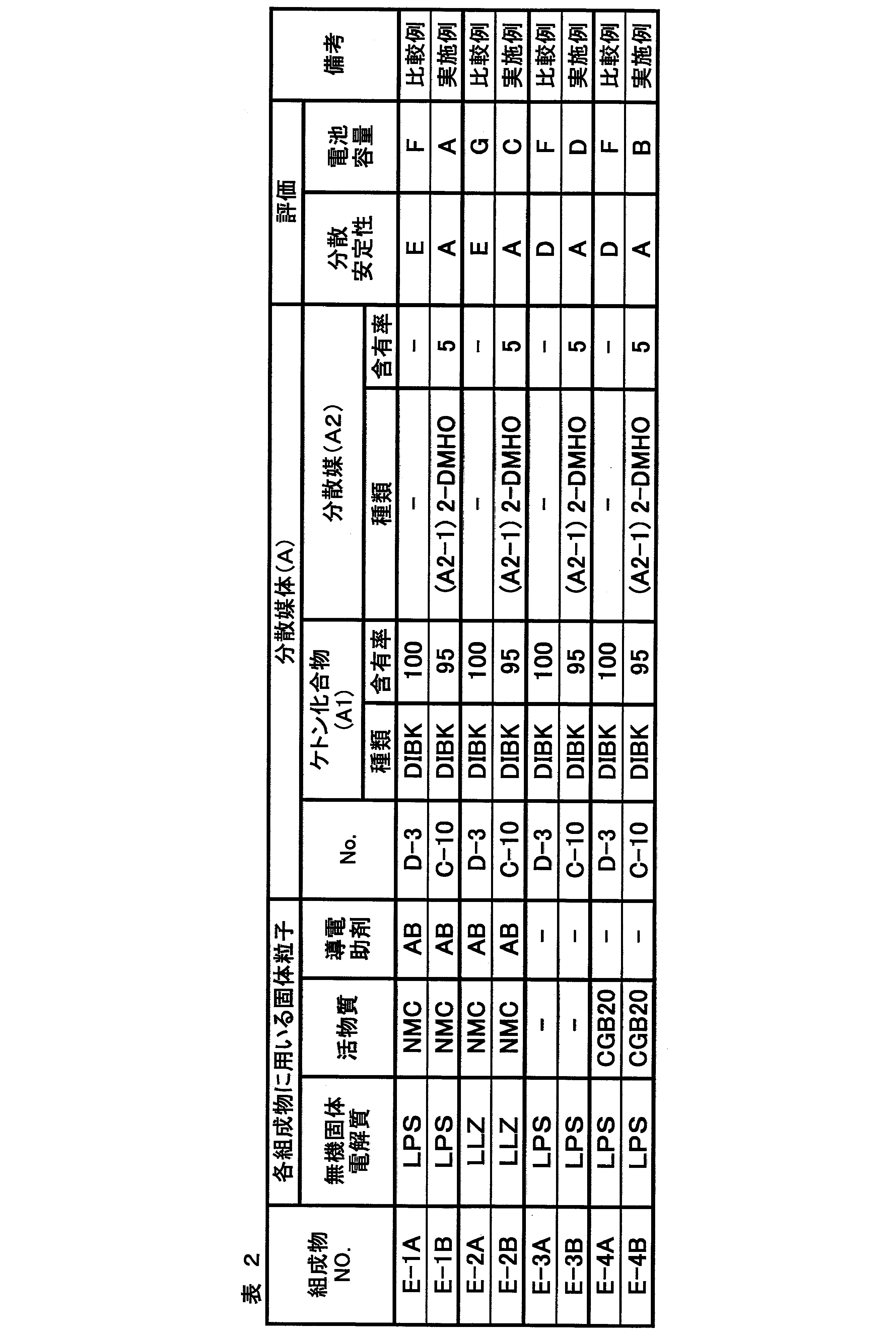
LPS:Li-P-S系ガラス(硫化物系無機固体電解質)
LLZ:Li7La3Zr2O12(酸化物系無機固体電解質)
CGB20:黒鉛(粒状)(負極活物質)
NMC:ニッケルマンガンコバルト酸リチウム(正極活物質)
AB:アセチレンブラック(導電助剤)
表2において、分散媒体(A)の番号は、実施例1においてこの分散媒体(A)を用いた正極用組成物の番号と同じである。例えば、分散媒体(A)欄中の「C-10」は、実施例1において、正極用組成物C-10に用いた分散媒体(A)を表す。分散媒体(A)欄の「含有率」の単位は質量%である。
その結果、表2から明らかなように、分散媒体D-3を用いると、固体電解質組成物(E-3A)、正極用組成物(E-1A、E-2A)及び負極用組成物(E-4A)のいずれにおいても、十分な分散安定性を示さないことがわかる。これに対して、本発明で規定する分散媒体(A)を用いると、固体電解質組成物(E-3B)、正極用組成物(E-1B、E-2B)及び負極用組成物(E-4B)のいずれにおいても、高い分散安定性を示す。
また、分散媒体D-3を含有する各組成物(E-1A~E-4A)を用いて製造した全固体二次電池は、いずれも、電池容量に劣る。これに対して、本発明で規定する分散媒体(A)を含有する各組成物(E-1B~E-4B)を用いて製造した全固体二次電池は、いずれも、更に高い電池容量を示す。
上記分散安定性及び電池容量の結果は、無機固体電解質として、硫化物系無機固体電解質を用いても酸化物系無機固体電解質を用いても同様であった(実施例2)。
実施例5は、正極用組成物、固体電解質組成物及び負極用組成物を同時重層塗布法により塗布して、アルミニウム箔、正極活物質層、固体電解質層及び負極活物質層からなる積層体と、この積層体を用いた全固体二次電池をそれぞれ製造して、得られた全固体二次電池の電池容量を測定した。本実施例では、正極活物質層、固体電解質層及び負極活物質層のすべての層を本発明の固体電解質組成物を用いて同時重層塗布法によって作製した態様についての電池容量の向上効果を確認した。その結果を表3に示す。
すなわち、実施例2及び3で調製した、上記正極用組成物E-1B、上記固体電解質組成物E-3B及び上記負極用組成物E-4Bをそれぞれ、アルミニウム支持体:A1N30-H(商品名、UACJ社製、厚み20μm、幅200mm)上に、アルミニウム支持体側から順に、正極活物質層の目付量が22mg/cm2、固体電解質層の目付量が6mg/cm2、負極活物質層の目付量が15mg/cm2となるように、スマートラボコーター(テクノスマート社製)を用いて同時重層塗布し、乾燥器中、150℃で3分乾燥した。これを20MPaで加圧した後に巻き取って、アルミニウム箔、正極活物質層、固体電解質層及び負極活物質層からなる積層体を作製した。
作製した積層体を直径10mmの円盤状に打ち抜き、内径10mmのポリエチレンテレフタレート(PET)製の円筒に入れた。円筒の両端開口部から直径10mmのステンレス鋼(SUS)製の棒を挿入して、積層体を350MPaの圧力で加圧形成し、50MPaの圧力をかけた状態で固定した。こうして、実施例5の全固体二次電池を製造した。
実施例6は、正極活物質層、固体電解質層及び負極活物質層を逐次重層法により形成して全固体二次電池を製造し、得られた全固体二次電池の電池容量を測定した。本実施例では、正極活物質層、固体電解質層及び負極活物質層のすべての層を本発明の固体電解質組成物を用いて逐次重層法により作製した態様についての電池容量の向上効果を確認した。その結果を表3に示す。
すなわち、実施例5において、同時重層塗布法に代えて逐次重層法により、正極用組成物、固体電解質組成物及び負極用組成物を用いて、正極活物質層、固体電解質層及び負極活物質層をそれぞれ形成した。具体的には、アルミニウム支持体:A1N30-H上に、正極用組成物E-1Bを塗布、乾燥して正極活物質層を形成し、次いで、この正極活物質層上に固体電解質組成物E-3Bを塗布、乾燥して固体電解質層を形成し、更にこの固体電解質組成物上に負極用組成物E-4Bを塗布、乾燥して負極活物質層を形成した。こうして、アルミニウム箔、正極活物質層、固体電解質層及び負極活物質層からなる積層体を作製した。各組成物の塗布条件は実施例5と同条件とした。こうして作製した積層体を用いたこと以外は、実施例5と同様にして、全固体二次電池を製造した。
製造した実施例5及び実施例6の各全固体二次電池を用いて、実施例1の<評価:電池容量の評価>のうち、充電電圧を3.6Vから4.2Vに、放電電圧を1.9Vから2.5Vに変更した以外は同様にして、電池容量を評価した。その結果を表3に示す。

2 負極活物質層
3 固体電解質層
4 正極活物質層
5 正極集電体
6 作動部位
10 全固体二次電池
Claims (23)
- 無機固体電解質と、分散媒体(A)とを含有する固体電解質組成物であって、
前記分散媒体(A)が、ケトン化合物(A1)と、前記ケトン化合物(A1)と異なる化学構造を有するケトン化合物(A2-1)、及びアルコール化合物(A2-2)から選択される少なくとも1種の分散媒(A2)とを含む固体電解質組成物。 - 活物質を含有する請求項1に記載の固体電解質組成物。
- 導電助剤を含有する請求項1又は2に記載の固体電解質組成物。
- 前記分散媒体(A)中の、前記分散媒(A2)の含有率が0質量%を超え、50質量%未満である、請求項1~3のいずれか1項に記載の固体電解質組成物。
- 前記ケトン化合物(A1)の炭素数が6以上であり、かつ前記ケトン化合物(A2-1)の炭素数が4以上である、請求項1~4のいずれか1項に記載の固体電解質組成物。
- 前記ケトン化合物(A2-1)の炭素数が6以上である、請求項1~5のいずれか1項に記載の固体電解質組成物。
- 前記ケトン化合物(A2-1)の炭素数が9以上である、請求項1~6のいずれか1項に記載の固体電解質組成物。
- 前記分散媒(A2)の少なくとも1種が、前記ケトン化合物(A1)の構造異性体である、請求項1~7のいずれか1項に記載の固体電解質組成物。
- 前記分散媒体(A)が、非極性分散媒を少なくとも1種含む、請求項1~8のいずれか1項に記載の固体電解質組成物。
- 前記活物質のメジアン径が、前記無機固体電解質のメジアン径よりも大きい、請求項1~9のいずれか1項に記載の固体電解質組成物。
- 請求項1~10のいずれか1項に記載の固体電解質組成物で構成した層を有する固体電解質含有シート。
- 分散媒体(A)中で無機固体電解質を分散する工程を有し、
前記分散媒体(A)が、ケトン化合物(A1)と、前記ケトン化合物(A1)と異なる化学構造を有するケトン化合物(A2-1)、及びアルコール化合物(A2-2)から選択される少なくとも1種の分散媒(A2)とを含む、
固体電解質組成物の製造方法。 - 前記分散媒体(A)中の、前記分散媒(A2)の含有率が0質量%を超え、50質量%未満である、請求項12に記載の固体電解質組成物の製造方法。
- 前記ケトン化合物(A1)の炭素数が6以上であり、かつ前記ケトン化合物(A2-1)の炭素数が4以上である、請求項12又は13に記載の固体電解質組成物の製造方法。
- 前記ケトン化合物(A2-1)の炭素数が6以上である、請求項12~14のいずれか1項に記載の固体電解質組成物の製造方法。
- 前記ケトン化合物(A2-1)の炭素数が9以上である、請求項12~15のいずれか1項に記載の固体電解質組成物の製造方法。
- 前記分散媒(A2)の少なくとも1種が、前記ケトン化合物(A1)の構造異性体である、請求項12~16のいずれか1項に記載の固体電解質組成物の製造方法。
- 前記分散媒体(A)が、非極性分散媒を少なくとも1種含む、請求項12~17のいずれか1項に記載の固体電解質組成物の製造方法。
- 前記分散する工程の後に、得られた予備分散物と、活物質とを混合する工程を有する、請求項12~18のいずれか1項に記載の固体電解質組成物の製造方法。
- 前記混合する工程が、前記予備分散物と、前記活物質と、導電助剤とを混合する工程である、請求項19に記載の固体電解質組成物の製造方法。
- 請求項12~20のいずれか1項に記載の固体電解質組成物の製造方法を介して、全固体二次電池用電極シートを製造する、全固体二次電池用電極シートの製造方法。
- 請求項12~20のいずれか1項に記載の固体電解質組成物の製造方法を介して、全固体二次電池を製造する、全固体二次電池の製造方法。
- 固体電解質組成物と、活物質を含有する固体電解質組成物とを同時重層塗布して、固体電解質層及び活物質層を形成する、請求項22に記載の全固体二次電池の製造方法であって、
前記固体電解質組成物及び前記活物質を含有する固体電解質組成物の少なくとも1つを、請求項12~20のいずれか1項に記載の固体電解質組成物の製造方法により製造する、全固体二次電池の製造方法。
Priority Applications (5)
| Application Number | Priority Date | Filing Date | Title |
|---|---|---|---|
| KR1020207020190A KR102425881B1 (ko) | 2018-02-05 | 2019-01-31 | 고체 전해질 조성물 및 그 제조 방법, 고체 전해질 함유 시트, 및 전고체 이차 전지용 전극 시트와 전고체 이차 전지의 제조 방법 |
| CN201980008197.4A CN111602272B (zh) | 2018-02-05 | 2019-01-31 | 固体电解质组合物及其制法、含固体电解质片材、全固态二次电池用电极片及该电池的制法 |
| EP19746751.7A EP3751642A4 (en) | 2018-02-05 | 2019-01-31 | SOLID ELECTROLYTE COMPOSITION AND METHOD OF PRODUCTION, SHEET CONTAINING A SOLID ELECTROLYTE, AND METHODS FOR MANUFACTURING SHEET OF ANY SOLID RECHARGEABLE BATTERY ELECTRODE AND ANY SOLID RECHARGEABLE BATTERY |
| JP2019569209A JP6928122B2 (ja) | 2018-02-05 | 2019-01-31 | 固体電解質組成物及びその製造方法、固体電解質含有シート、並びに、全固体二次電池用電極シート及び全固体二次電池の製造方法 |
| US16/935,182 US11605833B2 (en) | 2018-02-05 | 2020-07-21 | Solid electrolyte composition and method of manufacturing the same, solid electrolyte-containing sheet, electrode sheet for all-solid state secondary battery, and method of manufacturing all-solid state secondary battery |
Applications Claiming Priority (4)
| Application Number | Priority Date | Filing Date | Title |
|---|---|---|---|
| JP2018-018676 | 2018-02-05 | ||
| JP2018018676 | 2018-02-05 | ||
| JP2018-098992 | 2018-05-23 | ||
| JP2018098992 | 2018-05-23 |
Related Child Applications (1)
| Application Number | Title | Priority Date | Filing Date |
|---|---|---|---|
| US16/935,182 Continuation US11605833B2 (en) | 2018-02-05 | 2020-07-21 | Solid electrolyte composition and method of manufacturing the same, solid electrolyte-containing sheet, electrode sheet for all-solid state secondary battery, and method of manufacturing all-solid state secondary battery |
Publications (1)
| Publication Number | Publication Date |
|---|---|
| WO2019151373A1 true WO2019151373A1 (ja) | 2019-08-08 |
Family
ID=67478833
Family Applications (1)
| Application Number | Title | Priority Date | Filing Date |
|---|---|---|---|
| PCT/JP2019/003298 WO2019151373A1 (ja) | 2018-02-05 | 2019-01-31 | 固体電解質組成物及びその製造方法、固体電解質含有シート、並びに、全固体二次電池用電極シート及び全固体二次電池の製造方法 |
Country Status (6)
| Country | Link |
|---|---|
| US (1) | US11605833B2 (ja) |
| EP (1) | EP3751642A4 (ja) |
| JP (1) | JP6928122B2 (ja) |
| KR (1) | KR102425881B1 (ja) |
| CN (1) | CN111602272B (ja) |
| WO (1) | WO2019151373A1 (ja) |
Cited By (4)
| Publication number | Priority date | Publication date | Assignee | Title |
|---|---|---|---|---|
| JP2021099950A (ja) * | 2019-12-23 | 2021-07-01 | トヨタ自動車株式会社 | スラリー |
| WO2021131426A1 (ja) * | 2019-12-27 | 2021-07-01 | パナソニックIpマネジメント株式会社 | 固体電解質組成物、および、固体電解質粒子 |
| JP2022518316A (ja) * | 2019-05-15 | 2022-03-15 | エルジー エナジー ソリューション リミテッド | 全固体電池用電極及びそれを含む電極組立体の製造方法 |
| WO2023286512A1 (ja) * | 2021-07-16 | 2023-01-19 | パナソニックIpマネジメント株式会社 | 電池 |
Citations (19)
| Publication number | Priority date | Publication date | Assignee | Title |
|---|---|---|---|---|
| JPS6222066A (ja) | 1985-07-23 | 1987-01-30 | Wako Pure Chem Ind Ltd | ラテツクス凝集反応測定装置 |
| JPH026856A (ja) | 1988-06-27 | 1990-01-11 | Motonobu Shibata | 触媒担体およびその製造方法 |
| JPH0345473A (ja) | 1989-07-11 | 1991-02-27 | Toyoda Mach Works Ltd | 四輪操舵装置 |
| JPH0590844A (ja) | 1991-09-26 | 1993-04-09 | Toshiba Corp | 歪補償器 |
| JPH064516A (ja) | 1992-06-17 | 1994-01-14 | Toshiba Corp | 割当て決定支援方式 |
| JP2005271283A (ja) | 2004-03-23 | 2005-10-06 | Fuji Photo Film Co Ltd | 感熱記録材料の製造方法及び感熱記録材料 |
| JP2006247967A (ja) | 2005-03-09 | 2006-09-21 | Fuji Photo Film Co Ltd | インクジェット記録媒体、及びその製造方法 |
| JP2007083625A (ja) | 2005-09-22 | 2007-04-05 | Fujifilm Corp | インクジェット記録用媒体の製造方法 |
| JP2012212652A (ja) | 2011-03-18 | 2012-11-01 | Toyota Motor Corp | スラリー、固体電解質層の製造方法、電極活物質層の製造方法、および全固体電池の製造方法 |
| WO2013024724A1 (ja) * | 2011-08-12 | 2013-02-21 | 独立行政法人産業技術総合研究所 | リチウムイオン伝導性物質、該リチウムイオン伝導性物質を用いたリチウムイオン伝導性固体電解質、リチウムイオン電池の電極保護層、及び、該リチウムイオン伝導性物質の製造方法 |
| WO2014051032A1 (ja) | 2012-09-28 | 2014-04-03 | 日本ゼオン株式会社 | 全固体二次電池用スラリー、全固体二次電池用電極の製造方法、全固体二次電池用電解質層の製造方法及び全固体二次電池 |
| JP2015088486A (ja) | 2013-09-25 | 2015-05-07 | 富士フイルム株式会社 | 固体電解質組成物、これを用いた電池用電極シートおよび全固体二次電池 |
| JP2015088480A (ja) | 2013-09-25 | 2015-05-07 | 富士フイルム株式会社 | 固体電解質組成物および全固体二次電池用のバインダー、ならびにこれらを用いた電池用電極シートおよび全固体二次電池 |
| JP2016139511A (ja) | 2015-01-27 | 2016-08-04 | 富士フイルム株式会社 | 固体電解質組成物およびこれを用いた電池用電極シートならびに電池用電極シートおよび全固体二次電池の製造方法 |
| JP2016212990A (ja) * | 2015-04-30 | 2016-12-15 | 富士フイルム株式会社 | 全固体二次電池、電極活物質層用組成物および全固体二次電池用電極シートならびに全固体二次電池用電極シートおよび全固体二次電池の製造方法 |
| WO2017099248A1 (ja) * | 2015-12-11 | 2017-06-15 | 富士フイルム株式会社 | 固体電解質組成物、バインダー粒子、全固体二次電池用シート、全固体二次電池用電極シート及び全固体二次電池、並びに、これらの製造方法 |
| JP2018018676A (ja) | 2016-07-27 | 2018-02-01 | 大阪瓦斯株式会社 | 電気プラグ用の保護装置 |
| JP2018098992A (ja) | 2016-12-16 | 2018-06-21 | カルソニックカンセイ株式会社 | 電圧検出装置及び電圧検出方法 |
| JP2018152197A (ja) * | 2017-03-10 | 2018-09-27 | 東京電力ホールディングス株式会社 | 固体電解質及び固体電池 |
Family Cites Families (7)
| Publication number | Priority date | Publication date | Assignee | Title |
|---|---|---|---|---|
| JP2012199003A (ja) * | 2011-03-18 | 2012-10-18 | Toyota Motor Corp | スラリー、固体電解質層の製造方法および電極活物質層の製造方法 |
| WO2015001818A1 (ja) | 2013-07-04 | 2015-01-08 | 三井金属鉱業株式会社 | 結晶性固体電解質及びその製造方法 |
| CN107735887B (zh) | 2015-06-02 | 2021-01-01 | 富士胶片株式会社 | 正极用材料、全固态二次电池及其电极片以及所述电池和所述电极片的制造方法 |
| KR102019585B1 (ko) * | 2015-06-08 | 2019-09-06 | 후지필름 가부시키가이샤 | 고체 전해질 조성물, 전고체 이차 전지용 전극 시트 및 전고체 이차 전지와, 전고체 이차 전지용 전극 시트 및 전고체 이차 전지의 제조 방법 |
| CN106328992B (zh) * | 2015-06-30 | 2019-09-13 | 比亚迪股份有限公司 | 一种锂离子电池和该锂离子电池的制备方法 |
| WO2017104405A1 (ja) * | 2015-12-16 | 2017-06-22 | 富士フイルム株式会社 | 電極用材料、全固体二次電池用電極シートおよび全固体二次電池ならびに全固体二次電池用電極シートおよび全固体二次電池の製造方法 |
| JP6757573B2 (ja) * | 2016-02-29 | 2020-09-23 | Fdk株式会社 | 全固体電池の製造方法および全固体電池 |
-
2019
- 2019-01-31 WO PCT/JP2019/003298 patent/WO2019151373A1/ja unknown
- 2019-01-31 KR KR1020207020190A patent/KR102425881B1/ko active IP Right Grant
- 2019-01-31 JP JP2019569209A patent/JP6928122B2/ja active Active
- 2019-01-31 CN CN201980008197.4A patent/CN111602272B/zh active Active
- 2019-01-31 EP EP19746751.7A patent/EP3751642A4/en active Pending
-
2020
- 2020-07-21 US US16/935,182 patent/US11605833B2/en active Active
Patent Citations (19)
| Publication number | Priority date | Publication date | Assignee | Title |
|---|---|---|---|---|
| JPS6222066A (ja) | 1985-07-23 | 1987-01-30 | Wako Pure Chem Ind Ltd | ラテツクス凝集反応測定装置 |
| JPH026856A (ja) | 1988-06-27 | 1990-01-11 | Motonobu Shibata | 触媒担体およびその製造方法 |
| JPH0345473A (ja) | 1989-07-11 | 1991-02-27 | Toyoda Mach Works Ltd | 四輪操舵装置 |
| JPH0590844A (ja) | 1991-09-26 | 1993-04-09 | Toshiba Corp | 歪補償器 |
| JPH064516A (ja) | 1992-06-17 | 1994-01-14 | Toshiba Corp | 割当て決定支援方式 |
| JP2005271283A (ja) | 2004-03-23 | 2005-10-06 | Fuji Photo Film Co Ltd | 感熱記録材料の製造方法及び感熱記録材料 |
| JP2006247967A (ja) | 2005-03-09 | 2006-09-21 | Fuji Photo Film Co Ltd | インクジェット記録媒体、及びその製造方法 |
| JP2007083625A (ja) | 2005-09-22 | 2007-04-05 | Fujifilm Corp | インクジェット記録用媒体の製造方法 |
| JP2012212652A (ja) | 2011-03-18 | 2012-11-01 | Toyota Motor Corp | スラリー、固体電解質層の製造方法、電極活物質層の製造方法、および全固体電池の製造方法 |
| WO2013024724A1 (ja) * | 2011-08-12 | 2013-02-21 | 独立行政法人産業技術総合研究所 | リチウムイオン伝導性物質、該リチウムイオン伝導性物質を用いたリチウムイオン伝導性固体電解質、リチウムイオン電池の電極保護層、及び、該リチウムイオン伝導性物質の製造方法 |
| WO2014051032A1 (ja) | 2012-09-28 | 2014-04-03 | 日本ゼオン株式会社 | 全固体二次電池用スラリー、全固体二次電池用電極の製造方法、全固体二次電池用電解質層の製造方法及び全固体二次電池 |
| JP2015088486A (ja) | 2013-09-25 | 2015-05-07 | 富士フイルム株式会社 | 固体電解質組成物、これを用いた電池用電極シートおよび全固体二次電池 |
| JP2015088480A (ja) | 2013-09-25 | 2015-05-07 | 富士フイルム株式会社 | 固体電解質組成物および全固体二次電池用のバインダー、ならびにこれらを用いた電池用電極シートおよび全固体二次電池 |
| JP2016139511A (ja) | 2015-01-27 | 2016-08-04 | 富士フイルム株式会社 | 固体電解質組成物およびこれを用いた電池用電極シートならびに電池用電極シートおよび全固体二次電池の製造方法 |
| JP2016212990A (ja) * | 2015-04-30 | 2016-12-15 | 富士フイルム株式会社 | 全固体二次電池、電極活物質層用組成物および全固体二次電池用電極シートならびに全固体二次電池用電極シートおよび全固体二次電池の製造方法 |
| WO2017099248A1 (ja) * | 2015-12-11 | 2017-06-15 | 富士フイルム株式会社 | 固体電解質組成物、バインダー粒子、全固体二次電池用シート、全固体二次電池用電極シート及び全固体二次電池、並びに、これらの製造方法 |
| JP2018018676A (ja) | 2016-07-27 | 2018-02-01 | 大阪瓦斯株式会社 | 電気プラグ用の保護装置 |
| JP2018098992A (ja) | 2016-12-16 | 2018-06-21 | カルソニックカンセイ株式会社 | 電圧検出装置及び電圧検出方法 |
| JP2018152197A (ja) * | 2017-03-10 | 2018-09-27 | 東京電力ホールディングス株式会社 | 固体電解質及び固体電池 |
Non-Patent Citations (3)
| Title |
|---|
| A. HAYASHIS. HAMAH. MORIMOTOM. TATSUMISAGOT. MINAMI, CHEM. LETT., 2001, pages 872 - 873 |
| See also references of EP3751642A4 |
| T. OHTOMOA. HAYASHIM. TATSUMISAGOY. TSUCHIDAS. HAMAK. KAWAMOTO, JOURNAL OF POWER SOURCES, vol. 233, 2013, pages 231 - 235 |
Cited By (7)
| Publication number | Priority date | Publication date | Assignee | Title |
|---|---|---|---|---|
| JP2022518316A (ja) * | 2019-05-15 | 2022-03-15 | エルジー エナジー ソリューション リミテッド | 全固体電池用電極及びそれを含む電極組立体の製造方法 |
| JP7125548B2 (ja) | 2019-05-15 | 2022-08-24 | エルジー エナジー ソリューション リミテッド | 全固体電池用電極及びそれを含む電極組立体の製造方法 |
| US11811043B2 (en) | 2019-05-15 | 2023-11-07 | Lg Energy Solution, Ltd. | Electrode for all-solid-state battery and method for manufacturing electrode assembly comprising the same |
| JP2021099950A (ja) * | 2019-12-23 | 2021-07-01 | トヨタ自動車株式会社 | スラリー |
| JP7259733B2 (ja) | 2019-12-23 | 2023-04-18 | トヨタ自動車株式会社 | スラリー |
| WO2021131426A1 (ja) * | 2019-12-27 | 2021-07-01 | パナソニックIpマネジメント株式会社 | 固体電解質組成物、および、固体電解質粒子 |
| WO2023286512A1 (ja) * | 2021-07-16 | 2023-01-19 | パナソニックIpマネジメント株式会社 | 電池 |
Also Published As
| Publication number | Publication date |
|---|---|
| US20200350628A1 (en) | 2020-11-05 |
| KR102425881B1 (ko) | 2022-07-27 |
| EP3751642A1 (en) | 2020-12-16 |
| US11605833B2 (en) | 2023-03-14 |
| CN111602272A (zh) | 2020-08-28 |
| JPWO2019151373A1 (ja) | 2020-11-19 |
| KR20200096823A (ko) | 2020-08-13 |
| CN111602272B (zh) | 2023-07-07 |
| EP3751642A4 (en) | 2021-03-24 |
| JP6928122B2 (ja) | 2021-09-01 |
Similar Documents
| Publication | Publication Date | Title |
|---|---|---|
| JP6591687B2 (ja) | 固体電解質組成物、固体電解質含有シートおよび全固体二次電池ならびに固体電解質含有シートおよび全固体二次電池の製造方法 | |
| WO2018047946A1 (ja) | 電極層材、全固体二次電池電極用シートおよび全固体二次電池ならびに全固体二次電池用電極シートおよび全固体二次電池の製造方法 | |
| JP6893253B2 (ja) | 固体電解質組成物、固体電解質含有シート、全固体二次電池用電極シート及び全固体二次電池、並びに、固体電解質含有シート及び全固体二次電池の製造方法 | |
| US11605833B2 (en) | Solid electrolyte composition and method of manufacturing the same, solid electrolyte-containing sheet, electrode sheet for all-solid state secondary battery, and method of manufacturing all-solid state secondary battery | |
| JP6942810B2 (ja) | 固体電解質組成物、固体電解質含有シート及び全固体二次電池、並びに、固体電解質含有シート及び全固体二次電池の製造方法 | |
| JP6572063B2 (ja) | 全固体二次電池、全固体二次電池用電極シート及びこれらの製造方法 | |
| JP7064613B2 (ja) | 全固体二次電池用積層部材の製造方法及び全固体二次電池の製造方法 | |
| JP7059302B2 (ja) | 固体電解質組成物、固体電解質含有シート及び全固体二次電池、並びに、固体電解質含有シート及び全固体二次電池の製造方法 | |
| WO2018163976A1 (ja) | 固体電解質含有シート、固体電解質組成物および全固体二次電池、ならびに、固体電解質含有シートおよび全固体二次電池の製造方法 | |
| US11658282B2 (en) | Composition for forming active material layer and method for manufacturing the same, and methods for manufacturing electrode sheet for all-solid state secondary battery and all-solid state secondary battery | |
| WO2019203334A1 (ja) | 固体電解質組成物、全固体二次電池用シート、及び全固体二次電池、並びに、全固体二次電池用シート若しくは全固体二次電池の製造方法 | |
| JP7448657B2 (ja) | 全固体二次電池用シート及び全固体二次電池の製造方法、並びに、全固体二次電池用シート及び全固体二次電池 | |
| JP6673785B2 (ja) | 固体電解質組成物、固体電解質含有シートおよび全固体二次電池ならびに固体電解質含有シートおよび全固体二次電池の製造方法 | |
| JPWO2019098299A1 (ja) | 固体電解質組成物、固体電解質含有シート及び全固体二次電池並びに固体電解質含有シート及び全固体二次電池の製造方法 | |
| WO2022085733A1 (ja) | 電極組成物、全固体二次電池用電極シート及び全固体二次電池、並びに、全固体二次電池用電極シート及び全固体二次電池の製造方法 | |
| WO2022070850A1 (ja) | 無機固体電解質含有組成物、全固体二次電池用シート及び全固体二次電池、並びに、全固体二次電池用シート及び全固体二次電池の製造方法 |
Legal Events
| Date | Code | Title | Description |
|---|---|---|---|
| 121 | Ep: the epo has been informed by wipo that ep was designated in this application |
Ref document number: 19746751 Country of ref document: EP Kind code of ref document: A1 |
|
| ENP | Entry into the national phase |
Ref document number: 2019569209 Country of ref document: JP Kind code of ref document: A |
|
| ENP | Entry into the national phase |
Ref document number: 20207020190 Country of ref document: KR Kind code of ref document: A |
|
| NENP | Non-entry into the national phase |
Ref country code: DE |
|
| ENP | Entry into the national phase |
Ref document number: 2019746751 Country of ref document: EP Effective date: 20200907 |