WO2019142442A1 - コネクタ - Google Patents
コネクタ Download PDFInfo
- Publication number
- WO2019142442A1 WO2019142442A1 PCT/JP2018/040495 JP2018040495W WO2019142442A1 WO 2019142442 A1 WO2019142442 A1 WO 2019142442A1 JP 2018040495 W JP2018040495 W JP 2018040495W WO 2019142442 A1 WO2019142442 A1 WO 2019142442A1
- Authority
- WO
- WIPO (PCT)
- Prior art keywords
- terminal
- connection
- storage chamber
- housing
- housing main
- Prior art date
Links
Images


Classifications
-
- H—ELECTRICITY
- H01—ELECTRIC ELEMENTS
- H01R—ELECTRICALLY-CONDUCTIVE CONNECTIONS; STRUCTURAL ASSOCIATIONS OF A PLURALITY OF MUTUALLY-INSULATED ELECTRICAL CONNECTING ELEMENTS; COUPLING DEVICES; CURRENT COLLECTORS
- H01R13/00—Details of coupling devices of the kinds covered by groups H01R12/70 or H01R24/00 - H01R33/00
- H01R13/40—Securing contact members in or to a base or case; Insulating of contact members
- H01R13/42—Securing in a demountable manner
- H01R13/436—Securing a plurality of contact members by one locking piece or operation
- H01R13/4361—Insertion of locking piece perpendicular to direction of contact insertion
-
- H—ELECTRICITY
- H01—ELECTRIC ELEMENTS
- H01R—ELECTRICALLY-CONDUCTIVE CONNECTIONS; STRUCTURAL ASSOCIATIONS OF A PLURALITY OF MUTUALLY-INSULATED ELECTRICAL CONNECTING ELEMENTS; COUPLING DEVICES; CURRENT COLLECTORS
- H01R13/00—Details of coupling devices of the kinds covered by groups H01R12/70 or H01R24/00 - H01R33/00
- H01R13/40—Securing contact members in or to a base or case; Insulating of contact members
- H01R13/42—Securing in a demountable manner
- H01R13/424—Securing in base or case composed of a plurality of insulating parts having at least one resilient insulating part
-
- H—ELECTRICITY
- H01—ELECTRIC ELEMENTS
- H01R—ELECTRICALLY-CONDUCTIVE CONNECTIONS; STRUCTURAL ASSOCIATIONS OF A PLURALITY OF MUTUALLY-INSULATED ELECTRICAL CONNECTING ELEMENTS; COUPLING DEVICES; CURRENT COLLECTORS
- H01R13/00—Details of coupling devices of the kinds covered by groups H01R12/70 or H01R24/00 - H01R33/00
- H01R13/46—Bases; Cases
- H01R13/502—Bases; Cases composed of different pieces
- H01R13/506—Bases; Cases composed of different pieces assembled by snap action of the parts
-
- H—ELECTRICITY
- H01—ELECTRIC ELEMENTS
- H01R—ELECTRICALLY-CONDUCTIVE CONNECTIONS; STRUCTURAL ASSOCIATIONS OF A PLURALITY OF MUTUALLY-INSULATED ELECTRICAL CONNECTING ELEMENTS; COUPLING DEVICES; CURRENT COLLECTORS
- H01R13/00—Details of coupling devices of the kinds covered by groups H01R12/70 or H01R24/00 - H01R33/00
- H01R13/46—Bases; Cases
- H01R13/516—Means for holding or embracing insulating body, e.g. casing, hoods
- H01R13/518—Means for holding or embracing insulating body, e.g. casing, hoods for holding or embracing several coupling parts, e.g. frames
-
- H—ELECTRICITY
- H01—ELECTRIC ELEMENTS
- H01R—ELECTRICALLY-CONDUCTIVE CONNECTIONS; STRUCTURAL ASSOCIATIONS OF A PLURALITY OF MUTUALLY-INSULATED ELECTRICAL CONNECTING ELEMENTS; COUPLING DEVICES; CURRENT COLLECTORS
- H01R12/00—Structural associations of a plurality of mutually-insulated electrical connecting elements, specially adapted for printed circuits, e.g. printed circuit boards [PCB], flat or ribbon cables, or like generally planar structures, e.g. terminal strips, terminal blocks; Coupling devices specially adapted for printed circuits, flat or ribbon cables, or like generally planar structures; Terminals specially adapted for contact with, or insertion into, printed circuits, flat or ribbon cables, or like generally planar structures
- H01R12/70—Coupling devices
- H01R12/77—Coupling devices for flexible printed circuits, flat or ribbon cables or like structures
- H01R12/778—Coupling parts carrying sockets, clips or analogous counter-contacts
-
- H—ELECTRICITY
- H01—ELECTRIC ELEMENTS
- H01R—ELECTRICALLY-CONDUCTIVE CONNECTIONS; STRUCTURAL ASSOCIATIONS OF A PLURALITY OF MUTUALLY-INSULATED ELECTRICAL CONNECTING ELEMENTS; COUPLING DEVICES; CURRENT COLLECTORS
- H01R13/00—Details of coupling devices of the kinds covered by groups H01R12/70 or H01R24/00 - H01R33/00
- H01R13/46—Bases; Cases
- H01R13/514—Bases; Cases composed as a modular blocks or assembly, i.e. composed of co-operating parts provided with contact members or holding contact members between them
-
- H—ELECTRICITY
- H01—ELECTRIC ELEMENTS
- H01R—ELECTRICALLY-CONDUCTIVE CONNECTIONS; STRUCTURAL ASSOCIATIONS OF A PLURALITY OF MUTUALLY-INSULATED ELECTRICAL CONNECTING ELEMENTS; COUPLING DEVICES; CURRENT COLLECTORS
- H01R2201/00—Connectors or connections adapted for particular applications
- H01R2201/26—Connectors or connections adapted for particular applications for vehicles
Definitions
- the present invention relates to a connector used for a wire harness wired in a car or the like.
- a connector attached to a terminal of a wire harness has a plurality of connection terminals respectively provided to a plurality of wire terminals constituting the wire harness, and a plurality of terminal accommodation chambers for respectively accommodating and holding the plurality of connection terminals. It has a connector housing.
- the terminal accommodating chamber of the connector housing is formed in a cylindrical shape in which four sides are surrounded by the peripheral wall portion, a plurality of connection terminals provided on the wire end are inserted one by one into the terminal accommodating chamber when manufacturing the connector. Work is required, which causes the deterioration of workability.
- Patent Document 1 a plate-like housing in which a plurality of groove-like terminal storage chambers are juxtaposed is adopted, and A structure is proposed in which the workability is improved by inserting a plurality of connection terminals from the upper side into a plurality of grooved terminal storage chambers that are opened.
- the present invention has been made against the background described above, and the problem to be solved is that, even in the case where a groove-shaped terminal storage chamber opening upward is adopted, the housing of the connection terminal from the terminal storage chamber is removed. It is an object of the present invention to provide a connector having a novel structure which can be stably held without the size increase of the connector.
- the present invention provides a plate-like housing body, a groove-like terminal accommodating chamber opened in parallel on the upper surface of the housing body, and a terminal of a plurality of electric wires, which are respectively accommodated and arranged in the terminal accommodating chamber A plurality of connection terminals, and a cover portion which is overlapped on the upper surface of the housing main body and covers the terminal storage chamber, and the connection terminal is elastically deformed on the bottom surface of the terminal storage chamber. And a resilient locking claw projecting from the terminal receiving chamber to allow the connection terminal to be disengaged from the terminal receiving chamber by elastically returning to the terminal receiving chamber.
- a connector capable of stably holding the withdrawal of the connection terminal from the terminal accommodating chamber without increasing the size of the housing is provided. Provided.
- FIG. 10 is an exploded perspective view of the connector shown in FIG. 9;
- a plate-like housing main body a groove-like terminal receiving chamber opened in parallel on the upper surface of the housing main body, and a terminal of a plurality of electric wires.
- a plurality of connection terminals respectively accommodated and arranged in a chamber, and a cover portion overlaid on the upper surface of the housing main body to cover and cover the terminal accommodation chamber, and the bottom surface of the terminal accommodation chamber is elastic.
- An elastic lock claw is formed to allow insertion of the connection terminal into the terminal storage chamber by deformation and to engage with the connection terminal by elastic return to prevent the connection terminal from coming out of the terminal storage chamber. Connector.
- connection terminal inserted into the terminal storage chamber is permitted by elastic deformation on the bottom surface of the terminal storage chamber, and the connection terminal is engaged by the elastic return to prevent the connection terminal from coming out of the terminal storage chamber.
- Resilient locking claws are provided.
- the connection terminal inserted into the terminal storage chamber is stably prevented from coming off from the terminal storage chamber, so that the advantage of the groove-shaped terminal storage chamber opened in the upper surface of the housing main body and arranged in parallel is plural.
- connection terminal in the one described in the first aspect, is provided with a recess opening in a surface opposite to the bottom surface of the terminal receiving chamber.
- a pair of engaging protrusions protruding from each other in the longitudinal direction of the terminal receiving chamber are provided on the bottom surface of the terminal receiving chamber, and the pair of engaging protrusions serve as the contact terminals of the connection terminal.
- the connection terminals are received at the both sides in the longitudinal direction by being inserted and disposed in the recesses and the formation surfaces of the recesses of the pair of engagement projections and the connection terminals abut on both sides in the longitudinal direction. It is positioned and held with respect to the chamber.
- a pair of engaging projections that project to the bottom of the terminal accommodation chamber and are separated in the longitudinal direction are inserted into the recesses provided in the connection terminal, and the longitudinal direction
- the connection terminals By bringing the pair of engagement projections into contact at both sides, the connection terminals can be positioned and held on both sides in the longitudinal direction of the terminal accommodation chamber.
- movement of the terminal storage chamber to both sides in the longitudinal direction (front-back direction) is also regulated, and even the groove-shaped terminal storage chamber opened upward is connected
- the holding property of the terminal can be stably ensured.
- the pair of engagement projections are provided so as to protrude from the bottom surface of the terminal accommodation chamber, retention of the pitch between the connection terminals and avoidance of upsizing of the housing main body are also advantageously realized.
- At least one projecting end portion of the pair of engagement projections has an engagement claw projecting outward in the longitudinal direction.
- the elastic lock claw is configured to include the engagement protrusion and the engagement claw, and the upper surface of the engagement claw is a tapered surface that inclines downward as going outward. It is
- the elastic lock claw is provided to prevent the terminal accommodation chamber from being pulled upward by using the engagement protrusion that regulates the displacement in the front-rear direction in the terminal accommodation chamber of the connection terminal. It is possible to reduce the cost by further downsizing the connector and simplifying the configuration.
- the mating terminal is inserted into the distal end side in the longitudinal direction of the terminal accommodating chamber.
- the elastic lock claw is engaged with the inner surface of the connection portion of the connection terminal when the elastic lock claw is resiliently restored.
- the amount of penetration of the connection portion of the elastic lock claw into the inner surface is set in a range that does not interfere with the mating terminal.
- the elastic lock claw is inserted into the cylindrical connection portion of the connection terminal and engaged with the connection terminal, thereby preventing the connection terminal from being pulled upward.
- the connection portion of the existing connection terminal it is possible to configure the pull-out mechanism, and it is possible to further simplify the structure of the connector and to improve the versatility.
- the amount of intrusion of the elastic lock claw into the inner surface of the connection portion is set in a range that does not interfere with the other terminal, the connection stability of the connector can be stably maintained.
- a plurality of the housing bodies are stacked in a plurality of upper and lower stages, and are stacked on the lower housing body.
- the lower surface of the upper housing body to be engaged is combined with the upper surface of the lower housing body to form an intermediate cover portion that covers the terminal accommodation chamber, while the intermediate cover portion is configured
- the housing bodies are positioned and fixed to each other.
- the stacked connector by stacking the plurality of housing bodies in the upper and lower stages.
- the intermediate cover portion is configured by the lower surface of the housing main body to cover the terminal storage chamber, the height can be reduced compared to the conventional laminated connector.
- the cover portion and the housing main body are interlocked with each other by a locking mechanism provided on a side wall. It is
- the cover portion and the housing main body are mutually locked by the lock mechanism provided on the side wall, the overlapping state of the cover portion and the housing main body can be stably held. It becomes possible to hold the removal from the terminal storage chamber of the connection terminal more stably.
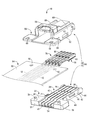
- FIGS. 1-8 A connector 10 according to a first embodiment of the invention is shown in FIGS. 1-8.
- the connector 10 is configured to include a plurality (five in the present embodiment) of electric wires 12 and a connector housing 14 provided at the end of the plurality of electric wires 12 as shown in FIGS. 1 to 3. . And it connects with the other party connector provided in the various electrical components which are not shown in figure from the front side (right side in FIG. 3) of the connector 10.
- the upper side means the upper side in FIGS. 1 and 2 and the lower side means the lower side in FIGS. 1 and 2 and the front means the right side and the rear side in FIG.
- the term “left” in FIG. 3 means “the left side in FIG. 3”
- “longitudinal direction” means the lateral direction in FIG. 3
- width direction means the vertical direction in FIG.
- the connector housing 14 is configured to include the housing main body 16 and the cover portion 18, and each of them is made of, for example, a synthetic resin such as polypropylene (PP) or polyamide (PA) by injection molding or the like. It is integrally formed.
- the housing body 16 is generally plate-shaped.
- a terminal housing portion 20 having a substantially horizontally elongated rectangular shape in plan view is provided on the front end side (right end side in FIG. 6) of the housing main body 16 in the longitudinal direction.
- a wire support portion 22 having a substantially vertically elongated rectangular shape in plan view is provided.
- the terminal accommodating portion 20 is opened in the length direction outward and the upper surface 24 of the housing main body 16 and extends in the longitudinal direction in a substantially rectangular cross-sectional shape and in the width direction (in FIG.
- a plurality of substantially groove-shaped terminal accommodating chambers 26 arranged in parallel with each other in the vertical direction) are provided.
- the central portion in the width direction of the substantially central portion in the longitudinal direction of the bottom surface 28 of the terminal accommodating chamber 26 is mutually separated in the longitudinal direction (lateral direction in FIG. 6) of the terminal accommodating chamber 26 and directed upward.
- a pair of substantially square columnar engaging projections 30, 30 are provided to project. Of the pair of engagement projections 30, 30 at the projecting end of the engagement projection 30 located on the front side (right side in FIG. 6), as shown in FIG.
- An engagement claw 32 projecting in a substantially triangular sectional shape is protruded toward the right).
- the elastic lock claw 34 is configured to include the engagement projection 30 and the engagement claw 32, and the taper is inclined downward as the upper surface 36 of the engagement claw 32 goes outward (right side in FIG. 8). It is considered to be a face.
- the protrusion height dimension of a pair of engagement protrusion 30 and 30 is formed lower on the front side than on the rear side, this will be described later, the core wire caulking portion 76 and the electric wire engaged with each other It is only formed corresponding to the height dimension from the bottom surface 28 of the terminal accommodating chamber 26 of the caulking portion 78.
- the width direction (in FIG. 6) is on the front side (right side in FIGS. 6 and 8) of the elastic lock claw 34 on the bottom surface 28 of the terminal accommodating chamber 26.
- an engagement projection 38 is formed which protrudes in a substantially rectangular shape in plan view.
- an engagement recess 40 opened to the bottom surface 28 of the terminal accommodating chamber 26 is formed (see FIGS. 6 and 8).
- FIGS. 2 and 5 to 6 the front end and the rear end of the side walls 42 and 42 in the width direction (vertical direction in FIG.
- a fitting protrusion 44 is provided which protrudes outward in a substantially rectangular cross-sectional shape and extends upward. Further, between the fitting projections 44 provided on the side walls 42, lock portions 46 which protrude outward and extend in a substantially trapezoidal cross-sectional shape in the longitudinal direction are formed.
- the upper surface 48 of the wire support 22 is connected to the rear end side opening 50 of the terminal accommodating chamber 26 and at the rear end 52 of the housing main body 16.
- a substantially groove-shaped wire housing groove 54 which opens and extends in a substantially rectangular cross-sectional shape in the length direction is opened on the upper surface 48 of the wire support portion 22 and arranged in parallel in the width direction (vertical direction in FIG. 6) It is done.
- positioning projections 56 are provided in a substantially cylindrical shape.
- the protruding tip of the positioning projection 56 is slightly tapered.
- a second positioning recess 100 described later is provided on the bottom surface of the wire support 22 at a position corresponding to the positioning protrusion 56.
- the cover portion 18 has a substantially block shape, and the upper portion of the cover portion 18 is used to release the engagement between the connector 10 and a mating connector (not shown).
- An engagement release portion 58 is provided.
- An engagement frame 62 is provided.
- fitting recesses 64 opened downward and on both sides in the width direction are provided.
- a sandwiching member which protrudes in a substantially rectangular flat shape toward the rear side (left side in FIG. 3) and extends toward both sides in the width direction (vertical direction in FIG. 3)
- the part 66 is provided on the rear end side of the cover portion 18.
- Through holes 68 penetrating in a substantially circular cross-sectional shape in the vertical direction are formed on both sides in the width direction of the rear end side of the sandwiching portion 66.
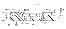
- connection terminals 70 are connected to the ends of the wires 12 respectively. More specifically, the insulation coating 72 on the tip end side (right side in FIG. 8) of the electric wire 12 is peeled off to expose the core wire 74, the core wire 74 is exposed to the core wire caulking portion 76 of the connection terminal 70, and the core wire 74 is exposed.
- the electric wire 12 is fixed and connected to the connection terminal 70 by caulking the tip end portion of the electric wire 12 in the electric wire caulking portion 78 of the connection terminal 70. Further, at the tip end portion (right side in FIG. 8) of the connection terminal 70, a cylindrical connection portion 80 opened in the length direction (left and right direction in FIG. 8) is formed. Then, as shown in FIG.
- connection terminal 70 in the connection terminal 70, a recess 82 opened in a surface opposite to the bottom surface 28 of the terminal accommodation chamber 26 between the core caulking portion 76 and the connection portion 80.
- an engaging portion 83 extending along the outer surface is formed at the lower rear end (the left end in FIG. 8) in FIG.
- an engaging portion 84 extending obliquely outward is formed.
- an elastic contact piece 86 which extends along the inner surface from the rear end portion (left end portion in FIG. 8) at the upper portion in FIG. There is.
- an embossed portion 88 is formed on the inner surface of the connection portion 80 by the inward end of the lower front end side (the right end side in FIG. 8) in FIG.
- the mating connector 89 is connected to the mating connector.
- the mating terminal 89 is described by a virtual line.
- the plurality of electric wires 12 extending from the connection terminal 70 are fixed to the sheet-like reinforcing member 90 in a state of being arranged in parallel.
- a positioning hole 92 having a substantially circular cross-sectional shape is penetrated on both sides in the width direction across the plurality of electric wires 12 on the front end side (right end side in FIG. 7) of the sheet-like reinforcing member 90.
- the electric wire 12 has a structure in which a core wire 74 obtained by bundling a plurality of copper, aluminum and other metal wires as conductors is covered with an insulating coating 72 having electrical insulation such as ethylene resin or styrene resin.
- the connection terminal 70 is integrally formed using various metal materials having conductivity and capable of being pressed or punched, such as brass, copper, copper alloy, aluminum, aluminum alloy, etc. .
- the sheet reinforcing member 90 for example, a glass fiber non-woven fabric, an aramid fiber non-woven fabric or the like impregnated with an epoxy resin or a phenol resin is used to press the sheet reinforcing member 90 against the electric wire 12 by heat press or the like. It is possible to fix by.
- the connector 10 thus configured is assembled as follows. First, the wire bundle with sheet-like reinforcing member 94 fixed to the sheet-like reinforcing member 90 is prepared in a state in which the plurality of electric wires 12 to which the connection terminals 70 are connected are connected in parallel. Then, the plurality of connection terminals 70 provided at the ends of the plurality of electric wires 12 in the sheet-like reinforcing member-attached wire bundle 94 are accommodated and arranged in the terminal accommodation chambers 26 provided in the housing main body 16, and A positioning hole 92 formed in the member 90 is fitted into the positioning projection 56 of the housing main body 16.
- the plurality of electric wires 12 extending from the rear end side opening 50 of the terminal accommodation chamber 26 is accommodated and held in the electric wire accommodation groove 54 provided in the electric wire support 22 and the front end of the sheet-like reinforcing member 90
- the side (right end side in FIG. 7) is placed on the upper surface 24 of the housing main body 16. More specifically, the connection terminal 70 is inserted from above into the terminal accommodating chamber 26 so that the pair of engagement projections 30, 30 are disposed in the recess 82.
- the elastic lock claw 34 formed of the engagement protrusion 30 having the engagement claw 32 positioned on the front side (right side in FIG. 8) is elastically deformed rearward to insert the connection terminal 70 into the terminal storage chamber 26.
- connection terminal 70 when the connection terminal 70 is placed in the terminal storage chamber 26, the elastic lock claw 34 elastically returns, and the engagement claw 32 of the elastic lock claw 34 enters the inner surface of the connection portion 80 of the connection terminal 70.
- the connection terminal 70 is advantageously prevented from coming out of the terminal accommodating chamber 26 (see FIG. 8).
- the pair of engagement projections 30, 30 are inserted into the recess 82 of the connection terminal 70, and the pair of engagement projections 30, 30 and the recess 82 are formed on both sides in the longitudinal direction (left and right direction in FIG. 8).
- connection terminals 70 are positioned and held on both sides in the longitudinal direction.
- the cylindrical connection portion 80 of the connection terminal 70 into which the mating terminal 89 is inserted is disposed on the tip end side (right side in FIG. 8) of the terminal accommodation chamber 26 in the longitudinal direction.
- the elastic lock claw 34 is elastically returned and the engagement claw 32 of the elastic lock claw 34 is engaged with the inner surface of the connection portion 80 of the connection terminal 70, the elastic lock claw 34 is engaged.
- the amount of penetration of the connecting portion 80 into the inner surface of the connecting portion 80 is set in a range that does not interfere with the mating terminal 89.
- the cover portion 18 is superimposed on the upper surface 24 of the housing main body 16 from above, and the positioning projection 56 provided on the housing main body 16 is press-fit into the through hole 68 of the cover portion 18.
- the terminal accommodating chamber 26 of the housing main body 16 is covered by the cover portion 18, and the front end portion of the sheet-like reinforcing member 90 of the sheet-like reinforcing member attached wire bundle 94 covers the wire support portion 22 of the housing main body 16 and the cover It is held between the holding portions 66 of the portion 18.
- a first positioning recess in which the positioning protrusion 56 of the housing main body 16 is fitted is formed in the lower surface of the cover portion 18 by the through hole 68 of the cover portion 18.
- the lock portion 46 constituting the lock mechanism provided in the side wall 42 of the housing main body 16 engages with the through hole 61 of the engagement frame 62 constituting the lock mechanism provided in the side wall 60 of the cover portion 18 It is united. That is, the cover portion 18 and the housing main body 16 are interlocked with each other by the lock mechanisms 62 and 46 provided on the side walls 60 and 42, respectively.
- the fitting protrusion 44 provided on the side wall 42 of the housing main body 16 is fitted into the fitting recess 64 of the engagement frame 62 provided on the side wall 60 of the cover portion 18.
- the overlapping state of the cover portion 18 and the housing main body 16 can be stably held, and the sheet-like reinforcing member 90 can be held by the wire supporting portion 22 of the housing main body 16 and the holding portion 66 of the cover portion 18 It is possible to hold it more stably.
- the terminal accommodating chamber can be provided simply by inserting and arranging the connection terminals 70 connected to the terminals of the plurality of electric wires 12 from above with respect to the terminal accommodating chamber 26 of the housing main body 16
- the elastic lock claw 34 provided on the bottom surface 28 of the elastic member 26 elastically deforms to allow insertion of the connection terminal 70 into the terminal accommodating chamber 26 and elastically returns to engage with the connection portion 80 of the connection terminal 70. It is prevented from coming out of the terminal accommodating chamber 26.
- the connection terminals 70 provided at the ends of the plurality of wires 12 of the sheet-like reinforcing member-attached wire bundle 94 can be collectively fitted into the plurality of terminal accommodation chambers 26 from above and stably held. can do. Therefore, it is possible to prevent the shift and the drop of the connection terminal 70 at the time of the assembling operation, and to improve the assembling workability and the handling, and to improve the reliability of the connector 10 and the like.
- the elastic lock claws 34 are formed on the bottom surface 28 of the terminal accommodating chamber 26 and not provided on the side surface of the terminal accommodating chamber 26, enlargement of the housing main body 16 due to widening of the terminal accommodating chamber 26 is prevented. ing.
- the detachment prevention mechanism is configured by using the connection portion 80 of the existing connection terminal 70, the connector 10 can be further simplified and the versatility can be improved.
- the amount of penetration of the elastic lock claw 34 into the inner surface of the connection portion 80 is set in a range that does not interfere with the mating terminal 89, the connection stability of the connector 10 is stably maintained.
- connection terminal 70 is positioned and held with respect to the terminal accommodating chamber 26.
- the terminal accommodation chamber 26 is a substantially groove-shaped opening that opens upward Also, the connection terminal 70 can be stably held.
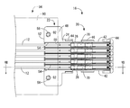
- the housing main body 16 is only one stage, but the housing main bodies 98 and 16 are the same as the connector 96 according to the second embodiment of the present invention shown in FIGS. It may be laminated and constituted up and down. More specifically, as shown in FIGS. 9 to 10, the lower surface of the upper housing main body 98 in which the housing main bodies 98 and 16 are stacked in two upper and lower stages and is superimposed on the lower housing main body 16 Is superimposed on the upper surface 24 of the lower housing body 16 to cover the terminal accommodating chamber 26 of the housing body 16.
- an intermediate cover portion for sandwiching the sheet-like reinforcing member 90 with the wire support portion 22 of the housing main body 16 is constituted by the housing main body 98
- the lower housing main body 16 is provided in the intermediate cover portion.
- a second positioning recess 100 is provided in which the positioning protrusion 56 provided to project from the wire support 22 in the second embodiment is fitted (see FIG. 10). Then, by press-fitting the positioning projection 56 into the second positioning recess 100, the housing main bodies 98 and 16 stacked one on top of the other are positioned and fixed.
- the housing main body 98 disposed between the cover portion 18 and the lowermost housing main body 16 has an engagement frame 62 constituting a lock mechanism in comparison with the lowermost housing main body 16.
- the housing body 16,98 are the same shape. Therefore, it is possible to reduce the mold cost and manufacture the housing body 16,98. Further, when the lock mechanism is not provided, only the housing main body 16 can be used, so that the configuration can be further simplified and the parts management can be facilitated.
- the housing bodies 98 and 16 are stacked in two upper and lower stages, but the number of stages to be stacked can be easily increased by increasing the number of stacked housing bodies 98. be able to.
- the fitting of the positioning protrusion 56 to the through hole 68 and the second positioning recess 100 that constitute the first positioning recess is performed by pressing, but may be inserted, and the sheet in that case
- the sandwiching of the reinforcing member 90 may be constituted by a lock mechanism such as the lock mechanisms 46 and 62, for example.
- the first positioning recess may be the through hole 68 as in the first embodiment, or may be a recess such as the second positioning recess 100.
- the combination of the convex portion and the concave portion in the positioning protrusion 56 and the through hole 68 constituting the first positioning concave portion and the second positioning concave portion 100 may be a combination of the concave portion and the convex portion. That is, the positioning projection 56 may be provided on the side of the cover body 18 or the housing main body 98 which is an intermediate cover part, and a recess may be formed on the upper surface 24 of the housing main bodies 16 and 98.
- the sheet-like reinforcing member 90 is not limited to the illustrated one, and an adhesive layer is provided on a resin-made sheet material so that the electric wire 12 is fixed, or a wire 12 for a cloth-made sheet material. Any material can be adopted as long as it can fix and hold the electric wire 12 in a sheet shape, such as a material fixed by sawing.
- the present invention has been described above, it goes without saying that the present invention is equally applicable to a connector having a structure that does not require such a sheet-like reinforcing member 90.
Landscapes
- Connector Housings Or Holding Contact Members (AREA)
Priority Applications (3)
| Application Number | Priority Date | Filing Date | Title |
|---|---|---|---|
| US16/960,409 US11171437B2 (en) | 2018-01-22 | 2018-10-31 | Connector |
| DE112018006917.6T DE112018006917T5 (de) | 2018-01-22 | 2018-10-31 | Verbinder |
| CN201880087226.6A CN111684666B (zh) | 2018-01-22 | 2018-10-31 | 连接器 |
Applications Claiming Priority (2)
| Application Number | Priority Date | Filing Date | Title |
|---|---|---|---|
| JP2018007954A JP6669997B2 (ja) | 2018-01-22 | 2018-01-22 | コネクタ |
| JP2018-007954 | 2018-01-22 |
Publications (1)
| Publication Number | Publication Date |
|---|---|
| WO2019142442A1 true WO2019142442A1 (ja) | 2019-07-25 |
Family
ID=67301344
Family Applications (1)
| Application Number | Title | Priority Date | Filing Date |
|---|---|---|---|
| PCT/JP2018/040495 WO2019142442A1 (ja) | 2018-01-22 | 2018-10-31 | コネクタ |
Country Status (5)
| Country | Link |
|---|---|
| US (1) | US11171437B2 (zh) |
| JP (1) | JP6669997B2 (zh) |
| CN (1) | CN111684666B (zh) |
| DE (1) | DE112018006917T5 (zh) |
| WO (1) | WO2019142442A1 (zh) |
Families Citing this family (4)
| Publication number | Priority date | Publication date | Assignee | Title |
|---|---|---|---|---|
| JP6669996B2 (ja) * | 2018-01-22 | 2020-03-18 | 株式会社オートネットワーク技術研究所 | コネクタ |
| JP7379115B2 (ja) * | 2019-11-26 | 2023-11-14 | キヤノン株式会社 | 撮像装置 |
| US11271339B2 (en) * | 2020-04-03 | 2022-03-08 | Tyco Electronics Amp Korea Co., Ltd. | Connector assembly and method of manufacturing the same |
| US11855374B2 (en) * | 2021-06-04 | 2023-12-26 | Te Connectivity Solutions Gmbh | Housing and connector for a flat flexible cable |
Citations (4)
| Publication number | Priority date | Publication date | Assignee | Title |
|---|---|---|---|---|
| WO2009148027A1 (ja) * | 2008-06-02 | 2009-12-10 | 三菱電線工業株式会社 | 電気コネクタ |
| JP2011134580A (ja) * | 2009-12-24 | 2011-07-07 | Yazaki Corp | コネクタ |
| JP2011134571A (ja) * | 2009-12-24 | 2011-07-07 | Autonetworks Technologies Ltd | 積層式コネクタ |
| JP2017010759A (ja) * | 2015-06-22 | 2017-01-12 | 株式会社オートネットワーク技術研究所 | ジョイントコネクタ |
Family Cites Families (9)
| Publication number | Priority date | Publication date | Assignee | Title |
|---|---|---|---|---|
| JP2001102122A (ja) * | 1999-09-30 | 2001-04-13 | Fuji Heavy Ind Ltd | 多極コネクタ |
| JP2001230038A (ja) * | 2000-02-15 | 2001-08-24 | Yazaki Corp | 積層プレートコネクタの製造方法 |
| JP3854457B2 (ja) * | 2000-10-18 | 2006-12-06 | 矢崎総業株式会社 | プレート状絶縁体と、該プレート状絶縁体への電線の固定方法 |
| JP3960943B2 (ja) * | 2003-05-08 | 2007-08-15 | 古河電気工業株式会社 | ジョイントコネクタ |
| JP4534979B2 (ja) * | 2005-12-21 | 2010-09-01 | 住友電装株式会社 | 積層式コネクタ |
| JP5472679B2 (ja) | 2009-04-07 | 2014-04-16 | 住友電装株式会社 | コネクタ |
| JP5724836B2 (ja) * | 2011-11-09 | 2015-05-27 | 住友電装株式会社 | コネクタ |
| JP2015207511A (ja) * | 2014-04-23 | 2015-11-19 | 住友電装株式会社 | コネクタ |
| JP6249998B2 (ja) * | 2015-07-06 | 2017-12-20 | 矢崎総業株式会社 | コネクタ |
-
2018
- 2018-01-22 JP JP2018007954A patent/JP6669997B2/ja active Active
- 2018-10-31 CN CN201880087226.6A patent/CN111684666B/zh active Active
- 2018-10-31 WO PCT/JP2018/040495 patent/WO2019142442A1/ja active Application Filing
- 2018-10-31 US US16/960,409 patent/US11171437B2/en active Active
- 2018-10-31 DE DE112018006917.6T patent/DE112018006917T5/de active Pending
Patent Citations (4)
| Publication number | Priority date | Publication date | Assignee | Title |
|---|---|---|---|---|
| WO2009148027A1 (ja) * | 2008-06-02 | 2009-12-10 | 三菱電線工業株式会社 | 電気コネクタ |
| JP2011134580A (ja) * | 2009-12-24 | 2011-07-07 | Yazaki Corp | コネクタ |
| JP2011134571A (ja) * | 2009-12-24 | 2011-07-07 | Autonetworks Technologies Ltd | 積層式コネクタ |
| JP2017010759A (ja) * | 2015-06-22 | 2017-01-12 | 株式会社オートネットワーク技術研究所 | ジョイントコネクタ |
Also Published As
| Publication number | Publication date |
|---|---|
| CN111684666A (zh) | 2020-09-18 |
| US11171437B2 (en) | 2021-11-09 |
| JP6669997B2 (ja) | 2020-03-18 |
| CN111684666B (zh) | 2022-07-15 |
| DE112018006917T5 (de) | 2020-10-01 |
| US20200335898A1 (en) | 2020-10-22 |
| JP2019128997A (ja) | 2019-08-01 |
Similar Documents
| Publication | Publication Date | Title |
|---|---|---|
| WO2019142442A1 (ja) | コネクタ | |
| JP5812429B2 (ja) | 電気接続箱 | |
| JP3652610B2 (ja) | コネクタ | |
| WO2009148027A1 (ja) | 電気コネクタ | |
| JP2019128997A5 (zh) | ||
| WO2019142422A1 (ja) | コネクタ | |
| JP5414836B2 (ja) | コネクタ | |
| JP2019128996A5 (zh) | ||
| JP4762966B2 (ja) | メスコネクタ | |
| JP6955228B2 (ja) | コネクタ | |
| JP2013093226A (ja) | ジョイントコネクタ | |
| JP6974805B2 (ja) | コネクタ | |
| JP5381602B2 (ja) | 積層式コネクタ | |
| JP7042580B2 (ja) | コネクタ、ハウジング、カバー体、及びコネクタ付ワイヤーハーネス | |
| US6443782B1 (en) | Joint connector | |
| JP5691803B2 (ja) | コネクタおよび電気接続箱 | |
| JP3989386B2 (ja) | ジョイントコネクタ | |
| JP5107004B2 (ja) | 合体コネクタ | |
| WO2023042619A1 (ja) | 積層コネクタ | |
| JP4134236B1 (ja) | 電気コネクタ | |
| JP2023176139A (ja) | 積層コネクタ | |
| WO2019167617A1 (ja) | コネクタ | |
| JP2021163533A (ja) | コネクタ | |
| JP2024010465A (ja) | コネクタホルダ | |
| JP2003017177A (ja) | コネクタ |
Legal Events
| Date | Code | Title | Description |
|---|---|---|---|
| 121 | Ep: the epo has been informed by wipo that ep was designated in this application |
Ref document number: 18900926 Country of ref document: EP Kind code of ref document: A1 |
|
| DPE1 | Request for preliminary examination filed after expiration of 19th month from priority date (pct application filed from 20040101) | ||
| 122 | Ep: pct application non-entry in european phase |
Ref document number: 18900926 Country of ref document: EP Kind code of ref document: A1 |