WO2019130738A1 - 印刷装置、転写ローラ - Google Patents
印刷装置、転写ローラ Download PDFInfo
- Publication number
- WO2019130738A1 WO2019130738A1 PCT/JP2018/038504 JP2018038504W WO2019130738A1 WO 2019130738 A1 WO2019130738 A1 WO 2019130738A1 JP 2018038504 W JP2018038504 W JP 2018038504W WO 2019130738 A1 WO2019130738 A1 WO 2019130738A1
- Authority
- WO
- WIPO (PCT)
- Prior art keywords
- blanket
- plate
- transfer roller
- intaglio
- printing apparatus
- Prior art date
- Legal status (The legal status is an assumption and is not a legal conclusion. Google has not performed a legal analysis and makes no representation as to the accuracy of the status listed.)
- Ceased
Links
Images



Classifications
-
- B—PERFORMING OPERATIONS; TRANSPORTING
- B41—PRINTING; LINING MACHINES; TYPEWRITERS; STAMPS
- B41F—PRINTING MACHINES OR PRESSES
- B41F17/00—Printing apparatus or machines of special types or for particular purposes, not otherwise provided for
- B41F17/08—Printing apparatus or machines of special types or for particular purposes, not otherwise provided for for printing on filamentary or elongated articles, or on articles with cylindrical surfaces
-
- B—PERFORMING OPERATIONS; TRANSPORTING
- B41—PRINTING; LINING MACHINES; TYPEWRITERS; STAMPS
- B41F—PRINTING MACHINES OR PRESSES
- B41F17/00—Printing apparatus or machines of special types or for particular purposes, not otherwise provided for
- B41F17/08—Printing apparatus or machines of special types or for particular purposes, not otherwise provided for for printing on filamentary or elongated articles, or on articles with cylindrical surfaces
- B41F17/14—Printing apparatus or machines of special types or for particular purposes, not otherwise provided for for printing on filamentary or elongated articles, or on articles with cylindrical surfaces on articles of finite length
-
- B—PERFORMING OPERATIONS; TRANSPORTING
- B41—PRINTING; LINING MACHINES; TYPEWRITERS; STAMPS
- B41F—PRINTING MACHINES OR PRESSES
- B41F3/00—Cylinder presses, i.e. presses essentially comprising at least one cylinder co-operating with at least one flat type-bed
- B41F3/18—Cylinder presses, i.e. presses essentially comprising at least one cylinder co-operating with at least one flat type-bed of special construction or for particular purposes
- B41F3/20—Cylinder presses, i.e. presses essentially comprising at least one cylinder co-operating with at least one flat type-bed of special construction or for particular purposes with fixed type-beds and travelling impression cylinders
-
- B—PERFORMING OPERATIONS; TRANSPORTING
- B41—PRINTING; LINING MACHINES; TYPEWRITERS; STAMPS
- B41N—PRINTING PLATES OR FOILS; MATERIALS FOR SURFACES USED IN PRINTING MACHINES FOR PRINTING, INKING, DAMPING, OR THE LIKE; PREPARING SUCH SURFACES FOR USE AND CONSERVING THEM
- B41N10/00—Blankets or like coverings; Coverings for wipers for intaglio printing
Definitions
- the present invention relates to an offset printing technique using a transfer roller.
- Patent Document 1 describes a printing apparatus using a transfer pad made of silicone rubber or the like.
- This printing apparatus prints a transfer material on a transfer-receiving material by pressing a transfer pad to which a transfer material of a predetermined pattern has previously attached to the transfer-receiving material.
- the regulating member is disposed adjacent to the transfer pad, and the deformation of the transfer pad pressed against the transfer target to the outside is regulated by the regulating member, whereby the transfer pad is transferred Keep it in close contact with your body.
- the present invention has been made in view of the above problems, and when printing is performed using a transfer roller provided with a restricting member that restricts deformation of the blanket in the axial direction, the plate and the plate are received when ink is received from the plate to the blanket.
- An object of the present invention is to suppress interference with a restricting member.
- the printing apparatus has a stage for supporting a plate on which a pattern is formed, and a blanket on the outer peripheral surface, and the blanket moves relative to the plate while rotating while in contact with the plate.
- the transfer roller has a restriction member on the end face of the blanket, which is a surface orthogonal to the rotational axis direction of the transfer roller, and the transfer roller deforms the blanket in the rotational axis direction. In the state where the blanket contacts the plate, the blanket protrudes from the regulating member in the direction of the plate to form a gap between the regulating member and the plate.
- the transfer roller according to the present invention is disposed on the axial center, the blanket provided on the outer peripheral surface of the axial center, and the end face of the blanket which is a plane orthogonal to the axial direction of the axial center And the blanket is rotated in contact with the plate, and moves relative to the plate while receiving ink from the plate onto the blanket, with the blanket contacting the plate
- the blanket protrudes from the regulating member in the direction of the plate to form a gap between the regulating member and the plate.
- the blanket protrudes in the direction of the plate from the regulating member in a state where the blanket is in contact with the plate for receiving ink from the plate to the blanket.
- a gap is formed between the member and the plate. Therefore, when the ink is received from the plate to the blanket, the interference between the plate and the regulating member can be suppressed.
- the printing apparatus is configured such that the blanket has a cylindrical shape of radius R1 and the restricting member has a disc shape of radius R2 shorter than the radius R1 and the blanket and the restricting member are coaxially arranged. Also good.
- the blanket has a radius R1 that is longer than the radius R2 of the regulating member.
- the printing apparatus may be configured such that the distance L between the rotation shaft of the transfer roller and the plate is shorter than the radius R1 and the radius R2 is shorter than the distance L when the blanket contacts the plate.
- the blanket is pressed against the plate by the difference between the radius R1 and the distance L, and it is possible to reliably receive the ink from the plate to the blanket.
- the radius R2 is smaller than the distance L, interference between the plate and the restricting member can be suppressed when the ink is received from the plate to the blanket.
- the print object is pushed into the blanket.
- the restriction member may configure the printing apparatus such that it is separated from the blanket in the rotational axis direction. In such a configuration, after the blanket is separated from the print object, the shape of the blanket can be reliably returned.
- the printing apparatus may be configured such that the distance between the regulating member and the blanket in the rotational axis direction is variable. In such a configuration, it is possible to appropriately change the distance between the blanket and the regulating member to the extent that the regulation of the deformation of the blanket by the regulating member is not impaired.
- the transfer roller further includes a spacer that defines the distance between the control member and the blanket
- the printing apparatus can be configured so that the distance between the control member and the blanket can be changed by changing the thickness of the spacer. good.
- the distance between the regulating member and the blanket can be changed by a simple operation such as changing the thickness of the spacer.
- the printing apparatus may be configured such that the restriction members are disposed on both sides of the end face of the blanket.
- the restriction members are disposed on both sides of the end face of the blanket.
- the plate and the regulating member are used when receiving ink from the plate to the blanket It is possible to make it possible to suppress the interference of
- FIG. 1 is a perspective view showing the configuration of an embodiment of a printing apparatus according to the present invention.
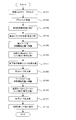
- 5 is a flowchart showing the flow of processing in the printing operation.
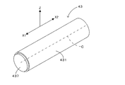
- FIG. 2 is a perspective view schematically showing a transfer roller used in the printing apparatus of FIG. 1.
- FIG. 4 is an exploded perspective view schematically showing the transfer roller of FIG. 3 in an exploded manner.
- FIG. 4 is a side view schematically showing the transfer roller of FIG. 3;
- FIG. 4 is a side view schematically showing the transfer roller of FIG. 3;
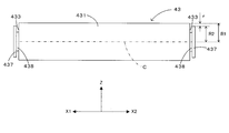
- FIG. 10 is a side view schematically showing a modification of the transfer roller.
- FIG. 1 is a perspective view showing the configuration of an embodiment of a printing apparatus according to the present invention.
- the printing apparatus 1 is an apparatus for forming a pattern on the surface of a work having a three-dimensional shape according to the principle of intaglio printing. More specifically, the printing apparatus 1 fills the ink into the intaglio plate in which the concave portion corresponding to the pattern is formed on the surface of the flat substrate, and transfers the ink to the work through the transfer roller, An ink pattern is formed on the work surface.
- the printing apparatus 1 mainly includes a base 2, a plate stage unit 10, a plate alignment unit 20, ink filling units 30, 50, a roller unit 40, a work alignment unit 60, and a work stage unit 70. , A transport unit 80 for moving the printing plate stage unit 10 and the work stage unit 70, and a control unit 90.
- the control unit 90 controls each part of the printing apparatus 1 according to a program installed in advance to fill the concave portions provided in the flat plate-like intaglio P with ink; A receiving process for receiving the P ink and a transferring process for transferring the received ink to the three-dimensional workpiece W are performed. Thereby, the pattern defined by the concave portion of the intaglio P is printed on the work W.
- the intaglio P has a pattern area Pa and a margin area Pb surrounding the pattern area Pa. A recess serving as a pattern is provided in the pattern area Pa, while the margin Pb has a flat shape.
- an XYZ orthogonal coordinate system is appropriately shown in order to clarify the arrangement relationship of each part of the apparatus.
- the XY plane is a horizontal plane
- the longitudinal direction of the printing apparatus 1 in the horizontal direction is a “Y direction”.
- the direction toward the printing plate stage unit 10 in the conveyance direction Y of the conveyance unit 80 is referred to as “Y1”, and the direction toward the work stage unit 70 is referred to as “Y2”.
- a horizontal direction orthogonal to the Y direction is referred to as "X direction”.
- the direction toward the front of the device is referred to as “X1” and the direction toward the back of the device is referred to as “X2”.
- the vertical direction is referred to as "Z direction”.
- the base 2 is extended in the Y direction as shown in FIG.
- a pair of linear motion guides 81, 81, a linear motion drive unit 82 such as a linear motor disposed between the linear motion guides 81, and a linear scale (not shown) extend in the Y direction on the upper surface of the base 2 It is done.
- the two linear transfer guides 83 and 84 are provided in the linear movement guide 81 and the linear movement drive unit 82, and move linearly in the Y direction in response to the drive of the linear movement drive unit 82.
- the plate stage unit 10 is mounted on the transfer stage 83 on one side of the two transfer stages 83 and 84, and the work stage unit 70 is mounted on the transfer stage 84 on the other side.
- the printing plate stage unit 10 and the work stage unit 70 can be reciprocated in the Y direction independently of each other.
- the plate stage unit 10 has a support 11 disposed on the upper surface of the transfer stage 83, and a plate stage 12 attached to the upper surface of the support 11 and holding the intaglio P on its upper surface.
- the linear drive unit 82 moves the transport stage 83 in the Y direction according to the operation command from the control unit 90, so that it is possible to transport the intaglio P held by the plate stage 12 in the Y direction. .
- the work stage unit 70 is provided with a position adjustment mechanism 71 disposed on the upper surface of the transfer stage 84, a work stage 72 attached to the upper surface of the position adjustment mechanism 71 and holding the workpiece W on the upper surface, and two reference masks (Calibration member)
- a calibration unit 73 composed of 731 and 732 is provided.
- the position adjustment mechanism 71 has a function of driving the work stage 72 in the X direction and the ⁇ 1 direction (rotational direction around the vertical axis) with respect to the transport stage 84.
- the linear drive unit 82 moves the transport stage 84 in the Y direction according to the operation command from the control unit 90, and the position adjustment mechanism 71 moves the work stage 72 in the X direction according to the operation command from the control unit 90.
- By rotating in the ⁇ 1 direction and the ⁇ 1 direction it is possible to position the work W held by the work stage 72 in the X direction, the Y direction, and the ⁇ 1 direction.
- a roller unit 40 is disposed substantially at the center of the upper surface of the base 2 in the Y direction.
- lifting tables 42 are provided so as to be able to move up and down in the Z direction via the lifting mechanism 41 at both end portions in the X direction of the central portion.
- the pair of lift tables 42 are provided outside the X stage direction space (hereinafter referred to as “stage movement space”) in which the plate stage unit 10 and the work stage unit 70 move. Thereby, the interference between the plate stage unit 10 and the work stage unit 70 is avoided.
- the transfer roller 43 is disposed so as to bridge the pair of lift tables 42 disposed apart from each other as described above.
- the transfer roller 43 has a blanket having a cylindrical outer peripheral surface, and is rotatable around a rotation axis extending in the X direction.
- a rotary drive motor (not shown) is driven in response to an operation command from the control unit 90, the transfer roller 43 rotates in a rotational direction ⁇ 2 about the rotation axis.
- an elevation command is given from the control unit 90 to an elevation motor (not shown) of the elevation mechanism 41, the elevation motor operates accordingly, and the transfer roller 43 is integrally lifted with the elevation table 42.
- the position of the transfer roller 43 in the Z direction is adjusted with high accuracy.
- ink filling units 30 and 50 are disposed adjacent to the Y1 direction side and the Y2 direction side of the roller unit 40, respectively.
- Each of the ink filling units 30, 50 supplies the ink from the dispenser to the intaglio plate P and then slides the doctor blade to the intaglio plate P, whereby the concave portion of the intaglio plate P is filled with the ink.
- the applications of these ink filling units 30, 50 are different. That is, the ink filling unit 30 fills the intaglio P with the ink to be printed on the work W, while the ink filling unit 50 fills the intaglio P with the ink for preventing the intaglio P drying.
- a plate alignment unit 20 is disposed on the Y 1 direction side of the ink filling unit 30.
- the plate alignment unit 20 four column members 21 are provided on the base 2, and beam members 22 are provided so as to connect their tops.
- a first plate alignment camera 24 and a second plate alignment camera 25 are attached to the beam member 22 via position adjustment mechanisms 26 and 27, respectively.
- the position adjustment mechanism 26 has a function of driving the first plate alignment camera 24 with respect to the beam member 22 in the X direction and the Z direction. Therefore, the position adjusting mechanism 26 moves the first plate alignment camera 24 in the X direction and the Z direction in response to an operation command from the control unit 90, whereby a part of the intaglio plate P held by the plate stage 12 is It is possible to capture images with high accuracy.
- the position adjustment mechanism 27 has a function of driving the second plate alignment camera 25 in the X direction and the Z direction with respect to the beam member 22 on the X2 direction side of the first plate alignment camera 24. Therefore, the position adjusting mechanism 27 moves the second plate alignment camera 25 in the X direction and the Z direction according to the operation command from the control unit 90, so that the intaglio plate P different from the area imaged by the first plate alignment camera 24. It is possible to image the surface area of the image with high accuracy. The images captured by the first and second plate alignment cameras 24 and 25 are transferred to the control unit 90.
- a work alignment unit 60 is disposed on the Y 2 direction side of the ink filling unit 50.
- the support portions 61 and 62 are disposed on the upper surface of the base 2 so as to be movable in the Y direction away from the stage movement space of the work stage unit 70 in the X2 direction.
- a first work alignment camera 64 is attached to the beam member 63 of one of the support portions 61 so as to be movable in the X direction and the Z direction.
- the second work alignment camera 67 is attached to the beam member 66 of the other support portion 62 so as to be movable in the X direction and the Z direction.
- a position adjustment mechanism 65 is provided to move the first workpiece alignment camera 64 in the X direction, the Y direction and the Z direction. Therefore, the position adjustment mechanism 65 moves the alignment camera 64 in the X direction, the Y direction, and the Z direction according to the operation command from the control unit 90, so that part of the workpiece W held on the work stage 72 is It is possible to capture images with high accuracy.
- a position adjustment mechanism 68 is provided to move the second workpiece alignment camera 67 in the X, Y and Z directions. Therefore, the position adjusting mechanism 68 moves the alignment camera 67 in the X direction, the Y direction and the Z direction in accordance with the operation command from the control unit 90, so that the work different from the part imaged by the first work alignment camera 64. It is possible to image the part of W with high accuracy.
- the images captured by the first and second work alignment cameras 64 and 67 are transferred to the control unit 90.
- the first and second plate alignment cameras 24 and 25 capture the intaglio plate P placed on the plate stage 12. More specifically, these cameras 24 and 25 pick up an alignment mark provided in advance on the end face of the intaglio P or the intaglio P.
- the control unit 90 specifies the position of the intaglio P on the printing plate stage 12 from the image thus captured. Further, the first and second workpiece alignment cameras 64 and 67 capture an image of the workpiece W placed on the workpiece stage 72. The control unit 90 specifies the position of the work W on the work stage 72 from the image thus captured.
- control unit 90 calculates the deviation between the positional relationship between the intaglio P and the workpiece W and the predetermined predetermined relationship, and the position adjusting mechanism 71 adjusts the work stage 72 in the X direction and ⁇ 1 according to the calculation result. By moving in the direction, the positional deviation between the intaglio P and the work W is corrected. Thus, the transfer position on the work W when the ink is transferred from the intaglio plate P to the work W via the transfer roller 43 in the printing operation described later can be made appropriate.
- FIG. 2 is a flowchart showing the flow of processing in the printing operation. This process is realized by the control unit 90 executing a prepared control program and controlling each part of the apparatus to execute a predetermined operation.
- step S101 When the intaglio plate P and the work W are carried into the printing apparatus 1 and set on the plate stage 12 and the work stage 72 respectively (step S101), alignment processing for adjusting the relative position between the intaglio plate P and the work W is performed ( Step S102). Then, each part of the printing apparatus 1 is positioned at a predetermined initial position, and the printing apparatus 1 shifts to a reception start state (step S103).
- step S104 the "filling step” of filling the intaglio P with the ink by the ink filling unit 30 is performed (step S104).
- step S105 the printing start position
- a "reception step” is performed in which the ink filled in the intaglio plate P is transferred to the transfer roller 43 (more specifically, a blanket which constitutes the outer peripheral surface of the transfer roller 43) (step S106).
- the transfer roller 43 descends and the plate stage 12 moves in the Y2 direction, the blanket on the outer peripheral surface of the transfer roller 43 contacts the intaglio P.
- the plate stage 12 moves in the Y2 direction at a constant speed, and the transfer roller 43 rotates in the rotation direction ⁇ 2 in synchronization with the movement of the plate stage 12 to fill the recesses in the pattern area Pa of the intaglio P
- the ink moves to the outer peripheral surface of the transfer roller 43.
- the ink is received by the transfer roller 43.
- step S107 temporary filling with new ink is performed by the ink filling unit 50 (step S107). Thereby, the dry fixation of the ink in the pattern area Pa is prevented, and the printing using the intaglio plate P can be continuously and repeatedly performed.
- the transfer roller 43 is raised once (step S108). Then, the printing plate stage 12 moves in the Y1 direction and retracts from the position below the transfer roller 43, and the work stage 72 moves to the printing start position (step S109). As a result, the Y2 direction end of the work W held by the work stage 72 is located immediately below the transfer roller 43 or slightly closer to the Y1 direction.
- the “transfer step” of transferring the ink carried on the transfer roller 43 to the work W and transferring the pattern is performed (step S110). Specifically, the transfer roller 43 rotates at a constant speed in the arrow direction ⁇ 2 while contacting the work W, and the work stage 72 moves in the Y2 direction at a constant speed in synchronization with the rotation of the transfer roller 43, The ink carried on the outer peripheral surface of the transfer roller 43 is transferred to the work W. Thus, the ink is transferred to the work W. Then, when the transfer process is completed, the transfer roller 43 ascends and separates from the work W (step S111), and each part of the apparatus shifts to the printing end state (step S112).
- FIG. 3 is a perspective view schematically showing a transfer roller used in the printing apparatus of FIG. 1
- FIG. 4 is an exploded perspective view schematically showing the transfer roller of FIG.
- FIGS. 3 to 5 show a state in which other members (intaglio plate P and work W) are not in contact with transfer roller 43, while in FIG. The state of is shown. Note that, in these drawings and the drawings of the transfer roller described below, a part of the configuration is exaggerated in order to clarify the features of the transfer roller.
- the transfer roller 43 is provided with a blanket 431 which is an elastic member formed of, for example, silicone rubber on the outer peripheral surface, and is supported by the roller unit 40 so as to be rotatable around a virtual center line C parallel to the X direction.
- the blanket 431 has a cylindrical outer shape centered on the imaginary center line C.
- an insertion hole 432 penetrates in the X direction, and the insertion hole 432 has a cylindrical shape with the virtual center line C as a center.
- the blanket 431 has annular end faces 433 at both ends in the X direction, and each end face 433 is orthogonal to the rotational axis direction of the transfer roller 43 (that is, the X direction in which the imaginary center line C extends).
- the transfer roller 43 has a solid or hollow shaft core 435 formed of a metal such as aluminum.
- the axial core 435 has a cylindrical shape having the same diameter and length as the insertion hole 432 of the blanket 431, and is inserted into the insertion hole 432.
- a regulation disc 437 is fastened by a screw or the like.
- the restriction disk 437 is disposed to be coaxial with the blanket 431 and has a disk shape (cylindrical shape) centered on the virtual center line C.
- Each control disc 437 has a diameter longer than the insertion hole 432 of the blanket 431, and the control disc 437 is opposed to and in contact with each of both end faces 433 of the blanket 431 from the X direction (axial direction) .
- the blanket 431, the shaft core 435 and the regulation disc 437 coaxially arranged rotate integrally about the virtual center line C.
- Each regulation disk 437 functions to regulate the deformation of the blanket 431 in the X direction. That is, in the transfer step of step S110 described above, the work W is pressed against the blanket 431 in order to elastically deform the blanket 431 along the three-dimensional shape of the work W.
- the blanket 431 may be arranged along the three-dimensional shape of the workpiece W by pressing the blanket 431 against the workpiece W, contrary to this example. At this time, an outward stress acts on the end surface 433 of the blanket 431. Therefore, the restriction disc 437 supports the end face 433 of the blanket 431 against such stress, thereby preventing the end face 433 from being deformed outward, thereby bringing the work W into close contact with the blanket 431.
- the blanket 431 and the regulation disc 437 are arranged such that their center lines (imaginary center line C) coincide (that is, coaxially).
- these radii R1 and R2 are set such that the projection of the blanket 431 from the regulation disc 437 is maintained also in the receiving step. That is, in the receiving step, the blanket 431 is pressed against the intaglio plate P in order to ensure the transfer (reception) of the ink from the intaglio plate P to the blanket 431, and elastically contracts at the contact portion with the intaglio plate P. Therefore, in the receiving step, the distance L between the virtual center line C and the intaglio P is shorter than the radius R1 of the blanket 431.
- the distance L can be obtained as the distance between the margin area Pb of the intaglio P and the virtual center line C.
- the blanket 431 protrudes toward the intaglio P more than the both restricting discs 437 in the receiving step.
- the pattern area Pa of the intaglio P is located in the area between the one end face 433 and the other end face 433 of the blanket 431, and the outer peripheral surface of each restriction disc 437 is And the blank area Pb of the intaglio P with the gap d.
- the positional relationship between the pattern area Pa of the intaglio plate P and the blanket 431 is not limited to this example.
- both end faces 433 of the blanket 431 may be positioned between the two ends of the pattern area Pa of the intaglio P, in other words, the blanket 431 may be positioned within the pattern area Pa. .
- the blanket 431 in a state where the blanket 431 is in contact with the intaglio plate P for receiving ink from the intaglio plate P to the blanket 431, the blanket 431 protrudes toward the intaglio plate P from the regulation disc 437 and the regulation circle A gap d is formed between the plate 437 and the intaglio P. Therefore, when ink is received from the intaglio plate P to the blanket 431, interference between the intaglio plate P and the control disc 437 can be suppressed.
- the blanket 431 when the thickness of the blanket 431 is increased to make the blanket 431 conform to the three-dimensional shape of the work W, the blanket 431 tends to undergo large elastic deformation when in contact with the intaglio plate P for receiving ink. The problem of interference between the regulation disc 437 and the intaglio P is likely to occur. Therefore, the above embodiment can be said to be particularly suitable for the printing apparatus 1 using the thick blanket 431.
- the blanket 431 has a cylindrical shape with a radius R1
- the restriction disc 437 has a disc shape with a radius R2 shorter than the radius R1.
- the blanket 431 and the regulation disc 437 are arranged coaxially (in other words, the center lines of the two coincide with each other). In such a configuration, the blanket 431 protrudes from the control disc 437 in a state in which the blanket 431 contacts the intaglio P for receiving ink from the intaglio P to the blanket 431, and between the control disc 437 and the intaglio P The gap d can be formed. As a result, when the ink is received from the intaglio P to the blanket 431, interference between the intaglio P and the control disc 437 can be suppressed.
- the restriction disc 437 may interfere with the intaglio P.
- the distance L between the virtual center line C (rotation center line) of the blanket 431 and the intaglio P is shorter than the radius R1 and the radius R2 is shorter than the distance L.
- the blanket 431 is pressed against the intaglio P by the difference between the radius R1 and the distance L, and it is possible to reliably receive the ink from the intaglio P to the blanket 431. Moreover, since the radius R2 of the restricting disc 437 is smaller than the distance L, interference between the intaglio P and the restricting disc 437 when receiving ink from the intaglio P to the blanket 431 can be suppressed.
- the regulation disks 437 configured as described above are disposed on both end surfaces 433 of the blanket 431. Therefore, interference between the intaglio plate P and the regulation disc 437 when receiving ink from the intaglio plate P to the blanket 431 can be suppressed for each regulation disc 437 on both sides of the blanket 431. Furthermore, when the ink is transferred from the blanket 431 to the work W, the deformation of the blanket 431 can be regulated from both sides, and the blanket 431 can be reliably adhered to the work W.
- the printing apparatus 1 corresponds to an example of the "printing apparatus” of the present invention
- the plate stage 12 corresponds to an example of the "stage” of the present invention
- the intaglio plate P corresponds to the "plate” of the present invention.
- the transfer roller 43 corresponds to an example of the "transfer roller” of the present invention
- the blanket 431 corresponds to an example of the "blanket” of the present invention
- the regulating disc 437 corresponds to the "regulating member" of the present invention.
- the gap d corresponds to an example of the “gap” of the present invention
- the X direction corresponds to an example of the “axial direction” and the “rotational axis direction” of the present invention
- the virtual center line C is the present invention This corresponds to an example of the “rotation axis” of
- FIG. 43 may be configured.
- FIG. 7 is a side view schematically showing a modification of the transfer roller.
- FIG. 7 shows a state in which the transfer roller 43 is not in contact with other members (the intaglio P and the work W).
- the description will be made focusing on the difference from the above embodiment, and the common parts will be denoted by the corresponding reference numerals, and the description will be omitted as appropriate.
- the same effect can be obtained by providing the configuration common to the above embodiment.
- a washer (spacer) 438 is disposed between the end face 433 of the blanket 431 and the regulation disc 437.
- the axial core 435 (FIG. 4) is longer in the X direction than the blanket 431 and protrudes from both ends of the blanket 431. Then, the washer 438 is fitted around the shaft core 435 protruding from the blanket 431.
- the washer 438 has a diameter smaller than that of the restriction disc 437, and is sandwiched between the end face 433 of the blanket 431 and the restriction disc 437 to make contact with them.
- the end face 433 of the blanket 431 and the regulation disc 437 are separated by the washer 438. At this time, the distance between the end face 433 of the blanket 431 and the regulation disc 437 can be changed by changing the thickness of the washer 438.
- the reason for providing such a space is as follows. That is, the work W is pushed into the blanket 431 to transfer the ink from the blanket 431 to the work W. At this time, by restricting the elastic deformation of the blanket 431 generated in response to the pressing of the work W by the restriction disc 437, the blanket 431 can be uniformly adhered to the work W. However, even after the blanket 431 is separated from the work W, it may be assumed that the regulation disc 437 does not catch the blanket 431 while it is elastically deformed and does not return. So, in the modification of FIG. 7, the regulation disc 437 is spaced apart from the blanket 431 in the X direction. In such a modification, after the blanket 431 is separated from the work W, the shape of the blanket 431 can be reliably returned.
- the distance between the regulation disc 437 and the blanket 431 in the X direction is variable. Therefore, it is possible to appropriately change the distance between the blanket 431 and the regulation disc 437 within a range where the regulation of the deformation of the blanket 431 by the regulation disc 437 is not impaired.
- the transfer roller 43 has a washer 438 (spacer) which defines the distance between the regulation disc 437 and the blanket 431. Then, by changing the thickness of the washer 438, the distance between the regulation disc 437 and the blanket 431 can be changed. In such a configuration, the distance between the regulation disc 437 and the blanket 431 can be changed by a simple operation such as changing the thickness of the washer 438, that is, replacing the washer 438.
- the method of fixing the regulation disc 437 to the shaft core 435 is not limited to fastening but may be bonding or welding. Also, the material of the blanket 431 may be changed.
- the specific shape of the workpiece W is not particularly mentioned above.
- the printing apparatus 1 described above can print on a workpiece W having various three-dimensional shapes, such as a wine bottle.
- the full length of the wine bottle may be longer than the blanket 431. That is, when the body of the wine bottle fits inside the blanket 431, even if the neck of the wine bottle protrudes outward from the blanket 431, the interference between the control disc 437 and the wine bottle can be avoided.
- the number of ink filling units 30 and 50 is not limited to two, and a single ink filling unit 30 may be provided.
- the present invention is applicable to offset printing technology in general.
Landscapes
- Engineering & Computer Science (AREA)
- Mechanical Engineering (AREA)
- Printing Methods (AREA)
Abstract
凹版Pからブランケット431へのインクの受理のためにブランケット431が凹版Pに接触した状態において、ブランケット431が規制円板437より凹版Pの方に突出して、規制円板437と凹版Pとの間に隙間dを形成する。したがって、凹版Pからブランケット431へインクを受理する際に凹版Pと規制円板437とが干渉するのを抑制可能となっている。
Description
この発明は、転写ローラを用いたオフセット印刷技術に関する。
特許文献1では、シリコーンゴム等で形成された転写用パッドを用いた印刷装置が記載されている。この印刷装置は、所定のパターンの転写物が予め付着した転写用パッドを被転写体に押し付けることで、転写物を被転写体に印刷する。さらに、この印刷装置は、転写用パッドに隣接して規制部材を配置し、被転写体に押し付けられた転写用パッドの外側への変形を規制部材により規制することで、転写用パッドを被転写体に均一に密着させる。
ところで、転写用パッドに代えて、転写ローラを用いたオフセット印刷において上記の技術を応用することが考えられる。つまり、ブランケットに対して軸方向から対向する規制部材を転写ローラに設けることで、ブランケットの軸方向への変形を規制部材により規制して、印刷対象物(被転写体)にブランケットを均一に密着させることができる。
ただし、転写ローラを用いたオフセット印刷では、転写ローラのブランケットを版に接触させて、版からブランケットにインクを受理する必要がある。この際、規制部材と版とが干渉して、版あるいは規制部材が破損するおそれがあった。
この発明は上記課題に鑑みなされたものであり、ブランケットの軸方向への変形を規制する規制部材を備えた転写ローラを用いて印刷を行うにあたり、版からブランケットへインクを受理する際に版と規制部材とが干渉するのを抑制可能とすることを目的とする。
本発明に係る印刷装置は、パターンが形成された版を支持するステージと、外周面にブランケットを有し、ブランケットが版に接触した状態で回転しつつ版に対して相対移動することで、版からブランケットにインクを受理する転写ローラとを備え、転写ローラは、転写ローラの回転軸方向に対して直交する面であるブランケットの端面に規制部材を有し、ブランケットの回転軸方向への変形を規制部材により規制し、ブランケットが版に接触した状態において、ブランケットは規制部材より版の方向に突出して、規制部材と版との間に隙間を形成する。
本発明に係る転写ローラは、軸芯と、軸芯の外周面に設けられたブランケットと、軸芯の軸方向に対して直交する面であるブランケットの端面に配置されて、ブランケットの回転軸方向への変形を規制する規制部材とを備え、ブランケットが版に接触した状態で回転しつつ版に対して相対移動することで、版からブランケットにインクを受理し、ブランケットが版に接触した状態において、ブランケットは規制部材より版の方向に突出して、規制部材と版との間に隙間を形成する。
このように構成された本発明(印刷装置、転写ローラ)では、版からブランケットへのインクの受理のためにブランケットが版に接触した状態において、ブランケットが規制部材より版の方向に突出して、規制部材と版との間に隙間を形成する。したがって、版からブランケットへインクを受理する際に版と規制部材とが干渉するのを抑制可能となっている。
また、ブランケットは半径R1の円筒形状を有し、規制部材は半径R1より短い半径R2の円板形状を有し、ブランケットと規制部材とが同軸に配置されるように、印刷装置を構成しても良い。かかる構成では、ブランケットは、規制部材の半径R2より長い半径R1を有する。したがって、版からブランケットへのインクの受理のためにブランケットが版に接触した状態において、ブランケットは規制部材より突出して、規制部材と版との間に隙間を形成することができる。その結果、版からブランケットへインクを受理する際に版と規制部材とが干渉するのを抑制可能となっている。
ところで、版からブランケットへインクを確実に受理するには、ブランケットを版に押し付けることが有効となる。ただし、版への押し付けに伴ってブランケットが弾性的に縮んだ結果、規制部材が版に干渉するおそれがある。そこで、ブランケットが版に接触した状態における転写ローラの回転軸と版との距離Lが半径R1より短く、半径R2は距離Lより短いように、印刷装置を構成しても良い。かかる構成では、半径R1と距離Lとの差だけブランケットが版に押し付けられており、版からブランケットへのインクの受理を確実に図ることが可能となっている。しかも、半径R2は距離Lより短いため、版からブランケットへインクを受理する際に版と規制部材とが干渉するのも抑制可能となっている。
ところで、ブランケットから印刷対象物にインクを転写するためにブランケットには印刷対象物が押し込まれる。この際、印刷対象物の押し込みに応じて生じるブランケットの弾性変形を規制部材により規制することで、印刷対象物にブランケットを均一に密着させることができる。しかしながら、ブランケットを印刷対象物から離間させた後も、ブランケットが弾性変形した状態のまま規制部材に引っ掛かって戻らない場合が想定される。そこで、規制部材は、ブランケットから回転軸方向に離間して設けられているように、印刷装置を構成しても良い。かかる構成では、ブランケットを印刷対象物から離間させた後は、ブランケットの形状を確実に戻すことができる。
なお、ブランケットと規制部材との間隔が広すぎると、ブランケットの変形を規制部材により十分に規制できず、印刷対象物とブランケットとの密着性が低下するおそれがある。そこで、規制部材とブランケットとの回転軸方向への間隔は可変であるように、印刷装置を構成しても良い。かかる構成では、規制部材によるブランケットの変形の規制が損なわれない範囲に、ブランケットと規制部材との間隔を適宜変更することが可能となる。
また、転写ローラは、規制部材とブランケットとの間隔を規定するスペーサをさらに有し、スペーサの厚みを変更することで規制部材とブランケットとの間隔を変更できるように、印刷装置を構成しても良い。かかる構成では、スペーサの厚みを変更するといった簡単な作業で、規制部材とブランケットとの間隔を変更できる。
また、規制部材がブランケットの端面の両側のそれぞれに配置されるように、印刷装置を構成しても良い。かかる構成では、版からブランケットへインクを受理する際に版と規制部材とが干渉するのを、ブランケットの両側の各規制部材について抑制することが可能となる。さらに、ブランケットから印刷対象物にインクを転写する際に、ブランケットの変形を両側から規制して、ブランケットを印刷対象物に確実に密着させることが可能となる。
以上のように、本発明によれば、ブランケットの軸方向への変形を規制する規制部材を備えた転写ローラを用いて印刷を行うにあたり、版からブランケットへインクを受理する際に版と規制部材とが干渉するのを抑制可能とすることが可能となっている。
図1は本発明に係る印刷装置の一実施形態の構成を示す斜視図である。この印刷装置1は、立体形状を有するワークの表面に凹版印刷の原理によりパターンを形成する装置である。より具体的には、印刷装置1は、平板状の基材の表面にパターンに対応する凹部が形成された凹版にインクを充填し、転写ローラを介して当該インクをワークに転写することにより、インクによるパターンをワーク表面に形成する。
印刷装置1は、主たる構成として、基台2と、版ステージユニット10と、版アライメントユニット20と、インク充填ユニット30、50と、ローラユニット40と、ワークアライメントユニット60と、ワークステージユニット70と、版ステージユニット10およびワークステージユニット70を移動させる搬送ユニット80と、制御ユニット90とを備える。
この印刷装置1では、制御ユニット90が予めインストールされたプログラムに従って印刷装置1の各部を制御することで、平板状の凹版Pに設けられる凹部にインクを充填する充填工程と、ローラユニット40に凹版Pのインクを受理させる受理工程と、受理されたインクを立体形状のワークWに転写する転写工程とを行う。これによって、凹版Pの凹部により規定されるパターンがワークWに印刷される。なお、凹版Pは、パターン領域Paと、パターン領域Paを取り囲む余白領域Pbとを有し、パターン領域Paにはパターンとなる凹部が設けられる一方、余白Pbは平坦な形状を有する。
図1および後で説明する各図では、装置各部の配置関係を明確にするために、XYZ直交座標系を適宜示す。具体的には、XY平面を水平面とし、水平方向のうち印刷装置1の長手方向を「Y方向」とする。搬送ユニット80の搬送方向Yのうち版ステージユニット10に向かう方向を「Y1」と称し、ワークステージユニット70に向かう方向を「Y2」と称する。また、Y方向と直交する水平方向を「X方向」と称する。また、X方向のうち装置正面に向かう方向を「X1」と称するとともに装置背面に向かう方向を「X2」と称する。さらに、鉛直方向を「Z方向」と称する。
基台2は図1に示すようにY方向に延設されている。基台2の上面には、一対の直動ガイド81、81、これらの直動ガイド81の間に配設されたリニアモータなどの直動駆動部82および図示しないリニアスケールがY方向に延設されている。また、直動ガイド81および直動駆動部82には、2つの搬送ステージ83、84が設けられており、直動駆動部82の駆動を受けてY方向に直線移動する。これら2つの搬送ステージ83、84のうち一方側の搬送ステージ83上に版ステージユニット10が搭載され、他方側の搬送ステージ84上にワークステージユニット70が搭載されている。これによって、版ステージユニット10およびワークステージユニット70が互いに独立してY方向に往復移動可能となっている。
版ステージユニット10は、搬送ステージ83の上面に配置される支持台11と、支持台11の上面に取り付けられ、その上面で凹版Pを保持する版ステージ12とを有している。制御ユニット90からの動作指令に応じて直動駆動部82が搬送ステージ83をY方向に移動させることで、版ステージ12に保持される凹版PをY方向に搬送することが可能となっている。
一方、ワークステージユニット70は、搬送ステージ84の上面に配置される位置調整機構71と、位置調整機構71の上面に取り付けられ、その上面でワークWを保持するワークステージ72と、2つの基準マスク(較正部材)731、732で構成される較正部73とを有している。位置調整機構71は、ワークステージ72を搬送ステージ84に対してX方向およびθ1方向(鉛直軸回りの回転方向)に駆動する機能を有している。制御ユニット90からの動作指令に応じて直動駆動部82が搬送ステージ84をY方向に移動させ、また制御ユニット90からの動作指令に応じて位置調整機構71がワークステージ72をX方向に移動およびθ1方向に回転させることで、ワークステージ72に保持されるワークWをX方向、Y方向およびθ1方向に位置決めすることが可能となっている。
基台2の上面のY方向における略中央部には、ローラユニット40が配置されている。このローラユニット40では、当該中央部のX方向の両端部に昇降テーブル42が昇降機構41を介してZ方向に昇降可能に設けられている。一対の昇降テーブル42は、版ステージユニット10およびワークステージユニット70の移動する空間(以下「ステージ移動空間」という)よりもX方向外側に設けられている。これによって、版ステージユニット10とワークステージユニット70との干渉が回避されている。
このように互いに離間して配置された一対の昇降テーブル42を橋渡しするように転写ローラ43が配置されている。この転写ローラ43は、円筒形状の外周面を有するブランケットを有し、X方向に延びる回転軸回りに回転自在である。制御ユニット90からの動作指令に応じて回転駆動モータ(図示せず)が駆動されると、転写ローラ43が回転軸回りの回転方向θ2に回転する。また、昇降機構41の昇降モータ(図示せず)に対し、制御ユニット90から昇降指令が与えられると、それに応じて昇降モータが作動して転写ローラ43が昇降テーブル42とともに一体的に昇降する。これによって、Z方向における転写ローラ43の位置が高精度に調整される。
また、ローラユニット40のY1方向側およびY2方向側にそれぞれ隣接して、インク充填ユニット30、50が配置されている。インク充填ユニット30、50はいずれも、ディスペンサから凹版Pにインクを供給してからドクターブレードを凹版Pに摺動させることで、凹版Pの凹部にインクを充填する。これらインク充填ユニット30、50の用途は異なる。つまり、インク充填ユニット30はワークWに印刷されるインクを凹版Pに充填する一方、インク充填ユニット50は凹版Pの乾燥を防ぐためのインクを凹版Pに充填する。
インク充填ユニット30のY1方向側には、版アライメントユニット20が配置されている。この版アライメントユニット20においては、4本の柱部材21が基台2に設けられ、それらの頂部同士を連結するように梁部材22が設けられている。そして、梁部材22に対して第1版アライメントカメラ24および第2版アライメントカメラ25がそれぞれ位置調整機構26、27を介して取り付けられている。
位置調整機構26は第1版アライメントカメラ24を梁部材22に対してX方向およびZ方向に駆動する機能を有している。このため、制御ユニット90からの動作指令に応じて位置調整機構26が第1版アライメントカメラ24をX方向およびZ方向に移動させることで、版ステージ12に保持されている凹版Pの一部を高精度に撮像可能となっている。
位置調整機構27は第2版アライメントカメラ25を第1版アライメントカメラ24のX2方向側で梁部材22に対してX方向およびZ方向に駆動する機能を有している。このため、制御ユニット90からの動作指令に応じて位置調整機構27が第2版アライメントカメラ25をX方向およびZ方向に移動させることで、第1版アライメントカメラ24で撮像した領域と異なる凹版Pの表面領域を高精度に撮像可能となっている。なお、第1および第2版アライメントカメラ24、25のそれぞれによって撮像された画像は、制御ユニット90に転送される。
また、インク充填ユニット50のY2方向側には、ワークアライメントユニット60が配置されている。このワークアライメントユニット60では、支持部61、62がワークステージユニット70のステージ移動空間からX2方向側に離れて基台2の上面でそれぞれY方向に移動自在に配置されている。一方の支持部61の梁部材63に対して第1ワークアライメントカメラ64がX方向およびZ方向に移動自在に取り付けられている。また、他方の支持部62の梁部材66に対して第2ワークアライメントカメラ67がX方向およびZ方向に移動自在に取り付けられている。
また、第1ワークアライメントカメラ64をX方向、Y方向およびZ方向に移動させる位置調整機構65が設けられている。このため、制御ユニット90からの動作指令に応じて位置調整機構65がアライメントカメラ64をX方向、Y方向およびZ方向に移動させることで、ワークステージ72に保持されているワークWの一部を高精度に撮像可能となっている。
さらに、第2ワークアライメントカメラ67をX方向、Y方向およびZ方向に移動させる位置調整機構68が設けられている。このため、制御ユニット90からの動作指令に応じて位置調整機構68がアライメントカメラ67をX方向、Y方向およびZ方向に移動させることで、第1ワークアライメントカメラ64により撮像された部位と異なるワークWの部位を高精度に撮像可能となっている。なお、第1および第2ワークアライメントカメラ64、67それぞれによって撮像された画像は、制御ユニット90に転送される。
このように、版ステージ12に載置された凹版Pを第1および第2版アライメントカメラ24、25が撮像する。より具体的には、これらのカメラ24、25は凹版Pの端面あるいは凹版Pに予め設けられたアライメントマークを撮像する。こうして撮像された画像から、制御ユニット90は、版ステージ12における凹版Pの位置を特定する。また、ワークステージ72に載置されたワークWを第1および第2ワークアライメントカメラ64、67が撮像する。こうして撮像された画像から、制御ユニット90は、ワークステージ72におけるワークWの位置を特定する。
そして、制御ユニット90は、凹版PとワークWとの位置関係と、予め定められた所定関係とのずれを算出し、この算出結果に応じて位置調整機構71がワークステージ72をX方向およびθ1方向に移動させることで、凹版PとワークWとの位置ずれが補正される。これにより、後述する印刷動作において凹版Pから転写ローラ43を介してワークWにインクが転写される際のワークW上での転写位置を適切化できる。
図2は印刷動作における処理の流れを示すフローチャートである。この処理は、制御ユニット90が予め用意された制御プログラムを実行し、装置各部を制御して所定の動作を実行させることにより実現される。
凹版PおよびワークWが印刷装置1に搬入されて、版ステージ12およびワークステージ72にそれぞれセットされると(ステップS101)、凹版PとワークWとの相対位置を調整するアライメント処理が行われる(ステップS102)。そして、印刷装置1の各部が所定の初期位置に位置決めされて、印刷装置1が受理開始状態に移行する(ステップS103)。
こうして印刷準備が整うと、インク充填ユニット30が凹版Pへインクを充填する「充填工程」が実行される(ステップS104)。充填工程が完了すると、版ステージ12が印刷開始位置へ移動する(ステップS105)。これによって、凹版PのY2方向側端部が転写ローラ43の直下位置またはこれよりも少しY1方向側に位置する。
この状態から、凹版Pに充填されたインクを転写ローラ43(より詳しくは転写ローラ43の外周面を構成するブランケット)に移行させる「受理工程」が行われる(ステップS106)。具体的には、転写ローラ43が下降するとともに、版ステージ12がY2方向に移動することで、転写ローラ43の外周面のブランケットが凹版Pに接触する。そして、版ステージ12が一定速度でY2方向に移動するとともに、転写ローラ43が版ステージ12の移動に同期して回転方向θ2に回転することにより、凹版Pのパターン領域Paの凹部に充填されていたインクが転写ローラ43の外周面に移行する。これにより、インクが転写ローラ43に受理される。
転写ローラ43の直下位置を通過してインクが転写ローラ43に移行した後のパターン領域Paに対しては、インク充填ユニット50により新たなインクの仮充填が行われる(ステップS107)。これにより、パターン領域Paにおけるインクの乾燥固着が防止されて、凹版Pを用いた印刷を連続的に繰り返し実行することが可能となる。
受理工程が完了すると、転写ローラ43はいったん上昇する(ステップS108)。そして、版ステージ12がY1方向に移動して転写ローラ43の下方位置から退避し、ワークステージ72が印刷開始位置に移動する(ステップS109)。これによって、ワークステージ72に保持されるワークWのY2方向側端部が転写ローラ43の直下位置またはこれよりも少しY1方向側に位置する。
この状態から、転写ローラ43に担持されたインクをワークWに移行させてパターンを転写する「転写工程」が実行される(ステップS110)。具体的には、転写ローラ43がワークWに接触した状態で矢印方向θ2に一定速度で回転し、ワークステージ72が転写ローラ43の回転に同期して一定速度でY2方向に移動することにより、転写ローラ43の外周面に担持されたインクがワークWに移行する。これにより、インクがワークWに転写される。そして、転写工程が完了すると、転写ローラ43が上昇してワークWから離間し(ステップS111)、装置各部が印刷終了状態に移行する(ステップS112)。
続いては、印刷装置1による印刷動作で使用される転写ローラ43の構成について詳述する。図3は図1の印刷装置で用いられる転写ローラを模式的に示す斜視図であり、図4は図3の転写ローラを分解して模式的に示す分解斜視図であり、図5および図6は図3の転写ローラを模式的に示す側面図である。図3~図5では、転写ローラ43に他の部材(凹版PおよびワークW)が接触していない状態が示されている一方、図6では、転写ローラ43に凹版Pが接触する受理工程での状態が示されている。なお、これらの図および以下に示す転写ローラの図では、転写ローラの特徴を明示するために、一部の構成を誇張する。
転写ローラ43は、例えばシリコーンゴムで形成された弾性部材であるブランケット431を外周面に備え、X方向に平行な仮想中心線Cを中心に回転自在にローラユニット40により支持される。図3~図5に示すように、ブランケット431は仮想中心線Cを中心とする円筒形状の外形を有する。また、ブランケット431には、挿通孔432がX方向に貫通しており、この挿通孔432は仮想中心線Cを中心とする円筒形状を有する。かかるブランケット431は、X方向の両端に円環形状の端面433を有し、各端面433は、転写ローラ43の回転軸方向(すなわち、仮想中心線Cが延びるX方向)に対して直交する。
また、転写ローラ43は、アルミニウム等の金属で形成された、中実あるいは中空の軸芯435を有する。軸芯435は、ブランケット431の挿通孔432と同一の径および長さの円筒形状を有し、挿通孔432に挿入される。さらに、軸芯435の両端には、規制円板437がネジ等により締結される。規制円板437は、ブランケット431と同軸に重ねて配置され、仮想中心線Cを中心とする円板形状(円筒形状)を有する。各規制円板437は、ブランケット431の挿通孔432よりも長い径を有しており、ブランケット431の両端面433のそれぞれには、規制円板437がX方向(軸方向)から対向・接触する。こうして同軸に配置されたブランケット431、軸芯435および規制円板437は、仮想中心線Cを中心に一体的に回転する。
各規制円板437は、ブランケット431のX方向への変形を規制する機能を果たす。つまり、上述のステップS110の転写工程では、ワークWの立体形状に沿わせてブランケット431を弾性変形させるために、ブランケット431に対してワークWが押し付けられる。なお、ここの例とは逆に、ワークWに対してブランケット431を押し付けることで、ワークWの立体形状にブランケット431を沿わせるように構成しても良い。この際、ブランケット431の端面433には、外側へ向かう応力が働く。そこで、規制円板437は、かかる応力に抗してブランケット431の端面433を支持することで、当該端面433が外側へ変形するのを防止して、ワークWとブランケット431との密着を図る。
図5に示すように、ブランケット431と規制円板437とは、それぞれの中心線(仮想中心線C)が一致するように(すなわち同軸に)配置される。ブランケット431の半径R1は、規制円板437の半径R2より長く、ブランケット431は両規制円板437より半径差r(=R1-R2)だけ側方へ突出する。
特に図6に示すように、規制円板437からのブランケット431の突出が受理工程においても維持されるように、これら半径R1、R2は設定されている。つまり、受理工程では、凹版Pからブランケット431へのインクの移行(受理)を確実に行うために、ブランケット431は凹版Pに押し付けられ、凹版Pとの接触部分において弾性的に縮む。そのため、受理工程においては、仮想中心線Cと凹版Pとの距離Lはブランケット431の半径R1よりも短くなる。ここで、距離Lは、凹版Pの余白領域Pbと仮想中心線Cとの距離として求めることができる。
これに対して、規制円板437の半径R2は、当該距離Lよりも短いため、受理工程においても、ブランケット431は両規制円板437より凹版Pの方へ突出して、各規制円板437と凹版Pとの間に隙間d(=L-R2)を形成する。なお、受理工程では、X方向において、凹版Pのパターン領域Paは、ブランケット431の一方の端面433と他方の端面433との間の領域に位置しており、各規制円板437の外周面は、凹版Pの余白領域Pbに隙間dを介して対向する。なお、凹版Pのパターン領域Paとブランケット431との位置関係はここの例に限られない。例えば、X方向において、ブランケット431の両端面433が凹版Pのパターン領域Paの両端の間に位置するように、換言すれば、ブランケット431がパターン領域Pa内に位置するように構成しても良い。
以上に説明した実施形態では、凹版Pからブランケット431へのインクの受理のためにブランケット431が凹版Pに接触した状態において、ブランケット431が規制円板437より凹版Pの方に突出して、規制円板437と凹版Pとの間に隙間dを形成する。したがって、凹版Pからブランケット431へインクを受理する際に凹版Pと規制円板437とが干渉するのを抑制可能となっている。特に、ワークWの立体形状にブランケット431を沿わせるためにブランケット431の厚みを厚くした場合には、インクの受理のために凹版Pへ接触する際にブランケット431が大きく弾性変形する傾向にあり、規制円板437と凹版Pとの干渉の問題が生じやすい。したがって、上記の実施形態は、厚みの厚いブランケット431を用いた印刷装置1に対して特に好適と言える。
また、ブランケット431は半径R1の円筒形状を有し、規制円板437は半径R1より短い半径R2の円板形状を有する。そして、ブランケット431と規制円板437とが同軸に(換言すれば、互いの中心線が一致するように)、配置されている。かかる構成では、凹版Pからブランケット431へのインクの受理のためにブランケット431が凹版Pに接触した状態において、ブランケット431は規制円板437より突出して、規制円板437と凹版Pとの間に隙間dを形成することができる。その結果、凹版Pからブランケット431へインクを受理する際に凹版Pと規制円板437とが干渉するのを抑制可能となっている。
ところで、凹版Pからブランケット431へインクを確実に受理するには、ブランケット431を凹版Pに押し付けることが有効となる。ただし、凹版Pへの押し付けに伴ってブランケット431が弾性的に縮んだ結果、規制円板437が凹版Pに干渉するおそれがある。これに対して、ブランケット431が凹版Pに接触した状態におけるブランケット431の仮想中心線C(回転中心線)と凹版Pとの距離Lは半径R1より短く、半径R2は距離Lより短い。かかる構成では、半径R1と距離Lとの差だけブランケット431が凹版Pに押し付けられており、凹版Pからブランケット431へのインクの受理を確実に図ることが可能となっている。しかも、規制円板437の半径R2は距離Lより短いため、凹版Pからブランケット431へインクを受理する際に凹版Pと規制円板437とが干渉するのも抑制可能となっている。
また、上記のように構成された規制円板437がブランケット431の両端面433に配置されている。したがって、凹版Pからブランケット431へインクを受理する際に凹版Pと規制円板437とが干渉するのを、ブランケット431の両側の各規制円板437について抑制することが可能となる。さらに、ブランケット431からワークWにインクを転写する際に、ブランケット431の変形を両側から規制して、ブランケット431をワークWに確実に密着させることが可能となる。
以上に説明した実施形態では、印刷装置1が本発明の「印刷装置」の一例に相当し、版ステージ12が本発明の「ステージ」の一例に相当し、凹版Pが本発明の「版」の一例に相当し、転写ローラ43が本発明の「転写ローラ」の一例に相当し、ブランケット431が本発明の「ブランケット」の一例に相当し、規制円板437が本発明の「規制部材」の一例に相当し、隙間dが本発明の「隙間」の一例に相当し、X方向が本発明の「軸方向」および「回転軸方向」の一例に相当し、仮想中心線Cが本発明の「回転軸」の一例に相当する。
なお、本発明は上記した実施形態に限定されるものではなく、その趣旨を逸脱しない限りにおいて上述したもの以外に種々の変更を行うことが可能であり、例えば、図7に示すように転写ローラ43を構成しても良い。ここで、図7は転写ローラの変形例を模式的に示す側面図である。図7では、転写ローラ43に他の部材(凹版PおよびワークW)が接触していない状態が示されている。なお、ここでは、上記の実施形態との差異部分を中心に説明を行い、共通部分については相当符号を付して適宜説明を省略する。ただし、上記の実施形態と共通する構成を具備することで同様の効果が奏される点は言うまでもない。
この変形例では、ブランケット431の端面433と規制円板437との間に座金(スペーサ)438が配置されている。軸芯435(図4)は、ブランケット431よりもX方向に長く、ブランケット431の両端から突出する。そして、座金438は、ブランケット431から突出した軸芯435に外嵌される。この座金438は規制円板437よりも短い径を有しており、ブランケット431の端面433および規制円板437に挟まれて、これらに接触する。こうして、ブランケット431の端面433と規制円板437とは、座金438によって離間する。この際、ブランケット431の端面433と規制円板437との間の間隔は、座金438の厚みを変えることで変更できる。
このような間隔を設けるのは、次の理由による。つまり、ブランケット431からワークWにインクを転写するためにブランケット431にはワークWが押し込まれる。この際、ワークWの押し込みに応じて生じるブランケット431の弾性変形を規制円板437により規制することで、ワークWにブランケット431を均一に密着させることができる。しかしながら、ブランケット431をワークWから離間させた後も、ブランケット431が弾性変形した状態のまま規制円板437に引っ掛かって戻らない場合が想定される。そこで、図7の変形例では、規制円板437は、ブランケット431からX方向に離間して設けられている。かかる変形例では、ブランケット431をワークWから離間させた後は、ブランケット431の形状を確実に戻すことができる。
なお、ブランケット431と規制円板437との間隔が広すぎると、ブランケット431の変形を規制円板437により十分に規制できず、ワークWとブランケット431との密着性が低下するおそれがある。これに対して、規制円板437とブランケット431とのX方向への間隔が可変に構成されている。したがって、規制円板437によるブランケット431の変形の規制が損なわれない範囲に、ブランケット431と規制円板437との間隔を適宜変更することが可能となっている。
具体的には、転写ローラ43は、規制円板437とブランケット431との間隔を規定する座金438(スペーサ)を有する。そして、座金438の厚みを変更することで規制円板437とブランケット431との間隔が変更できる。かかる構成では、座金438の厚みを変更する、すなわち座金438を取り換えるといった簡単な作業で、規制円板437とブランケット431との間隔を変更できる。
なお、図7の変形例以外の変形を適宜加えても構わない。例えば、規制円板437を軸芯435に固定する方法は締結に限られず接着あるいは溶接でも構わない。また、ブランケット431の素材等を変更しても良い。
また、上記では、ワークWの具体的形状については特に言及しなかった。ただし、上記の印刷装置1は種々の立体的形状を有するワークW、例えばワインボトル等に印刷を実行可能である。また、ワインボトルのボディに印刷を行う場合には、ワインボトルの全長は、ブランケット431よりも長くても構わない。つまり、ワインボトルのボディがブランケット431の内側に収まれば、ワインボトルのネックがブランケット431から外側に突出していても、規制円板437とワインボトルとの干渉は回避できる。
また、印刷装置1の各部の具体的な構成を適宜変更することも勿論できる。例えば、インク充填ユニット30、50の個数は2個に限られず、単一のインク充填ユニット30を設けるように構成しても良い。
本発明は、オフセット印刷技術全般に適用可能である。
1…印刷装置
12…版ステージ(ステージ)
43…転写ローラ
431…ブランケット
437…規制円板(規制部材)
438…座金(スペーサ)
d…隙間
C…仮想中心線(回転軸)
P…凹版(版)
X…X方向(軸方向、回転軸方向)
12…版ステージ(ステージ)
43…転写ローラ
431…ブランケット
437…規制円板(規制部材)
438…座金(スペーサ)
d…隙間
C…仮想中心線(回転軸)
P…凹版(版)
X…X方向(軸方向、回転軸方向)
Claims (8)
- パターンが形成された版を支持するステージと、
外周面にブランケットを有し、前記ブランケットが前記版に接触した状態で回転しつつ前記版に対して相対移動することで、前記版から前記ブランケットにインクを受理する転写ローラと
を備え、
前記転写ローラは、前記転写ローラの回転軸方向に対して直交する面である前記ブランケットの端面に規制部材を有し、前記ブランケットの前記回転軸方向への変形を前記規制部材により規制し、
前記ブランケットが前記版に接触した状態において、前記ブランケットは前記規制部材より前記版の方向に突出して、前記規制部材と前記版との間に隙間を形成する印刷装置。 - 前記ブランケットは半径R1の円筒形状を有し、前記規制部材は前記半径R1より短い半径R2の円板形状を有し、前記ブランケットと前記規制部材とが同軸に配置された請求項1に記載の印刷装置。
- 前記ブランケットが前記版に接触した状態における前記転写ローラの前記回転軸と前記版との距離Lが前記半径R1より短く、前記半径R2は前記距離Lより短い請求項2に記載の印刷装置。
- 前記規制部材は、前記ブランケットから前記回転軸方向に離間して設けられている請求項1ないし3のいずれか一項に記載の印刷装置。
- 前記規制部材と前記ブランケットとの前記回転軸方向への間隔は可変である請求項4に記載の印刷装置。
- 前記転写ローラは、前記規制部材と前記ブランケットとの間隔を規定するスペーサをさらに有し、前記スペーサの厚みを変更することで前記規制部材と前記ブランケットとの間隔を変更できる請求項5に記載の印刷装置。
- 前記規制部材が前記ブランケットの前記端面の両側のそれぞれに配置された請求項1ないし6のいずれか一項に記載の印刷装置。
- 軸芯と、
前記軸芯の外周面に設けられたブランケットと、
前記軸芯の軸方向に対して直交する面である前記ブランケットの端面に配置されて、前記ブランケットの前記回転軸方向への変形を規制する規制部材と
を備え、
前記ブランケットが版に接触した状態で回転しつつ前記版に対して相対移動することで、前記版から前記ブランケットにインクを受理し、
前記ブランケットが前記版に接触した状態において、前記ブランケットは前記規制部材より前記版の方向に突出して、前記規制部材と前記版との間に隙間を形成する転写ローラ。
Applications Claiming Priority (2)
| Application Number | Priority Date | Filing Date | Title |
|---|---|---|---|
| JP2017251004A JP6893466B2 (ja) | 2017-12-27 | 2017-12-27 | 印刷装置、転写ローラ |
| JP2017-251004 | 2017-12-27 |
Publications (1)
| Publication Number | Publication Date |
|---|---|
| WO2019130738A1 true WO2019130738A1 (ja) | 2019-07-04 |
Family
ID=67066796
Family Applications (1)
| Application Number | Title | Priority Date | Filing Date |
|---|---|---|---|
| PCT/JP2018/038504 Ceased WO2019130738A1 (ja) | 2017-12-27 | 2018-10-16 | 印刷装置、転写ローラ |
Country Status (3)
| Country | Link |
|---|---|
| JP (1) | JP6893466B2 (ja) |
| TW (1) | TWI681878B (ja) |
| WO (1) | WO2019130738A1 (ja) |
Citations (8)
| Publication number | Priority date | Publication date | Assignee | Title |
|---|---|---|---|---|
| JPH04288290A (ja) * | 1991-03-18 | 1992-10-13 | Sumitomo Rubber Ind Ltd | オフセットブランケットとその製造方法、並びにオフ セットブランケット用下貼材とその製造方法 |
| JPH0552502A (ja) * | 1991-02-26 | 1993-03-02 | Dainippon Printing Co Ltd | オフセツト印刷機の精度測定装置 |
| JPH0781267A (ja) * | 1993-09-17 | 1995-03-28 | Meiji Rubber & Chem Co Ltd | 印刷用ブランケット |
| JPH0718841U (ja) * | 1993-09-22 | 1995-04-04 | 第一機械サービス株式会社 | 輪転式パッド印刷機におけるインキ転写ロール |
| US5787808A (en) * | 1997-01-14 | 1998-08-04 | Man Roland Druckmaschinen | Hollow cylinder retention device |
| JP2003165283A (ja) * | 2001-11-30 | 2003-06-10 | Mitsubishi Heavy Ind Ltd | 円筒状ブランケット及びブランケット胴並びに印刷ユニット |
| JP2007076038A (ja) * | 2005-09-12 | 2007-03-29 | Toppan Printing Co Ltd | オフセット印刷装置 |
| JP2017087581A (ja) * | 2015-11-11 | 2017-05-25 | 株式会社Screenホールディングス | 印刷装置および印刷方法 |
Family Cites Families (4)
| Publication number | Priority date | Publication date | Assignee | Title |
|---|---|---|---|---|
| JPH09300586A (ja) * | 1996-05-14 | 1997-11-25 | Canon Inc | オフセット印刷装置、それに用いるブランケット、それらを用いたオフセット印刷方法及びそれらを用いた画像形成装置の製造方法 |
| JP2002264295A (ja) * | 2001-03-07 | 2002-09-18 | Canon Inc | オフセット印刷装置 |
| JP5418089B2 (ja) * | 2009-05-26 | 2014-02-19 | 株式会社Ihi | オフセット印刷用転写装置 |
| DE102012206972B4 (de) * | 2012-04-26 | 2019-03-14 | Spm Steuer Gmbh & Co. Kg | Werkzeugzylinder mit auswechselbarer Werkzeughülse sowie Präge- oder Druckmaschine mit einem solchen Werkzeugzylinder sowie Werkzeugzylinder-Set |
-
2017
- 2017-12-27 JP JP2017251004A patent/JP6893466B2/ja not_active Expired - Fee Related
-
2018
- 2018-10-16 WO PCT/JP2018/038504 patent/WO2019130738A1/ja not_active Ceased
- 2018-10-24 TW TW107137548A patent/TWI681878B/zh not_active IP Right Cessation
Patent Citations (8)
| Publication number | Priority date | Publication date | Assignee | Title |
|---|---|---|---|---|
| JPH0552502A (ja) * | 1991-02-26 | 1993-03-02 | Dainippon Printing Co Ltd | オフセツト印刷機の精度測定装置 |
| JPH04288290A (ja) * | 1991-03-18 | 1992-10-13 | Sumitomo Rubber Ind Ltd | オフセットブランケットとその製造方法、並びにオフ セットブランケット用下貼材とその製造方法 |
| JPH0781267A (ja) * | 1993-09-17 | 1995-03-28 | Meiji Rubber & Chem Co Ltd | 印刷用ブランケット |
| JPH0718841U (ja) * | 1993-09-22 | 1995-04-04 | 第一機械サービス株式会社 | 輪転式パッド印刷機におけるインキ転写ロール |
| US5787808A (en) * | 1997-01-14 | 1998-08-04 | Man Roland Druckmaschinen | Hollow cylinder retention device |
| JP2003165283A (ja) * | 2001-11-30 | 2003-06-10 | Mitsubishi Heavy Ind Ltd | 円筒状ブランケット及びブランケット胴並びに印刷ユニット |
| JP2007076038A (ja) * | 2005-09-12 | 2007-03-29 | Toppan Printing Co Ltd | オフセット印刷装置 |
| JP2017087581A (ja) * | 2015-11-11 | 2017-05-25 | 株式会社Screenホールディングス | 印刷装置および印刷方法 |
Also Published As
| Publication number | Publication date |
|---|---|
| TWI681878B (zh) | 2020-01-11 |
| TW201927579A (zh) | 2019-07-16 |
| JP2019116006A (ja) | 2019-07-18 |
| JP6893466B2 (ja) | 2021-06-23 |
Similar Documents
| Publication | Publication Date | Title |
|---|---|---|
| TWI296965B (en) | Method to control movement of a body for nano-scale manufacturing | |
| US20130025482A1 (en) | Printing device, printing method and computer-readable storage medium storing program for executing the printing method | |
| US12427611B2 (en) | Positioning device for cards | |
| CN106881947B (zh) | 转印装置及转印方法 | |
| US20170173940A1 (en) | Transfer apparatus and transfer method | |
| JP2013125795A (ja) | 基板位置決め装置及び基板位置決め方法 | |
| JP2019116006A (ja) | 印刷装置、転写ローラ | |
| JP2007169070A (ja) | 被印刷体の横方向位置を修正する方法 | |
| CN214068708U (zh) | 图像采集组件和对准系统 | |
| JP5895130B2 (ja) | スクリーン印刷機及びスクリーン印刷方法 | |
| CN102015304B (zh) | 具有对准装置的移印机 | |
| WO2019026624A1 (ja) | 塗布機構及び塗布装置 | |
| KR20140040116A (ko) | 평면 기판, 특히 태양 전지용 처리 스테이션 | |
| KR101694193B1 (ko) | 패드 인쇄장치 | |
| WO2020153497A1 (ja) | 基材保持装置、基材保持方法、および、基材保持装置を備える曲面スクリーン印刷装置 | |
| TW201013319A (en) | Coater | |
| JP6517058B2 (ja) | 印刷装置 | |
| CN101862898A (zh) | 基板处理装置及对基板施加标记的方法 | |
| JP2014053343A (ja) | 半導体位置決め装置、及び半導体位置決め方法 | |
| US10414153B2 (en) | Transfer apparatus and transfer method | |
| JPH0145217B2 (ja) | ||
| JP2013197559A (ja) | アライメントステージ | |
| JP2005028616A (ja) | スクリーン印刷装置 | |
| JP6580544B2 (ja) | 基板支持ユニット上に基板を位置合わせする方法および装置 | |
| KR100834116B1 (ko) | 반도체 제조 장치의 티칭 방법 |
Legal Events
| Date | Code | Title | Description |
|---|---|---|---|
| 121 | Ep: the epo has been informed by wipo that ep was designated in this application |
Ref document number: 18896229 Country of ref document: EP Kind code of ref document: A1 |
|
| NENP | Non-entry into the national phase |
Ref country code: DE |
|
| 122 | Ep: pct application non-entry in european phase |
Ref document number: 18896229 Country of ref document: EP Kind code of ref document: A1 |