WO2019073697A1 - Unité de haut-parleur - Google Patents
Unité de haut-parleur Download PDFInfo
- Publication number
- WO2019073697A1 WO2019073697A1 PCT/JP2018/030983 JP2018030983W WO2019073697A1 WO 2019073697 A1 WO2019073697 A1 WO 2019073697A1 JP 2018030983 W JP2018030983 W JP 2018030983W WO 2019073697 A1 WO2019073697 A1 WO 2019073697A1
- Authority
- WO
- WIPO (PCT)
- Prior art keywords
- diaphragm
- voice coil
- inner peripheral
- speaker unit
- outer peripheral
- Prior art date
Links
Images


Classifications
-
- H—ELECTRICITY
- H04—ELECTRIC COMMUNICATION TECHNIQUE
- H04R—LOUDSPEAKERS, MICROPHONES, GRAMOPHONE PICK-UPS OR LIKE ACOUSTIC ELECTROMECHANICAL TRANSDUCERS; DEAF-AID SETS; PUBLIC ADDRESS SYSTEMS
- H04R9/00—Transducers of moving-coil, moving-strip, or moving-wire type
- H04R9/02—Details
- H04R9/025—Magnetic circuit
-
- H—ELECTRICITY
- H04—ELECTRIC COMMUNICATION TECHNIQUE
- H04R—LOUDSPEAKERS, MICROPHONES, GRAMOPHONE PICK-UPS OR LIKE ACOUSTIC ELECTROMECHANICAL TRANSDUCERS; DEAF-AID SETS; PUBLIC ADDRESS SYSTEMS
- H04R7/00—Diaphragms for electromechanical transducers; Cones
- H04R7/02—Diaphragms for electromechanical transducers; Cones characterised by the construction
- H04R7/12—Non-planar diaphragms or cones
-
- H—ELECTRICITY
- H04—ELECTRIC COMMUNICATION TECHNIQUE
- H04R—LOUDSPEAKERS, MICROPHONES, GRAMOPHONE PICK-UPS OR LIKE ACOUSTIC ELECTROMECHANICAL TRANSDUCERS; DEAF-AID SETS; PUBLIC ADDRESS SYSTEMS
- H04R7/00—Diaphragms for electromechanical transducers; Cones
- H04R7/02—Diaphragms for electromechanical transducers; Cones characterised by the construction
-
- H—ELECTRICITY
- H04—ELECTRIC COMMUNICATION TECHNIQUE
- H04R—LOUDSPEAKERS, MICROPHONES, GRAMOPHONE PICK-UPS OR LIKE ACOUSTIC ELECTROMECHANICAL TRANSDUCERS; DEAF-AID SETS; PUBLIC ADDRESS SYSTEMS
- H04R9/00—Transducers of moving-coil, moving-strip, or moving-wire type
- H04R9/02—Details
-
- H—ELECTRICITY
- H04—ELECTRIC COMMUNICATION TECHNIQUE
- H04R—LOUDSPEAKERS, MICROPHONES, GRAMOPHONE PICK-UPS OR LIKE ACOUSTIC ELECTROMECHANICAL TRANSDUCERS; DEAF-AID SETS; PUBLIC ADDRESS SYSTEMS
- H04R9/00—Transducers of moving-coil, moving-strip, or moving-wire type
- H04R9/02—Details
- H04R9/04—Construction, mounting, or centering of coil
Definitions
- the present invention relates to a loudspeaker unit, and more particularly to a thin loudspeaker unit.
- FIG. 10 to FIG. 10 is a cross-sectional view taken along the line B--O--C of FIG. 11, and FIG. 11 is a top view excluding the dust cap of FIG.
- the magnetic circuit 8 is stacked on the bottomed cylindrical yoke 4 whose one end face is an open surface, the disk-shaped magnet 7 provided on the inner bottom surface of the yoke 4, and the magnet 7. And a disc-shaped center pole 6 arranged to The cylindrical portion of the yoke 4 is provided with six slits 5 extending from the end on the open surface side toward the bottom at a pitch of 60 degrees along the circumferential direction.
- a gap is formed between the outer peripheral surface of the magnet 7, the outer peripheral surface of the center pole 6, and the inner peripheral surface of the cylindrical portion of the yoke 4, and the outer peripheral surface of the center pole 6 and the inner peripheral surface of the yoke 4 The gap between them is a magnetic gap.
- the voice coil 3 disposed in the magnetic gap is composed of a cylindrical bobbin 1 and a coil 2 wound around the circumferential surface of the bobbin 1.
- the double ring 12 connects the outer ring 10 opposed to the outer peripheral surface of the yoke 4 via the space, the inner ring 9 connected to the bobbin 1 of the voice coil 3, the outer ring 10, and the six inner rings 9 connected. It consists of a joint 11 and the like.
- the joint 11 is disposed corresponding to the slit 5 of the magnetic circuit 8.
- the voice coil 3 and the double ring 12 are integrated.
- the inner peripheral portion of the diaphragm 13 is connected to the lower portion of the outer ring 10 of the double ring 12.
- the outer peripheral portion of the diaphragm 13 is attached to the frame 16 via the edge 15.
- a dust cap 17 covering the bobbin 1 and the double ring 12 is provided at the central portion of the diaphragm 13.
- a magnetic field is generated in the magnetic gap of the magnetic circuit 8.
- a driving force (propulsive force) is generated in the voice coil 3 due to Fleming's left-hand rule, whereby the diaphragm 13 vibrates. Sound is emitted.
- the inner peripheral surface of the diaphragm 13 is connected to the lower part of the outer ring 10 of the double ring 12, whereby the speaker unit can be made thinner.
- the speaker unit having the configuration shown in FIG. 10 to FIG. 11 can be made thinner, the double ring 12 is necessary, and there are the following problems.
- (3) The portion driven and vibrated by the voice coil 3 is composed of two members of the diaphragm 13 and the double ring 12 and the mass is heavy, so a strong magnetic circuit 8 is required and the cost is increased.
- the mass of the vibrating part becomes heavy, the response of the diaphragm 13 becomes worse and the sound quality becomes worse.
- the present invention has been made in view of the above-mentioned problems, and an object thereof is to provide a speaker unit which can be made low in cost, good in sound quality, and made thin.
- the speaker unit of the invention according to claim 1 which solves the problem,
- a magnetic circuit having an outer peripheral cylindrical portion, wherein an annular space serving as a magnetic gap is formed inside the outer peripheral cylindrical portion;
- a voice coil disposed in the magnetic gap;
- a diaphragm having a central hole penetrating at the center, an outer peripheral portion side supported by the frame, and an inner peripheral surface of the inner peripheral portion connected to the voice coil
- the outer peripheral cylindrical portion of the magnetic circuit has a standing wall portion formed along the vibration direction of the diaphragm, and a slit.
- the inner circumferential portion of the diaphragm has a standing wall insertion portion through which the standing wall portion is inserted, and an insertion portion through which the slit is inserted.
- the diaphragm has a standing wall insertion portion through which the standing wall portion of the outer peripheral cylindrical portion of the magnetic circuit is inserted and an insertion portion inserted through the slit of the outer peripheral cylindrical portion.
- the diaphragm and the voice coil can be connected. Therefore, the speaker unit can be thinned without lowering the height in the vibration direction of the diaphragm.
- the height difference (full height) of the diaphragm can be sufficiently secured, it is possible to suppress the reduction of the rigidity of the entire diaphragm.
- the speaker unit By connecting the inner peripheral surface of the center hole of the diaphragm to the lower portion of the voice coil, the speaker unit can be reliably thinned without lowering the height (full height) in the vibration direction of the diaphragm. .
- the double ring conventionally required for thinning the speaker unit becomes unnecessary, the number of parts can be reduced, and the cost can be reduced.
- the portion driven and vibrated by the voice coil is only the diaphragm and the mass is reduced, so that a strong magnetic circuit is not required and the cost can be reduced. (5) Since the mass of the vibrating part is reduced, the response of the diaphragm is good and the sound quality is improved.
- FIG. 6 is a cross-sectional view taken along line VI-VI of FIG. 2;
- FIG. 7 is a cross-sectional view taken along line VII-VII of FIG. 2;
- FIG. 12 is a cross-sectional view taken along line B-O-C in FIG. It is the top view except the dust cap of FIG.
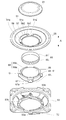
- FIG. 1 is an exploded perspective view for explaining a first embodiment of the speaker unit according to the present invention
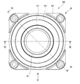
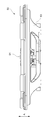
- FIG. 2 is a front view when FIG. 1 is assembled
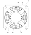
- FIG. 3 is a back view of
- FIG. 5 is a V direction arrow view of FIG. 2
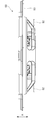
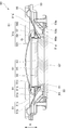
- FIG. 6 is a sectional view taken along the line VI-VI of FIG. 2
- FIG. 7 is a sectional view taken along the line VII-VII of FIG.
- the outer peripheral portion 51 b of the diaphragm 51 is attached to the frame 53 via the edge 55.
- the diaphragm 51 has a shape in which the center is recessed from the outer peripheral portion 51b to the inner peripheral portion 51c, and a circular central hole 51a penetrating in the thickness direction of the diaphragm 51 is formed at the center (inner peripheral portion 51c).
- the frame 53 has a shape in which the center is indented in the same direction as the diaphragm 51, has a bottom 53a at the center, and a hole 53b penetrating in the thickness direction is formed in the bottom 53a.
- a magnetic circuit 61 is provided at the bottom 53 a of the frame 53.
- the magnetic circuit 61 includes a yoke 63, a magnet 65, and a pole piece 66.
- the yoke 63 is made of a hard magnetic material and has a cylindrical shape with a bottom, one surface of which is an open surface, and the base 67 attached to the hole 53 b of the bottom 53 a of the frame 53 and the vibration of the diaphragm 51 from the periphery of the base 67
- a cylindrical portion 69 extending in the direction away from the bottom 53a of the frame 53 along the direction (FIGS. 1 and 4 in the direction of the arrow A in FIG. 4) and serving as the outer peripheral cylindrical portion of the magnetic circuit 61; Have (see Figure 6). That is, the cylindrical portion 69 is the outer peripheral cylindrical portion in the present invention.
- the cylindrical portion 69 is formed with a plurality of upright wall portions 69c and slits 69a extending toward the base 67 along the vibration direction (arrow A direction) of the diaphragm 51 from the end on the open surface side.
- the cylindrical portion 69 is composed of four slits 69 a and four standing wall portions 69 c divided by the four slits 69 a.
- the base portion 67 is formed with four attaching portions 67a extending outward, corresponding to the slits 69a. Positioning of the magnetic circuit 61 with respect to the frame 53 is achieved by fitting the four attachment portions 67 a into the four attachment recesses 53 c formed on the periphery of the hole 53 b of the frame 53.
- the magnet 65 is formed in a disk shape and mounted on the base 67 of the yoke 63.
- the magnetization direction of the magnet 65 is the vibration direction (arrow A direction) of the diaphragm 51.
- a disc-shaped pole piece 66 made of a hardly magnetic material is placed on the magnet 65. Therefore, an annular space is formed between the inner circumferential surface of the cylindrical portion 69 of the yoke 63 and the outer circumferential surface of the pole piece 66.
- This annular space is a magnetic gap G in which a substantially uniform magnetic field is generated in the circumferential direction. It has become.
- the inner circumferential portion 51c of the diaphragm 51 includes four insertion holes 57 through which the vertical wall 69c of the yoke 63 of the magnetic circuit 61 is inserted, and four insertion portions 59 through which the slits 69a of the yoke 63 of the magnetic circuit 61 are inserted.
- the insertion hole 57 penetrates in the vibration direction (thickness direction) of the diaphragm 51. This insertion hole 57 is used as a standing wall insertion portion in the present invention.
- the inner peripheral portion 51 c of the diaphragm 51 is a ring-shaped inner annular portion 591 formed on the inner peripheral side of the diaphragm 51 than the respective insertion holes 57, and the outer peripheral side of the diaphragm 51 than the respective insertion holes 57. And a ring-shaped outer annular portion 592 formed thereon. Therefore, each insertion hole 57 is formed between the inner annular portion 591 and the outer annular portion 592.
- the central hole 51a of the diaphragm 51 is formed by the inner peripheral surface of the inner annular portion 591 (the inner peripheral surface of the inner peripheral portion 51c). The inner circumferential surface of the inner annular portion 591 is connected to the voice coil 85.
- each insertion portion 59 may be connected to the voice coil 85 without forming the inner annular portion 591.
- Voice coil 85 includes cylindrical bobbin 81 disposed between the inner peripheral surface of cylindrical portion 69 (vertical wall portion 69 c) of yoke 63 and the outer peripheral surface of magnet 65 and pole piece 66, and the outer peripheral surface of bobbin 81. And a coil 83 wound around the. Then, the bobbin 81 and the inner circumferential surface of the central hole 51a of the diaphragm 51 (the inner circumferential surface of the inner circumferential portion 51c of the diaphragm 51) are connected so that the coil 83 is positioned at the magnetic gap G of the magnetic circuit 61. ing.
- the inner peripheral surface (inner peripheral surface of the inner annular portion 591) of the inner peripheral portion 51c of the diaphragm 51 and the voice coil 85 are connected via the slits 69a of the yoke 63 of the magnetic circuit 61.
- the inner peripheral surface of the central hole 51 a of the diaphragm 51 (the inner peripheral surface of the inner peripheral portion 51 c of the diaphragm 51) is connected to the lower portion of the bobbin 81.
- the outer peripheral surface of the bobbin 81 disposed on the base 67 side of the yoke 63 that is, the inner peripheral surface of the central hole 51a of the diaphragm 51 (diaphragm)
- the inner circumferential surface 51 of the inner circumferential portion 51 c is connected.
- the outer peripheral portion 51b and the inner peripheral portion 51c are integrally formed. Further, the thickness of the inner peripheral portion 51c of the diaphragm 51 is formed larger (thicker) than the thickness of the outer peripheral portion 51b. Furthermore, the inner circumferential portion 51 c of the diaphragm 51 is formed in a shape that gradually reduces in diameter toward the lower side in the vibration direction (arrow A direction), and in the inner circumferential portion 51 c of the diaphragm 51 from the outer annular portion 592 The inner annular portion 591 is disposed below the vibration direction (arrow A direction). Further, as shown in FIG.
- the thickness (t1) of the bonding surface between the diaphragm 51 and the bobbin 81 is larger than the thickness (t2) of the outer peripheral portion 51b ((2) Thick) is formed.
- the dust cap 91 which constitutes a part of the diaphragm 51 is used to prevent the infiltration of dust and the like from the center hole 51 a of the diaphragm 51.
- the dust cap 91 is connected to the dome-shaped dome portion 91 c covering the opening of the bobbin 81, the diaphragm connection portion 91 a connected to the diaphragm 51, and the voice coil 85 as shown in FIGS. 6 and 7.
- a voice coil connection portion 91b is formed on the outermost side of the dust cap 91 and covers the upper side of the inner peripheral portion 51 c of the diaphragm 51.
- the voice coil connection portion 91 b is formed on the inner peripheral side of the diaphragm connection portion 91 a.
- the voice coil connection portion 91 b of the dust cap 91 is connected to the outer peripheral surface (upper part of the bobbin 81) of the bobbin 81 above the coil 83 of the voice coil 85.
- the outer peripheral edge of the diaphragm connecting portion 91a of the dust cap 91 is connected to the outer peripheral side of the inner peripheral portion 51c located near the boundary between the inner peripheral portion 51c and the outer peripheral portion 51b of the diaphragm 51.
- the inner peripheral surface of the center hole 51 a of the diaphragm 51 (the inner peripheral surface of the inner annular portion 591) is connected to the outer peripheral surface of the lower bobbin 81 of the coil 83.
- the inner peripheral surface of the inner peripheral portion 51c of the diaphragm 51 is connected to the lower portion of the bobbin 81, and the outer peripheral side of the inner peripheral portion 51c is connected to the outer peripheral edge of the diaphragm connecting portion 91a of the dust cap 91.
- a voice coil connection portion 91 b 91 is connected to the top of the bobbin 81.
- the upper side of the inner peripheral portion 51c of the diaphragm 51 is covered with the diaphragm connection portion 91a, so that the inner peripheral portion 51c of the diaphragm 51 and the diaphragm connection of the dust cap 91 are connected to the inside of the diaphragm connection portion 91a.
- An internal space surrounded by the portion 91 a and the voice coil 85 is formed.
- a terminal 52 is provided on the frame 53, and the terminal 52 and the coil 83 of the voice coil 85 are electrically connected by a tinsel wire (lead wire) not shown.
- the electrical signal input to the terminal 52 flows to the coil 83 of the voice coil 85 via the tinsel wire. Since the coil 83 is disposed in the magnetic field generated by the magnetic circuit 61, the diaphragm 51 vibrates in the direction of arrow A by the driving force generated in the coil 83 (voice coil 85), and a sound is emitted.
- the diaphragm 51 has an insertion hole 57 through which the vertical wall 69 c of the cylindrical portion 69 of the magnetic circuit 61 is inserted, and an insertion portion 59 which is inserted through the slit 69 a of the cylindrical portion 69.
- the bonding surface of the diaphragm 51 and the voice coil 85 can be disposed below the tip (the tip of the yoke 63). Therefore, the speaker unit 50 can be thinned without lowering the height of the diaphragm 51 in the vibration direction.
- the difference in height of the cone shape of the diaphragm 51 can be sufficiently secured, it is possible to suppress the reduction of the rigidity of the diaphragm 51 as a whole.
- the speaker unit 50 can be reliably thinned without lowering the height of the plate 51 in the vibration direction.
- the dust cap 91 includes the diaphragm connection portion 91 a connected to the diaphragm 51 and the voice coil connection portion 91 b connected to the voice coil 85, thereby increasing the rigidity of the diaphragm 51. Therefore, the speed at which the sound propagates in the diaphragm 51 is increased, the reaction (transjet characteristics) is good, and a precise and delicate sound can be reproduced.
- the rigidity of the diaphragm 51 can be increased by integrally molding the inner peripheral portion 51 c and the outer peripheral portion 51 b of the diaphragm 51.
- the thickness (t1) in the vibration direction of the bonding surface of the inner peripheral portion 51c of the diaphragm 51 and the bobbin 81 is larger than the thickness (t2) of the outer peripheral portion 51b of the diaphragm 51, so that the bobbin 81 and the diaphragm
- the bonding area with 51 can be increased, and the durability of the speaker unit 50 can be improved.
- the speaker unit 50 configured to have no damper for supporting the voice coil, as shown in FIGS. 8 and 9, the speaker unit is further provided with a damper for supporting the voice coil. It is good.
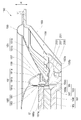
- FIG. 8 is a half sectional view of a speaker unit 150 according to a second embodiment of the present invention
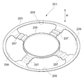
- FIG. 9 is a perspective view of the damper 201 of FIG.
- the outer peripheral portion 151 b of the diaphragm 151 is attached to the frame 153 via the edge 155.
- the diaphragm 151 has a shape in which the center is recessed from the outer peripheral portion 151b to the inner peripheral portion 151c, and a circular central hole 151a penetrating in the thickness direction of the diaphragm 151 is formed at the center (inner peripheral portion 151c).
- the frame 153 has a center indented in the same direction as the diaphragm 151, has a bottom portion 153a at the center, and a hole 153b penetrating in the thickness direction is formed in the bottom portion 153a.
- a magnetic circuit 161 is provided at the bottom 153 a of the frame 153.
- the magnetic circuit 161 includes a yoke 163, a magnet 165, and a pole piece 166.
- the yoke 163 is made of a hard magnetic material and has a cylindrical shape with a bottom, one surface of which is an open surface, and the base 167 attached to the hole 153 b of the bottom 153 a of the frame 153 and the vibration of the diaphragm 151 from the periphery of the base 167
- a cylindrical portion 169 extends in the direction away from the bottom portion 153 a of the frame 153 along the direction (arrow A ′ direction in FIG. 8), and functions as an outer peripheral cylindrical portion of the magnetic circuit 161. That is, the cylindrical portion 169 is the outer peripheral cylindrical portion in the present invention.
- the cylindrical portion 169 is formed with a plurality of upright wall portions 169c and slits 169a extending toward the base portion 167 along the vibration direction (arrow A 'direction) of the diaphragm 151 from the end on the open surface side.
- the four slits 169 a in the present embodiment are provided at a pitch of 90 ° along the circumferential direction of the cylindrical portion 169. Therefore, the cylindrical portion 169 is composed of four slits 169 a and four upright wall portions 169 c divided by the four slits 169 a.
- the magnet 165 is formed in a disk shape and mounted on the base 167 of the yoke 163.
- the magnetization direction of the magnet 165 is the vibration direction (arrow A ′ direction) of the diaphragm 151.
- a disc-shaped pole piece 166 made of a hardly magnetic material is mounted on the magnet 165. Therefore, an annular space is formed between the inner circumferential surface of the cylindrical portion 169 of the yoke 163 and the outer circumferential surface of the pole piece 166, and the annular space is a magnetic gap G in which a substantially uniform magnetic field is generated in the circumferential direction. It is'.
- the diaphragm 151 has the same shape as the diaphragm 51 of the first embodiment, and four insertion holes (vertical wall insertion portions through which the vertical wall portion 169c of the yoke 163 of the magnetic circuit 161 is inserted through the inner peripheral portion 151c of the horizontal plate 151). ) And four insertion parts 159 which are inserted into the slits 169a of the yoke 163 of the magnetic circuit 161 are alternately formed along the circumferential direction.
- the insertion hole 157 penetrates in the vibration direction (thickness direction) of the diaphragm 151.
- Voice coil 185 has a cylindrical bobbin 181 disposed between the inner peripheral surface of cylindrical portion 169 (vertical wall portion 169c) of yoke 163 and the outer peripheral surface of magnet 165 and pole piece 166, and the outer peripheral surface of bobbin 181 And a coil 183 wound around the. Then, the bobbin 181 is connected to the inner circumferential surface of the central hole 151a of the diaphragm 151 (the inner circumferential surface of the inner circumferential portion 151c of the diaphragm 151) so that the coil 183 is positioned at the magnetic gap G 'of the magnetic circuit 161. It is done. That is, the inner peripheral surface of the inner peripheral portion 151 c of the diaphragm 151 and the voice coil 185 are connected via the slit 169 a of the yoke 163 of the magnetic circuit 161.
- the direction in which the diaphragm 151 moves away from the magnetic circuit 161 (the base 167 of the yoke 163) is upward, and the direction in which the diaphragm 151 approaches the magnetic circuit 161 is downward.
- the inner peripheral surface of the central hole 151a of the diaphragm 151 (the inner peripheral surface of the inner peripheral portion 151c of the diaphragm 151) is connected to the lower portion of the bobbin 181.
- the inner circumferential surface 151 of the inner circumferential portion 151 c is connected.
- the diaphragm 151 is integrally formed with the outer peripheral part 151b and the inner peripheral part 151c. Further, the thickness of the inner peripheral portion 151c of the diaphragm 151 is formed larger (thicker) than the thickness of the outer peripheral portion 151b.
- the dust cap 191 which constitutes a part of the diaphragm 151 is used to prevent the infiltration of dust and the like from the center hole 151 a of the diaphragm 151.
- the dust cap 191 has a dome-shaped dome portion 191 c covering the opening of the bobbin 181, a diaphragm connection portion 191 a connected to the diaphragm 151, and a voice coil connection portion 191 b connected to the voice coil 185. ing.
- the diaphragm connection portion 191 a is formed on the outermost side of the dust cap 191 and covers the upper side of the inner peripheral portion 151 c of the diaphragm 151.
- the voice coil connection portion 191b is formed on the inner peripheral side of the diaphragm connection portion 191a.
- the voice coil connection portion 191 b of the dust cap 191 is connected to the outer peripheral surface (upper part of the bobbin 181) of the bobbin 181 above the coil 183 of the voice coil 185.
- the outer peripheral edge of the diaphragm connecting portion 191a of the dust cap 191 is connected to the outer peripheral side of the inner peripheral portion 51c located near the boundary between the inner peripheral portion 151c and the outer peripheral portion 151b of the diaphragm 151.
- the inner peripheral surface of the central hole 151 a of the diaphragm 151 is connected to the outer peripheral surface of the lower bobbin 181 of the coil 183.
- the inner peripheral surface of the inner peripheral portion 151c of the diaphragm 151 is connected to the lower portion of the bobbin 181, and the outer peripheral side of the inner peripheral portion 151c is connected to the outer peripheral edge of the diaphragm connecting portion 191a of the dust cap 191.
- a voice coil connection 191 b is connected to the top of the bobbin 181.
- the upper side of the inner peripheral portion 151c of the diaphragm 151 is covered with the diaphragm connection portion 191a, so that the inner peripheral portion 151c of the diaphragm 151 and the diaphragm connection of the dust cap 191 are connected to the inside of the diaphragm connection portion 191a.
- An internal space surrounded by the portion 191a and the voice coil 185 is formed.
- the damper 201 supporting the voice coil 185 is provided. As shown in FIG. 9, the damper 201 bridges the outer ring portion 203 connected to the frame 153, the inner ring portion 205 connected to the voice coil 185, the outer ring portion 203 and the inner ring portion 205. And an opening 209 surrounded by the outer ring portion 203, the inner ring portion 205, and the bridge portion 207.
- the outer ring portion 203 and the inner ring portion 205 are formed concentrically, and the inner ring portion 205 is disposed inside the outer ring portion 203.
- the outer ring portion 203 is connected to the lower side of the frame 153, and is connected to the frame 153 below the edge 155. Further, the inner ring portion 205 is connected to the bobbin 181 further below the connection portion between the bobbin 181 of the voice coil 185 and the diaphragm 151.
- the bridge portion 207 extends in the radial direction of the outer ring portion 203 and is provided to bridge the outer ring portion 203 and the inner ring portion 205.
- the damper 201 has four bridge portions 207.
- the openings 209 pass through in the vibration direction of the diaphragm 151 (the thickness direction of the damper 201), and four openings the same as the number of the bridge portions 207 are provided.
- crosslinking part 207 and the opening part 209 is not restricted to four each, Other numbers can be provided.
- Each bridge portion 207 is inserted through each slit 169 a of the yoke 163 of the magnetic circuit 161. Further, the cross-sectional shape along the radial direction of the bridge portion 207 is a waveform, and the bridge portion 207 is bent in the vibration direction (the arrow A ′ direction) of the diaphragm 151 to support the damper 201.
- the voice coil 185 is movable in the arrow A 'direction. Further, each opening 209 passes through each upright wall portion 169 c of the yoke 163 of the magnetic circuit 161.
- An electrical signal flows to the coil 183 of the voice coil 185. Since the coil 183 is disposed in the magnetic field generated by the magnetic circuit 161, the diaphragm 151 vibrates in the direction of the arrow A ′ by the driving force generated in the coil 183 (voice coil 185), and a sound is emitted.
- the diaphragm 151 has an insertion hole 157 through which the upright wall portion 169 c of the cylindrical portion 169 of the magnetic circuit 161 is inserted, and an insertion portion 159 which is inserted through the slit 169 a of the cylindrical portion 169.
- the bonding surface of the diaphragm 151 and the voice coil 185 can be disposed below the front end (yoke 166). Therefore, the speaker unit 150 can be thinned without lowering the height in the vibration direction of the diaphragm 151.
- the difference in height of the cone shape of the diaphragm 151 can be sufficiently secured, it is possible to suppress the reduction of the rigidity of the whole diaphragm 151.
- the portion driven and vibrated by the voice coil 185 is only the diaphragm 151 and the mass is reduced, so that a strong magnetic circuit is not required, and the cost can be reduced.
- the dust cap 191 has the diaphragm connection portion 191 a connected to the diaphragm 151 and the voice coil connection portion 191 b connected to the voice coil 185, whereby the rigidity of the diaphragm 151 is increased. Therefore, the speed at which the sound propagates in the diaphragm 151 is increased, the reaction (transjet characteristics) is good, and a precise and delicate sound can be reproduced.
- the rigidity of the diaphragm 151 can be increased by integrally molding the inner peripheral portion 151 c and the outer peripheral portion 151 b of the diaphragm 151.
- the voice coil 185 can be supported not only on the frame 153 via the edge 155 and the vibrating body 151, but also on the frame 153 via the damper 201. Therefore, the vibration in the vibration direction of the voice coil 185 can be stably supported by the edge 155, the vibrating body 151, and the damper 201. Further, even if the diaphragm 151 has a large diameter and the voice coil 185 is enlarged, it can be stably supported by the damper 201, and the sound quality is improved.
Abstract
Le problème décrit par la présente invention est de fournir une unité de haut-parleur qui est peu coûteuse, a une bonne qualité sonore, et peut être rendue mince. A cet effet, l'invention concerne une unité de haut-parleur qui comprend : un circuit magnétique 61 dans lequel un espace servant de fente magnétique G est formé sur le côté intérieur d'une section cylindrique 69; une bobine acoustique 85 disposée à l'intérieur de l'espace magnétique G; et un diaphragme 51 qui a un trou central de pénétration 51a formé au centre, est supporté sur un cadre 53 sur le côté avec une section périphérique externe 51b, et a la surface périphérique interne d'une section périphérique interne 51c reliée à la bobine acoustique 85. La section cylindrique 69 du circuit magnétique 61 a des parties de paroi verticale 69c et des fentes 69a formées le long de la direction de vibration A du diaphragme 51, et la section périphérique interne 51c du diaphragme 51 a des trous d'insertion (parties d'insertion de paroi verticale) 57 à travers lesquelles les parties de paroi verticale 69c sont insérées et des parties d'insertion 59 à insérer dans les fentes 69a.
Priority Applications (4)
| Application Number | Priority Date | Filing Date | Title |
|---|---|---|---|
| JP2019547935A JP6990250B2 (ja) | 2017-10-13 | 2018-08-22 | スピーカユニット |
| US16/755,622 US11284198B2 (en) | 2017-10-13 | 2018-08-22 | Speaker unit |
| CN201880065429.5A CN111194560B (zh) | 2017-10-13 | 2018-08-22 | 扬声器单元 |
| EP18866099.7A EP3697105A4 (fr) | 2017-10-13 | 2018-08-22 | Unité de haut-parleur |
Applications Claiming Priority (2)
| Application Number | Priority Date | Filing Date | Title |
|---|---|---|---|
| JP2017199021 | 2017-10-13 | ||
| JP2017-199021 | 2017-10-13 |
Publications (1)
| Publication Number | Publication Date |
|---|---|
| WO2019073697A1 true WO2019073697A1 (fr) | 2019-04-18 |
Family
ID=66101419
Family Applications (1)
| Application Number | Title | Priority Date | Filing Date |
|---|---|---|---|
| PCT/JP2018/030983 WO2019073697A1 (fr) | 2017-10-13 | 2018-08-22 | Unité de haut-parleur |
Country Status (5)
| Country | Link |
|---|---|
| US (1) | US11284198B2 (fr) |
| EP (1) | EP3697105A4 (fr) |
| JP (1) | JP6990250B2 (fr) |
| CN (1) | CN111194560B (fr) |
| WO (1) | WO2019073697A1 (fr) |
Cited By (1)
| Publication number | Priority date | Publication date | Assignee | Title |
|---|---|---|---|---|
| WO2022006964A1 (fr) * | 2020-07-06 | 2022-01-13 | 瑞声声学科技(深圳)有限公司 | Haut-parleur |
Citations (6)
| Publication number | Priority date | Publication date | Assignee | Title |
|---|---|---|---|---|
| JPS61396U (ja) * | 1984-06-04 | 1986-01-06 | オンキヨー株式会社 | 平板型スピ−カ− |
| JPH01225299A (ja) * | 1988-03-04 | 1989-09-08 | Mitsubishi Electric Corp | コーンスピーカーの振動板結合装置 |
| JPH07154896A (ja) * | 1993-11-29 | 1995-06-16 | Matsushita Electric Ind Co Ltd | スピーカ |
| JP2002078082A (ja) | 2000-09-04 | 2002-03-15 | Matsushita Electric Ind Co Ltd | スピーカ |
| JP2002159091A (ja) * | 2000-11-20 | 2002-05-31 | Matsushita Electric Ind Co Ltd | スピーカ及び振動板並びに振動板の製造方法 |
| JP2011004308A (ja) * | 2009-06-22 | 2011-01-06 | Foster Electric Co Ltd | スピーカ装置 |
Family Cites Families (24)
| Publication number | Priority date | Publication date | Assignee | Title |
|---|---|---|---|---|
| JPS5856600A (ja) * | 1981-09-30 | 1983-04-04 | Hitachi Ltd | 平面形スピ−カ |
| JPS60155278A (ja) | 1983-11-21 | 1985-08-15 | Somar Corp | 粉体塗料用エポキシ樹脂組成物 |
| DE3929266C1 (fr) * | 1989-09-02 | 1991-01-03 | Mercedes-Benz Aktiengesellschaft, 7000 Stuttgart, De | |
| JP3260062B2 (ja) * | 1995-09-04 | 2002-02-25 | 株式会社ケンウッド | スピーカ |
| JP3505037B2 (ja) * | 1996-05-23 | 2004-03-08 | パイオニア株式会社 | スピーカ |
| CN1179692A (zh) * | 1996-05-23 | 1998-04-22 | 日本先锋公司 | 扬声器 |
| JPH09327087A (ja) * | 1996-06-06 | 1997-12-16 | Matsushita Electric Ind Co Ltd | ダブルコーンスピーカ |
| EP1229759B1 (fr) * | 2000-09-04 | 2008-10-15 | Matsushita Electric Industrial Co., Ltd. | Haut-parleur |
| EP1324632B1 (fr) * | 2001-06-11 | 2009-07-29 | Panasonic Corporation | Haut parleur |
| US6968071B2 (en) * | 2003-01-15 | 2005-11-22 | Chao-Lang Wang | Speaker having magnetic member installed on diaphragm |
| JP3651470B2 (ja) * | 2003-03-31 | 2005-05-25 | 松下電器産業株式会社 | スピーカ |
| JP2005159506A (ja) * | 2003-11-21 | 2005-06-16 | Pioneer Electronic Corp | スピーカ装置 |
| JP4610890B2 (ja) * | 2003-12-24 | 2011-01-12 | パイオニア株式会社 | スピーカ装置 |
| JP2005252924A (ja) * | 2004-03-08 | 2005-09-15 | Matsushita Electric Ind Co Ltd | スピーカ |
| CN200973173Y (zh) * | 2006-11-16 | 2007-11-07 | 常州美欧电子有限公司 | 振动发声器 |
| CN200997173Y (zh) | 2006-12-05 | 2007-12-26 | 哈尔滨自动化仪表研究所 | 供热温度检测仪 |
| JP5190033B2 (ja) * | 2009-07-03 | 2013-04-24 | ホシデン株式会社 | 振動センサ |
| CN101626535B (zh) * | 2009-08-17 | 2014-06-18 | 瑞声声学科技(深圳)有限公司 | 发声器 |
| CN102932716A (zh) * | 2011-08-08 | 2013-02-13 | 美隆工业股份有限公司 | 内支架喇叭结构 |
| US9078059B2 (en) * | 2012-08-07 | 2015-07-07 | Jabil Circuit (Beijing), Ltd. | Transducer |
| CN103118320B (zh) * | 2013-01-18 | 2015-11-11 | 歌尔声学股份有限公司 | 一种超薄扬声器模组 |
| CN104822115B (zh) * | 2015-05-08 | 2018-11-02 | 歌尔股份有限公司 | 一种扬声器装置 |
| WO2017149984A1 (fr) * | 2016-02-29 | 2017-09-08 | パナソニックIpマネジメント株式会社 | Haut-parleur |
| JP2020114308A (ja) | 2019-01-18 | 2020-07-30 | 株式会社三共 | 遊技機 |
-
2018
- 2018-08-22 US US16/755,622 patent/US11284198B2/en active Active
- 2018-08-22 JP JP2019547935A patent/JP6990250B2/ja active Active
- 2018-08-22 EP EP18866099.7A patent/EP3697105A4/fr active Pending
- 2018-08-22 WO PCT/JP2018/030983 patent/WO2019073697A1/fr unknown
- 2018-08-22 CN CN201880065429.5A patent/CN111194560B/zh active Active
Patent Citations (6)
| Publication number | Priority date | Publication date | Assignee | Title |
|---|---|---|---|---|
| JPS61396U (ja) * | 1984-06-04 | 1986-01-06 | オンキヨー株式会社 | 平板型スピ−カ− |
| JPH01225299A (ja) * | 1988-03-04 | 1989-09-08 | Mitsubishi Electric Corp | コーンスピーカーの振動板結合装置 |
| JPH07154896A (ja) * | 1993-11-29 | 1995-06-16 | Matsushita Electric Ind Co Ltd | スピーカ |
| JP2002078082A (ja) | 2000-09-04 | 2002-03-15 | Matsushita Electric Ind Co Ltd | スピーカ |
| JP2002159091A (ja) * | 2000-11-20 | 2002-05-31 | Matsushita Electric Ind Co Ltd | スピーカ及び振動板並びに振動板の製造方法 |
| JP2011004308A (ja) * | 2009-06-22 | 2011-01-06 | Foster Electric Co Ltd | スピーカ装置 |
Cited By (1)
| Publication number | Priority date | Publication date | Assignee | Title |
|---|---|---|---|---|
| WO2022006964A1 (fr) * | 2020-07-06 | 2022-01-13 | 瑞声声学科技(深圳)有限公司 | Haut-parleur |
Also Published As
| Publication number | Publication date |
|---|---|
| JP6990250B2 (ja) | 2022-01-12 |
| EP3697105A4 (fr) | 2020-12-09 |
| EP3697105A1 (fr) | 2020-08-19 |
| JPWO2019073697A1 (ja) | 2020-10-22 |
| US20200336838A1 (en) | 2020-10-22 |
| US11284198B2 (en) | 2022-03-22 |
| CN111194560B (zh) | 2022-02-22 |
| CN111194560A (zh) | 2020-05-22 |
Similar Documents
| Publication | Publication Date | Title |
|---|---|---|
| US8290199B2 (en) | Loudspeaker suspension | |
| EP2262281B1 (fr) | Haut-parleur | |
| JP6005974B2 (ja) | 薄型ラウドスピーカ変換器用の強化振動板 | |
| JP5049883B2 (ja) | スピーカ | |
| US8520885B2 (en) | Composite speaker | |
| JP6029846B2 (ja) | ラウドスピーカ磁石組立体 | |
| KR101499514B1 (ko) | 장방형의 일체형 투웨이 스피커 | |
| JP6045177B2 (ja) | チャネルを有するラウドスピーカ磁石 | |
| EP3203758B1 (fr) | Transducteur électroacoustique | |
| US20070098209A1 (en) | Integrated multi yoke for multi polar loudspeakers | |
| WO2022121740A1 (fr) | Haut-parleur et dispositif électronique | |
| KR101590178B1 (ko) | 통전기능을 갖는 서스펜션이 적용된 박형 스피커유니트 | |
| JP6029845B2 (ja) | 薄型ラウドスピーカサスペンションシステム | |
| US20080285787A1 (en) | Thin loudspeaker | |
| WO2019073697A1 (fr) | Unité de haut-parleur | |
| JP4133457B2 (ja) | スピーカ | |
| JP2001268690A (ja) | スピーカ | |
| JP7202249B2 (ja) | 電気音響変換器 | |
| JP2002078082A (ja) | スピーカ | |
| US11930342B2 (en) | Electro-acoustic transducer | |
| JP2003023695A (ja) | スピーカ装置 | |
| JP2002300695A (ja) | スピーカ | |
| JP2017139616A (ja) | スピーカ装置 | |
| JP2001016687A (ja) | スピーカ用キャップ一体型ダンパ | |
| JP2005109851A (ja) | スピーカ |
Legal Events
| Date | Code | Title | Description |
|---|---|---|---|
| 121 | Ep: the epo has been informed by wipo that ep was designated in this application |
Ref document number: 18866099 Country of ref document: EP Kind code of ref document: A1 |
|
| ENP | Entry into the national phase |
Ref document number: 2019547935 Country of ref document: JP Kind code of ref document: A |
|
| NENP | Non-entry into the national phase |
Ref country code: DE |
|
| ENP | Entry into the national phase |
Ref document number: 2018866099 Country of ref document: EP Effective date: 20200513 |