WO2019069820A1 - 車両用内装材 - Google Patents
車両用内装材 Download PDFInfo
- Publication number
- WO2019069820A1 WO2019069820A1 PCT/JP2018/036360 JP2018036360W WO2019069820A1 WO 2019069820 A1 WO2019069820 A1 WO 2019069820A1 JP 2018036360 W JP2018036360 W JP 2018036360W WO 2019069820 A1 WO2019069820 A1 WO 2019069820A1
- Authority
- WO
- WIPO (PCT)
- Prior art keywords
- wall
- lens
- interior material
- light guide
- guide member
- Prior art date
- Legal status (The legal status is an assumption and is not a legal conclusion. Google has not performed a legal analysis and makes no representation as to the accuracy of the status listed.)
- Ceased
Links
Images



Classifications
-
- B—PERFORMING OPERATIONS; TRANSPORTING
- B60—VEHICLES IN GENERAL
- B60Q—ARRANGEMENT OF SIGNALLING OR LIGHTING DEVICES, THE MOUNTING OR SUPPORTING THEREOF OR CIRCUITS THEREFOR, FOR VEHICLES IN GENERAL
- B60Q3/00—Arrangement of lighting devices for vehicle interiors; Lighting devices specially adapted for vehicle interiors
- B60Q3/50—Mounting arrangements
- B60Q3/51—Mounting arrangements for mounting lighting devices onto vehicle interior, e.g. onto ceiling or floor
-
- B—PERFORMING OPERATIONS; TRANSPORTING
- B60—VEHICLES IN GENERAL
- B60J—WINDOWS, WINDSCREENS, NON-FIXED ROOFS, DOORS, OR SIMILAR DEVICES FOR VEHICLES; REMOVABLE EXTERNAL PROTECTIVE COVERINGS SPECIALLY ADAPTED FOR VEHICLES
- B60J5/00—Doors
-
- B—PERFORMING OPERATIONS; TRANSPORTING
- B60—VEHICLES IN GENERAL
- B60Q—ARRANGEMENT OF SIGNALLING OR LIGHTING DEVICES, THE MOUNTING OR SUPPORTING THEREOF OR CIRCUITS THEREFOR, FOR VEHICLES IN GENERAL
- B60Q3/00—Arrangement of lighting devices for vehicle interiors; Lighting devices specially adapted for vehicle interiors
- B60Q3/20—Arrangement of lighting devices for vehicle interiors; Lighting devices specially adapted for vehicle interiors for lighting specific fittings of passenger or driving compartments; mounted on specific fittings of passenger or driving compartments
- B60Q3/217—Doors, e.g. door sills; Steps
-
- B—PERFORMING OPERATIONS; TRANSPORTING
- B60—VEHICLES IN GENERAL
- B60Q—ARRANGEMENT OF SIGNALLING OR LIGHTING DEVICES, THE MOUNTING OR SUPPORTING THEREOF OR CIRCUITS THEREFOR, FOR VEHICLES IN GENERAL
- B60Q3/00—Arrangement of lighting devices for vehicle interiors; Lighting devices specially adapted for vehicle interiors
- B60Q3/20—Arrangement of lighting devices for vehicle interiors; Lighting devices specially adapted for vehicle interiors for lighting specific fittings of passenger or driving compartments; mounted on specific fittings of passenger or driving compartments
- B60Q3/225—Small compartments, e.g. glove compartments
-
- B—PERFORMING OPERATIONS; TRANSPORTING
- B60—VEHICLES IN GENERAL
- B60Q—ARRANGEMENT OF SIGNALLING OR LIGHTING DEVICES, THE MOUNTING OR SUPPORTING THEREOF OR CIRCUITS THEREFOR, FOR VEHICLES IN GENERAL
- B60Q3/00—Arrangement of lighting devices for vehicle interiors; Lighting devices specially adapted for vehicle interiors
- B60Q3/50—Mounting arrangements
- B60Q3/54—Lighting devices embedded in interior trim, e.g. in roof liners
-
- B—PERFORMING OPERATIONS; TRANSPORTING
- B60—VEHICLES IN GENERAL
- B60Q—ARRANGEMENT OF SIGNALLING OR LIGHTING DEVICES, THE MOUNTING OR SUPPORTING THEREOF OR CIRCUITS THEREFOR, FOR VEHICLES IN GENERAL
- B60Q3/00—Arrangement of lighting devices for vehicle interiors; Lighting devices specially adapted for vehicle interiors
- B60Q3/60—Arrangement of lighting devices for vehicle interiors; Lighting devices specially adapted for vehicle interiors characterised by optical aspects
- B60Q3/62—Arrangement of lighting devices for vehicle interiors; Lighting devices specially adapted for vehicle interiors characterised by optical aspects using light guides
- B60Q3/64—Arrangement of lighting devices for vehicle interiors; Lighting devices specially adapted for vehicle interiors characterised by optical aspects using light guides for a single lighting device
-
- B—PERFORMING OPERATIONS; TRANSPORTING
- B60—VEHICLES IN GENERAL
- B60Q—ARRANGEMENT OF SIGNALLING OR LIGHTING DEVICES, THE MOUNTING OR SUPPORTING THEREOF OR CIRCUITS THEREFOR, FOR VEHICLES IN GENERAL
- B60Q3/00—Arrangement of lighting devices for vehicle interiors; Lighting devices specially adapted for vehicle interiors
- B60Q3/70—Arrangement of lighting devices for vehicle interiors; Lighting devices specially adapted for vehicle interiors characterised by the purpose
- B60Q3/78—Arrangement of lighting devices for vehicle interiors; Lighting devices specially adapted for vehicle interiors characterised by the purpose for generating luminous strips, e.g. for marking trim component edges
-
- B—PERFORMING OPERATIONS; TRANSPORTING
- B60—VEHICLES IN GENERAL
- B60R—VEHICLES, VEHICLE FITTINGS, OR VEHICLE PARTS, NOT OTHERWISE PROVIDED FOR
- B60R13/00—Elements for body-finishing, identifying, or decorating; Arrangements or adaptations for advertising purposes
- B60R13/02—Internal Trim mouldings ; Internal Ledges; Wall liners for passenger compartments; Roof liners
-
- F—MECHANICAL ENGINEERING; LIGHTING; HEATING; WEAPONS; BLASTING
- F21—LIGHTING
- F21V—FUNCTIONAL FEATURES OR DETAILS OF LIGHTING DEVICES OR SYSTEMS THEREOF; STRUCTURAL COMBINATIONS OF LIGHTING DEVICES WITH OTHER ARTICLES, NOT OTHERWISE PROVIDED FOR
- F21V17/00—Fastening of component parts of lighting devices, e.g. shades, globes, refractors, reflectors, filters, screens, grids or protective cages
- F21V17/08—Fastening of component parts of lighting devices, e.g. shades, globes, refractors, reflectors, filters, screens, grids or protective cages onto the supporting or suspending arrangements of the lighting device, e.g. power cords, standards
-
- F—MECHANICAL ENGINEERING; LIGHTING; HEATING; WEAPONS; BLASTING
- F21—LIGHTING
- F21V—FUNCTIONAL FEATURES OR DETAILS OF LIGHTING DEVICES OR SYSTEMS THEREOF; STRUCTURAL COMBINATIONS OF LIGHTING DEVICES WITH OTHER ARTICLES, NOT OTHERWISE PROVIDED FOR
- F21V5/00—Refractors for light sources
-
- F—MECHANICAL ENGINEERING; LIGHTING; HEATING; WEAPONS; BLASTING
- F21—LIGHTING
- F21V—FUNCTIONAL FEATURES OR DETAILS OF LIGHTING DEVICES OR SYSTEMS THEREOF; STRUCTURAL COMBINATIONS OF LIGHTING DEVICES WITH OTHER ARTICLES, NOT OTHERWISE PROVIDED FOR
- F21V5/00—Refractors for light sources
- F21V5/04—Refractors for light sources of lens shape
-
- G—PHYSICS
- G02—OPTICS
- G02B—OPTICAL ELEMENTS, SYSTEMS OR APPARATUS
- G02B6/00—Light guides; Structural details of arrangements comprising light guides and other optical elements, e.g. couplings
- G02B6/0001—Light guides; Structural details of arrangements comprising light guides and other optical elements, e.g. couplings specially adapted for lighting devices or systems
- G02B6/0005—Light guides; Structural details of arrangements comprising light guides and other optical elements, e.g. couplings specially adapted for lighting devices or systems the light guides being of the fibre type
- G02B6/001—Light guides; Structural details of arrangements comprising light guides and other optical elements, e.g. couplings specially adapted for lighting devices or systems the light guides being of the fibre type the light being emitted along at least a portion of the lateral surface of the fibre
-
- B—PERFORMING OPERATIONS; TRANSPORTING
- B60—VEHICLES IN GENERAL
- B60R—VEHICLES, VEHICLE FITTINGS, OR VEHICLE PARTS, NOT OTHERWISE PROVIDED FOR
- B60R13/00—Elements for body-finishing, identifying, or decorating; Arrangements or adaptations for advertising purposes
- B60R13/02—Internal Trim mouldings ; Internal Ledges; Wall liners for passenger compartments; Roof liners
- B60R13/0237—Side or rear panels
- B60R13/0243—Doors
-
- B—PERFORMING OPERATIONS; TRANSPORTING
- B60—VEHICLES IN GENERAL
- B60R—VEHICLES, VEHICLE FITTINGS, OR VEHICLE PARTS, NOT OTHERWISE PROVIDED FOR
- B60R7/00—Stowing or holding appliances inside vehicle primarily intended for personal property smaller than suit-cases, e.g. travelling articles, or maps
- B60R7/04—Stowing or holding appliances inside vehicle primarily intended for personal property smaller than suit-cases, e.g. travelling articles, or maps in driver or passenger space, e.g. using racks
- B60R7/046—Stowing or holding appliances inside vehicle primarily intended for personal property smaller than suit-cases, e.g. travelling articles, or maps in driver or passenger space, e.g. using racks mounted on door
-
- F—MECHANICAL ENGINEERING; LIGHTING; HEATING; WEAPONS; BLASTING
- F21—LIGHTING
- F21W—INDEXING SCHEME ASSOCIATED WITH SUBCLASSES F21K, F21L, F21S and F21V, RELATING TO USES OR APPLICATIONS OF LIGHTING DEVICES OR SYSTEMS
- F21W2106/00—Interior vehicle lighting devices
Definitions
- the present invention relates to an interior material for a vehicle mounted on a vehicle.
- a door lining provided on a vehicle door is provided with a linear light guiding member for propagating light from a light source and a lens provided along the light guiding member between a main body and a switch panel (E.g., Patent Document 1).
- the lens includes a groove for holding the light guide member, a holding portion held between the main body and the switch panel, and a hook for holding the light guide member in the through hole provided in the main body. Is coupled to the body through a lens. Part of the light from the light source is emitted from the side surface of the light guide member, passes through the pinching portion of the lens, and reaches the cabin.
- Patent Document 1 since the lens is held between the main body and the switch panel, the lens needs to be disposed at an appropriate position with respect to the main body and the switch panel at the time of assembly, and held between the both. Yes, not easy to assemble.
- the present invention is an interior material for a vehicle including an interior material body, a light guide member for guiding light from a light source, and a lens provided along the light guide member. It is an object of the present invention to provide a structure that can be easily coupled to a material body.
- the interior material (1) for a vehicle is linearly formed with an interior material main body (10, 11, 12) constituting an inner wall of a cabin, and the light from the light source is elongated A light guide member (17) for propagating in a direction and emitting light from the side surface, and a lens (18) for transmitting light emitted from the light guide member, the lens being the light guide member And a groove (26) extending along and receiving the light guide member, a first engaging portion (21) provided on one wall defining the groove, and the other wall defining the groove And the second engaging portion (22) provided on the second engaging portion, and the interior material main body includes the first engaged portion (34) engaged with the first engaging portion, and the second engaging portion.
- a second engaged portion (35) to be engaged, and elastically deformed so that one wall defining the groove and the other wall are close to each other And wherein the Rukoto.
- the first engaging portion and the first engaged portion can be easily coupled to the second engaging portion and the second engaged portion.
- the interior material body and the lens are coupled, and the lens and the light guide member can be easily attached to the interior material body.
- the lens may be a first wall (23) disposed along the light guide member, and a second wall (24) extending from an end of the first wall to the light guide member.
- the third wall (25), and the groove may be defined by the first wall, the second wall, and the third wall.
- the lens can be easily elastically deformed so as to bring the second wall and the third wall close to each other, and the groove can be formed in the lens.
- the interior material main body includes an interior material concave portion (29) for housing the light guide member and the lens, and the first engaging portion is separated from the light guide member of the second wall.
- the first engagement portion is a hole for receiving the first engagement portion formed in the wall defining the interior material recess
- the second engagement portion is the third wall.
- the second engaged portion is formed on the wall defining the interior material recess, and protrudes from the surface of the side away from the light guide member in the direction opposite to the projecting direction of the first engaging portion. It is good if it is a hole which receives 2 engaging parts.
- the lens since the lens is received in the interior material recess, it is difficult for the occupant to touch the lens, and damage to the lens can be prevented.
- the first engagement portion and the second engagement portion protrude in opposite directions, and the lens and the interior material are difficult to separate since the lens and the interior material are coupled in the first engagement portion and the second engagement portion. .
- the amount of protrusion (L1) of the first engagement portion from the wall surface of the second wall is greater than the amount of protrusion (L2) of the second engagement portion from the wall surface of the third wall It is good to be small.
- the second engaged portion penetrates a wall defining the interior material recessed portion, and the second engaging portion passes through the second engaged portion.
- the second engaging portion may be provided at a projecting end edge of the third wall.
- the opening portion of the groove can be reinforced by the second engaging portion.
- a plurality of the first engagement portion and the second engagement portion are provided along the extension direction of the lens, and the second engagement portion is formed in the extension direction of the lens. It is good to be provided between two adjacent said 1st engaging parts.
- the first engaging portion and the second engaging portion can be engaged with the corresponding first engaged portion or the second engaged portion in order along the extending direction of the lens. Therefore, the lens can be easily coupled to the interior material body. Furthermore, by providing the first engagement portion and the second engagement portion at different positions in the extending direction, the coupling between the lens and the interior material body is strengthened.
- the interior material main body is disposed on a plate-like main board (10) provided on a door panel (3) of the vehicle door (2), and is disposed inside the main board, the main board And a pocket member (11, 12) which constitutes a door pocket (6) in cooperation with the light guide member and the lens are provided on at least one of the main board and the pocket member Good.
- the door pocket is formed to extend in the front and rear direction in the vehicle door, and the interior material recess is provided on an outer wall surface of at least one of the main board and the pocket member It may extend substantially straight along the extension direction of the pocket.
- the light guide members are arranged in a straight line, they can be coupled to the interior material body without bending the light guide members, so that they can be easily attached and the light guide members are less likely to be damaged.
- the interior material recess is defined by the upper wall (30), the side wall (31), and the lower wall (32), and the lower wall is inclined downward toward the inside of the door pocket Good to have.
- the lower side is illuminated by the light from the lens, and the storage space of the door pocket is easily visible.
- the upper wall defining the interior material recess may be substantially horizontal.
- the light guide member for guiding the light from the light source, and the lens provided along the light guide member the light guide member Can be provided with a structure that can be easily coupled.
- the lens has a first wall disposed along the light guide member, and a second wall and a third wall extending from the end of the first wall toward the light guide member, and the groove portion
- the lens can be easily elastically deformed so as to bring the second wall and the third wall close to each other, and
- the groove can be formed.
- the occupant is less likely to touch the lens, thereby preventing damage to the lens It is possible to strengthen the bond between the lens and the interior material.
- the second engagement portion and the The second engaging portion can be assembled by deforming the lens body such that the first engaging portion and the first engaging portion are engaged after engagement with the second engaged portion. At this time, the amount of deformation of the lens body is reduced, and the lens can be easily coupled to the interior material body.
- the coupling between the lens and the interior material body is more Become strong.
- the opening portion of the groove can be reinforced by the second engaging portion.
- the first engagement portion and the second engagement portion are respectively provided in a plurality along the extension direction of the lens, and in the extension direction of the lens, the second engagement portion is between the two adjacent first engagement portions. According to the provided aspect, the lens can be easily and firmly coupled to the interior material body along the extending direction.
- the vehicle interior material has a plate-like main board provided on a door panel of a vehicle door, and a pocket member disposed inside the main board and forming a door pocket in cooperation with the main board,
- the member and the lens can illuminate the inside of the door pocket according to the aspect provided on at least one of the main board and the pocket member.
- the door pocket is formed to extend in the back and forth direction in the vehicle door, and the interior material recess is extended in the extending direction of the door pocket according to the aspect extending in a substantially straight line along the extending direction of the door pocket Since it can be illuminated along with and can be coupled to the interior material body without bending the light guide member, it is easy to attach and the light guide member is less likely to be damaged.
- the first recess wall defines the upper surface of the interior recess
- the second recess wall defines the lower surface of the interior recess and, according to the aspect of being inclined downward toward the interior of the pocket, by light from the lens
- the lower side is easily illuminated, and the storage space of the door pocket is easily visible.
- the upper side is less likely to be illuminated by the light from the lens, and the inside of the door pocket can be easily viewed.
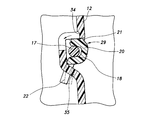
- FIG. 1 Side view of the outer board and inner board viewed from inside the car Side view of the inner board viewed from the outside of the car Light source, light guide member and perspective view of lens Perspective view of the lighting device VII-VII sectional drawing of FIG. 3 VIII-VIII sectional view of FIG. 3
- a cross-sectional view showing a lens before deformation (dotted line) and after deformation of the lens (solid line) when assembling the lens into the board recess (A) locking projections are provided on the outer surface of the second wall, and locking claws are provided on the outer surface of the third wall; and (B) locking claws on the outer surfaces of the second wall and the third wall. Sectional view of another embodiment when is provided
- a door trim 1 (vehicle interior material) is provided so as to cover an inner side surface of a door panel 3 which is a frame member of the door 2 and constitutes an inner wall of a cabin.
- the door panel 3 has an inner panel and an outer panel formed of steel plates.
- the outer panel forms the outer surface of the vehicle body, and the inner panel is disposed on the vehicle compartment side of the outer panel and joined to the outer panel.
- the door trim 1 is formed in a plate shape by a plurality of members made of resin, and is disposed so that the main surfaces of the door panel 3, more specifically, the inner side of the inner panel face in the lateral direction.
- an armrest 4 is formed which bulges inward.
- the armrest 4 extends from the center of the door trim 1 back and forth along the rear edge.
- a lifting device for the window glass and a switch for operating the lighting in the car are provided.
- a speaker grill 5 is provided on the front lower portion of the door trim 1. Behind the speaker grille 5 and below the armrest 4, a door pocket 6 is provided so as to extend in the front-rear direction. The door pocket 6 opens upward and forms a pocket recess 8 which defines a storage space 7.
- the door trim 1 includes a plate-like main board 10 which is a base.
- the peripheral portion of the main board 10 protrudes to the inner panel side and is coupled to the inner panel.
- a gap is formed between the inner panel and the main board 10.
- the main board 10 has a through hole 9 penetrating in the vehicle width direction at a position corresponding to the door pocket 6.
- the door trim 1 is coupled to an outer side surface of the main board 10 and disposed between the main board 10 and the outer board 11 on an outer board 11 covering the through hole 9 from the outer side of the vehicle. And an inner board 12 to be joined.
- the main board 10, the outer board 11 and the inner board 12 constitute a main body (an interior material main body) of the door trim 1.
- the inner board 12 is formed in a plate shape extending back and forth along the lower edge of the through hole 9 of the main board 10 on the side surface inside the main board 10. Are placed along the lower edge of the
- the outer board 11 is formed in a plate shape generally corresponding to the through hole 9 of the main board 10 and the inner board 12. As shown in FIG. 2, the outer board 11 protrudes inward at the peripheral edge, and the center is recessed outward. Predetermined screw holes 13 are formed at the peripheral edge of the outer board 11 and at the front edge, lower edge and rear edge of the inner board 12, and the inner board 12 and the outer board 11 are fastened together to the main board.
- a door pocket 6 is configured by fastening the inner board 12 and the outer board 11 to the main board 10.
- the inner board 12 and the outer board 11 function as pocket members that cooperate with the main board 10 to form a door pocket.
- the inner board 12 forms an inner wall surface of the storage space 7, and the outer board 11 forms an outer wall surface of the storage space 7.
- the front edge of the inner board 12 extends from the gap between the main board 10 and the outer board 11 to the front of the outer board 11.
- the front edge of the inner board 12 is located between the inner panel and the main board 10.
- the inner board 12 is provided with a lighting device 15.
- the lighting device 15 includes a light emitting member 16 including a light source, a light guiding member 17, and a lens 18 that couples the light guiding member 17 to the inner board 12.
- the light emitting member 16 includes a substrate (not shown) provided with the LED element, a lens (not shown) for collecting light from the LED element at a predetermined position, and a holder 19 for housing the substrate and the lens.
- the light emitting member 16 is fastened to the outer wall surface of the front end of the inner board 12 as shown in FIGS. 1 and 4.
- the light emitting member 16 is connected to a predetermined power supply (not shown) mounted on the vehicle body.
- the LED element functions as a light source and is controlled by a switch provided on the armrest 4.
- the holder 19 is provided with a predetermined bolt hole, and the light emitting member 16 is fastened to the inner board 12.
- the light guide member 17 is formed of a highly transparent resin.
- the light guide member 17 is formed in a linear shape (wire shape), and has a circular cross section in a direction orthogonal to the longitudinal direction, that is, a cross section. As shown in FIG. 4, the light guide member 17 extends rearward from the light emitting member 16 along the inner board 12 and reaches the rear end of the inner board 12. One end side of the light guide member 17 is coupled to the light emitting member 16. The light emitted from the LED element is collected by the lens of the light emitting member 16 and is incident on one end side of the light guide member 17 coupled to the light emitting member 16.
- the light guide member 17 propagates the incident light along the longitudinal direction and emits the incident light from the outer peripheral side surface.
- a side-emitting optical fiber cable configured to cause the side surface to emit light by mixing a material that diffusely reflects light into the core material or providing unevenness on the side surface as the light guide member 17 or the like Good.
- the lens 18 is formed of a highly transparent resin that transmits light emitted from the light guide member 17. As shown in FIGS. 5 and 6, the lens 18 includes a lens body 20 extending along the longitudinal direction of the light guide member 17 and a plurality of locking claws 21 (first engaging portions) projecting from the outer surface of the lens body 20. And a plurality of locking projections 22 (second engaging portions).
- the lens body 20 includes a first wall 23 provided along the light guide member 17 and a second wall projecting from both ends of the first wall 23 toward the light guide member 17. And 24 and a third wall 25.
- the first wall 23, the second wall 24, and the third wall 25 form a groove 26 in the lens body 20 that is recessed in a direction perpendicular to the direction in which the lens body 20 extends.
- the lens body 20 has a substantially U-shape opening inward of the vehicle in a cross sectional view.
- the light guide member 17 is accommodated in the groove 26.
- the light guide member 17 is located between the second wall 24 and the third wall 25.
- the first wall 23, the second wall 24, and the third wall 25 respectively extend along the extension direction of the light guide member 17, and the groove 26 is formed along the extension direction of the lens body 20.
- the diameter of the light guide member 17 is set to be slightly larger than the distance between the second wall 24 and the third wall 25, and the light guide member 17 is pressed into the groove 26.
- the light guide member 17 is sandwiched by the second wall 24 and the third wall 25 and coupled to the lens body 20. Light emitted from the side surface of the light guide member 17 is transmitted through the lens body 20 and emitted from the outer surface of the lens 18.
- the locking claw 21 protrudes from the surface of the second wall 24 away from the light guide member 17 (hereinafter referred to as the outer surface of the second wall 24), that is, protrudes from the upper surface, and the like substantially along the extending direction of the lens body 20. It is arranged at intervals.
- the locking claw 21 is formed on an inclined surface 27 which is inclined so as to approach the light guide member 17 in the opening direction of the groove 26 and an end on the side of the inclined surface 27 away from the opening of the groove 26. It has a locking surface 28 generally perpendicular to the outer surface of the two walls 24 and is in the form of a claw.
- the lens 18 is provided with six locking claws 21.
- the locking projections 22 project from the surface of the third wall 25 remote from the light guide member 17 (hereinafter, referred to as the outer surface of the third wall 25), that is, the lower surface, and are approximately equally spaced in the extending direction of the lens body 20. It is arranged.
- the locking projection 22 projects in the direction opposite to the projecting direction of the locking claw 21 in a cross-sectional view of the lens body 20.
- the locking projections 22 each have a plate shape having a main surface parallel to the extending direction of the lens body 20.
- the locking projection 22 is formed at a generally central position between the two adjacent locking claws 21 in the extending direction of the lens body 20. Therefore, the locking claws 21 and the locking projections 22 protrude up and down alternately along the extending direction of the lens body 20, and form a so-called zigzag shape.
- the lens 18 is provided with five locking projections 22.
- the amount of protrusion of the locking claw 21 from the outer surface of the second wall 24 is the amount of protrusion of the locking protrusion 22 from the outer surface of the third wall 25 (L2 in FIG. 6). It is set to be smaller than).
- the locking projection 22 is provided on the end edge of the outer surface of the third wall 25, that is, the end on the groove 26 side. Thereby, the opening edge of the groove 26 can be reinforced to prevent the lens 18 from being damaged.
- the load in the direction in which the second wall 24 and the third wall 25 approach each other causes the lens body 20 to elastically deform so that the second wall 24 and the third wall 25 approach each other.
- FIG. 9 the broken line before deformation of the lens 18 and the solid line after deformation are shown.
- the inner board 12 is formed with a board recess 29 (interior material recess) that is recessed to the outside of the vehicle. As shown in FIG. 4, the board recess 29 extends generally straight rearward from the position where the light emitting member 16 is attached. The lens 18 and the light guide member 17 are accommodated in the board recess 29.
- a board recess 29 internal material recess
- the light guiding member 17 extends from the light emitting member 16 along the board recess 29 between the outer board 11 and the inner board 12 and into the inside of the pocket recess 8.
- the lens 18 extends back and forth along the light guide member 17 inside the pocket recess 8. Light from the LED element reaches the pocket recess 8 through the light guide member 17. As shown in FIG. 2, inside the pocket recess 8, light emitted from the side surface of the light guide member 17 passes through the lens 18 and reaches the storage space 7, and the storage space 7 is illuminated. Therefore, the occupant can easily visually recognize the storage inside the storage space 7.
- the lens 18 is provided along only the light guide member 17 inside the pocket recess 8, but the lens 18 further extends from the light emitting member 16 of the light guide member 17 to the pocket recess 8
- the light guide member 17 may be provided along the light guide member 17.
- a door pocket 6 is formed on the door trim 1 so as to extend forward and backward.
- the board recess 29 is also formed to extend generally back and forth according to the door pocket 6.
- the light guide member 17 is disposed along the extending direction of the door pocket 6. Therefore, the storage space 7 is illuminated lightly back and forth. Further, since the board recess 29 extends in a substantially straight line, when the light guide member 17 is accommodated in the board recess 29, there is no need to bend the light guide member 17, and damage to the light guide member 17 due to bending. Can be prevented.
- the upper surface of the board recess 29 is defined by the upper wall 30, the side on the inner side of the vehicle is defined by the inner wall 31, and the lower surface is defined by the lower wall 32.
- the upper wall 30 and the lower wall 32 face each other.
- the lens 18 is arranged such that the outer surface of the second wall 24 faces upward, the outer surface of the third wall 25 faces downward, the first wall 23 separates from the inner wall 31 of the vehicle, and the opening of the board recess 29 is closed. It is arranged.
- a housing chamber 33 for housing the light guide member 17 is formed by the first wall 23, the second wall 24, the third wall 25, and the inner wall 31.
- the light guide member 17 is surrounded by the first wall 23, the second wall 24, the third wall 25 and the inner wall 31 in the storage chamber 33, and the movement in the vertical direction and the vehicle width direction is restricted.
- the upward movement of the lens body 20 is restricted by the upper wall 30, and the downward movement of the lens body 20 is restricted by the lower wall 32.
- the opposing wall surfaces of the upper wall 30 and the lower wall 32 respectively abut the second wall 24 against the upper wall 30 when the lens body 20 is accommodated in the board recess 29, and the third wall 25 abuts on the lower wall 32. Preferably, they are set to be in contact with each other.
- the second wall 24 abuts on the upper wall 30 and the third wall 25 abuts on the lower wall 32, so that the lens 18 does not easily come off the board recess 29.
- First receiving holes 34 (first engaged portions) penetrating in the vertical direction are formed at positions corresponding to the respective locking claws 21 in the upper wall 30.
- second receiving holes 35 (second engaged portions) penetrating vertically are formed.
- the inner board 12 is formed with six first receiving holes 34 and five second receiving holes 35.
- the locking claw 21 is fitted in the first receiving hole 34.
- the locking claw 21 is inserted into the first receiving hole 34, and the locking surface 28 of the locking claw 21 abuts on the wall surface defining the first receiving hole 34, and the movement of the upper part of the lens 18 in the vehicle width direction is restricted. It is done.
- the locking projection 22 is inserted into the second receiving hole 35. Movement of the lower portion of the lens 18 in the vehicle width direction is restricted by the engagement between the locking projection 22 and the second receiving hole 35. Since the locking projection 22 penetrates the second receiving hole 35, the movement of the lower portion of the lens 18 in the vehicle width direction is more reliably restricted.
- the first receiving hole 34 extends to the top of the upper wall 30 and the inner side wall 31.
- the second receiving hole 35 extends to the lower portion of the lower wall 32 and the inner wall 31 of the vehicle. Therefore, the locking claw 21 can be easily fitted into the first receiving hole 34, and the locking projection 22 can be easily inserted into the second receiving hole 35.
- the upper wall 30 and the lower wall 32 restrict the vertical movement of the lens body 20. Due to these restrictions, the lens 18 is coupled to the inner board 12, and the light guide member 17 is coupled to the inner board 12 via the lens 18.
- the width of the second receiving hole 35 in the extension direction of the board recess 29 is set to be substantially equal to the width in the extension direction of the lens body 20 of the locking projection 22 and slightly larger than the width of the locking projection 22 ing.
- the front and rear walls defining the second receiving hole 35 restrict the movement of the locking projection 22 in the front-rear direction, so the movement of the lens 18 in the direction along the extending direction of the board recess 29 is restricted. Thereby, the lens 18 can be more firmly coupled to the inner board 12.
- the upper wall 30 is substantially horizontal and has a main surface that is generally in the vertical direction. Therefore, the light emitted upward from the lens 18 is blocked by the upper wall 30.
- the lower wall 32 is inclined downward toward the inside of the pocket recess 8. Therefore, the light emitted downward from the lens 18 reaches the storage space 7 without being blocked by the lower wall 32. Since the light emitted from the lens 18 does not reach the eyes of the occupant directly, the occupant can easily view the inside of the storage space 7.
- the locking projection 22 is inserted into the second receiving hole 35.
- the lens body 20 is pushed into the board recess 29.
- the inclined surface 27 is pressed by the upper wall 30, and a load directed downward is applied to the second wall 24.
- a load directed upward from the lower wall 32 is applied to the third wall 25, and these loads elastically deform the lens body 20. Due to the elastic deformation of the lens body 20, the locking claw 21 moves to the third wall 25 side.
- the lens 18 can be pivoted in the direction in which the lens body 20 moves into the inside of the board recess 29 with the lower end of the lens body 20 as an axis.
- the lens main body 20 is elastically deformed so that the distance between the second wall 24 and the third wall 25 becomes smaller by about the amount of protrusion of the locking claw 21 before the deformation, the lens main body 20 becomes a board concave portion 29. It can be inserted into Therefore, since the amount of protrusion of the locking claw 21 from the outer surface of the second wall 24 is smaller than that of the locking protrusion 22, the amount of deformation of the lens body 20 required for assembly can be reduced, and assembly is easy. is there.
- the locking claw 21 is fitted in the first receiving hole 34, and the assembly is completed.
- the assembly is completed by inserting the lens body 20 into the board recess 29, the assembly is easy. Since the inclined surface 27 is formed on the locking projection 22, the lens body 20 is easily deformed, and the lens body 20 can be easily inserted into the board recess 29.
- the effect of the door trim 1 will be described.
- the locking projection 22 is inserted into the second receiving hole 35, and the lens body 20 is elastically deformed to lock the locking claw 21 in the first receiving hole 34.
- the assembly of the light guide member 17 and the lens 18 to the inner board 12 is completed. Therefore, assembly is easy. Also, by changing the arrangement of the first receiving hole 34 and the second receiving hole 35, the light guide member 17 and the lens 18 can be coupled to a desired position of the inner board 12. Therefore, the degree of freedom in the arrangement of the light guide member 17 and the lens 18 is improved.
- the lens 18 is coupled to the inner board 12 through locking claws 21 and locking projections 22 formed on the upper and lower surfaces of the lens body 20.
- the locking claws 21 and the locking projections 22 project in mutually opposite directions.
- the lens body 20 is coupled to the inner board 12 at its upper and lower portions, so the coupling between the lens 18 and the inner board 12 is strong. Therefore, even when the occupant touches the lens 18, it is possible to prevent the lens 18 from coming off the inner board 12.
- the lens 18 is accommodated in the board recess 29 and does not protrude from the outer wall of the inner board 12 toward the inside of the pocket recess 8. Therefore, it becomes difficult for the passenger's hand to touch the lens 18, and the lens 18 can be prevented from coming off the inner board 12.
- the light guide member 17 is covered by the lens body 20 from above and below, and from the vehicle outside, and is surrounded by the lens 18 and the wall of the vehicle outside of the inner board 12. Not exposed Therefore, the light guide member 17 is protected by the lens body 20, and the light guide member 17 becomes more difficult to break. Furthermore, the light guide member 17 is less likely to be contaminated, and stable illumination can be realized.
- a plurality of locking projections 22 project parallel to one another on the outer surface of the third wall 25. Therefore, the locking projection 22 can be easily fitted into the second receiving hole 35. Further, the lens body 20 is reinforced by providing the locking claws 21 and the locking projections 22 on the lens body 20, and the lens 18 is less likely to be damaged.
- the light guide member 17 is press-fit and held in the groove portion 26, there is no need to provide a locking portion or the like in the light guide member 17, and the coupling structure of the light guide member 17 and the lens 18 is simple.
- the locking claws 21 and the locking protrusions 22 protrude alternately along the extension direction of the lens 18. Therefore, compared with the aspect in which the locking claws 21 and the locking protrusions 22 project vertically at the same position in the extending direction of the lens body 20, the locking claws 21 and the locking protrusions 22 correspond to the corresponding first receiving holes 34 or The lens 18 can be easily assembled since it can be connected to the second receiving hole 35 in order from the end. Further, since the lens 18 is coupled to the inner board 12 in order along the extension direction, the coupling between the lens 18 and the inner board 12 can be strengthened.
- first receiving hole 34 and the second receiving hole 35 are formed as through holes for receiving the locking claws 21 and the locking projections 22, respectively, they are received and engaged with the locking claws 21 and the locking projections 22. As long as it is an aspect which forms the recessed part to be carried out, it may be any aspect.
- the locking projections 22 may be provided on the outer surface of the second wall 24 of the lens body 20, and the locking claws 21 may be provided on the outer surface of the third wall 25 of the lens body 20. At this time, the locking projection 22 is inserted into the first receiving hole 34, and the locking claw 21 engages with the second receiving hole 35.
- locking claws 50 are respectively provided on the outer surfaces of the second wall 24 and the third wall 25 of the lens body 20, and they are engaged with the first receiving hole 34 and the second receiving hole 35, respectively. It may be configured to
- the light guide member 17 is press-fit into the groove 26, but when the lens body 20 is accommodated in the board recess 29, the light guide member 17 is not inserted from the upper wall 30 and the lower wall 32 of the board recess 29.
- a pressure may be applied to the second wall 24 and the third wall 25 in a direction toward the light guide member 17, and the pressure may cause the second wall 24 and the third wall 25 to sandwich the light guide member 17.
- the optical fiber may be prevented from coming off from the groove 26.
- the light guide member 17 and the lens 18 are provided on the inner board 12, but may be provided on the outer board 11. Further, when the pocket board for forming the door pocket 6 is attached without providing the through hole 9 in the main board 10, the light guiding member 17 and the lens 18 are provided in either the main board 10 or the pocket board. It may be done.
- the lighting device 15 illuminates the storage space 7 of the door pocket 6, but may be provided on any member of the member constituting the vehicle compartment, for example, to illuminate a switch provided on the armrest, or It may be configured to illuminate an occupant's foot when opening and closing the door.
- this invention was applied to the door trim 1, you may be applied to the member which comprises a center console and a dashboard.
- Door trim (vehicle interior material) 2: Door 3: Door panel 6: Door pocket 10: Main board 11: Outer board (pocket member) 12: Inner board (pocket member) 17: light guide member 18: lens 19: holder 21: locking claw (first engaging portion) 22: Locking projection (second engaging portion) 23: first wall 24: second wall 25: third wall 26: groove portion 29: board recess (interior material recess) 30: upper wall 31: inner wall 32: lower wall 34: first receiving hole (first engaged portion) 35: Second receiving hole (second engaged portion)
Landscapes
- Engineering & Computer Science (AREA)
- Mechanical Engineering (AREA)
- General Engineering & Computer Science (AREA)
- Physics & Mathematics (AREA)
- General Physics & Mathematics (AREA)
- Optics & Photonics (AREA)
- Arrangements Of Lighting Devices For Vehicle Interiors, Mounting And Supporting Thereof, Circuits Therefore (AREA)
- Securing Globes, Refractors, Reflectors Or The Like (AREA)
- Vehicle Interior And Exterior Ornaments, Soundproofing, And Insulation (AREA)
Priority Applications (5)
| Application Number | Priority Date | Filing Date | Title |
|---|---|---|---|
| US16/652,184 US11110858B2 (en) | 2017-10-02 | 2018-09-28 | Vehicle interior member |
| CN201880062370.4A CN111132873B (zh) | 2017-10-02 | 2018-09-28 | 车辆用内饰件 |
| EP18864096.5A EP3693221B1 (en) | 2017-10-02 | 2018-09-28 | Interior decorating material for vehicle |
| US17/399,256 US11654826B2 (en) | 2017-10-02 | 2021-08-11 | Vehicle interior member |
| US18/303,816 US11987179B2 (en) | 2017-10-02 | 2023-04-20 | Vehicle interior member |
Applications Claiming Priority (2)
| Application Number | Priority Date | Filing Date | Title |
|---|---|---|---|
| JP2017192976A JP6952224B2 (ja) | 2017-10-02 | 2017-10-02 | 車両用内装材 |
| JP2017-192976 | 2017-10-02 |
Related Child Applications (2)
| Application Number | Title | Priority Date | Filing Date |
|---|---|---|---|
| US16/652,184 A-371-Of-International US11110858B2 (en) | 2017-10-02 | 2018-09-28 | Vehicle interior member |
| US17/399,256 Continuation US11654826B2 (en) | 2017-10-02 | 2021-08-11 | Vehicle interior member |
Publications (1)
| Publication Number | Publication Date |
|---|---|
| WO2019069820A1 true WO2019069820A1 (ja) | 2019-04-11 |
Family
ID=65994631
Family Applications (1)
| Application Number | Title | Priority Date | Filing Date |
|---|---|---|---|
| PCT/JP2018/036360 Ceased WO2019069820A1 (ja) | 2017-10-02 | 2018-09-28 | 車両用内装材 |
Country Status (5)
| Country | Link |
|---|---|
| US (3) | US11110858B2 (https=) |
| EP (1) | EP3693221B1 (https=) |
| JP (3) | JP6952224B2 (https=) |
| CN (1) | CN111132873B (https=) |
| WO (1) | WO2019069820A1 (https=) |
Families Citing this family (10)
| Publication number | Priority date | Publication date | Assignee | Title |
|---|---|---|---|---|
| JP7169549B2 (ja) * | 2019-09-26 | 2022-11-11 | いすゞ自動車株式会社 | 車両用照明装置 |
| US11608008B2 (en) * | 2019-09-30 | 2023-03-21 | Honda Motor Co., Ltd. | Illuminated speaker panel assembly with integrated audio seal |
| JP7415819B2 (ja) * | 2020-06-25 | 2024-01-17 | トヨタ紡織株式会社 | 照明装置の取付構造および照明装置付内装材 |
| US11608005B2 (en) * | 2020-09-16 | 2023-03-21 | Ford Global Technologies, Llc | Vehicle door pocket |
| CN114321765B (zh) * | 2020-10-12 | 2023-11-24 | 丰田纺织株式会社 | 包括照明装置和运输工具内部部件的安装组件 |
| WO2022093143A1 (en) * | 2020-11-11 | 2022-05-05 | İNAN, İlker | Illuminated decorative exterior trim for vehicles |
| JP2023017261A (ja) * | 2021-07-26 | 2023-02-07 | トヨタ自動車株式会社 | 車両前部構造 |
| CN113734063B (zh) * | 2021-08-31 | 2022-11-25 | 东风柳州汽车有限公司 | 轻量化多层复合材料重卡车门装饰板 |
| KR102766636B1 (ko) * | 2023-04-24 | 2025-02-12 | 주식회사 서연이화 | 차량의 도어트림 |
| CN117022137A (zh) * | 2023-07-03 | 2023-11-10 | 江阴市羽项汽车饰件有限公司 | 一种可透光双料注塑内饰条 |
Citations (6)
| Publication number | Priority date | Publication date | Assignee | Title |
|---|---|---|---|---|
| JP2008162296A (ja) * | 2006-12-26 | 2008-07-17 | Ichikoh Ind Ltd | 車両用灯具 |
| JP2009078794A (ja) * | 2007-09-06 | 2009-04-16 | Toyoda Gosei Co Ltd | 車両用室内照明装置 |
| JP2014133459A (ja) * | 2013-01-09 | 2014-07-24 | Toyota Boshoku Corp | 車両用内装材 |
| JP2015155298A (ja) | 2015-03-19 | 2015-08-27 | 本田技研工業株式会社 | 車両用内装材 |
| JP2015216005A (ja) * | 2014-05-09 | 2015-12-03 | 林テレンプ株式会社 | 導光体 |
| JP2016055668A (ja) * | 2014-09-05 | 2016-04-21 | 林テレンプ株式会社 | 照明装置 |
Family Cites Families (27)
| Publication number | Priority date | Publication date | Assignee | Title |
|---|---|---|---|---|
| US20090073708A1 (en) | 2007-09-06 | 2009-03-19 | Toyoda Gosei Co., Ltd. | Vehicle interior illumination system |
| JP2009126313A (ja) * | 2007-11-22 | 2009-06-11 | Aisin Seiki Co Ltd | 車両用モール |
| JP5096967B2 (ja) | 2008-03-07 | 2012-12-12 | 矢崎総業株式会社 | 車室内照明装置用ケース |
| GB0813186D0 (en) | 2008-07-18 | 2008-08-27 | 3M Innovative Properties Co | Lighting device comprising a light guide and a support |
| JP4969544B2 (ja) * | 2008-09-19 | 2012-07-04 | 本田技研工業株式会社 | 照明部材及びそれを用いたドアライニング |
| US20110002138A1 (en) * | 2009-07-02 | 2011-01-06 | International Automotive Components Group North America, Inc. | Selectively illuminated trim panels |
| ITTV20110034A1 (it) * | 2011-03-04 | 2012-09-05 | Automotive Lighting Italia Spa | Fanale automobilistico |
| DE102011111209A1 (de) * | 2011-08-20 | 2013-02-21 | Brose Fahrzeugteile Gmbh & Co. Kommanditgesellschaft, Hallstadt | Türmodul mit integrierter Sensorelektrode |
| DE102011112320B3 (de) * | 2011-09-02 | 2012-08-02 | Audi Ag | Umlaufende Beleuchtungsvorrichtung für eine Fahrzeug-Komponente |
| JP5794095B2 (ja) * | 2011-10-13 | 2015-10-14 | トヨタ紡織株式会社 | 光源ユニットの取付構造 |
| JP5988254B2 (ja) * | 2012-08-03 | 2016-09-07 | パナソニックIpマネジメント株式会社 | 棚板装置 |
| JP5942168B2 (ja) * | 2012-08-03 | 2016-06-29 | パナソニックIpマネジメント株式会社 | 照明装置 |
| JP5718956B2 (ja) * | 2013-01-24 | 2015-05-13 | 本田技研工業株式会社 | 車両用内装材 |
| US9254785B2 (en) * | 2013-02-14 | 2016-02-09 | Ford Global Technologies, Llc | Extruded light pipe carrier |
| JP6257173B2 (ja) * | 2013-05-29 | 2018-01-10 | テイ・エス テック株式会社 | 車両用加飾部材 |
| JP6003830B2 (ja) * | 2013-06-28 | 2016-10-05 | トヨタ紡織株式会社 | 照明装置 |
| JP6146201B2 (ja) | 2013-08-21 | 2017-06-14 | トヨタ紡織株式会社 | 車両用ドアトリム |
| DE202013008321U1 (de) * | 2013-09-19 | 2013-10-02 | Kunststoff-Technik Scherer & Trier Gmbh & Co. Kg | Abdeckungseinrichtung, System, Karosseriebauteil, Karosseriebauteilsystem und Fahrzeug |
| US9376057B2 (en) * | 2014-02-27 | 2016-06-28 | Nissan North America, Inc. | Lighting structure |
| JP5721020B2 (ja) * | 2014-04-08 | 2015-05-20 | トヨタ紡織株式会社 | 車両室内照明装置 |
| JP6342241B2 (ja) * | 2014-07-09 | 2018-06-13 | 林テレンプ株式会社 | 照明装置 |
| JP2016043729A (ja) | 2014-08-20 | 2016-04-04 | 河西工業株式会社 | 照明装置及び車両室内用照明装置 |
| US20160107566A1 (en) | 2014-10-20 | 2016-04-21 | Nissan North America, Inc. | Vehicle interior lighting structure |
| DE102014019607A1 (de) * | 2014-12-30 | 2016-06-30 | Audi Ag | Zierteil für ein Kraftfahrzeug |
| JP6432835B2 (ja) * | 2015-02-20 | 2018-12-05 | パナソニックIpマネジメント株式会社 | 照明装置、および照明装置の設置構造 |
| JP2017095046A (ja) | 2015-11-27 | 2017-06-01 | トヨタ紡織株式会社 | 車両用照明装置 |
| EP3196550B1 (en) * | 2016-01-20 | 2018-10-24 | OSRAM GmbH | A method of producing lighting devices and corresponding lighting device |
-
2017
- 2017-10-02 JP JP2017192976A patent/JP6952224B2/ja active Active
-
2018
- 2018-09-28 CN CN201880062370.4A patent/CN111132873B/zh active Active
- 2018-09-28 EP EP18864096.5A patent/EP3693221B1/en active Active
- 2018-09-28 US US16/652,184 patent/US11110858B2/en active Active
- 2018-09-28 WO PCT/JP2018/036360 patent/WO2019069820A1/ja not_active Ceased
-
2021
- 2021-08-11 JP JP2021131068A patent/JP7256419B2/ja active Active
- 2021-08-11 US US17/399,256 patent/US11654826B2/en active Active
-
2023
- 2023-03-23 JP JP2023046879A patent/JP7492171B2/ja active Active
- 2023-04-20 US US18/303,816 patent/US11987179B2/en active Active
Patent Citations (6)
| Publication number | Priority date | Publication date | Assignee | Title |
|---|---|---|---|---|
| JP2008162296A (ja) * | 2006-12-26 | 2008-07-17 | Ichikoh Ind Ltd | 車両用灯具 |
| JP2009078794A (ja) * | 2007-09-06 | 2009-04-16 | Toyoda Gosei Co Ltd | 車両用室内照明装置 |
| JP2014133459A (ja) * | 2013-01-09 | 2014-07-24 | Toyota Boshoku Corp | 車両用内装材 |
| JP2015216005A (ja) * | 2014-05-09 | 2015-12-03 | 林テレンプ株式会社 | 導光体 |
| JP2016055668A (ja) * | 2014-09-05 | 2016-04-21 | 林テレンプ株式会社 | 照明装置 |
| JP2015155298A (ja) | 2015-03-19 | 2015-08-27 | 本田技研工業株式会社 | 車両用内装材 |
Also Published As
| Publication number | Publication date |
|---|---|
| US20200317122A1 (en) | 2020-10-08 |
| US11654826B2 (en) | 2023-05-23 |
| EP3693221A4 (en) | 2021-04-14 |
| CN111132873B (zh) | 2023-08-01 |
| JP7256419B2 (ja) | 2023-04-12 |
| EP3693221B1 (en) | 2023-10-25 |
| US20230339391A1 (en) | 2023-10-26 |
| JP2021185077A (ja) | 2021-12-09 |
| JP6952224B2 (ja) | 2021-10-20 |
| JP7492171B2 (ja) | 2024-05-29 |
| JP2019064491A (ja) | 2019-04-25 |
| US20220024379A1 (en) | 2022-01-27 |
| US11110858B2 (en) | 2021-09-07 |
| EP3693221A1 (en) | 2020-08-12 |
| US11987179B2 (en) | 2024-05-21 |
| JP2023075355A (ja) | 2023-05-30 |
| CN111132873A (zh) | 2020-05-08 |
Similar Documents
| Publication | Publication Date | Title |
|---|---|---|
| JP7492171B2 (ja) | 車両用内装材 | |
| CN106604845B (zh) | 车辆室内照明装置 | |
| JP6439583B2 (ja) | 車両用照明装置 | |
| JP6445431B2 (ja) | 車両用ドアライニング及びその取付構造 | |
| CN107035996B (zh) | 交通工具用照明装置 | |
| JP6470962B2 (ja) | 照明装置の取付構造、車両用内装部品及びドアパネル | |
| JP5450036B2 (ja) | 車両用照明装置 | |
| JP5246930B2 (ja) | ドアミラー用のターンランプ | |
| JP6652720B2 (ja) | ランプユニット、及び車両用ドア | |
| WO2021060291A1 (ja) | 車両用照明装置 | |
| JP5450035B2 (ja) | 車両用照明装置 | |
| WO2020049931A1 (ja) | 車両用照明装置および車両用ドア | |
| JP2024111386A (ja) | 乗物用照明構造 | |
| CN221497831U (zh) | 交通工具用照明构造 | |
| JP2010137681A (ja) | 車両用ドア構造 | |
| JP2022007077A (ja) | 照明装置の取付構造および照明装置付内装材 | |
| JP2019189151A (ja) | 乗物用照明装置 | |
| JP6766630B2 (ja) | 乗物用内装材 | |
| JP2010269653A (ja) | 照明装置の取付構造及び照明装置の取付方法 | |
| KR20210134420A (ko) | 램프 유닛, 및 램프 유닛을 구비한 차량용 도어 | |
| JP6786725B2 (ja) | 車両室内用照明装置 | |
| JP2024087944A (ja) | 乗物用照明装置 | |
| JP2024087943A (ja) | 乗物照明構造 |
Legal Events
| Date | Code | Title | Description |
|---|---|---|---|
| 121 | Ep: the epo has been informed by wipo that ep was designated in this application |
Ref document number: 18864096 Country of ref document: EP Kind code of ref document: A1 |
|
| NENP | Non-entry into the national phase |
Ref country code: DE |
|
| ENP | Entry into the national phase |
Ref document number: 2018864096 Country of ref document: EP Effective date: 20200504 |