WO2019065951A1 - 電解コンデンサ - Google Patents
電解コンデンサ Download PDFInfo
- Publication number
- WO2019065951A1 WO2019065951A1 PCT/JP2018/036209 JP2018036209W WO2019065951A1 WO 2019065951 A1 WO2019065951 A1 WO 2019065951A1 JP 2018036209 W JP2018036209 W JP 2018036209W WO 2019065951 A1 WO2019065951 A1 WO 2019065951A1
- Authority
- WO
- WIPO (PCT)
- Prior art keywords
- acid
- mass
- electrolytic capacitor
- chemical conversion
- component
- Prior art date
- Legal status (The legal status is an assumption and is not a legal conclusion. Google has not performed a legal analysis and makes no representation as to the accuracy of the status listed.)
- Ceased
Links
Images

Classifications
-
- H—ELECTRICITY
- H01—ELECTRIC ELEMENTS
- H01G—CAPACITORS; CAPACITORS, RECTIFIERS, DETECTORS, SWITCHING DEVICES, LIGHT-SENSITIVE OR TEMPERATURE-SENSITIVE DEVICES OF THE ELECTROLYTIC TYPE
- H01G9/00—Electrolytic capacitors, rectifiers, detectors, switching devices, light-sensitive or temperature-sensitive devices; Processes of their manufacture
- H01G9/004—Details
- H01G9/022—Electrolytes; Absorbents
- H01G9/025—Solid electrolytes
- H01G9/028—Organic semiconducting electrolytes, e.g. TCNQ
-
- H—ELECTRICITY
- H01—ELECTRIC ELEMENTS
- H01G—CAPACITORS; CAPACITORS, RECTIFIERS, DETECTORS, SWITCHING DEVICES, LIGHT-SENSITIVE OR TEMPERATURE-SENSITIVE DEVICES OF THE ELECTROLYTIC TYPE
- H01G9/00—Electrolytic capacitors, rectifiers, detectors, switching devices, light-sensitive or temperature-sensitive devices; Processes of their manufacture
- H01G9/004—Details
- H01G9/022—Electrolytes; Absorbents
- H01G9/035—Liquid electrolytes, e.g. impregnating materials
-
- H—ELECTRICITY
- H01—ELECTRIC ELEMENTS
- H01G—CAPACITORS; CAPACITORS, RECTIFIERS, DETECTORS, SWITCHING DEVICES, LIGHT-SENSITIVE OR TEMPERATURE-SENSITIVE DEVICES OF THE ELECTROLYTIC TYPE
- H01G9/00—Electrolytic capacitors, rectifiers, detectors, switching devices, light-sensitive or temperature-sensitive devices; Processes of their manufacture
- H01G9/145—Liquid electrolytic capacitors
-
- H—ELECTRICITY
- H01—ELECTRIC ELEMENTS
- H01G—CAPACITORS; CAPACITORS, RECTIFIERS, DETECTORS, SWITCHING DEVICES, LIGHT-SENSITIVE OR TEMPERATURE-SENSITIVE DEVICES OF THE ELECTROLYTIC TYPE
- H01G9/00—Electrolytic capacitors, rectifiers, detectors, switching devices, light-sensitive or temperature-sensitive devices; Processes of their manufacture
- H01G9/15—Solid electrolytic capacitors
- H01G9/151—Solid electrolytic capacitors with wound foil electrodes
-
- H—ELECTRICITY
- H01—ELECTRIC ELEMENTS
- H01G—CAPACITORS; CAPACITORS, RECTIFIERS, DETECTORS, SWITCHING DEVICES, LIGHT-SENSITIVE OR TEMPERATURE-SENSITIVE DEVICES OF THE ELECTROLYTIC TYPE
- H01G9/00—Electrolytic capacitors, rectifiers, detectors, switching devices, light-sensitive or temperature-sensitive devices; Processes of their manufacture
- H01G9/004—Details
- H01G9/022—Electrolytes; Absorbents
-
- H—ELECTRICITY
- H01—ELECTRIC ELEMENTS
- H01G—CAPACITORS; CAPACITORS, RECTIFIERS, DETECTORS, SWITCHING DEVICES, LIGHT-SENSITIVE OR TEMPERATURE-SENSITIVE DEVICES OF THE ELECTROLYTIC TYPE
- H01G9/00—Electrolytic capacitors, rectifiers, detectors, switching devices, light-sensitive or temperature-sensitive devices; Processes of their manufacture
- H01G9/004—Details
- H01G9/04—Electrodes or formation of dielectric layers thereon
- H01G9/042—Electrodes or formation of dielectric layers thereon characterised by the material
-
- Y—GENERAL TAGGING OF NEW TECHNOLOGICAL DEVELOPMENTS; GENERAL TAGGING OF CROSS-SECTIONAL TECHNOLOGIES SPANNING OVER SEVERAL SECTIONS OF THE IPC; TECHNICAL SUBJECTS COVERED BY FORMER USPC CROSS-REFERENCE ART COLLECTIONS [XRACs] AND DIGESTS
- Y02—TECHNOLOGIES OR APPLICATIONS FOR MITIGATION OR ADAPTATION AGAINST CLIMATE CHANGE
- Y02E—REDUCTION OF GREENHOUSE GAS [GHG] EMISSIONS, RELATED TO ENERGY GENERATION, TRANSMISSION OR DISTRIBUTION
- Y02E60/00—Enabling technologies; Technologies with a potential or indirect contribution to GHG emissions mitigation
- Y02E60/13—Energy storage using capacitors
Definitions
- the present invention relates to an electrolytic capacitor comprising a solid electrolyte and an electrolytic solution.
- Patent Document 1 discloses a hybrid electrolytic capacitor in which an oxide film (chemical conversion film) is formed on the surface of an anode body.
- the first aspect of the present invention is an electrolytic capacitor comprising a capacitor element and an electrolytic solution, wherein the capacitor element is an anode body having a chemical conversion film, and a solid electrolyte in contact with the chemical conversion film.
- the electrolyte contains a solvent and a solute, and the solvent contains at least one selected from the group consisting of lactone compounds, glycol compounds and sulfone compounds, and the solute contains a first acid component.
- the ratio of the formation voltage V volts applied to the anode body to form the conversion coating and the rated voltage Vw of the electrolytic capacitor V / Vw is 1.7 or less, on the electrolytic capacitor.
- a second aspect of the present invention is an electrolytic capacitor comprising a capacitor element and an electrolytic solution, wherein the capacitor element comprises an anode body having a chemical conversion film, and a solid electrolyte in contact with the chemical conversion film.
- the electrolyte includes a solvent and a solute, and the solvent includes at least one selected from the group consisting of a lactone compound, a glycol compound and a sulfone compound, and the solute is an organic acid as a first acid component.
- the electrolytic capacitor according to the present embodiment includes a capacitor element and an electrolytic solution.
- the capacitor element includes an anode body having a chemical conversion film and a solid electrolyte in contact with the chemical conversion film.
- the solid electrolyte and the chemical conversion film are in contact with each other. Therefore, in order to reduce the leak current, conventionally, the formation voltage V is set to a high value about twice the rated voltage Vw of the electrolytic capacitor to form a chemical conversion film having a sufficient thickness. Therefore, it is difficult to increase the capacitance of the electrolytic capacitor or to miniaturize the electrolytic capacitor by reducing the ratio (V / Vw) between the rated voltage Vw and the formation voltage V in the hybrid electrolytic capacitor. Met.
- a solute containing at least one of benzenedicarboxylic acid and its derivative as a first acid component and at least one of an amine and an amidine as a base component is used.
- concentration of the sum total of the acid component containing a 1st acid component, and a base component is 15 mass% or more and less than 40 mass%.
- a specific solvent is used. Specifically, at least one selected from the group consisting of ⁇ -butyrolactone, ethylene glycol and sulfolane is used as the solvent.
- the electrolytic solution into the composition as described above By making the electrolytic solution into the composition as described above, the first acid component contained in the solute can easily reach the vicinity of the defect of the anode body. Therefore, the self-repairing performance of the chemical conversion film is improved, and the capacitance and ESR can be maintained. Accordingly, the ratio V / Vw of the formation voltage V volts to the rated voltage Vw volts can be made 1.7 or less.
- the concentration of the polymer component is 1% by mass or more and 15% by mass or less.
- the chemical conversion film is not limited to a film formed by a method (hereinafter, the first method) of applying a predetermined formation voltage to the anode body in a state of being immersed in an acidic aqueous solution (hereinafter, a chemical conversion solution).
- the chemical conversion film may be formed by heat treatment of the anode body in a state of being immersed in the chemical conversion solution (hereinafter, the second method).
- the chemical conversion film is formed by the first method, a chemical conversion film having a thickness T in accordance with the formation voltage is formed. That is, the formation voltage is obtained from the thickness T of the chemical conversion film.
- the formation voltage necessary for forming the chemical conversion film by the first method can be determined from the thickness T thereof. That is, the chemical conversion voltage V includes the voltage applied to the anode body to form a chemical conversion film of thickness T, and the voltage necessary to form a chemical conversion film of thickness T.
- the rated voltage Vw is the upper limit voltage defined as the rating, and is the maximum value of the voltage applied between the electrodes of the electrolytic capacitor.
- the electrolyte solution contains a solvent and a solute.
- the pH of the electrolyte is preferably 4.5 or less. By setting the pH of the electrolytic solution to 4.5 or less, the dedoping phenomenon of the solid electrolyte is easily suppressed. Therefore, ESR can be maintained.
- the pH of the electrolytic solution is more preferably 4 or less, and particularly preferably 3.8 or less.
- the pH of the electrolyte is preferably 2 or more.
- the conductivity of the electrolytic solution is preferably 0.01 mS / cm or more and 3 mS / cm or less. In this case, when the ratio of the formation voltage V volts to the rated voltage Vw volts: V / Vw is 1.7 or less, the self-repairing performance can be further improved.
- the solvent preferably contains at least one selected from the group consisting of ⁇ -butyrolactone ( ⁇ BL), ethylene glycol (EG) and sulfolane (SL) (hereinafter referred to as the main solvent).
- ⁇ BL ⁇ -butyrolactone
- EG ethylene glycol
- SL sulfolane
- glycol compounds other than EG glycol compounds other than SL
- lactone compounds other than ⁇ BL may be used.
- glycol compounds other than EG diethylene glycol, triethylene glycol, propylene glycol and the like can be used.
- sulfone compounds other than SL dimethylsulfoxide, diethylsulfoxide and the like can be used.
- lactone compound other than ⁇ BL ⁇ -valerolactone can be used. 50 mass% or more is preferable, as for the ratio of the main solvent (for example, total of (gamma) BL, EG, and SL) contained in a solvent, 60 mass% or more is more preferable, and 70 mass% or more is more preferable.
- the solvent can contain a carbonate compound, a monohydric or trihydric or higher alcohol, and the like as a solvent other than the main solvent (hereinafter, a co-solvent).
- a carbonate compound dimethyl carbonate (DMC), diethyl carbonate (DEC), ethyl methyl carbonate (EMC), ethylene carbonate (EC), propylene carbonate (PC), fluoro ethylene carbonate (FEC), etc.
- DMC dimethyl carbonate
- DEC diethyl carbonate
- EMC ethyl methyl carbonate
- EMC ethylene carbonate
- PC propylene carbonate
- FEC fluoro ethylene carbonate
- glycerin or polyglycerin can be used as the alcohol. These may be used alone or in combination of two or more.
- the concentration of the solute is 15% by mass or more and 40% by mass or less.
- the concentration of the solute is more preferably 20% by mass or more and 40% by mass or less, and particularly preferably 20%
- the concentration of the solute is the sum of the concentration of the acid component and the concentration of the base component.
- the acid component includes a first acid component and a second acid component other than the first acid component.
- the base component includes an amine and / or an amidine (hereinafter, first base component), and a second base component other than the first base component.
- the solute contains at least one of benzenedicarboxylic acid and its derivative as a first acid component.
- the benzenedicarboxylic acid may be o-phthalic acid, m-phthalic acid or p-phthalic acid.
- Examples of derivatives of benzenedicarboxylic acid include 3-sulfophthalic acid having a sulfo group, 3,5-disulfophthalic acid, 4-sulfoisophthalic acid, 2-sulfoterephthalic acid, 2-methyl-5-sulfoterephthalic acid and the like. Be Among these, o-phthalic acid is preferred.
- the concentration of the first acid component contained in the electrolytic solution is preferably 5% by mass or more, and more preferably 15% by mass or more, from the viewpoint of easy dissociation. Moreover, 35 mass% or less is preferable, and, as for the density
- the acid component may contain a second acid component other than the first acid component.
- organic acid used as the second acid component examples include polycarboxylic acids, monocarboxylic acids and polyhydric phenols.
- polycarboxylic acids examples include aliphatic polycarboxylic acids: ([saturated polycarboxylic acids such as oxalic acid, malonic acid, succinic acid, glutaric acid, adipic acid, pimelic acid, suberic acid, azelaic acid, sebacic acid, 1, 6 -Decanedicarboxylic acid, 5,6-decanedicarboxylic acid], [unsaturated polycarboxylic acid such as maleic acid, fumaric acid, icotanic acid], aromatic polycarboxylic acid: (eg trimellitic acid, pyromellitic acid), Alicyclic polycarboxylic acids: (eg, cyclohexane-1,2-dicarboxylic acid, cyclohexene-1,2-dicarboxylic acid, etc.).
- saturated polycarboxylic acids such as oxalic acid, malonic acid, succinic acid, glutaric acid, adipic acid, pimelic acid
- monocarboxylic acids include aliphatic monocarboxylic acids (having 1 to 30 carbon atoms): ([saturated monocarboxylic acids such as formic acid, acetic acid, propionic acid, butyric acid, isobutyric acid, valeric acid, caproic acid, enanthate, caprylic acid , Pelargonic acid, lauric acid, myristic acid, stearic acid, behenic acid], [unsaturated monocarboxylic acid such as acrylic acid, methacrylic acid, oleic acid], aromatic monocarboxylic acid: (such as benzoic acid, cinnamic acid , Naphthoic acid, oxycarboxylic acid: (for example, salicylic acid, mandelic acid, resorcinic acid), among them, preferable among these are maleic acid, benzoic acid, pyromellitic acid, resorcynic acid, which has high conductivity and is thermally stable. It
- polyhydric phenols examples include catechol, resorcinol, hydroquinone, pyrogallol, phloroglucin and the like.
- an inorganic acid used as a 2nd acid component a carbon compound, a hydrogen compound, a boron compound, a sulfur compound, a nitrogen compound, and a phosphorus compound are mentioned.
- representative inorganic acids include phosphoric acid, phosphorous acid, hypophosphorous acid, alkyl phosphoric acid ester, boric acid, borofluoric acid, tetrafluorinated boric acid, hexafluorophosphoric acid, benzenesulfonic acid, naphthalenesulfonic acid Etc.
- a composite compound of an organic acid and an inorganic acid may be used as the second acid component.
- the complex compound for example, borodiglycolic acid, borodisuccinic acid, borodisalicylic acid and the like can be mentioned.
- At least one selected from the group consisting of aromatic polycarboxylic acids, polyhydric phenols, and oxycarboxylic acids is preferable as the second acid component in that self-repairing performance is further improved.
- 3 mass% or more is preferable, and, as for the density
- the solute contains at least one of an amine and an amidine as a first base component.
- the amine may be a primary amine, a secondary amine and a tertiary amine.
- Each amine may be an aliphatic amine, an aromatic amine or a heterocyclic amine.
- tertiary amines are preferred in that the effect of stabilizing ESR in the long term can be enhanced.
- tertiary amines include trialkylamines (trimethylamine, dimethylethylamine, methyldiethylamine, triethylamine, dimethyl n-propylamine, dimethylisopropylamine, methylethyl n-propylamine, methylethylisopropylamine, diethyl n-propylamine, diethyl
- examples thereof include isopropylamine, tri n-propylamine, triisopropylamine, tri n-butylamine, tri-t-butylamine and the like, and phenyl group-containing amines (dimethylphenylamine, methylethylphenylamine, diethylphenylamine and the like).
- trialkylamines such as trimethylamine, dimethylethylamine, methyl diethylamine and triethylamine are preferable in view of high conductivity.
- amidine compounds having an alkyl-substituted amidine group are preferable in terms of high conductivity.
- a compound which has an alkyl substituted amidine group an imidazole compound, a benzoimidazole compound, an alicyclic amidine compound (a pyrimidine compound, an imidazoline compound) is mentioned, for example.
- 3.5 mass% or more is preferable, and, as for the density
- concentration when the amine is contained in electrolyte solution, 3.5 mass% or more is preferable, and 5 mass% or more is more preferable. Moreover, 20 mass% or less is preferable, and, as for the density
- the concentration is preferably 3.5% by mass or more, and more preferably 5% by mass or more. Moreover, 20 mass% or less is preferable, and, as for the density
- the base component may contain a second base component other than the first base component.
- Examples of the second base component include ammonia and quaternary ammonium compounds. 0.1 mass% or more is preferable, and, as for the density
- the acid component is preferably in excess in equivalent ratio to the base component.
- the equivalent ratio of the acid component to the base component is desirably 1 to 30.
- the electrolytic solution may contain a polymer component. The polymer component is included to suppress the transpiration of the electrolytic solution and to improve the withstand voltage.
- the polymer component is not particularly limited.
- examples of the polymer component include polyalkylene glycol, derivatives of polyalkylene glycol, and compounds in which at least one of hydroxyl groups of polyhydric alcohol is substituted with polyalkylene glycol (including derivative).
- polyethylene glycol, polyethylene glycol glyceryl ether, polyethylene glycol diglyceryl ether, polyethylene glycol sorbitol ether, polypropylene glycol, polypropylene glycol glyceryl ether, polypropylene glycol diglyceryl ether, polypropylene glycol sorbitol ether, polybutylene glycol and the like can be mentioned. . These may be used alone or in combination of two or more.
- the above polyalkylene glycol may be a copolymer (a random copolymer, a block copolymer, a random block copolymer or the like).
- a copolymer of ethylene glycol and propylene glycol a copolymer of ethylene glycol and butylene glycol, a copolymer of propylene glycol and butylene glycol, and the like can be mentioned.
- the weight average molecular weight of the polymer component is preferably 200 or more. From the viewpoint of solubility in a solvent, the weight average molecular weight of the polymer component is preferably 20,000 or less, more preferably 5,000 or less.
- the concentration of the polymer component in the electrolytic solution is preferably 1% by mass or more and 15% by mass or less. When the concentration of the polymer component is in this range, evaporation of the electrolytic solution is suppressed, and migration of the first acid component is not hindered. Therefore, the self-repairing performance of the chemical conversion film is improved.
- the concentration of the polymer component in the electrolytic solution is more preferably 1% by mass or more and 10% by mass or less.
- the solid electrolyte contains, for example, a manganese compound or a conductive polymer.
- the conductive polymer for example, polypyrrole, polythiophene, polyaniline and derivatives thereof can be used.
- the solid electrolyte contains a dopant. More specifically, the solid electrolyte can include poly (3,4-ethylenedioxythiophene) (PEDOT) as a conductive polymer and polystyrenesulfonic acid (PSS) as a dopant.
- the solid electrolyte may be formed by applying a solution containing a monomer and a dopant to the chemical conversion film, and performing chemical polymerization or electrolytic polymerization in situ.
- a solid electrolyte by a method of applying a conductive polymer to a chemical conversion film in that excellent withstand voltage characteristics can be expected. That is, the solid electrolyte is formed by impregnating a polymer dispersion containing a liquid component, a conductive polymer dispersed in the liquid component, and a dopant into a chemical conversion film, and then volatilizing the liquid component. Is preferred.
- the concentration of the conductive polymer contained in the polymer dispersion is preferably 0.5 to 10% by mass.
- the average particle size D50 of the conductive polymer is preferably, for example, 0.01 to 0.5 ⁇ m.
- the average particle diameter D50 is a median diameter in the volume particle size distribution determined by the particle size distribution measuring apparatus by the dynamic light scattering method.
- the ratio V / Vw between the formation voltage V applied to the anode body to form a chemical conversion film of thickness T and the rated voltage Vw of the electrolytic capacitor is 1.7 or less.
- V / Vw may be 1.6 or less. From the viewpoint of suppressing the increase of the leak current, V / Vw is preferably equal to or greater than 1.4, and more preferably equal to or greater than 1.5.
- the formation voltage V is not particularly limited, and may be appropriately set such that V / Vw is 1.7 or less according to the rated voltage Vw.
- the thickness T of the chemical conversion film increases in proportion to the formation voltage V. For example, when the formation voltage V is 17 volts, the thickness T of the chemical conversion film is 24 nm. When the formation voltage V is 170 volts, the thickness T of the chemical conversion film is 238 nm. In other words, when the thickness T of the chemical conversion film is 238 nm, the formation voltage V applied to the anode body or necessary is 170 volts.
- the rated voltage Vw is also not particularly limited, but in the case of 100 V or less (that is, the thickness T of the chemical conversion film is 238 nm or less), the effects of the present invention are particularly easily exhibited. In particular, in the case of the rated voltage Vw of 70 volts or less at which the chemical conversion film becomes thinner, the effect of the present invention is further exhibited.
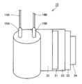
- FIG. 1 is a schematic cross-sectional view of the electrolytic capacitor according to the present embodiment
- FIG. 2 is a schematic view of a developed capacitor element according to the electrolytic capacitor.
- the electrolytic capacitor includes, for example, a capacitor element 10, a bottomed case 11 for housing the capacitor element 10, a sealing member 12 for closing the opening of the bottomed case 11, a seat plate 13 for covering the sealing member 12, and sealing It comprises lead wires 14A and 14B which are led out from the member 12 and penetrate the seat plate 13, lead tabs 15A and 15B for connecting the lead wires and the electrodes of the capacitor element 10, and an electrolytic solution (not shown).
- the vicinity of the open end of the bottomed case 11 is drawn inward, and the open end is curled so as to be crimped to the sealing member 12.
- the capacitor element 10 is manufactured from a wound body as shown in FIG.
- the wound body includes an anode body 21 connected to the lead tab 15A, a cathode body 22 connected to the lead tab 15B, and a separator 23.
- the wound body is a semi-finished product in which a solid electrolyte is not formed between the anode body 21 and the cathode body 22.
- FIG. 2 has shown the state in which one part was expand
- the anode body 21 is provided with a metal foil roughened so that the surface has irregularities, and a chemical conversion film is formed on the metal foil having irregularities.
- a solid electrolyte adheres to at least a part of the surface of the chemical conversion film.
- the solid electrolyte may cover at least a part of the surface of the cathode body 22 and / or the surface of the separator 23.
- the capacitor element 10 in which the solid electrolyte is formed is accommodated in the bottomed case 11 together with the electrolytic solution. «Method of manufacturing electrolytic capacitor» Hereinafter, an example of the manufacturing method of the electrolytic capacitor which concerns on this embodiment is demonstrated for every process.
- a metal foil which is a raw material of anode body 21 is prepared.
- the type of metal is not particularly limited, but it is preferable to use a valve metal such as aluminum, tantalum, niobium or an alloy containing a valve metal from the viewpoint of easy formation of a chemical conversion film.
- the surface of the metal foil is roughened.
- a plurality of irregularities are formed on the surface of the metal foil.
- the roughening is preferably performed by etching the metal foil.
- the etching process may be performed by, for example, a direct current electrolysis method or an alternating current electrolysis method.
- a chemical conversion film of thickness T is formed on the surface of the roughened metal foil.
- the forming method is not particularly limited, but the metal foil can be formed by chemical conversion treatment.
- a metal foil is immersed in a chemical conversion solution such as an ammonium adipate solution to perform heat treatment.
- the metal foil may be immersed in a chemical conversion solution and a voltage may be applied.
- a metal foil can be used for the cathode body 22 as in the case of the anode body 21.
- the type of metal is not particularly limited, but it is preferable to use a valve metal such as aluminum, tantalum, niobium or an alloy containing a valve metal. If necessary, the surface of the cathode body 22 may be roughened.
- a layer containing titanium or carbon may be formed on the surface of the cathode body 22.
- (Iii) Preparation of wound body Next, using the anode body 21, the cathode body 22 and the separator 23, a wound body is produced as shown in FIG. The end of the cathode body 22 located at the outermost layer is fixed with a winding tape 24.
- the wound body may be further subjected to a chemical conversion treatment.
- a non-woven fabric mainly composed of cellulose, polyethylene terephthalate, vinylon, aramid fiber or the like can be used.
- a solid electrolyte is attached to the surface of the chemical conversion film included in the wound body, and capacitor element 10 is manufactured.
- the conductive polymer synthesized in situ by chemical polymerization or electrolytic polymerization may be attached to the chemical conversion film using a polymerization solution.
- the polymerization liquid is a solution containing a monomer or an oligomer, a dopant and the like.
- an oxidizing agent is added to the polymerization solution.
- a conductive polymer synthesized in advance may be attached to the chemical conversion film.
- monomers and oligomers pyrrole, aniline, thiophene, derivatives thereof and the like are used.
- the conductive polymer synthesized in advance it is preferable to use a polymer dispersion.
- the polymer dispersion contains a liquid component, a conductive polymer dispersed in the liquid component, and a dopant.
- a method for applying the polymer dispersion to the surface of the chemical conversion film for example, a method in which the polymer dispersion is impregnated with the wound body and dried is preferable because it is simple.
- the polymer dispersion preferably contains PEDOT as a conductive polymer, and preferably contains PSS as a dopant.
- the step of applying the polymer dispersion to the surface of the chemical conversion film and the step of drying the wound body may be repeated twice or more. By performing these steps multiple times, the coverage of the solid electrolyte with respect to the chemical conversion film can be increased.
- Step of impregnating the capacitor element 10 with the electrolytic solution the capacitor element 10 is impregnated with the electrolytic solution.
- the method for impregnating the capacitor element 10 with the electrolytic solution is not particularly limited.
- metals such as aluminum, stainless steel, copper, iron, a brass, or these alloys can be used.
- a lateral drawing process is performed in the vicinity of the open end of the bottomed case 11, and the open end is crimped to the sealing member 12 and curled. Then, by arranging the seat plate 13 in the curled portion, the electrolytic capacitor as shown in FIG. 1 is completed. Thereafter, the aging process may be performed while applying the rated voltage.
- the winding type electrolytic capacitor has been described, but the scope of application of the present invention is not limited to the above, and other electrolytic capacitors, for example, chip type electrolysis using a sintered metal of metal as an anode body
- the present invention is also applicable to a multilayer electrolytic capacitor using a capacitor or a metal plate as an anode body.
- Second Embodiment An electrolytic capacitor according to a second embodiment of the present invention will be described.
- the electrolytic capacitor according to the second embodiment has the same configuration as that of the first embodiment except that it includes at least one of a composite compound of an organic acid and an inorganic acid and a derivative thereof as the first acid component. Therefore, the description of the overlapping contents is omitted.
- the complex compound as the first acid component contains one or more selected from the group consisting of borodisalicylic acid, borodiglycolic acid, and borodioxalic acid.
- the concentration of the solute contained in the electrolytic solution that is, the total concentration of the acid component including the first acid component and the base component is 10% by mass or more and less than 40% by mass.
- the concentration of the solute is more preferably 15% by mass or more and 35% by mass or less, and particularly preferably 20% by mass or more and 35% by mass or less.
- the first acid component is an anode body as in the first embodiment even if the concentration of the solute is 10% by mass or more because the degree of dissociation in the electrolytic solution is high. It is easy to reach the vicinity of the defects of the above, and the self-repairing performance of the conversion film can be improved.
- Example 1 A wound type electrolytic capacitor ( ⁇ 10 mm ⁇ L (length) 10 mm) with a rated voltage Vw of 25 volts and a rated capacitance of 33 ⁇ F was produced in the following manner. (Preparation of anode body) The aluminum foil of 100 ⁇ m in thickness was etched to roughen the surface of the aluminum foil.
- the surface of the roughened aluminum foil was subjected to a chemical conversion treatment to form a chemical conversion film.
- the conversion treatment was performed by immersing the aluminum foil in an ammonium adipate solution and applying a voltage of 40 volts to the aluminum foil. Thereafter, the aluminum foil was cut into 6 mm ⁇ 120 mm to prepare an anode body. V / Vw was set to 1.6. The thickness T of the chemical conversion film was 55 nm. (Preparation of cathode body) An etching process was performed on a 50 ⁇ m thick aluminum foil to roughen the surface of the aluminum foil. Thereafter, the aluminum foil was cut into 6 mm ⁇ 120 mm to prepare a cathode body.
- the anode lead tab and the cathode lead tab were connected to the anode body and the cathode body, and the anode body and the cathode body were wound via the separator while winding the lead tab.
- An anode lead wire and a cathode lead wire were respectively connected to the end of each lead tab protruding from the winding body.
- the obtained wound body was subjected to formation again, and a conversion coating was formed on the cut end of the anode body.
- the end of the outer surface of the wound body was fixed with a winding tape.
- a mixed solution was prepared by dissolving 3,4-ethylenedioxythiophene and polystyrene sulfonic acid (PSS, weight average molecular weight 100,000) in ion exchange water. While stirring the mixed solution, iron (III) sulfate (oxidizing agent) was added to carry out a polymerization reaction. Thereafter, the reaction solution is dialyzed, Unreacted monomers and oxidizing agents were removed to obtain a polymer dispersion comprising polyethylenedioxythiophene (PEDOT / PSS) doped with about 5% by weight of PSS.
- PSS polystyrene sulfonic acid
- o-phthalic acid as a first acid component and triethylamine as a first base component were dissolved at a concentration of 19% by mass in total and an equivalent ratio (initial equivalent ratio) of 1.
- PEG weight average molecular weight 300
- o-phthalic acid was added, and 3% by mass of pyrogallol was added to adjust the pH of the electrolyte to 3.5 to prepare an electrolyte.
- the capacitor element was immersed in the electrolytic solution for 5 minutes in a reduced pressure atmosphere (40 kPa).
- concentration of each component is a ratio at the time of making mass of the electrolyte solution obtained 100%.
- the concentration of the acid component was 28.2% by mass, and the concentration of the base component was 5.8% by mass.
- the capacitor element impregnated with the electrolytic solution was sealed to complete an electrolytic capacitor (A1) as shown in FIG. Thereafter, while applying the rated voltage Vw, aging was performed at 95 ° C. for 90 minutes.
- ⁇ Evaluation> The capacitance and ESR after aging and after 2500 hours were measured for the capacitor A1. The rate of change was calculated by dividing the value after 2500 hours by the value after aging. The results are shown in Table 1.
- Electrolytic capacitors A2 to A5 were produced in the same manner as in Example 1 except that the concentration of PEG was changed as shown in Table 1, and evaluated in the same manner. The results are shown in Table 1. Comparative Example 1 That the initial solute concentration was 10% by mass, the concentration of additional o-phthalic acid was 4% by mass, and the original equivalent ratio of the first acid component and the first base component was not changed; An electrolytic capacitor B1 was produced and evaluated in the same manner as in Example 1 except that no pyrogallol was added (the total concentration of the solutes was 14% by mass). The results are shown in Table 1. The concentration of the acid component was 10.9% by mass, and the concentration of the base component was 3.1% by mass. Comparative Example 2 An electrolytic capacitor B2 was produced and evaluated in the same manner as in Comparative Example 1 except that the formation voltage V was 45 volts and V / Vw was 1.8. The results are shown in Table 1.
- Example 6 Similar to Example 1 except that 4% by mass of pyromellitic acid and 5% by mass of pyrogallol were added instead of the additional o-phthalic acid (12% by mass) and the concentration of PEG was 15% by mass. Then, an electrolytic capacitor A6 was produced and evaluated in the same manner. The results are shown in Table 2.
- Example 7 Except that the initial solute concentration is 12% by mass without changing the initial equivalent ratio of the first acid component and the first base component, and that 3% by mass of pyromellitic acid is added instead of pyrogallol. In the same manner as in Example 1, an electrolytic capacitor A7 was produced and evaluated in the same manner. The results are shown in Table 2.
- Example 8 In the same manner as in Example 1 except that the initial solute concentration was 10% by mass without changing the initial equivalent ratio of the first acid component and the first base component, and that pyrogallol was not added.
- the electrolytic capacitor A8 was produced and evaluated in the same manner. The results are shown in Table 2.
- Example 9 An electrolytic capacitor A9 was produced and evaluated in the same manner as in Example 1 except that the concentration of additional o-phthalic acid was changed to 6% by mass. The results are shown in Table 2.
- Example 10 That the initial solute concentration was 25% by mass, the concentration of the additional o-phthalic acid was 10% by mass, and the original equivalent ratio of the first acid component and the first base component was not changed;
- An electrolytic capacitor A10 was produced and evaluated in the same manner as in Example 1 except that the concentration of pyrogallol was changed to 5% by mass. The results are shown in Table 2.
- Example 11 An electrolytic capacitor A11 was produced and evaluated in the same manner as in Example 1 except that the formation voltage V was 35 volts and V / Vw was 1.4 and pyrogallol was not added. . The results are shown in Table 3. Comparative Example 3 An electrolytic capacitor B3 was produced and evaluated in the same manner as in Comparative Example 1 except that the formation voltage V was 35 volts and V / Vw was 1.4. The results are shown in Table 3.
- Example 12 In place of triethylamine as the first base component, an amidine 1,2,3,4-tetramethylimidazolinium was used, and the initial equivalent ratio between the first acid component and the first base component was changed. Instead, an electrolytic capacitor A12 was produced and evaluated in the same manner as in Example 1 except that the initial solute concentration was 14% by mass. The results are shown in Table 4. The concentration of the acid component was 22.2% by mass, and the concentration of the base component was 6.8% by mass. Example 13 An electrolytic capacitor A13 was produced and evaluated in the same manner as in Example 12 except that PEG was not added. The results are shown in Table 4.
- the present invention can be applied to a hybrid electrolytic capacitor comprising a solid electrolyte and an electrolytic solution.
Landscapes
- Engineering & Computer Science (AREA)
- Power Engineering (AREA)
- Chemical & Material Sciences (AREA)
- Chemical Kinetics & Catalysis (AREA)
- Electrochemistry (AREA)
- Microelectronics & Electronic Packaging (AREA)
- Electric Double-Layer Capacitors Or The Like (AREA)
- Compositions Of Macromolecular Compounds (AREA)
- Materials Engineering (AREA)
Priority Applications (7)
| Application Number | Priority Date | Filing Date | Title |
|---|---|---|---|
| JP2019545671A JP7336686B2 (ja) | 2017-09-29 | 2018-09-28 | 電解コンデンサ |
| CN201880061703.1A CN111149183B (zh) | 2017-09-29 | 2018-09-28 | 电解电容器 |
| US16/810,105 US11195664B2 (en) | 2017-09-29 | 2020-03-05 | Electrolytic capacitor |
| US17/518,849 US11715605B2 (en) | 2017-09-29 | 2021-11-04 | Electrolytic capacitor |
| JP2023071003A JP7759581B2 (ja) | 2017-09-29 | 2023-04-24 | 電解コンデンサ |
| US18/208,788 US12112899B2 (en) | 2017-09-29 | 2023-06-12 | Electrolytic capacitor |
| JP2024202757A JP2025015813A (ja) | 2017-09-29 | 2024-11-20 | 電解コンデンサ |
Applications Claiming Priority (2)
| Application Number | Priority Date | Filing Date | Title |
|---|---|---|---|
| JP2017-191961 | 2017-09-29 | ||
| JP2017191961 | 2017-09-29 |
Related Child Applications (1)
| Application Number | Title | Priority Date | Filing Date |
|---|---|---|---|
| US16/810,105 Continuation US11195664B2 (en) | 2017-09-29 | 2020-03-05 | Electrolytic capacitor |
Publications (1)
| Publication Number | Publication Date |
|---|---|
| WO2019065951A1 true WO2019065951A1 (ja) | 2019-04-04 |
Family
ID=65900901
Family Applications (1)
| Application Number | Title | Priority Date | Filing Date |
|---|---|---|---|
| PCT/JP2018/036209 Ceased WO2019065951A1 (ja) | 2017-09-29 | 2018-09-28 | 電解コンデンサ |
Country Status (4)
| Country | Link |
|---|---|
| US (3) | US11195664B2 (https=) |
| JP (3) | JP7336686B2 (https=) |
| CN (1) | CN111149183B (https=) |
| WO (1) | WO2019065951A1 (https=) |
Cited By (3)
| Publication number | Priority date | Publication date | Assignee | Title |
|---|---|---|---|---|
| JP2021027285A (ja) * | 2019-08-08 | 2021-02-22 | 株式会社東芝 | アルミニウム電解コンデンサ、電気機器、及びアルミニウム電解コンデンサの製造方法 |
| JPWO2023190203A1 (https=) * | 2022-03-31 | 2023-10-05 | ||
| WO2025070507A1 (ja) * | 2023-09-28 | 2025-04-03 | パナソニックIpマネジメント株式会社 | 電解コンデンサ |
Families Citing this family (6)
| Publication number | Priority date | Publication date | Assignee | Title |
|---|---|---|---|---|
| DE112016005410T5 (de) | 2015-11-27 | 2018-09-20 | Panasonic Intellectual Property Management Co., Ltd. | Elektrolytkondensator und Verfahren zur seiner Herstellung |
| CN111149183B (zh) | 2017-09-29 | 2022-04-26 | 松下知识产权经营株式会社 | 电解电容器 |
| US11450485B2 (en) * | 2018-07-18 | 2022-09-20 | Nippon Chemi-Con Corporation | Solid electrolytic capacitor |
| CN112424892B (zh) * | 2018-09-21 | 2022-11-01 | 日本贵弥功株式会社 | 固体电解电容器 |
| CN112582181B (zh) * | 2020-11-10 | 2022-02-11 | 西安交通大学 | 一种高抗水合性低压铝电解电容器用电解液和制备方法 |
| CN115061003B (zh) * | 2022-08-17 | 2022-11-25 | 南通江海电容器股份有限公司 | 电解电容器的寿命评估方法及装置 |
Citations (7)
| Publication number | Priority date | Publication date | Assignee | Title |
|---|---|---|---|---|
| JP2005286251A (ja) * | 2004-03-30 | 2005-10-13 | Nippon Chemicon Corp | 固体電解コンデンサ |
| JP2005327945A (ja) * | 2004-05-17 | 2005-11-24 | Japan Carlit Co Ltd:The | アルミニウム電解コンデンサ用電解液及び該電解液を用いたアルミニウム電解コンデンサ |
| JP2006108650A (ja) * | 2004-09-07 | 2006-04-20 | Matsushita Electric Ind Co Ltd | 電解コンデンサ用電解液及びそれを用いた電解コンデンサ |
| JP2007080888A (ja) * | 2005-09-12 | 2007-03-29 | Sanyo Chem Ind Ltd | 電解コンデンサ用電解液及びそれを用いた電解コンデンサ |
| JP2008010657A (ja) * | 2006-06-29 | 2008-01-17 | Sanyo Electric Co Ltd | 電解コンデンサの製造方法および電解コンデンサ |
| WO2011099261A1 (ja) * | 2010-02-15 | 2011-08-18 | パナソニック株式会社 | 電解コンデンサ |
| JP2017069537A (ja) * | 2015-09-30 | 2017-04-06 | カーリットホールディングス株式会社 | 電解コンデンサ |
Family Cites Families (14)
| Publication number | Priority date | Publication date | Assignee | Title |
|---|---|---|---|---|
| FR2432204A1 (fr) * | 1978-07-28 | 1980-02-22 | Lignes Telegraph Telephon | Procede de fabrication de condensateurs a electrolyte solide au tantale |
| JPS63245916A (ja) * | 1986-09-11 | 1988-10-13 | 旭硝子株式会社 | アルミ電解コンデンサ |
| JPH07249543A (ja) * | 1994-03-14 | 1995-09-26 | Matsushita Electric Ind Co Ltd | 電解コンデンサ |
| US7268997B2 (en) * | 2005-08-29 | 2007-09-11 | Takeshi Saitou | Solid electrolytic capacitor |
| JP4739148B2 (ja) * | 2005-08-29 | 2011-08-03 | Necトーキン株式会社 | 固体電解コンデンサ |
| JP2007103498A (ja) * | 2005-09-30 | 2007-04-19 | Mitsubishi Chemicals Corp | 電解コンデンサ用電解液及び電解コンデンサ |
| JP2007142353A (ja) * | 2005-10-17 | 2007-06-07 | Matsushita Electric Ind Co Ltd | アルミ電解コンデンサ |
| JP4911509B2 (ja) * | 2007-04-03 | 2012-04-04 | 三洋電機株式会社 | 電解コンデンサおよびその製造方法 |
| JP2009266926A (ja) * | 2008-04-23 | 2009-11-12 | Panasonic Corp | 固体電解コンデンサおよびその製造方法 |
| CN101404213B (zh) * | 2008-11-13 | 2011-05-18 | 北京七一八友益电子有限责任公司 | 固体片式钽电解电容器及其制造方法 |
| CN103295783B (zh) * | 2013-05-16 | 2015-09-09 | 中国振华(集团)新云电子元器件有限责任公司 | 一种电解电容器的制造方法 |
| DE112017001358T5 (de) * | 2016-03-16 | 2018-11-29 | Panasonic Intellectual Property Management Co., Ltd. | Elektrolytkondensator |
| KR102550879B1 (ko) * | 2016-12-13 | 2023-07-03 | 미쯔비시 케미컬 주식회사 | 폴리오르가노실록산, 폴리오르가노실록산 조성물, 및 그 경화물, 그리고 폴리오르가노실록산을 포함하는 전해 콘덴서용 전해액 및 그것을 사용한 전해 콘덴서 |
| CN111149183B (zh) * | 2017-09-29 | 2022-04-26 | 松下知识产权经营株式会社 | 电解电容器 |
-
2018
- 2018-09-28 CN CN201880061703.1A patent/CN111149183B/zh active Active
- 2018-09-28 JP JP2019545671A patent/JP7336686B2/ja active Active
- 2018-09-28 WO PCT/JP2018/036209 patent/WO2019065951A1/ja not_active Ceased
-
2020
- 2020-03-05 US US16/810,105 patent/US11195664B2/en active Active
-
2021
- 2021-11-04 US US17/518,849 patent/US11715605B2/en active Active
-
2023
- 2023-04-24 JP JP2023071003A patent/JP7759581B2/ja active Active
- 2023-06-12 US US18/208,788 patent/US12112899B2/en active Active
-
2024
- 2024-11-20 JP JP2024202757A patent/JP2025015813A/ja active Pending
Patent Citations (7)
| Publication number | Priority date | Publication date | Assignee | Title |
|---|---|---|---|---|
| JP2005286251A (ja) * | 2004-03-30 | 2005-10-13 | Nippon Chemicon Corp | 固体電解コンデンサ |
| JP2005327945A (ja) * | 2004-05-17 | 2005-11-24 | Japan Carlit Co Ltd:The | アルミニウム電解コンデンサ用電解液及び該電解液を用いたアルミニウム電解コンデンサ |
| JP2006108650A (ja) * | 2004-09-07 | 2006-04-20 | Matsushita Electric Ind Co Ltd | 電解コンデンサ用電解液及びそれを用いた電解コンデンサ |
| JP2007080888A (ja) * | 2005-09-12 | 2007-03-29 | Sanyo Chem Ind Ltd | 電解コンデンサ用電解液及びそれを用いた電解コンデンサ |
| JP2008010657A (ja) * | 2006-06-29 | 2008-01-17 | Sanyo Electric Co Ltd | 電解コンデンサの製造方法および電解コンデンサ |
| WO2011099261A1 (ja) * | 2010-02-15 | 2011-08-18 | パナソニック株式会社 | 電解コンデンサ |
| JP2017069537A (ja) * | 2015-09-30 | 2017-04-06 | カーリットホールディングス株式会社 | 電解コンデンサ |
Cited By (5)
| Publication number | Priority date | Publication date | Assignee | Title |
|---|---|---|---|---|
| JP2021027285A (ja) * | 2019-08-08 | 2021-02-22 | 株式会社東芝 | アルミニウム電解コンデンサ、電気機器、及びアルミニウム電解コンデンサの製造方法 |
| JP7444561B2 (ja) | 2019-08-08 | 2024-03-06 | 株式会社東芝 | アルミニウム電解コンデンサ、電気機器、及びアルミニウム電解コンデンサの製造方法 |
| JPWO2023190203A1 (https=) * | 2022-03-31 | 2023-10-05 | ||
| WO2023190203A1 (ja) * | 2022-03-31 | 2023-10-05 | パナソニックIpマネジメント株式会社 | 電解コンデンサ |
| WO2025070507A1 (ja) * | 2023-09-28 | 2025-04-03 | パナソニックIpマネジメント株式会社 | 電解コンデンサ |
Also Published As
| Publication number | Publication date |
|---|---|
| US11715605B2 (en) | 2023-08-01 |
| CN111149183A (zh) | 2020-05-12 |
| US20220059292A1 (en) | 2022-02-24 |
| JP7336686B2 (ja) | 2023-09-01 |
| US20200203081A1 (en) | 2020-06-25 |
| US20230326684A1 (en) | 2023-10-12 |
| US11195664B2 (en) | 2021-12-07 |
| JP2025015813A (ja) | 2025-01-30 |
| US12112899B2 (en) | 2024-10-08 |
| JP2023089289A (ja) | 2023-06-27 |
| CN111149183B (zh) | 2022-04-26 |
| JP7759581B2 (ja) | 2025-10-24 |
| JPWO2019065951A1 (ja) | 2020-11-05 |
Similar Documents
| Publication | Publication Date | Title |
|---|---|---|
| JP7759581B2 (ja) | 電解コンデンサ | |
| US10563318B2 (en) | Electrolytic capacitor | |
| JP6928788B2 (ja) | 電解コンデンサおよびその製造方法 | |
| JP6550595B2 (ja) | 電解コンデンサおよびその製造方法 | |
| JP6941765B2 (ja) | 電解コンデンサ | |
| JP2011109023A (ja) | 固体電解コンデンサおよびその製造方法 | |
| WO2021149739A1 (ja) | 固体電解コンデンサ | |
| JP7731057B2 (ja) | 電解コンデンサおよびその製造方法 | |
| WO2017163727A1 (ja) | 電解コンデンサ | |
| WO2017017947A1 (ja) | 電解コンデンサ | |
| JP7607227B2 (ja) | 電解コンデンサ | |
| WO2016103617A1 (ja) | 電解コンデンサの製造方法 | |
| US20260011508A1 (en) | Electrolytic capacitor and production method therefor | |
| JP6604497B2 (ja) | 電解コンデンサの製造方法 | |
| WO2019131478A1 (ja) | 電解コンデンサ |
Legal Events
| Date | Code | Title | Description |
|---|---|---|---|
| 121 | Ep: the epo has been informed by wipo that ep was designated in this application |
Ref document number: 18863704 Country of ref document: EP Kind code of ref document: A1 |
|
| ENP | Entry into the national phase |
Ref document number: 2019545671 Country of ref document: JP Kind code of ref document: A |
|
| NENP | Non-entry into the national phase |
Ref country code: DE |
|
| 122 | Ep: pct application non-entry in european phase |
Ref document number: 18863704 Country of ref document: EP Kind code of ref document: A1 |