WO2019065951A1 - 電解コンデンサ - Google Patents
電解コンデンサ Download PDFInfo
- Publication number
- WO2019065951A1 WO2019065951A1 PCT/JP2018/036209 JP2018036209W WO2019065951A1 WO 2019065951 A1 WO2019065951 A1 WO 2019065951A1 JP 2018036209 W JP2018036209 W JP 2018036209W WO 2019065951 A1 WO2019065951 A1 WO 2019065951A1
- Authority
- WO
- WIPO (PCT)
- Prior art keywords
- acid
- mass
- electrolytic capacitor
- chemical conversion
- component
- Prior art date
Links
Images

Classifications
-
- H—ELECTRICITY
- H01—ELECTRIC ELEMENTS
- H01G—CAPACITORS; CAPACITORS, RECTIFIERS, DETECTORS, SWITCHING DEVICES OR LIGHT-SENSITIVE DEVICES, OF THE ELECTROLYTIC TYPE
- H01G9/00—Electrolytic capacitors, rectifiers, detectors, switching devices, light-sensitive or temperature-sensitive devices; Processes of their manufacture
- H01G9/004—Details
- H01G9/022—Electrolytes; Absorbents
- H01G9/025—Solid electrolytes
- H01G9/028—Organic semiconducting electrolytes, e.g. TCNQ
-
- H—ELECTRICITY
- H01—ELECTRIC ELEMENTS
- H01G—CAPACITORS; CAPACITORS, RECTIFIERS, DETECTORS, SWITCHING DEVICES OR LIGHT-SENSITIVE DEVICES, OF THE ELECTROLYTIC TYPE
- H01G9/00—Electrolytic capacitors, rectifiers, detectors, switching devices, light-sensitive or temperature-sensitive devices; Processes of their manufacture
- H01G9/004—Details
- H01G9/022—Electrolytes; Absorbents
- H01G9/035—Liquid electrolytes, e.g. impregnating materials
-
- H—ELECTRICITY
- H01—ELECTRIC ELEMENTS
- H01G—CAPACITORS; CAPACITORS, RECTIFIERS, DETECTORS, SWITCHING DEVICES OR LIGHT-SENSITIVE DEVICES, OF THE ELECTROLYTIC TYPE
- H01G9/00—Electrolytic capacitors, rectifiers, detectors, switching devices, light-sensitive or temperature-sensitive devices; Processes of their manufacture
- H01G9/145—Liquid electrolytic capacitors
-
- H—ELECTRICITY
- H01—ELECTRIC ELEMENTS
- H01G—CAPACITORS; CAPACITORS, RECTIFIERS, DETECTORS, SWITCHING DEVICES OR LIGHT-SENSITIVE DEVICES, OF THE ELECTROLYTIC TYPE
- H01G9/00—Electrolytic capacitors, rectifiers, detectors, switching devices, light-sensitive or temperature-sensitive devices; Processes of their manufacture
- H01G9/15—Solid electrolytic capacitors
- H01G9/151—Solid electrolytic capacitors with wound foil electrodes
-
- H—ELECTRICITY
- H01—ELECTRIC ELEMENTS
- H01G—CAPACITORS; CAPACITORS, RECTIFIERS, DETECTORS, SWITCHING DEVICES OR LIGHT-SENSITIVE DEVICES, OF THE ELECTROLYTIC TYPE
- H01G9/00—Electrolytic capacitors, rectifiers, detectors, switching devices, light-sensitive or temperature-sensitive devices; Processes of their manufacture
- H01G9/004—Details
- H01G9/022—Electrolytes; Absorbents
-
- H—ELECTRICITY
- H01—ELECTRIC ELEMENTS
- H01G—CAPACITORS; CAPACITORS, RECTIFIERS, DETECTORS, SWITCHING DEVICES OR LIGHT-SENSITIVE DEVICES, OF THE ELECTROLYTIC TYPE
- H01G9/00—Electrolytic capacitors, rectifiers, detectors, switching devices, light-sensitive or temperature-sensitive devices; Processes of their manufacture
- H01G9/004—Details
- H01G9/04—Electrodes or formation of dielectric layers thereon
- H01G9/042—Electrodes or formation of dielectric layers thereon characterised by the material
Definitions
- the present invention relates to an electrolytic capacitor comprising a solid electrolyte and an electrolytic solution.
- Patent Document 1 discloses a hybrid electrolytic capacitor in which an oxide film (chemical conversion film) is formed on the surface of an anode body.
- the first aspect of the present invention is an electrolytic capacitor comprising a capacitor element and an electrolytic solution, wherein the capacitor element is an anode body having a chemical conversion film, and a solid electrolyte in contact with the chemical conversion film.
- the electrolyte contains a solvent and a solute, and the solvent contains at least one selected from the group consisting of lactone compounds, glycol compounds and sulfone compounds, and the solute contains a first acid component.
- the ratio of the formation voltage V volts applied to the anode body to form the conversion coating and the rated voltage Vw of the electrolytic capacitor V / Vw is 1.7 or less, on the electrolytic capacitor.
- a second aspect of the present invention is an electrolytic capacitor comprising a capacitor element and an electrolytic solution, wherein the capacitor element comprises an anode body having a chemical conversion film, and a solid electrolyte in contact with the chemical conversion film.
- the electrolyte includes a solvent and a solute, and the solvent includes at least one selected from the group consisting of a lactone compound, a glycol compound and a sulfone compound, and the solute is an organic acid as a first acid component.
- the electrolytic capacitor according to the present embodiment includes a capacitor element and an electrolytic solution.
- the capacitor element includes an anode body having a chemical conversion film and a solid electrolyte in contact with the chemical conversion film.
- the solid electrolyte and the chemical conversion film are in contact with each other. Therefore, in order to reduce the leak current, conventionally, the formation voltage V is set to a high value about twice the rated voltage Vw of the electrolytic capacitor to form a chemical conversion film having a sufficient thickness. Therefore, it is difficult to increase the capacitance of the electrolytic capacitor or to miniaturize the electrolytic capacitor by reducing the ratio (V / Vw) between the rated voltage Vw and the formation voltage V in the hybrid electrolytic capacitor. Met.
- a solute containing at least one of benzenedicarboxylic acid and its derivative as a first acid component and at least one of an amine and an amidine as a base component is used.
- concentration of the sum total of the acid component containing a 1st acid component, and a base component is 15 mass% or more and less than 40 mass%.
- a specific solvent is used. Specifically, at least one selected from the group consisting of ⁇ -butyrolactone, ethylene glycol and sulfolane is used as the solvent.
- the electrolytic solution into the composition as described above By making the electrolytic solution into the composition as described above, the first acid component contained in the solute can easily reach the vicinity of the defect of the anode body. Therefore, the self-repairing performance of the chemical conversion film is improved, and the capacitance and ESR can be maintained. Accordingly, the ratio V / Vw of the formation voltage V volts to the rated voltage Vw volts can be made 1.7 or less.
- the concentration of the polymer component is 1% by mass or more and 15% by mass or less.
- the chemical conversion film is not limited to a film formed by a method (hereinafter, the first method) of applying a predetermined formation voltage to the anode body in a state of being immersed in an acidic aqueous solution (hereinafter, a chemical conversion solution).
- the chemical conversion film may be formed by heat treatment of the anode body in a state of being immersed in the chemical conversion solution (hereinafter, the second method).
- the chemical conversion film is formed by the first method, a chemical conversion film having a thickness T in accordance with the formation voltage is formed. That is, the formation voltage is obtained from the thickness T of the chemical conversion film.
- the formation voltage necessary for forming the chemical conversion film by the first method can be determined from the thickness T thereof. That is, the chemical conversion voltage V includes the voltage applied to the anode body to form a chemical conversion film of thickness T, and the voltage necessary to form a chemical conversion film of thickness T.
- the rated voltage Vw is the upper limit voltage defined as the rating, and is the maximum value of the voltage applied between the electrodes of the electrolytic capacitor.
- the electrolyte solution contains a solvent and a solute.
- the pH of the electrolyte is preferably 4.5 or less. By setting the pH of the electrolytic solution to 4.5 or less, the dedoping phenomenon of the solid electrolyte is easily suppressed. Therefore, ESR can be maintained.
- the pH of the electrolytic solution is more preferably 4 or less, and particularly preferably 3.8 or less.
- the pH of the electrolyte is preferably 2 or more.
- the conductivity of the electrolytic solution is preferably 0.01 mS / cm or more and 3 mS / cm or less. In this case, when the ratio of the formation voltage V volts to the rated voltage Vw volts: V / Vw is 1.7 or less, the self-repairing performance can be further improved.
- the solvent preferably contains at least one selected from the group consisting of ⁇ -butyrolactone ( ⁇ BL), ethylene glycol (EG) and sulfolane (SL) (hereinafter referred to as the main solvent).
- ⁇ BL ⁇ -butyrolactone
- EG ethylene glycol
- SL sulfolane
- glycol compounds other than EG glycol compounds other than SL
- lactone compounds other than ⁇ BL may be used.
- glycol compounds other than EG diethylene glycol, triethylene glycol, propylene glycol and the like can be used.
- sulfone compounds other than SL dimethylsulfoxide, diethylsulfoxide and the like can be used.
- lactone compound other than ⁇ BL ⁇ -valerolactone can be used. 50 mass% or more is preferable, as for the ratio of the main solvent (for example, total of (gamma) BL, EG, and SL) contained in a solvent, 60 mass% or more is more preferable, and 70 mass% or more is more preferable.
- the solvent can contain a carbonate compound, a monohydric or trihydric or higher alcohol, and the like as a solvent other than the main solvent (hereinafter, a co-solvent).
- a carbonate compound dimethyl carbonate (DMC), diethyl carbonate (DEC), ethyl methyl carbonate (EMC), ethylene carbonate (EC), propylene carbonate (PC), fluoro ethylene carbonate (FEC), etc.
- DMC dimethyl carbonate
- DEC diethyl carbonate
- EMC ethyl methyl carbonate
- EMC ethylene carbonate
- PC propylene carbonate
- FEC fluoro ethylene carbonate
- glycerin or polyglycerin can be used as the alcohol. These may be used alone or in combination of two or more.
- the concentration of the solute is 15% by mass or more and 40% by mass or less.
- the concentration of the solute is more preferably 20% by mass or more and 40% by mass or less, and particularly preferably 20%
- the concentration of the solute is the sum of the concentration of the acid component and the concentration of the base component.
- the acid component includes a first acid component and a second acid component other than the first acid component.
- the base component includes an amine and / or an amidine (hereinafter, first base component), and a second base component other than the first base component.
- the solute contains at least one of benzenedicarboxylic acid and its derivative as a first acid component.
- the benzenedicarboxylic acid may be o-phthalic acid, m-phthalic acid or p-phthalic acid.
- Examples of derivatives of benzenedicarboxylic acid include 3-sulfophthalic acid having a sulfo group, 3,5-disulfophthalic acid, 4-sulfoisophthalic acid, 2-sulfoterephthalic acid, 2-methyl-5-sulfoterephthalic acid and the like. Be Among these, o-phthalic acid is preferred.
- the concentration of the first acid component contained in the electrolytic solution is preferably 5% by mass or more, and more preferably 15% by mass or more, from the viewpoint of easy dissociation. Moreover, 35 mass% or less is preferable, and, as for the density
- the acid component may contain a second acid component other than the first acid component.
- organic acid used as the second acid component examples include polycarboxylic acids, monocarboxylic acids and polyhydric phenols.
- polycarboxylic acids examples include aliphatic polycarboxylic acids: ([saturated polycarboxylic acids such as oxalic acid, malonic acid, succinic acid, glutaric acid, adipic acid, pimelic acid, suberic acid, azelaic acid, sebacic acid, 1, 6 -Decanedicarboxylic acid, 5,6-decanedicarboxylic acid], [unsaturated polycarboxylic acid such as maleic acid, fumaric acid, icotanic acid], aromatic polycarboxylic acid: (eg trimellitic acid, pyromellitic acid), Alicyclic polycarboxylic acids: (eg, cyclohexane-1,2-dicarboxylic acid, cyclohexene-1,2-dicarboxylic acid, etc.).
- saturated polycarboxylic acids such as oxalic acid, malonic acid, succinic acid, glutaric acid, adipic acid, pimelic acid
- monocarboxylic acids include aliphatic monocarboxylic acids (having 1 to 30 carbon atoms): ([saturated monocarboxylic acids such as formic acid, acetic acid, propionic acid, butyric acid, isobutyric acid, valeric acid, caproic acid, enanthate, caprylic acid , Pelargonic acid, lauric acid, myristic acid, stearic acid, behenic acid], [unsaturated monocarboxylic acid such as acrylic acid, methacrylic acid, oleic acid], aromatic monocarboxylic acid: (such as benzoic acid, cinnamic acid , Naphthoic acid, oxycarboxylic acid: (for example, salicylic acid, mandelic acid, resorcinic acid), among them, preferable among these are maleic acid, benzoic acid, pyromellitic acid, resorcynic acid, which has high conductivity and is thermally stable. It
- polyhydric phenols examples include catechol, resorcinol, hydroquinone, pyrogallol, phloroglucin and the like.
- an inorganic acid used as a 2nd acid component a carbon compound, a hydrogen compound, a boron compound, a sulfur compound, a nitrogen compound, and a phosphorus compound are mentioned.
- representative inorganic acids include phosphoric acid, phosphorous acid, hypophosphorous acid, alkyl phosphoric acid ester, boric acid, borofluoric acid, tetrafluorinated boric acid, hexafluorophosphoric acid, benzenesulfonic acid, naphthalenesulfonic acid Etc.
- a composite compound of an organic acid and an inorganic acid may be used as the second acid component.
- the complex compound for example, borodiglycolic acid, borodisuccinic acid, borodisalicylic acid and the like can be mentioned.
- At least one selected from the group consisting of aromatic polycarboxylic acids, polyhydric phenols, and oxycarboxylic acids is preferable as the second acid component in that self-repairing performance is further improved.
- 3 mass% or more is preferable, and, as for the density
- the solute contains at least one of an amine and an amidine as a first base component.
- the amine may be a primary amine, a secondary amine and a tertiary amine.
- Each amine may be an aliphatic amine, an aromatic amine or a heterocyclic amine.
- tertiary amines are preferred in that the effect of stabilizing ESR in the long term can be enhanced.
- tertiary amines include trialkylamines (trimethylamine, dimethylethylamine, methyldiethylamine, triethylamine, dimethyl n-propylamine, dimethylisopropylamine, methylethyl n-propylamine, methylethylisopropylamine, diethyl n-propylamine, diethyl
- examples thereof include isopropylamine, tri n-propylamine, triisopropylamine, tri n-butylamine, tri-t-butylamine and the like, and phenyl group-containing amines (dimethylphenylamine, methylethylphenylamine, diethylphenylamine and the like).
- trialkylamines such as trimethylamine, dimethylethylamine, methyl diethylamine and triethylamine are preferable in view of high conductivity.
- amidine compounds having an alkyl-substituted amidine group are preferable in terms of high conductivity.
- a compound which has an alkyl substituted amidine group an imidazole compound, a benzoimidazole compound, an alicyclic amidine compound (a pyrimidine compound, an imidazoline compound) is mentioned, for example.
- 3.5 mass% or more is preferable, and, as for the density
- concentration when the amine is contained in electrolyte solution, 3.5 mass% or more is preferable, and 5 mass% or more is more preferable. Moreover, 20 mass% or less is preferable, and, as for the density
- the concentration is preferably 3.5% by mass or more, and more preferably 5% by mass or more. Moreover, 20 mass% or less is preferable, and, as for the density
- the base component may contain a second base component other than the first base component.
- Examples of the second base component include ammonia and quaternary ammonium compounds. 0.1 mass% or more is preferable, and, as for the density
- the acid component is preferably in excess in equivalent ratio to the base component.
- the equivalent ratio of the acid component to the base component is desirably 1 to 30.
- the electrolytic solution may contain a polymer component. The polymer component is included to suppress the transpiration of the electrolytic solution and to improve the withstand voltage.
- the polymer component is not particularly limited.
- examples of the polymer component include polyalkylene glycol, derivatives of polyalkylene glycol, and compounds in which at least one of hydroxyl groups of polyhydric alcohol is substituted with polyalkylene glycol (including derivative).
- polyethylene glycol, polyethylene glycol glyceryl ether, polyethylene glycol diglyceryl ether, polyethylene glycol sorbitol ether, polypropylene glycol, polypropylene glycol glyceryl ether, polypropylene glycol diglyceryl ether, polypropylene glycol sorbitol ether, polybutylene glycol and the like can be mentioned. . These may be used alone or in combination of two or more.
- the above polyalkylene glycol may be a copolymer (a random copolymer, a block copolymer, a random block copolymer or the like).
- a copolymer of ethylene glycol and propylene glycol a copolymer of ethylene glycol and butylene glycol, a copolymer of propylene glycol and butylene glycol, and the like can be mentioned.
- the weight average molecular weight of the polymer component is preferably 200 or more. From the viewpoint of solubility in a solvent, the weight average molecular weight of the polymer component is preferably 20,000 or less, more preferably 5,000 or less.
- the concentration of the polymer component in the electrolytic solution is preferably 1% by mass or more and 15% by mass or less. When the concentration of the polymer component is in this range, evaporation of the electrolytic solution is suppressed, and migration of the first acid component is not hindered. Therefore, the self-repairing performance of the chemical conversion film is improved.
- the concentration of the polymer component in the electrolytic solution is more preferably 1% by mass or more and 10% by mass or less.
- the solid electrolyte contains, for example, a manganese compound or a conductive polymer.
- the conductive polymer for example, polypyrrole, polythiophene, polyaniline and derivatives thereof can be used.
- the solid electrolyte contains a dopant. More specifically, the solid electrolyte can include poly (3,4-ethylenedioxythiophene) (PEDOT) as a conductive polymer and polystyrenesulfonic acid (PSS) as a dopant.
- the solid electrolyte may be formed by applying a solution containing a monomer and a dopant to the chemical conversion film, and performing chemical polymerization or electrolytic polymerization in situ.
- a solid electrolyte by a method of applying a conductive polymer to a chemical conversion film in that excellent withstand voltage characteristics can be expected. That is, the solid electrolyte is formed by impregnating a polymer dispersion containing a liquid component, a conductive polymer dispersed in the liquid component, and a dopant into a chemical conversion film, and then volatilizing the liquid component. Is preferred.
- the concentration of the conductive polymer contained in the polymer dispersion is preferably 0.5 to 10% by mass.
- the average particle size D50 of the conductive polymer is preferably, for example, 0.01 to 0.5 ⁇ m.
- the average particle diameter D50 is a median diameter in the volume particle size distribution determined by the particle size distribution measuring apparatus by the dynamic light scattering method.
- the ratio V / Vw between the formation voltage V applied to the anode body to form a chemical conversion film of thickness T and the rated voltage Vw of the electrolytic capacitor is 1.7 or less.
- V / Vw may be 1.6 or less. From the viewpoint of suppressing the increase of the leak current, V / Vw is preferably equal to or greater than 1.4, and more preferably equal to or greater than 1.5.
- the formation voltage V is not particularly limited, and may be appropriately set such that V / Vw is 1.7 or less according to the rated voltage Vw.
- the thickness T of the chemical conversion film increases in proportion to the formation voltage V. For example, when the formation voltage V is 17 volts, the thickness T of the chemical conversion film is 24 nm. When the formation voltage V is 170 volts, the thickness T of the chemical conversion film is 238 nm. In other words, when the thickness T of the chemical conversion film is 238 nm, the formation voltage V applied to the anode body or necessary is 170 volts.
- the rated voltage Vw is also not particularly limited, but in the case of 100 V or less (that is, the thickness T of the chemical conversion film is 238 nm or less), the effects of the present invention are particularly easily exhibited. In particular, in the case of the rated voltage Vw of 70 volts or less at which the chemical conversion film becomes thinner, the effect of the present invention is further exhibited.
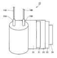
- FIG. 1 is a schematic cross-sectional view of the electrolytic capacitor according to the present embodiment
- FIG. 2 is a schematic view of a developed capacitor element according to the electrolytic capacitor.
- the electrolytic capacitor includes, for example, a capacitor element 10, a bottomed case 11 for housing the capacitor element 10, a sealing member 12 for closing the opening of the bottomed case 11, a seat plate 13 for covering the sealing member 12, and sealing It comprises lead wires 14A and 14B which are led out from the member 12 and penetrate the seat plate 13, lead tabs 15A and 15B for connecting the lead wires and the electrodes of the capacitor element 10, and an electrolytic solution (not shown).
- the vicinity of the open end of the bottomed case 11 is drawn inward, and the open end is curled so as to be crimped to the sealing member 12.
- the capacitor element 10 is manufactured from a wound body as shown in FIG.
- the wound body includes an anode body 21 connected to the lead tab 15A, a cathode body 22 connected to the lead tab 15B, and a separator 23.
- the wound body is a semi-finished product in which a solid electrolyte is not formed between the anode body 21 and the cathode body 22.
- FIG. 2 has shown the state in which one part was expand
- the anode body 21 is provided with a metal foil roughened so that the surface has irregularities, and a chemical conversion film is formed on the metal foil having irregularities.
- a solid electrolyte adheres to at least a part of the surface of the chemical conversion film.
- the solid electrolyte may cover at least a part of the surface of the cathode body 22 and / or the surface of the separator 23.
- the capacitor element 10 in which the solid electrolyte is formed is accommodated in the bottomed case 11 together with the electrolytic solution. «Method of manufacturing electrolytic capacitor» Hereinafter, an example of the manufacturing method of the electrolytic capacitor which concerns on this embodiment is demonstrated for every process.
- a metal foil which is a raw material of anode body 21 is prepared.
- the type of metal is not particularly limited, but it is preferable to use a valve metal such as aluminum, tantalum, niobium or an alloy containing a valve metal from the viewpoint of easy formation of a chemical conversion film.
- the surface of the metal foil is roughened.
- a plurality of irregularities are formed on the surface of the metal foil.
- the roughening is preferably performed by etching the metal foil.
- the etching process may be performed by, for example, a direct current electrolysis method or an alternating current electrolysis method.
- a chemical conversion film of thickness T is formed on the surface of the roughened metal foil.
- the forming method is not particularly limited, but the metal foil can be formed by chemical conversion treatment.
- a metal foil is immersed in a chemical conversion solution such as an ammonium adipate solution to perform heat treatment.
- the metal foil may be immersed in a chemical conversion solution and a voltage may be applied.
- a metal foil can be used for the cathode body 22 as in the case of the anode body 21.
- the type of metal is not particularly limited, but it is preferable to use a valve metal such as aluminum, tantalum, niobium or an alloy containing a valve metal. If necessary, the surface of the cathode body 22 may be roughened.
- a layer containing titanium or carbon may be formed on the surface of the cathode body 22.
- (Iii) Preparation of wound body Next, using the anode body 21, the cathode body 22 and the separator 23, a wound body is produced as shown in FIG. The end of the cathode body 22 located at the outermost layer is fixed with a winding tape 24.
- the wound body may be further subjected to a chemical conversion treatment.
- a non-woven fabric mainly composed of cellulose, polyethylene terephthalate, vinylon, aramid fiber or the like can be used.
- a solid electrolyte is attached to the surface of the chemical conversion film included in the wound body, and capacitor element 10 is manufactured.
- the conductive polymer synthesized in situ by chemical polymerization or electrolytic polymerization may be attached to the chemical conversion film using a polymerization solution.
- the polymerization liquid is a solution containing a monomer or an oligomer, a dopant and the like.
- an oxidizing agent is added to the polymerization solution.
- a conductive polymer synthesized in advance may be attached to the chemical conversion film.
- monomers and oligomers pyrrole, aniline, thiophene, derivatives thereof and the like are used.
- the conductive polymer synthesized in advance it is preferable to use a polymer dispersion.
- the polymer dispersion contains a liquid component, a conductive polymer dispersed in the liquid component, and a dopant.
- a method for applying the polymer dispersion to the surface of the chemical conversion film for example, a method in which the polymer dispersion is impregnated with the wound body and dried is preferable because it is simple.
- the polymer dispersion preferably contains PEDOT as a conductive polymer, and preferably contains PSS as a dopant.
- the step of applying the polymer dispersion to the surface of the chemical conversion film and the step of drying the wound body may be repeated twice or more. By performing these steps multiple times, the coverage of the solid electrolyte with respect to the chemical conversion film can be increased.
- Step of impregnating the capacitor element 10 with the electrolytic solution the capacitor element 10 is impregnated with the electrolytic solution.
- the method for impregnating the capacitor element 10 with the electrolytic solution is not particularly limited.
- metals such as aluminum, stainless steel, copper, iron, a brass, or these alloys can be used.
- a lateral drawing process is performed in the vicinity of the open end of the bottomed case 11, and the open end is crimped to the sealing member 12 and curled. Then, by arranging the seat plate 13 in the curled portion, the electrolytic capacitor as shown in FIG. 1 is completed. Thereafter, the aging process may be performed while applying the rated voltage.
- the winding type electrolytic capacitor has been described, but the scope of application of the present invention is not limited to the above, and other electrolytic capacitors, for example, chip type electrolysis using a sintered metal of metal as an anode body
- the present invention is also applicable to a multilayer electrolytic capacitor using a capacitor or a metal plate as an anode body.
- Second Embodiment An electrolytic capacitor according to a second embodiment of the present invention will be described.
- the electrolytic capacitor according to the second embodiment has the same configuration as that of the first embodiment except that it includes at least one of a composite compound of an organic acid and an inorganic acid and a derivative thereof as the first acid component. Therefore, the description of the overlapping contents is omitted.
- the complex compound as the first acid component contains one or more selected from the group consisting of borodisalicylic acid, borodiglycolic acid, and borodioxalic acid.
- the concentration of the solute contained in the electrolytic solution that is, the total concentration of the acid component including the first acid component and the base component is 10% by mass or more and less than 40% by mass.
- the concentration of the solute is more preferably 15% by mass or more and 35% by mass or less, and particularly preferably 20% by mass or more and 35% by mass or less.
- the first acid component is an anode body as in the first embodiment even if the concentration of the solute is 10% by mass or more because the degree of dissociation in the electrolytic solution is high. It is easy to reach the vicinity of the defects of the above, and the self-repairing performance of the conversion film can be improved.
- Example 1 A wound type electrolytic capacitor ( ⁇ 10 mm ⁇ L (length) 10 mm) with a rated voltage Vw of 25 volts and a rated capacitance of 33 ⁇ F was produced in the following manner. (Preparation of anode body) The aluminum foil of 100 ⁇ m in thickness was etched to roughen the surface of the aluminum foil.
- the surface of the roughened aluminum foil was subjected to a chemical conversion treatment to form a chemical conversion film.
- the conversion treatment was performed by immersing the aluminum foil in an ammonium adipate solution and applying a voltage of 40 volts to the aluminum foil. Thereafter, the aluminum foil was cut into 6 mm ⁇ 120 mm to prepare an anode body. V / Vw was set to 1.6. The thickness T of the chemical conversion film was 55 nm. (Preparation of cathode body) An etching process was performed on a 50 ⁇ m thick aluminum foil to roughen the surface of the aluminum foil. Thereafter, the aluminum foil was cut into 6 mm ⁇ 120 mm to prepare a cathode body.
- the anode lead tab and the cathode lead tab were connected to the anode body and the cathode body, and the anode body and the cathode body were wound via the separator while winding the lead tab.
- An anode lead wire and a cathode lead wire were respectively connected to the end of each lead tab protruding from the winding body.
- the obtained wound body was subjected to formation again, and a conversion coating was formed on the cut end of the anode body.
- the end of the outer surface of the wound body was fixed with a winding tape.
- a mixed solution was prepared by dissolving 3,4-ethylenedioxythiophene and polystyrene sulfonic acid (PSS, weight average molecular weight 100,000) in ion exchange water. While stirring the mixed solution, iron (III) sulfate (oxidizing agent) was added to carry out a polymerization reaction. Thereafter, the reaction solution is dialyzed, Unreacted monomers and oxidizing agents were removed to obtain a polymer dispersion comprising polyethylenedioxythiophene (PEDOT / PSS) doped with about 5% by weight of PSS.
- PSS polystyrene sulfonic acid
- o-phthalic acid as a first acid component and triethylamine as a first base component were dissolved at a concentration of 19% by mass in total and an equivalent ratio (initial equivalent ratio) of 1.
- PEG weight average molecular weight 300
- o-phthalic acid was added, and 3% by mass of pyrogallol was added to adjust the pH of the electrolyte to 3.5 to prepare an electrolyte.
- the capacitor element was immersed in the electrolytic solution for 5 minutes in a reduced pressure atmosphere (40 kPa).
- concentration of each component is a ratio at the time of making mass of the electrolyte solution obtained 100%.
- the concentration of the acid component was 28.2% by mass, and the concentration of the base component was 5.8% by mass.
- the capacitor element impregnated with the electrolytic solution was sealed to complete an electrolytic capacitor (A1) as shown in FIG. Thereafter, while applying the rated voltage Vw, aging was performed at 95 ° C. for 90 minutes.
- ⁇ Evaluation> The capacitance and ESR after aging and after 2500 hours were measured for the capacitor A1. The rate of change was calculated by dividing the value after 2500 hours by the value after aging. The results are shown in Table 1.
- Electrolytic capacitors A2 to A5 were produced in the same manner as in Example 1 except that the concentration of PEG was changed as shown in Table 1, and evaluated in the same manner. The results are shown in Table 1. Comparative Example 1 That the initial solute concentration was 10% by mass, the concentration of additional o-phthalic acid was 4% by mass, and the original equivalent ratio of the first acid component and the first base component was not changed; An electrolytic capacitor B1 was produced and evaluated in the same manner as in Example 1 except that no pyrogallol was added (the total concentration of the solutes was 14% by mass). The results are shown in Table 1. The concentration of the acid component was 10.9% by mass, and the concentration of the base component was 3.1% by mass. Comparative Example 2 An electrolytic capacitor B2 was produced and evaluated in the same manner as in Comparative Example 1 except that the formation voltage V was 45 volts and V / Vw was 1.8. The results are shown in Table 1.
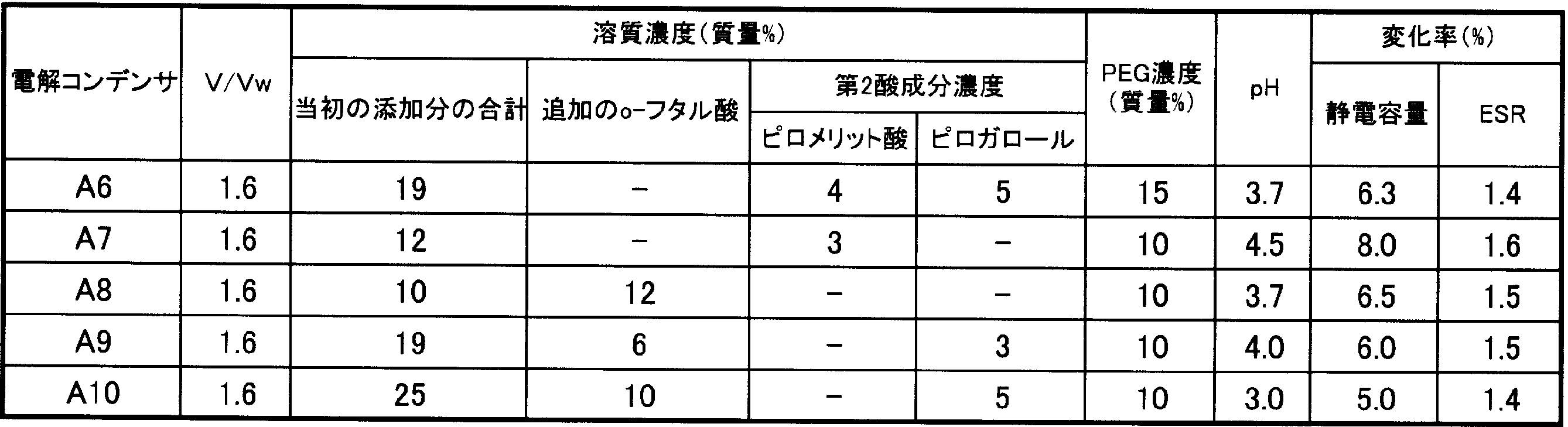
- Example 6 Similar to Example 1 except that 4% by mass of pyromellitic acid and 5% by mass of pyrogallol were added instead of the additional o-phthalic acid (12% by mass) and the concentration of PEG was 15% by mass. Then, an electrolytic capacitor A6 was produced and evaluated in the same manner. The results are shown in Table 2.
- Example 7 Except that the initial solute concentration is 12% by mass without changing the initial equivalent ratio of the first acid component and the first base component, and that 3% by mass of pyromellitic acid is added instead of pyrogallol. In the same manner as in Example 1, an electrolytic capacitor A7 was produced and evaluated in the same manner. The results are shown in Table 2.
- Example 8 In the same manner as in Example 1 except that the initial solute concentration was 10% by mass without changing the initial equivalent ratio of the first acid component and the first base component, and that pyrogallol was not added.
- the electrolytic capacitor A8 was produced and evaluated in the same manner. The results are shown in Table 2.
- Example 9 An electrolytic capacitor A9 was produced and evaluated in the same manner as in Example 1 except that the concentration of additional o-phthalic acid was changed to 6% by mass. The results are shown in Table 2.
- Example 10 That the initial solute concentration was 25% by mass, the concentration of the additional o-phthalic acid was 10% by mass, and the original equivalent ratio of the first acid component and the first base component was not changed;
- An electrolytic capacitor A10 was produced and evaluated in the same manner as in Example 1 except that the concentration of pyrogallol was changed to 5% by mass. The results are shown in Table 2.
- Example 11 An electrolytic capacitor A11 was produced and evaluated in the same manner as in Example 1 except that the formation voltage V was 35 volts and V / Vw was 1.4 and pyrogallol was not added. . The results are shown in Table 3. Comparative Example 3 An electrolytic capacitor B3 was produced and evaluated in the same manner as in Comparative Example 1 except that the formation voltage V was 35 volts and V / Vw was 1.4. The results are shown in Table 3.
- Example 12 In place of triethylamine as the first base component, an amidine 1,2,3,4-tetramethylimidazolinium was used, and the initial equivalent ratio between the first acid component and the first base component was changed. Instead, an electrolytic capacitor A12 was produced and evaluated in the same manner as in Example 1 except that the initial solute concentration was 14% by mass. The results are shown in Table 4. The concentration of the acid component was 22.2% by mass, and the concentration of the base component was 6.8% by mass. Example 13 An electrolytic capacitor A13 was produced and evaluated in the same manner as in Example 12 except that PEG was not added. The results are shown in Table 4.
- the present invention can be applied to a hybrid electrolytic capacitor comprising a solid electrolyte and an electrolytic solution.
Abstract
コンデンサ素子と、電解液と、を備える電解コンデンサであって、前記コンデンサ素子は、化成皮膜を有する陽極体と、前記化成皮膜に接触した固体電解質と、を備え、前記電解液は、溶媒と、溶質と、を含み、前記溶媒は、ラクトン化合物、グリコール化合物およびスルホン化合物よりなる群から選ばれる少なくとも1種を含み、前記溶質は、第1酸成分としてベンゼンジカルボン酸およびその誘導体の少なくとも1種と、塩基成分としてアミンおよびアミジンの少なくとも1種と、を含み、前記電解液における前記溶質の濃度は、15質量%以上、40質量%以下であり、前記化成皮膜を形成するために前記陽極体に印加される化成電圧Vボルトと、前記電解コンデンサの定格電圧Vwボルトとの比:V/Vwは、1.7以下である、電解コンデンサ。
Description
本発明は、固体電解質と電解液とを具備する電解コンデンサに関する。
小型かつ大容量でESR(等価直列抵抗)の低いコンデンサとして、固体電解質と電解液とを具備する、いわゆるハイブリッド型の電解コンデンサが有望視されている。例えば、特許文献1には、陽極体の表面に酸化皮膜(化成皮膜)が形成された、ハイブリッド型の電解コンデンサが開示されている。
しかし、従来のハイブリッド型の電解コンデンサでは、化成電圧と定格電圧との比を低くした場合、静電容量および等価直列抵抗(ESR)を十分に維持できなかった。
上記に鑑み、本発明の第一局面は、コンデンサ素子と、電解液と、を備える電解コンデンサであって、前記コンデンサ素子は、化成皮膜を有する陽極体と、前記化成皮膜に接触した固体電解質と、を備え、前記電解液は、溶媒と、溶質と、を含み、前記溶媒は、ラクトン化合物、グリコール化合物およびスルホン化合物よりなる群から選ばれる少なくとも1種を含み、前記溶質は、第1酸成分としてベンゼンジカルボン酸およびその誘導体の少なくとも1種と、塩基成分としてアミンおよびアミジンの少なくとも1種と、を含み、前記電解液における前記溶質の濃度は、15質量%以上、40質量%以下であり、前記化成皮膜を形成するために前記陽極体に印加される化成電圧Vボルトと、前記電解コンデンサの定格電圧Vwボルトとの比:V/Vwは、1.7以下である、電解コンデンサに関する。
また、本発明の第二局面は、コンデンサ素子と、電解液と、を備える電解コンデンサであって、前記コンデンサ素子は、化成皮膜を有する陽極体と、前記化成皮膜に接触した固体電解質と、を備え、前記電解液は、溶媒と、溶質と、を含み、前記溶媒は、ラクトン化合物、グリコール化合物およびスルホン化合物よりなる群から選ばれる少なくとも1種を含み、前記溶質は、第1酸成分として有機酸と無機酸との複合化合物およびその誘導体の少なくとも1種と、塩基成分としてアミンおよびアミジンの少なくとも1種と、を含み、前記電解液における前記溶質の濃度は、10質量%以上、40質量%以下であり、前記化成皮膜を形成するために前記陽極体に印加される化成電圧Vボルトと、前記電解コンデンサの定格電圧Vwボルトとの比:V/Vwは、1.7以下である、電解コンデンサに関する。
本発明によれば、静電容量および等価直列抵抗(ESR)を十分に維持できる、ハイブリッド型の電解コンデンサを提供することができる。
[第1の実施形態]
本実施形態に係る電解コンデンサは、コンデンサ素子と、電解液と、を備える。コンデンサ素子は、化成皮膜を有する陽極体と、化成皮膜に接触した固体電解質と、を備える。
本実施形態に係る電解コンデンサは、コンデンサ素子と、電解液と、を備える。コンデンサ素子は、化成皮膜を有する陽極体と、化成皮膜に接触した固体電解質と、を備える。
ハイブリッド型の電解コンデンサにおいて、固体電解質と化成皮膜とは接触している。よって、リーク電流を低減するために、従来、化成電圧Vを電解コンデンサの定格電圧Vwの2倍程度の高い値に設定して、十分な厚みの化成皮膜を形成している。そのため、ハイブリッド型の電解コンデンサにおいて、定格電圧Vwと化成電圧Vとの比(V/Vw)を小さくして、電解コンデンサの静電容量を高めたり、あるいは、電解コンデンサを小型化することは困難であった。
そこで、発明者らが鋭意検討した結果、電解液を特定の組成にすることで、定格電圧Vwと化成電圧Vとの比(V/Vw)を小さくした場合においても、ハイブリッド型電解コンデンサの静電容量およびESRを維持できることが判明した。
第1に、特定の溶質を用いるとともに、その含有量を特定の範囲とする。具体的には、第1酸成分としてベンゼンジカルボン酸およびその誘導体の少なくとも1種と、塩基成分としてアミンおよびアミジンの少なくとも1種と、を含む溶質を用いる。そして、電解液に含まれる溶質の濃度、つまり、第1酸成分を含む酸成分と塩基成分との合計の濃度を、15質量%以上、40質量%未満にする。
第2に、特定の溶媒を用いる。具体的には、溶媒として、γ-ブチロラクトン、エチレングリコールおよびスルホランよりなる群から選ばれる少なくとも1種を用いる。
電解液を上記のような組成にすることにより、溶質に含まれる第1酸成分は、陽極体の欠陥付近まで到達し易くなる。そのため、化成皮膜の自己修復性能が向上し、静電容量およびESRを維持することができる。よって、化成電圧Vボルトと定格電圧Vwボルトとの比:V/Vwを、1.7以下にすることができる。
なお、電解液に高分子成分を含ませる場合、高分子成分の濃度は、1質量%以上、15質量%以下にする。これにより、電解液に高分子成分を含む場合であっても、第1酸成分の移動は妨げられ難いため、上記効果が得られる。
化成皮膜は、酸性の水溶液(以下、化成液)中に浸漬した状態で、陽極体に所定の化成電圧を印加する方法(以下、第1の方法)により形成される皮膜に限定されない。例えば、化成皮膜は、化成液中に浸漬した状態で、陽極体を熱処理することにより形成されてもよい(以下、第2の方法)。第1の方法で化成皮膜を形成すると、化成電圧に応じた厚みTを有する化成皮膜が形成される。つまり、化成皮膜の厚みTから、化成電圧が求められる。第2の方法で化成皮膜を形成した場合にも、その厚みTから、当該化成皮膜を、第1の方法で形成する場合に必要な化成電圧が求められる。すなわち、化成電圧Vとは、厚みTの化成皮膜を形成するために陽極体に印加された電圧、および、厚みTの化成皮膜を形成するために必要な電圧を含む。
定格電圧Vwは、定格として定められている上限の電圧であり、電解コンデンサの電極間にかけられる電圧の最大値である。
[電解液]
電解液は、溶媒および溶質を含む。
[電解液]
電解液は、溶媒および溶質を含む。
電解液のpHは4.5以下が好ましい。電解液のpHを4.5以下とすることで、固体電解質の脱ドープ現象が抑制され易くなる。そのため、ESRを維持することができる。電解液のpHは4以下がより好ましく、3.8以下が特に好ましい。また、電解液のpHは2以上が好ましい。
電解液の電導度は、0.01mS/cm以上、3mS/cm以下であることが好ましい。この場合、化成電圧Vボルトと定格電圧Vwボルトとの比:V/Vwを1.7以下とする際に、自己修復性能がさらに向上され易くなる。
(溶媒)
溶媒は、γ-ブチロラクトン(γBL)、エチレングリコール(EG)およびスルホラン(SL)よりなる群から選択される少なくとも1種(以下、主溶媒)を含むことが好ましい。主溶媒としては、EG以外のグリコール化合物、SL以外のスルホン化合物、γBL以外のラクトン化合物を用いてもよい。EG以外のグリコール化合物としては、ジエチレングリコール、トリエチレングリコール、プロピレングリコールなどを用いることができる。SL以外のスルホン化合物としては、ジメチルスルホキシド、ジエチルスルホキシドなどを用いることができる。γBL以外のラクトン化合物としては、γ-バレロラクトンなどを用いることができる。溶媒に含まれる主溶媒(例えば、γBL、EGおよびSLの合計)の割合は、50質量%以上が好ましく、60質量%以上がより好ましく、70質量%以上がさらに好ましい。
溶媒は、主溶媒以外の溶媒(以下、副溶媒)として、カーボネート化合物、1価または3価以上のアルコールなどを含むことができる。カーボネート化合物としては、ジメチルカーボネート(DMC)、ジエチルカーボネート(DEC)、エチルメチルカーボネート(EMC)、エチレンカーボネート(EC)、プロピレンカーボネート(PC)、フルオロエチレンカーボネート(FEC)などを用いることができる。アルコールとしては、例えばグリセリンやポリグリセリンを用いることができる。これらは単独で用いてもよく、複数種を組み合わせて用いてもよい。
(溶質)
溶質の濃度は、15質量%以上、40質量%以下である。溶質の濃度は、20質量%以上、40質量%以下であることがより好ましく、20質量%以上、35質量%以下であることが特に好ましい。
(溶質)
溶質の濃度は、15質量%以上、40質量%以下である。溶質の濃度は、20質量%以上、40質量%以下であることがより好ましく、20質量%以上、35質量%以下であることが特に好ましい。
溶質の濃度は、酸成分の濃度と、塩基成分の濃度との合計である。酸成分とは、第1酸成分、および、第1酸成分以外の第2酸成分を含む。塩基成分とは、アミンおよび/またはアミジン(以下、第1塩基成分)、および、第1塩基成分以外の第2塩基成分を含む。
溶質は、第1酸成分としてベンゼンジカルボン酸およびその誘導体の少なくとも1種を含む。ベンゼンジカルボン酸としては、o-フタル酸、m-フタル酸、p-フタル酸であってもよい。ベンゼンジカルボン酸の誘導体としては、例えば、スルホ基を有する3-スルホフタル酸、3,5-ジスルホフタル酸、4-スルホイソフタル酸、2-スルホテレフタル酸、2-メチル-5-スルホテレフタル酸等が挙げられる。なかでも、o-フタル酸が好ましい。
電解液中に含まれる第1酸成分の濃度は、解離し易い点で、5質量%以上が好ましく、15質量%以上がより好ましい。また、第1酸成分の濃度は、35質量%以下が好ましく、30質量%以下がより好ましい。
酸成分は、第1酸成分以外の第2酸成分を含んでもよい。
第2酸成分として用いられる有機酸としては、例えば、ポリカルボン酸、モノカルボン酸、多価フェノール等が挙げられる。
ポリカルボン酸としては、脂肪族ポリカルボン酸:([飽和ポリカルボン酸、例えばシュウ酸、マロン酸、コハク酸、グルタル酸、アジピン酸、ピメリン酸、スベリン酸、アゼライン酸、セバチン酸、1,6-デカンジカルボン酸、5,6-デカンジカルボン酸]、[不飽和ポリカルボン酸、例えばマレイン酸、フマル酸、イコタン酸])、芳香族ポリカルボン酸:(例えばトリメリット酸、ピロメリット酸)、脂環式ポリカルボン酸:(例えばシクロヘキサン-1,2-ジカルボン酸、シクロヘキセン-1,2-ジカルボン酸等)が挙げられる。
モノカルボン酸としては、脂肪族モノカルボン酸(炭素数1~30):([飽和モノカルボン酸、例えばギ酸、酢酸、プロピオン酸、酪酸、イソ酪酸、吉草酸、カプロン酸、エナント酸、カプリル酸、ペラルゴン酸、ラウリル酸、ミリスチン酸、ステアリン酸、ベヘン酸]、[不飽和モノカルボン酸、例えばアクリル酸、メタクリル酸、オレイン酸])、芳香族モノカルボン酸:(例えば安息香酸、ケイ皮酸、ナフトエ酸)、オキシカルボン酸:(例えばサリチル酸、マンデル酸、レゾルシン酸)、これらの内で好ましいのは電導度が高く熱的にも安定な、マレイン酸、安息香酸、ピロメリット酸、レゾルシン酸である。
多価フェノールとしては、カテコール、レゾルシノール、ヒドロキノン、ピロガロール、フロログルシン等が挙げられる。
第2酸成分として用いられる無機酸としては、炭素化合物、水素化合物、ホウ素化合物、硫黄化合物、窒素化合物、リン化合物が挙げられる。代表的な無機酸の例として、リン酸、亜リン酸、次亜リン酸、アルキル燐酸エステル、ホウ酸、ホウフッ酸、4フッ化ホウ酸、6フッ化リン酸、ベンゼンスルホン酸、ナフタレンスルホン酸などが挙げられる。
第2酸成分として、有機酸と無機酸の複合化合物を用いてもよい。複合化合物としては、例えば、ボロジグリコール酸、ボロジ蓚酸、ボロジサリチル酸などが挙げられる。
なかでも、自己修復性能がさらに向上する点で、第2酸成分としては、芳香族ポリカルボン酸、多価フェノールおよびオキシカルボン酸よりなる群から選択される少なくとも1種が好ましい。
第2酸成分の濃度は、3質量%以上が好ましく、5質量%以上がより好ましい。また、第2酸成分の濃度は、25質量%以下が好ましく、15質量%以下がより好ましい。
溶質は、第1塩基成分としてアミンおよびアミジンの少なくとも1種を含む。
アミンは、第1級アミン、第2級アミンおよび第3級アミンであってもよい。各アミンは、脂肪族アミン、芳香族アミン、複素環式アミンであってもよい。なかでも、ESRを長期的に安定化する効果が高められる点で、3級アミンが好ましい。
3級アミンとしては、トリアルキルアミン類(トリメチルアミン、ジメチルエチルアミン、メチルジエチルアミン、トリエチルアミン、ジメチルn-プロピルアミン、ジメチルイソプロピルアミン、メチルエチルn-プロピルアミン、メチルエチルイソプロピルアミン、ジエチルn-プロピルアミン、ジエチルイソプロピルアミン、トリn-プロピルアミン、トリイソプロピルアミン、トリn-ブチルアミン、トリt-ブチルアミンなど)、フェニル基含有アミン(ジメチルフェニルアミン、メチルエチルフェニルアミン、ジエチルフェニルアミンなど)が挙げられる。なかでも、電導度が高い点で、トリメチルアミン、ジメチルエチルアミン、メチルジエチルアミン、トリエチルアミンなどのトリアルキルアミンが好ましい。
アミジンとしては、電導度が高い点で、アルキル置換アミジン基を有する化合物が好ましい。アルキル置換アミジン基を有する化合物としては、例えば、イミダゾール化合物、ベンゾイミダゾール化合物、脂環式アミジン化合物(ピリミジン化合物、イミダゾリン化合物)が挙げられる。具体的には、1,8-ジアザビシクロ[5,4,0]ウンデセン-7、1,5-ジアザビシクロ[4,3,0]ノネン-5、1,2-ジメチルイミダゾリニウム、1,2,4-トリメチルイミダゾリン、1-メチル-2-エチル-イミダゾリン、1,4-ジメチル-2-エチルイミダゾリン、1-メチル-2-ヘプチルイミダゾリン、1-メチル-2-(3’ヘプチル)イミダゾリン、1-メチル-2-ドデシルイミダゾリン、1,2-ジメチル-1,4,5,6-テトラヒドロピリミジン、1-メチルイミダゾール、1-メチルベンゾイミダゾール、1-メチル-1,8-ジアザビシクロ[5,4,0]ウンデセン-7、1-メチル-1,5-ジアザビシクロ[4,3,0]ノネン-5、1,2,3-トリメチルイミダゾリニウム、1,2,3,4-テトラメチルイミダゾリニウム、1,2-ジメチル-3-エチル-イミダゾリニウム、1,3,4-トリメチル-2-エチルイミダゾリニウム、1,3-ジメチル-2-ヘプチルイミダゾリニウム、1,3-ジメチル-2-(3’ヘプチル)イミダゾリニウム、1,3-ジメチル-2-ドデシルイミダゾリニウム、1,2,3-トリメチル-1,4,5,6-テトラヒドロピリミジウム、1,3-ジメチルイミダゾリウム、1-メチル-3-エチルイミダゾリウム、1,3-ジメチルベンゾイミダゾリウムが挙げられる。
電解液中に含まれる第1塩基成分の濃度は、3.5質量%以上が好ましく、5質量%以上がより好ましい。また、第1塩基成分の濃度は、20質量%以下が好ましく、10質量%以下がより好ましい。
電解液中にアミンが含まれる場合、その濃度は、3.5質量%以上が好ましく、5質量%以上がより好ましい。また、アミンの濃度は、20質量%以下が好ましく、10質量%以下がより好ましい。
電解液中にアミジンが含まれる場合、その濃度は、3.5質量%以上が好ましく、5質量%以上がより好ましい。また、アミジンの濃度は、20質量%以下が好ましく、10質量%以下がより好ましい。
塩基成分は、第1塩基成分以外の第2塩基成分を含んでいてもよい。
第2塩基成分としては、例えば、アンモニア、第4級アンモニウム化合物が挙げられる。第2塩基成分の濃度は0.1質量%以上が好ましく、3質量%以上がより好ましい。また、第2塩基成分の濃度は、20質量%以下が好ましく、10質量%以下がより好ましい。
導電性高分子に含まれるドーパントが脱ドープすることを効果的に抑制する観点から、酸成分は、塩基成分より当量比で過剰であることが好ましい。例えば、塩基成分に対する酸成分の当量比は、1~30であることが望ましい。
(高分子成分)
電解液は高分子成分を含んでもよい。高分子成分は、電解液の蒸散抑制および耐電圧向上のために含まれる。
(高分子成分)
電解液は高分子成分を含んでもよい。高分子成分は、電解液の蒸散抑制および耐電圧向上のために含まれる。
高分子成分は特に限定されない。高分子成分としては、例えば、ポリアルキレングリコール、ポリアルキレングリコールの誘導体、多価アルコールの水酸基の少なくとも1つがポリアルキレングリコール(誘導体含む)に置換された化合物等が挙げられる。具体的には、ポリエチレングリコール、ポリエチレングリコールグリセリルエーテル、ポリエチレングリコールジグリセリルエーテル、ポリエチレングリコールソルビトールエーテル、ポリプロピレングリコール、ポリプロピレングリコールグリセリルエーテル、ポリプロピレングリコールジグリセリルエーテル、ポリプロピレングリコールソルビトールエーテル、ポリブチレングリコール等が挙げられる。これらは単独で用いてもよく、2種以上を混合して用いてもよい。
上記のポリアルキレングリコールは、共重合体(ランダム共重合体、ブロック共重合体、あるいは、ランダムブロック共重合体等)であってもよい。例えば、エチレングリコールとプロピレングリコールとの共重合体、エチレングリコールとブチレングリコールとの共重合体、プロピレングリコールとブチレングリコールとの共重合体等が挙げられる。
高分子成分の重量平均分子量は200以上が好ましい。溶媒に対する溶解性の観点から、高分子成分の重量平均分子量は20,000以下が好ましく、5000以下がより好ましい。
電解液における高分子成分の濃度は、1質量%以上、15質量%以下が好ましい。高分子成分の濃度がこの範囲であれば、電解液の蒸散が抑制されるとともに、第1酸成分の移動が妨げられない。よって、化成皮膜の自己修復性能が向上する。電解液における高分子成分の濃度は、1質量%以上、10質量%以下がより好ましい。
(固体電解質)
固体電解質は、例えば、マンガン化合物や導電性高分子を含む。導電性高分子としては、例えば、ポリピロール、ポリチオフェン、ポリアニリンおよびこれらの誘導体などを用いることができる。固体電解質は、ドーパントを含む。より具体的には、固体電解質は、導電性高分子としてポリ(3,4-エチレンジオキシチオフェン)(PEDOT)、および、ドーパントとしてポリスチレンスルホン酸(PSS)を含むことができる。
(固体電解質)
固体電解質は、例えば、マンガン化合物や導電性高分子を含む。導電性高分子としては、例えば、ポリピロール、ポリチオフェン、ポリアニリンおよびこれらの誘導体などを用いることができる。固体電解質は、ドーパントを含む。より具体的には、固体電解質は、導電性高分子としてポリ(3,4-エチレンジオキシチオフェン)(PEDOT)、および、ドーパントとしてポリスチレンスルホン酸(PSS)を含むことができる。
固体電解質は、モノマーとドーパントとを含有する溶液を化成皮膜に付与し、その場で、化学重合もしくは電解重合させる方法で形成してもよい。ただし、優れた耐電圧特性を期待できる点で、導電性高分子を化成皮膜に付与する方法により、固体電解質を形成することが好ましい。すなわち、固体電解質は、液状成分と、液状成分に分散する導電性高分子とドーパントとを含む高分子分散体を、化成皮膜に含浸させた後、液状成分を揮発させることにより形成されたものであることが好ましい。
高分子分散体に含まれる導電性高分子の濃度は、0.5~10質量%であることが好ましい。また、導電性高分子の平均粒径D50は、例えば0.01~0.5μmであることが好ましい。ここで、平均粒径D50は、動的光散乱法による粒度分布測定装置により求められる体積粒度分布におけるメディアン径である。
(化成電圧Vおよび定格電圧Vw)
厚みTの化成皮膜を形成するために陽極体に印加される化成電圧Vと、電解コンデンサの定格電圧Vwとの比:V/Vwは、1.7以下である。V/Vwは、1.6以下であってもよい。リーク電流の増大抑制の観点から、V/Vwは、1.4以上が好ましく、1.5以上がより好ましい。
(化成電圧Vおよび定格電圧Vw)
厚みTの化成皮膜を形成するために陽極体に印加される化成電圧Vと、電解コンデンサの定格電圧Vwとの比:V/Vwは、1.7以下である。V/Vwは、1.6以下であってもよい。リーク電流の増大抑制の観点から、V/Vwは、1.4以上が好ましく、1.5以上がより好ましい。
化成電圧Vは特に限定されず、定格電圧Vwに応じて、V/Vwが1.7以下になるように、適宜設定すればよい。化成皮膜の厚みTは、化成電圧Vに比例して増加する。例えば、化成電圧Vが17ボルトの場合、化成皮膜の厚みTは24nmになる。化成電圧Vが170ボルトの場合、化成皮膜の厚みTは238nmになる。言い換えれば、化成皮膜の厚みTが238nmの場合、陽極体に印加された、あるいは必要な化成電圧Vは、170ボルトである。
定格電圧Vwも特に限定されないが、100V以下(すなわち、化成皮膜の厚みTが238nm以下)の場合に、本発明の効果が特に発揮され易い。特に、化成皮膜がさらに薄くなる70ボルト以下の定格電圧Vwの場合、本発明の効果はさらに発揮される。
以下、本発明を実施形態に基づいて、より具体的に説明する。ただし、以下の実施形態は本発明を限定するものではない。
図1は、本実施形態に係る電解コンデンサの断面模式図であり、図2は、同電解コンデンサに係るコンデンサ素子の一部を展開した概略図である。
電解コンデンサは、例えば、コンデンサ素子10と、コンデンサ素子10を収容する有底ケース11と、有底ケース11の開口を塞ぐ封止部材12と、封止部材12を覆う座板13と、封止部材12から導出され、座板13を貫通するリード線14A、14Bと、リード線とコンデンサ素子10の電極とを接続するリードタブ15A、15Bと、電解液(不図示)とを備える。有底ケース11の開口端近傍は、内側に絞り加工されており、開口端は封止部材12にかしめるようにカール加工されている。
コンデンサ素子10は、図2に示すような巻回体から作製される。巻回体は、リードタブ15Aと接続された陽極体21と、リードタブ15Bと接続された陰極体22と、セパレータ23とを備える。巻回体は、陽極体21と陰極体22との間に固体電解質が形成されていない半製品である。
陽極体21および陰極体22は、セパレータ23を介して巻回されている。巻回体の最外周は、巻止めテープ24により固定される。なお、図2は、巻回体の最外周を止める前の、一部が展開された状態を示している。
陽極体21は、表面が凹凸を有するように粗面化された金属箔を具備し、凹凸を有する金属箔上に化成皮膜が形成されている。化成皮膜の表面の少なくとも一部に、固体電解質が付着している。固体電解質は、陰極体22の表面および/またはセパレータ23の表面の少なくとも一部を被覆していてもよい。固体電解質が形成されたコンデンサ素子10は、電解液とともに有底ケース11に収容される。
≪電解コンデンサの製造方法≫
以下、本実施形態に係る電解コンデンサの製造方法の一例について、工程ごとに説明する。
(i)化成皮膜を有する陽極体21を準備する工程
まず、陽極体21の原料である金属箔を準備する。金属の種類は特に限定されないが、化成皮膜の形成が容易である点から、アルミニウム、タンタル、ニオブなどの弁作用金属または弁作用金属を含む合金を用いることが好ましい。
≪電解コンデンサの製造方法≫
以下、本実施形態に係る電解コンデンサの製造方法の一例について、工程ごとに説明する。
(i)化成皮膜を有する陽極体21を準備する工程
まず、陽極体21の原料である金属箔を準備する。金属の種類は特に限定されないが、化成皮膜の形成が容易である点から、アルミニウム、タンタル、ニオブなどの弁作用金属または弁作用金属を含む合金を用いることが好ましい。
次に、金属箔の表面を粗面化する。粗面化により、金属箔の表面に、複数の凹凸が形成される。粗面化は、金属箔をエッチング処理することにより行うことが好ましい。エッチング処理は、例えば直流電解法や交流電解法により行えばよい。
次に、粗面化された金属箔の表面に、厚みTの化成皮膜を形成する。形成方法は特に限定されないが、金属箔を化成処理することにより形成することができる。化成処理では、例えば、金属箔をアジピン酸アンモニウム溶液などの化成液に浸漬し、熱処理する。また、金属箔を化成液に浸漬し、電圧を印加してもよい。
通常、量産性の観点から、大判の弁作用金属などの箔(金属箔)に対して、粗面化処理および化成処理が行われる。その場合、処理後の箔を所望の大きさに裁断することによって、陽極体21が準備される。
(ii)陰極体22を準備する工程
陰極体22には、陽極体21と同様、金属箔を用いることができる。金属の種類は特に限定されないが、アルミニウム、タンタル、ニオブなどの弁作用金属または弁作用金属を含む合金を用いることが好ましい。必要に応じて、陰極体22の表面を粗面化してもよい。
(ii)陰極体22を準備する工程
陰極体22には、陽極体21と同様、金属箔を用いることができる。金属の種類は特に限定されないが、アルミニウム、タンタル、ニオブなどの弁作用金属または弁作用金属を含む合金を用いることが好ましい。必要に応じて、陰極体22の表面を粗面化してもよい。
また、陰極体22の表面にチタンやカーボンを含む層を形成してもよい。
(iii)巻回体の作製
次に、陽極体21、陰極体22およびセパレータ23を用いて、図2に示すよう巻回体を作製する。最外層に位置する陰極体22の端部を巻止めテープ24で固定する。陽極体21を大判の金属箔を裁断することによって準備した場合、陽極体21の裁断面に化成皮膜を設けるために、巻回体に対し、さらに化成処理を行ってもよい。セパレータ23としては、例えば、セルロース、ポリエチレンテレフタレート、ビニロン、アラミド繊維などを主成分とする不織布を用いることができる。
(iv)コンデンサ素子10を形成する工程
次に、巻回体に含まれる化成皮膜の表面に固体電解質を付着させ、コンデンサ素子10が作製される。固体電解質が導電性高分子を含む場合、重合液を用いて、その場で化学重合もしくは電解重合により合成した導電性高分子を、化成皮膜に付着させてもよい。重合液は、モノマーもしくはオリゴマー、ドーパントなどを含有する溶液である。化学重合の場合、重合液に酸化剤が添加される。また、予め合成された導電性高分子を化成皮膜に付着させてもよい。モノマーやオリゴマーには、ピロール、アニリン、チオフェン、これらの誘導体などが用いられる。
予め合成された導電性高分子としては、高分子分散体を用いることが好ましい。高分子分散体は、液状成分と、液状成分に分散する導電性高分子と、ドーパントと、を含む。高分子分散体を化成皮膜の表面に付与する方法としては、例えば、巻回体を高分子分散体に含浸させ、乾燥させる方法が簡易で好ましい。高分子分散体は、導電性高分子としてPEDOTを含み、ドーパントとしてPSSを含むことが好ましい。
高分子分散体を化成皮膜の表面に付与する工程と、巻回体を乾燥させる工程とは、2回以上繰り返してもよい。これらの工程を複数回行うことにより、化成皮膜に対する固体電解質の被覆率を高めることができる。
(v)コンデンサ素子10に電解液を含浸させる工程
次に、コンデンサ素子10に、電解液を含浸させる。コンデンサ素子10に電解液を含浸させる方法は特に限定されない。
(vi)コンデンサ素子を封止する工程
次に、コンデンサ素子10を有底ケース11に収納する。有底ケース11の材料としては、アルミニウム、ステンレス鋼、銅、鉄、真鍮などの金属あるいはこれらの合金を用いることができる。その後、有底ケース11の開口端近傍に、横絞り加工を施し、開口端を封止部材12に加締めてカール加工する。そして、カール部分に座板13を配置することによって、図1に示すような電解コンデンサが完成する。その後、定格電圧を印加しながら、エージング処理を行ってもよい。
上記の実施形態では、巻回型の電解コンデンサについて説明したが、本発明の適用範囲は上記に限定されず、他の電解コンデンサ、例えば、陽極体として金属の焼結体を用いるチップ型の電解コンデンサや、金属板を陽極体として用いる積層型の電解コンデンサにも適用することができる。
[第2の実施形態]
本発明の第2の実施形態に係る電解コンデンサについて説明する。第2の実施形態による電解コンデンサは、第1酸成分として、有機酸と無機酸との複合化合物およびその誘導体のうち少なくとも1種を含む点を除き、第1の実施形態と同様の構成を有するので、重複する内容については説明を省略する。
[第2の実施形態]
本発明の第2の実施形態に係る電解コンデンサについて説明する。第2の実施形態による電解コンデンサは、第1酸成分として、有機酸と無機酸との複合化合物およびその誘導体のうち少なくとも1種を含む点を除き、第1の実施形態と同様の構成を有するので、重複する内容については説明を省略する。
本実施形態では、第1酸成分としての複合化合物が、ボロジサリチル酸、ボロジグリコール酸、及びボロジシュウ酸からなる群から選択される1種以上を含むことが好ましい。
電解液に含まれる溶質の濃度、つまり、第1酸成分を含む酸成分と塩基成分との合計の濃度を、10質量%以上、40質量%未満にする。溶質の濃度は、15質量%以上、35質量%以下であることがより好ましく、20質量%以上、35質量%以下であることが特に好ましい。第1酸成分として複合化合物を用いた場合、電解液中での解離度が高いため、溶質の濃度が10質量%以上であっても第1の実施形態と同様に第1酸成分が陽極体の欠陥付近まで到達し易くなり、化成皮膜の自己修復性能を向上できる。また、複合化合物は耐熱性に優れるため複合化合物を含む電解液はpHを保ち易く、導電性高分子からの脱ドープを抑制できるのでESRを維持できる。
[実施例]
以下、実施例に基づいて、本発明をより詳細に説明するが、本発明は実施例に限定されるものではない。
《実施例1》
定格電圧Vw:25ボルト、定格静電容量33μFの巻回型の電解コンデンサ(Φ10mm×L(長さ)10mm)を以下の要領で作製した。
(陽極体の準備)
厚さ100μmのアルミニウム箔にエッチング処理を行い、アルミニウム箔の表面を粗面化した。粗面化されたアルミニウム箔の表面を化成処理して化成皮膜を形成した。化成処理は、アジピン酸アンモニウム溶液にアルミニウム箔を浸漬し、アルミニウム箔に40ボルトの電圧を印加して行った。その後、アルミニウム箔を6mm×120mmに裁断して陽極体を準備した。V/Vwを1.6とした。化成皮膜の厚みTは55nmであった。
(陰極体の準備)
厚さ50μmのアルミニウム箔にエッチング処理を行い、アルミニウム箔の表面を粗面化した。その後、アルミニウム箔を6mm×120mmに裁断して陰極体を準備した。
(巻回体の作製)
陽極体および陰極体に陽極リードタブおよび陰極リードタブを接続し、リードタブを巻き込みながら陽極体と陰極体とをセパレータを介して巻回した。巻回体から突出する各リードタブの端部に陽極リード線および陰極リード線をそれぞれ接続した。得られた巻回体に再度化成を行い、陽極体の切断された端部に化成皮膜を形成した。巻回体の外側表面の端部は巻止めテープで固定した。
(高分子分散体の調製)
3,4-エチレンジオキシチオフェンと、ポリスチレンスルホン酸(PSS、重量平均分子量10万)とを、イオン交換水に溶かし、混合溶液を調製した。混合溶液を撹拌しながら硫酸鉄(III)(酸化剤)を添加し、重合反応を行った。その後、反応液を透析し、
未反応モノマーおよび酸化剤を除去し、約5質量%のPSSがドープされたポリエチレンジオキシチオフェン(PEDOT/PSS)を含む高分子分散体を得た。
(固体電解質の形成)
減圧雰囲気(40kPa)中で、高分子分散体に巻回体を5分間浸漬し、その後、高分子分散体から巻回体を引き上げた。次に、高分子分散体を含浸した巻回体を、150℃の乾燥炉内で20分間乾燥させ、化成皮膜の少なくとも一部を被覆する固体電解質を形成した。
(電解液の含浸)
溶媒としてγ-ブチロラクトン(γBL)およびスルホランを準備した。この溶媒に、第1酸成分としてo-フタル酸を、第1塩基成分としてトリエチルアミンを、合計で19質量%の濃度、当量比(当初の当量比)1で溶解させた。上記で得られた溶液に、PEG(重量平均分子量300)を10質量%の濃度で溶解させた。最後に、o-フタル酸を12質量%追加するとともに、ピロガロール3質量%を加えて、電解液のpHを3.5にして、電解液を調製した。減圧雰囲気(40kPa)中で、電解液にコンデンサ素子を5分間浸漬した。なお、各成分の濃度は、いずれも得られる電解液の質量を100%とした場合の割合である。酸成分の濃度は、28.2質量%であり、塩基成分の濃度は、5.8質
量%であった。
(コンデンサ素子の封止)
電解液を含浸させたコンデンサ素子を封止して、図1に示すような電解コンデンサ(A1)を完成させた。その後、定格電圧Vwを印加しながら、95℃で90分のエージングを行った。
<評価>
コンデンサA1について、エージング後および2500時間後の静電容量およびESRを測定した。2500時間後の値をエージング後の値で除して、変化率を算出した。結果を表1に示す。
《実施例2~5》
PEGの濃度を表1に示すように変えたこと以外、実施例1と同様にして、電解コンデンサA2~A5を作製し、同様に評価した。結果を表1に示す。
《比較例1》
第1酸成分と第1塩基成分との当初の当量比を変えずに、当初の溶質濃度を10質量%としたこと、追加のo-フタル酸の濃度を4質量%にしたこと、および、ピロガロールを添加しなかった(溶質の合計の濃度を14質量%にした)こと以外、実施例1と同様にして、電解コンデンサB1を作製し、同様に評価した。結果を表1に示す。酸成分の濃度は、10.9質量%であり、塩基成分の濃度は、3.1質量%であった。
《比較例2》
化成電圧Vを45ボルトにして、V/Vwを1.8としたこと以外、比較例1と同様にして、電解コンデンサB2を作製し、同様に評価した。結果を表1に示す。

《実施例6》
追加のo-フタル酸(12質量%)に替えて、ピロメリット酸4質量%およびピロガロール5質量%を加えたこと、および、PEGの濃度を15質量%にしたこと以外、実施例1と同様にして、電解コンデンサA6を作製し、同様に評価した。結果を表2に示す。
《実施例7》
第1酸成分と第1塩基成分との当初の当量比を変えずに、当初の溶質濃度を12質量%としたこと、および、ピロガロールに替えて、ピロメリット酸を3質量%添加したこと以外、実施例1と同様にして、電解コンデンサA7を作製し、同様に評価した。結果を表2に示す。
《実施例8》
第1酸成分と第1塩基成分との当初の当量比を変えずに、当初の溶質濃度を10質量%としたこと、および、ピロガロールを添加しなかったこと以外、実施例1と同様にして、電解コンデンサA8を作製し、同様に評価した。結果を表2に示す。
《実施例9》
追加のo-フタル酸の濃度を6質量%にしたこと以外、実施例1と同様にして、電解コンデンサA9を作製し、同様に評価した。結果を表2に示す。
《実施例10》
第1酸成分と第1塩基成分との当初の当量比を変えずに、当初の溶質濃度を25質量%としたこと、追加のo-フタル酸の濃度を10質量%にしたこと、および、ピロガロールの濃度を5質量%にしたこと以外、実施例1と同様にして、電解コンデンサA10を作製し、同様に評価した。結果を表2に示す。
《実施例11》
化成電圧Vを35ボルトにして、V/Vwを1.4としたこと、および、ピロガロールを添加しなかったこと以外、実施例1と同様にして、電解コンデンサA11を作製し、同様に評価した。結果を表3に示す。
《比較例3》
化成電圧Vを35ボルトにして、V/Vwを1.4としたこと以外、比較例1と同様にして、電解コンデンサB3を作製し、同様に評価した。結果を表3に示す。
化成電圧Vを35ボルトにして、V/Vwを1.4としたこと、および、ピロガロールを添加しなかったこと以外、実施例1と同様にして、電解コンデンサA11を作製し、同様に評価した。結果を表3に示す。
《比較例3》
化成電圧Vを35ボルトにして、V/Vwを1.4としたこと以外、比較例1と同様にして、電解コンデンサB3を作製し、同様に評価した。結果を表3に示す。

《実施例12》
第1塩基成分としてトリエチルアミンに替えて、アミジンである1,2,3,4-テトラメチルイミダゾリニウムを用いたこと、および、第1酸成分と第1塩基成分との当初の当量比を変えずに、当初の溶質濃度を14質量%としたこと以外、実施例1と同様にして、電解コンデンサA12を作製し、同様に評価した。結果を表4に示す。酸成分の濃度は、22.2質量%であり、塩基成分の濃度は、6.8質量%であった。
《実施例13》
PEGを添加しなかったこと以外、実施例12と同様にして、電解コンデンサA13を作製し、同様に評価した。結果を表4に示す。
第1塩基成分としてトリエチルアミンに替えて、アミジンである1,2,3,4-テトラメチルイミダゾリニウムを用いたこと、および、第1酸成分と第1塩基成分との当初の当量比を変えずに、当初の溶質濃度を14質量%としたこと以外、実施例1と同様にして、電解コンデンサA12を作製し、同様に評価した。結果を表4に示す。酸成分の濃度は、22.2質量%であり、塩基成分の濃度は、6.8質量%であった。
《実施例13》
PEGを添加しなかったこと以外、実施例12と同様にして、電解コンデンサA13を作製し、同様に評価した。結果を表4に示す。

本発明は、固体電解質と電解液とを具備する、ハイブリッド型の電解コンデンサに適用することができる。
10:コンデンサ素子、11:有底ケース、12:封止部材、13:座板、14A,14B:リード線、15A,15B:リードタブ、21:陽極体、22:陰極体、23:セパレータ、24:巻止めテープ
Claims (11)
- コンデンサ素子と、電解液と、を備える電解コンデンサであって、
前記コンデンサ素子は、化成皮膜を有する陽極体と、前記化成皮膜に接触した固体電解質と、を備え、
前記電解液は、溶媒と、溶質と、を含み、
前記溶媒は、ラクトン化合物、グリコール化合物およびスルホン化合物よりなる群から選ばれる少なくとも1種を含み、
前記溶質は、第1酸成分としてベンゼンジカルボン酸およびその誘導体の少なくとも1種と、塩基成分としてアミンおよびアミジンの少なくとも1種と、を含み、
前記電解液における前記溶質の濃度は、15質量%以上、40質量%以下であり、
前記化成皮膜を形成するために前記陽極体に印加される化成電圧Vボルトと、前記電解コンデンサの定格電圧Vwボルトとの比:V/Vwは、1.7以下である、電解コンデンサ。 - 前記ベンゼンジカルボン酸は、o-フタル酸である、請求項1に記載の電解コンデンサ。
- コンデンサ素子と、電解液と、を備える電解コンデンサであって、
前記コンデンサ素子は、化成皮膜を有する陽極体と、前記化成皮膜に接触した固体電解質と、を備え、
前記電解液は、溶媒と、溶質と、を含み、
前記溶媒は、ラクトン化合物、グリコール化合物およびスルホン化合物よりなる群から選ばれる少なくとも1種を含み、
前記溶質は、第1酸成分として有機酸と無機酸との複合化合物およびその誘導体の少なくとも1種と、塩基成分としてアミンおよびアミジンの少なくとも1種と、を含み、
前記電解液における前記溶質の濃度は、10質量%以上、40質量%以下であり、
前記化成皮膜を形成するために前記陽極体に印加される化成電圧Vボルトと、前記電解コンデンサの定格電圧Vwボルトとの比:V/Vwは、1.7以下である、電解コンデンサ。 - 前記電解液のpHは、4.5以下である、請求項1~3いずれか一項に記載の電解コンデンサ。
- 前記電解液は、高分子成分をさらに含み、
前記電解液における前記高分子成分の濃度は、1質量%以上、15質量%以下である、請求項1~4いずれか一項に記載の電解コンデンサ。 - 前記定格電圧Vwは、100ボルト以下である、請求項1~5のいずれか一項に記載の電解コンデンサ。
- 前記電解液における前記塩基成分の濃度は、3.5質量%以上である、請求項1~6のいずれか一項に記載の電解コンデンサ。
- 前記溶質は、前記第1酸成分以外の第2酸成分をさらに含み、
前記電解液における前記第2酸成分の濃度は、3質量%以上である、請求項1~7のいずれか一項に記載の電解コンデンサ。 - 前記ラクトン化合物は、γ-ブチロラクトンである、請求項1~8のいずれか一項に記載の電解コンデンサ。
- 前記グリコール化合物は、エチレングリコールである、請求項1~9のいずれか一項に記載の電解コンデンサ。
- 前記スルホン化合物は、スルホランである、請求項1~10のいずれか一項に記載の電解コンデンサ。
Priority Applications (6)
| Application Number | Priority Date | Filing Date | Title |
|---|---|---|---|
| JP2019545671A JP7336686B2 (ja) | 2017-09-29 | 2018-09-28 | 電解コンデンサ |
| CN201880061703.1A CN111149183B (zh) | 2017-09-29 | 2018-09-28 | 电解电容器 |
| US16/810,105 US11195664B2 (en) | 2017-09-29 | 2020-03-05 | Electrolytic capacitor |
| US17/518,849 US11715605B2 (en) | 2017-09-29 | 2021-11-04 | Electrolytic capacitor |
| JP2023071003A JP2023089289A (ja) | 2017-09-29 | 2023-04-24 | 電解コンデンサ |
| US18/208,788 US20230326684A1 (en) | 2017-09-29 | 2023-06-12 | Electrolytic capacitor |
Applications Claiming Priority (2)
| Application Number | Priority Date | Filing Date | Title |
|---|---|---|---|
| JP2017191961 | 2017-09-29 | ||
| JP2017-191961 | 2017-09-29 |
Related Child Applications (1)
| Application Number | Title | Priority Date | Filing Date |
|---|---|---|---|
| US16/810,105 Continuation US11195664B2 (en) | 2017-09-29 | 2020-03-05 | Electrolytic capacitor |
Publications (1)
| Publication Number | Publication Date |
|---|---|
| WO2019065951A1 true WO2019065951A1 (ja) | 2019-04-04 |
Family
ID=65900901
Family Applications (1)
| Application Number | Title | Priority Date | Filing Date |
|---|---|---|---|
| PCT/JP2018/036209 WO2019065951A1 (ja) | 2017-09-29 | 2018-09-28 | 電解コンデンサ |
Country Status (4)
| Country | Link |
|---|---|
| US (3) | US11195664B2 (ja) |
| JP (2) | JP7336686B2 (ja) |
| CN (1) | CN111149183B (ja) |
| WO (1) | WO2019065951A1 (ja) |
Cited By (2)
| Publication number | Priority date | Publication date | Assignee | Title |
|---|---|---|---|---|
| WO2023190203A1 (ja) * | 2022-03-31 | 2023-10-05 | パナソニックIpマネジメント株式会社 | 電解コンデンサ |
| JP7444561B2 (ja) | 2019-08-08 | 2024-03-06 | 株式会社東芝 | アルミニウム電解コンデンサ、電気機器、及びアルミニウム電解コンデンサの製造方法 |
Families Citing this family (6)
| Publication number | Priority date | Publication date | Assignee | Title |
|---|---|---|---|---|
| DE112016005410T5 (de) * | 2015-11-27 | 2018-09-20 | Panasonic Intellectual Property Management Co., Ltd. | Elektrolytkondensator und Verfahren zur seiner Herstellung |
| WO2019065951A1 (ja) * | 2017-09-29 | 2019-04-04 | パナソニックIpマネジメント株式会社 | 電解コンデンサ |
| KR102603989B1 (ko) * | 2018-07-18 | 2023-11-17 | 니폰 케미콘 가부시키가이샤 | 고체 전해 콘덴서 |
| EP3855463A4 (en) * | 2018-09-21 | 2022-05-25 | Nippon Chemi-Con Corporation | SOLID ELECTROLYTE CAPACITOR |
| CN112582181B (zh) * | 2020-11-10 | 2022-02-11 | 西安交通大学 | 一种高抗水合性低压铝电解电容器用电解液和制备方法 |
| CN115061003B (zh) * | 2022-08-17 | 2022-11-25 | 南通江海电容器股份有限公司 | 电解电容器的寿命评估方法及装置 |
Citations (7)
| Publication number | Priority date | Publication date | Assignee | Title |
|---|---|---|---|---|
| JP2005286251A (ja) * | 2004-03-30 | 2005-10-13 | Nippon Chemicon Corp | 固体電解コンデンサ |
| JP2005327945A (ja) * | 2004-05-17 | 2005-11-24 | Japan Carlit Co Ltd:The | アルミニウム電解コンデンサ用電解液及び該電解液を用いたアルミニウム電解コンデンサ |
| JP2006108650A (ja) * | 2004-09-07 | 2006-04-20 | Matsushita Electric Ind Co Ltd | 電解コンデンサ用電解液及びそれを用いた電解コンデンサ |
| JP2007080888A (ja) * | 2005-09-12 | 2007-03-29 | Sanyo Chem Ind Ltd | 電解コンデンサ用電解液及びそれを用いた電解コンデンサ |
| JP2008010657A (ja) * | 2006-06-29 | 2008-01-17 | Sanyo Electric Co Ltd | 電解コンデンサの製造方法および電解コンデンサ |
| WO2011099261A1 (ja) * | 2010-02-15 | 2011-08-18 | パナソニック株式会社 | 電解コンデンサ |
| JP2017069537A (ja) * | 2015-09-30 | 2017-04-06 | カーリットホールディングス株式会社 | 電解コンデンサ |
Family Cites Families (10)
| Publication number | Priority date | Publication date | Assignee | Title |
|---|---|---|---|---|
| FR2432204A1 (fr) * | 1978-07-28 | 1980-02-22 | Lignes Telegraph Telephon | Procede de fabrication de condensateurs a electrolyte solide au tantale |
| JP4739148B2 (ja) * | 2005-08-29 | 2011-08-03 | Necトーキン株式会社 | 固体電解コンデンサ |
| US7268997B2 (en) * | 2005-08-29 | 2007-09-11 | Takeshi Saitou | Solid electrolytic capacitor |
| JP2007103498A (ja) * | 2005-09-30 | 2007-04-19 | Mitsubishi Chemicals Corp | 電解コンデンサ用電解液及び電解コンデンサ |
| JP4911509B2 (ja) * | 2007-04-03 | 2012-04-04 | 三洋電機株式会社 | 電解コンデンサおよびその製造方法 |
| JP2009266926A (ja) * | 2008-04-23 | 2009-11-12 | Panasonic Corp | 固体電解コンデンサおよびその製造方法 |
| CN101404213B (zh) * | 2008-11-13 | 2011-05-18 | 北京七一八友益电子有限责任公司 | 固体片式钽电解电容器及其制造方法 |
| CN103295783B (zh) * | 2013-05-16 | 2015-09-09 | 中国振华(集团)新云电子元器件有限责任公司 | 一种电解电容器的制造方法 |
| CN110072919A (zh) * | 2016-12-13 | 2019-07-30 | 三菱化学株式会社 | 聚有机硅氧烷、聚有机硅氧烷组合物及其固化物、以及含有聚有机硅氧烷的电解电容器用电解液及使用其的电解电容器 |
| WO2019065951A1 (ja) * | 2017-09-29 | 2019-04-04 | パナソニックIpマネジメント株式会社 | 電解コンデンサ |
-
2018
- 2018-09-28 WO PCT/JP2018/036209 patent/WO2019065951A1/ja active Application Filing
- 2018-09-28 CN CN201880061703.1A patent/CN111149183B/zh active Active
- 2018-09-28 JP JP2019545671A patent/JP7336686B2/ja active Active
-
2020
- 2020-03-05 US US16/810,105 patent/US11195664B2/en active Active
-
2021
- 2021-11-04 US US17/518,849 patent/US11715605B2/en active Active
-
2023
- 2023-04-24 JP JP2023071003A patent/JP2023089289A/ja active Pending
- 2023-06-12 US US18/208,788 patent/US20230326684A1/en active Pending
Patent Citations (7)
| Publication number | Priority date | Publication date | Assignee | Title |
|---|---|---|---|---|
| JP2005286251A (ja) * | 2004-03-30 | 2005-10-13 | Nippon Chemicon Corp | 固体電解コンデンサ |
| JP2005327945A (ja) * | 2004-05-17 | 2005-11-24 | Japan Carlit Co Ltd:The | アルミニウム電解コンデンサ用電解液及び該電解液を用いたアルミニウム電解コンデンサ |
| JP2006108650A (ja) * | 2004-09-07 | 2006-04-20 | Matsushita Electric Ind Co Ltd | 電解コンデンサ用電解液及びそれを用いた電解コンデンサ |
| JP2007080888A (ja) * | 2005-09-12 | 2007-03-29 | Sanyo Chem Ind Ltd | 電解コンデンサ用電解液及びそれを用いた電解コンデンサ |
| JP2008010657A (ja) * | 2006-06-29 | 2008-01-17 | Sanyo Electric Co Ltd | 電解コンデンサの製造方法および電解コンデンサ |
| WO2011099261A1 (ja) * | 2010-02-15 | 2011-08-18 | パナソニック株式会社 | 電解コンデンサ |
| JP2017069537A (ja) * | 2015-09-30 | 2017-04-06 | カーリットホールディングス株式会社 | 電解コンデンサ |
Cited By (2)
| Publication number | Priority date | Publication date | Assignee | Title |
|---|---|---|---|---|
| JP7444561B2 (ja) | 2019-08-08 | 2024-03-06 | 株式会社東芝 | アルミニウム電解コンデンサ、電気機器、及びアルミニウム電解コンデンサの製造方法 |
| WO2023190203A1 (ja) * | 2022-03-31 | 2023-10-05 | パナソニックIpマネジメント株式会社 | 電解コンデンサ |
Also Published As
| Publication number | Publication date |
|---|---|
| US11715605B2 (en) | 2023-08-01 |
| JP2023089289A (ja) | 2023-06-27 |
| JPWO2019065951A1 (ja) | 2020-11-05 |
| US20200203081A1 (en) | 2020-06-25 |
| CN111149183A (zh) | 2020-05-12 |
| US11195664B2 (en) | 2021-12-07 |
| US20230326684A1 (en) | 2023-10-12 |
| JP7336686B2 (ja) | 2023-09-01 |
| CN111149183B (zh) | 2022-04-26 |
| US20220059292A1 (en) | 2022-02-24 |
Similar Documents
| Publication | Publication Date | Title |
|---|---|---|
| JP7336686B2 (ja) | 電解コンデンサ | |
| US10865494B2 (en) | Electrolytic capacitor | |
| JP6550595B2 (ja) | 電解コンデンサおよびその製造方法 | |
| JP6928788B2 (ja) | 電解コンデンサおよびその製造方法 | |
| JP6990831B2 (ja) | 電解コンデンサ | |
| JP2011109023A (ja) | 固体電解コンデンサおよびその製造方法 | |
| JP6941765B2 (ja) | 電解コンデンサ | |
| WO2017017947A1 (ja) | 電解コンデンサ | |
| WO2021149739A1 (ja) | 固体電解コンデンサ | |
| WO2016103617A1 (ja) | 電解コンデンサの製造方法 | |
| JP2023169323A (ja) | 電解コンデンサ | |
| JP6604497B2 (ja) | 電解コンデンサの製造方法 | |
| WO2021200776A1 (ja) | 電解コンデンサおよびその製造方法 | |
| WO2019131478A1 (ja) | 電解コンデンサ | |
| CN116670793A (zh) | 电解电容器 | |
| CN116635962A (zh) | 电解电容器 |
Legal Events
| Date | Code | Title | Description |
|---|---|---|---|
| 121 | Ep: the epo has been informed by wipo that ep was designated in this application |
Ref document number: 18863704 Country of ref document: EP Kind code of ref document: A1 |
|
| ENP | Entry into the national phase |
Ref document number: 2019545671 Country of ref document: JP Kind code of ref document: A |
|
| NENP | Non-entry into the national phase |
Ref country code: DE |
|
| 122 | Ep: pct application non-entry in european phase |
Ref document number: 18863704 Country of ref document: EP Kind code of ref document: A1 |