WO2019065451A1 - モータ - Google Patents
モータ Download PDFInfo
- Publication number
- WO2019065451A1 WO2019065451A1 PCT/JP2018/034811 JP2018034811W WO2019065451A1 WO 2019065451 A1 WO2019065451 A1 WO 2019065451A1 JP 2018034811 W JP2018034811 W JP 2018034811W WO 2019065451 A1 WO2019065451 A1 WO 2019065451A1
- Authority
- WO
- WIPO (PCT)
- Prior art keywords
- axial direction
- bus bar
- bearing holder
- holder
- bearing
- Prior art date
- Legal status (The legal status is an assumption and is not a legal conclusion. Google has not performed a legal analysis and makes no representation as to the accuracy of the status listed.)
- Ceased
Links
Images



Classifications
-
- H—ELECTRICITY
- H02—GENERATION; CONVERSION OR DISTRIBUTION OF ELECTRIC POWER
- H02K—DYNAMO-ELECTRIC MACHINES
- H02K5/00—Casings; Enclosures; Supports
- H02K5/04—Casings or enclosures characterised by the shape, form or construction thereof
- H02K5/16—Means for supporting bearings, e.g. insulating supports or means for fitting bearings in the bearing-shields
- H02K5/161—Means for supporting bearings, e.g. insulating supports or means for fitting bearings in the bearing-shields radially supporting the rotary shaft at both ends of the rotor
-
- H—ELECTRICITY
- H02—GENERATION; CONVERSION OR DISTRIBUTION OF ELECTRIC POWER
- H02K—DYNAMO-ELECTRIC MACHINES
- H02K3/00—Details of windings
- H02K3/46—Fastening of windings on the stator or rotor structure
- H02K3/52—Fastening salient pole windings or connections thereto
- H02K3/521—Fastening salient pole windings or connections thereto applicable to stators only
- H02K3/522—Fastening salient pole windings or connections thereto applicable to stators only for generally annular cores with salient poles
-
- H—ELECTRICITY
- H02—GENERATION; CONVERSION OR DISTRIBUTION OF ELECTRIC POWER
- H02K—DYNAMO-ELECTRIC MACHINES
- H02K3/00—Details of windings
- H02K3/46—Fastening of windings on the stator or rotor structure
- H02K3/52—Fastening salient pole windings or connections thereto
-
- H—ELECTRICITY
- H02—GENERATION; CONVERSION OR DISTRIBUTION OF ELECTRIC POWER
- H02K—DYNAMO-ELECTRIC MACHINES
- H02K5/00—Casings; Enclosures; Supports
- H02K5/04—Casings or enclosures characterised by the shape, form or construction thereof
- H02K5/16—Means for supporting bearings, e.g. insulating supports or means for fitting bearings in the bearing-shields
- H02K5/173—Means for supporting bearings, e.g. insulating supports or means for fitting bearings in the bearing-shields using bearings with rolling contact, e.g. ball bearings
- H02K5/1732—Means for supporting bearings, e.g. insulating supports or means for fitting bearings in the bearing-shields using bearings with rolling contact, e.g. ball bearings radially supporting the rotary shaft at both ends of the rotor
-
- H—ELECTRICITY
- H02—GENERATION; CONVERSION OR DISTRIBUTION OF ELECTRIC POWER
- H02K—DYNAMO-ELECTRIC MACHINES
- H02K2203/00—Specific aspects not provided for in the other groups of this subclass relating to the windings
- H02K2203/09—Machines characterised by wiring elements other than wires, e.g. bus rings, for connecting the winding terminations
Definitions
- the present invention relates to a motor.
- Patent Document 1 describes a motor in which an insulating plate as a bearing holder and a bus bar holder are fixed by screws.
- the lead wire extending from the coil penetrates the bearing holder and is connected to the bus bar. Therefore, the worker connects the bus bar and the lead wire after attaching the bus bar holder to the bearing holder after aligning the circumferential direction position of the bus bar holder with respect to the bearing holder.
- the bus bar holder is attached to the bearing holder in this manner, there is a case where it is difficult to arrange the position of the conducting wire with respect to the bus bar at a desired position because the position of the conducting wire extending from the coil shifts. Therefore, there existed a subject which is hard to connect conducting wire to a bus-bar.
- An object of the present invention is to provide a motor having a structure that can easily connect a conductor extending from a coil to a bus bar.
- a motor comprises: a rotor having a shaft disposed along a central axis; a stator having a coil and facing the rotor radially across a gap; and rotating the shaft
- a motor comprising: a bearing that is capable of being supported; a bearing holder that is disposed on one side in the axial direction of the stator and holds the bearing; and a bus bar unit that is disposed on the one side in the axial direction of the bearing holder.
- the bus bar unit has a plurality of bus bars electrically connected to the coil, and a bus bar holder for holding the bus bars and disposed on one side in the axial direction with respect to the bearing holder, and the plurality of bus bars
- Each of the grips has a grip portion for gripping the wire extending from the coil, and the grip portion extends from the base portion to one side in the circumferential direction from the base portion, and a pair of arm portions opposed to each other via a gap in the radial direction Between the radial direction in the pair of arms, a lead wire extending from the coil is inserted, and in each of the grips in the plurality of bus bars, the pair of arms extend from the base
- the bus bar holder includes a bus bar holder main body, and a cylindrical first central cylinder portion which protrudes from the bus bar holder main body to the other side in the axial direction centering on the bus bar holder main body , And the bearing holder has a first central hole axially penetrating the bearing holder
- One of the bearing holder and the bus bar holder has an axially recessed hole, and the other of the bearing holder and the bus bar holder has an axially projecting fitting projection
- the axial dimension of the portion of the first central tubular portion fitted in the first central hole portion is the axial dimension of the portion in the first central tubular portion.
- a motor comprises: a rotor having a shaft disposed along a central axis; a stator having a coil and facing the rotor via a gap in the radial direction; and rotating the shaft
- a motor comprising: a bearing that is capable of being supported; a bearing holder that is disposed on one side in the axial direction of the stator and holds the bearing; and a bus bar unit that is disposed on the one side in the axial direction of the bearing holder.
- the bus bar unit has a plurality of bus bars electrically connected to the coil, and a bus bar holder holding the bus bar and disposed on one side in the axial direction with respect to the bearing holder, the plurality of bus bars
- Each of the grips has a grip portion for gripping the wire extending from the coil, and the grip portion extends from the base portion to one side in the circumferential direction from the base portion, and a pair of arm portions opposed to each other via a gap in the radial direction Between the radial direction in the pair of arms, a lead wire extending from the coil is inserted, and in each of the grips in the plurality of bus bars, the pair of arms extend from the base
- the bearing holder includes a bearing holder body, and a cylindrical second member which protrudes from the bearing holder body to one side in the axial direction centering on the bearing holder body and the central axis.
- a central cylindrical portion, the bus bar holder has a second central hole axially penetrating the bus bar holder with the central axis as a center, and the second central cylindrical portion has the second central hole
- One of the bearing holder and the bus bar holder is fitted with the hole and one of the bearing holder and the bus bar holder has an axially recessed hole, and the other of the bearing holder and the bus bar holder protrudes in the axial direction. It has a fitting convex part, The dimension of the direction of an axis of the portion of the second central cylindrical part fitted into the second central hole in the axial direction of the second central cylindrical part is the fitting.
- a motor which is larger than an axial dimension of a portion of the convex portion fitted in the hole.
- a motor having a structure that can easily connect a conductor extending from a coil to a bus bar.
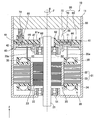
- FIG. 1 is a cross-sectional view showing the motor of the first embodiment.
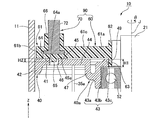
- FIG. 2 is a cross-sectional view showing a part of the motor of the first embodiment.
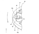
- FIG. 3 is a perspective view showing a part of the bearing holder of the first embodiment.
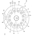
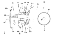
- FIG. 4 is a top view of the bus bar unit and the bearing holder of the first embodiment.
- FIG. 5 is a view of the bus bar unit according to the first embodiment as viewed from below.
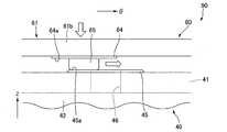
- FIG. 6 is a view of a part of the bus bar unit and a part of the bearing holder of the first embodiment as viewed from the outer side in the radial direction.
- FIG. 7 is a view showing a part of the attachment procedure of the bus bar unit of the first embodiment.
- FIG. 1 is a cross-sectional view showing the motor of the first embodiment.
- FIG. 2 is a cross-sectional view showing a part of the motor of the first embodiment.
- FIG. 3 is a perspective view showing a part of the bearing
- FIG. 8 is a view showing a part of the attachment procedure of the bus bar unit of the first embodiment.
- FIG. 9 is a view of a part of the bus bar unit and a part of the bearing holder of the second embodiment as viewed from the outer side in the radial direction.
- the Z-axis direction appropriately shown in each drawing is a vertical direction with the positive side as the upper side and the negative side as the lower side.
- a central axis J appropriately shown in each drawing is an imaginary line which is parallel to the Z-axis direction and extends in the vertical direction.
- the axial direction of the central axis J that is, the direction parallel to the vertical direction
- the radial direction centering on the central axis J is simply referred to as “radial direction”.
- the circumferential direction centered on is simply referred to as "circumferential direction”.
- the circumferential direction is appropriately indicated by an arrow ⁇ .
- the positive side in the Z-axis direction in the axial direction is called “upper side”
- the negative side in the Z-axis direction in the axial direction is called “lower side”.
- the upper side corresponds to one side in the axial direction
- the lower side corresponds to the other side in the axial direction.
- the side which proceeds in the counterclockwise direction as viewed from the upper side to the lower side in the circumferential direction that is, the side which proceeds in the direction of the arrow ⁇
- the side advancing clockwise as viewed from the upper side to the lower side in the circumferential direction that is, the side advancing in the direction opposite to the direction of the arrow ⁇ is referred to as “the other side in the circumferential direction”.
- the vertical direction, the upper side, and the lower side are simply names for describing the relative positional relationship of each part, and the actual positional relationship may be a positional relationship other than the positional relationship indicated by these names. .
- a motor 10 As shown in FIGS. 1 and 2, a motor 10 according to the present embodiment includes a housing 11, a rotor 20, bearings 51 and 52, a stator 30, a bearing holder 40, and a bus bar unit 90. And a control device 80. As shown in FIG. 1, the housing 11 accommodates each part of the motor 10. The housing 11 is cylindrical around the central axis J. The housing 11 holds the bearing 51 at the bottom on the lower side.
- the rotor 20 has a shaft 21, a rotor core 22, and a magnet 23.
- the shaft 21 is disposed along the central axis J.
- the shaft 21 is rotatably supported by bearings 51 and 52.
- the rotor core 22 has an annular shape fixed to the outer peripheral surface of the shaft 21.
- the magnet 23 is fixed to the outer peripheral surface of the rotor core 22.
- the bearing 51 rotatably supports the shaft 21 on the lower side of the rotor core 22.
- the bearing 52 rotatably supports the shaft 21 on the upper side of the rotor core 22.
- the bearings 51 and 52 are ball bearings.
- the stator 30 faces the rotor 20 in the radial direction via a gap.
- the stator 30 surrounds the rotor 20 at the radially outer side of the rotor 20.
- the stator 30 has a stator core 31, an insulator 34, and a plurality of coils 35.
- the stator core 31 has a core back 32 and a plurality of teeth 33.
- the plurality of coils 35 are respectively attached to the plurality of teeth 33 via the insulators 34.
- the coil 35 is configured by winding a conducting wire around the teeth 33 through the insulator 34. From each coil 35, a coil leader 35a is drawn upward.
- the coil lead-out wire 35 a is a conducting wire extending from the coil 35 and is an end of the conducting wire that constitutes the coil 35.
- the bearing holder 40 is disposed on the upper side of the stator 30.
- the bearing holder 40 is made of metal.
- the bearing holder 40 holds the bearing 52.
- the bearing holder 40 includes a first outer annular portion 41, a fixed cylindrical portion 42, a first inner annular portion 47, a plurality of first connection portions 44, and a bearing holder. It has a portion 43 and a first projecting portion 45.
- the first outer annular portion 41 has an annular plate shape whose center is the central axis J and whose plate surface is orthogonal to the axial direction.
- the fixed cylindrical portion 42 has a cylindrical shape extending downward from the radial outer edge portion of the first outer annular portion 41. As shown in FIG.
- the first inner annular portion 47 is cylindrical with the central axis J as a center.
- the first inner annular portion 47 is disposed radially inward of the first outer annular portion 41.
- the lower end of the first inner annular portion 47 is curved radially inward.
- the plurality of first connection portions 44 extend in the radial direction.
- the plurality of first connection portions 44 are arranged at equal intervals along the circumferential direction. For example, twelve first connection portions 44 are provided.
- the plurality of first connection portions 44 connect the radially inner edge portion of the first outer annular portion 41 and the upper end portion of the first inner annular portion 47.
- a part of the first connection portions 44 of the first connection portions 44 has a circumferential width that is large at a radially outer portion. For example, in the three first connection portions 44, the circumferential width becomes larger at the radially outer portion.
- the three first connection portions 44 are arranged at equal intervals along the circumferential direction.
- First through holes 48 are provided between the first connection portions 44 adjacent to each other in the circumferential direction. The first through hole 48 penetrates the bearing holder 40 in the axial direction. A coil lead-out wire 35 a extending from each coil 35 is passed through each of the first through holes 48.
- the bearing holding portion 43 is connected to the radially inner edge portion of the lower end portion of the first inner annular portion 47.
- the bearing holding portion 43 has a cylindrical portion 43a, a lid portion 43b, and an annular projecting portion 43c.
- the cylindrical portion 43a has a cylindrical shape centered on the central axis J.
- the outer peripheral surface of the bearing 52 is fixed to the inner peripheral surface of the cylindrical portion 43a.
- the bearing holder 43 holds the bearing 52.
- the bearing 52 is spaced apart below the lid 43 b.
- the lid 43 b has an annular shape that protrudes radially inward from the upper end of the cylindrical portion 43 a.
- the lid 43 b covers the upper side of the outer ring of the bearing 52.
- the annular projection 43c protrudes upward from the radial inner edge of the lid 43b.
- the annular projecting portion 43 c has an annular shape centered on the central axis J.
- the inner circumferential surface of the annular projection 43c is connected to the upper end of the inner circumferential surface of the lid 43b.
- the inner circumferential surface of the annular projection 43c and the inner circumferential surface of the lid 43b are disposed at the same position in the radial direction.
- the lid 43 b and the annular projection 43 c constitute a first central hole 49 axially penetrating the bearing holder 40. That is, the bearing holder 40 has a first central hole 49.
- the inner peripheral surface of the first central hole 49 is constituted by the inner peripheral surface of the lid 43 b and the inner peripheral surface of the annular projection 43 c.
- the first central hole 49 has a circular shape centered on the central axis J when viewed along the axial direction.
- the bearing holder main body 40 a is configured by the first outer annular portion 41, the fixed cylindrical portion 42, the first inner annular portion 47, the plurality of first connection portions 44, and the bearing holding portion 43. That is, the bearing holder 40 has a bearing holder main body 40a.
- the first protrusion 45 protrudes upward from the bearing holder main body 40 a.
- the first projecting portion 45 is provided across the first outer annular portion 41 and the first connection portion 44.
- the first projecting portions 45 are respectively provided to the first connection portions 44 in which the width in the circumferential direction described above in the first connection portions 44 is larger in the radially outer portion. That is, in the present embodiment, three first protrusions 45 are provided, and arranged at equal intervals along the circumferential direction.
- the upper surface of the first protrusion 45 is a lower contact surface 45 a.
- the lower contact surface 45a is a flat surface orthogonal to the axial direction.
- the shape viewed from the upper side of the lower contact surface 45a is a substantially square shape of a corner.
- the lower contact surface 45 a is the uppermost portion of the bearing holder 40.
- One of the plurality of first protrusions 45 has a hole 46 that is recessed in the axial direction. That is, the bearing holder 40 has a hole 46.
- the hole 46 is recessed downward from the lower contact surface 45 a. That is, the hole 46 opens in the upper surface of the first protrusion 45.
- the shape viewed from the upper side of the hole 46 is circular.
- the hole 46 is disposed at the center of the first protrusion 45. As shown in FIG. 2, the hole 46 axially penetrates the bearing holder 40 from the lower contact surface 45 a to the lower surface of the first connection portion 44.
- the bus bar unit 90 is disposed on the upper side of the bearing holder 40.
- the bus bar unit 90 has a plurality of bus bars 70 and a bus bar holder 60.
- the bus bar holder 60 is made of resin.
- the bus bar holder 60 includes the bus bar holder main body 61, the upper central cylindrical portion 62, the lower central cylindrical portion 63, the second projecting portion 64, and the fitting convex portion 65, And a terminal support portion 66.
- the bus bar holder main body 61 has a second inner annular portion 61a, a second outer annular portion 61b, and a plurality of second connection portions 61c.
- the second inner annular portion 61 a and the second outer annular portion 61 b are annular around the central axis J.
- the second outer annular portion 61 b surrounds the second inner annular portion 61 a at a radially outer side of the second inner annular portion 61 a as viewed in the axial direction.
- the second inner annular portion 61 a is disposed on the upper side of the bearing holding portion 43.
- the second outer annular portion 61 b is disposed on the upper side of the first outer annular portion 41.
- the second inner annular portion 61 a and the second outer annular portion 61 b are disposed at the same position in the axial direction.
- the outer diameter of the second outer annular portion 61 b is smaller than the outer diameter of the bearing holder 40.
- the plurality of second connection portions 61 c extend in the radial direction.
- the plurality of second connection portions 61c are arranged at equal intervals along the circumferential direction. In FIG. 4, for example, twelve second connection portions 61 c are provided.
- the plurality of second connection portions 61c connect the second outer annular portion 61b and the second inner annular portion 61a. More specifically, the plurality of second connection portions 61c connect the radially inner edge portion of the second outer annular portion 61b and the radially outer edge portion of the second inner annular portion 61a.
- the second connection portion 61 c overlaps with the first connection portion 44 as viewed in the axial direction.
- Second through holes 67 are provided between the second connection portions 61 c adjacent in the circumferential direction.
- the second through holes 67 penetrate the bus bar holder 60 in the axial direction.
- the second through holes 67 overlap the first through holes 48 as viewed in the axial direction.
- a coil leader 35a extending upward through the first through holes 48 is inserted.
- the upper central cylindrical portion 62 has a cylindrical shape that centers on the central axis J and protrudes upward from the radially inner edge portion of the second inner annular portion 61 a.
- the lower central tubular portion 63 has a cylindrical shape with the central axis J as a center and projecting downward from the radially inner edge portion of the second inner annular portion 61a. That is, the lower central tubular portion 63 has a cylindrical shape with the central axis J as a center and projecting downward from the bus bar holder main body 61.
- the inside of the upper central cylindrical portion 62 and the inner of the lower central cylindrical portion 63 are connected in the axial direction, and penetrate the bus bar holder 60 in the axial direction.
- the upper end portion of the shaft 21 is passed through the inside of the upper center cylindrical portion 62 and the inside of the lower center cylindrical portion 63.
- the lower end portion of the lower central tubular portion 63 is a portion located on the lowermost side in the bus bar unit 90. As shown in FIG. 2, the lower central tubular portion 63 is fitted into the first central hole 49. The lower end portion of the lower central tubular portion 63 is disposed on the upper side of the bearing 52 so as to be opposed to each other via a gap. The lower end of the lower central tubular portion 63 is disposed substantially at the same position as the lower end of the first central hole 49 in the axial direction. In the present embodiment, the lower central tubular portion 63 corresponds to a first central tubular portion.
- the second protrusion 64 protrudes downward from the bus bar holder main body 61. As shown in FIG. 5, the second protrusion 64 is provided across the second outer annular portion 61 b and the second connection portion 61 c. A plurality of second protrusions 64 are provided. The plurality of second protrusions 64 are arranged at equal intervals along the circumferential direction. In FIG. 5, for example, three second protrusions 64 are provided. As shown in FIG. 6, the first protrusion 45 and the second protrusion 64 overlap with each other as viewed in the axial direction.
- the lower surface of the second protrusion 64 is an upper contact surface 64 a.
- the upper contact surface 64a is a flat surface orthogonal to the axial direction. As shown in FIG. 2, the upper contact surface 64 a is disposed above the lower end of the lower central tubular portion 63. As shown in FIG. 5, the shape viewed from the lower side of the upper contact surface 64a is a rectangular shape elongated in the radial direction. As shown in FIG. 6, the lower contact surfaces 45 a of the first protrusions 45 and the upper contact surfaces 64 a of the second protrusions 64 contact each other. Thereby, the bus bar unit 90 is positioned in the axial direction with respect to the bearing holder 40.
- the lower contact surface 45 a and the upper contact surface 64 a are flat surfaces orthogonal to the axial direction, it is possible to suppress the bus bar unit 90 from being inclined to the bearing holder 40. Further, the bus bar unit 90 can be stably supported by the bearing holder 40.
- the fitting protrusion 65 is provided on one second protrusion 64 of the plurality of second protrusions 64.
- the fitting convex portion 65 is a column that protrudes downward from the upper contact surface 64 a.
- the shape viewed from the lower side of the fitting convex portion 65 is a rounded rectangular shape that is long in the direction orthogonal to both the radial direction and the axial direction.
- the lower surface of the fitting protrusion 65 is a flat surface orthogonal to the axial direction.
- the fitting protrusion 65 is fitted in the hole 46.
- the longitudinal dimension of the fitting projection 65 in the direction orthogonal to the axial direction is substantially the same as the inner diameter of the hole 46 and slightly smaller than the inner diameter of the hole 46.
- the longitudinal direction of the fitting convex portion 65 is the left-right direction in FIG.
- the lower end of the fitting projection 65 is disposed above the lower end of the hole 46. As shown in FIG. 2, the lower end of the fitting protrusion 65 is disposed above the lower end of the lower central tubular portion 63.
- the axial dimension H2 of the portion of the fitting convex portion 65 fitted in the hole 46 is smaller than the axial dimension H1 of the portion of the lower central tubular portion 63 fitted in the first central hole 49.
- the dimension H 1 corresponds to the axial distance between the upper end of the first central hole 49 and the lower end of the lower central tubular portion 63.
- the dimension H 2 corresponds to the axial distance between the upper end of the hole 46 and the lower end of the fitting projection 65.
- the fitting projection 65 is entirely fitted in the hole 46. Therefore, the dimension H2 corresponds to the dimension of the fitting convex portion 65 in the axial direction.
- the terminal support portion 66 protrudes upward from the bus bar holder main body 61. More specifically, the terminal support portion 66 protrudes upward from the second outer annular portion 61 b.
- the terminal support 66 is in the form of a rectangular parallelepiped. As shown in FIG. 4, a plurality of terminal support portions 66 are provided. The plurality of terminal support portions 66 are arranged at equal intervals along the circumferential direction. In FIG. 4, for example, three terminal support portions 66 are provided. Each of the three terminal support portions 66 is disposed at a position overlapping with each of the three second protrusions 64 as viewed in the axial direction.
- each of the plurality of bus bars 70 has a bus bar main body 71, a connection terminal 72, and a grip portion 73.
- three bus bars 70 are provided.
- Each of the three bus bars 70 is provided with one connection terminal 72 and four grips 73 respectively. That is, in the present embodiment, a total of three connection terminals 72 are provided, and a total of twelve gripping portions 73 are provided.
- the bus bar main body 71 is embedded in the bus bar holder 60.
- the bus bar holder 60 holds the bus bar 70.
- the bus bar main body 71 has a plate shape whose plate surface is orthogonal to the axial direction.
- the bus bar main body 71 extends along a plane orthogonal to the axial direction.
- the connection terminal 72 is connected to the bus bar main body 71.
- the connection terminal 72 protrudes upward from the bus bar holder 60. More specifically, the connection terminal 72 protrudes upward from the terminal support 66.
- the lower portion of the connection terminal 72 is supported by the terminal support 66.
- the upper end of the connection terminal 72 is connected to the controller 80.
- the connection terminals 72 of the three bus bars 70 are arranged at equal intervals along the circumferential direction.
- the gripping portion 73 has a plate shape whose plate surface is orthogonal to the axial direction.
- the gripping portion 73 is connected to the bus bar main body 71, protrudes from the second connection portion 61c in the circumferential direction to one side, and is exposed to the outside of the bus bar holder 60.
- the gripping portion 73 is disposed in the second through hole 67.
- the gripping portion 73 is substantially U-shaped and opens in one circumferential side.
- the gripping portion 73 has a base portion 73a and a pair of arm portions 73b and 73c.
- the base portion 73a is a portion connected to the bus bar main body 71, and protrudes in the circumferential direction one side from the second connection portion 61c.
- the pair of arm portions 73b and 73c extend from the base portion 73a in the circumferential direction to one side.
- the arm portion 73b and the arm portion 73c face each other in the radial direction via a gap.
- the arms 73 b are wavelike when viewed in the axial direction.
- the upper end of the coil lead-out wire 35a is inserted into the inside of the grip 73, that is, between the arm 73b and the arm 73c in the radial direction.
- the tip end portions of the pair of arm portions 73b and 73c are crimped from both sides in the radial direction to hold the coil leader 35a from both sides in the radial direction. Thereby, the holding part 73 holds the coil leader 35a.
- the gripping portion 73 and the coil leader 35a are fixed to each other, for example, by welding. Thus, the gripping portion 73 is connected to the coil lead wire 35 a, and the bus bar 70 is electrically connected to the coil 35.
- each of the gripping portions 73 of the plurality of bus bars 70 a pair of arm portions 73b and 73c extend from the base portion 73a in the same circumferential direction. Thereby, each of the holding parts 73 opens on the same side in the circumferential direction.
- the gripping portion 73 is shown open to one side in the circumferential direction. However, as described above, the end of the arm 73b and the end of the arm 73c are caulked by caulking the arms 73b and 73c. The parts may be in contact. In this case, the opening of the gripping portion 73 is in a closed state.
- control device 80 is disposed on the upper side of bus bar unit 90.
- Control device 80 is electrically connected to bus bar 70 via connection terminal 72.
- Controller 80 supplies power to coil 35 via bus bar 70.
- Control device 80 has a substrate or the like provided with an inverter circuit that controls the power supplied to coil 35.
- the worker attaching the bus bar unit 90 to the bearing holder 40 is, as shown in FIG. 7, the bus bar unit 90 relative to the bearing holder 40 in the circumferential direction opposite to the side where the grip portion 73 opens, ie, the other circumferential direction Position roughly at a position slightly offset to the side. Then, as shown in FIG. 8, the worker brings the bus bar unit 90 close to the bearing holder 40 from the upper side, and brings the lower surface of the fitting convex portion 65 into contact with the lower contact surface 45 a. At this time, the coil lead-out wire 35a extending upward through the first through hole 48 is inserted into the second through hole 67, and faces the gripping portion 73 in the circumferential direction.
- the axial dimension H1 of the portion fitted into the first central hole 49 in the lower central tubular portion 63 is greater than the axial dimension H2 of the portion fitted into the hole 46 in the fitting projection 65. large. Therefore, when the lower surface of the fitting projection 65 comes into contact with the lower contact surface 45a in which the hole 46 opens, the lower end of the lower central tubular portion 63 is fitted into the first central hole 49. It will be As a result, the bus bar unit 90 is rotatably supported around the central axis J with respect to the bearing holder 40 by the engagement of the lower central cylindrical portion 63 and the first central hole 49.
- the worker rotates the bus bar unit 90 in the circumferential direction while applying a downward force to the bus bar unit 90. More specifically, as shown in FIG. 7, the worker rotates the bus bar unit 90 in the circumferential direction toward the opening side of the grip portion 73, that is, in the circumferential direction. Thereby, as shown in FIG. 8, the lower surface of the fitting convex portion 65 moves in the circumferential direction while sliding on the lower contact surface 45a. Then, when the fitting projection 65 moves to a position where the fitting projection 65 axially overlaps the hole 46, the fitting projection 65 fits in the hole 46, and the upper contact surface 64a of the bus bar unit 90 is in the lower contact surface 45a. Move downward until it makes contact.
- the operator can position and attach the bus bar unit 90 with respect to the bearing holder 40 in the axial direction and the circumferential direction. Since the bus bar unit 90 can be positioned in the circumferential direction with respect to the bearing holder 40, the connection terminals 72 can be positioned in the circumferential direction. Thus, the connection terminal 72 can be easily connected to the control device 80. Further, in the state where bus bar unit 90 is positioned in the circumferential direction with respect to bearing holder 40, coil lead-out wire 35a is inserted into the inside of grip 73 through the opening of grip 73. Thereby, the position of the coil lead-out wire 35a can be matched with the position which can be connected with the bus bar 70.
- the bus bar unit 90 can be rotated with the lower center cylindrical portion 63 as a rotation axis.
- the operator rotates the bus bar unit 90 from the state where the coil lead wire 35a is positioned at a position shifted in the circumferential direction with respect to the gripping portion 73, to a position where the fitting convex portion 65 is fitted into the hole 46.
- the coil leader 35a can be inserted into the inside of the grip portion 73.
- each gripping portion 73 is on the same side in the circumferential direction before the coil leader 35a is fixed. Open to Thus, by rotating the bus bar unit 90 in one direction, each of the plurality of coil lead wires 35 a can be inserted inside the plurality of gripping portions 73.
- the coil lead-out wire 35 a is a portion of the second through hole 67 in the circumferential direction one side of the gripping portion 73, that is, the gripping portion 73 of the second through hole 67. It may be inserted into a relatively wider portion than the inside of the. Therefore, as compared with the case where the bus bar unit 90 is positioned at a position where the coil leader 35 a is directly inserted into the inside of the grip portion 73, positional deviation of the bus bar unit 90 in the circumferential direction is allowed. Thereby, the positioning of the bus bar unit 90 when bringing the bus bar unit 90 close to the bearing holder 40 can be facilitated. In addition, even when the coil leader 35a is displaced, the coil leader 35a can be easily inserted at a desired position, that is, a position of the second through hole 67 that is offset in the circumferential direction with respect to the grip portion 73.
- the bus bar unit 90 can be positioned in the circumferential direction. Therefore, according to the present embodiment, the coil lead-out wire 35a can be easily inserted into the grip portion 73, and the coil lead-out wire 35a can be easily connected to the bus bar 70.
- the inner portion of the grip 73 is smaller. Therefore, as the motor 10 is miniaturized, it is more difficult to bring the bus bar unit 90 close to the bearing holder 40 and directly insert the coil lead-out wire 35a into the grip portion 73. Therefore, the effect that the coil leader 35a can be easily inserted into the grip 73 described above is particularly useful in a relatively small motor.
- the hole 46 is provided in the bearing holder 40, and the fitting protrusion 65 is provided in the bus bar holder 60. Therefore, the strength of the bus bar holder 60 can be easily secured as compared to the case where the holes are provided in the bus bar holder 60.
- the upper surface of the first projecting portion 45 is the lower contact surface 45a which is a flat surface, and the hole 46 opens in the lower contact surface 45a. Therefore, the fitting projection 65 can be fitted to the hole 46 by pressing the fitting projection 65 against the lower contact surface 45 a and sliding it.
- the fitting convex portion 65 can be easily fitted to the hole 46.
- the friction between the fitting convex portion 65 and the bearing holder 40 can be easily reduced, and the bus bar unit 90 can be easily rotated in the circumferential direction. Moreover, it can suppress that the fitting convex part 65 is damaged.
- the lower surface of the fitting convex portion 65 is a flat surface orthogonal to the axial direction. Therefore, when the fitting convex portion 65 is pressed to the lower contact surface 45 a, the fitting convex portion 65 and the lower contact surface 45 a can be stably brought into contact with each other. Thus, the bus bar unit 90 can be stably rotated with respect to the bearing holder 40.
- the lower end portion of the lower central tubular portion 63 is disposed lower than the fitting convex portion 65. Therefore, the axial dimension of the lower central tubular portion 63 can be easily increased, and the axial dimension H1 of the portion fitted in the lower central tubular portion 63 can be easily enlarged. Therefore, by fitting the lower central tubular portion 63 and the first central hole 49, the bus bar unit 90 can be stably and rotatably supported.
- the annular projecting portion 43 c which constitutes a part of the inner peripheral surface of the first central hole 49 is provided. Therefore, the axial dimension of the first central hole 49 can be easily increased. As a result, the axial dimension H1 of the portion to be fitted in the lower central tubular portion 63 can be easily increased.
- the bearing 52 is disposed below the lid 43 b and away from the lid 43 b. Therefore, the bearing 52 can be easily separated downward from the lower central tubular portion 63 fitted in the first central hole 49. Therefore, even if the axial dimension of the lower central tubular portion 63 is increased as described above, the lower end of the lower central tubular portion 63 can be prevented from contacting the bearing 52.
- the bearing holder 140 has a fitting protrusion 146.
- the fitting protrusion 146 protrudes upward from the first protrusion 145.
- the bus bar holder 160 has a hole 165.
- the hole 165 opens in the lower surface of the second protrusion 164.
- the hole 165 is recessed upward from the lower surface of the second protrusion 164.
- the hole 165 penetrates the bus bar holder 160 in the axial direction.
- the fitting protrusion 146 is fitted in the hole 165.
- the hole 165 is provided in the bus bar holder 160, and the fitting protrusion 146 is provided in the bearing holder 140. Therefore, the strength of the bearing holder 140 can be easily secured as compared to the case where the hole is provided in the bearing holder 140.
- the bus bar holder 60 includes the lower central tubular portion 63 as the first central tubular portion, and the bearing holder 40 includes the first central hole 49, but the present invention is not limited thereto.
- the bus bar holder has a second central hole which passes through the bus bar holder in the axial direction with the central axis J as the center, and the bearing holder has a cylindrical shape with the central axis J as the center and projecting upward from the bearing holder body.
- the second central tubular portion may be provided.
- the bus bar unit is rotatably supported with respect to the bearing holder by the second central tubular portion being fitted to the second central hole.
- the axial dimension of the portion fitted in the second central hole in the second central tubular portion is larger than the axial dimension of the portion fitted in the hole in the fitting projection.
- the hole may be a hole having a bottom.
- a plurality of holes may be provided.
- the fitting convex portion may be provided for each hole or may be provided only for a part of the holes.
- the number of first protrusions and the number of second protrusions are not particularly limited.
- the first and second protrusions may not be provided.
- the number of connection terminals is not particularly limited.
- the number of bus bars and the number of grips are not particularly limited as long as they are two or more.
- the bearing may contact a lid of the bearing holder.
- the bearing holder may not have an annular protrusion.
Landscapes
- Engineering & Computer Science (AREA)
- Power Engineering (AREA)
- Insulation, Fastening Of Motor, Generator Windings (AREA)
- Motor Or Generator Frames (AREA)
Abstract
本発明のモータの一つの態様において、複数のバスバーのそれぞれは、コイルから延びる導線を把持する把持部を有する。把持部のそれぞれにおいては、一対の腕部が基部から周方向の同じ側に延びる。バスバーホルダは、バスバーホルダ本体と、中心軸を中心としバスバーホルダ本体から軸方向他方側に突出する円筒状の第1中央筒部と、を有する。ベアリングホルダは、中心軸を中心としベアリングホルダを軸方向に貫通する第1中央孔部を有する。第1中央筒部は、第1中央孔部に嵌め合わされる。ベアリングホルダとバスバーホルダとのうちの一方は、軸方向に窪む穴部を有する。ベアリングホルダとバスバーホルダとのうちの他方は、軸方向に突出する嵌合凸部を有する。嵌合凸部は、穴部に嵌め合わされる。第1中央筒部における第1中央孔部に嵌め合わされた部分の軸方向の寸法は、嵌合凸部における穴部に嵌め合わされた部分の軸方向の寸法よりも大きい。
Description
本発明は、モータに関する。
バスバーを保持するバスバーホルダが、ベアリングを保持するベアリングホルダに対して取り付けられるモータが知られる。例えば、特許文献1には、ベアリングホルダとしての絶縁プレートとバスバーホルダとがねじで固定されたモータが記載される。
上記のようなモータにおいては、コイルから延びる導線がベアリングホルダを貫通し、バスバーに接続される。そのため、作業者は、ベアリングホルダに対してバスバーホルダの周方向位置を合わせてからバスバーホルダをベアリングホルダに取り付けた後に、バスバーと導線とを接続する。しかし、このようにバスバーホルダをベアリングホルダに取り付ける場合、コイルから延びる導線の位置がずれる等により、バスバーに対する導線の位置を所望の位置に配置しにくい場合があった。そのため、導線をバスバーに接続しにくい課題があった。
本発明は、上記事情に鑑みて、コイルから延びる導線をバスバーに接続しやすくできる構造を有するモータを提供することを目的の一つとする。
本発明の第1の観点に係るモータは、中心軸に沿って配置されたシャフトを有するロータと、コイルを有し、前記ロータと径方向に隙間を介して対向するステータと、前記シャフトを回転可能に支持するベアリングと、前記ステータよりも軸方向一方側に配置され、前記ベアリングを保持するベアリングホルダと、前記ベアリングホルダよりも軸方向一方側に配置されるバスバーユニットと、を備えるモータである。前記バスバーユニットは、記コイルと電気的に接続される複数のバスバーと、前記バスバーを保持し、前記ベアリングホルダよりも軸方向一方側に配置されるバスバーホルダと、を有し、前記複数のバスバーのそれぞれは、前記コイルから延びる導線を把持する把持部を有し、前記把持部は、基部と、前記基部から周方向一方側に延び、径方向に隙間を介して対向する一対の腕部と、を有し、前記一対の腕部における径方向の間には、前記コイルから延びる導線が挿入され、前記複数のバスバーにおける前記把持部のそれぞれにおいては、前記一対の腕部が前記基部から周方向の同じ側に延び、前記バスバーホルダは、バスバーホルダ本体と、前記中心軸を中心とし前記バスバーホルダ本体から軸方向他方側に突出する円筒状の第1中央筒部と、を有し、前記ベアリングホルダは、前記中心軸を中心とし前記ベアリングホルダを軸方向に貫通する第1中央孔部を有し、前記第1中央筒部は、前記第1中央孔部に嵌め合わされ、前記ベアリングホルダと前記バスバーホルダとのうちの一方は、軸方向に窪む穴部を有し、前記ベアリングホルダと前記バスバーホルダとのうちの他方は、軸方向に突出する嵌合凸部を有し、前記嵌合凸部は、前記穴部に嵌め合わされ、前記第1中央筒部における前記第1中央孔部に嵌め合わされた部分の軸方向の寸法は、前記嵌合凸部における前記穴部に嵌め合わされた部分の軸方向の寸法よりも大きい、モータ。
本発明の第2の観点に係るモータは、中心軸に沿って配置されたシャフトを有するロータと、コイルを有し、前記ロータと径方向に隙間を介して対向するステータと、前記シャフトを回転可能に支持するベアリングと、前記ステータよりも軸方向一方側に配置され、前記ベアリングを保持するベアリングホルダと、前記ベアリングホルダよりも軸方向一方側に配置されるバスバーユニットと、を備えるモータである。前記バスバーユニットは、前記コイルと電気的に接続される複数のバスバーと、前記バスバーを保持し、前記ベアリングホルダよりも軸方向一方側に配置されるバスバーホルダと、を有し、前記複数のバスバーのそれぞれは、前記コイルから延びる導線を把持する把持部を有し、前記把持部は、基部と、前記基部から周方向一方側に延び、径方向に隙間を介して対向する一対の腕部と、を有し、前記一対の腕部における径方向の間には、前記コイルから延びる導線が挿入され、前記複数のバスバーにおける前記把持部のそれぞれにおいては、前記一対の腕部が前記基部から周方向の同じ側に延び、前記ベアリングホルダは、ベアリングホルダ本体と、前記中心軸を中心とし前記ベアリングホルダ本体から軸方向一方側に突出する円筒状の第2中央筒部と、を有し、前記バスバーホルダは、前記中心軸を中心とし前記バスバーホルダを軸方向に貫通する第2中央孔部を有し、前記第2中央筒部は、前記第2中央孔部に嵌め合わされ、前記ベアリングホルダと前記バスバーホルダとのうちの一方は、軸方向に窪む穴部を有し、前記ベアリングホルダと前記バスバーホルダとのうちの他方は、軸方向に突出する嵌合凸部を有し、前記嵌合凸部は、前記穴部に嵌め合わされ、前記第2中央筒部における前記第2中央孔部に嵌め合わされた部分の軸方向の寸法は、前記嵌合凸部における前記穴部に嵌め合わされた部分の軸方向の寸法よりも大きい、モータ。
本発明の一つの態様によれば、コイルから延びる導線をバスバーに接続しやすくできる構造を有するモータが提供される。
各図に適宜示すZ軸方向は、正の側を上側とし、負の側を下側とする上下方向である。各図に適宜示す中心軸Jは、Z軸方向と平行であり、上下方向に延びる仮想線である。以下の説明においては、中心軸Jの軸方向、すなわち上下方向と平行な方向を単に「軸方向」と呼び、中心軸Jを中心とする径方向を単に「径方向」と呼び、中心軸Jを中心とする周方向を単に「周方向」と呼ぶ。各図においては、適宜、周方向を矢印θで示す。
また、軸方向におけるZ軸方向の正の側を「上側」と呼び、軸方向におけるZ軸方向の負の側を「下側」と呼ぶ。本実施形態において、上側は、軸方向一方側に相当し、下側は、軸方向他方側に相当する。また、周方向における上側から下側に向かって視て反時計回りに進む側、すなわち矢印θの向きに進む側を「周方向一方側」と呼ぶ。周方向における上側から下側に向かって視て時計回りに進む側、すなわち矢印θの向きと逆に進む側を「周方向他方側」と呼ぶ。
なお、上下方向、上側および下側とは、単に各部の相対位置関係を説明するための名称であり、実際の配置関係は、これらの名称で示される配置関係以外の配置関係であってもよい。
<第1実施形態>図1および図2に示すように、本実施形態のモータ10は、ハウジング11と、ロータ20と、ベアリング51,52と、ステータ30と、ベアリングホルダ40と、バスバーユニット90と、制御装置80と、を備える。図1に示すように、ハウジング11は、モータ10の各部を収容する。ハウジング11は、中心軸Jを中心とする円筒状である。ハウジング11は、下側の底部にベアリング51を保持する。
ロータ20は、シャフト21と、ロータコア22と、マグネット23と、を有する。シャフト21は、中心軸Jに沿って配置される。シャフト21は、ベアリング51,52によって回転可能に支持される。ロータコア22は、シャフト21の外周面に固定される円環状である。マグネット23は、ロータコア22の外周面に固定される。ベアリング51は、ロータコア22の下側においてシャフト21を回転可能に支持する。ベアリング52は、ロータコア22の上側においてシャフト21を回転可能に支持する。ベアリング51,52は、ボールベアリングである。
ステータ30は、ロータ20と径方向に隙間を介して対向する。ステータ30は、ロータ20の径方向外側においてロータ20を囲む。ステータ30は、ステータコア31と、インシュレータ34と、複数のコイル35と、を有する。ステータコア31は、コアバック32と、複数のティース33と、を有する。
複数のコイル35は、インシュレータ34を介して複数のティース33にそれぞれ装着される。コイル35は、導線がインシュレータ34を介してティース33に巻き回されて構成される。各コイル35からはコイル引出線35aが上側に引き出される。コイル引出線35aは、コイル35から延びる導線であり、コイル35を構成する導線の端部である。
ベアリングホルダ40は、ステータ30の上側に配置される。ベアリングホルダ40は、金属製である。ベアリングホルダ40は、ベアリング52を保持する。図2および図3に示すように、ベアリングホルダ40は、第1外側円環部41と、固定筒部42と、第1内側円環部47と、複数の第1接続部44と、ベアリング保持部43と、第1突出部45と、を有する。第1外側円環部41は、中心軸Jを中心とし、板面が軸方向と直交する円環板状である。固定筒部42は、第1外側円環部41の径方向外縁部から下側に延びる円筒状である。図1に示すように、第1外側円環部41の外周面および固定筒部42の外周面は、ハウジング11の内周面に固定される。第1内側円環部47は、中心軸Jを中心とする円筒状である。第1内側円環部47は、第1外側円環部41よりも径方向内側に配置される。第1内側円環部47の下側の端部は、径方向内側に湾曲する。
図2および図3に示すように、複数の第1接続部44は、径方向に延びる。複数の第1接続部44は、周方向に沿って一周に亘って等間隔に配置される。第1接続部44は、例えば、12個設けられる。複数の第1接続部44は、第1外側円環部41の径方向内縁部と第1内側円環部47の上側の端部とを繋ぐ。
第1接続部44のうち一部の第1接続部44は、周方向の幅が径方向外側の部分において大きくなる。例えば、3つの第1接続部44が、周方向の幅が径方向外側の部分において大きくなる。この3つの第1接続部44は、周方向に沿って一周に亘って等間隔に配置される。周方向に隣り合う第1接続部44同士の間には、それぞれ第1貫通孔48が設けられる。第1貫通孔48は、ベアリングホルダ40を軸方向に貫通する。第1貫通孔48のそれぞれには、各コイル35から延びるコイル引出線35aが通される。
図2に示すように、ベアリング保持部43は、第1内側円環部47の下端部の径方向内縁部に繋がる。ベアリング保持部43は、筒部43aと、蓋部43bと、円環突出部43cと、を有する。筒部43aは、中心軸Jを中心とする円筒状である。筒部43aの内周面には、ベアリング52の外周面が固定される。これにより、ベアリング保持部43は、ベアリング52を保持する。ベアリング52は、蓋部43bよりも下側に離れて配置される。
蓋部43bは、筒部43aの上側の端部から径方向内側に突出する円環状である。蓋部43bは、ベアリング52の外輪の上側を覆う。円環突出部43cは、蓋部43bの径方向内縁部から上側に突出する。円環突出部43cは、中心軸Jを中心とする円環状である。円環突出部43cの内周面は、蓋部43bの内周面の上端部に繋がる。円環突出部43cの内周面と蓋部43bの内周面とは、径方向において同じ位置に配置される。
本実施形態では、蓋部43bと円環突出部43cとによって、ベアリングホルダ40を軸方向に貫通する第1中央孔部49が構成される。すなわち、ベアリングホルダ40は、第1中央孔部49を有する。第1中央孔部49の内周面は、蓋部43bの内周面と円環突出部43cの内周面とによって構成される。第1中央孔部49は、軸方向に沿って視て、中心軸Jを中心とする円形状である。
本実施形態では、第1外側円環部41と固定筒部42と第1内側円環部47と複数の第1接続部44とベアリング保持部43とによって、ベアリングホルダ本体40aが構成される。すなわち、ベアリングホルダ40は、ベアリングホルダ本体40aを有する。
図2および図3に示すように、第1突出部45は、ベアリングホルダ本体40aから上側に突出する。第1突出部45は、第1外側円環部41と第1接続部44とに跨って設けられる。第1突出部45は、第1接続部44のうち、上述した周方向の幅が径方向外側の部分において大きくなる第1接続部44にそれぞれ設けられる。すなわち、本実施形態において第1突出部45は、3つ設けられ、周方向に沿って一周に亘って等間隔に配置される。
第1突出部45の上側の面は、下側接触面45aである。下側接触面45aは、軸方向と直交する平坦な面である。下側接触面45aの上側から視た形状は、角丸の略正方形状である。下側接触面45aは、ベアリングホルダ40のうちで最も上側に位置する部分である。
複数の第1突出部45のうちの1つの第1突出部45は、軸方向に窪む穴部46を有する。すなわち、ベアリングホルダ40は、穴部46を有する。穴部46は、下側接触面45aから下側に窪む。すなわち、穴部46は、第1突出部45の上側の面に開口する。穴部46の上側から視た形状は、円形状である。穴部46は、第1突出部45の中央に配置される。図2に示すように、穴部46は、下側接触面45aから第1接続部44の下面まで、ベアリングホルダ40を軸方向に貫通する。
図1に示すように、バスバーユニット90は、ベアリングホルダ40の上側に配置される。バスバーユニット90は、複数のバスバー70と、バスバーホルダ60と、を有する。バスバーホルダ60は、樹脂製である。図4および図5に示すように、バスバーホルダ60は、バスバーホルダ本体61と、上側中央筒部62と、下側中央筒部63と、第2突出部64と、嵌合凸部65と、端子支持部66と、を有する。
バスバーホルダ本体61は、第2内側円環部61aと、第2外側円環部61bと、複数の第2接続部61cと、を有する。第2内側円環部61aおよび第2外側円環部61bは、中心軸Jを中心とする円環状である。第2外側円環部61bは、軸方向に沿って視て、第2内側円環部61aよりも径方向外側において第2内側円環部61aを囲む。図2に示すように、第2内側円環部61aは、ベアリング保持部43の上側に配置される。第2外側円環部61bは、第1外側円環部41の上側に配置される。本実施形態において第2内側円環部61aと第2外側円環部61bとは、軸方向において同じ位置に配置される。第2外側円環部61bの外径は、ベアリングホルダ40の外径よりも小さい。
図4に示すように、複数の第2接続部61cは、径方向に延びる。複数の第2接続部61cは、周方向に沿って一周に亘って等間隔に配置される。図4では、第2接続部61cは、例えば、12個設けられる。複数の第2接続部61cは、第2外側円環部61bと第2内側円環部61aとを繋ぐ。より詳細には、複数の第2接続部61cは、第2外側円環部61bの径方向内縁部と第2内側円環部61aの径方向外縁部とを繋ぐ。第2接続部61cは、軸方向に沿って視て、第1接続部44と重なる。周方向に隣り合う第2接続部61c同士の間には、それぞれ第2貫通孔67が設けられる。第2貫通孔67は、バスバーホルダ60を軸方向に貫通する。第2貫通孔67は、軸方向に沿って視て、第1貫通孔48と重なる。第2貫通孔67のそれぞれには、第1貫通孔48を通って上側に延びるコイル引出線35aが挿入される。
図1に示すように、上側中央筒部62は、中心軸Jを中心とし第2内側円環部61aの径方向内縁部から上側に突出する円筒状である。下側中央筒部63は、中心軸Jを中心とし第2内側円環部61aの径方向内縁部から下側に突出する円筒状である。すなわち、下側中央筒部63は、中心軸Jを中心としバスバーホルダ本体61から下側に突出する円筒状である。
上側中央筒部62の内部と下側中央筒部63の内部とは、軸方向に繋がり、バスバーホルダ60を軸方向に貫通する。上側中央筒部62の内部および下側中央筒部63の内部には、シャフト21の上側の端部が通される。
下側中央筒部63の下側の端部は、バスバーユニット90において最も下側に位置する部分である。図2に示すように、下側中央筒部63は、第1中央孔部49に嵌め合わされる。下側中央筒部63の下側の端部は、ベアリング52の上側に隙間を介して対向して配置される。下側中央筒部63の下側の端部は、軸方向において、第1中央孔部49の下側の端部とほぼ同じ位置に配置される。本実施形態において下側中央筒部63は、第1中央筒部に相当する。
第2突出部64は、バスバーホルダ本体61から下側に突出する。図5に示すように、第2突出部64は、第2外側円環部61bと第2接続部61cとに跨って設けられる。第2突出部64は、複数設けられる。複数の第2突出部64は、周方向に沿って一周に亘って等間隔に配置される。図5では、第2突出部64は、例えば、3つ設けられる。図6に示すように、第1突出部45と第2突出部64とは、軸方向に沿って視て、互いに重なる。
第2突出部64の下側の面は、上側接触面64aである。上側接触面64aは、軸方向と直交する平坦な面である。図2に示すように、上側接触面64aは、下側中央筒部63の下側の端部よりも上側に配置される。図5に示すように、上側接触面64aの下側から視た形状は、径方向に長い長方形状である。図6に示すように、各第1突出部45の下側接触面45aと各第2突出部64の上側接触面64aとは、それぞれ互いに接触する。これにより、ベアリングホルダ40に対してバスバーユニット90が軸方向に位置決めされる。
本実施形態では、下側接触面45aおよび上側接触面64aは軸方向と直交する平坦な面であるため、ベアリングホルダ40に対してバスバーユニット90が傾いて配置されることを抑制できる。また、バスバーユニット90をベアリングホルダ40によって安定して支持することができる。
嵌合凸部65は、複数の第2突出部64のうちの1つの第2突出部64に設けられる。嵌合凸部65は、上側接触面64aから下側に突出する柱状である。図5に示すように、嵌合凸部65の下側から視た形状は、径方向および軸方向の両方と直交する方向に長い角丸長方形状である。嵌合凸部65の下側の面は、軸方向と直交する平坦な面である。図6に示すように、嵌合凸部65は、穴部46に嵌め合わされる。これにより、バスバーユニット90がベアリングホルダ40に対して周方向に位置決めされ、バスバーユニット90とベアリングホルダ40との周方向の相対位置がずれることを抑制できる。
軸方向と直交する方向における嵌合凸部65の寸法のうち長手方向の寸法は、穴部46の内径とほぼ同じであり、穴部46の内径よりも僅かに小さい。嵌合凸部65の長手方向とは、図6における左右方向である。
嵌合凸部65の下側の端部は、穴部46の下側の端部よりも上側に配置される。図2に示すように、嵌合凸部65の下側の端部は、下側中央筒部63の下側の端部よりも上側に配置される。嵌合凸部65における穴部46に嵌め合わされた部分の軸方向の寸法H2は、下側中央筒部63における第1中央孔部49に嵌め合わされた部分の軸方向の寸法H1よりも小さい。寸法H1は、第1中央孔部49の上側の端部と下側中央筒部63の下側の端部との間の軸方向の距離に相当する。寸法H2は、穴部46の上側の端部と、嵌合凸部65の下側の端部との間の軸方向の距離に相当する。本実施形態において嵌合凸部65は、全体が穴部46に嵌め合わされる。そのため、寸法H2は、嵌合凸部65の軸方向の寸法に相当する。
端子支持部66は、バスバーホルダ本体61から上側に突出する。より詳細には、端子支持部66は、第2外側円環部61bから上側に突出する。端子支持部66は、直方体状である。図4に示すように、端子支持部66は、複数設けられる。複数の端子支持部66は、周方向に沿って一周に亘って等間隔に配置される。図4では、端子支持部66は、例えば、3つ設けられる。3つの端子支持部66のそれぞれは、軸方向に沿って視て、3つの第2突出部64のそれぞれと重なる位置に配置される。
図1および図4に示すように、複数のバスバー70のそれぞれは、バスバー本体71と、接続端子72と、把持部73と、を有する。本実施形態においてバスバー70は、例えば、3つ設けられる。3つのバスバー70のそれぞれには、1つの接続端子72と、4つの把持部73と、がそれぞれ設けられる。すなわち、本実施形態において接続端子72は合計3つ設けられ、把持部73は合計12個設けられる。
図1に示すように、バスバー本体71は、バスバーホルダ60に埋め込まれる。これにより、バスバーホルダ60は、バスバー70を保持する。バスバー本体71は、板面が軸方向と直交する板状である。バスバー本体71は、軸方向と直交する平面に沿って延びる。接続端子72は、バスバー本体71と繋がる。接続端子72は、バスバーホルダ60から上側に突出する。より詳細には、接続端子72は、端子支持部66から上側に突出する。接続端子72の下側の部分は、端子支持部66によって支持される。接続端子72の上側の端部は、制御装置80に接続される。図4に示すように、3つのバスバー70の各接続端子72は、周方向に沿って一周に亘って等間隔に配置される。
把持部73は、板面が軸方向と直交する板状である。把持部73は、バスバー本体71と繋がり、第2接続部61cから周方向一方側に突出して、バスバーホルダ60の外部に露出する。把持部73は、第2貫通孔67内に配置される。把持部73は、周方向一方側に開口する略U字状である。把持部73は、基部73aと、一対の腕部73b,73cと、を有する。
基部73aは、バスバー本体71と繋がる部分であり、第2接続部61cから周方向一方側に突出する。一対の腕部73b,73cは、基部73aから周方向一方側に延びる。腕部73bと腕部73cとは、径方向に隙間を介して対向する。腕部73bは、軸方向に沿って視て、波状である。把持部73の内側、すなわち腕部73bと腕部73cとの径方向の間には、コイル引出線35aの上側の端部が挿入される。
図示は省略するが、把持部73は、一対の腕部73b,73cの先端部が径方向両側からカシメられてコイル引出線35aを径方向両側から挟持する。これにより、把持部73は、コイル引出線35aを把持する。把持部73とコイル引出線35aとは、例えば、溶接により互いに固定される。これにより、把持部73は、コイル引出線35aと接続され、バスバー70は、コイル35と電気的に接続される。
複数のバスバー70における把持部73のそれぞれにおいては、一対の腕部73b,73cが基部73aから周方向の同じ側に延びる。これにより、把持部73のそれぞれは、周方向の同じ側に開口する。
なお、各図においては、把持部73が周方向一方側に開口した状態を示すが、上述したように腕部73b,73cがカシメられることで、腕部73bの先端部と腕部73cの先端部とが接触してもよい。この場合、把持部73の開口は、閉塞された状態となる。
図1に示すように、制御装置80は、バスバーユニット90の上側に配置される。制御装置80は、接続端子72を介して、バスバー70と電気的に接続される。制御装置80は、バスバー70を介して、コイル35に電力を供給する。制御装置80は、コイル35に供給される電力を制御するインバータ回路が設けられた基板等を有する。
バスバーユニット90をベアリングホルダ40に取り付ける作業者は、図7に示すように、バスバーユニット90を、ベアリングホルダ40に対して、周方向において把持部73が開口する側と逆側、すなわち周方向他方側に僅かにずれた位置に大まかに位置決めする。そして、作業者は、図8に示すように、バスバーユニット90をベアリングホルダ40に上側から近づけ、嵌合凸部65の下側の面を下側接触面45aに接触させる。このとき、第1貫通孔48を通って上側に延びるコイル引出線35aは、第2貫通孔67に挿入され、把持部73と周方向に対向した状態となる。
また、下側中央筒部63における第1中央孔部49に嵌め合わされた部分の軸方向の寸法H1は、嵌合凸部65における穴部46に嵌め合わされた部分の軸方向の寸法H2よりも大きい。そのため、穴部46が開口する下側接触面45aに嵌合凸部65の下側の面が接触すると、下側中央筒部63の下側の端部が第1中央孔部49に嵌め合わされた状態となる。これにより、バスバーユニット90は、下側中央筒部63と第1中央孔部49との嵌め合いにより、ベアリングホルダ40に対して中心軸J周りに回転可能に支持された状態となる。
次に、作業者は、バスバーユニット90に下向きの力を加えつつ、バスバーユニット90を周方向に回転させる。より具体的には、図7に示すように、作業者は、把持部73が開口する側、すなわち周方向一方側に向けてバスバーユニット90を周方向に回転させる。これにより、図8に示すように、嵌合凸部65の下側の面が下側接触面45aを滑りながら周方向に移動する。そして、嵌合凸部65が穴部46と軸方向に重なる位置まで移動すると、嵌合凸部65が穴部46に嵌まり、バスバーユニット90は、上側接触面64aが下側接触面45aに接触するまで下側に移動する。
これにより、作業者は、バスバーユニット90をベアリングホルダ40に対して軸方向および周方向に位置決めして、取り付けることができる。バスバーユニット90をベアリングホルダ40に対して周方向に位置決めできることで、接続端子72を周方向に位置決めできる。これにより、接続端子72を制御装置80に接続しやすい。また、バスバーユニット90がベアリングホルダ40に対して周方向に位置決めされた状態において、コイル引出線35aは、把持部73の内側に把持部73の開口を介して挿入された状態となる。これにより、コイル引出線35aの位置をバスバー70と接続できる位置に合わせることができる。
以上のように本実施形態によれば、寸法H1が寸法H2よりも大きいため、嵌合凸部65が穴部46に嵌まるよりも先に、下側中央筒部63と第1中央孔部49とを嵌め合わせることができる。そのため、嵌合凸部65が穴部46に嵌め合わされない状態において、下側中央筒部63を回転軸としてバスバーユニット90を回転させることができる。これにより、作業者は、把持部73に対して周方向にずれた位置にコイル引出線35aが位置する状態から、嵌合凸部65が穴部46に嵌め合わされる位置までバスバーユニット90を回転させることで、把持部73の内側にコイル引出線35aを挿入させることができる。
また、複数の把持部73においては、腕部73b,73cが基部73aから周方向の同じ側に延びるため、コイル引出線35aが固定される前において、各把持部73は、周方向の同じ側に開口する。これにより、バスバーユニット90を一方向に回転させることで、複数の把持部73の内側に複数のコイル引出線35aのそれぞれを挿入させることができる。
ここで、バスバーユニット90をベアリングホルダ40に近づける際、コイル引出線35aは、第2貫通孔67のうち把持部73よりも周方向一方側の部分、すなわち第2貫通孔67のうち把持部73の内側よりも比較的広い部分に挿入されればよい。そのため、コイル引出線35aが把持部73の内側に直接挿入される位置にバスバーユニット90を位置決めする場合に比べて、バスバーユニット90の周方向の位置ずれが許容される。これにより、バスバーユニット90をベアリングホルダ40に近づける際のバスバーユニット90の位置決めを容易にできる。また、コイル引出線35aがずれた場合であっても、コイル引出線35aを所望する位置、すなわち第2貫通孔67のうち把持部73に対して周方向にずれた位置に挿入させやすい。
このように、作業者は、バスバーユニット90をベアリングホルダ40に対して、ある程度大まかに周方向に位置決めして近づければ、その後は、嵌合凸部65と穴部46との嵌め合いによって、構造的にバスバーユニット90を周方向に位置決めできる。したがって、本実施形態によれば、把持部73にコイル引出線35aを容易に挿入させることができ、コイル引出線35aをバスバー70に接続しやすくできる。
また、モータ10が小型化するほど把持部73の内側部分は小さくなる。そのため、バスバーユニット90をベアリングホルダ40に近づけてコイル引出線35aを把持部73に直接挿入することは、モータ10が小型化するほど難しくなる。したがって、上述した把持部73にコイル引出線35aを容易に挿入できる効果は、比較的小型のモータにおいて特に有用に得られる。
また、本実施形態によれば、穴部46はベアリングホルダ40に設けられ、嵌合凸部65はバスバーホルダ60に設けられる。そのため、バスバーホルダ60に穴部を設ける場合に比べて、バスバーホルダ60の強度を確保しやすい。
また、本実施形態によれば、第1突出部45の上側の面は平坦な面である下側接触面45aであり、穴部46は、下側接触面45aに開口する。そのため、嵌合凸部65を下側接触面45aに押し付けて滑らせることで、嵌合凸部65を穴部46に嵌め合わせることができる。これにより、バスバーユニット90を回転させた際に、嵌合凸部65を穴部46に嵌め合わせやすい。また、嵌合凸部65とベアリングホルダ40との間の摩擦を低減しやすく、バスバーユニット90を周方向に回転させやすい。また、嵌合凸部65が損傷することを抑制できる。
また、本実施形態によれば、嵌合凸部65の下側の面は、軸方向と直交する平坦な面である。そのため、嵌合凸部65を下側接触面45aに押し付けた際に、嵌合凸部65と下側接触面45aとを安定して接触させることができる。これにより、バスバーユニット90をベアリングホルダ40に対して安定して回転させやすい。
また、本実施形態によれば、下側中央筒部63の下側の端部は、嵌合凸部65よりも下側に配置される。そのため、下側中央筒部63の軸方向の寸法を大きくしやすく、下側中央筒部63における嵌め合わされる部分の軸方向の寸法H1を大きくしやすい。したがって、下側中央筒部63と第1中央孔部49との嵌め合いによって、バスバーユニット90を安定して回転可能に支持しやすい。
また、本実施形態によれば、第1中央孔部49の内周面の一部を構成する円環突出部43cが設けられる。そのため、第1中央孔部49の軸方向の寸法を大きくしやすい。これにより、下側中央筒部63における嵌め合わされる部分の軸方向の寸法H1をより大きくしやすい。
また、本実施形態によれば、ベアリング52は、蓋部43bよりも下側に離れて配置される。そのため、ベアリング52を第1中央孔部49に嵌め合わされる下側中央筒部63から下側に離しやすい。したがって、上述したように下側中央筒部63の軸方向の寸法を大きくしても、下側中央筒部63の下側の端部がベアリング52に接触することを抑制できる。
<第2実施形態> 図9に示すように、本実施形態のモータ110において、ベアリングホルダ140は、嵌合凸部146を有する。嵌合凸部146は、第1突出部145から上側に突出する。バスバーホルダ160は、穴部165を有する。穴部165は、第2突出部164の下側の面に開口する。穴部165は、第2突出部164の下側の面から上側に窪む。穴部165は、バスバーホルダ160を軸方向に貫通する。穴部165には、嵌合凸部146が嵌め合わされる。
このように、本実施形態において、穴部165はバスバーホルダ160に設けられ、嵌合凸部146はベアリングホルダ140に設けられる。そのため、ベアリングホルダ140に穴部を設ける場合に比べて、ベアリングホルダ140の強度を確保しやすい。
本発明は上述の実施形態に限られず、以下の他の構成を採用することもできる。上述した実施形態では、バスバーホルダ60が第1中央筒部としての下側中央筒部63を有し、ベアリングホルダ40が第1中央孔部49を有する構成としたが、これに限られない。例えば、バスバーホルダが、中心軸Jを中心としバスバーホルダを軸方向に貫通する第2中央孔部を有し、ベアリングホルダが、中心軸Jを中心としベアリングホルダ本体から上側に突出する円筒状の第2中央筒部を有する構成としてもよい。この構成においては、第2中央筒部が第2中央孔部に嵌め合わされることで、バスバーユニットがベアリングホルダに対して回転可能に支持される。第2中央筒部における第2中央孔部に嵌め合わされた部分の軸方向の寸法は、嵌合凸部における穴部に嵌め合わされた部分の軸方向の寸法よりも大きい。
穴部は、底を有する穴であってもよい。穴部は、複数設けられてもよい。その場合、嵌合凸部は、穴部ごとに設けられてもよいし、一部の穴部のみに設けられてもよい。また、第1突出部の数および第2突出部の数は、特に限定されない。第1突出部および第2突出部は、設けられなくてもよい。接続端子の数は、特に限定されない。バスバーの数および把持部の数は、2つ以上であれば、特に限定されない。ベアリングは、ベアリング保持部の蓋部と接触してもよい。ベアリング保持部は、円環突出部を有しなくてもよい。
なお、上述した実施形態のモータの用途は、特に限定されない。また、上述した各構成は、相互に矛盾しない範囲内において、適宜組み合わせることができる。
Claims (9)
- 中心軸に沿って配置されたシャフトを有するロータと、コイルを有し前記ロータと径方向に隙間を介して対向するステータと、前記シャフトを回転可能に支持するベアリングと、前記ステータよりも軸方向一方側に配置され、前記ベアリングを保持するベアリングホルダと、前記ベアリングホルダよりも軸方向一方側に配置されるバスバーユニットと、を備えるモータであって、
前記バスバーユニットは、
前記コイルと電気的に接続される複数のバスバーと、前記バスバーを保持し、前記ベアリングホルダよりも軸方向一方側に配置されるバスバーホルダと、を有し、
前記複数のバスバーのそれぞれは、前記コイルから延びる導線を把持する把持部を有し、
前記把持部は、基部と、前記基部から周方向一方側に延び、径方向に隙間を介して対向する一対の腕部と、を有し、
前記一対の腕部における径方向の間には、前記コイルから延びる導線が挿入され、
前記複数のバスバーにおける前記把持部のそれぞれにおいては、前記一対の腕部が前記基部から周方向の同じ側に延び、
前記バスバーホルダは、バスバーホルダ本体と、前記中心軸を中心とし前記バスバーホルダ本体から軸方向他方側に突出する円筒状の第1中央筒部と、を有し、
前記ベアリングホルダは、前記中心軸を中心とし前記ベアリングホルダを軸方向に貫通する第1中央孔部を有し、
前記第1中央筒部は、前記第1中央孔部に嵌め合わされ、
前記ベアリングホルダと前記バスバーホルダとのうちの一方は、軸方向に窪む穴部を有し、
前記ベアリングホルダと前記バスバーホルダとのうちの他方は、軸方向に突出する嵌合凸部を有し、
前記嵌合凸部は、前記穴部に嵌め合わされ、前記第1中央筒部における前記第1中央孔部に嵌め合わされた部分の軸方向の寸法は、前記嵌合凸部における前記穴部に嵌め合わされた部分の軸方向の寸法よりも大きい、モータ。 - 前記穴部は、前記ベアリングホルダに設けられ、軸方向他方側に窪み、前記嵌合凸部は、前記バスバーホルダに設けられ、軸方向他方側に突出する、請求項1に記載のモータ。
- 前記ベアリングホルダは、ベアリングホルダ本体と、前記ベアリングホルダ本体から軸方向一方側に突出する第1突出部と、を有し、
前記第1突出部における軸方向一方側の面は、軸方向と直交する平坦な面であり、
前記穴部は、前記第1突出部における軸方向一方側の面に開口する、請求項2に記載のモータ。 - 前記嵌合凸部における軸方向他方側の面は、軸方向と直交する平坦な面である、請求項3に記載のモータ。
- 前記バスバーホルダは、前記バスバーホルダ本体から軸方向他方側に突出する第2突出部を有し、
前記第2突出部における軸方向他方側の面は、軸方向と直交する平坦な面であり、
前記嵌合凸部は、前記第2突出部における軸方向他方側の面から軸方向他方側に突出し、
前記第1突出部における軸方向一方側の面と前記第2突出部における軸方向他方側の面とは、互いに接触する、請求項3または4に記載のモータ。 - 前記第1中央筒部における軸方向他方側の端部は、前記嵌合凸部よりも軸方向他方側に配置される、請求項2から5のいずれか一項に記載のモータ。
- 前記ベアリングホルダは、前記ベアリングを保持するベアリング保持部を有し、
前記ベアリング保持部は、内周面に前記ベアリングの外周面が固定される円筒状の筒部と、前記筒部における軸方向一方側の端部から径方向内側に突出する円環状の蓋部と、前記蓋部における径方向内縁部から軸方向一方側に突出する円環状の円環突出部と、を有し、
前記第1中央孔部の内周面は、前記蓋部の内周面と前記円環突出部の内周面とによって構成される、請求項2から6のいずれか一項に記載のモータ。 - 前記ベアリングは、前記蓋部よりも軸方向他方側に離れて配置される、請求項7に記載のモータ。
- 中心軸に沿って配置されたシャフトを有するロータと、コイルを有し前記ロータと径方向に隙間を介して対向するステータと、前記シャフトを回転可能に支持するベアリングと、前記ステータよりも軸方向一方側に配置され、前記ベアリングを保持するベアリングホルダと、前記ベアリングホルダよりも軸方向一方側に配置されるバスバーユニットと、を備えるモータであって、
前記バスバーユニットは、前記コイルと電気的に接続される複数のバスバーと、前記バスバーを保持し、前記ベアリングホルダよりも軸方向一方側に配置されるバスバーホルダと、を有し、
前記複数のバスバーのそれぞれは、前記コイルから延びる導線を把持する把持部を有し、
前記把持部は、基部と、前記基部から周方向一方側に延び、径方向に隙間を介して対向する一対の腕部と、を有し、
前記一対の腕部における径方向の間には、前記コイルから延びる導線が挿入され、
前記複数のバスバーにおける前記把持部のそれぞれにおいては、前記一対の腕部が前記基部から周方向の同じ側に延び、
前記ベアリングホルダは、ベアリングホルダ本体と、前記中心軸を中心とし前記ベアリングホルダ本体から軸方向一方側に突出する円筒状の第2中央筒部と、を有し、
前記バスバーホルダは、前記中心軸を中心とし前記バスバーホルダを軸方向に貫通する第2中央孔部を有し、
前記第2中央筒部は、前記第2中央孔部に嵌め合わされ、
前記ベアリングホルダと前記バスバーホルダとのうちの一方は、軸方向に窪む穴部を有し、
前記ベアリングホルダと前記バスバーホルダとのうちの他方は、軸方向に突出する嵌合凸部を有し、
前記嵌合凸部は、前記穴部に嵌め合わされ、
前記第2中央筒部における前記第2中央孔部に嵌め合わされた部分の軸方向の寸法は、前記嵌合凸部における前記穴部に嵌め合わされた部分の軸方向の寸法よりも大きい、モータ。
Priority Applications (4)
| Application Number | Priority Date | Filing Date | Title |
|---|---|---|---|
| JP2019545031A JPWO2019065451A1 (ja) | 2017-09-28 | 2018-09-20 | モータ |
| US16/637,287 US11218049B2 (en) | 2017-09-28 | 2018-09-20 | Motor |
| CN201880053454.1A CN111033958B (zh) | 2017-09-28 | 2018-09-20 | 马达 |
| DE112018005519.1T DE112018005519T5 (de) | 2017-09-28 | 2018-09-20 | Motor |
Applications Claiming Priority (2)
| Application Number | Priority Date | Filing Date | Title |
|---|---|---|---|
| JP2017188045 | 2017-09-28 | ||
| JP2017-188045 | 2017-09-28 |
Publications (1)
| Publication Number | Publication Date |
|---|---|
| WO2019065451A1 true WO2019065451A1 (ja) | 2019-04-04 |
Family
ID=65902861
Family Applications (1)
| Application Number | Title | Priority Date | Filing Date |
|---|---|---|---|
| PCT/JP2018/034811 Ceased WO2019065451A1 (ja) | 2017-09-28 | 2018-09-20 | モータ |
Country Status (5)
| Country | Link |
|---|---|
| US (1) | US11218049B2 (ja) |
| JP (2) | JP7031441B2 (ja) |
| CN (1) | CN111033958B (ja) |
| DE (1) | DE112018005519T5 (ja) |
| WO (1) | WO2019065451A1 (ja) |
Cited By (1)
| Publication number | Priority date | Publication date | Assignee | Title |
|---|---|---|---|---|
| JP2022128587A (ja) * | 2021-02-23 | 2022-09-02 | 日本電産株式会社 | モータ及び駆動装置 |
Families Citing this family (4)
| Publication number | Priority date | Publication date | Assignee | Title |
|---|---|---|---|---|
| JP2020088877A (ja) * | 2018-11-14 | 2020-06-04 | 日本電産株式会社 | バスバーユニット、モータ |
| JP2022174964A (ja) * | 2021-05-12 | 2022-11-25 | 日本電産株式会社 | 保持部材 |
| EP4503395A4 (en) * | 2022-03-30 | 2026-04-01 | Honda Motor Co Ltd | ROTARY ELECTRIC MACHINE, VEHICLE AND BUS RING |
| CN120435815B (zh) * | 2024-12-23 | 2026-04-14 | 马渊马达株式会社 | 汇流条单元以及无刷马达 |
Citations (2)
| Publication number | Priority date | Publication date | Assignee | Title |
|---|---|---|---|---|
| JP2014138499A (ja) * | 2013-01-17 | 2014-07-28 | Nippon Densan Corp | モータ |
| JP2016195504A (ja) * | 2015-03-31 | 2016-11-17 | 日本電産株式会社 | モータ |
Family Cites Families (21)
| Publication number | Priority date | Publication date | Assignee | Title |
|---|---|---|---|---|
| US5770902A (en) * | 1995-11-02 | 1998-06-23 | Globe Motors | Motor termination board |
| WO1997033359A1 (en) * | 1996-03-07 | 1997-09-12 | Seiko Epson Corporation | Motor and process for producing the same |
| JP3613262B2 (ja) | 2002-04-26 | 2005-01-26 | 三菱電機株式会社 | 回転電機およびその製造方法 |
| JP2005143247A (ja) | 2003-11-07 | 2005-06-02 | Asmo Co Ltd | ブラシレスモータ、電動ファン装置、及びブラシレスモータの製造方法 |
| JP2008079465A (ja) | 2006-09-22 | 2008-04-03 | Mitsuba Corp | ブラシレスモータ |
| JP5153167B2 (ja) | 2007-03-12 | 2013-02-27 | アイチエレック株式会社 | 回転機用巻線接続装置 |
| US8384257B2 (en) | 2007-05-25 | 2013-02-26 | Mitsubishi Electric Corporation | Brushless motor |
| JP2009033848A (ja) | 2007-07-26 | 2009-02-12 | Keihin Corp | ブラシレスモータ |
| JP5417721B2 (ja) * | 2008-03-13 | 2014-02-19 | 日本電産株式会社 | モータ |
| JP2009024703A (ja) | 2008-10-01 | 2009-02-05 | Toto Ltd | 水栓用発電機 |
| KR20110119993A (ko) * | 2010-04-28 | 2011-11-03 | 현대모비스 주식회사 | 브러시리스 모터의 터미널 단자와 코일의 연결구조 |
| JP5865767B2 (ja) * | 2012-04-09 | 2016-02-17 | 日立オートモティブシステムズ株式会社 | 車載用回転電機および電動パワーステアリング装置 |
| JP6190599B2 (ja) * | 2013-03-08 | 2017-08-30 | Kyb株式会社 | バスバーユニットの製造方法 |
| JP6286129B2 (ja) * | 2013-03-08 | 2018-02-28 | Kyb株式会社 | バスバーユニット |
| JP6169943B2 (ja) | 2013-10-18 | 2017-07-26 | アスモ株式会社 | ランデル型モータ |
| JP6353723B2 (ja) * | 2014-07-10 | 2018-07-04 | Kyb株式会社 | バスバーユニット、これを備えた回転電機及びバスバーユニットの製造方法 |
| JP6476623B2 (ja) * | 2014-07-14 | 2019-03-06 | 日本電産株式会社 | モータ |
| JP6552166B2 (ja) | 2014-07-15 | 2019-07-31 | 日本電産トーソク株式会社 | 電動オイルポンプ用モータ |
| JP6539997B2 (ja) * | 2014-11-25 | 2019-07-10 | 日本電産株式会社 | モータ |
| US10862363B2 (en) * | 2015-08-10 | 2020-12-08 | Nidec Corporation | Motor |
| US20180309340A1 (en) | 2015-10-14 | 2018-10-25 | Nidec Corporation | Motor |
-
2018
- 2018-03-30 JP JP2018068013A patent/JP7031441B2/ja active Active
- 2018-09-20 WO PCT/JP2018/034811 patent/WO2019065451A1/ja not_active Ceased
- 2018-09-20 CN CN201880053454.1A patent/CN111033958B/zh active Active
- 2018-09-20 US US16/637,287 patent/US11218049B2/en active Active
- 2018-09-20 JP JP2019545031A patent/JPWO2019065451A1/ja not_active Ceased
- 2018-09-20 DE DE112018005519.1T patent/DE112018005519T5/de active Pending
Patent Citations (2)
| Publication number | Priority date | Publication date | Assignee | Title |
|---|---|---|---|---|
| JP2014138499A (ja) * | 2013-01-17 | 2014-07-28 | Nippon Densan Corp | モータ |
| JP2016195504A (ja) * | 2015-03-31 | 2016-11-17 | 日本電産株式会社 | モータ |
Cited By (2)
| Publication number | Priority date | Publication date | Assignee | Title |
|---|---|---|---|---|
| JP2022128587A (ja) * | 2021-02-23 | 2022-09-02 | 日本電産株式会社 | モータ及び駆動装置 |
| JP7764098B2 (ja) | 2021-02-23 | 2025-11-05 | ニデック株式会社 | モータ及び駆動装置 |
Also Published As
| Publication number | Publication date |
|---|---|
| CN111033958B (zh) | 2022-04-08 |
| JP2019068710A (ja) | 2019-04-25 |
| US20200251954A1 (en) | 2020-08-06 |
| CN111033958A (zh) | 2020-04-17 |
| JP7031441B2 (ja) | 2022-03-08 |
| JPWO2019065451A1 (ja) | 2020-10-22 |
| US11218049B2 (en) | 2022-01-04 |
| DE112018005519T5 (de) | 2020-07-09 |
Similar Documents
| Publication | Publication Date | Title |
|---|---|---|
| US11557936B2 (en) | Motor including a bearing holder with through-holes | |
| WO2019065451A1 (ja) | モータ | |
| JP5290612B2 (ja) | ステータ、モータ及びステータの製造方法 | |
| US11411453B2 (en) | Motor | |
| JP6885333B2 (ja) | ステータ、およびモータ | |
| JP2019068538A (ja) | モータ | |
| WO2019189309A1 (ja) | モータ | |
| JP7205479B2 (ja) | モータおよびモータの製造方法 | |
| WO2019167522A1 (ja) | モータ | |
| JP7160031B2 (ja) | モータ | |
| JP2019161894A (ja) | モータ | |
| JP2019180198A (ja) | モータ | |
| JP7131545B2 (ja) | モータ | |
| JP2019062708A (ja) | モータ | |
| WO2019102640A1 (ja) | モータ | |
| WO2019102641A1 (ja) | モータ | |
| CN110521091B (zh) | 马达 | |
| WO2020080548A1 (ja) | モータ | |
| WO2019065598A1 (ja) | モータ | |
| JP2022190819A (ja) | モータ | |
| JP2011205739A (ja) | 電機子の製造方法、モータの製造方法及び電機子の製造装置 | |
| JP2012044829A (ja) | 回転電機 | |
| JP2017020527A (ja) | モータの軸受構造 |
Legal Events
| Date | Code | Title | Description |
|---|---|---|---|
| 121 | Ep: the epo has been informed by wipo that ep was designated in this application |
Ref document number: 18863180 Country of ref document: EP Kind code of ref document: A1 |
|
| ENP | Entry into the national phase |
Ref document number: 2019545031 Country of ref document: JP Kind code of ref document: A |
|
| 122 | Ep: pct application non-entry in european phase |
Ref document number: 18863180 Country of ref document: EP Kind code of ref document: A1 |