WO2019065387A1 - レバー式コネクタ - Google Patents
レバー式コネクタ Download PDFInfo
- Publication number
- WO2019065387A1 WO2019065387A1 PCT/JP2018/034558 JP2018034558W WO2019065387A1 WO 2019065387 A1 WO2019065387 A1 WO 2019065387A1 JP 2018034558 W JP2018034558 W JP 2018034558W WO 2019065387 A1 WO2019065387 A1 WO 2019065387A1
- Authority
- WO
- WIPO (PCT)
- Prior art keywords
- contact pressure
- lever
- female
- male
- terminal
- Prior art date
- Legal status (The legal status is an assumption and is not a legal conclusion. Google has not performed a legal analysis and makes no representation as to the accuracy of the status listed.)
- Ceased
Links
Images








Classifications
-
- H—ELECTRICITY
- H01—ELECTRIC ELEMENTS
- H01R—ELECTRICALLY-CONDUCTIVE CONNECTIONS; STRUCTURAL ASSOCIATIONS OF A PLURALITY OF MUTUALLY-INSULATED ELECTRICAL CONNECTING ELEMENTS; COUPLING DEVICES; CURRENT COLLECTORS
- H01R13/00—Details of coupling devices of the kinds covered by groups H01R12/70 or H01R24/00 - H01R33/00
- H01R13/62—Means for facilitating engagement or disengagement of coupling parts or for holding them in engagement
- H01R13/629—Additional means for facilitating engagement or disengagement of coupling parts, e.g. aligning or guiding means, levers, gas pressure electrical locking indicators, manufacturing tolerances
- H01R13/62933—Comprising exclusively pivoting lever
- H01R13/62938—Pivoting lever comprising own camming means
-
- H—ELECTRICITY
- H01—ELECTRIC ELEMENTS
- H01R—ELECTRICALLY-CONDUCTIVE CONNECTIONS; STRUCTURAL ASSOCIATIONS OF A PLURALITY OF MUTUALLY-INSULATED ELECTRICAL CONNECTING ELEMENTS; COUPLING DEVICES; CURRENT COLLECTORS
- H01R13/00—Details of coupling devices of the kinds covered by groups H01R12/70 or H01R24/00 - H01R33/00
- H01R13/02—Contact members
- H01R13/193—Means for increasing contact pressure at the end of engagement of coupling part, e.g. zero insertion force or no friction
-
- H—ELECTRICITY
- H01—ELECTRIC ELEMENTS
- H01R—ELECTRICALLY-CONDUCTIVE CONNECTIONS; STRUCTURAL ASSOCIATIONS OF A PLURALITY OF MUTUALLY-INSULATED ELECTRICAL CONNECTING ELEMENTS; COUPLING DEVICES; CURRENT COLLECTORS
- H01R13/00—Details of coupling devices of the kinds covered by groups H01R12/70 or H01R24/00 - H01R33/00
- H01R13/46—Bases; Cases
- H01R13/52—Dustproof, splashproof, drip-proof, waterproof, or flameproof cases
- H01R13/5202—Sealing means between parts of housing or between housing part and a wall, e.g. sealing rings
-
- H—ELECTRICITY
- H01—ELECTRIC ELEMENTS
- H01R—ELECTRICALLY-CONDUCTIVE CONNECTIONS; STRUCTURAL ASSOCIATIONS OF A PLURALITY OF MUTUALLY-INSULATED ELECTRICAL CONNECTING ELEMENTS; COUPLING DEVICES; CURRENT COLLECTORS
- H01R13/00—Details of coupling devices of the kinds covered by groups H01R12/70 or H01R24/00 - H01R33/00
- H01R13/46—Bases; Cases
- H01R13/52—Dustproof, splashproof, drip-proof, waterproof, or flameproof cases
- H01R13/521—Sealing between contact members and housing, e.g. sealing insert
-
- H—ELECTRICITY
- H01—ELECTRIC ELEMENTS
- H01R—ELECTRICALLY-CONDUCTIVE CONNECTIONS; STRUCTURAL ASSOCIATIONS OF A PLURALITY OF MUTUALLY-INSULATED ELECTRICAL CONNECTING ELEMENTS; COUPLING DEVICES; CURRENT COLLECTORS
- H01R13/00—Details of coupling devices of the kinds covered by groups H01R12/70 or H01R24/00 - H01R33/00
- H01R13/46—Bases; Cases
- H01R13/53—Bases or cases for heavy duty; Bases or cases for high voltage with means for preventing corona or arcing
-
- H—ELECTRICITY
- H01—ELECTRIC ELEMENTS
- H01R—ELECTRICALLY-CONDUCTIVE CONNECTIONS; STRUCTURAL ASSOCIATIONS OF A PLURALITY OF MUTUALLY-INSULATED ELECTRICAL CONNECTING ELEMENTS; COUPLING DEVICES; CURRENT COLLECTORS
- H01R13/00—Details of coupling devices of the kinds covered by groups H01R12/70 or H01R24/00 - H01R33/00
- H01R13/66—Structural association with built-in electrical component
- H01R13/70—Structural association with built-in electrical component with built-in switch
- H01R13/701—Structural association with built-in electrical component with built-in switch the switch being actuated by an accessory, e.g. cover, locking member
-
- H—ELECTRICITY
- H01—ELECTRIC ELEMENTS
- H01R—ELECTRICALLY-CONDUCTIVE CONNECTIONS; STRUCTURAL ASSOCIATIONS OF A PLURALITY OF MUTUALLY-INSULATED ELECTRICAL CONNECTING ELEMENTS; COUPLING DEVICES; CURRENT COLLECTORS
- H01R13/00—Details of coupling devices of the kinds covered by groups H01R12/70 or H01R24/00 - H01R33/00
- H01R13/66—Structural association with built-in electrical component
- H01R13/70—Structural association with built-in electrical component with built-in switch
- H01R13/703—Structural association with built-in electrical component with built-in switch operated by engagement or disengagement of coupling parts, e.g. dual-continuity coupling part
- H01R13/7031—Shorting, shunting or bussing of different terminals interrupted or effected on engagement of coupling part, e.g. for ESD protection, line continuity
Definitions
- the technology disclosed by the present specification relates to a lever-type connector.
- Japanese Patent No. 4496475 (patent document The connector described in 1) is known.
- the connector includes a male connector housing having a hood portion opened forward, and a female connector housing that can be fitted in the hood portion, and the female connector housing is provided with a flexible locking arm.
- a female terminal fitting having a resilient contact piece is accommodated in the female connector housing, and a contact pressure receiving portion for pressing down the resilient contact piece is provided on the lower surface of the lock arm so as to project downward.
- a lock protrusion is provided on the upper surface of the lock arm, and when the female connector housing is fitted in the hood portion, the lock arm is pushed downward while the lock protrusion is in sliding contact with the opening of the hood portion.
- the pressure receiving portion is in a state in which the resilient contact piece is pushed down. In this state, when the male tab enters into the square tube portion of the female terminal fitting, the male tab does not contact the elastic contact piece, so that contact wear can be prevented.
- Patent Document 2 Japanese Patent Application Laid-Open No. 2008-218331
- This connector has a seal member in intimate contact with the hood portion of the male housing and the housing main body portion of the female housing, and this seal member enables sealing between the male and female housings.
- the back wall portion of the male housing is provided with a pair of projecting pieces projecting forward, and a pair of projecting portions are provided projecting laterally on both sides of the contact piece of the female terminal.
- the pair of projecting portions ride on the pair of projecting pieces, whereby the tab is in contact with the contact portion of the contact piece at a high contact pressure, and both are connected in a conductive manner.
- contact wear due to the sliding contact of the tab with the contact portion of the contact piece during fitting can be suppressed.
- Patent No. 4496475 gazette JP 2008-218331 A
- Patent Documents 1 and 2 are as described above, and at present, a connector that can be applied to a waterproof connector and can suppress contact wear can not be realized.
- the lever-type connector disclosed by the present specification includes a female terminal capable of being in contact with a male terminal held in a male housing, a female housing internally containing the female terminal and capable of being mated with the male housing, and The connector is attached to the female housing from the front in the mating direction, a low contact pressure position where the female terminal is in contact with the male terminal at a low contact pressure, and a contact direction back from the low contact position.
- a contact pressure applying member movable between a high contact pressure position where the female terminal is brought into contact with the male terminal under high contact pressure by applying The lever for moving the housing in the fitting direction and for moving the contact pressure applying member from the low contact pressure position to the high contact pressure position after the fitting is completed, and the contact pressure applying member penetrates the female housing Arranged A first seal for water stopping the through-holes, and a structure in which a second seal for water stopping a mating portion of the said female housing male housing.
- the contact pressure applying member is in the low contact pressure position before the male and female housings are completely fitted, and the female terminal contacts the male terminal with a low contact pressure, thereby preventing contact wear. be able to.
- the contact pressure applying member is moved to the high contact pressure position by the lever, the female terminal contacts the male terminal with high contact pressure.
- the fitting operation of the male and female housings is stopped, contact wear can be prevented even when the low contact pressure state is shifted to the high contact pressure state.
- the present invention can be applied to a waterproof connector.
- the lever-type connector disclosed by the present specification may have the following configuration.
- the lever has a cam groove, and the cam groove is engaged with a cam pin provided on the male housing, and a fitting track for performing a fitting operation, and the lever is continuously moved after the fitting is completed.
- It may be configured to have an idle track in which the fitting operation is kept stopped in some cases. According to such a configuration, since the cam groove has the fitting track and the idle track, the fitting operation is performed even if the lever is subsequently moved after the fitting of the male and female housings is completed by the fitting track. There is no progress and the male and female housings can be maintained in the fitted state.
- the lever has a drive shaft, and the contact pressure applying member is provided with a drive track for moving from the low contact position to the high contact position by engaging with the drive shaft. It is good also as composition provided with a part and a contact pressure granting part which presses the above-mentioned female terminal, and applies contact pressure, and the above-mentioned drive part penetrates to the above-mentioned penetration hole, and is distributed. According to such a configuration, since the drive unit is disposed at a position different from the contact pressure applying unit that presses the female terminal, the first seal may be set without being restricted by the arrangement of the female terminal. it can.
- the female housing has a mounting portion to which the driving portion is mounted, and the driving portion is accommodated between the mounting portion and the lever after the fitting of the female housing and the male housing is completed.
- Configuration. since the drive portion is accommodated between the mounting portion and the lever, the drive portion can be prevented from being detached from the mounting portion on the way from the low contact pressure position to the high contact pressure position. .
- lever-type connector which is applicable to a waterproof connector and which maintains a low contact pressure in the middle of fitting and is brought into a high contact pressure after fitting.
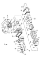
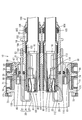
- FIG. 1 An exploded perspective view showing components of the lever-type connector of Embodiment 1
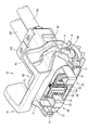
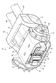
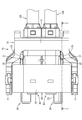
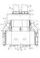
- a perspective view of a lever-type connector in which the lever is in the rotation start position The perspective view of the lever type connector which showed the state in which the lever is in the rotation end position.
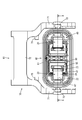
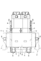
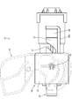
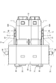
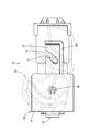
- Front view of a lever-type connector in which the lever is in the rotation start position AA line sectional view in FIG. 4
- Front view of a lever-type connector in which the lever is in the rotation end position BB line cross section in FIG. 6 Top view of the lever-type connector with the lever in the mated position CC sectional view in FIG. 8
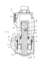
- Sectional drawing which showed the state which connected the male terminal to the female terminal in Embodiment 2, and made the contact pressure provision member be located in the high contact pressure position.
- Sectional drawing which showed the state which connected the male terminal to the female terminal in Embodiment 3, and made the contact pressure provision member be located in the high contact pressure position.
- the perspective view which showed a mode that a contact pressure provision member was moved by gear drive in Embodiment 4.
- the lever-type connector 10 includes a pair of contact pressure applying members 20, a pair of first seals 30, a front cover 40, a second seal 50, a female housing 60, a lever 70, and a pair of members.
- the terminal cover 80, the pair of shield shells 90, the pair of terminal-equipped electric wires 100, and the like are provided.
- the terminal-equipped electric wire 100 has a double-coated shielded electric wire 101, a female terminal 110 connected to the inner conductor constituting the shielded electric wire 101, an outer conductor 91 constituting the shielded electric wire 101, and a shield Underlay ring 103 and caulking ring 104 sandwiching the rear end of shell 90, third seal 105 in close contact with the outer peripheral surface of sheath 102 constituting shield wire 101, and back retainer 106 for preventing the third seal from coming off And is configured.
- the female terminal 110 includes an angular tube portion 112 having an elastic contact piece 111, and a wire connection portion 114 having a barrel portion 113 to be crimped to the internal conductor of the shield wire 101.
- the metal plate constituting 112 is thinner than the metal plate constituting the wire connection portion 114 and has high rigidity.
- the wire connection portion 114 has a terminal connection portion 115 inserted from the rear to the square tube portion 112, and the terminal connection portion 115 is connected to the male terminal 120 held by the male housing 130.
- the male terminal 120 of the present embodiment is a bus bar made of a conductive metal plate material.
- the resilient contact piece 111 has a chevron shape as a whole, and is configured to extend forward in a cantilever shape. More specifically, the elastic contact piece 111 is provided so as to be folded forward from the rear end of the peripheral wall portion 116 constituting the rectangular tube portion 112, and between the front end of the elastic contact piece 111 and the peripheral wall portion 116 , A gap is formed. A contact pressure applying unit 23 described later can enter into this gap from the front.
- the terminal connection portion 115 is disposed to face the apex portion of the elastic contact piece 111, and has a shape in which two places in front and rear are raised.
- the raised portion serves as a contact portion in contact with the male terminal 120.
- the two front and rear contact portions are arranged symmetrically at two front and rear positions with respect to the top of the resilient contact piece 111.
- the female terminal 110 is accommodated and held inside the terminal cover 80, and the terminal cover 80 is accommodated and held inside the shield shell 90.
- the shield shell 90 protrudes rearward beyond the rear end of the terminal cover 80, and is connected to the outer conductor 91 of the shield wire 101 at this protruding portion.
- the shield shell 90 and the outer conductor 91 of the shield wire 101 are integrated. It has been crimped.
- the rear end of the caulking ring 104 is fixed to the sheath 102 of the shield wire 101.
- the female housing 60 is made of synthetic resin and includes a hood portion 61 opening forward and a housing main body 63 disposed to penetrate through the back wall 62 of the hood portion 61.
- the housing main body 63 has a terminal cover 80
- a terminal cover accommodating portion 64 accommodated inside and a third seal accommodating portion 65 internally accommodating the third seal 105 are provided.
- the third seal 105 is in close contact with both the outer peripheral surface of the sheath 102 of the shield wire 101 and the inner peripheral surface of the third seal accommodating portion 65, and the backward movement is restricted by the back retainer 106.
- the entry of water from the rear into the interior of the third seal housing portion 65 is restricted.
- a second seal mounting wall 69 to which the second seal 50 is fitted is provided inside the hood portion 61.
- a front cover 40 is mounted on the front side of the second seal mounting wall 69. The front cover 40 restricts the second seal 50 from coming off the second seal mounting wall 69 in the forward direction.
- the male housing 130 enters between the hood portion 61 and the second seal mounting wall 69, the second seal 50 is in close contact with both the male housing 130 and the second seal mounting wall 69, and between the male and female housings 60 and 130. Water is restricted from entering the inside of the second seal mounting wall 69.
- the lever 70 has a substantially gate-like shape as a whole, and as shown in FIG. 16, a pair of cam plate portions 71 are connected by an operation portion 72.
- the cam plate portion 71 is provided with a cam groove 73 to which the cam pin 131 provided in the male housing 130 can enter.
- the cam groove 73 is provided in the female housing 60. It is distributed in a substantially arc shape centering on a turning hole 74 in which the moving shaft 66 is fitted. More specifically, the cam groove 73 is provided so as to be continuous with the fitting track 73A formed so as to be closer to the turning hole 74 as it goes from the inlet portion toward the back end side and from the turning hole 74 And the same distance of the rotation path 73B.
- a drive shaft 75 is provided on the cam plate portion 71 so as to project on the opposite side of the rotation groove 74 to the idle track 73 B of the cam hole 73.
- the drive shaft 75 is located closer to the rotation hole 74 than the operation portion 72, and the drive shaft 75 of one cam plate portion 71 and the drive shaft 75 of the other cam plate portion 71 face each other. It is considered to be a projecting aspect.
- the lever 70 is rotatably attached to the female housing 60 by fitting the pair of pivot shafts 66 into the pair of pivot holes 74 from the inside.
- the lever 70 is rotated from the rotation start position shown by the two-dot chain line in FIGS. 12 and 13 via the fitting completion position shown in FIGS. 8 and 9 as shown by the two-dot chain line in FIGS. It is possible to rotate until it reaches the end position.
- the inlet portion of the cam groove 73 is in a posture facing forward, and the cam pin 131 can be received in the cam groove 73.
- the lever 70 is rotated to the fitting completion position.
- the male and female housings 60, 130 reach the mated state.
- the cam pin 131 moves along the idle track 73B of the cam groove 73, but the fitting operation of the male and female housings 60 and 130 does not proceed, in other words, fitting The completed state is maintained.
- the contact pressure applying member 20 has a hook shape as a whole, and as shown in FIG. 1, a drive portion 22 provided with a drive track 21 for moving in the front-rear direction by engaging with the drive shaft 75;
- the contact pressure application part 23 which applies the contact pressure by pressing the elastic contact piece 111 of the terminal 110, and the connection part 24 which connects the drive part 22 and the contact pressure application part 23 are comprised.
- the driving portion 22 and the contact pressure applying portion 23 both protrude rearward from both side edges of the connecting portion 24 so as to be opposed to each other, and the driving portion 22 is longer than the contact pressure applying portion 23.
- a flange 25 is circumferentially provided at a central portion in the front-rear direction of the drive unit 22.
- a plurality of mounting holes 26 are provided through the flange 25 so that the plurality of mounting projections 31 provided on the first seal 30 are fitted to the plurality of mounting holes 26 so that the first seal 30 is formed of the flange 25. It is fixed to the back side.
- a drive track 27 is provided at a rear portion of the flange 25 in the drive unit 22. The drive track 27 is configured to extend diagonally forward from the upper edge of the drive portion 22.
- the drive unit 22 is inserted from the front into a through hole 67 provided through the back wall 62 of the hood unit 61.
- the drive portion 22 protruding rearward from the back wall 62 is mounted along the mounting portions 68 provided on the left and right sides of the outer peripheral surface of the third seal housing portion 65.
- the mounting portion 68 is provided with an L-shaped guide wall 68A for guiding the movement of the drive portion 22.
- the contact pressure applying member 20 is movable in the front-rear direction between the low contact pressure position shown in FIG. 5 and the high contact pressure position shown in FIG. 7.
- the flange 25 of the contact pressure applying member 20 is housed between the outer peripheral surface of the terminal cover housing portion 64 and the inner peripheral surface of the second seal mounting wall 69. Further, the first seal 30 is in close contact with both the outer peripheral surface of the terminal cover accommodating portion 64 and the outer peripheral surface of the second seal mounting wall 69. As a result, even if water tries to enter the inside of the hood portion 61 from the through hole 67, the water is stopped by the first seal 30.
- the drive portion 22 is accommodated between the mounting portion 68 and the lever 70, the contact pressure applying member 20 is deformed outward and the female is deformed. It is possible to prevent the housing 60 from being detached. Since the cam pin 131 of the male housing 130 moves along the idle track 73B of the cam groove 73 while the lever 70 is rotated from the fitting completion position to the rotation end position, the fitting operation of the male and female housings 60 and 130 is It does not progress.
- a contact pressure applying portion insertion hole 81 in which the contact pressure applying portion 23 is inserted from the front, and a male terminal insertion hole 82 in which the male terminal 120 is inserted from the front And are provided.
- the tip end of the contact pressure application part 23 enters the back side of the elastic contact piece 111 (opposite to the terminal connection part 115) through the contact pressure application part insertion hole 81 There is.
- the contact pressure applying part 23 presses the elastic contact piece 111 toward the terminal connection part 115 while sliding contact with the back side of the tip of the elastic contact piece 111.
- the resilient contact piece 111 is pressed to the terminal connection portion 115 side.
- the male terminal 120 enters between the elastic contact piece 111 and the terminal connection portion 115 through the male terminal insertion hole 82 in the state where the contact pressure applying portion 23 is in the low contact pressure position. Then, as shown in FIG. 20, due to the spring force of the elastic contact piece 111, the male terminal 120 comes into contact with the terminal connection portion 115 in a low contact pressure state. For this reason, the male terminal 120 and the terminal connection portion 115 do not cause contact wear, and the foreign matter removal effect by the wiping effect is exhibited. Then, as shown in FIG.
- the contact pressure applying member 20 is in the low contact pressure position before the male and female housings 60 and 130 are completely fitted, and the female terminal 110 contacts the male terminal 120 at a low contact pressure. Therefore, contact wear can be prevented.
- the contact pressure applying member 20 is moved to the high contact pressure position by the lever 70, the female terminal 110 contacts the male terminal 120 with high contact pressure. During this time, since the fitting operation of the male and female housings 60 and 130 is stopped, contact wear can be prevented even when the low pressure state is shifted to the high pressure state.
- the through hole 67 of the female housing 60 can be stopped with the first seal 30, and the fitting portion of the male and female housings 60, 130 can be stopped with the second seal 50, so that the present invention is applied to a waterproof connector. can do.
- the lever 70 has a cam groove 73, and the cam groove 73 engages with a cam pin 131 provided on the male housing 130 to make a fitting track 73A for performing a fitting operation, and the lever 70 is continued after the fitting is completed. It may be configured to have an idle track 73B that keeps the fitting operation stopped when moved. According to such a configuration, since the cam groove 73 has the fitting track 73A and the idle track 73B, the lever 70 is moved after the fitting of the male and female housings 60 and 130 is completed by the fitting track 73A. Even if this is done, the fitting operation does not proceed, and the male and female housings 60 and 130 can be maintained in the fitted complete state.
- the lever 70 has a drive shaft 75, and the contact pressure applying member 20 engages with the drive shaft 75 to provide a drive track 21 for moving from a low contact position to a high contact position. It is good also as composition provided with section 22 and contact pressure grant part 23 which presses female terminal 110, and applies contact pressure, and drive part 22 penetrates penetration hole 67, and is distributed. According to such a configuration, since the drive portion 22 is disposed at a position different from the contact pressure applying portion 23 pressing the female terminal 110, the first seal 30 is not restricted by the arrangement of the female terminal 110. Can be set.
- the female housing 60 has a mounting portion 68 to which the drive portion 22 is mounted, and after the fitting of the female housing 60 and the male housing 130 is completed, the driving portion 22 is between the mounting portion 68 and the lever 70. It may be configured to be accommodated. According to such a configuration, since the drive portion 22 is accommodated between the mounting portion 68 and the lever 70, the driving portion 22 is disengaged from the mounting portion 68 on the way from the low contact pressure position to the high contact pressure position. You can prevent.
- the lever-type connector 200 of the present embodiment is a modification of the configuration of the female terminal 110 of the lever-type connector 10 of the first embodiment, and the other components are the same as those of the first embodiment. It shall be used, and the explanation shall be omitted.
- the female terminal 210 of the present embodiment includes a terminal main body 211 and a secondary spring 212, and the terminal main body 211 is a primary wall disposed to face the bottom wall 213 and the bottom wall 213.
- a spring 214 and a pair of connection walls 215 connecting the bottom wall 213 and the primary spring 214 are provided.
- the primary spring 214 is formed to be closer to the bottom wall 213 from the front edge of the proximal end mounted on the upper edge of the pair of connection walls 215 toward the front, and the front end of the primary spring 214 and the front end of the bottom wall 213 Are substantially aligned in the front-rear direction.
- the secondary spring 212 has a rectangular cylindrical shape, and is disposed so as to surround all around the front end of the primary spring 214 and the front end of the bottom wall 213.
- a protrusion 216 is provided on the opposite wall of the secondary spring 212 opposite to the primary spring 214.
- the distance between the front end of the primary spring 214 and the bottom wall 213 is smaller than the thickness of the male terminal 220.
- the leading end of the male terminal 220 is provided with the taper 221 for guiding, the male terminal 220 can be smoothly inserted between the bottom wall 213 and the primary spring 214. As shown in FIG.
- the leading end of the contact pressure application unit 230 is provided with a taper 231 for guiding, so that the contact pressure application unit 230 can be smoothly inserted between the secondary spring 212 and the primary spring 214 and at the same time, the contact with the primary spring 214 is gentle. Contact pressure can be applied. As shown in FIG. 24, when the contact pressure application unit 230 is moved from the low contact pressure position to the high contact pressure position, the contact pressure application unit 230 is pushed between the protrusion 216 and the primary spring 214, and the contact pressure application unit 230. Thus, the primary spring 214 is pressed to the bottom wall 213 side.
- Embodiment 3 A third embodiment will now be described with reference to the drawing of FIG.
- the lever-type connector 300 of the present embodiment is the same as the first embodiment because the configuration of the contact pressure applying portion 23 of the lever-type connector 10 of the first embodiment is changed and the other configurations are the same.
- the code is used, and the description thereof is omitted.
- the contact pressure applying portion 310 of the present embodiment is configured to include a shaft portion 311 made of synthetic resin and a spike 312 made of metal.
- a spike 312 is formed so that the tip of the resilient contact piece 111 contacts in the region from the low contact position to the high contact position.
- the tip of the elastic contact piece 111 is in sliding contact with the spike 312 with a strong force, but the spike 312 is made of metal Therefore, even when the contact pressure application unit 310 is repeatedly inserted and removed, the resin does not wear as in the resin, and the elastic contact piece 111 receives a strong force for a long period of time at the high contact pressure position and compresses as the resin. There is no creep deformation. Therefore, it is possible to prevent the contact pressure decrease due to wear and compression creep deformation.
- the lever-type connector 400 of the present embodiment is the one in which the drive system of the contact pressure applying member 20 of the lever-type connector 10 of the first embodiment is changed from a cam mechanism to gear drive of a rack and pinion.
- the same reference numerals are used as in the first embodiment, and the description thereof is omitted.
- the contact pressure application member 410 of the present embodiment has a drive portion 412 provided with a drive gear 411 instead of the drive track 21.
- the drive gear 411 is configured to extend straight.
- the lever 420 has a rotating shaft 422 provided with a pinion gear 421 on the outer periphery. The drive gear 411 and the pinion gear 421 are engaged with each other, and the contact pressure applying member 410 can be moved in the front-rear direction by rotating the lever 420.
- the contact pressure application member 20 in which the drive unit 22 and the contact pressure application unit 23 are provided at different places via the connection unit 24 is illustrated, but the drive unit and the contact pressure application unit are integrated. It may be a contact pressure application member provided in series.
- the drive unit 22 is accommodated between the mounting portion 68 and the lever 70 after the fitting of the male and female housings 60 and 130 is completed, the driving unit is external to the mounting portion. It may be exposed.
- the first seal 30 is attached to the flange 25 of the contact pressure applying member 20, the first seal 30 is attached to the opening edge of the through hole 67 of the female housing 60. It is also good.
Landscapes
- Details Of Connecting Devices For Male And Female Coupling (AREA)
- Connector Housings Or Holding Contact Members (AREA)
Abstract
本明細書によって開示されるレバー式コネクタ10は、雌端子110と、雌ハウジング60と、雌ハウジング60に嵌合方向前方から取り付けられ、雌端子110を雄端子120に低接圧で接触させる低接圧位置と低接圧位置よりも嵌合方向後方に位置し雌端子110に接圧を付与することで雌端子110を雄端子120に高接圧で接触させる高接圧位置との間を移動可能とされた接圧付与部材20と、雌ハウジング60に移動可能に取り付けられ、嵌合完了後に接圧付与部材20を低接圧位置から高接圧位置へ移動させるレバー70と、接圧付与部材20が貫通して配された貫通孔67を止水する第1シール30と、雌ハウジング60と雄ハウジング130の嵌合部分を止水する第2シール50とを備えた構成とした。
Description
本明細書によって開示される技術は、レバー式コネクタに関する。
従来より、コネクタの嵌合時に雄タブが雌端子の弾性接触片に摺接することで接点摩耗を起こすことが知られており、この対策を施したコネクタとして、特許第4496475号公報(下記特許文献1)に記載のコネクタが知られている。このコネクタは、前方に開口したフード部を有する雄コネクタハウジングと、フード部内に嵌合可能な雌コネクタハウジングとを備え、雌コネクタハウジングには撓み可能なロックアームが設けられている。雌コネクタハウジングの内部には弾性接触片を有する雌端子金具が収容されており、ロックアームの下面には弾性接触片を押し下げる接圧受部が下方に突出して設けられている。ロックアームの上面にはロック突部が設けられており、雌コネクタハウジングをフード部内に嵌合させると、ロック突部がフード部の開口部に摺接しつつ、ロックアームが下方に押し下げられ、接圧受部が弾性接触片を押し下げた状態となる。この状態で雄タブが雌端子金具の角筒部内に進入すると、雄タブが弾性接触片に接触しないため、接点摩耗を防止することができる。
しかしながら、このコネクタでは、接圧受部を挿通させるための開口部を雌コネクタハウジングに設ける必要があり、開口部に止水構造を設けようとするとコネクタ全体の構造が複雑になるため、防水コネクタへの適用が困難となる。
そこで、接点摩耗を抑制しつつ防水を可能にしたコネクタとして、特開2008-218331号公報(下記特許文献2)に記載のコネクタが知られている。このコネクタは、雄ハウジングのフード部と雌ハウジングのハウジング本体部とに密着するシール部材を有しており、このシール部材によって雌雄両ハウジング間のシールをとることができるようになっている。雄ハウジングの奥壁部には、前方へ突出する一対の突出片が設けられており、雌端子の接触片の両側には、一対の張出部が側方に突出して設けられている。雌雄両ハウジングの嵌合直前に、一対の張出部が一対の突出片に乗り上げることでタブが接触片の接点部に高接圧で接触した状態となって両者が導通可能に接続される。これにより、嵌合途中にタブが接触片の接点部に摺接することによる接点摩耗を抑制することができる。
しかしながら、このコネクタでは、嵌合途中における接点摩耗を抑制することはできるものの、雌雄両ハウジングの嵌合直前に高接圧状態となり、やはり接点摩耗が発生することになるため、接点摩耗を抑制できているとは言いがたい。
特許文献1および2の課題については上述したとおりであり、防水コネクタに適用可能でかつ、接点摩耗を抑制できるコネクタについては実現できていないのが現状である。
本明細書によって開示されるレバー式コネクタは、雄ハウジングに保持された雄端子と接触可能な雌端子と、前記雌端子を内部に収容し、前記雄ハウジングと嵌合可能な雌ハウジングと、前記雌ハウジングに嵌合方向前方から取り付けられ、前記雌端子を前記雄端子に低接圧で接触させる低接圧位置と前記低接圧位置よりも嵌合方向後方に位置し前記雌端子に接圧を付与することで前記雌端子を前記雄端子に高接圧で接触させる高接圧位置との間を移動可能とされた接圧付与部材と、前記雌ハウジングに移動可能に取り付けられ、前記雄ハウジングを嵌合方向に移動させるとともに、嵌合完了後に前記接圧付与部材を前記低接圧位置から前記高接圧位置へ移動させるレバーと、前記雌ハウジングにおいて前記接圧付与部材が貫通して配された貫通孔を止水する第1シールと、前記雌ハウジングと前記雄ハウジングの嵌合部分を止水する第2シールとを備えた構成とした。
このような構成によると、雌雄両ハウジングの嵌合完了前には接圧付与部材が低接圧位置にあって、雌端子が雄端子に低接圧で接触しているため、接点摩耗を防ぐことができる。雌雄両ハウジングの嵌合完了後、接圧付与部材がレバーによって高接圧位置へ移動することに伴って雌端子が雄端子に高接圧で接触する。この間、雌雄両ハウジングの嵌合動作は停止したままであるから、低接圧状態から高接圧状態に移行しても接点摩耗を防ぐことができる。
また、雌ハウジングの貫通孔を第1シールで止水することができ、雌雄両ハウジングの嵌合部分を第2シールで止水することができるため、防水コネクタに適用することができる。
本明細書によって開示されるレバー式コネクタは、以下の構成としてもよい。
前記レバーはカム溝を有し、前記カム溝は、前記雄ハウジングに設けられたカムピンと係合することで嵌合動作を行わせる嵌合用軌道と、嵌合完了後に引き続き前記レバーを移動させた場合に嵌合動作を停止させたままにする空転軌道とを有している構成としてもよい。
このような構成によると、カム溝が嵌合用軌道と空転軌道とを有しているから、嵌合用軌道によって雌雄両ハウジングの嵌合が完了した後に引き続きレバーを移動させたとしても嵌合動作が進行することはなく、雌雄両ハウジングを嵌合完了状態に維持することができる。
前記レバーはカム溝を有し、前記カム溝は、前記雄ハウジングに設けられたカムピンと係合することで嵌合動作を行わせる嵌合用軌道と、嵌合完了後に引き続き前記レバーを移動させた場合に嵌合動作を停止させたままにする空転軌道とを有している構成としてもよい。
このような構成によると、カム溝が嵌合用軌道と空転軌道とを有しているから、嵌合用軌道によって雌雄両ハウジングの嵌合が完了した後に引き続きレバーを移動させたとしても嵌合動作が進行することはなく、雌雄両ハウジングを嵌合完了状態に維持することができる。
前記レバーは駆動軸を有し、前記接圧付与部材は、前記駆動軸と係合することで前記低接圧位置から前記高接圧位置への移動を行わせる駆動用軌道が設けられた駆動部と、前記雌端子を押圧して接圧を付与する接圧付与部とを備え、前記駆動部が前記貫通孔に貫通して配されている構成としてもよい。
このような構成によると、雌端子を押圧する接圧付与部とは異なる位置に駆動部が配されることになるから、雌端子の配置に制約を受けることなく第1シールを設定することができる。
このような構成によると、雌端子を押圧する接圧付与部とは異なる位置に駆動部が配されることになるから、雌端子の配置に制約を受けることなく第1シールを設定することができる。
前記雌ハウジングは、前記駆動部が装着される被装着部を有しており、前記雌ハウジングと前記雄ハウジングの嵌合完了後には、前記駆動部が前記被装着部と前記レバーの間に収容される構成とした。
このような構成によると、駆動部が被装着部とレバーの間に収容されるから、駆動部が低接圧位置から高接圧位置に向かう途中に被装着部から外れることを防ぐことができる。
このような構成によると、駆動部が被装着部とレバーの間に収容されるから、駆動部が低接圧位置から高接圧位置に向かう途中に被装着部から外れることを防ぐことができる。
本明細書によって開示される技術によれば、防水コネクタに適用可能でかつ、嵌合途中に低接圧状態を維持し、嵌合後に高接圧状態となるレバー式コネクタを提供することができる。
<実施形態1>
実施形態1を図1から図21の図面を参照しながら説明する。実施形態1におけるレバー式コネクタ10は、図1に示すように、一対の接圧付与部材20、一対の第1シール30、フロントカバー40、第2シール50、雌ハウジング60、レバー70、一対の端子カバー80、一対のシールドシェル90、一対の端子付き電線100などを備えて構成されている。
実施形態1を図1から図21の図面を参照しながら説明する。実施形態1におけるレバー式コネクタ10は、図1に示すように、一対の接圧付与部材20、一対の第1シール30、フロントカバー40、第2シール50、雌ハウジング60、レバー70、一対の端子カバー80、一対のシールドシェル90、一対の端子付き電線100などを備えて構成されている。
端子付き電線100は、図5に示すように、二重被覆のシールド電線101と、シールド電線101を構成する内部導体に接続された雌端子110と、シールド電線101を構成する外部導体91とシールドシェル90の後端部とを挟持した下敷きリング103およびかしめリング104と、シールド電線101を構成するシース102の外周面に密着した第3シール105と、第3シールの抜け止めを行うバックリテーナ106とを備えて構成されている。
雌端子110は、図5に示すように、弾性接触片111を有する角筒部112と、シールド電線101の内部導体に圧着されるバレル部113を有する電線接続部114とを備え、角筒部112を構成する金属板は、電線接続部114を構成する金属板よりも薄くて剛性が高いものとされている。電線接続部114は、角筒部112に対して後方から挿入された端子接続部115を有しており、この端子接続部115は、雄ハウジング130に保持された雄端子120に接続される。本実施形態の雄端子120は、導電性の金属板材からなるバスバーとされている。
弾性接触片111は全体として山形をなし、片持ち状をなして前方に延びる形態とされている。詳細に説明すると、角筒部112を構成する周壁部116の後端から前方に折り返すようにして弾性接触片111が設けられており、弾性接触片111の前端と周壁部116との間には、隙間が形成されている。この隙間に後述する接圧付与部23が前方から進入可能とされている。
端子接続部115は、弾性接触片111の頂点部分と対向する配置とされており、前後2カ所が隆起した形状とされている。この隆起部分は、雄端子120と接触する接点部となる。前後2カ所の接点部は、弾性接触片111の頂点を中心として前後2カ所で対称に配置されている。
雌端子110は端子カバー80の内部に収容、保持されており、端子カバー80はシールドシェル90の内部に収容、保持されている。シールドシェル90は、端子カバー80の後端よりも後方に突出しており、この突出した部分においてシールド電線101の外部導体91に接続されている。具体的には、シールドシェル90の内周に配された下敷きリング103とシールドシェル90の外周に配されたかしめリング104との間にシールドシェル90とシールド電線101の外部導体91とが一体となってかしめられている。また、かしめリング104の後端はシールド電線101のシース102に固着されている。
雌ハウジング60は合成樹脂製であって、前方に開口するフード部61と、フード部61の奥壁62を貫通して配されたハウジング本体63とを備え、ハウジング本体63は、端子カバー80を内部に収容する端子カバー収容部64と、第3シール105を内部に収容する第3シール収容部65とを備えている。第3シール105は、シールド電線101のシース102の外周面と第3シール収容部65の内周面との双方に密着しており、バックリテーナ106によって後方への移動が規制されている。これにより、第3シール収容部65の内部に後方から水が浸入することが規制されている。
フード部61の内部には、第2シール50が嵌着される第2シール装着壁69が周設されている。第2シール装着壁69の前側にはフロントカバー40が装着されている。このフロントカバー40により第2シール50が第2シール装着壁69から前方へ外れてしまうことが規制されている。フード部61と第2シール装着壁69との間に雄ハウジング130が進入すると、第2シール50が雄ハウジング130と第2シール装着壁69の双方に密着し、雌雄両ハウジング60、130の間から第2シール装着壁69の内部に水が浸入することが規制されている。
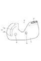
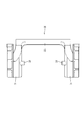
レバー70は全体として略門形をなし、図16に示すように、一対のカム板部71が操作部72によって連結された形状とされている。図17に示すように、カム板部71には、雄ハウジング130に設けられたカムピン131が進入可能なカム溝73が設けられており、このカム溝73は、雌ハウジング60に設けられた回動軸66が嵌合する回動孔74を中心として略円弧状に配されている。より詳細にはカム溝73は、入口部分から奥端部手前に向かうにつれて回動孔74に近づくように形成された嵌合用軌道73Aと、嵌合用軌道73Aに連なって設けられ回動孔74からの距離が等しい空転軌道73Bとによって構成されている。
図17および図18に示すように、カム板部71には、回動孔74に関してカム溝73の空転軌道73Bとは反対側に駆動軸75が突出して設けられている。駆動軸75は、操作部72よりも回動孔74側に位置しており、一方のカム板部71の駆動軸75と他方のカム板部71の駆動軸75とは互いに相手側に向けて突出する態様とされている。
レバー70は、一対の回動軸66が一対の回動孔74に内側から嵌合することで雌ハウジング60に対して回動可能に装着される。レバー70は、図12および図13において二点鎖線で示す回動開始位置から、図8および図9で示す嵌合完了位置を経由して、図14および図15において二点鎖線で示す回動終了位置に至るまでの間、回動可能とされている。回動開始位置においては、カム溝73の入口部分が前方を向いた姿勢とされ、カムピン131をカム溝73に受け入れ可能とされている。
雌雄両ハウジング60、130を浅く嵌合させてカムピン131をカム溝73の入口部分に進入させた後、レバー70を嵌合完了位置まで回動させると、カムピン131がカム溝73の嵌合用軌道73Aに沿って移動し、雌雄両ハウジング60、130が嵌合完了状態に至る。さらにレバー70を回動終了位置まで回動させると、カムピン131がカム溝73の空転軌道73Bに沿って移動するものの、雌雄両ハウジング60、130の嵌合動作は進行せず、言い換えると嵌合完了状態が維持されたままとなる。
接圧付与部材20は全体としてフック状をなし、図1に示すように、駆動軸75と係合することで前後方向の移動を行わせる駆動用軌道21が設けられた駆動部22と、雌端子110の弾性接触片111を押圧して接圧を付与する接圧付与部23と、駆動部22と接圧付与部23を連結する連結部24とを備えて構成されている。駆動部22と接圧付与部23はいずれも連結部24の両側縁から後方に突出して互いに対向する配置とされ、駆動部22のほうが接圧付与部23よりも長いものとされている。
駆動部22の前後方向における中央部には、フランジ25が周設されている。フランジ25には、複数の装着孔26が貫通して設けられ、第1シール30に設けられた複数の装着突起31が複数の装着孔26に嵌合することにより第1シール30がフランジ25の後面に固定されている。駆動部22におけるフランジ25の後方部分には、駆動用軌道27が設けられている。駆動用軌道27は、駆動部22の上縁から斜め前方に延びる形態とされている。
図5に示すように、駆動部22は、フード部61の奥壁62に貫通して設けられた貫通孔67に前方から挿通されている。奥壁62から後方に突出した駆動部22は、図1に示すように、第3シール収容部65の外周面における左右両側に設けられた被装着部68に沿って装着される。被装着部68は、駆動部22の移動を案内するL字状のガイド壁68Aを備えている。接圧付与部材20は、図5に示す低接圧位置と図7に示す高接圧位置との間を前後方向に移動可能とされている。また、接圧付与部材20のフランジ25は、端子カバー収容部64の外周面と第2シール装着壁69の内周面との間に収容されている。また、第1シール30は、端子カバー収容部64の外周面と第2シール装着壁69の外周面との双方に密着している。これにより、貫通孔67からフード部61の内部に水が浸入しようとしても、第1シール30により止水される。
図9に示すように、レバー70が嵌合完了位置にあって接圧付与部材20が低接圧位置にあるときには、駆動軸75が接圧付与部材20の駆動用軌道21の入口部分にわずかに進入した状態となる。ここからレバー70を回動終了位置まで回動させると、駆動軸75が駆動用軌道21に沿って移動することにより駆動部22が後方に引き込まれ、図11に示すように、接圧付与部材20が高接圧位置に至る。
図7および図14に示すように高接圧位置では、駆動部22が被装着部68とレバー70の間に収容されているため、接圧付与部材20が外側に開き変形するなどして雌ハウジング60から外れることを防ぐことができる。レバー70を嵌合完了位置から回動終了位置まで回動させる間、雄ハウジング130のカムピン131はカム溝73の空転軌道73Bに沿って移動するから、雌雄両ハウジング60、130の嵌合動作は進行しない。
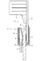
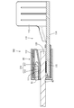
端子カバー80の前端部には、図2に示すように、接圧付与部23が前方から挿入される接圧付与部挿入孔81と、雄端子120が前方から挿入される雄端子挿入孔82とが設けられている。低接圧位置では図5に示すように、接圧付与部23の先端が接圧付与部挿入孔81を通って弾性接触片111の裏側(端子接続部115とは反対側)に進入している。高接圧位置では図7に示すように、接圧付与部23が弾性接触片111の先端部裏側に摺接しつつ弾性接触片111を端子接続部115側に押し込むため、接圧付与部23によって弾性接触片111が端子接続部115側に押圧される。
詳細には図19に示すように、接圧付与部23が低接圧位置にある状態で雄端子120が雄端子挿入孔82を通って弾性接触片111と端子接続部115との間に進入すると、図20に示すように、弾性接触片111のばね力によって雄端子120が低接圧状態で端子接続部115に接触した状態になる。このため、雄端子120および端子接続部115が接点摩耗を起こすことはなく、ワイピング効果による異物除去の効果は発揮される。そして、図21に示すように、接圧付与部23が高接圧位置にある状態では弾性接触片111を介した接圧付与部23からの押圧力によって雄端子120が高接圧状態で端子接続部115に接触した状態になる。このようにすれば、雌雄両ハウジング60、130の嵌合動作が完全に停止したまま雄端子120および端子接続部115に高い接圧を付与することができるため、接点摩耗を起こすことなく高い接圧により電気的な接触抵抗を低くすることができる。
以上のように本実施形態では、雌雄両ハウジング60、130の嵌合完了前には接圧付与部材20が低接圧位置にあって、雌端子110が雄端子120に低接圧で接触しているため、接点摩耗を防ぐことができる。雌雄両ハウジング60、130の嵌合完了後、接圧付与部材20がレバー70によって高接圧位置へ移動することに伴って雌端子110が雄端子120に高接圧で接触する。この間、雌雄両ハウジング60、130の嵌合動作は停止したままであるから、低接圧状態から高接圧状態に移行しても接点摩耗を防ぐことができる。
また、雌ハウジング60の貫通孔67を第1シール30で止水することができ、雌雄両ハウジング60、130の嵌合部分を第2シール50で止水することができるため、防水コネクタに適用することができる。
レバー70はカム溝73を有し、カム溝73は、雄ハウジング130に設けられたカムピン131と係合することで嵌合動作を行わせる嵌合用軌道73Aと、嵌合完了後に引き続きレバー70を移動させた場合に嵌合動作を停止させたままにする空転軌道73Bとを有している構成としてもよい。
このような構成によると、カム溝73が嵌合用軌道73Aと空転軌道73Bとを有しているから、嵌合用軌道73Aによって雌雄両ハウジング60、130の嵌合が完了した後に引き続きレバー70を移動させたとしても嵌合動作が進行することはなく、雌雄両ハウジング60、130を嵌合完了状態に維持することができる。
このような構成によると、カム溝73が嵌合用軌道73Aと空転軌道73Bとを有しているから、嵌合用軌道73Aによって雌雄両ハウジング60、130の嵌合が完了した後に引き続きレバー70を移動させたとしても嵌合動作が進行することはなく、雌雄両ハウジング60、130を嵌合完了状態に維持することができる。
レバー70は駆動軸75を有し、接圧付与部材20は、駆動軸75と係合することで低接圧位置から高接圧位置への移動を行わせる駆動用軌道21が設けられた駆動部22と、雌端子110を押圧して接圧を付与する接圧付与部23とを備え、駆動部22が貫通孔67に貫通して配されている構成としてもよい。
このような構成によると、雌端子110を押圧する接圧付与部23とは異なる位置に駆動部22が配されることになるから、雌端子110の配置に制約を受けることなく第1シール30を設定することができる。
このような構成によると、雌端子110を押圧する接圧付与部23とは異なる位置に駆動部22が配されることになるから、雌端子110の配置に制約を受けることなく第1シール30を設定することができる。
雌ハウジング60は、駆動部22が装着される被装着部68を有しており、雌ハウジング60と雄ハウジング130の嵌合完了後には、駆動部22が被装着部68とレバー70の間に収容される構成としてもよい。
このような構成によると、駆動部22が被装着部68とレバー70の間に収容されるから、駆動部22が低接圧位置から高接圧位置へ向かう途中に被装着部68から外れることを防ぐことができる。
このような構成によると、駆動部22が被装着部68とレバー70の間に収容されるから、駆動部22が低接圧位置から高接圧位置へ向かう途中に被装着部68から外れることを防ぐことができる。
<実施形態2>
次に、実施形態2を図22から図24の図面を参照しながら説明する。本実施形態のレバー式コネクタ200は、実施形態1のレバー式コネクタ10の雌端子110の構成を変更したものであって、その他の構成については同じであるため、実施形態1と同一の符号を用いるものとし、その説明を省略するものとする。
次に、実施形態2を図22から図24の図面を参照しながら説明する。本実施形態のレバー式コネクタ200は、実施形態1のレバー式コネクタ10の雌端子110の構成を変更したものであって、その他の構成については同じであるため、実施形態1と同一の符号を用いるものとし、その説明を省略するものとする。
本実施形態の雌端子210は、図22に示すように、端子本体211と、二次ばね212とを備え、端子本体211は、底壁213と、底壁213と対向して配された一次ばね214と、底壁213と一次ばね214を連結する一対の連結壁215とを備えている。一次ばね214は、一対の連結壁215の上縁に架設された基端部の前縁から前方に向かうほど底壁213に近づくように形成され、一次ばね214の前端と底壁213の前端とは前後方向においてほぼ揃う位置とされている。
二次ばね212は角筒状をなし、一次ばね214の前端付近と底壁213の前端付近とを全周に亘って囲む配置とされている。二次ばね212において一次ばね214と対向する対向壁部には、突起216が設けられている。一次ばね214の前端と底壁213の離間距離は、雄端子220の板厚よりも小さいものとされている。しかしながら、雄端子220の前端には、誘い込み用のテーパ221が設けられているため、底壁213と一次ばね214の間に雄端子220を円滑に挿入することができる。図23に示すように、接圧付与部23が低接圧位置に位置した状態で雄端子220が底壁213と一次ばね214の間に進入すると、一次ばね214が撓むことで接圧が発生する。このため、雄端子220と雌端子210は低接圧状態で接触し、接点摩耗を起こすことなくワイピング効果による異物除去の効果は発揮される。
接圧付与部230の前端には、誘い込み用のテーパ231が設けられているため、二次ばね212と一次ばね214の間に接圧付与部230を円滑に挿入できるとともに一次ばね214に緩やかに接圧を付与できるようになっている。図24に示すように、接圧付与部230を低接圧位置から高接圧位置に移動させると、接圧付与部230が突起216と一次ばね214の間に押し込まれ、接圧付与部230によって一次ばね214が底壁213側に押圧される。この状態では一次ばね214を介した接圧付与部230からの押圧力によって雄端子220が高接圧状態で底壁213に接触した状態になる。このようにすれば、雌雄両ハウジング60、130の嵌合動作が完全に停止したまま雄端子220および雌端子210に高い接圧を付与することができるため、やはり接点摩耗を起こすことはなく、高い接圧により電気的な接触抵抗を低くすることができる。
<実施形態3>
次に、実施形態3を図25の図面を参照しながら説明する。本実施形態のレバー式コネクタ300は、実施形態1のレバー式コネクタ10の接圧付与部23の構成を変更したものであって、その他の構成については同じであるため、実施形態1と同一の符号を用いるものとし、その説明を省略するものとする。
次に、実施形態3を図25の図面を参照しながら説明する。本実施形態のレバー式コネクタ300は、実施形態1のレバー式コネクタ10の接圧付与部23の構成を変更したものであって、その他の構成については同じであるため、実施形態1と同一の符号を用いるものとし、その説明を省略するものとする。
本実施形態の接圧付与部310は、合成樹脂製の軸部311と、金属製のスパイク312とを備えて構成されている。低接圧位置から高接圧位置に至る領域で弾性接触片111の先端部が接触するようにスパイク312が形成されている。
また、接圧付与部310が低接圧位置から高接圧位置へ移動する間、弾性接触片111の先端部がスパイク312に強い力で摺接することになるものの、スパイク312は金属製であるから、接圧付与部310を繰り返し挿抜した場合でも、樹脂のように摩耗することはなく、高接圧位置において長期間に亘って弾性接触片111から強い力を受けても樹脂のように圧縮クリープ変形することはない。したがって、摩耗や圧縮クリープ変形による接圧低下を防ぐことができる。
<実施形態4>
次に、実施形態4を図26の図面を参照しながら説明する。本実施形態のレバー式コネクタ400は、実施形態1のレバー式コネクタ10の接圧付与部材20の駆動方式をカム機構からラック・アンド・ピニオンのギア駆動に変更したものであって、その他の構成については同じであるため、実施形態1と同一の符号を用いるものとし、その説明を省略するものとする。
次に、実施形態4を図26の図面を参照しながら説明する。本実施形態のレバー式コネクタ400は、実施形態1のレバー式コネクタ10の接圧付与部材20の駆動方式をカム機構からラック・アンド・ピニオンのギア駆動に変更したものであって、その他の構成については同じであるため、実施形態1と同一の符号を用いるものとし、その説明を省略するものとする。
本実施形態の接圧付与部材410は、駆動用軌道21の代わりに駆動ギア411が設けられた駆動部412を有している。駆動ギア411は真っ直ぐに延びる形態とされている。一方、レバー420は、ピニオンギア421が外周に設けられた回動軸422を有している。駆動ギア411とピニオンギア421は互いに噛み合っており、レバー420を回動させることで接圧付与部材410を前後方向に移動させることができる。
<他の実施形態>
本明細書によって開示される技術は上記記述及び図面によって説明した実施形態に限定されるものではなく、例えば次のような種々の態様も含まれる。
(1)上記実施形態ではレバー70にカム溝73を設け、雄ハウジング130にカムピン131を設けているものの、レバーにカムピンを設け、雄ハウジングにカム溝を設けてもよい。
本明細書によって開示される技術は上記記述及び図面によって説明した実施形態に限定されるものではなく、例えば次のような種々の態様も含まれる。
(1)上記実施形態ではレバー70にカム溝73を設け、雄ハウジング130にカムピン131を設けているものの、レバーにカムピンを設け、雄ハウジングにカム溝を設けてもよい。
(2)上記実施形態ではレバー70に駆動軸75を設け、接圧付与部材20に駆動用軌道21を設けているものの、レバーに駆動用軌道を設け、接圧付与部材に駆動軸を設けてもよい。
(3)上記実施形態では駆動部22と接圧付与部23が連結部24を介して異なる箇所に設けられている接圧付与部材20を例示したが、駆動部と接圧付与部が一体に連なって設けられている接圧付与部材としてもよい。
(4)上記実施形態では雌雄両ハウジング60、130の嵌合完了後に駆動部22が被装着部68とレバー70の間に収容されるものを例示したが、駆動部が被装着部において外部に露出しているものとしてもよい。
(5)上記実施形態では回動式のレバー70を用いているものの、スライド式のレバーを用いてもよい。
(6)上記実施形態では角筒部112を有する箱形の雌端子110を用いているものの、円筒状の雌端子を用いてもよい。
(7)上記実施形態では第1シール30が接圧付与部材20のフランジ25に装着されているものの、第1シール30は雌ハウジング60の貫通孔67の開口縁部に装着されているものとしてもよい。
(8)上記実施形態1から3ではレバー70の回動によって雄ハウジング130との嵌合離脱動作と接圧付与部材の駆動とを行わせるようにしているものの、実施形態4と同様に、レバーの回動によって接圧付与部材の駆動のみを行わせるようにしてもよい。
10、200、300、400…レバー式コネクタ
20、410…接圧付与部材
21…駆動用軌道
22、412…駆動部
23、230、310…接圧付与部
30…第1シール
50…第2シール
60…雌ハウジング
67…貫通孔
68…被装着部
70、420…レバー
73…カム溝
73A…嵌合用軌道
73B…空転軌道
75…駆動軸
110、210…雌端子
120、220…雄端子
130…雄ハウジング
131…カムピン
20、410…接圧付与部材
21…駆動用軌道
22、412…駆動部
23、230、310…接圧付与部
30…第1シール
50…第2シール
60…雌ハウジング
67…貫通孔
68…被装着部
70、420…レバー
73…カム溝
73A…嵌合用軌道
73B…空転軌道
75…駆動軸
110、210…雌端子
120、220…雄端子
130…雄ハウジング
131…カムピン
Claims (4)
- 雄ハウジングに保持された雄端子と接触可能な雌端子と、
前記雌端子を内部に収容し、前記雄ハウジングと嵌合可能な雌ハウジングと、
前記雌ハウジングに嵌合方向前方から取り付けられ、前記雌端子を前記雄端子に低接圧で接触させる低接圧位置と前記低接圧位置よりも嵌合方向後方に位置し前記雌端子に接圧を付与することで前記雌端子を前記雄端子に高接圧で接触させる高接圧位置との間を移動可能とされた接圧付与部材と、
前記雌ハウジングに移動可能に取り付けられ、嵌合完了後に前記接圧付与部材を前記低接圧位置から前記高接圧位置へ移動させるレバーと、
前記雌ハウジングにおいて前記接圧付与部材が貫通して配された貫通孔を止水する第1シールと、
前記雌ハウジングと前記雄ハウジングの嵌合部分を止水する第2シールとを備えたレバー式コネクタ。 - 前記レバーはカム溝を有し、前記カム溝は、前記雄ハウジングに設けられたカムピンと係合することで嵌合動作を行わせる嵌合用軌道と、嵌合完了後に引き続き前記レバーを移動させた場合に嵌合動作を停止させたままにする空転軌道とを有している請求項1に記載のレバー式コネクタ。
- 前記レバーは駆動軸を有し、前記接圧付与部材は、前記駆動軸と係合することで前記低接圧位置から前記高接圧位置への移動を行わせる駆動用軌道が設けられた駆動部と、前記雌端子を押圧して接圧を付与する接圧付与部とを備え、前記駆動部が前記貫通孔に貫通して配されている請求項1または請求項2に記載のレバー式コネクタ。
- 前記雌ハウジングは、前記駆動部が装着される被装着部を有しており、前記雌ハウジングと前記雄ハウジングの嵌合完了後には、前記駆動部が前記被装着部と前記レバーの間に収容される請求項3に記載のレバー式コネクタ。
Priority Applications (3)
| Application Number | Priority Date | Filing Date | Title |
|---|---|---|---|
| DE112018005470.5T DE112018005470B4 (de) | 2017-09-28 | 2018-09-19 | Hebelverbinder |
| US16/636,569 US11025005B1 (en) | 2017-09-28 | 2018-09-19 | Lever-type connector |
| CN201880058642.3A CN111801851B (zh) | 2017-09-28 | 2018-09-19 | 杆式连接器 |
Applications Claiming Priority (2)
| Application Number | Priority Date | Filing Date | Title |
|---|---|---|---|
| JP2017188446A JP6880454B2 (ja) | 2017-09-28 | 2017-09-28 | レバー式コネクタ |
| JP2017-188446 | 2017-09-28 |
Publications (1)
| Publication Number | Publication Date |
|---|---|
| WO2019065387A1 true WO2019065387A1 (ja) | 2019-04-04 |
Family
ID=65902880
Family Applications (1)
| Application Number | Title | Priority Date | Filing Date |
|---|---|---|---|
| PCT/JP2018/034558 Ceased WO2019065387A1 (ja) | 2017-09-28 | 2018-09-19 | レバー式コネクタ |
Country Status (5)
| Country | Link |
|---|---|
| US (1) | US11025005B1 (ja) |
| JP (1) | JP6880454B2 (ja) |
| CN (1) | CN111801851B (ja) |
| DE (1) | DE112018005470B4 (ja) |
| WO (1) | WO2019065387A1 (ja) |
Cited By (1)
| Publication number | Priority date | Publication date | Assignee | Title |
|---|---|---|---|---|
| US20240022018A1 (en) * | 2020-08-28 | 2024-01-18 | Sumitomo Wiring Systems, Ltd. | Fitting device |
Families Citing this family (8)
| Publication number | Priority date | Publication date | Assignee | Title |
|---|---|---|---|---|
| GB2582834B (en) * | 2019-04-04 | 2023-04-12 | Danfoss Power Solutions Ii Technology As | Coupling device |
| KR102829875B1 (ko) * | 2020-12-28 | 2025-07-03 | 현대자동차주식회사 | 커넥터 조립체 |
| JP7533316B2 (ja) * | 2021-03-30 | 2024-08-14 | 住友電装株式会社 | レバー式コネクタ |
| JP7533315B2 (ja) * | 2021-03-30 | 2024-08-14 | 住友電装株式会社 | ワイヤハーネス及びコネクタ |
| JP7764282B2 (ja) | 2022-03-07 | 2025-11-05 | 日本航空電子工業株式会社 | コネクタ組立体 |
| JP7764283B2 (ja) | 2022-03-07 | 2025-11-05 | 日本航空電子工業株式会社 | コネクタ組立体 |
| DE102022132435A1 (de) * | 2022-12-07 | 2024-06-13 | Te Connectivity Solutions Gmbh | Tüllengehäuse zur Aufnahme eines Steckereinsatzes, Stecker und Steckverbinderanordnung |
| JP2024106182A (ja) * | 2023-01-26 | 2024-08-07 | 日本航空電子工業株式会社 | コネクタ組立体 |
Citations (2)
| Publication number | Priority date | Publication date | Assignee | Title |
|---|---|---|---|---|
| US6971894B2 (en) * | 2004-03-31 | 2005-12-06 | Jst Corporation | Dual action mechanical assisted connector |
| JP2017126406A (ja) * | 2016-01-12 | 2017-07-20 | 日立金属株式会社 | コネクタ |
Family Cites Families (17)
| Publication number | Priority date | Publication date | Assignee | Title |
|---|---|---|---|---|
| US5810612A (en) * | 1996-08-26 | 1998-09-22 | General Motors Corporation | Electrical connector with cam lock lever |
| US6439902B1 (en) * | 2000-11-13 | 2002-08-27 | Yazaki North America | Pre-set locks for a connector lever |
| US6565372B2 (en) * | 2001-02-27 | 2003-05-20 | Delphi Technologies, Inc. | Staged lock feature for an electrical connector assembly having a cam mating device |
| US6896531B2 (en) * | 2001-02-27 | 2005-05-24 | Delphi Technologies, Inc. | Electrical connector assembly |
| US6761568B2 (en) * | 2001-02-27 | 2004-07-13 | Delphi Technologies, Inc. | Electrical connector assembly |
| US6846191B2 (en) * | 2003-01-24 | 2005-01-25 | Delphi Technologies, Inc. | Electrical connector assembly |
| US6824406B1 (en) * | 2003-06-26 | 2004-11-30 | Delphi Technologies, Inc. | Electrical connector assembly |
| CN2689502Y (zh) * | 2003-10-29 | 2005-03-30 | 富士康(昆山)电脑接插件有限公司 | 具有凸轮机构的柔性线路板连接器 |
| JP4496475B2 (ja) * | 2005-02-01 | 2010-07-07 | 住友電装株式会社 | コネクタ |
| US7871282B2 (en) | 2006-03-13 | 2011-01-18 | Illinois Tool Works Inc. | Aircraft power connector with differential engagement and operational retention forces |
| US7241156B1 (en) * | 2006-07-31 | 2007-07-10 | Delphi Technologies, Inc. | Electrical connector with cam lever retainer |
| US7267583B1 (en) * | 2006-09-19 | 2007-09-11 | Delphi Technologies, Inc. | Electrical connection system |
| JP2008218331A (ja) | 2007-03-07 | 2008-09-18 | Sumitomo Wiring Syst Ltd | コネクタ |
| JP4947181B2 (ja) | 2010-04-13 | 2012-06-06 | 日立電線株式会社 | レバー式コネクタ |
| US8882521B2 (en) * | 2012-12-03 | 2014-11-11 | Delphi Technologies, Inc. | Lever type connector with enviromental cover |
| JP2015060628A (ja) * | 2013-09-17 | 2015-03-30 | 住友電装株式会社 | コネクタ |
| JP6086251B2 (ja) * | 2014-05-20 | 2017-03-01 | 住友電装株式会社 | コネクタ |
-
2017
- 2017-09-28 JP JP2017188446A patent/JP6880454B2/ja not_active Expired - Fee Related
-
2018
- 2018-09-19 CN CN201880058642.3A patent/CN111801851B/zh not_active Expired - Fee Related
- 2018-09-19 US US16/636,569 patent/US11025005B1/en not_active Expired - Fee Related
- 2018-09-19 WO PCT/JP2018/034558 patent/WO2019065387A1/ja not_active Ceased
- 2018-09-19 DE DE112018005470.5T patent/DE112018005470B4/de not_active Expired - Fee Related
Patent Citations (2)
| Publication number | Priority date | Publication date | Assignee | Title |
|---|---|---|---|---|
| US6971894B2 (en) * | 2004-03-31 | 2005-12-06 | Jst Corporation | Dual action mechanical assisted connector |
| JP2017126406A (ja) * | 2016-01-12 | 2017-07-20 | 日立金属株式会社 | コネクタ |
Cited By (2)
| Publication number | Priority date | Publication date | Assignee | Title |
|---|---|---|---|---|
| US20240022018A1 (en) * | 2020-08-28 | 2024-01-18 | Sumitomo Wiring Systems, Ltd. | Fitting device |
| US12355181B2 (en) * | 2020-08-28 | 2025-07-08 | Sumitomo Wiring Systems, Ltd. | Fitting device |
Also Published As
| Publication number | Publication date |
|---|---|
| CN111801851B (zh) | 2021-08-17 |
| JP2019067500A (ja) | 2019-04-25 |
| DE112018005470T5 (de) | 2020-06-25 |
| US20210159641A1 (en) | 2021-05-27 |
| JP6880454B2 (ja) | 2021-06-02 |
| DE112018005470B4 (de) | 2024-06-27 |
| US11025005B1 (en) | 2021-06-01 |
| CN111801851A (zh) | 2020-10-20 |
Similar Documents
| Publication | Publication Date | Title |
|---|---|---|
| WO2019065387A1 (ja) | レバー式コネクタ | |
| JP5500680B2 (ja) | レバー式電気コネクタ | |
| CN108352649B (zh) | 连接器 | |
| JP6424190B2 (ja) | レバー式コネクタ | |
| JP2019164945A (ja) | コネクタ | |
| WO2018142885A1 (ja) | シールド端子 | |
| JP2010246339A (ja) | 防水コネクタ | |
| JP2014165028A (ja) | コネクタ | |
| CN112436317B (zh) | 连接器 | |
| JP2019169244A (ja) | 防水コネクタ | |
| WO2017163802A1 (ja) | 基板用防水コネクタ | |
| WO2017159304A1 (ja) | レバー式コネクタ | |
| JP2002246088A (ja) | 可撓性平型ケーブル用防水コネクタ | |
| JP6243277B2 (ja) | シールドコネクタ | |
| JP2009252379A (ja) | シールドコネクタ | |
| JP5267374B2 (ja) | コネクタ | |
| JP2005174813A (ja) | コネクタ | |
| JP6617545B2 (ja) | コネクタ | |
| JP2008117552A (ja) | コネクタ | |
| JP2010257917A (ja) | ショート端子 | |
| WO2022054456A1 (ja) | シールドコネクタ | |
| JP6617577B2 (ja) | コネクタ | |
| JP7759553B2 (ja) | コネクタ | |
| US20250038457A1 (en) | Connector assembly and assembly method | |
| JP5098862B2 (ja) | シールドコネクタ |
Legal Events
| Date | Code | Title | Description |
|---|---|---|---|
| 121 | Ep: the epo has been informed by wipo that ep was designated in this application |
Ref document number: 18863569 Country of ref document: EP Kind code of ref document: A1 |
|
| 122 | Ep: pct application non-entry in european phase |
Ref document number: 18863569 Country of ref document: EP Kind code of ref document: A1 |