WO2019044262A1 - 車両用駆動装置 - Google Patents
車両用駆動装置 Download PDFInfo
- Publication number
- WO2019044262A1 WO2019044262A1 PCT/JP2018/027320 JP2018027320W WO2019044262A1 WO 2019044262 A1 WO2019044262 A1 WO 2019044262A1 JP 2018027320 W JP2018027320 W JP 2018027320W WO 2019044262 A1 WO2019044262 A1 WO 2019044262A1
- Authority
- WO
- WIPO (PCT)
- Prior art keywords
- vehicle
- support shaft
- motor
- housing
- drive unit
- Prior art date
Links
Images


Classifications
-
- B—PERFORMING OPERATIONS; TRANSPORTING
- B60—VEHICLES IN GENERAL
- B60K—ARRANGEMENT OR MOUNTING OF PROPULSION UNITS OR OF TRANSMISSIONS IN VEHICLES; ARRANGEMENT OR MOUNTING OF PLURAL DIVERSE PRIME-MOVERS IN VEHICLES; AUXILIARY DRIVES FOR VEHICLES; INSTRUMENTATION OR DASHBOARDS FOR VEHICLES; ARRANGEMENTS IN CONNECTION WITH COOLING, AIR INTAKE, GAS EXHAUST OR FUEL SUPPLY OF PROPULSION UNITS IN VEHICLES
- B60K5/00—Arrangement or mounting of internal-combustion or jet-propulsion units
- B60K5/12—Arrangement of engine supports
- B60K5/1208—Resilient supports
- B60K5/1216—Resilient supports characterised by the location of the supports relative to the motor or to each other
-
- B—PERFORMING OPERATIONS; TRANSPORTING
- B60—VEHICLES IN GENERAL
- B60G—VEHICLE SUSPENSION ARRANGEMENTS
- B60G11/00—Resilient suspensions characterised by arrangement, location or kind of springs
- B60G11/02—Resilient suspensions characterised by arrangement, location or kind of springs having leaf springs only
- B60G11/04—Resilient suspensions characterised by arrangement, location or kind of springs having leaf springs only arranged substantially parallel to the longitudinal axis of the vehicle
-
- B—PERFORMING OPERATIONS; TRANSPORTING
- B60—VEHICLES IN GENERAL
- B60G—VEHICLE SUSPENSION ARRANGEMENTS
- B60G9/00—Resilient suspensions of a rigid axle or axle housing for two or more wheels
- B60G9/003—Resilient suspensions of a rigid axle or axle housing for two or more wheels the axle being rigidly connected to a trailing guiding device
-
- B—PERFORMING OPERATIONS; TRANSPORTING
- B60—VEHICLES IN GENERAL
- B60K—ARRANGEMENT OR MOUNTING OF PROPULSION UNITS OR OF TRANSMISSIONS IN VEHICLES; ARRANGEMENT OR MOUNTING OF PLURAL DIVERSE PRIME-MOVERS IN VEHICLES; AUXILIARY DRIVES FOR VEHICLES; INSTRUMENTATION OR DASHBOARDS FOR VEHICLES; ARRANGEMENTS IN CONNECTION WITH COOLING, AIR INTAKE, GAS EXHAUST OR FUEL SUPPLY OF PROPULSION UNITS IN VEHICLES
- B60K1/00—Arrangement or mounting of electrical propulsion units
-
- B—PERFORMING OPERATIONS; TRANSPORTING
- B60—VEHICLES IN GENERAL
- B60K—ARRANGEMENT OR MOUNTING OF PROPULSION UNITS OR OF TRANSMISSIONS IN VEHICLES; ARRANGEMENT OR MOUNTING OF PLURAL DIVERSE PRIME-MOVERS IN VEHICLES; AUXILIARY DRIVES FOR VEHICLES; INSTRUMENTATION OR DASHBOARDS FOR VEHICLES; ARRANGEMENTS IN CONNECTION WITH COOLING, AIR INTAKE, GAS EXHAUST OR FUEL SUPPLY OF PROPULSION UNITS IN VEHICLES
- B60K17/00—Arrangement or mounting of transmissions in vehicles
- B60K17/04—Arrangement or mounting of transmissions in vehicles characterised by arrangement, location, or kind of gearing
- B60K17/16—Arrangement or mounting of transmissions in vehicles characterised by arrangement, location, or kind of gearing of differential gearing
-
- B—PERFORMING OPERATIONS; TRANSPORTING
- B60—VEHICLES IN GENERAL
- B60G—VEHICLE SUSPENSION ARRANGEMENTS
- B60G2200/00—Indexing codes relating to suspension types
- B60G2200/30—Rigid axle suspensions
-
- B—PERFORMING OPERATIONS; TRANSPORTING
- B60—VEHICLES IN GENERAL
- B60G—VEHICLE SUSPENSION ARRANGEMENTS
- B60G2202/00—Indexing codes relating to the type of spring, damper or actuator
- B60G2202/10—Type of spring
- B60G2202/11—Leaf spring
- B60G2202/112—Leaf spring longitudinally arranged
-
- B—PERFORMING OPERATIONS; TRANSPORTING
- B60—VEHICLES IN GENERAL
- B60G—VEHICLE SUSPENSION ARRANGEMENTS
- B60G2204/00—Indexing codes related to suspensions per se or to auxiliary parts
- B60G2204/40—Auxiliary suspension parts; Adjustment of suspensions
- B60G2204/418—Bearings, e.g. ball or roller bearings
-
- B—PERFORMING OPERATIONS; TRANSPORTING
- B60—VEHICLES IN GENERAL
- B60G—VEHICLE SUSPENSION ARRANGEMENTS
- B60G2300/00—Indexing codes relating to the type of vehicle
- B60G2300/50—Electric vehicles; Hybrid vehicles
-
- B—PERFORMING OPERATIONS; TRANSPORTING
- B60—VEHICLES IN GENERAL
- B60K—ARRANGEMENT OR MOUNTING OF PROPULSION UNITS OR OF TRANSMISSIONS IN VEHICLES; ARRANGEMENT OR MOUNTING OF PLURAL DIVERSE PRIME-MOVERS IN VEHICLES; AUXILIARY DRIVES FOR VEHICLES; INSTRUMENTATION OR DASHBOARDS FOR VEHICLES; ARRANGEMENTS IN CONNECTION WITH COOLING, AIR INTAKE, GAS EXHAUST OR FUEL SUPPLY OF PROPULSION UNITS IN VEHICLES
- B60K17/00—Arrangement or mounting of transmissions in vehicles
- B60K17/04—Arrangement or mounting of transmissions in vehicles characterised by arrangement, location, or kind of gearing
- B60K17/06—Arrangement or mounting of transmissions in vehicles characterised by arrangement, location, or kind of gearing of change-speed gearing
- B60K17/08—Arrangement or mounting of transmissions in vehicles characterised by arrangement, location, or kind of gearing of change-speed gearing of mechanical type
-
- B—PERFORMING OPERATIONS; TRANSPORTING
- B60—VEHICLES IN GENERAL
- B60K—ARRANGEMENT OR MOUNTING OF PROPULSION UNITS OR OF TRANSMISSIONS IN VEHICLES; ARRANGEMENT OR MOUNTING OF PLURAL DIVERSE PRIME-MOVERS IN VEHICLES; AUXILIARY DRIVES FOR VEHICLES; INSTRUMENTATION OR DASHBOARDS FOR VEHICLES; ARRANGEMENTS IN CONNECTION WITH COOLING, AIR INTAKE, GAS EXHAUST OR FUEL SUPPLY OF PROPULSION UNITS IN VEHICLES
- B60K1/00—Arrangement or mounting of electrical propulsion units
- B60K2001/001—Arrangement or mounting of electrical propulsion units one motor mounted on a propulsion axle for rotating right and left wheels of this axle
-
- B—PERFORMING OPERATIONS; TRANSPORTING
- B60—VEHICLES IN GENERAL
- B60Y—INDEXING SCHEME RELATING TO ASPECTS CROSS-CUTTING VEHICLE TECHNOLOGY
- B60Y2200/00—Type of vehicle
- B60Y2200/90—Vehicles comprising electric prime movers
- B60Y2200/91—Electric vehicles
-
- B—PERFORMING OPERATIONS; TRANSPORTING
- B60—VEHICLES IN GENERAL
- B60Y—INDEXING SCHEME RELATING TO ASPECTS CROSS-CUTTING VEHICLE TECHNOLOGY
- B60Y2400/00—Special features of vehicle units
- B60Y2400/86—Suspension systems
-
- B—PERFORMING OPERATIONS; TRANSPORTING
- B60—VEHICLES IN GENERAL
- B60Y—INDEXING SCHEME RELATING TO ASPECTS CROSS-CUTTING VEHICLE TECHNOLOGY
- B60Y2410/00—Constructional features of vehicle sub-units
- B60Y2410/10—Housings
Definitions
- the present invention relates to a vehicle drive device suitable for an electric vehicle.
- an object of the present invention is to provide a drive device for a vehicle that can cope with various vehicle types and can ensure the reliability of the motor.
- the present invention can be realized as the following application example.
- the vehicle drive device integrally includes a motor for driving the vehicle, a reduction gear connected to the motor, and a differential gear connected to the reduction gear to transmit the driving force of the motor to the drive wheels of the vehicle.
- a drive unit for a vehicle comprising a drive unit housing, the differential housing of the drive unit housing being connected, an axle housing integrally housing a drive shaft of a drive wheel, and a first connected to a vehicle body of the vehicle
- the motor-side housing of the drive unit housing are connected, and the second rotary support shaft is rotated.
- a second support portion for supporting the motor side housing on the vehicle body by swinging movement as a center, and the rail structure is configured such that the second rotation support shaft is movable in the vehicle longitudinal direction. did.
- the input is made to the drive unit housing
- the impact or load to be absorbed is absorbed by the peristaltic movement of the drive unit housing in response to the vertical displacement of the axle housing.
- the differential side housing with the axle housing is displaced in the vertical direction according to the displacement of the axle housing in the vertical direction and is connected to the second support rotary shaft A peristaltic motion about the second support rotational axis occurs, in which the motor-side housing displaces (moves) in the longitudinal direction of the vehicle above the rail structure.
- the peristaltic movement of the drive unit housing relieves the shock and load input to the drive unit housing, thereby protecting each device including the motor integrally attached to the drive unit housing from the applied shock and load.
- the drive unit housing structure adopting the rigid axle is relatively heavy, stress in the vehicle longitudinal direction is generated in the second support rotary shaft coupled to the motor side housing of the drive unit housing during peristaltic movement. Do. This may reduce the reliability of the motor.
- the second rotation support shaft is movable in the vehicle longitudinal direction, thereby relieving the stress in the vehicle longitudinal direction on the second support rotation shaft. Can ensure the reliability of the motor. From the above, such a vehicle drive device can not only be compatible with various vehicle models by adopting a rigid axle, but also can sufficiently ensure the reliability of the motor.
- the second rotation support shaft may be provided such that the rotation center of the motor and the rotation center of the second rotation support shaft coincide with each other.
- the rail structure can be displaced to the rail groove body by being supported by the second rotation support shaft and the rail groove body extending in both longitudinal directions provided in the vehicle body of the vehicle It may have with the circular bearing accommodated in.
- the rail structure may be a structure in which the rail groove body and the circular bearing are combined with the second rotation support shaft, and is simple and excellent in strength.
- the rail structure is displaceable in the rail groove body supported by the second rotation shaft and the rail grooves extending in the longitudinal direction provided in the vehicle body of the vehicle.
- the contained sliding block With such a configuration, a simple structure is required, and since the peristaltic movement of the drive unit housing is smoothly performed by the sliding block sliding on the rail groove body, the generation of noise can be suppressed. Moreover, by means of the sliding block, it is possible to sufficiently withstand the impact and load applied.
- the second support portion connects the second rotation support shaft and the motor side housing of the drive unit housing via the third rotation support shaft, and the third rotation support shaft
- the motor-side housing may be supported on the second rotation support shaft by connecting the second rotation support shaft so as to be rotatable around the third rotation support shaft.
- FIG. 6 is a cross-sectional view around the rail structure taken along the line CC in FIG. 5.
- the perspective view which shows the drive device for vehicles by which it became a mode concerning the 3rd embodiment of the present invention and was attached to vehicles.
- the side view of the drive device for vehicles seen from the arrow D in FIG. The perspective view which shows the structure which makes a drive unit housing rotatable with respect to a vehicle body. Sectional drawing in alignment with the EE line in FIG.
- FIG. 1 shows the lower part of the rear part of an electric powered vehicle (hereinafter referred to as a vehicle) of a commercial vehicle such as a truck, for example.
- a vehicle an electric powered vehicle
- the X direction in FIG. 1 indicates the vehicle longitudinal direction
- the Y direction indicates the vehicle width direction.
- a member 1 in FIG. 1 is a frame that constitutes a chassis.
- the frame 1 is configured in a ladder shape from a pair of side rails 3 extending in the longitudinal direction of the vehicle and a plurality of cross members (not shown) provided between the pair of side rails 3.
- a drum brake 5 and driving wheels 7 (only one side shown by a two-dot chain line) mounted on the drum brake 5 and the drum brake 5 are disposed on both sides of the side rail 3 in the vehicle width direction.
- spring members for example, leaf springs 9 extending in the longitudinal direction of the vehicle are disposed directly under the side rails 3 respectively.
- both ends of the leaf spring 9 have cylindrical portions 9a with bushes (not shown).
- a drive device 11 (corresponding to a vehicle drive device according to the present application) serving as a drive system of the electric vehicle is disposed between the rear portions of the side rails 3.
- the drive device 11 is configured as a drive unit 11 a by integrally assembling the devices of the drive system.
- the drive unit 11a has a box-shaped unit housing 13 (corresponding to the drive unit housing of the present application) extending in the longitudinal direction of the vehicle, and the front side of the unit housing 13 (the longitudinal direction of the vehicle)
- the motor 15 for driving the motor is assembled sideways, the reduction gear 17 is accommodated in the longitudinal middle portion of the unit housing 13, and the differential gear 19 is accommodated in the rear side (vehicle longitudinal direction) of the unit housing 13. That is, the unit housing 13 includes the motor 15, the reduction gear 17, and the differential gear 19.
- a cylindrical pair of axle housings 21 is connected to both sides of the differential side housing 13 a of the unit housing 13.
- the axle housing 21 is connected to the drum brake 5.
- a drive shaft 23 is rotatably accommodated in the interior of the axle housing 21, and the drive shaft 23 is integrally housed and supported in the axle housing 21.
- the drive shaft 23 movably connects between left and right output portions (not shown) of the differential gear 19 and the wheel mounting portion 5 a of the drum brake 5, and the driving force output from the differential gear 19 is a drive wheel It is structured to be transmitted to 7.
- an input portion (not shown) of the reduction gear 17 is movably connected to a motor shaft 15a of the motor 15, specifically to a motor shaft 15a attached to the rotor 15c.
- An output portion (not shown) of the reduction gear 17 is movably connected to an input portion (not shown) of the differential gear 19, and a driving force output from the motor 15 is transmitted to the differential gear 19 through the reduction gear 17. It is distributed from the differential gear 19 to the left and right drive shafts 23. That is, the drive unit 11a transmits the drive force of the motor 15 to the left and right drive wheels 7.
- the drive unit 11a (drive device 11) is supported by the side rail 3 which is a vehicle body, using a suspension device 25 using left and right leaf springs 9.
- the support structure is devised. Each part of this support structure is shown in the side view of FIG. 2 (arrow A in FIG. 1), the sectional view of FIG. 3 (BB in FIG. 2), and the exploded perspective view of FIGS. 4A and 4B. It is done.
- the drive unit 11a is disposed between the side rails 3 in a diagonal posture with the differential side on the lower side and the motor side on the upper side. .
- an axle housing 21 protruding from the differential side housing 13a of the drive unit 11a is supported at the central portion in the longitudinal direction of the left and right leaf springs 9.
- the axle housing 21 is supported by the leaf spring 9 using a saddle member and a U-shaped bolt (both not shown).
- each leaf spring 9 is rotatably supported by the lower portion of the side rail 3 (vehicle body) via a link mechanism 27.
- the link mechanism 27 is configured by a mechanism capable of extending and contracting in the vertical direction.
- the link mechanism 27 is rotatably supported by two sheet metal members 27a which are provided to project downward from the side rails 3 and which maintain a predetermined distance, and a lower portion of the sheet metal member 27 and the connection pin 27b. And two sheet metal members 27c.
- the cylindrical portion 9a on the rear side of the leaf spring 9 is interposed between the lower portions of the sheet metal members 27c.
- a pin member 27d (corresponding to the first rotation support shaft of the present application) is inserted between the two sheet metal members 27c and the cylindrical portion 9a so as to intersect them, and a shackle link for supporting the end of the leaf spring 9 is configured. That is, the pin member 27d constitutes a first support portion 29a that rotatably supports the cylindrical portion 9a of the leaf spring 9 with respect to the side rail 3 (vehicle body).
- the front end (vehicle longitudinal direction) end of the leaf spring 9 is rotatably supported by a bracket 30 mounted on the lower part of the side rail 3 opposite to the link mechanism 27 across the axle housing 21.
- the bracket 30 is composed of two sheet metal members.
- a cylindrical portion 9a on the front side of the leaf spring 9 is interposed between two sheet metal members.
- the pin member 30a (corresponding to the first rotation support shaft of the present application) is inserted so as to intersect the bracket 30 and the cylindrical portion 9a, and the cylindrical portion 9a of the leaf spring 9 is a side rail as in the rear side.
- a first support portion 29a rotatably supported by 3 (the vehicle body) is configured.
- a pair of rail structures 31 is installed at the lower part of each side frame 3 between the bracket 30 and the axle housing 21.
- the motor housing 13 b of the drive unit 11 a is supported by the rail structure 31.
- the rail structure 31 can roll freely in a substantially C-shaped rail groove formed by the rail groove 32 having a substantially C-shaped cross section and the rail groove 32.
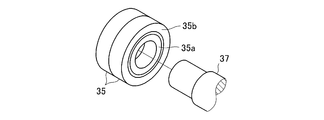
- a circular bearing 35 housed therein.
- the circular bearing 35 for example, two rows of roller bearings in which a plurality of rollers 35c are interposed between a circular inner race 35a and an outer race 35b are used.
- the rail groove 32 has a predetermined length in the X direction.
- Each rail groove body 32 is disposed so that the opening is directed inward in the vehicle width direction and extends in the vehicle longitudinal direction on both sides in the vehicle width direction of the motor side housing 13b (including the motor 15) of the drive unit 11a.
- These rail groove bodies 32 are attached to the lower part of the plate-like brackets 36 which project downward from the side rails 3 in a predetermined manner.
- the rail groove body 32 is disposed in the same direction as the side rail 3 at a point on the outer side in the vehicle width direction from the side rail 3.
- support shafts 37 are provided from the housing portion on the motor side which is both sides of the motor side housing 13b (drive unit 11a) and the end wall of the motor housing 15b forming the outer shell of the motor 15. (It corresponds to the 2nd rotation support axis of this application) is protrudingly provided.
- the support shaft 37 extending in the left-right direction (the vehicle width direction) has a length that reaches the left and right rail grooves 32.
- the support shafts 37 may protrude to both sides from substantially the same position as the rotation center of the motor shaft 15 a of the motor 15. That is, the support shaft 37 can be provided at a position substantially coinciding with the rotation center of the motor 15.
- a circular bearing 35 housed in the rail groove 32 is attached to the tip of each support shaft 37. Specifically, the tip end portion of the support shaft 37 is inserted into the inner race 35a of the circular bearing 35 (press fit), and the motor side housing 13b is rotatable relative to the side rail 3 (vehicle body) and movable in the longitudinal direction.
- the second support portion 29b is configured.
- the leaf spring 9 elastically supports the axle housing 21 with the pin members 27d and 30a as fixed fulcrums and the rail groove body 32 and the circular bearing 35 as movable fulcrums. That is, the axle housing 21 is elastically supported with the behavior that the movable fulcrum is displaced in the longitudinal direction of the vehicle.
- the drive unit 11a is pivotally displaced with the circular bearing 35 and the support shaft 37 as a peristaltic center, and the change in the fulcrum position of the circular bearing 35 then occurs in the rail groove body 32. Absorbed
- the drive unit 11a can be made to be able to make a peristaltic movement, and the shock transmitted from the axle housing 21 to the drive unit 11a as much as possible. And the load is not applied. Incidentally, the shock absorber attached to the drive unit 11a is omitted.
- the traveling of the vehicle is performed by the operation of the motor 15. That is, the driving force generated by the motor 15 is transmitted to the differential gear 19 through the reduction gear 17. Then, it is transmitted from the differential gear 19 to the left and right driving wheels 7 through the left and right drive shafts 23, and the vehicle travels on the road surface ⁇ .
- the motor-side housing 13b disposed obliquely upward of the drive unit 11a is connected to the circular bearing 35 in the rail groove 32 via the support shaft 37, and is supported so as to be rotatable in the vehicle longitudinal direction. ing.
- the differential side housing 13a is peristaltically displaced upward or downward with the motor side housing 13b as a peristaltic center.
- An arrow s in FIG. 2 indicates a peristaltic trajectory of the drive unit 11a at this time.
- the inner race 35a of the circular bearing 35 rotates or the circular bearing 35 is displaced in the front-rear direction on the rail groove 32 as the drive unit 11a swings.
- Arrow t in FIG. 2 indicates the direction in which the circular bearing 35 is displaced.
- the entire drive unit 11a performs a peristaltic motion with the circular bearing 35 and the support shaft 37 as a peristaltic fulcrum.
- the support shaft 37 connected with the motor side housing 13b of the drive unit housing 13 during the peristaltic movement is in the vehicle longitudinal direction Stress occurs.
- the reliability of the motor 15 may be reduced.
- the support shaft 37 is movable in the vehicle longitudinal direction, so that the stress in the vehicle longitudinal direction is relieved by the support shaft 37. The reliability of the motor 15 can be secured.
- such a driving device 11 driving device for a vehicle
- driving device for a vehicle can not only cope with various vehicle models by adopting a rigid axle, but also can sufficiently ensure the reliability of the motor 15.
- the rail structure 31 having such an effect is simple in structure and excellent in strength when the rail groove 32 and the circular bearing 35 are combined with the support shaft 37.
- Second Embodiment 5A, 5B and 6 show a second embodiment of the present invention.
- the present embodiment is a modification of the first embodiment, in which the support shaft 37 is movable in the longitudinal direction of the vehicle by using a sliding block 38.
- the structure adopting the sliding block 38 is substantially C-shaped formed by the rail groove body 32 as shown in FIGS. 5A, B and 6 (cross section along line CC in FIG. 5A).
- the sliding block 38 is slidably accommodated in the rail groove 32a of the first embodiment, and the circular bearing 35 used in the first embodiment is press-fit into the assembly opening 33a provided on the side surface of the sliding block 38.
- Ru for the sliding block 38, for example, a synthetic resin block that can slide smoothly in the rail groove 32a, for example, a nylon block whose surface is coated with a rubber as a lubricant is used.
- the sliding block 38 slides (displaces) the rail groove 32a smoothly, that is, the generation of noise can be suppressed. Moreover, the sliding block 38 has an advantage of being able to sufficiently withstand an impact or load applied.
- the same reference numerals as in the first embodiment denote the same parts in FIGS. 5A and 5B and FIG. 6, and a description thereof will be omitted.
- Third Embodiment 7 to 10 show a third embodiment of the present invention.
- the second support portion 29 b supports the motor side housing 13 b of the drive unit 11 a (drive device 11) so as to be movable around the center in the width direction of the frame 1. It is.
- the second supporting portion 29b includes a pair of rail structures 31 installed at the lower part of each side rail 3 and the side rails 3 so as to be movable in the vehicle longitudinal direction via the rail structures 31.
- a support shaft 50 (corresponding to a second rotation support shaft of the present application) to be supported, and a support shaft 50 for connecting between the support shaft 40 and the motor side housing 13b so as to be movable around the center of the frame 1 in the width direction.
- a structure combined with (corresponding to the third rotation support shaft of the present application) is used.
- the rail structure 31 is substantially C-shaped formed by the rail groove 32 having a substantially C-shaped cross section and the rail groove 32 as in the first embodiment. And a circular bearing 35 rotatably accommodated in the rail groove of
- the support shaft portion 40 is a disk-shaped housing portion 40a disposed at the center between the side rails 3 as shown in FIGS. 7 and 9, and a pair of cylinders extending a predetermined length from the housing portion 40a on both sides in the Y direction. It has a shaped portion 40b and a pair of support shafts 40c which project forward from the tip of each cylindrical portion 40b. The tip of each support shaft 40c is inserted into the inner race 35a of the circular bearing 35 so that the motor-side housing 13b can be moved in the front-rear direction with respect to the side rail 3 (vehicle body).
- a bearing accommodating portion 41 is formed at a central portion in the housing portion 40a.
- the bearing accommodating portion 41 is formed of a cylindrical wall penetrating in the X direction.
- a circular bearing 43 is inserted (or press-fitted) into the bearing accommodating portion 41.
- the circular bearing 43 is also a double-row roller bearing in which a plurality of rollers 43c are interposed between a circular inner race 43a and an outer race 43b.
- the opening on the opposite side of the cylindrical drive unit 11a is closed by the cover 44.
- an axial mounting seat 13c is formed at the end portion corresponding to the center between the side rails 3.
- One end of the support shaft 50 is attached to the shaft mounting seat 13 c via a bracket 47, and the other end of the support shaft 50 is protruded toward the bearing accommodation portion 41.
- a screw shaft portion 50a is provided at the center of the end face of the protruding support shaft 50 in a protruding manner.
- the support shaft 50 may be integrally formed with the motor side housing 13b.
- the other end of the support shaft 50 is fitted into the inner race 43 a of the circular bearing 43 as shown in FIGS. 9 and 10 and assembled to the support shaft 40.
- the screw shaft 50 a at the end of the support shaft 50 penetrates the lid 44 via a sleeve-shaped washer 45.
- a nut member 51 is screwed into the screw shaft portion 50 a which passes through the washer 45, and the support shaft 50 is rotatably connected to the support shaft portion 40.
- the support shaft 50 also corresponds to the movement of the support shaft portion 40 in the longitudinal direction of the vehicle.
- the structure in which the support shaft 50 is rotatably connected to the support shaft portion 40 allows torsional load and impact to be input to the differential side housing 13a including the axle housing 21 when, for example, one wheel passes over a protrusion on the road surface ⁇ In this case, a pivoting movement about the support shaft 50 is generated between the unit housing 13 and the vehicle body.
- the drive unit 11a From the axle rigid structure configured by combining the first support portion 29a and the second support portion 29b, the drive unit 11a can swing in the longitudinal direction and can swing in the width direction, thereby making the drive unit 11a as possible as possible with an axle The impact and load transmitted from the housing 21 are not applied.
- the drive force generated by motor 15 is transmitted to differential gear 19 through reduction gear 17. Then, it is transmitted from the differential gear 19 to the left and right drive wheels 7 through the left and right drive shafts 23, and the vehicle travels.
- a stepped portion (not shown) protruding upward is present on the road surface ⁇ , and that the same stepped portion passes over the stepped portion by the left and right driving wheels 7 during traveling.
- the impact and load accompanying the crossing over of the stepped portion are input from the left and right axle housings 21 to the differential side housing 13a disposed diagonally below the drive unit 11a.
- the motor-side housing 13b disposed obliquely upward of the drive unit 11a is connected to the circular bearing 35 in the rail groove 32 via the support shaft portion 40, and is supported so as to be displaceable in the vehicle longitudinal direction. . Therefore, the entire drive unit 11a is peristaltically displaced to the upper side (in the case of the step portion, the lower side) of the differential side housing 13a with the motor side housing 13b as the center of oscillation.
- An arrow L in FIG. 8 indicates a peristaltic trajectory of the drive unit 11a at this time.
- the entire drive unit 11a performs a peristaltic motion with the support shaft 40c as a peristaltic fulcrum.
- the shock and load input from the both axle housings 21 to the drive unit 11a are released (absorbed) by the peristaltic movement of the drive unit 11a that is generated along with the vertical displacement of the axle housing 21.
- each device including the motor 15 integrally attached to the unit housing 13 is protected from an impact or load applied.
- the drive unit 11a is rotatably supported with the support shaft 40c via the support shaft 50 extending in the longitudinal direction of the vehicle. For this reason, between the drive unit 11 a and the frame 1, relative rotational movement about the support shaft 50 occurs. Arrow N in FIG. 7 indicates the direction in which the rotational displacement occurs at this time.
- each device including the motor 15 integrally attached to the unit housing 13 is protected from an applied impact or load.
- the drive unit housing structure adopting a rigid axle is relatively heavy, stress in the longitudinal direction of the vehicle is generated in the support shaft portion 40 during peristaltic movement or rotational movement, and stress in the torsional direction of the support shaft 50 As a result, the support shaft portion 40 is movable in the longitudinal direction of the vehicle and the support shaft 50 is rotatably connected to the support shaft portion 40 as described above.
- stress in the longitudinal direction of the vehicle input to the support shaft portion 40 and stress in the torsional direction input to the support shaft 50 can be alleviated, and the reliability of the motor 15 can be secured.
- the same reference numerals as in the first embodiment denote the same parts in FIGS. 7 to 10, and a description thereof will be omitted.
- the present invention is not limited to the first, second, and third embodiments described above, and may be implemented in various ways without departing from the scope of the present invention.
- the rail groove body is disposed outside the side rail in the vehicle width direction.
- the rail groove body is disposed inside the vehicle side from the side rail.
- it may be disposed in the side rail.
- the present invention is applied to an electric commercial vehicle, the present invention is not limited to this, and may be applied to various vehicles including passenger cars.
Abstract
本発明の車両用駆動装置は、ディファレンシャル側ハウジング13aが連結され、駆動輪7のドライブシャフト23を一体的に収容するアクスルハウジング21と、車体3に連結された第1回転支持軸27bとアクスルハウジングとを連結し、第1回転支持軸を回転中心として揺動運動することによりアクスルハウジングを車体に支持する第1支持部29aと、車体にレール構造体31を介して支持された第2回転支持軸37とモータ側ハウジング13bとを弾性的に連結し、第2回転支持軸を回転中心として揺動運動することによりモータ側ハウジングを車体に支持する第2支持部29bとを含み、レール構造体が、第2回転支持軸が車両前後方向に可動となるように構成した。
Description
本発明は、電動車両に好適な車両用駆動装置に関する。
従来、車両用の駆動装置として、駆動用モータと減速機とがディファレンシャルギヤに一体的に設けられた駆動ユニットが知られている(例えば特許文献1を参照)。
トラック等の商用車においては車両仕様毎に様々な車格があり、その車格に応じて駆動装置が搭載可能な車幅も様々である。このような様々な車格に対応可能なアクスル構造として、車軸を格納するアクスルハウジングを用いたリジッドアクスル構造が挙げられる。
しかしながら、このようなリジッドアクスル構造において、前述の駆動ユニットを搭載する場合、駆動ユニットすべてがアクスルハウジングと共にバネ下支持となることから、駆動ユニットに搭載されるモータへの振動入力が大きくなり、モータの信頼性が低下するおそれがある。
そこで、本発明の目的は、様々な車格に対応可能で、モータの信頼性を確保することができる車両用駆動装置を提供することにある。
本発明は、以下の適用例として実現することができる。本適用例に係る車両用駆動装置は、車両を駆動するモータと、モータに連結する減速機と、減速機に連結し車両の駆動輪にモータの駆動力を伝達するディファレンシャルギアとを一体的に収容する駆動ユニットハウジングを備える車両用駆動装置であって、駆動ユニットハウジングのディファレンシャル側ハウジングが連結され、駆動輪のドライブシャフトを一体的に収容するアクスルハウジングと、車両の車体に連結された第1回転支持軸とアクスルハウジングとを弾性的に連結し、第1回転支持軸を回転中心として揺動運動することによりアクスルハウジングを車体に支持する第1支持部と、車両の車体にレール構造体を介して支持された第2回転支持軸と駆動ユニットハウジングのモータ側ハウジングとを連結し、第2回転支持軸を回転中心として揺動運動することによりモータ側ハウジングを前記車体に支持する第2支持部とを含み、レール構造体は、第2回転支持軸が車両前後方向に可動となるように構成されるものとした。
同構成により、例えば車両の走行中、第1支持部および第2支持部に弾性的に連結されたアクスルハウジングが路面の突起物を乗り越えるなどして上下方向で変位したとき、駆動ユニットハウジングへ入力される衝撃や荷重は、アクスルハウジングの上下方向の変位に応じた駆動ユニットハウジングの搖動運動によって吸収される。
すなわち、各機器が一体的に収められた駆動ユニットハウジングでは、アクスルハウジングの有るディファレンシャル側ハウジングが、アクスルハウジングの上下方向の変位にしたがい上下方向へ変位され、第2支持回転軸に連結されているモータ側ハウジングが、レール構造体上を車両前後方向に変位(可動)するという、第2支持回転軸を回転中心とした搖動運動が生じる。
この駆動ユニットハウジングの搖動運動により、駆動ユニットハウジングへ入力する衝撃や荷重は、逃がされるので、駆動ユニットハウジングに一体的に付くモータを含む各機器は、加わる衝撃や荷重から護られる。ここで、リジッドアクスルを採用する駆動ユニットハウジング構造体は比較的重量が大きいことから、搖動運動の際に駆動ユニットハウジングのモータ側ハウジングと連結する第2支持回転軸に車両前後方向の応力が発生する。これにより、モータの信頼性が低下するおそれがある。しかしながら、こうした車両用駆動装置におけるレール構造体で、第2回転支持軸が車両前後方向に可動となるような構成を採用することにより、第2支持回転軸に車両前後方向の応力を緩和することができ、モータの信頼性を確保することができる。以上から、こうした車両用駆動装置は、リジッドアクスルを採用することで様々な車格に対応可能できるだけでなく、モータの信頼性を十分に確保できる。
また、本適用例に係る車両用駆動装置において、第2回転支持軸が、モータの回転中心と当該第2回転支持軸の回転中心とが一致するように設けられていてもよい。
このような構成により、モータへ入力される衝撃や荷重を低減することができるため、モータの信頼性をより確実に確保することができる。
このような構成により、モータへ入力される衝撃や荷重を低減することができるため、モータの信頼性をより確実に確保することができる。
また、本適用例に係る車両用駆動装置において、レール構造体は、車両の車体に設けられた両前後方向に延びるレール溝体と、第2回転支持軸に支持されてレール溝体に変位可能に収容された円形ベアリングと有していてもよい。
このような構成によれば、レール構造体は、第2回転支持軸に、レール溝体、円形ベアリングを組み合わせた構造でよく、簡単で、強度的に優れたものとなる。
このような構成によれば、レール構造体は、第2回転支持軸に、レール溝体、円形ベアリングを組み合わせた構造でよく、簡単で、強度的に優れたものとなる。
また、本適用例に係る車両用駆動装置において、レール構造体は、車両の車体に設けられた両前後方向に延びるレール溝体と,第2回転軸に支持されてレール溝体に変位可能に収容されたスラディングブロックとを有していてもよい。
このような構成により、簡単な構造ですむうえ、駆動ユニットハウジングの搖動運動は、レール溝体をスライドするスライディングブロックで円滑に行われるので、騒音の発生を抑えることができる。そのうえ、スライディングブロック体を介することによって、加わる衝撃や荷重にも十分に耐え得る。
このような構成により、簡単な構造ですむうえ、駆動ユニットハウジングの搖動運動は、レール溝体をスライドするスライディングブロックで円滑に行われるので、騒音の発生を抑えることができる。そのうえ、スライディングブロック体を介することによって、加わる衝撃や荷重にも十分に耐え得る。
また、本適用例に係る車両用駆動装置において、第2支持部は、第2回転支持軸と駆動ユニットハウジングのモータ側ハウジングとを第3回転支持軸を介して連結し、第3回転支持軸は、第3回転支持軸を回転中心として回転可能となるように第2回転支持軸と連結することにより、モータ側ハウジングを第2回転支持軸に支持してもよい。
このような構成により、第2回転支持軸が車両前後方向に可動、さらに第3回転支持軸が第2回転支持軸と回転可能に連結される構成を採用することによって、第2支持回転軸に入力される車両前後方向の応力、第3支持回転軸に入力されるねじれ方向の応力は緩和でき、モータの信頼性を確保することができる。
このような構成により、第2回転支持軸が車両前後方向に可動、さらに第3回転支持軸が第2回転支持軸と回転可能に連結される構成を採用することによって、第2支持回転軸に入力される車両前後方向の応力、第3支持回転軸に入力されるねじれ方向の応力は緩和でき、モータの信頼性を確保することができる。
(第1の実施形態)
以下、本発明を図1から図4A,Bに示す第1の実施形態にもとづいて説明する。図1は、例えばトラック等の商用車の電動車両(以下、車両という)の後部の下部構造を示している。ちなみに図1中のX方向は、車両前後方向を示し、Y方向は、車両幅方向を示している。
以下、本発明を図1から図4A,Bに示す第1の実施形態にもとづいて説明する。図1は、例えばトラック等の商用車の電動車両(以下、車両という)の後部の下部構造を示している。ちなみに図1中のX方向は、車両前後方向を示し、Y方向は、車両幅方向を示している。
この電動車両の下部構造を説明すると、図1における部材1は、シャーシを構成するフレームである。フレーム1は、車両前後方向に延びる一対のサイドレール3と、一対のサイドレール3間に設けられた複数のクロスメンバ(図示しない)とからラダー形に構成される。
サイドレール3の車幅方向両側には、それぞれドラムブレーキ5、同ドラムブレーキ5に装着される駆動輪7(二点鎖線で片側だけ図示)が配置される。さらに各サイドレール3の直下には、ばね部材、例えば車両前後方向に延びるリーフスプリング9がそれぞれ配置される。ちなみにリーフスプリング9の両端部は、ブッシュ(図示しない)が付いた筒形部9aを有する。またサイドレール3の後部間には、電動車両の駆動系をなす駆動装置11(本願の車両用駆動装置に相当)が配置される。
駆動装置11は、駆動系の各機器を一体的に組み付けて駆動ユニット11aとしたものである。具体的には駆動ユニット11aは、車両前後方向に延びる箱形形状のユニットハウジング13(本願の駆動ユニットハウジングに相当)を有し、このユニットハウジング13の前部側(車両前後方向)に、車両を駆動するモータ15が横向きで組み付けられ、このユニットハウジング13の前後方向中間部に減速機17が収容され、このユニットハウジング13の後部側(車両前後方向)にディファレンシャルギヤ19が収容されてなる。つまり、ユニットハウジング13は、モータ15、減速機17、ディファレンシャルギヤ19を備えるものとなっている。
このユニットハウジング13のディファレンシャル側ハウジング13aの両側には、筒形の一対のアクスルハウジング21が連結される。アクスルハウジング21はドラムブレーキ5に連結される。アクスルハウジング21の内部にはドライブシャフト23が回転自在に収容され、ドライブシャフト23をアクスルハウジング21内に一体的に収め、かつ支持している。ドライブシャフト23は、ディファレンシャルギヤ19の左右の出力部(図示しない)とドラムブレーキ5の車輪装着部5aとの間を動力的に接続していて、ディファレンシャルギヤ19から出力される駆動力が駆動輪7に伝わる構造となっている。
また減速機17の入力部(図示しない)は、モータ15のモータ軸15a、具体的にはロータ15cに付くモータ軸15aと動力的に連結される。減速機17の出力部(図示しない)は、ディファレンシャルギヤ19の入力部(図示しない)と動力的に連結され、モータ15から出力される駆動力が、減速機17を通じディファレンシャルギヤ19へ伝達され、ディファレンシャルギヤ19から左右のドライブシャフト23へ振り分けられる。つまり、駆動ユニット11aは、モータ15の駆動力を左右の駆動輪7へ伝達するものである。
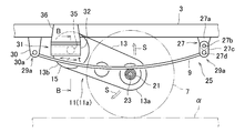
この駆動ユニット11a(駆動装置11)が、左右のリーフスプリング9を用いた懸架装置25を利用して、車体であるサイドレール3に支持させてある。本実施形態に係る車両用駆動装置では、この支持構造に工夫が施されている。この支持構造の各部が、図2の側面図(図1中の矢視A)、図3の断面図(図2中のB-B線)、図4Aおよび図4Bの分解斜視図にそれぞれ示されている。
図2~図4A,Bを参照して、同支持構造を説明すると、駆動ユニット11aは、サイドレール3間において、デファレンシャル側が下側、モータ側が上側となる車両前後方向斜めの姿勢で配置される。
そして、左右のリーフスプリング9の長手方向中央部に、駆動ユニット11aのディファレンシャル側ハウジング13aから張り出したアクスルハウジング21が支持される。例えばアクスルハウジング21は、サドル部材およびU形ボルト(いずれも図示しない)を用いてリーフスプリング9に支持される。
各リーフスプリング9の後部側(車両前後方向)の端部は、リンク機構27を介してサイドレール3(車体)の下部に回動自在に支持される。具体的にはリンク機構27は、上下方向に伸縮変位可能な機構で構成される。例えばリンク機構27は、サイドレール3から下方へ張り出すように設けた所定の間隔を保持した二枚の板金部材27aと、同板金部材27の下部と連結ピン27bを介して回動自在に支持される二枚の板金部材27cとで構成される。板金部材27cの下部間に、リーフスプリング9の後部側の筒形部9aが介在される。
二枚の板金部材27c、筒形部9a間には、これらと交差するようにピン部材27d(本願の第1回転支持軸に相当)が挿通され、リーフスプリング9端を支持するシャックルリンクを構成している。つまり、ピン部材27dにて、リーフスプリング9の筒形部9aをサイドレール3(車体)に対し回転自在に支持する第1支持部29aを構成している。
リーフスプリング9の前部側(車両前後方向)の端部は、アクスルハウジング21を挟んだ上記リンク機構27とは反対側のサイドレール3の下部に据え付けられたブラケット30に回転自在に支持されている。具体的にはブラケット30は、二枚の板金部材から構成される。二枚の板金部材間にリーフスプリング9の前部側の筒形部9aが介在される。そして、ブラケット30、筒形部9aと交差するようにピン部材30a(本願の第1回転支持軸に相当)が挿通され、後部側のときと同様、リーフスプリング9の筒形部9aをサイドレール3(車体)に対し回転自在に支持する第1支持部29aを構成している。
またブラケット30とアクスルハウジング21との間における各サイドレーム3の下部には、一対のレール構造体31が据え付けられている。このレール構造体31に、駆動ユニット11aのモータ側ハウジング13bが支持されている。
この支持構造を、図3および図4A,Bを参照して説明する。まずレール構造体31について説明すると、例えばレール構造体31は、断面が略C形をなすレール溝体32と、同レール溝体32で形成される略C形のレール溝内に転動自在に収容された円形ベアリング35とを有している。ちなみに円形ベアリング35には、例えば円形のインナレース35aとアウタレース35bとの間に複数のローラ35cを介装した二列のローラベアリングが用いられる。
レール溝体32は、X方向において所定の長さをもつ。各レール溝体32は、駆動ユニット11aのモータ側ハウジング13b(モータ15を含む)の車幅方向両側で、開口が車幅方向内側に向き、車両前後方向に延びるように配置される。これらレール溝体32が、各サイドレール3から下側へ所定に張り出した板状のブラケット36の下部に取着されている。ここではレール溝体32は、サイドレール3から車幅方向外側となる地点に、サイドレール3と同方向の向きで配置してある。
一方、図1に示されるようにモータ側ハウジング13b(駆動ユニット11a)の両側部となる、モータ側のハウジング部分と、モータ15の外郭をなすモータハウジング15bの端壁からは、それぞれ支持軸37(本願の第2回転支持軸に相当)が突設されている。左右方向(車幅方向)に延びる支持軸37は、左右のレール溝体32に届く長さ寸法をもつ。支持軸37は、いずれもモータ15のモータ軸15aの回転中心と略同じ位置から両側方へ突き出ていてもよい。つまり、支持軸37は、モータ15の回転中心と略一致する位置に設けることができる。
各支持軸37の先端部には、レール溝体32内に収めた円形ベアリング35が取着される。具体的には支持軸37の先端部は、円形ベアリング35のインナレース35a内に嵌挿され(圧入)、モータ側ハウジング13bを、サイドレール3(車体)に対し回転自在、前後方向に可動にする第2支持部29bを構成している。
これにより、路面αに突起物を乗り越えるときなどの際、アクスルハウジング21を含むディファレンシャル側ハウジング13aを可動側として、駆動ユニット11a全体が支持軸37を中心に搖動運動される構造としている。
具体的にはリーフスプリング9は、ピン部材27d,30aを固定支点、レール溝体32や円形ベアリング35を可動支点として、アクスルハウジング21を弾性支持する。つまりアクスルハウジング21は、可動支点が車両前後方向へ変位するという挙動を伴いながら弾性支持される。このアクスルハウジング21の上下方向の動きに連動して駆動ユニット11aが、円形ベアリング35、支持軸37を搖動中心として搖動変位し、そのとき生ずる円形ベアリング35の支点位置の変化がレール溝体32で吸収される。
つまり、第1支持部29a,第2支持部29b、レール構造体31を組み合わせて構成したアクスルリジッド構造から、駆動ユニット11aを搖動運動可能にして、駆動ユニット11aに、できるだけアクスルハウジング21から伝わる衝撃や荷重が加わらずにすむようにしている。ちなみに、駆動ユニット11aに付くショックアブソーバは省略している。
つぎに、このように構成された駆動装置11の作用について説明する。車両の走行は、モータ15の作動で行われる。すなわち、モータ15が発生する駆動力は、減速機17を通じてディファレンシャルギヤ19に伝わる。そして、ディファレンシャルギヤ19から、左右のドライブシャフト23を通じて左右の駆動輪7へ伝わり、車両が路面α上を走行する。
石などの突起物(図示しない)が路面αに有ると、リーフスプリング9が上側へ変位したりリーフスプリング9自身が上側へ弾性変形して、駆動輪7は突起物を乗り越える。この突起物の乗り越えに伴う衝撃や荷重は、アクスルハウジング21から、駆動ユニット11aの斜め下側に配置されるディファレンシャル側ハウジング13aへ入力される。
このとき駆動ユニット11aの斜め上側に配置されるモータ側ハウジング13bは、支持軸37を介して、レール溝体32内の円形ベアリング35に接続され、回転方向、車両前後方向へ変位可能に支持されている。このため、駆動ユニット11a全体は、モータ側ハウジング13bを搖動中心として、ディファレンシャル側ハウジング13aが上側あるいは下側へと搖動変位する。図2中の矢印sは、このときの駆動ユニット11aの搖動軌跡を示す。
この駆動ユニット11aの搖動に伴い円形ベアリング35は、インナレース35aが回転したり、円形ベアリング35がレール溝体32上を前後方向に変位する。図2中の矢印tは、円形ベアリング35が変位する方向を示している。すると、駆動ユニット11a全体は、円形ベアリング35、支持軸37を搖動支点として搖動運動する。
これにより、アクスルハウジング21から駆動ユニット11aへ入力される衝撃や荷重は、アクスルハウジング21の上下方向の変位に伴い生ずる駆動ユニット11aの搖動運動によって、逃がされる(吸収)。
すなわち、リジッドアクスルを採用する駆動ユニット11a(駆動ユニットハウジング構造体)は比較的重量が大きいことから、搖動運動の際に駆動ユニットハウジング13のモータ側ハウジング13bと連結する支持軸37に車両前後方向の応力が発生する。これにより、モータ15の信頼性が低下するおそれがある。しかしながら、こうした駆動装置11(車両用駆動装置)におけるレール構造体31で、支持軸37が車両前後方向に可動となるような構成を採用したので、支持軸37にて車両前後方向の応力を緩和することができ、モータ15の信頼性を確保することができる。
それ故、こうした駆動装置11(車両用駆動装置)は、リジッドアクスルを採用することで様々な車格に対応可能できるだけでなく、モータ15の信頼性を十分に確保できる。
また、支持軸37とモータ15の回転中心とが一致させた場合は、より効果的にモータ15(駆動ユニット11a)に入力される衝撃や荷重を低減することができる。そのうえ、こうした効果をもたらすレール構造体31は、支持軸37に、レール溝体32、円形ベアリング35を組み合わせた場合、簡単な構造ですみ、強度的にも優れる。
(第2の実施形態)
図5A、図5Bおよび図6は、本発明の第2の実施形態を示す。本実施形態は、第1の実施形態の変形例で、スライディングブロック38を用いて、支持軸37を車両前後方向に可動するようにしたものである。
図5A、図5Bおよび図6は、本発明の第2の実施形態を示す。本実施形態は、第1の実施形態の変形例で、スライディングブロック38を用いて、支持軸37を車両前後方向に可動するようにしたものである。
具体的には、スライディングブロック38を採用した構造は、図5A,Bおよび図6(図5A中のC-C線に沿う断面)に示されるようにレール溝体32で形成された略C形のレール溝32a内にスライディングブロック38を摺動自在に収容し、同スライディングブロック38の側面に設けた組付用開口33aに、第1の実施形態で用いた円形ベアリング35を圧入して構成される。スライディングブロック38には、例えばレール溝32a内をスムースにスライド可能な合成樹脂製のブロック、例えば表面に潤滑材としてラバーコーティングが施されたナイロン製のブロックが用いられる。
こうしたレール構造体31にスライディングブロック38を収容した構造は、スライディングブロック38がレール溝32aを円滑、すなわちスムースにスライド(変位)するため、騒音の発生を抑えられる。そのうえ、スライディングブロック38を介することによって、加わる衝撃や荷重にも十分に耐え得る利点もある。なお、図5A,Bおよび図6において第1の実施形態と同じ部分には同一符号を付して、その説明を省略した。
(第3の実施形態)
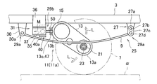
図7から図10は、本発明の第3の実施形態を示す。本実施形態は、第1の実施形態に加えて、第2支持部29bが、駆動ユニット11a(駆動装置11)のモータ側ハウジング13bを、フレーム1の幅方向中心回りに可動するよう支持したものである。
同構造を説明すると、第2支持部29bには、各サイドレール3の下部に据え付けた一対のレール構造体31と、レール構造体31を介して車両前後方向に可動となるようサイドレール3に支持される支持軸部40(本願の第2回転支持軸に相当)と、フレーム1の幅方向中心回りに可動となるよう支持軸部40とモータ側ハウジング13bとの間を連結する支持軸50(本願の第3回転支持軸に相当)とを組み合わせた構造が用いられる。
具体的には図9に示されるようにレール構造体31は、第1の実施形態と同様、断面が略C形をなすレール溝体32と、同レール溝体32で形成される略C形のレール溝内に転動自在に収容された円形ベアリング35とを有している。
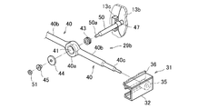
支持軸部40は、図7および図9に示されるようにサイドレール3間の中央に配置される円盤形のハウジング部40aと、同ハウジング部40aからY方向両側へ所定長さ延びる一対の筒形部40bと、各筒形部40bの先端部から前方へ突き出る一対の支持軸40cを有している。そして、各支持軸40cの先端部が、円形ベアリング35のインナレース35a内に嵌挿され、モータ側ハウジング13bを、サイドレール3(車体)に対し前後方向に可動できるようにしている。
これにより、両輪が路面αに有る突起物を乗り越えるときなどの際、アクスルハウジング21を含むディファレンシャル側ハウジング13aを可動側として、駆動ユニット11a全体が支持軸40cを中心に搖動運動される。
また図9および図10に示されるようにハウジング部40a内の中央部にはベアリング収容部41が形成されている。このベアリング収容部41は、X方向において貫通する筒形壁から形成される。このベアリング収容部41内には、円形ベアリング43が嵌挿(あるいは圧入)される。円形ベアリング43も、円形のインナレース43aとアウタレース43bとの間に複数のローラ43cを介装した二列のローラベアリングが用いられる。ちなみに筒形部の駆動ユニット11a側と反対側の開口は、蓋体44で閉じられる。
一方、図7~図9に示されているようにモータ側ハウジング13bの端部のうち、例えばサイドレール3間の中心と対応する端部分には、軸取付座13cが形成されている。軸取付座13cには、ブラケット47を介して、上記支持軸50の一端部が取り付けられ、支持軸50の他端部をベアリング収容部41へ向かって突出させている。突き出た支持軸50の端面中央には、ねじ軸部50aが突設されている。なお、軸取付座13cを設けない場合、支持軸50はモータ側ハウジング13bと一体に形成されていてもよい。
支持軸50の他端部は、図9および図10に示されるように円形ベアリング43のインナレース43a内に嵌挿されて、支持軸部40に組み付く。支持軸50端のねじ軸部50aは、スリーブ形のワッシャ45を介して、蓋体44を貫通する。ワッシャ45を貫通したねじ軸部50aには、ナット部材51がねじ込まれ、支持軸50を支持軸部40に対し回転可能に連結している。もちろん、支持軸50は支持軸部40の車両前後方向の動きにも対応している。
こうした支持軸50を支持軸部40に回動可能に連結する構造により、路面αに片輪が突起物を乗り越えるときなど、アクスルハウジング21を含むディファレンシャル側ハウジング13aにねじり方向の荷重や衝撃が入力された場合、ユニットハウジング13と車体との間において、支持軸50を回転中心とした回動運動が生じる構造にしている。
こうした第1支持部29a、第2支持部29bを組み合わせて構成したアクスルリジッド構造から、駆動ユニット11aを前後方向に搖動運動可能、幅方向に回動運動可能にして、駆動ユニット11aに、できるだけアクスルハウジング21から伝わる衝撃や荷重が加わらずにすむようにしている。
すなわち、このように構成された駆動装置11の作用について説明すると、モータ15が発生する駆動力は、減速機17を通じてディファレンシャルギヤ19に伝わる。そして、ディファレンシャルギヤ19から、左右のドライブシャフト23を通じて左右の駆動輪7へ伝わり、車両は走行する。
例えば上側へ突き出た段付部(図示しない)が路面αに有り、走行中、同段付部を左右駆動輪7の両輪で段付部を乗り越えたとする。このとき、段付部の乗り越えに伴う衝撃や荷重は、左右両側のアクスルハウジング21から、駆動ユニット11aの斜め下側に配置されるディファレンシャル側ハウジング13aへ入力される。
このとき駆動ユニット11aの斜め上側に配置されるモータ側ハウジング13bは、支持軸部40を介して、レール溝体32内の円形ベアリング35に接続され、車両前後方向へ変位可能に支持されている。このため、駆動ユニット11a全体は、モータ側ハウジング13bを搖動中心として、ディファレンシャル側ハウジング13aが上側(段差部の場合、下側)へと搖動変位する。図8中の矢印Lは、このときの駆動ユニット11aの搖動軌跡を示す。
この駆動ユニット11aの搖動に伴い円形ベアリング35は、インナレース35aが回転したり、円形ベアリング35がレール溝体32上を前後方向に変位したりする。図8中の矢印Mは、このときの円形ベアリング35が変位する方向を示している。
すると、駆動ユニット11a全体は、支持軸40cを搖動支点として搖動運動する。
すると、駆動ユニット11a全体は、支持軸40cを搖動支点として搖動運動する。
両アクスルハウジング21から駆動ユニット11aへ入力される衝撃や荷重は、第1の実施形態と同様、アクスルハウジング21の上下方向の変位に伴い生ずる駆動ユニット11aの搖動運動によって、逃がされる(吸収)。これにより、ユニットハウジング13に一体的に付くモータ15を含む各機器は、加わる衝撃や荷重から護られる。
また走行中、路面αに有る突起物(図示しない)を駆動輪7の片側(片輪)が乗り越えたとする。このとき、突起物の乗り越えに伴う衝撃や荷重は、左右片側のアクスルハウジング21から、駆動ユニット11aの斜め下側に配置されるディファレンシャル側ハウジング13aへ入力される。
このとき駆動ユニット11aは、車両前後方向に延びる支持軸50を介して、支持軸40cと回転可能に支持されている。このため、駆動ユニット11aとフレーム1との間においては、支持軸50を回転中心とした相対的な回動運動が生ずる。図7中の矢印Nは、このときの回動変位が生ずる方向を示す。
駆動ユニット11aへ入力される荷重、衝撃は、駆動ユニット11aに対しねじり方向の応力をもたらすが、駆動ユニット11aと車体との間で生ずる車幅方向の回動運動により逃がされる(吸収)。このため、ユニットハウジング13に一体的に付くモータ15を含む各機器は、加わる衝撃や荷重から護られる。
特にリジッドアクスルを採用する駆動ユニットハウジング構造体は比較的重量が大きいことから、搖動運動や回動運動の際、支持軸部40に車両前後方向の応力が発生、支持軸50にねじれ方向の応力が発生し、モータ15の信頼性を低下させるおそれがあるが、上述のように支持軸部40が車両前後方向に可動、さらに支持軸50が支持軸部40と回転可能に連結される構成を採用することによって、支持軸部40に入力される車両前後方向の応力、支持軸50に入力されるねじれ方向の応力を緩和することができ、モータ15の信頼性を確保することができる。図7~図10において第1の実施形態と同じ部分には同一符号を付して、その説明を省略した。
なお、本発明は、上述した第1、2、3の実施形態に限定されるものではなく、本発明の主旨を逸脱しない範囲内で種々可変して実施しても構わない。例えば上述した第1~3の実施形態では、レール溝体をサイドレールから車幅方向外側に配置した例を挙げたが、これに限らず、レール溝体はサイドレールから車幅方向内側に配置しても、サイドレール内に配置しても構わない。むろん、本発明を電動商用車に適用したが、これに限らず、乗用車を含む種々の車両に適用してもよい。
3 サイドレール(車体)
7 駆動輪
9 リーフスプリング
11 駆動装置(車両用駆動装置)
13 ユニットハウジング(駆動ユニットハウジング)
13a ディファレンシャル側ハウジング
13b モータ側ハウジング
15 モータ
17 減速機
19 ディファレンシャルギヤ
21 アクスルハウジング
23 ドライブシャフト
27d,30a ピン部材(第1回転支持軸)
29a 第1支持部
29b 第2支持部
31 レール構造体
32 レール溝体
35 円形ベアリング
37,40 支持軸,支持軸部(第2回転支持軸)
38 スライディングブロック
50 支持軸(第3回転支持軸)
7 駆動輪
9 リーフスプリング
11 駆動装置(車両用駆動装置)
13 ユニットハウジング(駆動ユニットハウジング)
13a ディファレンシャル側ハウジング
13b モータ側ハウジング
15 モータ
17 減速機
19 ディファレンシャルギヤ
21 アクスルハウジング
23 ドライブシャフト
27d,30a ピン部材(第1回転支持軸)
29a 第1支持部
29b 第2支持部
31 レール構造体
32 レール溝体
35 円形ベアリング
37,40 支持軸,支持軸部(第2回転支持軸)
38 スライディングブロック
50 支持軸(第3回転支持軸)
Claims (5)
- 車両を駆動するモータと、前記モータに連結する減速機と、前記減速機に連結し前記車両の駆動輪に前記モータの駆動力を伝達するディファレンシャルギアと、を一体的に収容する駆動ユニットハウジングを備える車両用駆動装置であって、
前記駆動ユニットハウジングのディファレンシャル側ハウジングが連結され、前記駆動輪のドライブシャフトを一体的に収容するアクスルハウジングと、
前記車両の車体に連結された第1回転支持軸と前記アクスルハウジングとを弾性的に連結し、前記第1回転支持軸を回転中心として揺動運動することにより前記アクスルハウジングを前記車体に支持する第1支持部と、
前記車両の車体にレール構造体を介して支持された第2回転支持軸と前記駆動ユニットハウジングのモータ側ハウジングとを連結し、前記第2回転支持軸を回転中心として揺動運動することにより前記モータ側ハウジングを前記車体に支持する第2支持部と、
を含み、
前記レール構造体は、前記第2回転支持軸が車両前後方向に可動となるように構成される
ことを特徴とする車両用駆動装置。 - 前記第2回転支持軸は、前記モータの回転中心と当該第2回転支持軸の回転中心とが一致するように設けられることを特徴とする請求項1に記載の車両用駆動装置。
- 前記レール構造体は、前記車両の車体に設けられた両前後方向に延びるレール溝体と、前記第2回転支持軸に支持されて前記レール溝体に変位可能に収容された円形ベアリングと有することを特徴とする請求項1または請求項2に記載の車両用駆動装置。
- 前記レール構造体は、前記車両の車体に設けられた両前後方向に延びるレール溝体と、前記第2回転軸に支持されて前記レール溝体に変位可能に収容されたスラディングブロックとを有することを特徴とする請求項1または請求項2に記載の車両用駆動装置。
- 前記第2支持部は、前記第2回転支持軸と前記駆動ユニットハウジングのモータ側ハウジングとを第3回転支持軸を介して連結し、前記第3回転支持軸は、前記第3回転支持軸を回転中心として回転可能となるように前記第2回転支持軸と連結することにより、前記モータ側ハウジングを前記第2回転支持軸に支持することを特徴とする請求項1から請求項4のいずれか一項に記載の車両用駆動装置。
Priority Applications (4)
| Application Number | Priority Date | Filing Date | Title |
|---|---|---|---|
| CN201880053654.7A CN111032396B (zh) | 2017-08-31 | 2018-07-20 | 车辆用驱动装置 |
| EP18852368.2A EP3650256B1 (en) | 2017-08-31 | 2018-07-20 | Vehicular drive unit |
| US16/642,775 US11007857B2 (en) | 2017-08-31 | 2018-07-20 | Vehicle driving apparatus |
| JP2019539060A JP6870742B2 (ja) | 2017-08-31 | 2018-07-20 | 車両用駆動装置 |
Applications Claiming Priority (4)
| Application Number | Priority Date | Filing Date | Title |
|---|---|---|---|
| JP2017166957A JP2021028179A (ja) | 2017-08-31 | 2017-08-31 | 車両用駆動装置 |
| JP2017-166957 | 2017-08-31 | ||
| JP2017240483A JP2021028182A (ja) | 2017-12-15 | 2017-12-15 | 車両用駆動装置 |
| JP2017-240483 | 2017-12-15 |
Publications (1)
| Publication Number | Publication Date |
|---|---|
| WO2019044262A1 true WO2019044262A1 (ja) | 2019-03-07 |
Family
ID=65526304
Family Applications (1)
| Application Number | Title | Priority Date | Filing Date |
|---|---|---|---|
| PCT/JP2018/027320 WO2019044262A1 (ja) | 2017-08-31 | 2018-07-20 | 車両用駆動装置 |
Country Status (5)
| Country | Link |
|---|---|
| US (1) | US11007857B2 (ja) |
| EP (1) | EP3650256B1 (ja) |
| JP (1) | JP6870742B2 (ja) |
| CN (1) | CN111032396B (ja) |
| WO (1) | WO2019044262A1 (ja) |
Cited By (4)
| Publication number | Priority date | Publication date | Assignee | Title |
|---|---|---|---|---|
| WO2019207985A1 (ja) * | 2018-04-27 | 2019-10-31 | ダイムラー・アクチェンゲゼルシャフト | 駆動ユニット支持装置 |
| WO2022015636A1 (en) * | 2020-07-14 | 2022-01-20 | Allison Transmission, Inc. | Multispeed transaxle with sprung powertrain mounting and methods therefor |
| US11376970B2 (en) * | 2019-12-03 | 2022-07-05 | Hyundai Motor Company | Drive system of an electric vehicle |
| EP4079552A4 (en) * | 2019-12-19 | 2023-06-14 | Daimler Truck AG | VEHICLE DRIVE UNIT |
Families Citing this family (6)
| Publication number | Priority date | Publication date | Assignee | Title |
|---|---|---|---|---|
| CN111971188A (zh) * | 2018-04-13 | 2020-11-20 | 德纳重型车辆系统集团有限责任公司 | 用于偏离车桥的负载的支撑设备 |
| US11345207B2 (en) * | 2019-04-16 | 2022-05-31 | Bendix Commercial Vehicle Systems Llc | Electrically controlled suspension |
| US11701956B2 (en) * | 2020-10-01 | 2023-07-18 | GM Global Technology Operations LLC | Axle including a drive system for an electric vehicle |
| CN213973547U (zh) * | 2020-10-30 | 2021-08-17 | 德纳(无锡)技术有限公司 | 电力传动系及使用该电力传动系的电动车辆 |
| CN112977608A (zh) * | 2021-04-19 | 2021-06-18 | 北京理工大学 | 用于减小簧下质量的一体化驱动系统、动力总成及车辆 |
| CN113733880A (zh) * | 2021-10-12 | 2021-12-03 | 深圳市嘉明特科技有限公司 | 一种用于驱动agv行走的摆动型驱动机构 |
Citations (5)
| Publication number | Priority date | Publication date | Assignee | Title |
|---|---|---|---|---|
| JPS508609U (ja) * | 1973-05-21 | 1975-01-29 | ||
| DE4207051A1 (de) * | 1992-03-06 | 1993-09-09 | Klaus Wechselberger | Motorgetriebenes kleinfahrzeug |
| JP2001001774A (ja) * | 1999-06-18 | 2001-01-09 | Mitsubishi Motors Corp | 電気自動車のアクスル構造 |
| WO2014148410A1 (ja) | 2013-03-18 | 2014-09-25 | 日立オートモティブシステムズ株式会社 | 電気自動車用駆動装置 |
| CN106183678A (zh) * | 2016-07-26 | 2016-12-07 | 重庆小康工业集团股份有限公司 | 电动商用车后驱系统 |
Family Cites Families (37)
| Publication number | Priority date | Publication date | Assignee | Title |
|---|---|---|---|---|
| US1182104A (en) * | 1913-05-01 | 1916-05-09 | Benjamin P Remy | Tractor. |
| US1345421A (en) * | 1915-11-20 | 1920-07-06 | James T Maxwell | Chassis |
| DE884608C (de) * | 1950-10-28 | 1953-07-27 | Miag Fahrzeugbau G M B H | Abstuetzung des auf der abgefederten Treibachse gelagerten Fahrmotors von Elektrofahrzeugen |
| GB987848A (en) * | 1963-04-02 | 1965-03-31 | Gen Motors Corp | Motor vehicles |
| DE1530551C3 (de) * | 1965-03-13 | 1974-07-18 | Daimler-Benz Ag, 7000 Stuttgart | Achsanordnung für Kraftfahrzeuge |
| US3605929A (en) * | 1969-07-07 | 1971-09-20 | Burton A Rolland | One rider golf cart |
| US4003443A (en) * | 1975-07-31 | 1977-01-18 | Gordon Neal Boughers | Multiple wheel motorcycle suspension and drive system |
| ES473841A1 (es) * | 1978-09-30 | 1979-10-16 | Florez Giraldo Santiago | Caja de cambio automatica-diferencial, con engranajes de go-ma continua |
| GB2087324B (en) * | 1980-10-03 | 1984-09-26 | Honda Motor Co Ltd | Rear-wheel suspension device for a tricycle vehicle |
| US4461365A (en) * | 1981-12-21 | 1984-07-24 | Diggs Thomas M | Bicycle power pack |
| US4582157A (en) * | 1982-01-06 | 1986-04-15 | Yamaha Hatsudoki Kabushiki Kaisha | Suspension and drive arrangement for three wheel vehicle |
| JPS58161677A (ja) * | 1982-03-19 | 1983-09-26 | 本田技研工業株式会社 | 揺動式三輪車の懸架装置 |
| US4520890A (en) * | 1983-08-01 | 1985-06-04 | Yamaha Hatsudoki Kabushiki Kaisha | Brake arrangement for snowmobile |
| US4647067A (en) * | 1985-04-08 | 1987-03-03 | Daniel Paquette | Vehicle suspension |
| JPS63255191A (ja) * | 1987-03-19 | 1988-10-21 | 本田技研工業株式会社 | 全地勢型車輌 |
| US4877102A (en) * | 1988-07-05 | 1989-10-31 | Jeff Stewart | Multi-wheeled vehicle suspension and drive mechanism |
| US5107952A (en) * | 1989-04-12 | 1992-04-28 | Honda Giken Kogyo Kabushiki Kaisha | Saddle type off-road vehicle |
| US5575352A (en) * | 1994-04-26 | 1996-11-19 | Yamaha Hatsudoki Kabushiki Kaisha | Four-wheeled vehicle |
| US5871218A (en) * | 1995-02-06 | 1999-02-16 | Lepage; Jean-Paul | Swivel wheel anti-wobbling device for cart |
| GB2306139B (en) * | 1995-10-11 | 1999-05-26 | Terrapid Technologies Cc | A vehicle |
| DE19638877C2 (de) * | 1996-09-23 | 1999-11-18 | Wolfgang Heyng | Zahnriemen-Antriebsrad für ein Fahrzeugrad |
| US5845918A (en) * | 1996-10-29 | 1998-12-08 | Grinde; James E. | All terrain vehicle with semi-independent rear suspension |
| US5992587A (en) * | 1997-01-15 | 1999-11-30 | Maldonado; Michael | Motorcycle combination brake rotor and belt pulley assembly |
| WO1998040236A1 (en) * | 1997-03-12 | 1998-09-17 | Kanzaki Kokyukoki Mfg. Co., Ltd. | Axle driving apparatus |
| JPH1159488A (ja) * | 1997-08-27 | 1999-03-02 | Honda Motor Co Ltd | 乗用型電動車両 |
| US5878479A (en) * | 1997-08-29 | 1999-03-09 | Hayes Lemmerz International, Inc. | Method of forming a cross vented rotor and an initial casting for forming a vented rotor |
| US6675926B2 (en) * | 1998-08-13 | 2004-01-13 | Martin B. Montague | Integrated semi-independent suspension and drivetrain system for vehicles |
| US6283255B1 (en) * | 1999-11-08 | 2001-09-04 | Gma Engineering, Inc. | Brake and pulley assembly for a motorcycle |
| JP2004026085A (ja) * | 2002-06-27 | 2004-01-29 | Araco Corp | 電動車両 |
| AT6549U1 (de) * | 2002-09-03 | 2003-12-29 | Magna Steyr Powertrain Ag & Co | Antriebsachse für ein kraftfahrzeug mit variabler momentenverteilung |
| DE102007039059A1 (de) * | 2007-08-17 | 2009-02-19 | Zf Friedrichshafen Ag | Als Verbundlenkerachse ausgeführte angetriebene Fahrzeugachse |
| JP2010137806A (ja) * | 2008-12-15 | 2010-06-24 | Mazda Motor Corp | 電動式後輪駆動装置を備えた車体後部構造 |
| US8322737B2 (en) * | 2009-10-21 | 2012-12-04 | Watson & Chalin Manufacturing, Inc. | Suspension system with integrated brake mounting and suspension arm |
| JP5488117B2 (ja) * | 2010-03-30 | 2014-05-14 | マツダ株式会社 | 自動車の駆動力伝達装置およびこれを備えた自動車の下部車体構造 |
| JP5630613B2 (ja) * | 2010-12-28 | 2014-11-26 | スズキ株式会社 | 電動車両のモータマウント構造 |
| US8567548B2 (en) * | 2011-06-06 | 2013-10-29 | Leon A. Thill | Independent rear drive system |
| JP6703965B2 (ja) * | 2017-07-28 | 2020-06-03 | ダイムラー・アクチェンゲゼルシャフトDaimler AG | 電動トラックの駆動装置 |
-
2018
- 2018-07-20 JP JP2019539060A patent/JP6870742B2/ja active Active
- 2018-07-20 CN CN201880053654.7A patent/CN111032396B/zh active Active
- 2018-07-20 WO PCT/JP2018/027320 patent/WO2019044262A1/ja unknown
- 2018-07-20 EP EP18852368.2A patent/EP3650256B1/en active Active
- 2018-07-20 US US16/642,775 patent/US11007857B2/en active Active
Patent Citations (5)
| Publication number | Priority date | Publication date | Assignee | Title |
|---|---|---|---|---|
| JPS508609U (ja) * | 1973-05-21 | 1975-01-29 | ||
| DE4207051A1 (de) * | 1992-03-06 | 1993-09-09 | Klaus Wechselberger | Motorgetriebenes kleinfahrzeug |
| JP2001001774A (ja) * | 1999-06-18 | 2001-01-09 | Mitsubishi Motors Corp | 電気自動車のアクスル構造 |
| WO2014148410A1 (ja) | 2013-03-18 | 2014-09-25 | 日立オートモティブシステムズ株式会社 | 電気自動車用駆動装置 |
| CN106183678A (zh) * | 2016-07-26 | 2016-12-07 | 重庆小康工业集团股份有限公司 | 电动商用车后驱系统 |
Non-Patent Citations (1)
| Title |
|---|
| See also references of EP3650256A4 |
Cited By (5)
| Publication number | Priority date | Publication date | Assignee | Title |
|---|---|---|---|---|
| WO2019207985A1 (ja) * | 2018-04-27 | 2019-10-31 | ダイムラー・アクチェンゲゼルシャフト | 駆動ユニット支持装置 |
| US11376970B2 (en) * | 2019-12-03 | 2022-07-05 | Hyundai Motor Company | Drive system of an electric vehicle |
| EP4079552A4 (en) * | 2019-12-19 | 2023-06-14 | Daimler Truck AG | VEHICLE DRIVE UNIT |
| WO2022015636A1 (en) * | 2020-07-14 | 2022-01-20 | Allison Transmission, Inc. | Multispeed transaxle with sprung powertrain mounting and methods therefor |
| US11420514B2 (en) | 2020-07-14 | 2022-08-23 | Allison Transmission, Inc. | Multispeed transaxle with sprung powertrain mounting and methods therefor |
Also Published As
| Publication number | Publication date |
|---|---|
| EP3650256B1 (en) | 2022-08-31 |
| JPWO2019044262A1 (ja) | 2021-03-11 |
| CN111032396B (zh) | 2022-10-25 |
| US11007857B2 (en) | 2021-05-18 |
| US20210078397A1 (en) | 2021-03-18 |
| JP6870742B2 (ja) | 2021-05-12 |
| EP3650256A1 (en) | 2020-05-13 |
| CN111032396A (zh) | 2020-04-17 |
| EP3650256A4 (en) | 2021-04-07 |
Similar Documents
| Publication | Publication Date | Title |
|---|---|---|
| JP6870742B2 (ja) | 車両用駆動装置 | |
| EP3572266B1 (en) | Vehicle comprising a vehicular driving device | |
| JP6236223B2 (ja) | 車両懸架装置支持構造 | |
| JP6035045B2 (ja) | アクティブロールコントロール装置 | |
| KR20220015498A (ko) | 서스펜션 시스템 및 조향 능력 | |
| CN110997356B (zh) | 具有布置在中央的驱动单元的车轴 | |
| JP2005306090A (ja) | 自動車のモータ駆動システム | |
| JP2019043275A (ja) | 車両用駆動装置 | |
| JP2017007455A (ja) | インホイールモータ駆動装置用サスペンション構造 | |
| JP6210734B2 (ja) | 車両懸架装置 | |
| JP7348092B2 (ja) | 電動トラック用の駆動装置 | |
| JP7348093B2 (ja) | 電動トラック用の駆動装置 | |
| JP2021028179A (ja) | 車両用駆動装置 | |
| JP4664796B2 (ja) | 操舵輪用サスペンション装置 | |
| JP2021028182A (ja) | 車両用駆動装置 | |
| CN211969149U (zh) | 车辆及其驱动机构 | |
| CN113597380A (zh) | 用于车辆、特别是机动车的行驶机构的车轮导向控制臂和车辆、特别是机动车 | |
| JP2014015063A (ja) | 車両懸架装置 | |
| JP7422551B2 (ja) | 電動トラック | |
| JP2005343354A (ja) | 自動車のモータ駆動システム | |
| WO2023048257A1 (ja) | 車両 | |
| KR101955409B1 (ko) | 카트용 코너링 전복 방지 의자 시스템 | |
| CN114542665A (zh) | 传动箱、角模块及车辆 | |
| JP6766452B2 (ja) | 車両の後輪操舵装置 | |
| KR100862267B1 (ko) | 자동차의 트레일링암 부시 |
Legal Events
| Date | Code | Title | Description |
|---|---|---|---|
| 121 | Ep: the epo has been informed by wipo that ep was designated in this application |
Ref document number: 18852368 Country of ref document: EP Kind code of ref document: A1 |
|
| ENP | Entry into the national phase |
Ref document number: 2019539060 Country of ref document: JP Kind code of ref document: A |
|
| ENP | Entry into the national phase |
Ref document number: 2018852368 Country of ref document: EP Effective date: 20200205 |
|
| NENP | Non-entry into the national phase |
Ref country code: DE |