WO2019039455A1 - ガスセンサ素子及びガスセンサ - Google Patents
ガスセンサ素子及びガスセンサ Download PDFInfo
- Publication number
- WO2019039455A1 WO2019039455A1 PCT/JP2018/030770 JP2018030770W WO2019039455A1 WO 2019039455 A1 WO2019039455 A1 WO 2019039455A1 JP 2018030770 W JP2018030770 W JP 2018030770W WO 2019039455 A1 WO2019039455 A1 WO 2019039455A1
- Authority
- WO
- WIPO (PCT)
- Prior art keywords
- corner
- gas sensor
- protective layer
- sensor element
- water droplet
- Prior art date
Links
Images


Classifications
-
- G—PHYSICS
- G01—MEASURING; TESTING
- G01N—INVESTIGATING OR ANALYSING MATERIALS BY DETERMINING THEIR CHEMICAL OR PHYSICAL PROPERTIES
- G01N27/00—Investigating or analysing materials by the use of electric, electrochemical, or magnetic means
- G01N27/26—Investigating or analysing materials by the use of electric, electrochemical, or magnetic means by investigating electrochemical variables; by using electrolysis or electrophoresis
- G01N27/403—Cells and electrode assemblies
- G01N27/406—Cells and probes with solid electrolytes
- G01N27/407—Cells and probes with solid electrolytes for investigating or analysing gases
- G01N27/4077—Means for protecting the electrolyte or the electrodes
-
- G—PHYSICS
- G01—MEASURING; TESTING
- G01N—INVESTIGATING OR ANALYSING MATERIALS BY DETERMINING THEIR CHEMICAL OR PHYSICAL PROPERTIES
- G01N27/00—Investigating or analysing materials by the use of electric, electrochemical, or magnetic means
- G01N27/26—Investigating or analysing materials by the use of electric, electrochemical, or magnetic means by investigating electrochemical variables; by using electrolysis or electrophoresis
- G01N27/403—Cells and electrode assemblies
- G01N27/406—Cells and probes with solid electrolytes
- G01N27/4067—Means for heating or controlling the temperature of the solid electrolyte
-
- G—PHYSICS
- G01—MEASURING; TESTING
- G01N—INVESTIGATING OR ANALYSING MATERIALS BY DETERMINING THEIR CHEMICAL OR PHYSICAL PROPERTIES
- G01N27/00—Investigating or analysing materials by the use of electric, electrochemical, or magnetic means
- G01N27/26—Investigating or analysing materials by the use of electric, electrochemical, or magnetic means by investigating electrochemical variables; by using electrolysis or electrophoresis
- G01N27/403—Cells and electrode assemblies
- G01N27/406—Cells and probes with solid electrolytes
- G01N27/407—Cells and probes with solid electrolytes for investigating or analysing gases
- G01N27/4071—Cells and probes with solid electrolytes for investigating or analysing gases using sensor elements of laminated structure
- G01N27/4072—Cells and probes with solid electrolytes for investigating or analysing gases using sensor elements of laminated structure characterized by the diffusion barrier
-
- G—PHYSICS
- G01—MEASURING; TESTING
- G01N—INVESTIGATING OR ANALYSING MATERIALS BY DETERMINING THEIR CHEMICAL OR PHYSICAL PROPERTIES
- G01N27/00—Investigating or analysing materials by the use of electric, electrochemical, or magnetic means
- G01N27/26—Investigating or analysing materials by the use of electric, electrochemical, or magnetic means by investigating electrochemical variables; by using electrolysis or electrophoresis
- G01N27/403—Cells and electrode assemblies
- G01N27/406—Cells and probes with solid electrolytes
- G01N27/407—Cells and probes with solid electrolytes for investigating or analysing gases
- G01N27/409—Oxygen concentration cells
Definitions
- the present disclosure relates to a gas sensor element covered with a porous protective layer and a gas sensor provided with the gas sensor element.
- a gas sensor for detecting a specific exhaust gas is disposed in an exhaust system of an automobile engine, and emission reduction is achieved by performing combustion control or the like based on the detection result of the gas sensor.
- the gas sensor has a long plate-like gas sensor element housed in the cover body, and the gas sensor element is protected from the intrusion of water droplets and poisoning substances by a porous protective layer provided on the outer surface.
- the gas sensor element is configured by incorporating a heater unit in an element main body provided with a gas detection unit.
- the porous protective layer is usually formed by immersing the element body of the gas sensor element in a slurry-like protective layer material using a dip method or the like.
- the protective layer formed in this manner surrounds the entire outer periphery of the element body with a substantially circular or elliptical outline and has a curved outer surface.
- the thermal conductivity of the protective layer, and the physical property value indicating the relationship between the thermal conductivity, the density, and the specific heat are specified in order to enhance the water repellency of the protective layer and to suppress the penetration of water droplets. It is proposed to specify in the numerical range of
- the protective layer covering the element body should be thin in order to enhance responsiveness, and the protective layer should be thick in order to enhance water resistance. Coexistence with water resistance is desired.
- An object of the present disclosure is to provide a gas sensor element and a gas sensor provided with a protective layer capable of achieving both responsiveness and water resistance even in an environment in which water is more likely to be generated.
- a gas sensor element (1) for detecting a specific gas component in a gas to be measured comprising: A long plate-like element body having a gas detection unit at an end on one end face side in the longitudinal direction; and a porous protective layer provided to cover the outer periphery of the end on the one end face side of the element body.
- the outer surface of the protective layer has a corner portion in the cross section including two adjacent surfaces among the one end surface and the plurality of side surfaces connected to the one end surface, and the element corner portion where the two surfaces intersect It is a shape,
- the corner has a ratio D / L between the assumed diameter D of water droplets contained in the gas to be measured in the use environment and the effective length L of the corner in the cross section including the two surfaces to be 1.5 or more
- a gas sensor in which a gas to be measured is introduced into the cover through the through hole provided in the cover.
- the protective layer covering the element body has a corner corresponding to the corner of the element, and the ratio of the effective length in a predetermined cross section representing the size of the corner to the assumed diameter of the water droplet is , Or less than a predetermined value. Specifically, it was found that when the ratio is 1.5 or more, the water droplet reaching the surface of the gas sensor element breaks in contact with the corner. As a result, when the split water droplets are separated from the corner, the amount of water droplets absorbed in the corner is greatly reduced, so that it is possible to suppress the water droplet from reaching the element corner located inside of the corner.
- the water resistance stress of the protective layer can be reduced, and the water resistance can be improved without increasing the thickness of the protective layer.
- the arrangement and size of the through holes of the cover body are not restricted for protection of the gas sensor element, and for example, the through hole diameter of the cover body is increased to introduce the gas It can be increased. Therefore, it becomes possible to detect the specific gas component in the gas to be measured in a responsive manner.
- FIG. 1 is a schematic view of a gas sensor element and an enlarged view of a main part thereof in Embodiment 1;
- FIG. 2 is an entire schematic view of a gas sensor element in Embodiment 1;
- FIG. 3 is an overall cross-sectional view of a gas sensor provided with a gas sensor element according to Embodiment 1.
- FIG. 4 is an enlarged perspective view showing a main part configuration of the gas sensor element in the first embodiment,
- FIG. 5 is a schematic diagram for explaining the function and effect of the gas sensor element in Embodiment 1 in comparison with the conventional configuration, FIG.
- FIG. 6 is a cross-sectional view showing the structure of the gas detection unit of the gas sensor element in Embodiment 1.
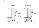
- FIG. 7 is a schematic view showing a contact state between a protective layer and water droplets in a conventional gas sensor element
- FIG. 8 is an enlarged sectional view of an essential part showing a configuration of a protective layer of a gas sensor element in Embodiment 1.
- FIG. 9 is an enlarged sectional view of an essential part for explaining the function and effect of the protective layer of the gas sensor element in Embodiment 1.
- FIG. 10 is a main part enlarged sectional view showing another example of the shape of the protective layer of the gas sensor element in the first embodiment, FIG.
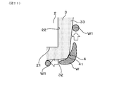
- FIG. 11 is a main part enlarged sectional view showing another example of the shape of the protective layer of the gas sensor element in Embodiment 1.
- 12 is a manufacturing process diagram of a gas sensor element in Embodiment 1
- FIG. 13 is an enlarged cross-sectional view of a main part of a gas sensor element for explaining a method of water immersion test in Test Example 1
- FIG. 14 is an enlarged view of an essential part for explaining the configuration of the protective layer of the gas sensor element in Test Example 1
- FIG. 15 is a diagram showing the relationship between L / t and the amount of dropped water droplets in Test Example 1
- FIG. 16 is an enlarged sectional view of an essential part showing a configuration of a protective layer of a gas sensor element in Embodiment 2.
- FIG. 17 is a main part enlarged cross-sectional view showing another example of the shape of the protective layer of the gas sensor element in Embodiment 2.
- FIG. 18 is a main part enlarged sectional view showing another example of the shape of the protective layer of the gas sensor element in the second embodiment
- FIG. 19 is a main part enlarged sectional view showing another example of the shape of the protective layer of the gas sensor element in the second embodiment
- FIG. 20 is a manufacturing process diagram of a gas sensor element in Embodiment 2
- FIG. 21 is an enlarged sectional view of an essential part showing a configuration of a protective layer of a gas sensor element in Embodiment 3.
- the gas sensor element 1 shown in FIGS. 1 and 2 constitutes the main part of the gas sensor S shown in FIG. 3 and the outer periphery thereof is supported by the cylindrical housing H in a state of being inserted into the cylindrical insulator I. .
- the gas sensor S can be applied to, for example, an exhaust gas purification system of an automobile engine, and the gas sensor element 1 detects a specific gas concentration in the exhaust gas which is a measurement gas. Specifically, it can be used for an oxygen sensor that detects an oxygen concentration, an air-fuel ratio sensor that detects an air-fuel ratio (that is, A / F) based on the oxygen concentration, or the like.
- the gas sensor element 1 is provided with a long plate-like element body 2 and a porous protective layer 3 for protecting the surface of the element body 2.
- the element body 2 is held on the inside with the axial direction of the insulator I as the longitudinal direction (ie, the vertical direction in FIG. 2) X, and the tip surface 21 side which is one end face of the longitudinal direction X (for example, FIG. A gas detection unit 20 is provided at the end of the reference).
- the element body 2 can be in the shape of a rectangular parallelepiped having a rectangular cross section.
- the protective layer 3 is provided so as to cover the outer periphery of the end portion on the tip surface 21 side of the element body 2 which protrudes from the insulator I in a layered manner.
- the outer surface 31 of the protective layer 3 that faces the element corner 23 where the two surfaces intersect in a cross section including two adjacent surfaces among the end surface 21 and the end surface 21 of the element body 2.
- a corner 4 of effective length L is provided on the outer surface 31 where it intersects 33.
- the corner 4 of the protective layer 3 is located on the extension of the line A which bisects the element corner 23 of the element body 2.
- the gas sensor S is attached to, for example, an exhaust gas pipe and used in an environment exposed to the exhaust gas as the gas to be measured, and the protective layer 3 covering the element body 2 of the gas sensor element 1 contains condensed water or poisoning contained in the exhaust gas.
- the element body 2 is protected from the substance.
- the shape and size of the corner 4 of the protective layer 3 are appropriately set, and in particular, with respect to the effective length L of the corner 4, the water droplets W contained in the exhaust gas in the use environment (see, eg, FIG. 5)
- the ratio D / L of the assumed diameter D to be 1.5 or more, it is possible to break the water droplet W in contact and improve the water resistance.
- the effective length L is L> 0.
- the corner 4 has a water droplet contact surface 41 on the surface located outside the element corner 23.
- the water droplet contact surface 41 is a surface including an intersection c of an extension line of a line A bisecting the element corner 23 and the outer surface 31 of the protective layer 3 in a cross section including two adjacent surfaces of the element body 2. And break the water droplet W in contact with the vicinity of the intersection point c.
- the effective length L of the corner 4 can be the distance between both ends of the water droplet contact surface 41 in a cross section including two surfaces.
- the gas sensor S has a cylindrical housing H whose axial direction is the longitudinal direction X of the gas sensor element 1 (that is, the vertical direction in the figure), and the gas sensor element 1 is inserted and held in the housing H .
- one end side of the gas sensor element 1 having the gas detection unit 20 is a tip end side (that is, the lower end side in the drawing), and the opposite side is a base end side (that is, the upper end side in the drawing).
- An element cover S1 as a cover body is attached to the front end side of the housing H, and the front end portion of the gas sensor element 1 protrudes from the housing H and is accommodated in the element cover S1.
- the atmosphere side cover S2 is attached to the base end side (that is, the upper end side in the figure) of the housing H, and the base end of the gas sensor element 1 protrudes from the housing H and is accommodated in the atmosphere side cover S2. Be done.
- the element cover S ⁇ b> 1 has a cylindrical shape with an inner and outer double bottom, and is disposed so as to surround the periphery of the tip of the gas sensor element 1.
- the inner cover S11 and the outer cover S12 of the element cover S1 are provided with through holes S13 and S14 respectively serving as a lead-in / out hole of exhaust gas on the side surface and the bottom surface, respectively.
- the cylindrical atmosphere side cover S2 is provided with a through hole S21 which is opened on the outer peripheral side surface and becomes an atmosphere hole, and takes in the atmosphere inside.
- the outer periphery of the middle portion is held inside the cylindrical insulator I housed in the housing H, and the sealing glass I 1 is provided between the opening on the base end side of the insulator I and the gas sensor element 1. It is filled.
- the insulator I an intermediate large diameter portion is supported on the stepped portion of the housing H, talc powder I2 is filled between the outer peripheral surface of the insulator I and the inner peripheral surface of the housing H, and the cylindrical insulating member I3 is interposed. It is fixed by caulking the proximal end thin portion of the housing H.
- the gas sensor element 1 incorporates the heater unit 5 on the side of the front end surface 21 of the element body 2.
- the heater unit 5 includes a heater electrode 51 and a lead unit 52 for energization, and generates heat from the heater electrode 51 by energization from the outside to activate a portion corresponding to the gas detection unit 20 of the element main body 2. Can be heated up.
- the gas detection unit 20 of the gas sensor element 1 is provided, for example, on the surface of the solid electrolyte body 11 of oxide ion conductivity and the solid electrolyte body 11 on the measured gas side.
- a measurement gas side electrode 12 into which a measurement gas is introduced and a reference gas side electrode 13 provided on the surface on the reference gas side of the solid electrolyte body 11 and facing the reference gas chamber 10 are provided.
- the dense shielding layer 15 is stacked on the surface opposite to the solid electrolyte body 11, and the gas introduction port 16 exposed on the outer surface of the side portion is formed.
- the heater substrate 53 is stacked on the surface opposite to the solid electrolyte body 11, and the heater electrode 51 is embedded in the heater substrate 53,
- the heater unit 5 is configured.
- the heater substrate 53, the reference gas chamber formation layer 17, the solid electrolyte body 11, the porous diffusion resistance layer 14, and the shielding layer 15 are sequentially stacked to form the element body 2.
- the element main body 2 has a rectangular cross-sectional shape, it may have a polygonal cross-sectional shape.
- a hexagonal or octagonal surface may be used as an inclined surface that is inclined with respect to the stacking direction.
- the cross-sectional shape of Also in such a case, the corner 4 of the protective layer 3 is formed corresponding to each element corner 23.
- the protective layer 3 is made of a porous body in which a large number of pores are present between the ceramic particles, and is adjusted to have a desired porosity.
- the ceramic particles are made of, for example, an insulating ceramic such as alumina.
- the solid electrolyte body 11 is made of, for example, a zirconia-based solid electrolyte, and the heater substrate 18, the reference gas chamber forming layer 17, the solid electrolyte body 11, the porous diffusion resistance layer 14, and the shielding layer 15 are, for example, alumina, spinel, etc. Made of insulating ceramics.
- the exhaust gas is introduced to the measurement gas side electrode 12 through the porous diffusion resistance layer 14, and between the reference gas side electrode 13 on the side of the reference gas chamber 10 where the atmosphere is introduced.
- the sensor output exhibits a limiting current characteristic according to the oxygen concentration. Using this, an air-fuel ratio signal corresponding to the oxygen concentration in the exhaust gas can be obtained.
- the protective layer 3 covers the outer periphery of the end on the tip surface 21 side of the element body 2 and is formed with a substantially uniform thickness. That is, the protective layer 3 covers the entire tip surface 21 in layers, and covers the ends of the plurality of side surfaces 22 connected thereto in layers, and an end surface 32 located on the tip side of the tip surface 21; The corner 4 is formed at a position where the side surface 33 located on the side of the plurality of side surfaces 22 is connected.
- the outer shape of the protective layer 3 is approximately similar to the outer shape of the element body 2, and the protective layer 3 is larger than the element body 2 by the thickness thereof.
- FIG. 4 with respect to the end face 32 of the protective layer 3 corresponding to the front end face 21 of the element main body 2 and a plurality of side faces 33 connected to the end face 32, arbitrary adjacent ones of the end face 32 and the side face 33 A corner 4 is formed between the two mating surfaces.
- the rectangular end face 32 of the protective layer 3 it is orthogonal to the longitudinal direction X along the connection portion between the four sides of the outer peripheral edge and the side edges of the four side surfaces 33 connected to these four sides. In the direction, each has a corner 4 extending in a straight line.
- the rectangular side surfaces 33 of the protective layer 3 have the corner portions 4 linearly extending in the longitudinal direction X along the connecting portions of the side edge portions of the two adjacent side surfaces.
- the water droplet W is made to be small by making the water droplet contact surface 41 of the corner 4 sufficiently smaller than the water droplet W reaching the surface of the gas sensor element 1. It can be split at four. Specifically, when the ratio D / L of the assumed diameter D of the water droplet W to the effective length L of the corner 4 (for example, the distance between both ends of the water droplet contact surface 41) is 1.5 or more An effect is obtained. As a result, the water droplet W1 split from the water droplet W moves to the outside of the water droplet contact surface 41, and it is suppressed that the whole of the water droplet W is absorbed in the corner 4. Therefore, the water stress can be significantly reduced, and the element corner 23 which is the weakest against water can be protected and the effect of preventing the element cracking can be obtained.
- the entire outer surface of the protective layer 30 is curved.
- the contact area with the water droplet W reaching the outer surface of the protective layer 30 becomes large, and not only the water droplet W is easily absorbed, but also the layer thickness becomes thin at the portion corresponding to the element corner 23. Therefore, as shown in the left drawing of FIG. 7, when the diameter of the water droplet W attached to the protective layer 30 is small, even if the entire amount is absorbed, the element body 2 is not reached.
- the diameter of the water droplet W becomes larger, the absorbed water droplet W easily reaches the element corner 23 having a thin layer thickness.
- the heater portion 5 of the gas sensor element 1 shown in FIG. 4 is energized to heat up to the activation temperature of the gas detection portion 20, and the surface temperature of the protective layer 3 is, for example, 400.degree. It has become ° C.
- the surface temperature of the protective layer 3 is, for example, 400.degree. It has become ° C.
- the gas sensor element 1 covers the outside of the element corner 23 with the protective layer 3 having the corner 4, and preferably, on the extension of the line A bisecting the element corner 23, the corner 4 A drop contact surface 41 is arranged to break up the drop W.
- the water droplet contact surface 41 may have a size corresponding to the assumed water droplet W, and by being arranged corresponding to the element corner 23 of the element main body 2, the element corner 23 can be protected with certainty.
- a protective layer 3 can be manufactured by a molding method as described later.
- the corner 4 of the protective layer 3 can have, for example, a C-plane shape.
- the corner 4 is on the extension of the line A that bisects the element corner 23 located inside the corner 4 and is substantially planar including the intersection point c of the extension of the line A and the outer surface 31 of the protective layer 3
- the surface of the water droplet contact surface 41 is.
- the water droplet contact surface 41 has a shape change point a which is bent in a direction toward the side surface 22 of the element body 2 with the intersection point c as a reference, and has a shape change point b which is bent in a direction toward the tip surface 21 side. doing.
- the shape change points a and b become points at both ends of the water droplet contact surface 41 in the vertical cross section shown in FIG. 8, and the linear distance between the shape change points a and b contacts the corner 4 and the water droplet W It becomes the effective length L of the time.
- the effective length L becomes smaller and the corner 4 becomes smaller.
- the intersection point c may coincide with the shape change point a or the shape change point b, or may be at a position substantially coinciding with both of the shape change points a and b. In that case, the effective length L of the corner 4 is extremely small.
- the outer surface 31 of the protective layer 3 may have a shape having a plurality of shape change points from the intersection point c toward the end surface 32 side or the side surface 33 side of the protective layer 3.
- the water droplet contact surface 41 is defined by the shape change points a and b closest to the intersection point c.
- bending in the direction toward the distal end surface 21 or the side surface 22 is preferably when the bending angle is about 150 ° or less at a bending portion to which a plurality of flat surfaces are connected as shown in FIG. And the bent portion can be taken as a shape change point.
- the outer surface 31 of the end face 32 or the side face 33 of the protective layer 3 may not necessarily be formed of only a flat surface.
- FIG. 8 illustrates one cross section of the corner 4 where the end face 32 of the protective layer 3 and one side surface 33 intersect
- the same water droplet contact surface is also seen in different cross sections of the continuous corner 4. 41 are formed.
- the water droplet contact surface 41 of effective length L is similarly formed also in the corner 4 where the end surface 32 and the other side surface 33 or side surfaces 33 cross.
- the effective length L of the water droplet contact surface 41 of any corner 4 is a ratio D / to the assumed diameter D of the water droplet W expected to reach the corner 4 together with the exhaust gas in the use environment.
- L is set to be 1.5 or more.
- the effective lengths L may be approximately constant or different.
- the cross-sectional shape and the effective length L of one continuous corner 4 are approximately constant, they may be partially different.
- the effect of splitting the water droplet W is obtained when the ratio D / L is 1.5 or more.
- the ratio D / L is larger than 1.5, for example, when an assumed diameter D is set, the smaller the effective length L of the corner 4 is, the smaller the contact area with the water droplet W becomes.
- the splitting effect is increased.
- the smaller the water droplet contact surface 41 becomes with respect to the size of the water droplet W the amount of water droplets absorbed in the corner 4 decreases, and the water droplet W1 which is split and becomes smaller in diameter becomes Since the water droplet contact surface 41 is quickly separated, the amount of water can be greatly reduced.
- the size of the water droplet W reaching the gas sensor element 1 is usually limited by the through holes S13 and S14 of the element cover S1 in which the gas sensor element 1 is accommodated. That is, the assumed diameter D of the water droplet W reaching the gas sensor element 1 is determined depending on the size of the hole diameter of the through holes S13 and S14 of the element cover S1 and the clearance between the inner cover S11 and the outer cover S12 It becomes larger than the minimum diameter of through-holes S13 and S14.
- the diameters of the through holes S13 and S14 tend to be large, and the assumed diameter D is also large.
- the assumed diameter D for each gas sensor S based on the predicted value or the test value of the average diameter or the maximum diameter of the water droplets W passing through the element cover S1 according to the usage environment.
- the shape of the water droplet contact surface 41 of the corner 4 can be set so as to be a predetermined ratio D / L.
- the ratio D / L is preferably 2.0 or more, and the effective length L of the corner 4 is preferably less than 1.0 mm.
- the ratio D / L is 2.0 or more by forming the corner 4 so that the effective length L is less than 1.0 mm.
- the protective layer 3 has an effective length L or a layer thickness such that a ratio L / t of the effective length L of the corner 4 to the layer thickness t of the protective layer 3 at the corner 4 is 6 or less. It is good to adjust t.
- the layer thickness t at the corner 4 is the shortest distance between the corresponding element corner 23 and the outer surface 31 of the protective layer 3, that is, the intersection point c extending the line A bisecting the element corner 23 and the element angle It is represented by the distance between the part 23.
- the ratio L / t is smaller than or equal to 6
- the layer thickness t becomes relatively large with respect to the effective length L of the corner 4, and the water droplet W absorbed in the corner 4 reaches the element corner 23.
- the effect of suppressing since the effective length L of the corner 4 is relatively smaller than the layer thickness t, the effect of splitting the water droplet W at the corner 4 is enhanced.
- the corner 4 of the protective layer 3 can also be, for example, R-shaped.
- the corner 4 is on the extension of the line A bisecting the element corner 23 located inside the corner 4 and includes the intersection c of the extension of the line A and the outer surface 31 of the protective layer 3
- the curved surface is a water droplet contact surface 41.
- the water droplet contact surface 41 has a shape change point a that changes rapidly in the direction toward the side surface 22 of the element body 2 with respect to the intersection point c, has a shape change point a, and changes in shape rapidly in the direction toward the tip surface 21 side It has point b.
- the shape change points a and b are, for example, connection points between the curved water droplet contact surface 41 and the flat end surface 32 or the side surface 33 on the outer surface 31 of the protective layer 3 as illustrated. .
- the shape change points a and b become points at both ends of the water droplet contact surface 41 in the vertical cross section shown in FIG. 10, and the linear distance between the shape change points a and b contacts the corner 4 and the water droplet W It becomes the effective length L of the time. Also in the case of the R-surface shape, the effective length L becomes smaller and the corner 4 becomes smaller as the shape change point a or the shape change point b approaches the intersection point c, as in the C surface shape. Further, the intersection point c may coincide with the shape change point a or the shape change point b, or may be at a position substantially coinciding with both of the shape change points a and b.
- the water drop contact surface 41 is defined by the close shape change points a, b.
- the corner 4 of the protective layer 3 may have a convex shape that protrudes outward beyond the end face 32 or the side face 33.
- the corner 4 is an extension of the line A bisecting the element corner 23 located inside the corner 4 and can be defined in the same manner.
- a planar surface including the intersection point c of the extension of the line A and the outer surface 31 of the protective layer 3 is the water droplet contact surface 41.
- the water droplet contact surface 41 has a shape change point a which is bent in a direction toward the side surface 22 of the element body 2 with the intersection point c as a reference, and has a shape change point b which is bent in a direction toward the tip surface 21 side. doing.
- the shape change points a and b become points at both ends of the water droplet contact surface 41 in the vertical cross section shown in FIG. 11, and the linear distance between the shape change points a and b contacts the corner 4 and the water droplet W It becomes the effective length L of the time.
- the effective length L becomes smaller and the corner 4 becomes smaller.
- the intersection point c may coincide with the shape change point a or the shape change point b, or may be at a position substantially coinciding with both of the shape change points a and b.
- the outer surface 31 of the protective layer 3 may have a shape having a plurality of shape change points from the intersection point c toward the end surface 32 side or the side surface 33 side of the protective layer 3.
- the corner 4 of the illustrated convex shape further includes a shape change point d which is bent inward in the direction from the shape change point a to the side surface 33.
- the water drop contact surface 41 is similarly defined by the shape change points a and b closest to the intersection point c.
- the water droplet contact surface 41 is formed such that the ratio D / L of the assumed diameter D to the effective length L of the water droplet W is 1.5 or more.
- the same effect can be obtained by setting the effective length L and the layer thickness t with respect to the assumed diameter D so that the ratio L / t to the layer thickness t of the protective layer 3 is 6 or less. can get.
- a molding method can be employed.
- the slurry 200 containing the ceramic material constituting the protective layer 3 is injected into the container-like mold 100.
- the forming die 100 is, for example, composed of two dies 101 and 102 having a split structure, and the hollow portion 103 formed in the abutment portion of the two dies 101 and 102 has a shape corresponding to the outer shape of the protective layer 3 ing.
- the bottom inner peripheral edge portions of the two molds 101 and 102 are formed in a C-shape, and the corner portions 104 are formed to be inclined inward from the inner side surface toward the bottom surface.
- the slurry 200 is a protective layer forming material configured by adding an inorganic binder, a coagulant and the like to a ceramic material to be the protective layer 3.
- the element body 2 is inserted from the upper opening of the hollow portion into the mold 100 into which the slurry 200 has been injected, and is positioned and held by a jig not shown. Temporarily cure.
- the two molds 101 and 102 are opened, the element body 2 covered with the temporarily cured slurry 200 is taken out, and baking is performed (for example, 1000 ° C.). Form.
- a method of adding a curing agent such as a UV resin or a thermosetting resin to the slurry 200 and performing UV irradiation or heat curing can be used.
- a curing agent such as a UV resin or a thermosetting resin
- the corner 4 having a desired shape can be obtained.
- the protective layer 3 can be formed with high accuracy.
- Test Example 1 The influence of the shape of the corner 4 of the protective layer 3 on the water resistance was evaluated for the sample of the gas sensor element 1 manufactured by the method described above.
- the gas sensor element 1 makes the corner 4 of the protective layer 3 C-shaped (for example, see FIG. 9), and manufactures a plurality of samples having different effective lengths L, and went.
- the ratio D / L of the effective length L of the corner 4 to the assumed diameter D of the water droplet W was changed by combining with two types of water droplet amounts corresponding to the assumed diameter D of the water droplet W.
- the gas sensor element 1 is fixed by a jig (not shown) so that the corner 4 of the protective layer 3 is positioned at the upper end, and the heater 5 is energized to perform predetermined control.
- the control temperature by the heater 5, the layer thickness of the protective layer 3 of the gas sensor element 1, the longitudinal length of the protective layer 3, the bending angle at both ends of the water droplet contact surface 41 of the corner 4, the dimensions of the element body 2 are as follows.
- Layer thickness of protective layer 3 0.15 mm
- Longitudinal length of protective layer 3 10 mm
- Bend angle of corner 4 150 °
- Control temperature 750 ° C Longitudinal length of element body 2: about 50 mm
- the drop amount of the water droplet W (that is, the water droplet amount) is 2 ⁇ L or 3 ⁇ L, and the presence or absence of the water droplet W breaks when the effective length L of the corner 4 is changed in the range of 0.82 mm to 1.22 mm.
- the water droplet diameter corresponding to the water droplet amount is regarded as the assumed diameter D
- the ratio D / L is calculated
- the relationship with the division of the water droplet W is investigated, and the results are shown in Table 1 (ie, Example 1 to 3, Comparative Examples 1 to 2). In the determination, no division was made when all the water droplets W were absorbed by the protective layer 3, and division was made when some of the water droplets W were not absorbed by the protective layer 3.
- Example 1-3 and Comparative Example 1-2 the IL change rate of the gas sensor element 1 before and after the water test was examined, and the results are also shown in Table 1.
- the rate of change of IL measures the sensor current IL output from the gas detection unit 20 using a test gas having a predetermined gas composition from the gas sensor element 1, and calculates the rate of change of the sensor current IL before and after the water test. It was evaluated as follows. IL change rate more than 10%: not acceptable IL change rate more than 5% but not more than 10%: acceptable IL change rate less than 5%: good
- the IL change rate is for determining the degree of element cracking due to water immersion .
- the amount of gas inflow to the gas detection unit 20 increases and the sensor current IL increases.
- the measurement variation of the sensor current IL is about 10% at the maximum.
- the case where the IL change rate exceeds 10% is regarded as not possible.
- the case where the IL change rate is 5% or less is considered as good, and the case where it is within the range of measurement variation is considered as possible.
- Example 1 in which the effective length L of the corner 4 is 1.0 mm or more, the IL change rate is acceptable, and in Examples 2 and 3 in which the effective length L of the corner 4 is less than 1.0 mm, The rate of change became good.
- the ratio D / L is 1.5 or more, the water droplet W can be split at the corner 4 and absorption of the water droplet W is suppressed even when the water droplet amount is relatively large, and the element is broken. It turns out that it is possible to prevent.
- the effective length L of the corner 4 is less than 1.0 mm, it is possible to set the ratio D / L to around 2.0 or more, and promote the splitting of the water droplet W.
- the water stress can be reduced and the IL change rate can be kept good.
- the wet test was performed in the same manner as in Test Example 1 above, and the drop amount of the water droplet W was 3 ⁇ L, and the presence or absence of element breakage was determined from the IL change rate. Furthermore, if it is determined that there is no element breakage, the dripping amount is gradually increased, and the water deposition test is repeated until it is determined that the element breakage has occurred, that is, until the IL change rate becomes unacceptable. The results are shown in FIG.
- the effective length L of the corner 4 and the layer thickness t of the protective layer 3 at the corner 4 may be adjusted so that the ratio L / t is 6 or less.
- the ratio L / t is 6 or less.
- the protective layer 3 has a rectangular outer shape that is substantially similar to the rectangular main body 2.
- the two opposing surfaces may not necessarily be arranged in parallel.
- the end face 32 or the side face 33 may be inclined with respect to the tip end face 21 or the side face 22 of the element main body 2, and the angle between the end face 32 and the side face 33 is not perpendicular.
- the basic structure of the gas sensor element 1 and the gas sensor S in the present embodiment is the same as that of the first embodiment, and the description will be omitted.
- symbol used in Embodiment 2 or subsequent ones represents the component similar to the thing in already-appeared embodiment, etc., unless shown.
- both the end surface 32 and the side surface 33 of the protective layer 3 can be inclined with respect to the tip surface 21 and the side surface 22 of the element body 2.
- the end surface 32 and the side surface 33 of the protective layer 3 are each an inclined surface which diverges in the direction away from the corner 4 and the angle ⁇ between the end surface 32 and the side surface 33 is an obtuse angle.
- the same effect can be obtained by appropriately setting the effective length L of the corner 4 with respect to the assumed diameter D of the water droplet W.
- one of the end surface 32 and the side surface 33 may be parallel to the opposing end surface 21 or side surface 22.
- the end face 32 of the protective layer 3 is disposed in parallel with the front end face 21 of the element body 2, and the side face 33 of the protective layer 3 is an inclined face with respect to the side face 22 of the element body 2.
- the side surface 33 of the protective layer 3 is an inclined surface that diverges toward the end surface 32 so that the angle ⁇ between the end surface 32 and the side surface 33 is an acute angle.
- the water droplet W1 split at the corner 4 is easily separated from the end surface 32 or the side surface 33, and the probability of contacting the outer surface 31 of the protective layer 3 again decreases. Further, since the layer thickness of the protective layer 3 becomes thicker toward the end face 32, it is advantageous to increase the layer thickness t at the corner 4 and reduce the ratio L / t. Both the end surface 32 and the side surface 33 may be inclined surfaces which are diverged toward the corner 4 side.
- the shape of the end face 32 or the side face 33 is not limited to a flat face or an inclined face, and may be a curved face, or a shape combining a plurality of them.
- the end surface 32 in the left view of FIG. 18, in the protective layer 3, is a concave surface having a curved surface shape.
- the outer surface 31 of the side surface 33 is a concave surface having a smooth curved surface shape at an end (in the lower end in the figure) 331 on the end surface 32 side.
- the corner 4 is formed at the connecting portion of the curved end face 32 and the end 331 of the side face 33, and since it is positioned to project outward with respect to the end face 32 and the side face 33 It becomes easy to separate the dropped water droplet W1, and it becomes difficult to touch again.
- the end face 32 may be a concave surface in which a flat surface and an inclined surface are combined.
- the end portion 321 on the side surface 33 side is an inclined surface which diverges outward, and the corner 4 is formed at the connection portion with the side surface 33 which is a flat surface.
- the end face 32 may be a flat surface, and the corner 4 may be formed at the connection with the end 331 of the curved side 33.
- the two side surfaces 33 can also be curved concaves in the corner 4 formed at the connection portion with the two side surfaces 33.
- the two side surfaces 33 can also be made into the concave surface which combined the flat surface and the inclined surface.
- the corner 4 is formed at the connecting portion of the end 331 of the two side surfaces 33 which are inclined surfaces.
- the corner 4 is formed. The broken water droplets W1 are easily separated and are less likely to be touched again.
- the protective layer 3 has the same effect as long as the two surfaces connected to both sides of the corner 4 have an acute angle, even if the entire end surface 32 or side surface 33 is not inclined or concave. Is obtained. That is, a part of the end surface 32 or the side surface 33 to be the outer surface 31 of the protective layer 3 may be an inclined surface or a curved surface spreading outward toward the corner 4.
- the gas sensor element 1 having such a shape can also be manufactured, for example, by a molding method as in the first embodiment.
- the container-like mold 100 is formed of two molds 101 and 102 of a split structure and is formed at the abutment portion of the two molds 101 and 102.
- the hollow portion 103 has a shape corresponding to the outer shape of the protective layer 3.
- the inner side surface 105 of the two molds 101 and 102 is formed as an inclined surface which is diverged toward the bottom surface side, and the inner peripheral edge portion of the bottom surface is formed into a C-like shape. It has a shape of a corner 104 that is inclined toward the inside.
- the slurry 200 containing the ceramic material constituting the protective layer 3 is injected, and then, in the process shown in (2), the element body 2 is inserted into the mold 100 into which the slurry 200 is injected.
- the slurry 200 is temporarily cured by positioning and holding with a jig (not shown) or the like. Thereafter, in the step shown in (3), the two molds 101 and 102 are opened, the element body 2 covered with the temporarily cured slurry 200 is taken out, and baking is performed (for example, 1000 ° C.). It can be formed.
- the wet test is carried out in the same manner as in Test Example 2 above, the drop amount of the water droplet W is gradually increased from 3 ⁇ L, the IL change rate is calculated, and element breakage does not occur (ie, the IL change rate is 5% or less The maximum amount of water drops judged to be) was examined. The results are shown in Table 2.
- Example 4 in which the angle ⁇ between the two surfaces of the protective layer 3 is 110 ° and an obtuse angle, the effective length L of the corner 4 is reduced to about 0.9 mm, Even when the water droplet volume was as large as 3 ⁇ L (that is, the water droplet diameter: equivalent to 1.79 mm), the IL change rate could be suppressed to 5% or less. Further, in Example 5 in which the angle ⁇ is 85 ° and an acute angle, the IL change rate can be suppressed to 5% or less even when the water droplet amount is as large as 8 ⁇ L (that is, the water droplet diameter is equivalent to 2.48 mm). It can be seen that the effect of breaking up the water droplet W and reducing the amount of absorption is further enhanced. In addition, ratio D / L when the water droplet diameter in Example 3, 4 is made into the assumed diameter D becomes respectively 1.95 and 2.70.
- Embodiment 3 which concerns on a gas sensor element and a gas sensor is described with reference to FIG.
- the water resistance can be imparted to the protective layer 3 to further improve the water resistance.
- the protective layer 3 has a structure capable of generating the Leidenfrost phenomenon, and further has a hydrophobic film on the surface. It is good also as composition.
- the basic structure of the gas sensor element 1 and the gas sensor S in the present embodiment is the same as that of the first embodiment, and the description will be omitted.
- the configuration of the protective layer 3 shown in FIG. 21 is the same as that of the second embodiment shown in FIG. 16 above, and the end face 32 and the side face 33 of the protective layer 3 diverge in the direction away from the corner 4
- the angle ⁇ between the end face 32 and the side face 33 is an obtuse angle.
- a hydrophobic film can be formed by applying a heat resistant fluorocarbon resin or the like on the surface of the protective layer 3 to form the water-repellent protective layer 3.
- the layer of ceramic particles constituting the surface layer of the protective layer 3 a relatively dense layer to increase the thermal conductivity, it is possible to impart water repellency.
- the thermal conductivity is preferably in the range of, for example, 0.2 to 5 W / mK.
- Test Example 4 water repellence was imparted to the protective layer 3 of the sample of the gas sensor element 1 manufactured by the same method as that of the above-mentioned Test Example 3, and the influence on the element breakage was evaluated.
- the sample of the gas sensor element 1 has the same shape as that of the fourth embodiment in the above test example 3, and the effective length L of the corner 4 is about 0.9 mm, and the angle ⁇ between the end face 32 of the protective layer 3 and the side face 33 It was an obtuse angle of °.
- the layer thickness t of the protective layer 3 at the corner portion 4 was 0.15 mm, and a hydrophobic film was formed on the surface of the protective layer 3 by applying a heat resistant fluorocarbon resin to Example 6 .
- the wet test is carried out in the same manner as in Test Example 3 above, the drop amount of the water droplet W is gradually increased from 3 ⁇ L, the IL change rate is calculated, and element breakage does not occur (that is, the IL change rate is 5% or less) The maximum amount of water drops judged to be) was examined.
- the results are shown in Table 3.
- the effective length L of the corner 4 was about 0.9 mm, and the angle ⁇ between the end face 32 of the protective layer 3 and the side face 33 was an obtuse angle of 110 °.
- the layer thickness t of the protective layer 3 at the corner 4 was 0.15 mm.
- Example 4 in which the protective layer 3 is rendered water repellent as to Example 4 in which the angle ⁇ between the two surfaces of the protective layer 3 is obtuse, the amount of water droplets is 3 ⁇ L (that is, Even when the water droplet amount was as large as 10 ⁇ L (that is, water droplet diameter: 2.68 mm) from the water droplet diameter: 1.79 mm, the IL change rate could be suppressed to 5% or less. Thereby, it turns out that the effect which makes the water droplet W split and the amount of absorption reduces is further enhanced because the protective layer 3 has water repellency.
- the ratio D / L when the water droplet diameter is assumed to be the assumed diameter D is 2.90.
- the present disclosure is not limited to only the embodiments, and different embodiments can be configured without departing from the scope of the invention.
- the structures of the gas sensor element 1 and the gas sensor S are not limited to the structures shown in the above embodiment, and, for example, the structures of the element cover and other parts can be changed appropriately according to the application.
- the gas to be measured is not limited to the exhaust gas from the automobile engine, and the specific gas component can also be an arbitrary gas component.
Landscapes
- Chemical & Material Sciences (AREA)
- Life Sciences & Earth Sciences (AREA)
- Health & Medical Sciences (AREA)
- Physics & Mathematics (AREA)
- Chemical Kinetics & Catalysis (AREA)
- Electrochemistry (AREA)
- Molecular Biology (AREA)
- Analytical Chemistry (AREA)
- Biochemistry (AREA)
- General Health & Medical Sciences (AREA)
- General Physics & Mathematics (AREA)
- Immunology (AREA)
- Pathology (AREA)
- Measuring Oxygen Concentration In Cells (AREA)
Abstract
被測定ガス中の特定ガス成分を検出するガスセンサ素子(1)は、長手方向(X)の先端面(21)側の端部にガス検知部(20)を有する、長板状の素子本体(2)と、上記素子本体の上記一端面側の端部外周を覆って設けられる、多孔質の保護層(3)とを備えており、上記保護層は、上記一端面及び上記一端面に連なる複数の側面(22)のうち、隣り合う2つの面を含む断面において、上記2つの面が交わる素子角部(23)と対向する外表面(31)が、角部(4)を有する形状であり、上記角部は、使用環境にて被測定ガスに含まれる水滴(W)の想定直径(D)と、上記断面における上記角部の有効長(L)との比率(D/L)が、1.5以上である。
Description
本出願は、2017年8月22日に出願された日本出願番号2017-159692号に基づくもので、ここにその記載内容を援用する。
本開示は、多孔質の保護層で被覆されたガスセンサ素子及びガスセンサ素子を備えるガスセンサに関する。
自動車エンジンの排気系には、特定の排出ガスを検出するためのガスセンサが配設されており、ガスセンサの検出結果に基づく燃焼制御等を行うことで、エミッション低減を図っている。ガスセンサは、カバー体内に収容される長板状のガスセンサ素子を有し、ガスセンサ素子は、外表面に設けられた多孔質の保護層によって、水滴や被毒物質の侵入から保護されている。ガスセンサ素子は、ガス検知部が設けられる素子本体にヒータ部を内蔵して構成される。
例えば、特許文献1に記載されるように、多孔質の保護層は、通常、ディップ法等を用いて、ガスセンサ素子の素子本体を、スラリー状の保護層材料に浸漬することにより形成される。この方法で形成される保護層は、素子本体の外周全体を、概略円形又は楕円形の外形を有して取り囲み、曲面状の外表面を有している。
また、特許文献1には、保護層の撥水性を高めて、水滴の染み込みを抑制するために、保護層の熱伝導率や、熱伝導率と密度と比熱の関係を示す物性値を、所定の数値範囲に規定することが提案されている。
また、特許文献1には、保護層の撥水性を高めて、水滴の染み込みを抑制するために、保護層の熱伝導率や、熱伝導率と密度と比熱の関係を示す物性値を、所定の数値範囲に規定することが提案されている。
一方で、年々厳しくなる排出規制や燃費向上の要求に対応するために、応答性の改善が求められており、例えば、ガスセンサの搭載位置やカバー体の通孔径等を、応答性を高める方向に変更する必要が生じている。しかしながら、ガス流れを取り込みやすくするために、カバー体の通孔径を大きくすると、カバー体内に侵入する水滴径も大きくなる。その場合、耐被水性の観点からは、保護層をより厚くすることが望まれるが、保護層が厚いと、保護層内を通過するガス流れが阻害されてしまい、応答性はむしろ低下する。
しかも、特許文献1のような形状の保護層は、全体を均一に形成することが難しく、特に、素子割れが懸念される素子角部において、保護層が薄くなりやすい。また、外表面が曲面状となっているために、水滴との接触面積が大きくなり、水滴が吸収されやすい。そのために、素子角部に対応する保護層を厚くすると、全体の層厚がさらに厚くなり、応答性の向上は容易でなかった。
このように、応答性を高めるには、素子本体を覆う保護層は薄い方がよく、耐被水性を高めるには、保護層は厚い方がよいという、相反する関係にあり、応答性と耐被水性との両立が望まれている。
本開示は、より被水が生じやすい環境においても、応答性と耐被水性とを両立可能な保護層を備えるガスセンサ素子及びガスセンサを提供することを目的とする。
本開示は、より被水が生じやすい環境においても、応答性と耐被水性とを両立可能な保護層を備えるガスセンサ素子及びガスセンサを提供することを目的とする。
本開示の一態様は、
被測定ガス中の特定ガス成分を検出するガスセンサ素子(1)であって、
長手方向の一端面側の端部にガス検知部を有する、長板状の素子本体と、上記素子本体の上記一端面側の端部外周を覆って設けられる、多孔質の保護層と、を備えており、
上記保護層は、上記一端面及び上記一端面に連なる複数の側面のうち、隣り合う2つの面を含む断面において、上記2つの面が交わる素子角部と対向する外表面が、角部を有する形状であり、
上記角部は、使用環境にて被測定ガスに含まれる水滴の想定直径Dと、上記2つの面を含む断面における上記角部の有効長Lとの比率D/Lが、1.5以上である、ガスセンサ素子にある。
被測定ガス中の特定ガス成分を検出するガスセンサ素子(1)であって、
長手方向の一端面側の端部にガス検知部を有する、長板状の素子本体と、上記素子本体の上記一端面側の端部外周を覆って設けられる、多孔質の保護層と、を備えており、
上記保護層は、上記一端面及び上記一端面に連なる複数の側面のうち、隣り合う2つの面を含む断面において、上記2つの面が交わる素子角部と対向する外表面が、角部を有する形状であり、
上記角部は、使用環境にて被測定ガスに含まれる水滴の想定直径Dと、上記2つの面を含む断面における上記角部の有効長Lとの比率D/Lが、1.5以上である、ガスセンサ素子にある。
本開示の他の態様は、
上記ガスセンサ素子の外周を支持する筒状ハウジングと、上記筒状ハウジングの一端側に取付けられるカバー体とを備え、上記カバー体内に、上記保護層が設けられる上記ガスセンサ素子の一端側が収容されると共に、上記カバー体に設けられた通孔を介して、被測定ガスが上記カバー体内に導入される、ガスセンサにある。
上記ガスセンサ素子の外周を支持する筒状ハウジングと、上記筒状ハウジングの一端側に取付けられるカバー体とを備え、上記カバー体内に、上記保護層が設けられる上記ガスセンサ素子の一端側が収容されると共に、上記カバー体に設けられた通孔を介して、被測定ガスが上記カバー体内に導入される、ガスセンサにある。
上記構成のガスセンサ素子は、素子本体を覆う保護層が、素子角部に対応する角部を有しており、角部の大きさを表す所定断面における有効長と水滴の想定直径との比率が、所定値以下となっている。具体的には、この比率が1.5以上であるとき、ガスセンサ素子の表面に到達する水滴は、角部と接触して分裂することが判明した。これにより、分裂した水滴が角部から離れることで、角部に吸収される水滴量が大きく低減するので、角部の内方に位置する素子角部に水滴が到達するのを抑制できる。
このように、素子角部に対応する所定の角部を設けることで、保護層の被水ストレスが低下し、保護層の厚さを増大させることなく、耐被水性を向上させることができる。このようなガスセンサ素子を用いたガスセンサは、カバー体の通孔の配置や大きさが、ガスセンサ素子の保護のために制約されず、例えば、カバー体の通孔径を大きくして、ガス導入量を増加させることができる。したがって、被測定ガス中の特定ガス成分を応答性よく検出することが可能になる。
以上のごとく、上記態様によれば、より被水が生じやすい環境においても、応答性と耐被水性とを両立可能な保護層を備えるガスセンサ素子及びガスセンサを提供することができる。
本開示についての上記目的及びその他の目的、特徴や利点は、添付の図面を参照しながら下記の詳細な記述により、より明確になる。その図面は、
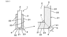
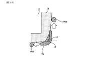
図1は、実施形態1における、ガスセンサ素子の概略図とその主要部拡大図であり、
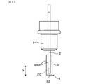
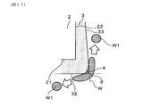
図2は、実施形態1における、ガスセンサ素子の全体概略図であり、
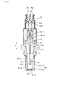
図3は、実施形態1における、ガスセンサ素子を備えるガスセンサの全体断面図であり、
図4は、実施形態1における、ガスセンサ素子の主要部構成を示す拡大斜視図であり、
図5は、実施形態1における、ガスセンサ素子の作用効果を、従来構成と比較して説明するための模式図であり、
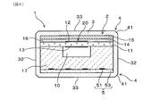
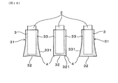
図6は、実施形態1における、ガスセンサ素子のガス検知部の構造を示す断面図であり、
図7は、従来のガスセンサ素子における、保護層と水滴との接触状態を示す模式図であり、
図8は、実施形態1における、ガスセンサ素子の保護層の構成を示す要部拡大断面図であり、
図9は、実施形態1における、ガスセンサ素子の保護層の作用効果を説明するための要部拡大断面図であり、
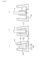
図10は、実施形態1における、ガスセンサ素子の保護層の他の形状例を示す要部拡大断面図であり、
図11は、実施形態1における、ガスセンサ素子の保護層の他の形状例を示す要部拡大断面図であり、
図12は、実施形態1における、ガスセンサ素子の製造工程図であり、
図13は、試験例1における、被水試験方法を説明するためのガスセンサ素子の要部拡大断面図であり、
図14は、試験例1における、ガスセンサ素子の保護層の構成を説明するための要部拡大図であり、
図15は、試験例1における、L/tと、滴下した水滴量との関係を示す図であり、
図16は、実施形態2における、ガスセンサ素子の保護層の構成を示す要部拡大断面図であり、
図17は、実施形態2における、ガスセンサ素子の保護層の他の形状例を示す要部拡大断面図であり、
図18は、実施形態2における、ガスセンサ素子の保護層の他の形状例を示す要部拡大断面図であり、
図19は、実施形態2における、ガスセンサ素子の保護層の他の形状例を示す要部拡大断面図であり、
図20は、実施形態2における、ガスセンサ素子の製造工程図であり、
図21は、実施形態3における、ガスセンサ素子の保護層の構成を示す要部拡大断面図である。
(実施形態1)
以下に、ガスセンサ素子及びガスセンサに係る実施形態について、図1~図6を参照して説明する。図1、図2に示されるガスセンサ素子1は、図3に示されるガスセンサSの主要部を構成し、筒状のインシュレータIに挿通された状態で、その外周が筒状ハウジングHに支持される。ガスセンサSは、例えば、自動車用エンジンの排ガス浄化システムに適用することができ、ガスセンサ素子1は、被測定ガスである排ガス中の特定ガス濃度を検出する。具体的には、酸素濃度を検出する酸素センサや、酸素濃度に基づいて空燃比(すなわち、A/F)を検出する空燃比センサ等に用いることができる。
以下に、ガスセンサ素子及びガスセンサに係る実施形態について、図1~図6を参照して説明する。図1、図2に示されるガスセンサ素子1は、図3に示されるガスセンサSの主要部を構成し、筒状のインシュレータIに挿通された状態で、その外周が筒状ハウジングHに支持される。ガスセンサSは、例えば、自動車用エンジンの排ガス浄化システムに適用することができ、ガスセンサ素子1は、被測定ガスである排ガス中の特定ガス濃度を検出する。具体的には、酸素濃度を検出する酸素センサや、酸素濃度に基づいて空燃比(すなわち、A/F)を検出する空燃比センサ等に用いることができる。
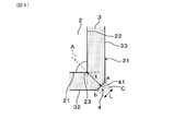
図1、図2において、ガスセンサ素子1は、長板状の素子本体2と、素子本体2の表面を保護する多孔質の保護層3と、を備えている。素子本体2は、インシュレータIの軸方向を長手方向(すなわち、図2の上下方向)Xとして、その内側に保持されており、長手方向Xの一端面である先端面21側(例えば、図1参照)の端部に、ガス検知部20を有している。素子本体2は、例えば、図4に示すように、矩形断面の直方体形状とすることができる。
保護層3は、インシュレータIから突出する、素子本体2の先端面21側の端部外周を層状に覆って設けられる。素子本体2の先端面21及び先端面21に連なる複数の側面22のうち、隣り合う2つの面を含む断面において、これら2つの面が交わる素子角部23と対向する保護層3の外表面31は、角部4を有する形状となっている。例えば、図1中に拡大して示す縦断面では、先端面21とこれに連なる1つの側面22とが交わる素子角部23が示されており、その外側において、保護層3の端面32と側面33とが交わる外表面31に、有効長Lの角部4が設けられる。好適には、保護層3の角部4は、素子本体2の素子角部23を二等分する線Aの延長線上に位置している。
ガスセンサSは、例えば、排ガス管に取り付けられて、被測定ガスである排ガスに晒される環境で使用され、ガスセンサ素子1の素子本体2を覆う保護層3は、排ガスに含まれる凝縮水や被毒物質から、素子本体2を保護している。このとき、保護層3の角部4の形状や大きさを適切に設定し、特に、角部4の有効長Lに対する、使用環境にて排ガスに含まれる水滴W(例えば、図5参照)の想定直径Dの比率D/Lが、1.5以上となるようにすることで、接触する水滴Wを分裂させて、耐被水性を向上させることが可能とになる。ここで、有効長Lは、L>0である。
具体的には、角部4は、素子角部23の外側に位置する表面に、水滴接触表面41を有する。水滴接触表面41は、素子本体2の隣り合う2つの面を含む断面において、素子角部23を二等分する線Aの延長線と保護層3の外表面31との交点cを含む表面であり、交点c近傍に接触する水滴Wを分裂させる。このとき、角部4の有効長Lは、2つの面を含む断面における、水滴接触表面41の両端間距離とすることができる。
ガスセンサ素子1に形成される保護層3及び角部4の詳細構成については、後述する。
ガスセンサ素子1に形成される保護層3及び角部4の詳細構成については、後述する。
図3において、ガスセンサSは、ガスセンサ素子1の長手方向X(すなわち、図中の上下方向)を軸方向とする筒状ハウジングHを有し、ハウジングH内にガスセンサ素子1を挿通保持している。ガスセンサSは、ガス検知部20を有するガスセンサ素子1の一端側を先端側(すなわち、図の下端側)とし、その反対側を基端側(すなわち、図の上端側)とする。ハウジングHの先端側には、カバー体としての素子カバーS1が取付けられ、ガスセンサ素子1の先端部は、ハウジングHから突出して、素子カバーS1内に収容される。同様に、ハウジングHの基端側(すなわち、図の上端側)には、大気側カバーS2が取付けられ、ガスセンサ素子1の基端部は、ハウジングHから突出して、大気側カバーS2内に収容される。
素子カバーS1は、内外二重の有底筒状で、ガスセンサ素子1の先端部の周囲を取り囲むように配置されている。素子カバーS1の内側カバーS11と外側カバーS12には、それぞれ側面及び底面に、排ガスの導出入孔となる通孔S13、S14が設けられる。通孔S13、S14を通過した排ガスは、ガスセンサ素子1の表面に到達すると、保護層3を介して、内部に取り込まれる。筒状の大気側カバーS2には、外周側面に開口し大気孔となる通孔S21が設けられ、内部に大気を取り込むようになっている。
ガスセンサ素子1は、中間部外周が、ハウジングH内に収容される筒状のインシュレータIの内側に保持され、インシュレータIの基端側開口とガスセンサ素子1との間には、封止ガラスI1が充填されている。インシュレータIは、中間大径部がハウジングHの段差部上に支持され、インシュレータIの外周面とハウジングHの内周面との間に、タルク粉末I2を充填し、筒状絶縁部材I3を介してハウジングHの基端薄肉部を加締めることで固定される。
大気側カバーS2の基端開口部には、図示しない外部のエンジン制御部に接続される複数のリード線R1、R2が絶縁保持されている。リード線R1、R2の先端側には、端子部R11、R12が設けられ、ガスセンサ素子1の基端部に設けられる、図示しない電極端子部と電気的に接続される。また、図4に示すように、ガスセンサ素子1は、素子本体2の先端面21側において、ヒータ部5を内蔵している。ヒータ部5は、ヒータ電極51と、通電用のリード部52とからなり、外部からの通電によりヒータ電極51を発熱させることで、素子本体2のガス検知部20に対応する部位を、活性温度まで加熱することができる。
図6において、ガスセンサ素子1のガス検知部20は、例えば、酸化物イオン伝導性の固体電解質体11と、固体電解質体11の被測定ガス側の面に設けられ、多孔質拡散抵抗層14を介して被測定ガスが導入される被測定ガス側電極12と、固体電解質体11の基準ガス側の面に設けられ、基準ガス室10に面する基準ガス側電極13とを有している。多孔質拡散抵抗層14には、固体電解質体11とは反対側の面に、緻密な遮蔽層15が積層されており、側部外表面に露出するガス導入口16が形成される。
基準ガス室10を形成する基準ガス室形成層17には、固体電解質体11とは反対側の面に、ヒータ基板53が積層されており、ヒータ基板53内にヒータ電極51が埋設されて、ヒータ部5を構成している。これらヒータ基板53、基準ガス室形成層17、固体電解質体11、多孔質拡散抵抗層14、遮蔽層15が順次積層されて、素子本体2が形成される。
なお、ここでは、素子本体2を、長方形断面形状としているが、多角形断面形状であってもよい。例えば、ガス検知部20側、又は、ヒータ部5側の側端部を、図示するように直角の角部とする代わりに、積層方向に対して傾斜する傾斜面として、六角形又は八角形等の断面形状としてもよい。このような場合にも、各素子角部23に対応して、保護層3の角部4がそれぞれ形成される。
保護層3は、セラミックス粒子間に多数の気孔が存在する多孔質体からなり、所望の気孔率となるように調整されている。セラミックス粒子は、例えば、アルミナ等の絶縁性セラミックスからなる。固体電解質体11は、例えば、ジルコニア系の固体電解質からなり、ヒータ基板18、基準ガス室形成層17、固体電解質体11、多孔質拡散抵抗層14、遮蔽層15は、例えば、アルミナ、スピネル等の絶縁性セラミックスからなる。
保護層3は、セラミックス粒子間に多数の気孔が存在する多孔質体からなり、所望の気孔率となるように調整されている。セラミックス粒子は、例えば、アルミナ等の絶縁性セラミックスからなる。固体電解質体11は、例えば、ジルコニア系の固体電解質からなり、ヒータ基板18、基準ガス室形成層17、固体電解質体11、多孔質拡散抵抗層14、遮蔽層15は、例えば、アルミナ、スピネル等の絶縁性セラミックスからなる。
これにより、ガス検知部20には、多孔質拡散抵抗層14を介して被測定ガス側電極12に排ガスが導入され、大気が導入される基準ガス室10側の基準ガス側電極13との間に所定電圧を印加すると、センサ出力が酸素濃度に応じた限界電流特性を示す。これを利用して、排ガス中の酸素濃度に対応する空燃比信号を得ることができる。
次に、保護層3の詳細構造について、説明する。
図1の左図において、保護層3は、素子本体2の先端面21側の端部の外周を覆って、ほぼ均一な厚さで形成されている。すなわち、保護層3は、先端面21の全体を層状に被覆すると共に、これに連なる複数の側面22の端部を層状に被覆しており、先端面21の先端側に位置する端面32と、複数の側面22の側方に位置する側面33とが接続する位置に、角部4が形成される。保護層3の外形は、素子本体2の外形と概略相似形状をなしており、保護層3は、その厚さ分だけ素子本体2よりも大きくなっている。
図1の左図において、保護層3は、素子本体2の先端面21側の端部の外周を覆って、ほぼ均一な厚さで形成されている。すなわち、保護層3は、先端面21の全体を層状に被覆すると共に、これに連なる複数の側面22の端部を層状に被覆しており、先端面21の先端側に位置する端面32と、複数の側面22の側方に位置する側面33とが接続する位置に、角部4が形成される。保護層3の外形は、素子本体2の外形と概略相似形状をなしており、保護層3は、その厚さ分だけ素子本体2よりも大きくなっている。
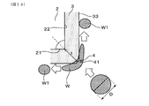
具体的には、図4において、素子本体2の先端面21に対応する、保護層3の端面32と、端面32に連なる複数の側面33について、これら端面32及び側面33のうちの任意の隣り合う2面の間に、角部4が形成される。例えば、保護層3の矩形の端面32においては、外周端縁部の4つの辺と、これら4つの辺に連なる4つの側面33の端縁部との接続部に沿って、長手方向Xと直交する方向に、それぞれ直線状に延びる角部4を有する。同様に、保護層3の矩形の側面33においては、隣り合う2つの側面の側端縁部同士の接続部に沿って、長手方向Xに、それぞれ直線状に延びる角部4を有する。
このとき、図5の左図に模式的に示すように、ガスセンサ素子1の表面に到達する水滴Wに対して、角部4の水滴接触表面41を十分小さくすることで、水滴Wを角部4において分裂させることができる。具体的には、水滴Wの想定直径Dと、角部4の有効長L(例えば、水滴接触表面41の両端間距離)との比率D/Lが、1.5以上であるときに、この効果が得られる。これにより、水滴Wから分裂した水滴W1が、水滴接触表面41の外側へ移動し、角部4に水滴Wの全量が吸収されるのを抑制する。したがって、被水ストレスを大幅に低減することができ、被水に対し最も弱い素子角部23を保護して、素子割れを防止する効果が得られる。
一方、図5の右図に比較して示すように、従来の保護層30を設けたガスセンサ素子1は、保護層30の外表面が全体に曲面状となっている。その場合、保護層30の外表面に到達する水滴Wとの接触面積が大きくなり、水滴Wが吸収されやすいだけでなく、素子角部23に対応する部位で、層厚が薄くなる。そのため、図7の左図に示すように、保護層30に付着する水滴Wの径が小さい場合には、その全量が吸収されても、素子本体2に到達することはない。ところが、図7の右図に示すように、水滴Wの径がより大きくなると、層厚が薄い素子角部23に、吸収された水滴Wが到達しやすくなる。
ガスセンサSの作動時には、上記図4に示したガスセンサ素子1のヒータ部5に通電することにより、ガス検知部20の活性温度まで加熱され、保護層3の表面温度は、例えば、400℃~600℃となっている。ここに、大きな水滴Wが付着し、外表面31から内部に染み込むと、保護層3内で熱膨張差が生じ、素子角部23に応力が集中して、素子割れを起こすおそれがある。
そこで、ガスセンサ素子1は、素子角部23の外側を、角部4を有する保護層3で覆い、好適には、素子角部23を二等分する線Aの延長線上に、角部4の水滴接触表面41を配置して、水滴Wを分裂させる。このように、水滴接触表面41は、想定される水滴Wに対応させた大きさを有していればよく、素子本体2の素子角部23に対応させて配置されることで、素子角部23を確実に保護することができる。
このような保護層3は、後述するように、型成形方法により、製作することができる。
このような保護層3は、後述するように、型成形方法により、製作することができる。
これら角部4の具体的な形状例について、図8~図10により説明する。
図8に示すように、保護層3の角部4は、例えば、C面形状とすることができる。角部4は、その内側に位置する素子角部23を二等分する線Aの延長線上にあり、線Aの延長線と保護層3の外表面31との交点cを含む、概略平面状の表面が、水滴接触表面41となっている。水滴接触表面41は、交点cを基準として、素子本体2の側面22へ向かう方向に屈曲する、形状変化点aを有すると共に、先端面21側へ向かう方向に屈曲する、形状変化点bを有している。
図8に示すように、保護層3の角部4は、例えば、C面形状とすることができる。角部4は、その内側に位置する素子角部23を二等分する線Aの延長線上にあり、線Aの延長線と保護層3の外表面31との交点cを含む、概略平面状の表面が、水滴接触表面41となっている。水滴接触表面41は、交点cを基準として、素子本体2の側面22へ向かう方向に屈曲する、形状変化点aを有すると共に、先端面21側へ向かう方向に屈曲する、形状変化点bを有している。
このとき、形状変化点a、bが、図8に示す縦断面における、水滴接触表面41の両端の点となり、形状変化点a、b間の直線距離が、角部4と水滴Wが接触するときの有効長Lとなる。形状変化点a又は形状変化点bが交点cに近づくほど有効長Lが小さくなり、角部4が小さくなる。交点cは、形状変化点a又は形状変化点bと一致してもよく、形状変化点a、bの両方とほぼ一致する位置にあってもよい。その場合には、角部4の有効長Lは極めて小さくなる。
保護層3の外表面31は、交点cから保護層3の端面32側、又は側面33側へ向かう間に、複数の形状変化点を有する形状であってもよい。その場合も、交点cに最も近い形状変化点a、bによって、水滴接触表面41が規定される。なお、先端面21又は側面22へ向かう方向に屈曲するとは、好ましくは、図8のように、複数の平坦な表面が接続する屈曲部において、その屈曲角度が150°前後ないしそれ以下であるときを言い、その屈曲部を、形状変化点とすることができる。また、保護層3の端面32又は側面33における外表面31は、必ずしも平坦な面のみで形成されていなくてもよい。
図8には、保護層3の端面32と1つの側面33とが交わる角部4について、その一断面を図示しているが、連続する角部4の異なる断面においても、同様の水滴接触表面41が形成されている。また、端面32と他の側面33、又は側面33同士が交わる角部4においても、同様に、有効長Lの水滴接触表面41が形成される。好適には、いずれの角部4についても、その水滴接触表面41の有効長Lは、使用環境にて排ガスと共に角部4に到達することが見込まれる水滴Wの想定直径Dとの比率D/Lが、1.5以上となるように設定される。保護層3の複数の角部4において、それぞれの有効長Lは、概略一定であっても異なっていてもよい。また、連続する1つの角部4について、その断面形状及び有効長Lは、概略一定であることが望ましいが、部分的に異なっていてもよい。
図9に示すように、角部4の水滴接触表面41に想定直径Dの水滴Wが衝突するとき、比率D/Lが1.5以上である場合に、水滴Wを分裂させる効果が得られる。比率D/Lが1.5より大きくなるほど、例えば、ある想定直径Dが設定されている場合に、角部4の有効長Lが小さいほど、水滴Wとの接触面積が小さくなり、水滴Wを分裂させる効果が高くなる。また、水滴Wの大きさに対して水滴接触表面41がより小さくなることで、角部4に吸収される水滴量が減少し、分裂してより小径となった水滴W1は、角部4の水滴接触表面41から速やかに離れるので、被水量を大きく低減可能となる。
ガスセンサSが配置される使用環境において、ガスセンサ素子1に到達する水滴Wの大きさは、通常、ガスセンサ素子1が収容される素子カバーS1の通孔S13、S14によって制限される。すなわち、ガスセンサ素子1に到達する水滴Wの想定直径Dは、素子カバーS1の通孔S13、S14の孔径の大きさとインナーカバーS11とアウターカバーS12とのクリアランスに依存して決定され、通常は、通孔S13、S14の最小径よりも大きくなる。また、ガスセンサSに応答性が要求される場合には、通孔S13、S14の径が大きくなる傾向にあり、想定直径Dも大きくなる。したがって、ガスセンサSごとに、使用環境に応じて、素子カバーS1を通過する水滴Wの平均径や最大径の予測値又は試験値等に基づいて、想定直径Dを設定するのがよい。また、想定直径Dを基に、所定の比率D/Lとなるように、角部4の水滴接触表面41の形状を設定することができる。
好適には、比率D/Lを2.0以上とすることが好ましく、また、角部4の有効長Lは、1.0mm未満とするのがよい。例えば、排ガス浄化システムに用いられる一般的なガスセンサSであれば、有効長Lが1.0mm未満となるように角部4を形成することで、比率D/Lを2.0以上として、想定される水滴Wを、水滴接触表面41において分裂させることができる。これにより、保護層3の内部への水滴Wの侵入を抑制して、素子角部23を保護する効果が高まり、素子割れを防止することが可能になる。
また、保護層3は、角部4の有効長Lと、その角部4における保護層3の層厚tとの比率L/tが、6以下となるように、これら有効長L又は層厚tを調整するのがよい。角部4における層厚tは、対応する素子角部23と保護層3の外表面31との最短距離、すなわち、素子角部23を二等分する線Aを延長した交点cと、素子角部23との間の距離で表される。比率L/tが6以下で、より小さくなるほど、角部4の有効長Lに対して層厚tが相対的に大きくなり、角部4に吸収される水滴Wが素子角部23に到達するのを抑制する効果が高まる。または、層厚tに対して、角部4の有効長Lが相対的に小さくなるので、角部4にて水滴Wを分裂させる効果が高まる。
図10に変形例として示すように、保護層3の角部4は、例えば、R面形状とすることもできる。この場合も、角部4は、その内側に位置する素子角部23を二等分する線Aの延長線上にあり、線Aの延長線と保護層3の外表面31との交点cを含む、曲面状の表面が、水滴接触表面41となっている。水滴接触表面41は、交点cを基準として、素子本体2の側面22へ向かう方向に形状が急変する、形状変化点aを有すると共に、先端面21側へ向かう方向に形状が急変する、形状変化点bを有している。ここで、形状変化点a、bは、例えば、図示するように、保護層3の外表面31において、曲面状の水滴接触表面41と、平面上の端面32又は側面33との接続点である。
このとき、形状変化点a、bが、図10に示す縦断面における、水滴接触表面41の両端の点となり、形状変化点a、b間の直線距離が、角部4と水滴Wが接触するときの有効長Lとなる。R面形状の場合も、C面形状と同様に、形状変化点a又は形状変化点bが交点cに近づくほど有効長Lが小さくなり、角部4が小さくなる。また、交点cは、形状変化点a又は形状変化点bと一致しても、形状変化点a、bの両方とほぼ一致する位置にあってもよい。保護層3の外表面31が、交点cから保護層3の端面32側、又は側面33側へ向かう間に、複数の形状変化点を有する形状である場合には、同様に、交点cに最も近い形状変化点a、bによって、水滴接触表面41が規定される。
あるいは、図11に他の変形例として示すように、保護層3の角部4を、端面32又は側面33よりも外側へ突出する凸形状とすることもできる。この場合も、角部4は、その内側に位置する素子角部23を二等分する線Aの延長線上にあり、同様に定義することができる。具体的には、線Aの延長線と保護層3の外表面31との交点cを含む平面状の表面が、水滴接触表面41となっている。水滴接触表面41は、交点cを基準として、素子本体2の側面22へ向かう方向に屈曲する、形状変化点aを有すると共に、先端面21側へ向かう方向に屈曲する、形状変化点bを有している。
このとき、形状変化点a、bが、図11に示す縦断面における、水滴接触表面41の両端の点となり、形状変化点a、b間の直線距離が、角部4と水滴Wが接触するときの有効長Lとなる。形状変化点a又は形状変化点bが交点cに近づくほど有効長Lが小さくなり、角部4が小さくなる。また、交点cは、形状変化点a又は形状変化点bと一致しても、形状変化点a、bの両方とほぼ一致する位置にあってもよい。
保護層3の外表面31が、交点cから保護層3の端面32側、又は側面33側へ向かう間に、複数の形状変化点を有する形状であってもよい。例えば、図示する凸形状の角部4は、形状変化点aから側面33へ向かう方向に、内方へ屈曲する形状変化点dを、さらに有している。この場合にも、同様に、交点cに最も近い形状変化点a、bによって、水滴接触表面41が規定される。
図10、図11に示す角部4においても、水滴Wの想定直径Dと有効長Lとの比率D/Lが1.5以上となるように、水滴接触表面41が形成される。好適には、保護層3の層厚tとの比率L/tが6以下となるように、想定直径Dに対して、有効長Lや層厚tが設定されることで、同様の効果が得られる。
次に、ガスセンサ素子1の製造方法について説明する。
図12に示すように、素子本体2の表面に保護層3を設ける方法として、型成形方法を採用することができる。(1)に示す工程では、まず、容器状の成形型100に、保護層3を構成するセラミックス材料を含むスラリ200を注入する。成形型100は、例えば、割り子構造の2つの型101、102からなり、2つの型101、102の衝合部に形成される中空部103が、保護層3の外形に対応する形状となっている。ここでは、2つの型101、102の底面内周縁部をC面状に形成して、内側面から底面へ向けて内向きに傾斜する角部104形状としている。
図12に示すように、素子本体2の表面に保護層3を設ける方法として、型成形方法を採用することができる。(1)に示す工程では、まず、容器状の成形型100に、保護層3を構成するセラミックス材料を含むスラリ200を注入する。成形型100は、例えば、割り子構造の2つの型101、102からなり、2つの型101、102の衝合部に形成される中空部103が、保護層3の外形に対応する形状となっている。ここでは、2つの型101、102の底面内周縁部をC面状に形成して、内側面から底面へ向けて内向きに傾斜する角部104形状としている。
スラリ200は、保護層3となるセラミックス材料に、無機バインダ、凝固剤等を添加して構成される保護層形成材料である。(2)に示す工程では、このようなスラリ200が注入された成形型100に、中空部の上部開口から、素子本体2を挿入し、図示しない治具等で位置決め保持した状態で、スラリ200を仮硬化させる。その後、(3)に示す工程において、2つの型101、102を開いて、仮硬化したスラリ200で被覆された素子本体2を取り出し、焼き付けを行って(例えば、1000℃)、保護層3を形成する。
硬化方法としては、熱乾燥による方法の他、スラリ200に、UV樹脂又は熱硬化樹脂等の硬化剤を添加して、UV照射又は加熱硬化させる方法を用いることができる。このように、型成形方法を採用する場合には、予め成形型100に、保護層3の角部4に対応する形状の角部104を設けることができるので、所望の形状の角部4を有する保護層3を、精度よく形成することができる。あるいは、C面状の角部104を有しない成形型100を用いて、保護層3を成形した後に、切削加工により、角部4を形成することも可能であり、任意の形状に加工することができる。
(試験例1)
上記した方法により製作したガスセンサ素子1のサンプルについて、保護層3の角部4の形状による耐被水性への影響を評価した。ガスセンサ素子1は、保護層3の角部4をC面形状とすると共に(例えば、図9参照)、その有効長Lを変更した複数のサンプルを製作し、それぞれについて、以下の被水試験を行った。このとき、水滴Wの想定直径Dに相当する2種類の水滴量と組み合わせることにより、角部4の有効長Lと水滴Wの想定直径Dとの比率D/Lを変更した。
上記した方法により製作したガスセンサ素子1のサンプルについて、保護層3の角部4の形状による耐被水性への影響を評価した。ガスセンサ素子1は、保護層3の角部4をC面形状とすると共に(例えば、図9参照)、その有効長Lを変更した複数のサンプルを製作し、それぞれについて、以下の被水試験を行った。このとき、水滴Wの想定直径Dに相当する2種類の水滴量と組み合わせることにより、角部4の有効長Lと水滴Wの想定直径Dとの比率D/Lを変更した。
図13に示すように、被水試験は、ガスセンサ素子1を、保護層3の角部4が上端部に位置するように図示しない治具で固定し、ヒータ部5に通電して所定の制御温度に加熱した状態で、所定量の水滴Wを、上方から角部4に滴下することにより行った。ヒータ部5による制御温度、ガスセンサ素子1の保護層3の層厚、保護層3の長手方向長、角部4の水滴接触表面41の両端における屈曲角度、素子本体2の寸法は、以下の通りとした。
保護層3の層厚:0.15mm
保護層3の長手方向長:10mm
角部4の屈曲角度:150°
制御温度:750℃
素子本体2の長手方向長:約50mm
保護層3の層厚:0.15mm
保護層3の長手方向長:10mm
角部4の屈曲角度:150°
制御温度:750℃
素子本体2の長手方向長:約50mm
評価は、水滴Wの滴下量(すなわち、水滴量)を、2μL又は3μLとし、角部4の有効長Lを0.82mm~1.22mmの範囲で変更したときの水滴Wの分裂の有無を、高速度カメラを用いて目視判定することにより行った(例えば、高速度カメラ条件:10000fps)。
このとき、水滴量に相当する水滴直径を、想定直径Dとみなして、比率D/Lを算出し、水滴Wの分裂との関係を調べて、結果を表1に示した(すなわち、実施例1~3、比較例1~2)。判定は、水滴Wの全てが保護層3に吸収された場合を、分裂無とし、水滴Wの一部が保護層3に吸収されなかった場合には、分裂有とした。
このとき、水滴量に相当する水滴直径を、想定直径Dとみなして、比率D/Lを算出し、水滴Wの分裂との関係を調べて、結果を表1に示した(すなわち、実施例1~3、比較例1~2)。判定は、水滴Wの全てが保護層3に吸収された場合を、分裂無とし、水滴Wの一部が保護層3に吸収されなかった場合には、分裂有とした。
また、実施例1-3、比較例1-2のそれぞれについて、被水試験前後のガスセンサ素子1のIL変化率を調べて、結果を表1に併記した。IL変化率は、ガスセンサ素子1を所定のガス組成を有する試験用ガスを用いて、ガス検知部20から出力されるセンサ電流ILを測定し、被水試験前後におけるセンサ電流ILの変化率を算出したものであり、以下のようにして評価した。
IL変化率10%超:不可
IL変化率5%超10%以下:可
IL変化率5%以下:良
ここで、IL変化率は、被水による素子割れの程度を判定するためのものである。素子割れが生じるとガス検知部20へのガス流入量が増加して、センサ電流ILが増加すること、ただし、センサ電流ILの測定バラツキが最大で10%程度存在すると考えられることから、これを考慮して、IL変化率が10%を超える場合を、不可とした。また、センサ電流ILの増加がほとんどない場合として、IL変化率が5%以下である場合を、良とし、測定バラツキの範囲内にある場合を、可とした。
IL変化率10%超:不可
IL変化率5%超10%以下:可
IL変化率5%以下:良
ここで、IL変化率は、被水による素子割れの程度を判定するためのものである。素子割れが生じるとガス検知部20へのガス流入量が増加して、センサ電流ILが増加すること、ただし、センサ電流ILの測定バラツキが最大で10%程度存在すると考えられることから、これを考慮して、IL変化率が10%を超える場合を、不可とした。また、センサ電流ILの増加がほとんどない場合として、IL変化率が5%以下である場合を、良とし、測定バラツキの範囲内にある場合を、可とした。

表1に明らかなように、比率D/Lが1.5未満であり、水滴Wに対して角部4の有効長Lが1.2mm以上と比較的大きい比較例1、2では、水滴Wの分裂が生じていない。また、水滴量が2μL(すなわち、D=1.57mmに相当)と少ない比較例1では、IL変化率は可であり、許容範囲内となるが、水滴量が3μL(すなわち、D=1.79mmに相当)とより多い比較例2では、IL変化率が不可となっており、素子割れが生じていると考えられる。これに対して、実施例1~3は、比率D/Lが1.5以上であり、いずれも水滴Wの分裂が確認された。また、角部4の有効長Lが1.0mm以上である実施例1は、IL変化率が可となり、角部4の有効長Lが1.0mm未満である実施例2、3は、IL変化率が良となった。
これらにより、比率D/Lが1.5以上であれば、角部4において水滴Wを分裂させることができ、水滴量が比較的多い場合でも、水滴Wの吸収を抑制して、素子割れを防止可能であることがわかる。また、好適には、角部4の有効長Lを1.0mm未満とすることで、比率D/Lを2.0前後ないしそれ以上とすることが可能であり、水滴Wの分裂を促進して、被水ストレスを低減し、IL変化率を良好に保つことができる。
(試験例2)
次に、上記試験例1と同様にして製作したガスセンサ素子1のサンプルについて、角部4の有効長Lと、角部4における保護層3の層厚tとの比率L/tを変化させて、素子割れへの影響を評価した。図14に示すように、ガスセンサ素子1のサンプルは、角部4の有効長Lが比較的小さくなるようにし(例えば、約0.9mm程度)、これに対して保護層3の層厚tを増減させることにより、これらの比率L/tを10以下の範囲で変化させた。
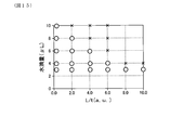
被水試験は、上記試験例1と同様にして行い、水滴Wの滴下量を3μLとして、IL変化率から素子割れの有無を判定した。さらに、素子割れが無いと判定された場合には、滴下量を徐々に増加させて、素子割れと判定されるまで、すなわち、IL変化率が不可となるまで、繰り返し被水試験を行って、結果を、図15に示した。
次に、上記試験例1と同様にして製作したガスセンサ素子1のサンプルについて、角部4の有効長Lと、角部4における保護層3の層厚tとの比率L/tを変化させて、素子割れへの影響を評価した。図14に示すように、ガスセンサ素子1のサンプルは、角部4の有効長Lが比較的小さくなるようにし(例えば、約0.9mm程度)、これに対して保護層3の層厚tを増減させることにより、これらの比率L/tを10以下の範囲で変化させた。
被水試験は、上記試験例1と同様にして行い、水滴Wの滴下量を3μLとして、IL変化率から素子割れの有無を判定した。さらに、素子割れが無いと判定された場合には、滴下量を徐々に増加させて、素子割れと判定されるまで、すなわち、IL変化率が不可となるまで、繰り返し被水試験を行って、結果を、図15に示した。
図15に明らかなように、水滴量が3μLの場合には、比率L/tが10以下の範囲であるサンプルのいずれも、素子割れは生じていない。水滴量が4μLに増加しても、比率L/tが6以下の領域では、素子割れは生じておらず、十分な耐被水性が得られることがわかる。水滴量が4μLを超えると、比率L/tが小さいほど、素子割れが生じる水滴量が多くなっている。
このように、好適には、比率L/tが6以下となるように、角部4の有効長Lと、角部4における保護層3の層厚tとを調整するとよい。このとき、角部4の有効長Lが小さいほど、保護層3への水滴Wの吸収量が小さくなり、層厚tが大きいほど、角部4に接触した水滴Wから、その内側の素子角部23への冷熱伝搬が低減される。したがって、比率L/tが小さいほど、素子角部23への応力が減少し、素子割れが抑制されて耐久性が向上する。
(実施形態2)
ガスセンサ素子及びガスセンサに係る実施形態2について、図16~図18を参照して説明する。上記実施形態1におけるガスセンサ素子1は、保護層3を、直方体形状の素子本体2と概略相似の直方体形状の外形としたが、必ずしも対向する2つの面が平行に配置されていなくてもよい。例えば、保護層3は、端面32又は側面33が、素子本体2の先端面21又は側面22に対して傾斜していてもよく、端面32と側面33とのなす角度は、直角でなくてもよい。
本形態におけるガスセンサ素子1及びガスセンサSの基本構造は、上記実施形態1と同様であり、説明を省略する。
なお、実施形態2以降において用いた符号のうち、既出の実施形態において用いた符号と同一のものは、特に示さない限り、既出の実施形態におけるものと同様の構成要素等を表す。
図16に示すように、例えば、保護層3の端面32と側面33の両方を、素子本体2の先端面21と側面22に対して傾斜面とすることができる。ここでは、保護層3の端面32と側面33を、それぞれ角部4から離れる方向へ末広がりとなる傾斜面とし、端面32と側面33のなす角度θは、鈍角となっている。この場合にも、角部4の有効長Lを、水滴Wの想定直径Dに対して適切に設定することで、同様の効果が得られる。
図17に変形例として示すように、端面32と側面33の一方を、対向する先端面21又は側面22に対して平行面とすることもできる。ここでは、保護層3の端面32を、素子本体2の先端面21と平行に配置し、保護層3の側面33を、素子本体2の側面22に対して傾斜面としている。好適には、図示するように、保護層3の側面33を、端面32側へ向けて末広がりとなる傾斜面とし、端面32と側面33とのなす角度θが鋭角になるようにするとよい。
このようにすると、角部4において分裂した水滴W1が、端面32又は側面33から離れやすくなると共に、再び保護層3の外表面31に接触する確率が低下する。また、保護層3の層厚が端面32側ほど厚くなるので、角部4における層厚tを大きくして、比率L/tを小さくするのに有利である。端面32と側面33の両方を、角部4側へ向けて末広がりとなる傾斜面とすることもできる。
図18に変形例として示すように、端面32又は側面33の形状は、平坦面や傾斜面に限らず、曲面状であってもよく、それらの複数を組み合わせた形状であってもよい。例えば、図18の左図において、保護層3は、端面32が曲面状の凹面となっている。側面33は、端面32側の端部(すなわち、図中の下端部)331において、外表面31が、滑らかな曲面状の凹面となっている。このとき、曲面状の端面32と、側面33の端部331の接続部に角部4が形成され、端面32及び側面33に対して、外方に突出して位置するので、角部4において分裂した水滴W1が離れやすく、また、再接触しにくくなる。
図18の中図に示すように、端面32を、平坦面と傾斜面を組み合わせた凹面とすることもできる。この場合は、側面33側の端部321が、外方へ向けて末広がりとなる傾斜面となっており、平坦面である側面33との接続部に角部4が形成される。また、図18に右図に示すように、端面32を平坦面とし、曲面状の側面33の端部331との接続部に角部4が形成されるようにしてもよい。
さらに、図19の左図に変形例として示すように、2つの側面33との接続部に形成される角部4についても、2つの側面33を、曲面状の凹面とすることができる。図19の右図に示すように、2つの側面33を、平坦面と傾斜面を組み合わせた凹面とすることもできる。この場合は、傾斜面である2つの側面33の端部331の接続部に、角部4が形成される。いずれにおいても、2つの側面33の間に形成される角部4、あるいは、端部331の間に形成される角部4が、2つの側面33よりも外方に突出するので、角部4において分裂した水滴W1が離れやすく、また、再接触しにくくなる。
このように、保護層3は、端面32又は側面33の全体が、傾斜面や凹面となっていなくても、角部4の両側に連なる2つの面が鋭角となっていれば、同様の効果が得られる。すなわち、保護層3の外表面31となる端面32又は側面33の一部が、角部4に向けて外方へ広がる傾斜面又は曲面となっていればよい。
このような形状のガスセンサ素子1も、上記実施形態1と同様に、例えば、型成形方法により製作することができる。
図20に示すように、(1)に示す工程において、容器状の成形型100は、割り子構造の2つの型101、102からなり、2つの型101、102の衝合部に形成される中空部103が、保護層3の外形に対応する形状となっている。ここでは、2つの型101、102の内側面105を、それぞれ底面側へ向けて末広がりとなる傾斜面に形成し、さらに、底面内周縁部をC面状に形成して、内側面から底面へ向けて内向きに傾斜する角部104形状としている。
図20に示すように、(1)に示す工程において、容器状の成形型100は、割り子構造の2つの型101、102からなり、2つの型101、102の衝合部に形成される中空部103が、保護層3の外形に対応する形状となっている。ここでは、2つの型101、102の内側面105を、それぞれ底面側へ向けて末広がりとなる傾斜面に形成し、さらに、底面内周縁部をC面状に形成して、内側面から底面へ向けて内向きに傾斜する角部104形状としている。
このような成形型100に、保護層3を構成するセラミックス材料を含むスラリ200を注入し、次いで、(2)に示す工程において、スラリ200が注入された成形型100に素子本体2を挿入し、図示しない治具等で位置決め保持して、スラリ200を仮硬化させる。その後、(3)に示す工程において、2つの型101、102を開いて、仮硬化したスラリ200で被覆された素子本体2を取り出し、焼き付けを行って(例えば、1000℃)、保護層3を形成することができる。
(試験例3)
次に、上記した方法で製作したガスセンサ素子1のサンプルについて、保護層3の端面32と側面33のなす角度θを変化させて、素子割れへの影響を評価した。ガスセンサ素子1のサンプルは、角部4の有効長Lを約0.9mmとし、保護層3の端面32と側面33の一方又は両方を傾斜させることにより、角度θを鈍角又は鋭角となるようにした(すなわち、実施例4、5)。角部4における保護層3の層厚tは、0.15mmとした。
被水試験は、上記試験例2と同様にして行い、水滴Wの滴下量を3μLから徐々に増加させてIL変化率を算出し、素子割れが生じない(すなわち、IL変化率が5%以下)と判定される最大水滴量を調べた。結果を、表2に示す。

表2に明らかなように、保護層3の2つの面のなす角度θが110°で鈍角である実施例4においても、角部4の有効長Lを約0.9mmと小さくすることで、水滴量が3μL(すなわち、水滴直径:1.79mmに相当)と多い場合でも、IL変化率を5%以下に抑制することができた。また、角度θが85°で鋭角である実施例5では、水滴量が8μL(すなわち、水滴直径:2.48mmに相当)とより多い場合でも、IL変化率を5%以下に抑制することができ、水滴Wを分裂させ、吸収量を低減する効果がさらに高まることがわかる。なお、実施例3、4における水滴直径を、想定直径Dとしたときの比率D/Lは、それぞれ、1.95、2.70となる。
(実施形態3)
ガスセンサ素子及びガスセンサに係る実施形態3について、図21を参照して説明する。上記各実施形態に示したガスセンサ素子1において、保護層3に撥水性を付与することにより、耐被水性をさらに向上させることができる。保護層3に撥水性を付与するには、例えば、上述した特許文献1に記載されるように、保護層3を、ライデンフロスト現象を発生可能な構成とする他、表面に疎水性膜を有する構成としてもよい。
本形態におけるガスセンサ素子1及びガスセンサSの基本構造は、上記実施形態1と同様であり、説明を省略する。
ガスセンサ素子及びガスセンサに係る実施形態3について、図21を参照して説明する。上記各実施形態に示したガスセンサ素子1において、保護層3に撥水性を付与することにより、耐被水性をさらに向上させることができる。保護層3に撥水性を付与するには、例えば、上述した特許文献1に記載されるように、保護層3を、ライデンフロスト現象を発生可能な構成とする他、表面に疎水性膜を有する構成としてもよい。
本形態におけるガスセンサ素子1及びガスセンサSの基本構造は、上記実施形態1と同様であり、説明を省略する。
具体的には、図21に示す保護層3の構成は、上記図16に示した実施形態2と同様であり、保護層3の端面32と側面33は、それぞれ角部4から離れる方向へ末広がりとなる傾斜面となっており、端面32と側面33のなす角度θは、鈍角である。このような構成において、例えば、保護層3の表面に、耐熱性フッ素樹脂等を塗布することにより疎水性膜を形成し、撥水性の保護層3とすることができる。あるいは、保護層3の表層を構成するセラミックス粒子の層を、比較的緻密な層として熱伝導率を高めることで、撥水性を付与することができる。熱伝導率は、例えば、0.2~5W/mKの範囲にあることが望ましく、熱伝導率を上げることで、水滴Wに対する熱流束が増加し、熱沸騰による膜を形成してライデンフロスト現象を発生可能となる。
このように、保護層3が撥水性を有することにより、水滴Wが角部4に衝突する際に、水滴接触表面41に固着する力が弱くなり、水滴Wの速度が維持されるため、より液切れしやすくなる。したがって、保護層3の角部4において水滴Wが内部に吸収されるのを抑制すると共に、分裂した水滴W1が、外表面31に再接触しても吸収されにくいので、耐被水性がより向上する。
(試験例4)
次に、上記試験例3と同様の方法で製作したガスセンサ素子1のサンプルについて、保護層3に撥水性を付与して、素子割れへの影響を評価した。ガスセンサ素子1のサンプルは、上記試験例3における実施例4と同様の形状であり、角部4の有効長Lを約0.9mm、保護層3の端面32と側面33のなす角度θを110°の鈍角とした。角部4における保護層3の層厚tは、0.15mmとし、さらに、その保護層3の表面に、耐熱性フッ素樹脂を塗布することにより疎水性膜を形成して、実施例6とした。
被水試験は、上記試験例3と同様にして行い、水滴Wの滴下量を3μLから徐々に増加させてIL変化率を算出し、素子割れが生じない(すなわち、IL変化率が5%以下)と判定される最大水滴量を調べた。結果を、表3に示す。
角部4の有効長Lを約0.9mm、保護層3の端面32と側面33のなす角度θを110°の鈍角とした。角部4における保護層3の層厚tは、0.15mmとした。

表3に明らかなように、保護層3の2つの面のなす角度θが鈍角である実施例4について、さらに、保護層3に撥水性を付与した実施例6では、水滴量が3μL(すなわち、水滴直径:1.79mmに相当)から、10μL(すなわち、水滴直径:2.68mmに相当)とより多い水滴量においても、IL変化率を5%以下に抑制することができた。これにより、保護層3が撥水性を有することで、水滴Wを分裂させ、吸収量を低減する効果がさらに高まることがわかる。なお、この水滴直径を、想定直径Dとしたときの比率D/Lは、2.90となる。
なお、本開示は、各実施形態のみに限定されるものではなく、その要旨を逸脱しない範囲においてさらに異なる実施形態を構成することが可能である。また、ガスセンサ素子1及びガスセンサSの構造は、上記実施形態に示した構造に限らず、例えば、素子カバーその他各部の構成は、用途に応じて適宜変更することができる。また、被測定ガスは自動車エンジンからの排ガスに限るものではなく、特定ガス成分も任意のガス成分とすることができる。
Claims (11)
- 被測定ガス中の特定ガス成分を検出するガスセンサ素子(1)であって、
長手方向(X)の一端面(21)側の端部にガス検知部(20)を有する、長板状の素子本体(2)と、上記素子本体の上記一端面側の端部外周を覆って設けられる、多孔質の保護層(3)と、を備えており、
上記保護層は、上記一端面及び上記一端面に連なる複数の側面(22)のうち、隣り合う2つの面を含む断面において、上記2つの面が交わる素子角部(23)と対向する外表面(31)が、角部(4)を有する形状であり、
上記角部は、使用環境にて被測定ガスに含まれる水滴(W)の想定直径(D)と、上記2つの面を含む断面における上記角部の有効長(L)との比率(D/L)が、1.5以上である、ガスセンサ素子。 - 上記角部は、上記素子角部を二等分する線(A)の延長線上に位置している、請求項1に記載のガスセンサ素子。
- 上記角部は、上記素子角部を二等分する線(A)の延長線と、上記保護層の外表面(31)との交点(c)を含む水滴接触表面(41)を有しており、
上記角部の有効長は、上記2つの面を含む断面における上記水滴接触表面の両端間距離である、請求項1又は2に記載のガスセンサ素子。 - 上記水滴接触表面は、上記交点を基準として、上記2つの面のそれぞれへ向かう方向に、形状変化点(a、b)を有しており、上記形状変化点にて上記水滴接触表面の両端が規定される、請求項3に記載のガスセンサ素子。
- 上記水滴接触表面は、平面状又は曲面状である、請求項3又は4に記載のガスセンサ素子。
- 上記角部の有効長は、1.0mm未満である、請求項1~5のいずれか1項に記載のガスセンサ素子。
- 上記角部の有効長と、上記角部における上記保護層の層厚(t)との比率(L/t)が、6以下である、請求項1~6のいずれか1項に記載のガスセンサ素子。
- 上記角部は、上記2つの面に対向する上記保護層の2つの面(32、33)の少なくとも一方より外方に突出している、請求項1~7のいずれか1項に記載のガスセンサ素子。
- 上記2つの面を含む断面において、上記角部の両側に連なる上記外表面の2つの面(32、33、321、331)のなす角度が鋭角である、請求項1~8のいずれか1項に記載のガスセンサ素子。
- 上記保護層は、撥水性を有する、請求項1~9のいずれか1項に記載のガスセンサ素子。
- 請求項1~10のいずれか1項に記載のガスセンサ素子を備えるガスセンサ(S)であって、
上記ガスセンサ素子の外周を支持する筒状ハウジング(H)と、上記筒状ハウジングの一端側に取付けられるカバー体(S1)とを備え、上記カバー体内に、上記保護層が設けられる上記ガスセンサ素子の一端側が収容されると共に、上記カバー体に設けられた通孔(S13、S14)を介して、被測定ガスが上記カバー体内に導入される、ガスセンサ。
Priority Applications (3)
| Application Number | Priority Date | Filing Date | Title |
|---|---|---|---|
| DE112018004731.8T DE112018004731T5 (de) | 2017-08-22 | 2018-08-21 | Gassensorelement und Gassensor |
| CN201880053981.2A CN111051870B (zh) | 2017-08-22 | 2018-08-21 | 气体传感器元件及气体传感器 |
| US16/786,082 US11714062B2 (en) | 2017-08-22 | 2020-02-10 | Gas sensor element and gas sensor |
Applications Claiming Priority (2)
| Application Number | Priority Date | Filing Date | Title |
|---|---|---|---|
| JP2017-159692 | 2017-08-22 | ||
| JP2017159692A JP6708184B2 (ja) | 2017-08-22 | 2017-08-22 | ガスセンサ素子及びガスセンサ |
Related Child Applications (1)
| Application Number | Title | Priority Date | Filing Date |
|---|---|---|---|
| US16/786,082 Continuation US11714062B2 (en) | 2017-08-22 | 2020-02-10 | Gas sensor element and gas sensor |
Publications (1)
| Publication Number | Publication Date |
|---|---|
| WO2019039455A1 true WO2019039455A1 (ja) | 2019-02-28 |
Family
ID=65439330
Family Applications (1)
| Application Number | Title | Priority Date | Filing Date |
|---|---|---|---|
| PCT/JP2018/030770 WO2019039455A1 (ja) | 2017-08-22 | 2018-08-21 | ガスセンサ素子及びガスセンサ |
Country Status (5)
| Country | Link |
|---|---|
| US (1) | US11714062B2 (ja) |
| JP (1) | JP6708184B2 (ja) |
| CN (1) | CN111051870B (ja) |
| DE (1) | DE112018004731T5 (ja) |
| WO (1) | WO2019039455A1 (ja) |
Cited By (1)
| Publication number | Priority date | Publication date | Assignee | Title |
|---|---|---|---|---|
| US20210199617A1 (en) * | 2019-12-26 | 2021-07-01 | Ngk Insulators, Ltd. | Sensor element for gas sensor |
Families Citing this family (2)
| Publication number | Priority date | Publication date | Assignee | Title |
|---|---|---|---|---|
| JP7195996B2 (ja) * | 2019-03-29 | 2022-12-26 | 日本碍子株式会社 | ガスセンサのセンサ素子 |
| JP7486123B2 (ja) * | 2020-07-02 | 2024-05-17 | パナソニックIpマネジメント株式会社 | ガスセンサ装置 |
Citations (3)
| Publication number | Priority date | Publication date | Assignee | Title |
|---|---|---|---|---|
| JP2012093330A (ja) * | 2010-09-27 | 2012-05-17 | Denso Corp | ガスセンサ素子及びガスセンサ |
| JP2012247293A (ja) * | 2011-05-27 | 2012-12-13 | Denso Corp | ガスセンサ素子及びその製造方法、並びにガスセンサ |
| JP2016095287A (ja) * | 2014-03-28 | 2016-05-26 | 日本碍子株式会社 | ガスセンサの製造方法及びガスセンサ |
Family Cites Families (12)
| Publication number | Priority date | Publication date | Assignee | Title |
|---|---|---|---|---|
| JP2007206082A (ja) * | 2002-02-28 | 2007-08-16 | Ngk Spark Plug Co Ltd | セラミックヒータ、積層型ガスセンサ素子及びその製造方法、並びに積層型ガスセンサ素子を備えるガスセンサ |
| US8168053B2 (en) * | 2006-01-23 | 2012-05-01 | Denso Corporation | Gas sensing member used for gas sensor and method of manufacturing the member |
| JP2008058297A (ja) * | 2006-08-04 | 2008-03-13 | Ngk Spark Plug Co Ltd | ガスセンサ |
| JP5344675B2 (ja) * | 2007-10-17 | 2013-11-20 | 日本特殊陶業株式会社 | ガスセンサ |
| JP4996527B2 (ja) * | 2008-04-14 | 2012-08-08 | 日本特殊陶業株式会社 | 積層型ガスセンサ素子及びガスセンサ |
| JP4762338B2 (ja) * | 2008-12-22 | 2011-08-31 | 株式会社日本自動車部品総合研究所 | ガスセンサ素子及びこれを備えたガスセンサ |
| JP5560296B2 (ja) * | 2012-03-06 | 2014-07-23 | 日本特殊陶業株式会社 | ガスセンサ |
| JP6530620B2 (ja) * | 2014-03-28 | 2019-06-12 | 日本碍子株式会社 | 膜接合構造体の製法 |
| JP6573767B2 (ja) | 2014-03-28 | 2019-09-11 | 日本碍子株式会社 | 膜接合構造体の製法 |
| JP6475074B2 (ja) | 2014-07-18 | 2019-02-27 | トヨタ自動車株式会社 | ガスセンサ素子 |
| JP6477022B2 (ja) | 2015-03-02 | 2019-03-06 | 株式会社デンソー | ガスセンサ素子の製造方法 |
| JP2017159692A (ja) | 2016-03-07 | 2017-09-14 | トヨタ自動車株式会社 | 車両用入力装置 |
-
2017
- 2017-08-22 JP JP2017159692A patent/JP6708184B2/ja active Active
-
2018
- 2018-08-21 CN CN201880053981.2A patent/CN111051870B/zh active Active
- 2018-08-21 WO PCT/JP2018/030770 patent/WO2019039455A1/ja active Application Filing
- 2018-08-21 DE DE112018004731.8T patent/DE112018004731T5/de active Pending
-
2020
- 2020-02-10 US US16/786,082 patent/US11714062B2/en active Active
Patent Citations (3)
| Publication number | Priority date | Publication date | Assignee | Title |
|---|---|---|---|---|
| JP2012093330A (ja) * | 2010-09-27 | 2012-05-17 | Denso Corp | ガスセンサ素子及びガスセンサ |
| JP2012247293A (ja) * | 2011-05-27 | 2012-12-13 | Denso Corp | ガスセンサ素子及びその製造方法、並びにガスセンサ |
| JP2016095287A (ja) * | 2014-03-28 | 2016-05-26 | 日本碍子株式会社 | ガスセンサの製造方法及びガスセンサ |
Cited By (1)
| Publication number | Priority date | Publication date | Assignee | Title |
|---|---|---|---|---|
| US20210199617A1 (en) * | 2019-12-26 | 2021-07-01 | Ngk Insulators, Ltd. | Sensor element for gas sensor |
Also Published As
| Publication number | Publication date |
|---|---|
| US11714062B2 (en) | 2023-08-01 |
| CN111051870B (zh) | 2023-02-17 |
| CN111051870A (zh) | 2020-04-21 |
| JP2019039692A (ja) | 2019-03-14 |
| DE112018004731T5 (de) | 2020-06-04 |
| US20200173957A1 (en) | 2020-06-04 |
| JP6708184B2 (ja) | 2020-06-10 |
Similar Documents
| Publication | Publication Date | Title |
|---|---|---|
| WO2019039455A1 (ja) | ガスセンサ素子及びガスセンサ | |
| EP2224221B1 (en) | Temperature sensor | |
| JP6761371B2 (ja) | ガスセンサ素子 | |
| JP6761369B2 (ja) | ガスセンサ素子 | |
| JP6857051B2 (ja) | ガスセンサ素子およびガスセンサ | |
| JP7137651B2 (ja) | センサ素子及びガスセンサ | |
| CN111699383B (zh) | 气体传感器 | |
| JP6308054B2 (ja) | ガスセンサ素子組立体 | |
| CN110998309B (zh) | 气体传感器元件及气体传感器 | |
| US20170343505A1 (en) | Gas sensor element | |
| JP2010121967A (ja) | ガスセンサ | |
| US20210055254A1 (en) | Sensor element and gas sensor | |
| KR100370691B1 (ko) | 센서소자 | |
| JP6885885B2 (ja) | ガスセンサ素子およびガスセンサ | |
| WO2017183491A1 (ja) | ガスセンサ | |
| JP6966512B2 (ja) | ガスセンサ | |
| US11921079B2 (en) | Gas sensor | |
| JP6917923B2 (ja) | ガスセンサ素子およびガスセンサ | |
| US9709522B2 (en) | Solid electrolyte gas sensor element and gas sensor | |
| JP7068138B2 (ja) | ガス検出素子およびガスセンサ | |
| JP2011247790A (ja) | ガスセンサ | |
| JP2006170715A (ja) | ガスセンサ | |
| JP2023142051A (ja) | ガスセンサ | |
| CN106990151A (zh) | 用于废气传感器的传感器元件 |
Legal Events
| Date | Code | Title | Description |
|---|---|---|---|
| 121 | Ep: the epo has been informed by wipo that ep was designated in this application |
Ref document number: 18847829 Country of ref document: EP Kind code of ref document: A1 |
|
| 122 | Ep: pct application non-entry in european phase |
Ref document number: 18847829 Country of ref document: EP Kind code of ref document: A1 |