WO2019035360A1 - 伝動ベルト用エレメントおよび伝動ベルト - Google Patents
伝動ベルト用エレメントおよび伝動ベルト Download PDFInfo
- Publication number
- WO2019035360A1 WO2019035360A1 PCT/JP2018/028908 JP2018028908W WO2019035360A1 WO 2019035360 A1 WO2019035360 A1 WO 2019035360A1 JP 2018028908 W JP2018028908 W JP 2018028908W WO 2019035360 A1 WO2019035360 A1 WO 2019035360A1
- Authority
- WO
- WIPO (PCT)
- Prior art keywords
- transmission belt
- contact
- locking edge
- width direction
- transmission
- Prior art date
- Legal status (The legal status is an assumption and is not a legal conclusion. Google has not performed a legal analysis and makes no representation as to the accuracy of the status listed.)
- Ceased
Links
Images


Classifications
-
- F—MECHANICAL ENGINEERING; LIGHTING; HEATING; WEAPONS; BLASTING
- F16—ENGINEERING ELEMENTS AND UNITS; GENERAL MEASURES FOR PRODUCING AND MAINTAINING EFFECTIVE FUNCTIONING OF MACHINES OR INSTALLATIONS; THERMAL INSULATION IN GENERAL
- F16G—BELTS, CABLES, OR ROPES, PREDOMINANTLY USED FOR DRIVING PURPOSES; CHAINS; FITTINGS PREDOMINANTLY USED THEREFOR
- F16G5/00—V-belts, i.e. belts of tapered cross-section
- F16G5/16—V-belts, i.e. belts of tapered cross-section consisting of several parts
-
- F—MECHANICAL ENGINEERING; LIGHTING; HEATING; WEAPONS; BLASTING
- F16—ENGINEERING ELEMENTS AND UNITS; GENERAL MEASURES FOR PRODUCING AND MAINTAINING EFFECTIVE FUNCTIONING OF MACHINES OR INSTALLATIONS; THERMAL INSULATION IN GENERAL
- F16G—BELTS, CABLES, OR ROPES, PREDOMINANTLY USED FOR DRIVING PURPOSES; CHAINS; FITTINGS PREDOMINANTLY USED THEREFOR
- F16G5/00—V-belts, i.e. belts of tapered cross-section
-
- F—MECHANICAL ENGINEERING; LIGHTING; HEATING; WEAPONS; BLASTING
- F16—ENGINEERING ELEMENTS AND UNITS; GENERAL MEASURES FOR PRODUCING AND MAINTAINING EFFECTIVE FUNCTIONING OF MACHINES OR INSTALLATIONS; THERMAL INSULATION IN GENERAL
- F16H—GEARING
- F16H9/00—Gearings for conveying rotary motion with variable gear ratio, or for reversing rotary motion, by endless flexible members
- F16H9/02—Gearings for conveying rotary motion with variable gear ratio, or for reversing rotary motion, by endless flexible members without members having orbital motion
- F16H9/04—Gearings for conveying rotary motion with variable gear ratio, or for reversing rotary motion, by endless flexible members without members having orbital motion using belts, V-belts, or ropes
Definitions
- the present disclosure relates to a trunk having a saddle surface in contact with a ring of a transmission belt wound around a pulley of a continuously variable transmission, and a pair extended from the trunk so as to be positioned on both sides in the width direction of the saddle surface. And a transmission belt including the same.
- a transmission belt element has a body extending laterally and a pair of pillars extending upward from the left and right ends of the upper portion of the body, and a locking edge formed on the front main surface and extending laterally Those are known (see, for example, Patent Document 1).
- An inclined surface is formed on the front main surface of the element so as to be located at the lower part of the laterally extending locking edge portion, and the thickness of the element decreases toward the lower end.
- a recess (non-contacting portion) extending in the vertical direction is formed in a substantially central portion in the left-right direction of the front main surface or the rear main surface of the element.
- the present disclosure makes it possible to ensure sufficient strength of the transmission belt element while ensuring that the transmission belt element is in contact with the adjacent elements only with the locking edge portions located on both sides of the non-contact portion.
- the main purpose is to further improve the durability.
- the element for a transmission belt includes a body having a saddle surface in contact with a ring of the transmission belt wound around a primary pulley and a secondary pulley of the continuously variable transmission, and is positioned on both sides in the width direction of the saddle surface.
- a transmission belt element including a pair of pillars extending from the body, the transmission belt being formed so as to straddle the pillars at least partially on one of a front surface and a rear surface;
- a convex curved locking edge including the contact line between the two elements serving as a fulcrum for pivoting the elements, and a recess extending in the width direction along the saddle surface so as not to contact the adjacent transmission belt elements
- a non-contacting portion that at least partially divides the locking edge portion in the width direction, the depth of the non-contacting portion being The end of the non-contact portion on the inner peripheral side of the transmission belt is positioned on the inner peripheral side with respect to the contact line when the winding radius of the transmission belt is minimized, and the inner periphery of the trunk portion It is determined not to reach the side edge.
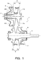
- FIG. 1 is a schematic configuration view showing a continuously variable transmission (CVT) 1 of the present disclosure.
- the continuously variable transmission 1 shown in the figure is mounted on a vehicle, and has a primary shaft (first shaft) 2 as a drive side rotation shaft and a primary pulley (first pulley) provided on the primary shaft 2. 3), a secondary shaft (second shaft) 4 as a driven side rotation shaft disposed parallel to the primary shaft 2, a secondary pulley (second pulley) 5 provided on the secondary shaft 4, and a transmission belt 10 And.
- the transmission belt 10 is wound around a pulley groove (V-shaped groove) of the primary pulley 3 and a pulley groove (V-shaped groove) of the secondary pulley 5.
- the continuously variable transmission 1 further includes a primary cylinder 6 which is a hydraulic actuator for changing the groove width of the primary pulley 3 and a secondary cylinder 7 which is a hydraulic actuator for changing the groove width of the secondary pulley 5.
- the primary cylinder 6 is formed behind the movable sheave 3 b of the primary pulley 3
- the secondary cylinder 7 is formed behind the movable sheave 5 b of the secondary pulley 5.
- Hydraulic fluid is supplied to the primary cylinder 6 and the secondary cylinder 7 from a hydraulic control device (not shown) so as to change the groove width of the primary pulley 3 and the secondary pulley 5.
- the secondary shaft 4 is connected to a drive wheel (all are not shown) of the vehicle via a gear mechanism, a differential gear and a drive shaft.
- a step is formed on the end (the end on the left side in FIG. 1) of the primary shaft 2 opposite to the engine side. And, between the step and the primary piston 60 of the primary cylinder 6, the end (the end on the left side in FIG. 1) of the movable pulley 3b of the primary pulley 3 opposite to the engine side can contact An annular end plate 65 is interposed so as to be. Further, a stopper portion 2s is formed on the primary shaft 2 so as to be able to abut on an end portion of the spline teeth 3s formed on the inner peripheral surface of the movable sheave 3b on the stationary sheave 3a side.
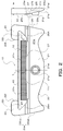
- FIG. 2 is a schematic configuration view showing the transmission belt 10.
- the transmission belt 10 is formed by laminating a plurality of elastically deformable (in this embodiment, for example, nine) ring members 11 in the thickness direction (ring radial direction). It includes a laminated ring 12, one retainer ring 15, and a plurality (for example, several hundred) of elements 20 arranged in a ring along the inner circumferential surface of the laminated ring 12.
- the element 20 includes a first element and a second element having a thickness (maximum thickness) slightly larger (for example, about 0.1 mm) than the first element, and the first element The second element and the second element are arranged adjacent to each other.
- the plurality of ring members 11 constituting the laminated ring 12 are each elastically deformable which is cut out from a drum made of a steel plate and processed so as to have substantially the same thickness and different circumferential lengths predetermined for each. It is done.
- the retainer ring 15 is elastically deformable, for example, cut out from a drum made of a steel plate, and has a thickness substantially the same as or thinner than the ring member 11. Further, the retainer ring 15 has an inner circumferential length longer than the outer circumferential length of the outermost layer ring material 11 o of the laminated ring 12.
- Each element 20 has, for example, a laterally symmetrical outer shape (planar shape) punched out of a steel plate by press processing, and as shown in FIG.
- a pair of pillars 22 extending in the same direction from both ends, and a single ring housing (a recess (concave portion) defined between the pair of pillars 22 so as to open on the free end side of each pillar 22 And 23) and a pair of side surfaces 20s formed to be separated from each other from the inner peripheral side to the outer peripheral side (the outer side in the radial direction of the laminated ring 12) of the transmission belt 10 (laminated ring 12).
- the pair of pillar portions 22 is from the both sides in the width direction of the saddle surface 23s which is the bottom surface of the ring housing portion 23 (a direction from the inner peripheral side to the outer peripheral side of the transmission belt 10 (laminated ring 12) It has been extended to Further, at the free end portion of each pillar portion 22, a hook portion 22f which protrudes in the width direction of the saddle surface 23s is formed.
- the pair of hook portions 22 f are opposed to each other at an interval slightly longer than the width of the laminated ring 12 (ring member 11) and shorter than the width of the retainer ring 15.
- each pillar portion 22 of the element 20 has a flat inner surface 22i inclined so as to be separated from the saddle surface 23s toward the outer peripheral side, and between the saddle surface 23s and the inner surface 22i of each pillar portion 22 A concave surface (for example, a concave cylindrical surface) that is smoothly continuous with both is formed.
- the laminated ring 12 is disposed in the ring accommodating portion 23, and the saddle surface 23s of the ring accommodating portion 23 contacts the laminated ring 12, that is, the inner peripheral surface of the innermost ring member 11i.
- the saddle surface 23s has a laterally symmetrical convexly curved surface shape (crowning shape) which is gently inclined downward in the figure as the central portion in the width direction goes to the outside in the width direction with the apex T.
- the saddle surface 23 s may include a plurality of convex curved surfaces that curve outward in the radial direction of the laminated ring 12.
- the elastically deformed retainer ring 15 is fitted into the ring accommodating portion 23 from between the pair of hook portions 22 f of each element 20.
- the retainer ring 15 is disposed between the outer peripheral surface of the outermost ring material 11 o of the laminated ring 12 and the hook portion 22 f of each element 20 to surround the laminated ring 12, and together with the pair of pillar portions 22, each element 20. Prevents the laminated ring 12 from falling off and the laminated ring 12 from falling off from the element 20. Thereby, the plurality of elements 20 are bound (arranged) annularly along the inner circumferential surface of the laminated ring 12.
- the retainer ring 15 is formed with a single or a plurality of openings (long holes) (not shown), whereby the retainer ring 15 is easily elastically deformed to ensure assembly with the element 20. can do.
- each side surface 20s of the element 20 is formed so as to be continuous with the first side surface 20sa and the first side surface 20sa located on the pillar portion 22 side, that is, the opposite side (outside) of the inner surface 22i of the pillar portion 22 And a second side surface 20sb positioned on the inner peripheral side (inner side in the radial direction of the laminated ring 12) than the first side surface 20sa.
- the pair of first side surfaces 20sa is formed to be separated from each other as it goes to the outer peripheral side, similarly to the second side surface 20sb. Thereby, the strength of each pillar portion 22 can be favorably secured.
- the angle formed by the pair of second side surfaces 20sb is set to be approximately equal to the opening angle of the pulley grooves of the primary pulley 3 and the secondary pulley 5 (in the present embodiment, slightly larger than the design value of the opening angle) And the angle which a pair of 1st side 20sa makes is defined smaller than the angle which a pair of 2nd side 20sb makes.
- the second side surface 20sb of the element 20 comes into frictional contact with the surface of the pulley groove of the primary pulley 3 and the surface of the pulley groove of the secondary pulley 5 and receives clamping pressure from the pulleys 3 and 5.
- the torque transmission surface (flank surface) transmits torque to the secondary pulley 5.
- the pair of first side surfaces 20sa basically do not contact the surface of the pulley groove. Further, on the surface of each second side surface 20sb, not-shown unevenness (a plurality of grooves) for holding hydraulic oil for lubricating and cooling the contact portion between the element 20 and the primary pulley 3 and the secondary pulley 5 are formed. It is done.
- the front surface (one surface) of the element 20 is a tapered surface (inclined surface) formed on the convexly curved locking edge portion (contact region) 25, the noncontact portion 27, and the trunk portion 21. Including 21s.
- the locking edge portion 25 is a convex curved surface portion formed on the front surface of the element 20 so as to straddle each pillar portion 22 and the body portion 21, and makes line contact with the back surface 20 bs of the adjacent element 20. That is, the locking edge portion 25 includes a contact line between the adjacent elements 20 which serves as a fulcrum of rotation of the elements 20.
- the non-contact portion 27 is a belt-like recess formed in the trunk portion 21 so as to open at the saddle surface 23s and extend in the width direction along the saddle surface 23s, and the locking edge portion 25 In the width direction. As shown in FIG. 3, the non-contact portion 27 is such that the depths of both ends in the width direction gradually decrease as it approaches the locking edge 25 and the portion between the both ends has a substantially constant depth d. It is formed.
- the width w of the portion having the substantially constant depth d of the non-contact portion 27 is narrower than the width of the laminated ring 12. Thereby, it is possible to suppress stress concentration in the vicinity of both end portions in the width direction of the non-contact portion 27 and to further improve the durability of the element 20.
- the tapered surface 21s is continuous with the locking edge portion 25 and approaches the back surface 20bs of the element 20 as it goes from the locking edge portion to the edge portion 21ei (lower side in the drawing) of the trunk portion 21 on the inner peripheral side of the transmission belt 10. It is a flat slope formed as. Further, one protrusion (dimple) 21p is formed on the tapered surface 21s so as to be located at the center in the width direction of the front of the body 21. The back surface 20bs of the element 20 (body 21) The recess 21 r is formed to be located on the back side of the protrusion 21 p. When the transmission belt 10 is assembled, the projections 21p of the adjacent elements 20 are loosely fitted in the depressions 21r.
- the inclination angle of the tapered surface 21s is set in consideration of the thickness te of the pillar portion 22 so that the tapered surface 21s does not contact the back surface 20bs of the adjacent element 20.
- a flat portion extending in parallel to the back surface 20bs of the element 20 may be formed around the protrusion 21p.
- the locking edge portion 25 includes a contact line serving as a fulcrum of rotation of the adjacent elements 20, but the position of the contact line corresponds to the transmission ratio ⁇ of the continuously variable transmission 1.
- An end (hereinafter referred to as an “inner peripheral end”) 25 i of an inner peripheral side of the transmission belt 10 from an end (hereinafter referred to as “an outer peripheral end”) 25 o of the locking edge 25 on the outer peripheral side of the transmission belt 10 Vary within the range of That is, when torque is transmitted from the primary pulley 3 to the secondary pulley 5 by the transmission belt 10 including the plurality of elements 20, adjacent elements in the chord portion which is a portion not wound around the pulleys 3 and 5 of the transmission belt 10
- the contact line 20 is located on the outermost side of the transmission belt 10 within the locking edge 25.
- the locking edge 25 (the radius of curvature of the cylindrical surface, etc.) is designed (theoretically) at the outer edge 25 o (the boundary between the front of the pillar 22 and the locking edge 25) at the chord It is designed to be located on the outer peripheral side than the contact line of.
- the locking edge portion 25 has an inner circumferential end 25i (a boundary line between the tapered surface 21s and the locking edge portion 25), which is the inner circumferential side of the contact line 25cmin when the winding radius of the transmission belt 10 is minimized. Designed to be located on the side. Accordingly, the locking edge portion 25 is continuous with the tapered surface 21s on the inner peripheral side of the contact line 25cmin.
- the contact line 25cmax at which the winding radius of the transmission belt 10 is maximized is included.
- the contact line 25cmin when the winding radius becomes minimum is located on the inner peripheral side with respect to the saddle surface 23s (bottom) and the winding radius becomes maximum, the locking edge portion 25 becomes maximum.
- the contact line 25cmax is designed to be located on the outer peripheral side of the saddle surface 23s (the top T).
- the winding radius of the transmission belt 10 is minimized when the gear ratio ⁇ of the continuously variable transmission 1 is minimized and is maximized when the gear ratio ⁇ is maximized, or the gear ratio ⁇ is It is minimized when maximized and maximized when gear ratio ⁇ is minimized.
- the non-contact portion 27 which is a concave portion extending along the saddle surface 23s in each element 20, in the transmission belt 10, the contact with the adjacent element 20 other than the locking edge portion 25 And the durability of each element 20 can be improved. That is, by preventing each element 20 from coming into contact with the non-contact portion 27 of the adjacent element 20, a load from the central portion in the width direction of the element 20 on which a large moment acts is applied to the adjacent element 20 It is possible to suppress deformation of the elements 20, thereby further improving the durability of each element 20.
- the elements 20 are adjacent when the winding radius of the transmission belt 10 is minimized. There is a possibility that the inner peripheral portion of the non-contact portion 27 of the element 20 may come into contact. On the other hand, when the non-contacting portion 27 is formed on the front face of the element 20 so as to reach the edge 21ei on the inner peripheral side of the trunk portion 21, the strength of the element 20 is reduced. There is a possibility that the durability of the transmission belt 10 including it may fall.
- the depth (the above-mentioned fixed depth) d of the non-contacting portion 27 of the element 20 is, as shown in FIG. , “Inside end” 27 i is positioned more inside than the contact line 25 cmin when the winding radius of the transmission belt 10 is minimized, and the inside end of the locking edge 25 It is determined to be located on the outer peripheral side than 25i (the boundary line between the tapered surface 21s and the locking edge portion 25). That is, the bottom surface 27b of the non-contact portion 27 is closer to the back surface 20bs of the element 20 than the contact line 25cmin, and is further separated from the back surface 20bs than the inner peripheral end 25i of the locking edge 25.
- the non-contact portion 27 forms a region where the locking edge portion 25 is removed from the pair of actual contact regions 25A (a portion of the locking edge portion 25 mainly located on the inner peripheral side of the contact line 25cmin, hatched portion in FIG.
- the contactless element 27 is made as shallow as possible while the element 20 is in contact with the adjacent element 20 only at the locking edge 25 located on both sides of the element 20, Thinning can be favorably suppressed.
- the strength of each element 20 can be sufficiently secured, and deformation of each element 20 during torque transmission can be suppressed, and the durability of the transmission belt 10 including the plurality of elements 20 can be further improved. it can.
- the contact line 25cmin at which the winding radius is minimized is located on the inner peripheral side relative to the saddle surface 23s, and the winding radius is maximized, as described above.
- the contact line 25cmax is designed to be located on the outer peripheral side of the saddle surface 23s.
- the winding radius becomes maximum, for example. This makes it possible to make the non-contacting portion 27 shallower than in the case where the contact line 25cmax is provided on the inner peripheral side of the saddle surface 23s in the radial direction of the transmission belt 10.
- the depth d of the non-contact portion 27 is determined depending on the specifications (thickness and the like) of the element 20 such that the inner peripheral end 27i is the inner peripheral end 25i of the locking edge 25 (a tapered surface 21s and the locking edge It may be determined to be located on the border line 25). Further, depending on the curvature of the locking edge portion 25 and the inclination angle of the tapered surface 21s, the depth d of the non-contact portion 27 is a range in which the inner peripheral end 27i does not reach the inner peripheral edge 21ei of the trunk 21. It may be determined to be located on the inner peripheral side of the inner peripheral end 25i of the locking edge portion 25.
- the inner peripheral end 25i of the locking edge 25 is located on the inner peripheral side relative to the saddle surface 23s (bottom) and the outer peripheral end 25o is located on the outer peripheral side relative to the saddle surface 23s (top T). If there is, the contact line 25cmin when the winding radius is minimum may be located on the outer peripheral side than the saddle surface 23s (bottom), and the contact line 25cmax when the winding radius is maximum is the saddle surface You may be located in the inner peripheral side rather than 23s (top part T).
- the locking edge 25 is a straight line in which the inner circumferential end 25i or the outer circumferential end 25o extends in the width direction through the locking edge 25 and the top T of the saddle surface 23s (see the dashed line in FIG. 4) And so on. Furthermore, the locking edge portion 25 and the non-contact portion 27 may be formed on the back surface 20 bs of the element 20.
- the transmission belt element of the present disclosure is in contact with the ring (12) of the transmission belt (10) wound around the primary pulley (3) and the secondary pulley (5) of the continuously variable transmission (1).
- a body (21) having a saddle surface (23s), and a pair of pillars (22) extending from the body (21) so as to be positioned on both sides in the width direction of the saddle surface (23s)
- the transmission belt element (20) including at least a part of the front surface and the rear surface so as to straddle the pillar portion (22), and rotation between the adjacent transmission belt elements (20)
- the saddle surface (2) so as not to come into contact with the convexly curved locking edge (25) including the contact line between the two acting as the fulcrum of the shaft and the adjacent transmission belt element (20) a non-contacting portion (27) extending in the width direction along s), the non-contacting portion (27) dividing the locking edge portion (25) at least partially in the width direction; 27) depth (d), when the end (27i) on the inner peripheral side of
- the locking edge portion is at least partially separated in the width direction by the non-contact portion. Furthermore, the depth of the noncontacting portion is such that the end on the inner circumferential side of the transmission belt of the noncontacting portion is positioned on the inner circumferential side relative to the contact line when the winding radius of the transmission belt is minimized. , And is determined not to reach the inner peripheral edge of the body.
- the transmission belt It is possible to secure sufficient strength of the element and to suppress deformation of the transmission belt element during torque transmission. As a result, the durability of the transmission belt including the transmission belt element of the present disclosure can be further improved.
- the one of the front surface and the back surface is continuous with the locking edge portion (25) on the inner peripheral side with respect to the contact line (25cmin) when the winding radius is minimized
- the locking edge portion (25s) may include a slope (21s) closer to the other (20bs) of the front and back as going from the (25) to the inner circumferential side, and the depth (d) of the noncontact portion (27)
- the end (27i) on the inner peripheral side of the contact portion (27) is an outer peripheral side of the transmission belt (10) or a boundary line (25i) between the locking edge (25) and the slope (21s) It may be defined to be located on the boundary line (25i).
- the noncontact parts are made shallower and the thinning of the transmission belt element is favorably suppressed. It is possible to
- the contact line (25cmin) when the winding radius is minimum may be positioned on the inner peripheral side with respect to the saddle surface (23s), and the contact radius (25cmin) when the winding radius becomes maximum
- the contact line (25cmax) may be located on the outer peripheral side of the transmission belt (10) than the saddle surface (23s).
- the non-contact portion (27) gradually decreases as the depths of both ends in the width direction approach the locking edge (25), and the portion between the both ends has a constant depth (d) It may be formed to have, and the depth of the non-contact portion (27) may be the constant depth (d). As a result, it is possible to suppress the stress concentration in the vicinity of both end portions in the width direction of the non-contact portion and to further improve the durability of the transmission belt element.
- width (w) of the portion having the constant depth (d) of the non-contacting portion (27) may be narrower than the width of the ring (12).
- the transmission belt element (20) may further include a pair of hook portions (22f) projecting in the width direction so as to face each other from the free end portion of the pillar portion (22), and the ring ( A retainer ring (15) may be disposed between 12) and the hook portion (22f).
- the retainer ring can limit the transmission belt element from dropping off from the ring and the plurality of transmission belt elements from dropping off from the ring.
- the transmission belt of the present disclosure includes a body (21) having a saddle surface (23s) and a pair of pillars extended from the body (21) so as to be located on both sides in the width direction of the saddle surface (23s).
- a plurality of elements (20) having a portion (22), and a ring (12) disposed between the pair of pillar portions (22) of the plurality of elements (20) so as to contact the saddle surface (23s)
- each of the elements (20) has at least one of a front surface and a rear surface
- a convexly curved lock having a contact line between the adjacent elements (20) which is partially formed to straddle the pillar portion (22) and serves as a fulcrum of rotation of the adjacent elements (20).
- a recess extending in the width direction along the saddle surface (23s) so as not to contact the gedge portion (25) and the adjacent element (20), at least a portion of the locking edge portion (25) And the non-contact portion (27) divided in the width direction, and the depth (d) of the non-contact portion (27) is the inner circumference of the transmission belt (10) of the non-contact portion (27)
- the end (27i) on the side is positioned on the inner peripheral side with respect to the contact line (25cmin) when the winding radius of the transmission belt (10) is minimized, and the end of the body (21) It is determined so as not to reach the inner peripheral edge (21 ei).
- the transmission belt of the present disclosure since the thinning of each element can be suppressed, the strength of the element is ensured while the adjacent elements are in contact with the adjacent elements only at the locking edge portions located on both sides of the noncontact portion. While ensuring sufficient deformation of the element during torque transmission. As a result, in the transmission belt of the present disclosure, the durability can be further improved.
- the invention of the present disclosure can be used in the manufacturing industry of continuously variable transmissions and transmission belts.
Landscapes
- Engineering & Computer Science (AREA)
- General Engineering & Computer Science (AREA)
- Mechanical Engineering (AREA)
- Transmissions By Endless Flexible Members (AREA)
Abstract
無段変速機のプーリに巻き掛けられる伝動ベルトのエレメントは、正面および背面の一方に少なくとも部分的にピラー部に跨がるように形成され、隣り合うエレメント同士の回動の支点となる両者の接触線を含む凸曲面状のロッキングエッジ部と、隣り合うエレメントと接触しないようにサドル面に沿って幅方向に延在する凹部であって、ロッキングエッジ部を少なくとも部分的に幅方向に分断する非接触部とを含み、非接触部の深さは、当該非接触部の伝動ベルトの内周側における端部が、当該伝動ベルトの巻き掛け半径が最小になるときの接触線よりも内周側に位置すると共に胴部の内周側の縁部に達しないように定められる。
Description
本開示は、無段変速機のプーリに巻き掛けられる伝動ベルトのリングと接触するサドル面を有する胴部と、サドル面の幅方向における両側に位置するように当該胴部から延出された一対のピラー部とを含む伝動ベルト用エレメントおよびそれを備えた伝動ベルトに関する。
従来、伝動ベルト用エレメントとして、左右に延びるボディ部と、当該ボディ部の上部の左右端からそれぞれ上方に延びる一対のピラー部と、前側主面に形成されて左右に延びるロッキングエッジ部とを有するものが知られている(例えば、特許文献1参照)。このエレメントの前側主面には、左右に延びるロッキングエッジ部の下部に位置するように傾斜面が形成されており、当該エレメントの板厚は、下端に向かうにつれて薄くなっている。更に、エレメントの前側主面または後側主面の左右方向略中央部には、上下に延びる凹部(非接触部)が形成されている。これにより、このエレメントを含む伝動ベルトでは、隣り合うエレメント同士を凹部の両側で接触させてミスアライメントを吸収すると共にヨーイングを抑制している。
しかしながら、上記特許文献1に記載されたエレメントでは、前側主面または後側主面に当該エレメントの下端(下縁部)に達する凹部が形成されることで強度が低下してしまう。このため、エレメント自体の強度低下やトルク伝達中のエレメントの変形に起因して、当該エレメントを複数含む伝動ベルトの耐久性が低下するおそれがある。
そこで、本開示は、伝動ベルト用エレメントが隣り合うエレメントに非接触部の両側に位置するロッキングエッジ部のみで接触するようにしつつ、当該伝動ベルト用エレメントの強度を充分に確保して伝動ベルトの耐久性をより向上させることを主目的とする。
本開示の伝動ベルト用エレメントは、無段変速機のプライマリプーリおよびセカンダリプーリに巻き掛けられる伝動ベルトのリングと接触するサドル面を有する胴部と、前記サドル面の幅方向における両側に位置するように前記胴部から延出された一対のピラー部とを含む伝動ベルト用エレメントにおいて、正面および背面の一方に少なくとも部分的に前記ピラー部に跨がるように形成され、隣り合う前記伝動ベルト用エレメント同士の回動の支点となる両者の接触線を含む凸曲面状のロッキングエッジ部と、隣り合う前記伝動ベルト用エレメントと接触しないように前記サドル面に沿って前記幅方向に延在する凹部であって、前記ロッキングエッジ部を少なくとも部分的に該幅方向に分断する非接触部とを備え、前記非接触部の深さは、該非接触部の前記伝動ベルトの内周側における端部が、該伝動ベルトの巻き掛け半径が最小になるときの前記接触線よりも前記内周側に位置すると共に、前記胴部の前記内周側の縁部に達しないように定められるものである。
本開示の伝動ベルト用エレメントにおいて、ロッキングエッジ部は、非接触部によって少なくとも部分的に幅方向に分断される。更に、非接触部の深さは、当該非接触部の伝動ベルトの内周側における端部が、当該伝動ベルトの巻き掛け半径が最小になるときの接触線よりも内周側に位置すると共に、胴部の内周側の縁部に達しないように定められる。これにより、伝動ベルト用エレメントが隣り合うエレメントに非接触部の両側に位置するロッキングエッジ部のみで接触するようにしつつ、伝動ベルト用エレメントの薄肉化を抑制することができるので、当該伝動ベルト用エレメントの強度を充分に確保すると共にトルク伝達中の伝動ベルト用エレメントの変形を抑制することが可能となる。この結果、本開示の伝動ベルト用エレメントを含む伝動ベルトの耐久性をより向上させることができる。
次に、図面を参照しながら、本開示の発明を実施するための形態について説明する。
図1は、本開示の無段変速機(CVT)1を示す概略構成図である。同図に示す無段変速機1は、車両に搭載されるものであり、駆動側回転軸としてのプライマリシャフト(第1シャフト)2と、当該プライマリシャフト2に設けられたプライマリプーリ(第1プーリ)3と、プライマリシャフト2と平行に配置される従動側回転軸としてのセカンダリシャフト(第2シャフト)4と、当該セカンダリシャフト4に設けられたセカンダリプーリ(第2プーリ)5と、伝動ベルト10とを含む。図示するように、伝動ベルト10は、プライマリプーリ3のプーリ溝(V字状溝)とセカンダリプーリ5のプーリ溝(V字状溝)とに巻き掛けられる。
プライマリシャフト2は、車両のエンジン(内燃機関)といった動力発生源に連結されたインプットシャフト(図示省略)に図示しない前後進切換機構を介して連結される。プライマリプーリ3は、プライマリシャフト2と一体に形成された固定シーブ3aと、ボールスプライン等を介してプライマリシャフト2により軸方向に摺動自在に支持される可動シーブ3bとを含む。また、セカンダリプーリ5は、セカンダリシャフト4と一体に形成された固定シーブ5aと、ボールスプライン等を介してセカンダリシャフト4により軸方向に摺動自在に支持されると共にリターンスプリング8により軸方向に付勢される可動シーブ5bとを含む。
更に、無段変速機1は、プライマリプーリ3の溝幅を変更するための油圧式アクチュエータであるプライマリシリンダ6と、セカンダリプーリ5の溝幅を変更するための油圧式アクチュエータであるセカンダリシリンダ7とを含む。プライマリシリンダ6は、プライマリプーリ3の可動シーブ3bの背後に形成され、セカンダリシリンダ7は、セカンダリプーリ5の可動シーブ5bの背後に形成される。プライマリシリンダ6とセカンダリシリンダ7とには、プライマリプーリ3とセカンダリプーリ5との溝幅を変化させるべく図示しない油圧制御装置から作動油が供給される。また、セカンダリシャフト4は、ギヤ機構、デファレンシャルギヤおよびドライブシャフトを介して車両の駆動輪(何れも図示省略)に連結される。
本実施形態において、プライマリシャフト2のエンジン側とは反対側の端部(図1における左側の端部)には、段部が形成されている。そして、当該段部とプライマリシリンダ6のプライマリピストン60との間には、プライマリプーリ3の可動シーブ3bのエンジン側とは反対側の端部(図1における左側の端部)と当接可能となるように、環状のエンドプレート65が介設されている。更に、プライマリシャフト2には、可動シーブ3bの内周面に形成されたスプライン歯3sの固定シーブ3a側の端部と当接可能となるようにストッパ部2sが形成されている。
プライマリプーリ3の可動シーブ3bが固定シーブ3aから離間してエンドプレート65に当接すると、プライマリシャフト2に対する可動シーブ3bの固定シーブ3aから離間する方向への移動が規制される。これにより、プライマリプーリ3のプーリ溝の幅が最大になり、それに伴ってセカンダリプーリ5のプーリ溝の幅が最小に設定されることで、無段変速機1の変速比γが最大になる。また、可動シーブ3bの内周面に形成されたスプライン歯3sがプライマリシャフト2に形成されたストッパ部2sに当接すると、プライマリシャフト2に対する可動シーブ3bの固定シーブ3aに接近する方向への移動が規制される。これにより、プライマリプーリ3のプーリ溝の幅が最小になり、それに伴って伝動ベルト10によりセカンダリプーリ5のプーリ溝の幅が最大に設定されることで、無段変速機1の変速比γが最小になる。なお、無段変速機1は、プライマリシャフト2およびセカンダリシャフト4が選択的にインプットシャフトに連結されると共に、プライマリシャフト2およびセカンダリシャフト4が選択的に車両のドライブシャフトに連結されるように構成されてもよい。
図2は、伝動ベルト10を示す概略構成図である。同図に示すように、伝動ベルト10は、弾性変形可能な複数(本実施形態では、例えば9個)のリング材11を厚み方向(リング径方向)に積層することにより構成された1個の積層リング12と、1個のリテーナリング15と、積層リング12の内周面に沿って環状に配列(結束)される複数(例えば、数百個)のエレメント20とを含む。本実施形態において、エレメント20は、第1のエレメントと、当該第1のエレメントよりも若干(例えば、0.1mm程度)大きい厚み(最大厚み)を有する第2のエレメントとを含み、当該第1および第2エレメントは、それぞれ複数個隣り合わせにして配列される。これにより、伝動ベルト10によってプライマリプーリ3およびセカンダリプーリ5との間でトルク伝達される際に、振動やノイズが発生するのを抑制することが可能となる。第1および第2エレメントの厚み以外の構造は共通であることから、以下、両者を「エレメント20」と総称して説明する。
積層リング12を構成する複数のリング材11は、それぞれ鋼板製のドラムから切り出された弾性変形可能なものであって、概ね同一の厚みおよびそれぞれについて予め定められた異なる周長を有するように加工されている。リテーナリング15は、例えば鋼板製のドラムから切り出された弾性変形可能なものであり、リング材11と概ね同一若しくはそれよりも薄い厚みを有する。また、リテーナリング15は、積層リング12の最外層リング材11oの外周長よりも長い内周長を有する。これにより、積層リング12とリテーナリング15とが同心円状に配置された状態(張力が作用しない無負荷状態)では、図2に示すように、最外層リング材11oの外周面とリテーナリング15の内周面との間に、環状のクリアランスが形成される。
各エレメント20は、例えばプレス加工により鋼板から打ち抜かれた左右対称の外形(平面形状)を有するものであり、図2に示すように、図中水平に延びる胴部21と、当該胴部21の両端部から同方向に延出された一対のピラー部22と、各ピラー部22の遊端側に開口するように一対のピラー部22の間に画成された単一のリング収容部(凹部)23と、伝動ベルト10(積層リング12)の内周側から外周側(積層リング12の径方向における外側)に向かうにつれて互いに離間するように形成された一対の側面20sとを有する。
一対のピラー部22は、リング収容部23の底面であるサドル面23sの幅方向における両側から外周側(伝動ベルト10(積層リング12)の内周側から外周側に向かう方向、すなわち図中上方)に延出されている。また、各ピラー部22の遊端部には、サドル面23sの幅方向に突出するフック部22fが形成されている。一対のフック部22fは、積層リング12(リング材11)の幅よりも若干長く、かつリテーナリング15の幅よりも短い間隔をおいて互いに対向する。また、エレメント20の各ピラー部22は、外周側に向かうにつれてサドル面23sから離間するように傾斜した平坦な内面22iを有し、サドル面23sと各ピラー部22の内面22iとの間には、両者に滑らかに連続する凹曲面(例えば、凹円柱面)が形成されている。
リング収容部23内には、図2に示すように、積層リング12が配置され、当該リング収容部23のサドル面23sは、積層リング12すなわち最内層リング材11iの内周面に接触する。サドル面23sは、幅方向における中央部を頂部Tとして幅方向外側に向かうにつれて図中下方に緩やかに傾斜した左右対称の凸曲面形状(クラウニング形状)を有する。これにより、サドル面23sとの摩擦により積層リング12に頂部Tに向かう求心力を付与して、当該積層リング12をセンタリングすることが可能となる。ただし、サドル面23sは、積層リング12の径方向における外側に湾曲する凸曲面を複数含むものであってもよい。
更に、リング収容部23内には、弾性変形させられたリテーナリング15が各エレメント20の一対のフック部22fの間から嵌め込まれる。リテーナリング15は、積層リング12の最外層リング材11oの外周面と各エレメント20のフック部22fとの間に配置されて当該積層リング12を包囲し、一対のピラー部22と共に、各エレメント20が積層リング12から脱落したり、エレメント20から積層リング12が脱落したりするのを規制する。これにより、複数のエレメント20は、積層リング12の内周面に沿って環状に結束(配列)される。本実施形態において、リテーナリング15には、図示しない単一または複数の開口(長穴)が形成されており、これにより、リテーナリング15を弾性変形し易くしてエレメント20に対する組付性を確保することができる。
積層リング12の最外層リング材11oの外周面とリテーナリング15の内周面との間には、上述のようにクリアランスが形成され、無段変速機1の作動中、基本的にリテーナリング15に張力等が作用することがない。従って、エレメント20では、剛性等の確保のためにピラー部22やフック部22fを大きくする必要がなくなり、胴部の幅方向における中央部から外周側に延出された頭部の両側に積層リングが配置される一般的なエレメントに比べて、ピラー部22の積層リング12よりも外周側に突出する部分の面積を減らすことができる。従って、エレメント20の材料費の低減化により、伝動ベルト10ひいては無段変速機1の低コスト化を図ることが可能となる。
また、エレメント20の各側面20sは、ピラー部22側すなわち当該ピラー部22の内面22iの反対側(外側)に位置する第1側面20saと、第1側面20saに連続するように形成されて当該第1側面20saよりも内周側(積層リング12の径方向における内側)に位置する第2側面20sbとを含む。本実施形態において、一対の第1側面20saは、第2側面20sbと同様に、外周側に向かうにつれて互いに離間するように形成される。これにより、各ピラー部22の強度を良好に確保することができる。
一対の第2側面20sbがなす角度は、プライマリプーリ3やセカンダリプーリ5のプーリ溝の開き角度と概ね等しく(本実施形態では、開き角度の設計値よりも僅かに大きく)なるように定められ、かつ一対の第1側面20saがなす角度は、一対の第2側面20sbがなす角度よりも小さく定められている。これにより、エレメント20の第2側面20sbは、プライマリプーリ3のプーリ溝やセカンダリプーリ5のプーリ溝の表面に摩擦接触してプーリ3,5からの挟圧力を受け、摩擦力によりプライマリプーリ3からセカンダリプーリ5へとトルクを伝達するトルク伝達面(フランク面)となる。これに対して、一対の第1側面20saは、伝動ベルト10によってプライマリプーリ3からセカンダリプーリ5へとトルクが伝達される際、基本的に、プーリ溝の表面に接触しないことになる。また、各第2側面20sbの表面には、エレメント20とプライマリプーリ3やセカンダリプーリ5との接触部を潤滑・冷却するための作動油を保持するための図示しない凹凸(複数の溝)が形成されている。
図2に示すように、エレメント20の正面(一方の表面)は、凸曲面状のロッキングエッジ部(接触領域)25と、非接触部27と、胴部21に形成されたテーパ面(斜面)21sと含む。ロッキングエッジ部25は、各ピラー部22と胴部21とに跨がるようにエレメント20の正面に形成された凸曲面部であって、隣り合うエレメント20の背面20bsに線接触する。すなわち、ロッキングエッジ部25は、隣り合うエレメント20同士の回動の支点となる両者の接触線を含むものである。
また、非接触部27は、サドル面23sで開口すると共に当該サドル面23sに沿って幅方向に延在するように胴部21に形成された帯状の凹部であって、ロッキングエッジ部25を部分的に当該幅方向に分断するものである。図3に示すように、非接触部27は、幅方向における両端部の深さがロッキングエッジ部25に近接するにつれて漸減すると共に両端部の間の部分が略一定の深さdを有するように形成されている。そして、非接触部27の略一定の深さdを有する部分の幅wは、積層リング12の幅よりも狭くなっている。これにより、非接触部27の幅方向における両端部付近での応力集中を抑制してエレメント20の耐久性をより向上させることが可能となる。
テーパ面21sは、ロッキングエッジ部25に連続すると共に当該ロッキングエッジ部から伝動ベルト10の内周側における胴部21の縁部21ei(図中下側)に向かうにつれてエレメント20の背面20bsに近接するように形成された平坦な斜面である。また、テーパ面21sには、胴部21の正面の幅方向における中央部に位置するように1個の突起(ディンプル)21pが形成されており、エレメント20(胴部21)の背面20bsには、突起21pの裏側に位置するように窪み部21rが形成されている。伝動ベルト10が組み立てられた際、当該窪み部21rには、隣り合うエレメント20の突起21pが遊嵌される。
本実施形態において、ロッキングエッジ部25の外周側(図2における上側)におけるエレメント20の正面(主にピラー部22の正面)と、エレメント20の背面20bs(他方の表面)とは、図2に示すように、それぞれ平坦かつ互いに平行に形成されている。これにより、エレメント20のピラー部22は、略一定の厚みteを有する。また、非接触部27は、ロッキングエッジ部25の表面よりも背面20bs側に窪んでいることから、サドル面23sの厚みは、ピラー部22の厚みteよりも小さくなる。そして、テーパ面21sの傾斜角度は、当該テーパ面21sが隣り合うエレメント20の背面20bsに接触しないようにピラー部22の厚みteを考慮して設定される。なお、突起21pの周囲には、エレメント20の背面20bsと平行に延在する平坦部が形成されてもよい。
図4は、エレメント20を示す要部拡大部分断面図である。同図に示すように、ロッキングエッジ部25は、ピラー部22の正面とテーパ面21sとに滑らかに連続すると共に伝動ベルト10の径方向に幅をもつように形成されている。本実施形態において、ロッキングエッジ部25は、予め定められた曲率半径を有すると共にピラー部22の正面およびテーパ面21sの双方に接する円柱面により形成されている。ただし、ロッキングエッジ部25は、円柱面以外の楕円柱面といった凸曲面により形成されてもよい。
また、ロッキングエッジ部25は、上述のように、隣り合うエレメント20同士の回動の支点となる接触線を含むが、当該接触線の位置は、無段変速機1の変速比γに応じてロッキングエッジ部25の伝動ベルト10の外周側における端部(以下、「外周側端部」という)25oから伝動ベルト10の内周側における端部(以下、「内周側端部」という)25iまでの範囲内で変動する。すなわち、複数のエレメント20を含む伝動ベルト10によりプライマリプーリ3からセカンダリプーリ5にトルクが伝達される際、伝動ベルト10のプーリ3,5に巻き掛かっていない部分である弦部において、隣り合うエレメント20同士の接触線がロッキングエッジ部25内で最も伝動ベルト10の外周側に位置する。また、隣り合うエレメント20同士の接触線は、理論上、伝動ベルト10の巻き掛け半径が最小になるときに、エレメント20の傾きが最大になることでロッキングエッジ部25内で最も伝動ベルト10の内周側に位置する。
このため、ロッキングエッジ部25(上記円柱面の曲率半径等)は、外周側端部25o(ピラー部22の正面とロッキングエッジ部25との境界線)が上記弦部における設計上(理論上)の接触線よりも外周側に位置するように設計される。また、ロッキングエッジ部25は、内周側端部25i(テーパ面21sとロッキングエッジ部25との境界線)が、伝動ベルト10の巻き掛け半径が最小になるときの接触線25cminよりも内周側に位置するように設計される。これにより、ロッキングエッジ部25は、当該接触線25cminよりも内周側でテーパ面21sに連続することになる。本実施形態において、ロッキングエッジ部25は、図示するように、エレメント20等の製造公差や運転中の変形量等を考慮して内周側端部25iが接触線25cminから内周側に充分に(ある程度)離間するように設計されている。
更に、ロッキングエッジ部25の外周側端部25oから接触線25cminまでの範囲内には、伝動ベルト10の巻き掛け半径が最大になるときの接触線25cmaxが含まれる。そして、本実施形態において、ロッキングエッジ部25は、巻き掛け半径が最小になるときの接触線25cminがサドル面23s(底部)よりも内周側に位置し、かつ巻き掛け半径が最大になるときの接触線25cmaxがサドル面23s(頂部T)よりも外周側に位置するように設計される。これにより、トルク伝達中のプーリ3,5に巻き掛かっている伝動ベルト10の径方向におけるサドル面23sとエレメント20同士の接触線との距離をより短くすることができるので、積層リング12とエレメント20との角速度差をより一層小さくし、積層リング12とエレメント20との相対すべりによる摩擦損失を良好に低減化することが可能となる。なお、伝動ベルト10の巻き掛け半径は、無段変速機1の変速比γが最小になるときに最小になり、かつ変速比γが最大になるときに最大になるか、あるいは変速比γが最大になるときに最小になり、かつ変速比γが最小になるときに最大になる。
ここで、上述のようにサドル面23sに沿って延びる凹部である非接触部27を各エレメント20に形成することで、伝動ベルト10では、隣り合うエレメント20とのロッキングエッジ部25以外での接触を抑制して各エレメント20の耐久性を向上させることができる。すなわち、各エレメント20が隣り合うエレメント20の非接触部27と接触しないようにすることで、大きなモーメントが作用するエレメント20の幅方向における中央部からの荷重が隣り合うエレメント20に加えられて当該エレメント20が変形するのを抑制し、それにより各エレメント20の耐久性をより向上させることが可能となる。
ただし、非接触部27の伝動ベルト10の内周側における端部が上記接触線25cminよりも外周側に位置すると、当該伝動ベルト10の巻き掛け半径が最小になるときに各エレメント20が隣り合うエレメント20の非接触部27よりも内周側の部分に接触してしまうおそれがある。その一方で、エレメント20の正面に胴部21の内周側の縁部21eiまで達するように非接触部27が形成された場合、当該エレメント20の強度が低下してしまい、複数のエレメント20を含む伝動ベルト10の耐久性が低下するおそれがある。
これを踏まえて、エレメント20の非接触部27の深さ(上記一定の深さ)dは、図4に示すように、当該非接触部27の伝動ベルト10の内周側における端部(以下、「内周側端部」という)27iが、当該伝動ベルト10の巻き掛け半径が最小になるときの接触線25cminよりも内周側に位置すると共に、ロッキングエッジ部25の内周側端部25i(テーパ面21sとロッキングエッジ部25との境界線)よりも外周側に位置するように定められる。すなわち、非接触部27の底面27bは、接触線25cminよりもエレメント20の背面20bsに近接すると共に、ロッキングエッジ部25の内周側端部25iよりも背面20bsから離間する。
これにより、非接触部27によってロッキングエッジ部25を一対の実接触領域25A(ロッキングエッジ部25から主に上記接触線25cminの内周側に位置する部分を除いた領域、図2における網掛け部参照)に分断して各エレメント20が隣り合うエレメント20に当該非接触部27の両側に位置するロッキングエッジ部25のみで接触するようにしつつ、非接触部27をできるだけ浅くして当該エレメント20の薄肉化を良好に抑制することができる。この結果、各エレメント20の強度を充分に確保すると共に、トルク伝達中の各エレメント20の変形を抑制することが可能となり、複数のエレメント20を含む伝動ベルト10の耐久性をより向上させることができる。
また、エレメント20のロッキングエッジ部25は、上述のように、巻き掛け半径が最小になるときの接触線25cminがサドル面23sよりも内周側に位置し、かつ巻き掛け半径が最大になるときの接触線25cmaxがサドル面23sよりも外周側に位置するように設計される。かかるエレメント20において、非接触部27の内周側端部27iをロッキングエッジ部25の内周側端部25iよりも外周側に位置するようにすることで、例えば巻き掛け半径が最大になるときの接触線25cmaxが伝動ベルト10の径方向においてサドル面23sよりも内周側に設けられた場合に比べて非接触部27をより浅くすることが可能となる。
なお、エレメント20の諸元(厚み等)によっては、非接触部27の深さdは、内周側端部27iがロッキングエッジ部25の内周側端部25i(テーパ面21sとロッキングエッジ部25との境界線)上に位置するように定められてもよい。また、ロッキングエッジ部25の曲率やテーパ面21sの傾斜角度によっては、非接触部27の深さdは、内周側端部27iが胴部21の内周側の縁部21eiに達しない範囲でロッキングエッジ部25の内周側端部25iよりも内周側に位置するように定められてもよい。
更に、ロッキングエッジ部25の内周側端部25iがサドル面23s(底部)よりも内周側に位置すると共に外周側端部25oがサドル面23s(頂部T)よりも外周側に位置するのであれば、巻き掛け半径が最小になるときの接触線25cminは、サドル面23s(底部)よりも外周側に位置してもよく、巻き掛け半径が最大になるときの接触線25cmaxは、サドル面23s(頂部T)よりも内周側に位置してもよい。また、ロッキングエッジ部25は、内周側端部25iまたは外周側端部25oがロッキングエッジ部25とサドル面23sの頂部Tを通って幅方向に延在する直線(図4における一点鎖線参照)と重なり合うように形成されてもよい。更に、ロッキングエッジ部25や非接触部27は、エレメント20の背面20bsに形成されてもよい。
以上説明したように、本開示の伝動ベルト用エレメントは、無段変速機(1)のプライマリプーリ(3)およびセカンダリプーリ(5)に巻き掛けられる伝動ベルト(10)のリング(12)と接触するサドル面(23s)を有する胴部(21)と、前記サドル面(23s)の幅方向における両側に位置するように前記胴部(21)から延出された一対のピラー部(22)とを含む伝動ベルト用エレメント(20)において、正面および背面の一方に少なくとも部分的に前記ピラー部(22)に跨がるように形成され、隣り合う前記伝動ベルト用エレメント(20)同士の回動の支点となる両者の接触線を含む凸曲面状のロッキングエッジ部(25)と、隣り合う前記伝動ベルト用エレメント(20)と接触しないように前記サドル面(23s)に沿って前記幅方向に延在する凹部であって、前記ロッキングエッジ部(25)を少なくとも部分的に該幅方向に分断する非接触部(27)とを備え、前記非接触部(27)の深さ(d)は、該非接触部(27)の前記伝動ベルト(10)の内周側における端部(27i)が、該伝動ベルト(10)の巻き掛け半径が最小になるときの前記接触線(25cmin)よりも前記内周側に位置すると共に、前記胴部(21)の前記内周側の縁部(21ei)に達しないように定められるものである。
本開示の伝動ベルト用エレメントにおいて、ロッキングエッジ部は、非接触部によって少なくとも部分的に幅方向に分断される。更に、非接触部の深さは、当該非接触部の伝動ベルトの内周側における端部が、当該伝動ベルトの巻き掛け半径が最小になるときの接触線よりも内周側に位置すると共に、胴部の内周側の縁部に達しないように定められる。これにより、伝動ベルト用エレメントが隣り合うエレメントに非接触部の両側に位置するロッキングエッジ部のみで接触するようにしつつ、伝動ベルト用エレメントの薄肉化を抑制することができるので、当該伝動ベルト用エレメントの強度を充分に確保すると共にトルク伝達中の伝動ベルト用エレメントの変形を抑制することが可能となる。この結果、本開示の伝動ベルト用エレメントを含む伝動ベルトの耐久性をより向上させることができる。
また、前記正面および前記背面の前記一方は、前記巻き掛け半径が最小になるときの前記接触線(25cmin)よりも前記内周側で前記ロッキングエッジ部(25)に連続すると共に該ロッキングエッジ部(25)から前記内周側に向かうにつれて前記正面および前記背面の他方(20bs)に近接する斜面(21s)を含んでもよく、前記非接触部(27)の前記深さ(d)は、該非接触部(27)の前記内周側の端部(27i)が、前記ロッキングエッジ部(25)と前記斜面(21s)との境界線(25i)よりも前記伝動ベルト(10)の外周側若しくは該境界線(25i)上に位置するように定められてもよい。これにより、伝動ベルト用エレメントが隣り合うエレメントに非接触部の両側に位置するロッキングエッジ部のみで接触するようにしつつ、非接触部をより浅くして伝動ベルト用エレメントの薄肉化を良好に抑制することが可能となる。
更に、前記ロッキングエッジ部(25)の前記内周側の端部(25i)は、前記サドル面(23s)よりも前記内周側に位置してもよく、前記ロッキングエッジ部(25)の前記外周側の端部(25o)は、前記サドル面(23s)よりも前記伝動ベルト(10)の外周側に位置してもよい。
また、前記巻き掛け半径が最小になるときの前記接触線(25cmin)は、前記サドル面(23s)よりも前記内周側に位置してもよく、前記巻き掛け半径が最大になるときの前記接触線(25cmax)は、前記サドル面(23s)よりも前記伝動ベルト(10)の外周側に位置してもよい。これにより、非接触部をより浅くしつつ、トルク伝達中の伝動ベルトの径方向におけるサドル面とエレメント同士の接触線との距離をより短くすることができるので、リングと伝動ベルト用エレメントとの角速度差をより一層小さくし、リングと伝動ベルト用エレメントとの相対すべりによる摩擦損失を良好に低減化することが可能となる。
更に、非接触部(27)は、前記幅方向における両端部の深さが前記ロッキングエッジ部(25)に近接するにつれて漸減すると共に前記両端部の間の部分が一定の深さ(d)を有するように形成されてもよく、前記非接触部(27)の前記深さは、前記一定の深さ(d)であってもよい。これにより、非接触部の幅方向における両端部付近での応力集中を抑制して伝動ベルト用エレメントの耐久性をより向上させることが可能となる。
また、前記非接触部(27)の前記一定の深さ(d)を有する部分の幅(w)は、前記リング(12)の幅よりも狭くてもよい。
更に、前記伝動ベルト用エレメント(20)は、前記ピラー部(22)の遊端部から互いに対向するように前記幅方向に突出する一対のフック部(22f)を更に含んでもよく、前記リング(12)と前記フック部(22f)との間には、リテーナリング(15)が配置されてもよい。これにより、リテーナリングによって、伝動ベルト用エレメントがリングから脱落したり、複数の伝動ベルト用エレメントからリングが脱落したりするのを規制することが可能となる。
本開示の伝動ベルトは、サドル面(23s)を有する胴部(21)および前記サドル面(23s)の幅方向における両側に位置するように前記胴部(21)から延出された一対のピラー部(22)を有する複数のエレメント(20)と、前記サドル面(23s)に接触するように前記複数のエレメント(20)の前記一対のピラー部(22)間に配置されるリング(12)とを含み、無段変速機(1)のプライマリプーリ(3)およびセカンダリプーリ(5)に巻き掛けられる伝動ベルト(10)において、前記エレメント(20)の各々は、正面および背面の一方に少なくとも部分的に前記ピラー部(22)に跨がるように形成されると共に隣り合う前記エレメント(20)同士の回動の支点となる両者の接触線を含む凸曲面状のロッキングエッジ部(25)と、隣り合う前記エレメント(20)と接触しないように前記サドル面(23s)に沿って前記幅方向に延在する凹部であって、前記ロッキングエッジ部(25)を少なくとも部分的に該幅方向に分断する非接触部(27)とを有し、前記非接触部(27)の深さ(d)は、該非接触部(27)の前記伝動ベルト(10)の内周側における端部(27i)が、該伝動ベルト(10)の巻き掛け半径が最小になるときの前記接触線(25cmin)よりも前記内周側に位置すると共に、前記胴部(21)の前記内周側の縁部(21ei)に達しないように定められるものである。
本開示の伝動ベルトでは、各エレメントの薄肉化を抑制することができるので、各エレメントが隣り合うエレメントに非接触部の両側に位置するロッキングエッジ部のみで接触するようにしつつ、当該エレメントの強度を充分に確保すると共にトルク伝達中のエレメントの変形を抑制することが可能となる。この結果、本開示の伝動ベルトでは、耐久性をより向上させることができる。
そして、本開示の発明は上記実施形態に何ら限定されるものではなく、本開示の外延の範囲内において様々な変更をなし得ることはいうまでもない。更に、上記実施形態は、あくまで発明の概要の欄に記載された発明の具体的な一形態に過ぎず、発明の概要の欄に記載された発明の要素を限定するものではない。
本開示の発明は、無段変速機や伝動ベルトの製造産業等において利用可能である。
Claims (8)
- 無段変速機のプライマリプーリおよびセカンダリプーリに巻き掛けられる伝動ベルトのリングと接触するサドル面を有する胴部と、前記サドル面の幅方向における両側に位置するように前記胴部から延出された一対のピラー部とを含む伝動ベルト用エレメントにおいて、
正面および背面の一方に少なくとも部分的に前記ピラー部に跨がるように形成され、隣り合う前記伝動ベルト用エレメント同士の回動の支点となる両者の接触線を含む凸曲面状のロッキングエッジ部と、
隣り合う前記伝動ベルト用エレメントと接触しないように前記サドル面に沿って前記幅方向に延在する凹部であって、前記ロッキングエッジ部を少なくとも部分的に該幅方向に分断する非接触部とを備え、
前記非接触部の深さは、該非接触部の前記伝動ベルトの内周側における端部が、該伝動ベルトの巻き掛け半径が最小になるときの前記接触線よりも前記内周側に位置すると共に、前記胴部の前記内周側の縁部に達しないように定められる伝動ベルト用エレメント。 - 請求項1に記載の伝動ベルト用エレメントにおいて、
前記正面および前記背面の前記一方は、前記巻き掛け半径が最小になるときの前記接触線よりも前記内周側で前記ロッキングエッジ部に連続すると共に該ロッキングエッジ部から前記内周側に向かうにつれて前記正面および前記背面の他方に近接する斜面を含み、
前記非接触部の前記深さは、該非接触部の前記内周側の端部が、前記ロッキングエッジ部と前記斜面との境界線よりも前記伝動ベルトの外周側若しくは該境界線上に位置するように定められる伝動ベルト用エレメント。 - 請求項1または2に記載の伝動ベルト用エレメントにおいて、
前記ロッキングエッジ部の前記内周側の端部は、前記サドル面よりも前記内周側に位置し、前記ロッキングエッジ部の前記伝動ベルトの外周側の端部は、前記サドル面よりも前記外周側に位置する伝動ベルト用エレメント。 - 請求項1から3の何れか一項に記載の伝動ベルト用エレメントにおいて、
前記巻き掛け半径が最小になるときの前記接触線は、前記サドル面よりも前記内周側に位置し、前記巻き掛け半径が最大になるときの前記接触線は、前記サドル面よりも前記伝動ベルトの外周側に位置する伝動ベルト用エレメント。 - 請求項1から4の何れか一項に記載の伝動ベルト用エレメントにおいて、
前記非接触部は、前記幅方向における両端部の深さが前記ロッキングエッジ部に近接するにつれて漸減すると共に前記両端部の間の部分が一定の深さを有するように形成され、前記非接触部の前記深さは、前記一定の深さである伝動ベルト用エレメント。 - 請求項5に記載の伝動ベルト用エレメントにおいて、
前記非接触部の前記一定の深さを有する部分の幅は、前記リングの幅よりも狭い伝動ベルト用エレメント。 - 請求項1から6の何れか一項に記載の伝動ベルト用エレメントにおいて、
前記ピラー部の遊端部から互いに対向するように前記幅方向に突出する一対のフック部を更に備え、
前記リングと前記フック部との間には、リテーナリングが配置される伝動ベルト用エレメント。 - サドル面を有する胴部および前記サドル面の幅方向における両側に位置するように前記胴部から延出された一対のピラー部を有する複数のエレメントと、前記サドル面に接触するように前記複数のエレメントの前記一対のピラー部間に配置されるリングとを含み、無段変速機のプライマリプーリおよびセカンダリプーリに巻き掛けられる伝動ベルトにおいて、
前記エレメントの各々は、正面および背面の一方に少なくとも部分的に前記ピラー部に跨がるように形成されると共に隣り合う前記エレメント同士の回動の支点となる両者の接触線を含む凸曲面状のロッキングエッジ部と、隣り合う前記エレメントと接触しないように前記サドル面に沿って前記幅方向に延在する凹部であって、前記ロッキングエッジ部を少なくとも部分的に該幅方向に分断する非接触部とを有し、
前記非接触部の深さは、該非接触部の前記伝動ベルトの内周側における端部が、該伝動ベルトの巻き掛け半径が最小になるときの前記接触線よりも前記内周側に位置すると共に、前記胴部の前記内周側の縁部に達しないように定められる伝動ベルト。
Priority Applications (3)
| Application Number | Priority Date | Filing Date | Title |
|---|---|---|---|
| CN201880040527.3A CN110770471B (zh) | 2017-08-14 | 2018-08-01 | 传动带用单体以及传动带 |
| JP2019536726A JP6787494B2 (ja) | 2017-08-14 | 2018-08-01 | 伝動ベルト用エレメントおよび伝動ベルト |
| US16/619,603 US11506257B2 (en) | 2017-08-14 | 2018-08-01 | Transmission belt element and transmission belt |
Applications Claiming Priority (2)
| Application Number | Priority Date | Filing Date | Title |
|---|---|---|---|
| JP2017-156449 | 2017-08-14 | ||
| JP2017156449 | 2017-08-14 |
Publications (1)
| Publication Number | Publication Date |
|---|---|
| WO2019035360A1 true WO2019035360A1 (ja) | 2019-02-21 |
Family
ID=65361793
Family Applications (1)
| Application Number | Title | Priority Date | Filing Date |
|---|---|---|---|
| PCT/JP2018/028908 Ceased WO2019035360A1 (ja) | 2017-08-14 | 2018-08-01 | 伝動ベルト用エレメントおよび伝動ベルト |
Country Status (4)
| Country | Link |
|---|---|
| US (1) | US11506257B2 (ja) |
| JP (1) | JP6787494B2 (ja) |
| CN (1) | CN110770471B (ja) |
| WO (1) | WO2019035360A1 (ja) |
Cited By (1)
| Publication number | Priority date | Publication date | Assignee | Title |
|---|---|---|---|---|
| CN112855855A (zh) * | 2019-11-28 | 2021-05-28 | 罗伯特·博世有限公司 | 用于传动带的横向段、传动带及无级变速器 |
Families Citing this family (5)
| Publication number | Priority date | Publication date | Assignee | Title |
|---|---|---|---|---|
| CN108431452B (zh) * | 2016-02-12 | 2020-08-18 | 爱信艾达株式会社 | 传动带 |
| DE112016005043T5 (de) * | 2016-02-12 | 2018-08-02 | Aisin Aw Co., Ltd. | Leistungsübertragungsriemen für ein stufenloses getriebe |
| WO2018221714A1 (ja) * | 2017-06-02 | 2018-12-06 | アイシン・エィ・ダブリュ株式会社 | 伝動ベルト用エレメントおよび伝動ベルト |
| JP6740962B2 (ja) * | 2017-06-09 | 2020-08-19 | アイシン・エィ・ダブリュ株式会社 | 伝動ベルトおよび伝動ベルト用エレメント |
| NL1043501B1 (en) * | 2019-12-10 | 2021-08-31 | Bosch Gmbh Robert | A transverse segment for a drive belt and a drive belt for a continuously variable transmission including the transverse segment and a ring stack |
Citations (2)
| Publication number | Priority date | Publication date | Assignee | Title |
|---|---|---|---|---|
| JP2003056649A (ja) * | 2001-08-10 | 2003-02-26 | Honda Motor Co Ltd | 無段変速機用ベルト |
| JP2006153089A (ja) * | 2004-11-26 | 2006-06-15 | Honda Motor Co Ltd | 無段変速機用ベルト |
Family Cites Families (30)
| Publication number | Priority date | Publication date | Assignee | Title |
|---|---|---|---|---|
| US4365965A (en) * | 1980-09-08 | 1982-12-28 | The Gates Rubber Company | V-Block belt |
| US4465469A (en) * | 1982-05-21 | 1984-08-14 | General Motors Corporation | Drive block for a continuous metal band drive belt |
| JPH0723643Y2 (ja) * | 1989-11-16 | 1995-05-31 | 本田技研工業株式会社 | 金属vベルト |
| JP4505068B2 (ja) * | 1999-01-08 | 2010-07-14 | 本田技研工業株式会社 | 金属ベルト |
| JP3736993B2 (ja) * | 1999-07-13 | 2006-01-18 | 本田技研工業株式会社 | 無段変速機用ベルト |
| DE60043940D1 (de) * | 2000-12-28 | 2010-04-15 | Bosch Transmission Technology | Treibriemen |
| EP1221561A1 (en) * | 2000-12-28 | 2002-07-10 | Van Doorne's Transmissie B.V. | Belt |
| WO2002053935A1 (en) * | 2000-12-28 | 2002-07-11 | Van Doorne's Transmissie B.V. | Belt |
| JP4502578B2 (ja) * | 2000-12-28 | 2010-07-14 | ボッシュ トランズミッション テクノロジー ベー.ファウ. | ベルト |
| JP3935060B2 (ja) * | 2002-11-28 | 2007-06-20 | 本田技研工業株式会社 | 無段変速機用金属ベルト |
| JP2006112485A (ja) * | 2004-10-13 | 2006-04-27 | Toyota Motor Corp | 無端金属ベルトおよびその製造方法ならびに無段変速機 |
| JP4685732B2 (ja) * | 2006-08-28 | 2011-05-18 | トヨタ自動車株式会社 | 伝動ベルト |
| JP4710900B2 (ja) * | 2007-12-18 | 2011-06-29 | トヨタ自動車株式会社 | ベルト用エレメントおよび伝動ベルト |
| CN102282387B (zh) * | 2009-08-28 | 2013-10-16 | 丰田自动车株式会社 | 传动带及其制造方法 |
| CN105264261B (zh) * | 2013-06-04 | 2017-05-24 | 本田技研工业株式会社 | 无级变速器用金属带 |
| NL1041121B1 (en) * | 2014-12-23 | 2016-10-11 | Bosch Gmbh Robert | A pushbelt for a continuously variable transmission and a transmission provided therewith. |
| NL1041639B1 (en) * | 2015-12-22 | 2017-07-03 | Bosch Gmbh Robert | Transverse member for a drive belt for a continuously variable transmission. |
| CN108431452B (zh) * | 2016-02-12 | 2020-08-18 | 爱信艾达株式会社 | 传动带 |
| US11047451B2 (en) * | 2016-05-18 | 2021-06-29 | Aisin Aw Co., Ltd. | Transmission belt |
| JP6673115B2 (ja) * | 2016-09-23 | 2020-03-25 | アイシン・エィ・ダブリュ株式会社 | 伝動ベルト |
| NL1042203B1 (en) * | 2016-12-30 | 2018-07-23 | Bosch Gmbh Robert | A transverse segment for a drive belt for a continuously variable transmission |
| US11149820B2 (en) * | 2017-03-03 | 2021-10-19 | Aisin Aw Co., Ltd. | Element designing method and power transfer belt |
| JP6747377B2 (ja) * | 2017-05-16 | 2020-08-26 | アイシン・エィ・ダブリュ株式会社 | 無段変速機および伝動ベルト |
| EP3404288B1 (en) * | 2017-05-19 | 2020-07-08 | Jatco Ltd | Transverse segment for a drive belt for a continuously variable transmission and a drive belt and a continuously variable trans-mission provided therewith |
| JP2019065930A (ja) * | 2017-09-29 | 2019-04-25 | トヨタ自動車株式会社 | 伝動ベルト |
| JP2019065931A (ja) * | 2017-09-29 | 2019-04-25 | トヨタ自動車株式会社 | 伝動ベルト |
| JP2019065932A (ja) * | 2017-09-29 | 2019-04-25 | トヨタ自動車株式会社 | 伝動ベルトおよびその製造方法 |
| WO2019112026A1 (ja) * | 2017-12-07 | 2019-06-13 | アイシン・エィ・ダブリュ株式会社 | 伝達ベルトおよび無段変速機並びにエレメントの設計方法、エレメントの製造方法 |
| JP6838571B2 (ja) * | 2018-01-31 | 2021-03-03 | トヨタ自動車株式会社 | 伝動ベルト |
| JP2020070809A (ja) * | 2018-10-29 | 2020-05-07 | トヨタ自動車株式会社 | 伝動ベルト |
-
2018
- 2018-08-01 WO PCT/JP2018/028908 patent/WO2019035360A1/ja not_active Ceased
- 2018-08-01 JP JP2019536726A patent/JP6787494B2/ja active Active
- 2018-08-01 US US16/619,603 patent/US11506257B2/en active Active
- 2018-08-01 CN CN201880040527.3A patent/CN110770471B/zh active Active
Patent Citations (2)
| Publication number | Priority date | Publication date | Assignee | Title |
|---|---|---|---|---|
| JP2003056649A (ja) * | 2001-08-10 | 2003-02-26 | Honda Motor Co Ltd | 無段変速機用ベルト |
| JP2006153089A (ja) * | 2004-11-26 | 2006-06-15 | Honda Motor Co Ltd | 無段変速機用ベルト |
Cited By (2)
| Publication number | Priority date | Publication date | Assignee | Title |
|---|---|---|---|---|
| CN112855855A (zh) * | 2019-11-28 | 2021-05-28 | 罗伯特·博世有限公司 | 用于传动带的横向段、传动带及无级变速器 |
| NL1043486B1 (en) * | 2019-11-28 | 2021-08-31 | Bosch Gmbh Robert | A transverse segment for a drive belt and a continuously variable transmission with a drive belt including the transverse segment |
Also Published As
| Publication number | Publication date |
|---|---|
| JPWO2019035360A1 (ja) | 2020-02-27 |
| CN110770471A (zh) | 2020-02-07 |
| US20200149610A1 (en) | 2020-05-14 |
| JP6787494B2 (ja) | 2020-11-18 |
| CN110770471B (zh) | 2021-08-13 |
| US11506257B2 (en) | 2022-11-22 |
Similar Documents
| Publication | Publication Date | Title |
|---|---|---|
| WO2019035360A1 (ja) | 伝動ベルト用エレメントおよび伝動ベルト | |
| JP6809368B2 (ja) | 無段変速機および伝動ベルト | |
| JP6673473B2 (ja) | 伝達ベルト | |
| EP2243980B1 (en) | Element of belt for continuously variable transmission and belt for continuously variable transmission | |
| EP3358215A1 (en) | Transmission belt | |
| CN110582658B (zh) | 无级变速器及传动带 | |
| JP6711956B2 (ja) | エレメントの設計方法および伝動ベルト | |
| US11287014B2 (en) | Transmission belt and transmission belt element | |
| WO2019112026A1 (ja) | 伝達ベルトおよび無段変速機並びにエレメントの設計方法、エレメントの製造方法 | |
| JP6852787B2 (ja) | 伝動ベルト用エレメントおよび伝動ベルト | |
| JP2019168100A (ja) | 伝動ベルト用エレメントおよび伝動ベルト | |
| JP2018204793A (ja) | 伝動ベルト用エレメント、伝動ベルト、伝動ベルト用エレメントの製造方法および無段変速機 | |
| JP2019065903A (ja) | 伝達ベルトおよび無段変速機 |
Legal Events
| Date | Code | Title | Description |
|---|---|---|---|
| 121 | Ep: the epo has been informed by wipo that ep was designated in this application |
Ref document number: 18846492 Country of ref document: EP Kind code of ref document: A1 |
|
| ENP | Entry into the national phase |
Ref document number: 2019536726 Country of ref document: JP Kind code of ref document: A |
|
| NENP | Non-entry into the national phase |
Ref country code: DE |
|
| 122 | Ep: pct application non-entry in european phase |
Ref document number: 18846492 Country of ref document: EP Kind code of ref document: A1 |