WO2019022075A1 - 緩衝器 - Google Patents
緩衝器 Download PDFInfo
- Publication number
- WO2019022075A1 WO2019022075A1 PCT/JP2018/027708 JP2018027708W WO2019022075A1 WO 2019022075 A1 WO2019022075 A1 WO 2019022075A1 JP 2018027708 W JP2018027708 W JP 2018027708W WO 2019022075 A1 WO2019022075 A1 WO 2019022075A1
- Authority
- WO
- WIPO (PCT)
- Prior art keywords
- passage
- valve
- chamber
- cylinder
- back pressure
- Prior art date
- Legal status (The legal status is an assumption and is not a legal conclusion. Google has not performed a legal analysis and makes no representation as to the accuracy of the status listed.)
- Ceased
Links
Images
Classifications
-
- F—MECHANICAL ENGINEERING; LIGHTING; HEATING; WEAPONS; BLASTING
- F16—ENGINEERING ELEMENTS AND UNITS; GENERAL MEASURES FOR PRODUCING AND MAINTAINING EFFECTIVE FUNCTIONING OF MACHINES OR INSTALLATIONS; THERMAL INSULATION IN GENERAL
- F16F—SPRINGS; SHOCK-ABSORBERS; MEANS FOR DAMPING VIBRATION
- F16F9/00—Springs, vibration-dampers, shock-absorbers, or similarly-constructed movement-dampers using a fluid or the equivalent as damping medium
- F16F9/32—Details
- F16F9/50—Special means providing automatic damping adjustment, i.e. self-adjustment of damping by particular sliding movements of a valve element, other than flexions or displacement of valve discs; Special means providing self-adjustment of spring characteristics
- F16F9/516—Special means providing automatic damping adjustment, i.e. self-adjustment of damping by particular sliding movements of a valve element, other than flexions or displacement of valve discs; Special means providing self-adjustment of spring characteristics resulting in the damping effects during contraction being different from the damping effects during extension, i.e. responsive to the direction of movement
-
- F—MECHANICAL ENGINEERING; LIGHTING; HEATING; WEAPONS; BLASTING
- F16—ENGINEERING ELEMENTS AND UNITS; GENERAL MEASURES FOR PRODUCING AND MAINTAINING EFFECTIVE FUNCTIONING OF MACHINES OR INSTALLATIONS; THERMAL INSULATION IN GENERAL
- F16F—SPRINGS; SHOCK-ABSORBERS; MEANS FOR DAMPING VIBRATION
- F16F9/00—Springs, vibration-dampers, shock-absorbers, or similarly-constructed movement-dampers using a fluid or the equivalent as damping medium
- F16F9/32—Details
- F16F9/44—Means on or in the damper for manual or non-automatic adjustment; such means combined with temperature correction
- F16F9/46—Means on or in the damper for manual or non-automatic adjustment; such means combined with temperature correction allowing control from a distance, i.e. location of means for control input being remote from site of valves, e.g. on damper external wall
- F16F9/465—Means on or in the damper for manual or non-automatic adjustment; such means combined with temperature correction allowing control from a distance, i.e. location of means for control input being remote from site of valves, e.g. on damper external wall using servo control, the servo pressure being created by the flow of damping fluid, e.g. controlling pressure in a chamber downstream of a pilot passage
-
- F—MECHANICAL ENGINEERING; LIGHTING; HEATING; WEAPONS; BLASTING
- F16—ENGINEERING ELEMENTS AND UNITS; GENERAL MEASURES FOR PRODUCING AND MAINTAINING EFFECTIVE FUNCTIONING OF MACHINES OR INSTALLATIONS; THERMAL INSULATION IN GENERAL
- F16F—SPRINGS; SHOCK-ABSORBERS; MEANS FOR DAMPING VIBRATION
- F16F9/00—Springs, vibration-dampers, shock-absorbers, or similarly-constructed movement-dampers using a fluid or the equivalent as damping medium
- F16F9/32—Details
- F16F9/44—Means on or in the damper for manual or non-automatic adjustment; such means combined with temperature correction
- F16F9/46—Means on or in the damper for manual or non-automatic adjustment; such means combined with temperature correction allowing control from a distance, i.e. location of means for control input being remote from site of valves, e.g. on damper external wall
- F16F9/464—Control of valve bias or pre-stress, e.g. electromagnetically
-
- F—MECHANICAL ENGINEERING; LIGHTING; HEATING; WEAPONS; BLASTING
- F16—ENGINEERING ELEMENTS AND UNITS; GENERAL MEASURES FOR PRODUCING AND MAINTAINING EFFECTIVE FUNCTIONING OF MACHINES OR INSTALLATIONS; THERMAL INSULATION IN GENERAL
- F16F—SPRINGS; SHOCK-ABSORBERS; MEANS FOR DAMPING VIBRATION
- F16F9/00—Springs, vibration-dampers, shock-absorbers, or similarly-constructed movement-dampers using a fluid or the equivalent as damping medium
- F16F9/10—Springs, vibration-dampers, shock-absorbers, or similarly-constructed movement-dampers using a fluid or the equivalent as damping medium using liquid only; using a fluid of which the nature is immaterial
- F16F9/14—Devices with one or more members, e.g. pistons, vanes, moving to and fro in chambers and using throttling effect
- F16F9/16—Devices with one or more members, e.g. pistons, vanes, moving to and fro in chambers and using throttling effect involving only straight-line movement of the effective parts
- F16F9/18—Devices with one or more members, e.g. pistons, vanes, moving to and fro in chambers and using throttling effect involving only straight-line movement of the effective parts with a closed cylinder and a piston separating two or more working spaces therein
- F16F9/19—Devices with one or more members, e.g. pistons, vanes, moving to and fro in chambers and using throttling effect involving only straight-line movement of the effective parts with a closed cylinder and a piston separating two or more working spaces therein with a single cylinder and of single-tube type
-
- F—MECHANICAL ENGINEERING; LIGHTING; HEATING; WEAPONS; BLASTING
- F16—ENGINEERING ELEMENTS AND UNITS; GENERAL MEASURES FOR PRODUCING AND MAINTAINING EFFECTIVE FUNCTIONING OF MACHINES OR INSTALLATIONS; THERMAL INSULATION IN GENERAL
- F16F—SPRINGS; SHOCK-ABSORBERS; MEANS FOR DAMPING VIBRATION
- F16F9/00—Springs, vibration-dampers, shock-absorbers, or similarly-constructed movement-dampers using a fluid or the equivalent as damping medium
- F16F9/32—Details
- F16F9/3207—Constructional features
- F16F9/3221—Constructional features of piston rods
-
- F—MECHANICAL ENGINEERING; LIGHTING; HEATING; WEAPONS; BLASTING
- F16—ENGINEERING ELEMENTS AND UNITS; GENERAL MEASURES FOR PRODUCING AND MAINTAINING EFFECTIVE FUNCTIONING OF MACHINES OR INSTALLATIONS; THERMAL INSULATION IN GENERAL
- F16F—SPRINGS; SHOCK-ABSORBERS; MEANS FOR DAMPING VIBRATION
- F16F9/00—Springs, vibration-dampers, shock-absorbers, or similarly-constructed movement-dampers using a fluid or the equivalent as damping medium
- F16F9/32—Details
- F16F9/34—Special valve constructions; Shape or construction of throttling passages
- F16F9/3405—Throttling passages in or on piston body, e.g. slots
-
- F—MECHANICAL ENGINEERING; LIGHTING; HEATING; WEAPONS; BLASTING
- F16—ENGINEERING ELEMENTS AND UNITS; GENERAL MEASURES FOR PRODUCING AND MAINTAINING EFFECTIVE FUNCTIONING OF MACHINES OR INSTALLATIONS; THERMAL INSULATION IN GENERAL
- F16F—SPRINGS; SHOCK-ABSORBERS; MEANS FOR DAMPING VIBRATION
- F16F2222/00—Special physical effects, e.g. nature of damping effects
- F16F2222/12—Fluid damping
-
- F—MECHANICAL ENGINEERING; LIGHTING; HEATING; WEAPONS; BLASTING
- F16—ENGINEERING ELEMENTS AND UNITS; GENERAL MEASURES FOR PRODUCING AND MAINTAINING EFFECTIVE FUNCTIONING OF MACHINES OR INSTALLATIONS; THERMAL INSULATION IN GENERAL
- F16F—SPRINGS; SHOCK-ABSORBERS; MEANS FOR DAMPING VIBRATION
- F16F2228/00—Functional characteristics, e.g. variability, frequency-dependence
- F16F2228/06—Stiffness
- F16F2228/066—Variable stiffness
-
- F—MECHANICAL ENGINEERING; LIGHTING; HEATING; WEAPONS; BLASTING
- F16—ENGINEERING ELEMENTS AND UNITS; GENERAL MEASURES FOR PRODUCING AND MAINTAINING EFFECTIVE FUNCTIONING OF MACHINES OR INSTALLATIONS; THERMAL INSULATION IN GENERAL
- F16F—SPRINGS; SHOCK-ABSORBERS; MEANS FOR DAMPING VIBRATION
- F16F9/00—Springs, vibration-dampers, shock-absorbers, or similarly-constructed movement-dampers using a fluid or the equivalent as damping medium
- F16F9/06—Springs, vibration-dampers, shock-absorbers, or similarly-constructed movement-dampers using a fluid or the equivalent as damping medium using both gas and liquid
- F16F9/061—Mono-tubular units
-
- F—MECHANICAL ENGINEERING; LIGHTING; HEATING; WEAPONS; BLASTING
- F16—ENGINEERING ELEMENTS AND UNITS; GENERAL MEASURES FOR PRODUCING AND MAINTAINING EFFECTIVE FUNCTIONING OF MACHINES OR INSTALLATIONS; THERMAL INSULATION IN GENERAL
- F16F—SPRINGS; SHOCK-ABSORBERS; MEANS FOR DAMPING VIBRATION
- F16F9/00—Springs, vibration-dampers, shock-absorbers, or similarly-constructed movement-dampers using a fluid or the equivalent as damping medium
- F16F9/06—Springs, vibration-dampers, shock-absorbers, or similarly-constructed movement-dampers using a fluid or the equivalent as damping medium using both gas and liquid
- F16F9/064—Units characterised by the location or shape of the expansion chamber
- F16F9/065—Expansion chamber provided on the upper or lower end of a damper, separately there from or laterally on the damper
-
- F—MECHANICAL ENGINEERING; LIGHTING; HEATING; WEAPONS; BLASTING
- F16—ENGINEERING ELEMENTS AND UNITS; GENERAL MEASURES FOR PRODUCING AND MAINTAINING EFFECTIVE FUNCTIONING OF MACHINES OR INSTALLATIONS; THERMAL INSULATION IN GENERAL
- F16F—SPRINGS; SHOCK-ABSORBERS; MEANS FOR DAMPING VIBRATION
- F16F9/00—Springs, vibration-dampers, shock-absorbers, or similarly-constructed movement-dampers using a fluid or the equivalent as damping medium
- F16F9/32—Details
- F16F9/44—Means on or in the damper for manual or non-automatic adjustment; such means combined with temperature correction
- F16F9/46—Means on or in the damper for manual or non-automatic adjustment; such means combined with temperature correction allowing control from a distance, i.e. location of means for control input being remote from site of valves, e.g. on damper external wall
- F16F9/466—Throttling control, i.e. regulation of flow passage geometry
- F16F9/469—Valves incorporated in the piston
Definitions
- the present invention relates to a shock absorber that controls the flow of working fluid relative to the stroke of a piston rod to generate a damping force.
- Patent Document 1 discloses a shock absorber in which a damping force adjustment mechanism is incorporated in a cylinder.
- the working fluid in the plunger bore flows out to the lower piston chamber via the check valve. This enables volume compensation of the working fluid for the movement of the compression side valve body, and can improve the responsiveness of the expansion side valve body.
- An object of the present invention is to provide a shock absorber with improved responsiveness during extension stroke without extending the axial length.
- a shock absorber includes: a cylinder in which a working fluid is enclosed; and a piston slidably disposed in the cylinder to divide the inside of the cylinder into a cylinder upper chamber and a cylinder lower chamber.
- a piston rod having one end connected to the piston and the other end extending outward from the cylinder, an extension side passage and a compression side passage provided in the piston, and an extension provided in the extension side passage Adjusting the opening pressure of the expansion side back pressure chamber which adjusts the opening pressure of the expansion side main valve, the expansion side main valve, the contraction side main valve provided in the contraction side passage, and the contraction side main valve
- a compression side back pressure chamber a common passage connecting the extension side back pressure chamber and the compression side back pressure chamber, a valve body movably provided in the common passage, and the valve body in the valve opening direction Attached
- a valve spring a pilot valve for controlling the flow of the working fluid in the common passage, an actuator for controlling the movement of the valve body, and one side end of the pilot valve and communicating with the cylinder upper chamber
- a communication passage connecting the chamber and the cylinder lower chamber via the contraction side passage, and allowing the working fluid in the communication passage to flow to the cylinder lower chamber at the time of an extension stroke.
- a check valve a check valve.
- the response during the extension stroke can be improved without extending the axial length.
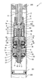
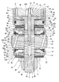
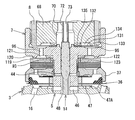
- FIG. 1 is a cross-sectional view of the main part of the shock absorber 1 according to the first embodiment.
- the upper direction (upper side) and the lower direction (lower side) in FIG. 1 are the upper direction (upper side) and the lower direction (lower side) of the shock absorber 1.
- 1st Embodiment is a single cylinder type damping force adjustment type hydraulic shock absorber, it is applicable also to a double cylinder type damping force adjustment type hydraulic shock absorber provided with a reservoir.
- a piston 3 is slidably fitted in the cylinder 2.
- the piston 3 divides the inside of the cylinder 2 into two chambers of an upper cylinder chamber 2A and a lower cylinder chamber 2B.
- a free piston 201 movable in the vertical direction in the cylinder 2 is provided.
- the free piston 201 divides the inside of the cylinder 2 into a cylinder lower chamber 2B on the piston 3 side (upper side) and a gas chamber 202 on the bottom side (lower side).
- oil is sealed as a working fluid.
- the gas chamber 202 high pressure gas is sealed as a working fluid.
- the shaft portion 6 of the piston bolt 5 is inserted into the shaft hole 4 of the piston 3.
- the lower end portion of the substantially cylindrical case member 8 is connected to the upper portion of the substantially cylindrical head 7 of the piston bolt 5 by a screw connection portion 10.
- the piston bolt 5 is formed with an axial hole 50 (common passage) which extends to the tip side (lower side) along the axial direction (vertical direction) and whose upper end opens at the center of the bottom of the head 7.
- the axial hole 50 is formed in an upper portion of the axial hole 50 and is open at the upper end, an axial passage 48 formed in a lower portion of the axial hole 50, and an axial passage It is comprised by the axial direction channel 49 which connects between 30 and 48.
- the diameter (inner diameter) of the axial hole 50 is the largest in diameter of the axial passage 30 and decreases in the order of the axial passage 48 and the axial passage 49.
- the lower end portion of the piston rod 9 is connected to the upper end portion of the case member 8 by a screw connection portion 11.
- the piston rod 9 is inserted into a rod guide 200 attached to the upper end portion of the cylinder 2, and the upper end (the other end) is extended from the cylinder 2 to the outside.
- a nut 12 is screwed into the lower end portion of the piston rod 9, and the nut 12 is brought into contact with the upper end of the case member 8 and tightened, whereby the loosening of the screw connection portion 11 is suppressed.
- a small diameter portion 13 is formed at the lower end of the piston rod 9. In an annular groove formed on the outer peripheral surface of the small diameter portion 13, an O-ring 14 for sealing between the case member 8 and the piston rod 9 is attached.
- the piston 3 is provided with an extension side passage 15 whose one end (upper end) opens to the cylinder upper chamber 2A side and a compression side passage 16 whose one end (lower end) opens to the cylinder lower chamber 2B side.
- the lower end of the piston 3 is provided with an extension damping valve 17 that controls the flow of the working fluid in the extension passage 15.
- a compression side damping valve 18 which controls the flow of the working fluid in the compression side passage 16.
- the expansion side damping valve 17 is fixed to the piston bolt 5 by the expansion side main valve 20 seated on the annular seat portion 19 formed on the outer peripheral side of the lower end face of the piston 3 and the nut 21.
- an extension side back pressure chamber 23 formed between the rear surface of the extension side main valve 20 and the pilot case 22.
- the pressure in the expansion side back pressure chamber 23 acts on the expansion side main valve 20 in the valve closing direction.
- a washer 24, a retainer 25 and a disc valve 26 are provided between the nut 21 and the pilot case 22 in this order from the lower side.
- the inner peripheral edge of the disc valve 26 is sandwiched between the inner peripheral edge of the pilot case 22 and the retainer 25.
- the extension-side main valve 20 is a packing valve in which an annular seal portion 20A made of an elastic body is in contact with the inner peripheral surface of the pilot case 22 over the entire circumference.
- the extension side back pressure chamber 23 is in communication with the lower cylinder chamber 2B via the passage 27 formed in the pilot case 22 and the disc valve 26.
- the extension side back pressure chamber 23 is always in communication with the cylinder lower chamber 2B via an orifice 26A formed in the disk valve 26.
- the disc valve 26 opens when the pressure in the extension side back pressure chamber 23 reaches a predetermined pressure, and relieves the pressure in the extension side back pressure chamber 23 to the cylinder lower chamber 2B.
- the extension side back pressure chamber 23 is in communication with a radial direction passage 29 formed in the piston bolt 5 via a disc type extension side back pressure introduction valve 28.
- the radial passage 29 communicates with an axial passage 30 (common passage) formed in the piston bolt 5.
- the extension side back pressure introduction valve 28 is a check valve that allows only the flow of the working fluid from the radial passage 29 to the extension side back pressure chamber 23.
- the extension-side back pressure introducing valve 28 is seated on an annular seat portion 31 formed on the inner peripheral side of the passage 27 on the upper surface of the pilot case 22.
- the inner peripheral edge portion of the extension-side back pressure introducing valve 28 is sandwiched between the inner peripheral edge portion of the pilot case 22 and the spacer 32.
- the extension-side back pressure chamber 23 communicates with the radial passage 29 through the orifice 28A formed in the extension-side back pressure introduction valve 28 by opening the extension-side back pressure introduction valve 28.
- the axial passage 30 is in communication with a radial passage 33 (a compression side discharge passage) formed in the piston bolt 5.
- the radial passage 33 is in communication with the extension passage 15 via a compression check valve 34 provided in the piston 3.
- the radial passage 33 is always in communication with the extension passage 15 through the orifice 34 A formed in the compression check valve 34.
- the compression check valve 34 only allows the flow of working fluid from the radial passage 33 to the extension passage 15.
- the compression-side damping valve 18 is fixed between the head 7 of the piston bolt 5 and the piston 3 and a compression-side main valve 36 seated on an annular seat 35 formed on the outer peripheral side of the upper end face of the piston 3 And a compression-side back pressure chamber 38 formed between the rear surface of the compression-side main valve 36 and the pilot case 37.
- the pressure in the compression side back pressure chamber 38 acts on the compression side main valve 36 in the valve closing direction.
- the contraction side main valve 36 is a packing valve in which an annular seal portion 36A made of an elastic body is in contact with the inner peripheral surface of the pilot case 37 over the entire circumference.
- the compression side back pressure chamber 38 is in communication with the cylinder upper chamber 2A through the passage 42 formed in the pilot case 37 and the disc valve 41.
- the compression side back pressure chamber 38 is always in communication with the cylinder upper chamber 2A via the orifice 41A formed in the disc valve 41.
- the disc valve 41 opens when the pressure in the compression side back pressure chamber 38 reaches a predetermined pressure, and relieves the pressure in the compression side back pressure chamber 38 to the cylinder upper chamber 2A.
- the compression side back pressure chamber 38 is formed in the piston bolt 5 via the disc type compression side back pressure introducing valve 43 and the circumferential groove 39 formed on the inner peripheral surface of the pilot case 37. It is communicated with.
- the radial passage 44 is in communication with the axial passage 48 (common passage) of the piston bolt 5.
- the compression side back pressure introduction valve 43 is a check valve that allows only the flow of working fluid from the radial passage 44 to the compression side back pressure chamber 38.
- the compression-side back pressure introducing valve 43 is seated on an annular seat portion 45 formed on the inner peripheral side of the passage 42 on the lower surface of the pilot case 37.
- the inner peripheral edge portion of the compression side back pressure introducing valve 43 is sandwiched between the inner peripheral edge portion of the pilot case 37 and the spacer 40.
- the compression side back pressure chamber 38 is communicated with the radial passage 44 through the orifice 43 A formed in the compression side back pressure introduction valve 43 when the compression side back pressure introduction valve 43 is opened.
- the axial passage 48 is in communication with a radial passage 46 (extending side discharge passage) formed in the piston bolt 5.
- the radial passage 46 is in communication with the compression passage 16 via an extension check valve 47 provided in the piston 3.
- the radial passage 46 is always in communication with the compression passage 16 via an orifice 47 A formed in the expansion check valve 47.
- the extension check valve 47 only allows the flow of working fluid from the radial passage 46 to the compression passage 16.
- the flow of the working fluid in the axial hole 50 (common passage) of the piston bolt 5 is controlled by the pilot valve.
- the pilot valve has a valve spool 51 (valve body) slidably fitted in the axial hole 50.
- the valve spool 51 has a solid shaft and constitutes a pilot valve together with the piston bolt 5.
- the valve spool 51 is located in the upper portion of the axial passage 48, in other words, a base 52 slidably fitted on the upper portion of the radial passage 44, and is located in the axial passage 48 via the tapered portion 53.
- Valve portion 54 continuous with the base portion 52, a tip portion 55 (fitting portion) positioned in the axial passage 30 in the valve closing state of the pilot valve (see FIG.
- the diameter (outer diameter) of the valve spool 51 is largest at the base 52 and decreases in the order of the valve portion 54, the tip portion 55, and the connection portion 56. Further, the outer diameter of the valve portion 54 is larger than the inner diameter of the axial passage 49.
- the valve spool 51 is urged upward with respect to the piston bolt 5 by a valve spring 59 interposed between the spring receiving portion 57 of the tip 55 and the spring receiving portion 58 of the piston bolt 5.
- the end face of the base 52 is abutted (pressed) on a rod 72 of a solenoid 71 described later.
- the tip end 55 of the valve spool 51 is formed in a circular shape with a cross section in a plane perpendicular to the axis with a cutout 65 having a two-face width.
- An annular seat portion 63 on which the valve portion 54 of the valve spool 51 is seated is formed at the opening peripheral edge of the upper end (the axial passage 48 side) of the axial passage 49.
- a seating surface 54A formed in a tapered shape is formed on the outer peripheral edge of the lower end (the connection portion 56 side) of the valve portion 54.
- the solenoid 71 has a case member 8, a rod 72 and a coil 74, and a plunger 69 is coupled to the outer peripheral surface of the rod 72.
- the plunger 69 which is also referred to as a movable core, is formed in a substantially cylindrical shape by an iron-based magnetic body.
- the plunger 69 is energized by the coil 74 to generate a magnetic force, thereby generating a thrust.
- the rod 72 is formed in a cylindrical shape, and has an in-rod passage 73 penetrating (extending) the rod 72 in the axial direction (vertical direction).
- the rod 72 is movably supported in the vertical direction (axial direction) by a bush 78 incorporated in the stator core 76.
- the anchor 68 of the solenoid 71 is formed with an axial hole 68A that penetrates the anchor 68 in the axial direction.
- a spool back pressure chamber 70 (chamber) is formed inside the shaft hole 68A.
- the upper end of the valve spool 51 and the lower end of the rod 72 are abutted in the spool back pressure chamber 70 at the upper end (one side end) of the pilot valve.
- the spool back pressure chamber 70 communicates with the cylinder upper chamber 2A via the upper chamber side communication passage when the pilot valve is closed.
- the upper chamber side communication passage extends radially in the notch 75 formed in the tip (lower end) of the rod 72, the in-rod passage 73, the rod back pressure chamber 101 formed in the stator core 76, and the stator core 76
- a passage 102 communicating the rod back pressure chamber 101 with the outer peripheral surface of the stator core 76 and an air vent orifice 103 formed on the side wall of the case member 8 are provided.
- a spool back pressure relief valve 81 check valve
- a retainer 82 a washer 83
- a disc 84 in order from the upper side.
- a retainer 85 and a disc valve 41 are provided.
- the inner peripheral edge of the disc valve 41 is sandwiched between the inner peripheral edge of the pilot case 37 and the retainer 85.
- the outer peripheral surface 83 A of the washer 83 is fitted to the lower inner peripheral surface of the annular wall 7 A of the head 7 of the piston bolt 5.
- An annular groove 87 in which the O-ring 86 is mounted is formed on the outer peripheral surface 83A of the washer.
- the O-ring 86 provides a fluid-tight seal between the washer 83 and the annular wall 7A of the head 7 of the piston bolt 5, in other words, between a circumferential groove 89 described later and the cylinder upper chamber 2A.
- the spool back pressure relief valve 81 has an inner peripheral edge held between the retainer 82 and the inner peripheral edge of the head 7 of the piston bolt 5, and the outer peripheral edge is formed annular on the lower surface of the head 7 of the piston bolt 5.
- the seat portion 88 is seated.
- a circumferential groove 89 is formed between the head 7 of the piston bolt 5 and the washer 83 which is used as a space for opening the spool back pressure relief valve 81.
- the spool back pressure relief valve 81 is a non-return valve that allows only the flow of working fluid from the spool back pressure chamber 70 to the circumferential groove 89.
- the spool back pressure chamber 70 is in communication with the cylinder lower chamber 2B via the lower chamber communication passage (communication passage).
- the lower chamber communication passage has a circumferential groove 104 formed around the valve spool 51 (base 52) between the recess 66 on the lower surface of the anchor 68 and the head 7 of the piston bolt 5.
- the lower chamber side communication passage includes a circumferential groove 95 formed on the upper surface of the head 7 of the piston bolt 5, a circumferential groove 94 formed on the inside of the seat portion 88 on the lower surface of the head 7 of the piston bolt 5, and It has a passage 96 which extends the head 7 of the piston bolt 5 in the vertical direction to allow the circumferential grooves 95 and 94 to communicate with each other.
- the spool back pressure chamber 70 is in communication with the circumferential groove 89 via the circumferential groove 104, the circumferential groove 95, the passage 96, the circumferential groove 94, and the spool back pressure relief valve 81.
- the lower chamber side communication passage (communication passage) is formed on the upper surface of the washer 83 and extends radially outward from the inner peripheral surface of the washer 83, and is formed on the lower surface of the washer 83.
- a groove 92 extending radially outward from the shaft, a passage 91 extending the washer 83 vertically to communicate between the grooves 90 and 92, and an outer peripheral surface of the shaft 6 of the piston bolt 5 are formed on the piston bolt 5 It has a groove 93 for communicating the radial passage 44 with the groove 92.
- the circumferential groove 89 is in communication with the axial passage 48 via the groove 90, the passage 91, the groove 92, the groove 93 and the radial passage 44.
- the groove 93 is formed by processing the width across the shaft 6 of the piston bolt 5.
- the compression stroke of the piston rod 9 (hereinafter referred to as "the compression stroke"), the working fluid in the cylinder lower chamber 2B is received before the contraction side main valve 36 opens, the contraction side passage 16, the expansion side check valve 47 Through the orifice 47A, the radial passage 46, the axial passage 48, the radial passage 44, the compression side back pressure introducing valve 43, the compression side back pressure chamber 38, the passage 42 of the pilot case 37, and the orifice 41A of the disc valve 41. Flow to the cylinder upper chamber 2A.
- the extension stroke of the piston rod 9 (hereinafter referred to as “the extension stroke”), the working fluid in the cylinder upper chamber 2A is generated before the extension side main valve 20 is opened, the extension side passage 15, the compression side check valve 34 34A, radial passage 33, axial passage 30, radial passage 29, extension side back pressure introducing valve 28, extension side back pressure chamber 23, passage 27 of pilot case 22, and orifice 26A of disc valve 26.
- the extension stroke the working fluid in the cylinder upper chamber 2A is generated before the extension side main valve 20 is opened, the extension side passage 15, the compression side check valve 34 34A, radial passage 33, axial passage 30, radial passage 29, extension side back pressure introducing valve 28, extension side back pressure chamber 23, passage 27 of pilot case 22, and orifice 26A of disc valve 26.
- the valve spool 51 (valve body) moves and the valve portion 54 is released from the seat portion 63, that is, when the pilot valve is opened, the working fluid in the cylinder upper chamber 2A is extended by the extension passage 15 Through the orifice 34A of the non-return valve 34, the radial passage 33, the axial passage 30, the axial passage 49, the axial passage 48, the radial passage 46, the extension check valve 47, and the contraction passage 16. Flow to the cylinder lower chamber 2B.
- the valve opening pressure of the pilot valve can be adjusted.
- the pressure of the working fluid introduced from the extension side back pressure introducing valve 28 to the extension side back pressure chamber 23 is also adjusted, so that the opening pressure of the extension side main valve 20 can be controlled.
- the working fluid in the cylinder upper chamber 2A flows into the spool back pressure chamber 70 (chamber) through the upper chamber side communication passage. That is, the working fluid in the cylinder upper chamber 2A is throttled by the air vent orifice 103, and flows into the spool back pressure chamber 70 through the passage 102, the rod back pressure chamber 101, the in-rod passage 73, and the notch 75 of the rod 72. .
- the working fluid that has flowed into the spool back pressure chamber 70 flows to the cylinder lower chamber 2B through the lower chamber side communication passage (communication passage).
- the working fluid that has flowed into the spool back pressure chamber 70 is the circumferential groove 104, the circumferential groove 95, the passage 96, the circumferential groove 94, the spool back pressure relief valve 81 (check valve), the circumferential groove 89, the groove 90 flows through the passage 91, the groove 92, the groove 93, the radial passage 44, the axial passage 48, the radial passage 46, the orifice 47A of the extension check valve 47, and the contraction passage 16 to the cylinder lower chamber 2B .
- the working fluid that has flowed into the spool back pressure chamber 70 (chamber) from the air vent orifice 103 via the in-rod passage 73 during the extension stroke is provided in the lower chamber side communication passage. Since the fluid is circulated to the cylinder lower chamber 2B via the disk type spool back pressure relief valve 81 (check valve), it is possible to obtain a large opening area with a small lift amount of the spool back pressure relief valve 81. The overall length of the bolt 5 and thus the overall length of the shock absorber 1 can be shortened.
- the spool back pressure chamber 70 (chamber) and the cylinder lower chamber 2B are communicated via the lower chamber side communication passage (communication passage), the amount of movement of the valve spool 51 when the pilot valve is opened.
- the volume compensation of the spool back pressure chamber 70 is possible, and the responsiveness of the damping force to the input to the shock absorber 1 can be improved.
- a cylinder (2) in which a working fluid is sealed and a cylinder (2) slidably fitted in the cylinder (2), the cylinder upper chamber (2A) and the cylinder lower chamber ( 2B) and a piston rod (9) having one end connected to the piston (3) and the other end extending outward from the cylinder (2), and an extension provided on the piston (3)
- Extension side back pressure for adjusting the valve opening pressure of the extension side main valve (20) provided in the side passage (15) and the compression side passage (16), the extension side passage (15), and the extension side back pressure Chamber (23), a compression side main valve (36) provided in the compression side passage (16), a compression side back pressure chamber (38) for adjusting the opening pressure of the compression side main valve (36), and an extension side
- a passage (50) a valve body (51) movably provided in the common passage (50), a valve spring (59) biasing the valve body (51) in a valve
- the working fluid in the chamber (70) is circulated to the cylinder lower chamber (2B) via the check valve (81), so when the pilot valve is opened. It is possible to compensate for the volume of the chamber (70) for the movement of the valve body (51). Thus, the valve body (51) can be operated smoothly, and the responsiveness of the pilot valve can be improved.
- the large opening area (flow passage area) is obtained with a small lift amount by the disc-type check valve (81), the pressure loss when the check valve (81) is opened. Can be reduced and pressure in the chamber (70) can be prevented from rising.
- a coil spring type check valve it is possible to shorten the axial length of the pilot valve, and hence the overall length of the shock absorber (1). And the manufacturing cost of the shock absorber (1) can be reduced.
- the communication passage is communicated with the cylinder lower chamber (2B) through the compression side back pressure chamber (38), so that the cylinder upper chamber (2A) and the cylinder lower chamber (2B) are And the compression side back pressure chamber (38). Therefore, during the compression stroke, the working fluid in the compression side back pressure chamber (38) flows to the cylinder upper chamber (2A) via the chamber (70). At this time, by adjusting the flow of the working fluid flowing from the compression side back pressure chamber (38) to the cylinder upper chamber (2A) via the chamber (70), using, for example, an orifice, the compression side back pressure chamber It is possible to adjust the pressure generated in (38), which in turn can adjust the opening pressure of the compression side main valve 36.
- the actuator includes a rod (72) for moving the valve body (51) and a solenoid (71) for controlling the movement of the rod (72), and the rod (72) is used. Since an in-rod passage (73) extending along the axial direction is provided, and the chamber (70) and the cylinder upper chamber (2A) are communicated via the in-rod passage (73), The working fluid of the cylinder upper chamber (2A) flows into the chamber (70) through the in-rod passage (73), but the working fluid flowing into the chamber (70) is the check valve (81) of the communication passage. Flow to the cylinder lower chamber (2B). Thereby, it is possible to prevent the pressure rise in the chamber (70) and to prevent the operation lock due to the hydraulic pressure rise of the pilot valve.
- valve body (51) is constituted by a solid shaft
- the valve is compared with the case of using a valve body consisting of a hollow shaft like the shock absorber of Patent Document 1 mentioned above.
- the shaft portion of the piston bolt to be attached can be reduced in diameter (diameter reduction).
- the clamp diameter on the inner peripheral side of the main valve can be reduced, and the damping force on the soft side (valve opening stiffness) can be reduced.
- a disk-type spool back pressure relief valve 81 (reversed) provided between the head 7 of the piston bolt 5 and the washer 83 fitted to the lower side of the head 7 during the extension stroke.
- the working fluid is made to flow from the spool back pressure chamber 70 (chamber) to the cylinder lower chamber 2B.
- the spool back pressure relief valve 81 check valve
- the head 7 of the piston bolt 5 and the anchor 68 The lip portion 112 of the rubber lip 111 provided therebetween is brought into contact with the inner wall surface 113A of the recess 113 opened on the lower surface of the anchor 68.
- the rubber lip 111 is formed by baking the rubber 115 on the surface of the washer 114.
- the rubber lip 111 is attached to the piston bolt 5 with the shaft hole 116 fitted in a boss portion 117 formed on the inner peripheral side of the upper surface of the head 7 of the piston bolt 5.
- the rubber lip 111 divides the space between the recess 113 of the anchor 68 and the head 7 of the piston bolt 5 into a spool back pressure chamber 70 (chamber) and a circumferential groove 118.
- the circumferential groove 118 is in communication with a circumferential groove 95 provided on the top surface of the head 7 of the piston bolt 5.
- the annular wall 7A of the head 7 of the piston bolt 5 extends in the upper and lower directions from the outer peripheral edge of the disc portion, but in the second embodiment, from the outer peripheral edge of the disc portion It extends only upward.
- a washer 119 is provided between the head 7 of the piston bolt 5 and the pilot case 37. The inner peripheral edge of the washer 119 is clamped by the retainer 85 and the inner peripheral edge of the head 7 of the piston bolt 5. The outer peripheral edge of the washer 119 is in contact with an annular seal portion 120 formed on the lower surface of the head 7 of the piston bolt 5. Thus, a circumferential groove 121 is formed between the head 7 of the piston bolt 5 and the washer 119.
- the working fluid that has flowed into the spool back pressure chamber 70 during the extension stroke flows to the cylinder lower chamber 2B through the lower chamber communication passage (communication passage). That is, the working fluid having flowed into the spool back pressure chamber 70 pushes the lip portion 112 (check valve) of the rubber lip 111 open (that is, the lip portion 112 is separated from the inner wall surface 113A of the recess 113 of the anchor 68).
- the fluid flows into the cylinder lower chamber 2B through the groove 93, the radial passage 44, the axial passage 48, the radial passage 46, the orifice 47A of the extension check valve 47, and the contraction passage 16.
- the washer 119 having a thin plate thickness is used instead of the washer 83 having a thick plate with the O-ring 86 attached and having the vertically extending passage 91 as in the first embodiment.
- the axial length of the piston bolt and thus the overall length of the shock absorber can be shortened.
- the lip portion 112 of the rubber lip 111 provided between the head 7 of the piston bolt 5 and the anchor 68 is used.
- the inner wall surface 113A of the concave portion 113 opened on the lower surface of the anchor 68 was abutted.
- the disk type spool back pressure relief valve 131 (check valve) is disposed between the anchor 68 and the head 7 of the piston bolt 5.
- the inner peripheral edge portion of the spool back pressure relief valve 131 is clamped by the inner peripheral edge portion of the anchor 68 and the retainer 132.
- the outer peripheral edge portion of the spool back pressure relief valve 131 is seated on an annular seat portion 133 formed on the outer peripheral edge portion of the anchor 68.
- a circumferential groove 134 is formed between the inner peripheral edge and the outer peripheral edge of the lower surface of the anchor 68.
- the working fluid that has flowed into the spool back pressure chamber 70 during the extension stroke flows to the cylinder lower chamber 2B through the lower chamber communication passage (communication passage). That is, the working fluid having flowed into the spool back pressure chamber 70 opens the spool back pressure relief valve 131 (check valve) through the radial groove 135 and the circumferential groove 134 formed in the inner peripheral edge portion of the anchor 68.
- the compression side passage 16 to the cylinder lower chamber 2B.
- the washer 119 having a small thickness can be used instead of the washer 83 having a large thickness as in the first embodiment, the axial length of the piston bolt Thus, the overall length of the shock absorber can be shortened.
Landscapes
- Engineering & Computer Science (AREA)
- General Engineering & Computer Science (AREA)
- Mechanical Engineering (AREA)
- Physics & Mathematics (AREA)
- Electromagnetism (AREA)
- Fluid-Damping Devices (AREA)
Abstract
Description
本発明の第1実施形態を添付した図を参照して説明する。
図1は、第1実施形態の緩衝器1の主要部の断面図である。以下の説明において、図1における上方向(上側)および下方向(下側)を、緩衝器1における上方向(上側)および下方向(下側)とする。なお、第1実施形態は、単筒型の減衰力調整式油圧緩衝器であるが、リザーバを備える複筒型の減衰力調整式油圧緩衝器にも適用できる。
ピストンロッド9の縮み行程時(以下「縮み行程時」と称する)には、シリンダ下室2Bの作動流体は、縮み側メインバルブ36の開弁前、縮み側通路16、伸び側逆止弁47のオリフィス47A、径方向通路46、軸方向通路48、径方向通路44、縮み側背圧導入弁43、縮み側背圧室38、パイロットケース37の通路42、およびディスクバルブ41のオリフィス41Aを通ってシリンダ上室2Aへ流れる。
第1実施形態は、作動流体が封入されるシリンダ(2)と、シリンダ(2)内に摺動可能に嵌装され、該シリンダ(2)内をシリンダ上室(2A)とシリンダ下室(2B)とに区画するピストン(3)と、一端がピストン(3)に連結され、他端がシリンダ(2)から外部へ延出されるピストンロッド(9)と、ピストン(3)に設けられる伸び側通路(15)および縮み側通路(16)と、伸び側通路(15)に設けられる伸び側メインバルブ(20)と、伸び側メインバルブ(20)の開弁圧力を調整する伸び側背圧室(23)と、縮み側通路(16)に設けられる縮み側メインバルブ(36)と、縮み側メインバルブ(36)の開弁圧力を調整する縮み側背圧室(38)と、伸び側背圧室(23)と縮み側背圧室(38)とを連通する共通通路(50)と、共通通路(50)内に移動可能に設けられる弁体(51)と、弁体(51)を開弁方向へ付勢する弁ばね(59)と、共通通路(50)内の作動流体の流れを制御するパイロット弁と、弁体(51)の移動を制御するアクチュエータと、を備える緩衝器(1)であって、パイロット弁の一側端に設けられ、シリンダ上室(2A)に連通される室(70)と、室(70)とシリンダ下室(2A)とを連通させる連通路と、伸び行程時に連通路内の作動流体がシリンダ下室(2B)へ流通されるのを許容する逆止弁(81)と、を有する。
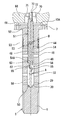
次に、図2および図4を参照して、第2実施形態を主に第1実施形態との相違部分を中心に説明する。なお、第1実施形態と共通する部位については、同一称呼、同一の符号で表す。
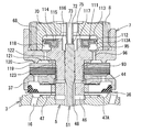
次に、図2、図4および図5を参照して、第3実施形態を主に第2実施形態との相違部分を中心に説明する。なお、第1および第2実施形態と共通する部位については、同一称呼、同一の符号で表す。
Claims (4)
- 緩衝器であって、
作動流体が封入されるシリンダと、
前記シリンダ内に摺動可能に配置され、該シリンダの内部をシリンダ上室とシリンダ下室とに区画するピストンと、
前記ピストンに連結される一端と、前記シリンダから外部へ延出される他端と、を有するピストンロッドと、
前記ピストンに設けられる伸び側通路および縮み側通路と、
前記伸び側通路内に設けられる伸び側メインバルブと、
前記伸び側メインバルブの開弁圧力を調整する伸び側背圧室と、
前記縮み側通路内に設けられる縮み側メインバルブと、
前記縮み側メインバルブの開弁圧力を調整する縮み側背圧室と、
前記伸び側背圧室と前記縮み側背圧室とを連通させる共通通路と、
前記共通通路内に移動可能に設けられる弁体と、
前記弁体を開弁方向へ付勢する弁ばねと、
前記共通通路内の前記作動流体の流れを制御するパイロット弁と、
前記弁体の移動を制御するアクチュエータと、
前記パイロット弁の一側端に設けられ、前記シリンダ上室に連通する室と、
前記室と前記シリンダ下室とを前記縮み側通路を介して連通させる連通路と、
伸び行程時に前記連通路内の前記作動流体が前記シリンダ下室へ流通されるのを許容する逆止弁と、
を備える緩衝器。 - 請求項1に記載の緩衝器であって、
前記連通路は、前記縮み側背圧室を介して前記シリンダ下室に連通する
緩衝器。 - 請求項1または請求項2に記載の緩衝器であって、
前記アクチュエータは、前記弁体を移動させるロッドと、該ロッドの移動を制御するソレノイドと、を備え、
前記ロッドには、軸線方向に沿って延びるロッド内通路が設けられ、
前記室と前記シリンダ上室とは、前記ロッド内通路を介して連通する
緩衝器。 - 請求項1ないし請求項3のいずれか一項に記載の緩衝器であって、
前記弁体は、中実軸である
緩衝器。
Priority Applications (5)
| Application Number | Priority Date | Filing Date | Title |
|---|---|---|---|
| DE112018003806.8T DE112018003806B4 (de) | 2017-07-27 | 2018-07-24 | Stoßdämpfer |
| US16/633,004 US11261932B2 (en) | 2017-07-27 | 2018-07-24 | Shock absorber |
| JP2019532638A JP6808837B2 (ja) | 2017-07-27 | 2018-07-24 | 緩衝器 |
| CN201880023420.8A CN110475985B (zh) | 2017-07-27 | 2018-07-24 | 缓冲器 |
| KR1020197028179A KR102272446B1 (ko) | 2017-07-27 | 2018-07-24 | 완충기 |
Applications Claiming Priority (2)
| Application Number | Priority Date | Filing Date | Title |
|---|---|---|---|
| JP2017-145618 | 2017-07-27 | ||
| JP2017145618 | 2017-07-27 |
Publications (1)
| Publication Number | Publication Date |
|---|---|
| WO2019022075A1 true WO2019022075A1 (ja) | 2019-01-31 |
Family
ID=65041230
Family Applications (1)
| Application Number | Title | Priority Date | Filing Date |
|---|---|---|---|
| PCT/JP2018/027708 Ceased WO2019022075A1 (ja) | 2017-07-27 | 2018-07-24 | 緩衝器 |
Country Status (6)
| Country | Link |
|---|---|
| US (1) | US11261932B2 (ja) |
| JP (2) | JP6808837B2 (ja) |
| KR (1) | KR102272446B1 (ja) |
| CN (1) | CN110475985B (ja) |
| DE (1) | DE112018003806B4 (ja) |
| WO (1) | WO2019022075A1 (ja) |
Cited By (5)
| Publication number | Priority date | Publication date | Assignee | Title |
|---|---|---|---|---|
| JP2020169700A (ja) * | 2019-04-04 | 2020-10-15 | 日立オートモティブシステムズ株式会社 | 緩衝器 |
| JP2021021436A (ja) * | 2019-07-26 | 2021-02-18 | 日立オートモティブシステムズ株式会社 | 減衰力調整式緩衝器 |
| JPWO2021149718A1 (ja) * | 2020-01-24 | 2021-07-29 | ||
| CN117108676A (zh) * | 2023-08-31 | 2023-11-24 | 蜂巢传动系统(江苏)有限公司 | 复合阀和减振器 |
| US12385545B2 (en) * | 2022-03-18 | 2025-08-12 | Beijingwest Industries Co., Ltd. | Damper assembly with frequency adaptive orifice |
Families Citing this family (7)
| Publication number | Priority date | Publication date | Assignee | Title |
|---|---|---|---|---|
| JP6700436B2 (ja) * | 2017-01-18 | 2020-05-27 | 日立オートモティブシステムズ株式会社 | 緩衝器 |
| US11204074B2 (en) * | 2017-09-05 | 2021-12-21 | Hitachi Astemo, Ltd. | Shock absorber |
| JP7112356B2 (ja) * | 2019-03-04 | 2022-08-03 | Kyb株式会社 | 緩衝器 |
| CN110258592B (zh) * | 2019-06-21 | 2021-04-16 | 重庆科技学院 | 自适应泄压式阻尼滑坡防护装置 |
| CN116209840A (zh) * | 2020-10-21 | 2023-06-02 | 日立安斯泰莫株式会社 | 缓冲器 |
| DE112022001839T5 (de) * | 2021-03-29 | 2024-02-15 | Hitachi Astemo, Ltd. | Stoßdämpfer und Ventilvorrichtung |
| CN118564590A (zh) * | 2023-02-28 | 2024-08-30 | 比亚迪股份有限公司 | 用于减振器的流量调节阀、减振器以及车辆 |
Citations (4)
| Publication number | Priority date | Publication date | Assignee | Title |
|---|---|---|---|---|
| JPH05231462A (ja) * | 1992-02-20 | 1993-09-07 | Tokico Ltd | 減衰力調整式油圧緩衝器 |
| JP2007309409A (ja) * | 2006-05-18 | 2007-11-29 | Hitachi Ltd | 油圧緩衝器 |
| JP2008249107A (ja) * | 2007-03-30 | 2008-10-16 | Hitachi Ltd | 減衰力調整式流体圧緩衝器 |
| JP2010038348A (ja) * | 2008-08-08 | 2010-02-18 | Hitachi Automotive Systems Ltd | 減衰力調整式緩衝器 |
Family Cites Families (15)
| Publication number | Priority date | Publication date | Assignee | Title |
|---|---|---|---|---|
| JP2008138757A (ja) | 2006-11-30 | 2008-06-19 | Hitachi Ltd | 減衰力調整式油圧緩衝器 |
| JP4919045B2 (ja) * | 2007-04-19 | 2012-04-18 | 日立オートモティブシステムズ株式会社 | 減衰力調整式流体圧緩衝器 |
| JP4967091B2 (ja) * | 2007-04-19 | 2012-07-04 | 日立オートモティブシステムズ株式会社 | 流体圧緩衝器 |
| US8794403B2 (en) * | 2008-02-13 | 2014-08-05 | Kayaba Industry Co., Ltd. | Damping force generating mechanism for hydraulic shock absorber |
| CN101392810B (zh) * | 2008-11-05 | 2010-08-25 | 北京理工大学 | 油气悬架外置可调阻尼阀 |
| KR101218838B1 (ko) * | 2010-09-08 | 2013-01-07 | 주식회사 만도 | 쇽업소버의 밸브 구조 |
| CN103443500B (zh) * | 2011-03-22 | 2016-01-20 | 萱场工业株式会社 | 阻尼阀 |
| RU2570243C1 (ru) * | 2011-11-30 | 2015-12-10 | Хитачи Отомотив Системз, Лтд. | Амортизатор |
| JP2015068428A (ja) * | 2013-09-30 | 2015-04-13 | 日立オートモティブシステムズ株式会社 | シリンダ装置及びその製造方法 |
| JP6239921B2 (ja) * | 2013-10-03 | 2017-11-29 | Kyb株式会社 | 液圧緩衝器 |
| JP6378618B2 (ja) | 2014-11-25 | 2018-08-22 | Kyb株式会社 | 減衰バルブ及び緩衝器 |
| WO2017090492A1 (ja) * | 2015-11-26 | 2017-06-01 | 日立オートモティブシステムズ株式会社 | 減衰力調整式緩衝器 |
| JP6670627B2 (ja) | 2016-02-17 | 2020-03-25 | 能美防災株式会社 | 固定リング |
| CN106509991B (zh) * | 2016-10-18 | 2018-11-13 | 云南中烟工业有限责任公司 | 一种滑动式开盖装置 |
| US11204074B2 (en) * | 2017-09-05 | 2021-12-21 | Hitachi Astemo, Ltd. | Shock absorber |
-
2018
- 2018-07-24 KR KR1020197028179A patent/KR102272446B1/ko active Active
- 2018-07-24 WO PCT/JP2018/027708 patent/WO2019022075A1/ja not_active Ceased
- 2018-07-24 JP JP2019532638A patent/JP6808837B2/ja active Active
- 2018-07-24 DE DE112018003806.8T patent/DE112018003806B4/de active Active
- 2018-07-24 US US16/633,004 patent/US11261932B2/en active Active
- 2018-07-24 CN CN201880023420.8A patent/CN110475985B/zh active Active
-
2020
- 2020-12-08 JP JP2020203402A patent/JP7182592B2/ja active Active
Patent Citations (4)
| Publication number | Priority date | Publication date | Assignee | Title |
|---|---|---|---|---|
| JPH05231462A (ja) * | 1992-02-20 | 1993-09-07 | Tokico Ltd | 減衰力調整式油圧緩衝器 |
| JP2007309409A (ja) * | 2006-05-18 | 2007-11-29 | Hitachi Ltd | 油圧緩衝器 |
| JP2008249107A (ja) * | 2007-03-30 | 2008-10-16 | Hitachi Ltd | 減衰力調整式流体圧緩衝器 |
| JP2010038348A (ja) * | 2008-08-08 | 2010-02-18 | Hitachi Automotive Systems Ltd | 減衰力調整式緩衝器 |
Cited By (9)
| Publication number | Priority date | Publication date | Assignee | Title |
|---|---|---|---|---|
| JP2020169700A (ja) * | 2019-04-04 | 2020-10-15 | 日立オートモティブシステムズ株式会社 | 緩衝器 |
| JP7171495B2 (ja) | 2019-04-04 | 2022-11-15 | 日立Astemo株式会社 | 緩衝器 |
| JP2021021436A (ja) * | 2019-07-26 | 2021-02-18 | 日立オートモティブシステムズ株式会社 | 減衰力調整式緩衝器 |
| JP7213161B2 (ja) | 2019-07-26 | 2023-01-26 | 日立Astemo株式会社 | 減衰力調整式緩衝器 |
| JPWO2021149718A1 (ja) * | 2020-01-24 | 2021-07-29 | ||
| WO2021149718A1 (ja) * | 2020-01-24 | 2021-07-29 | 日立Astemo株式会社 | 緩衝器 |
| JP7223883B2 (ja) | 2020-01-24 | 2023-02-16 | 日立Astemo株式会社 | 緩衝器 |
| US12385545B2 (en) * | 2022-03-18 | 2025-08-12 | Beijingwest Industries Co., Ltd. | Damper assembly with frequency adaptive orifice |
| CN117108676A (zh) * | 2023-08-31 | 2023-11-24 | 蜂巢传动系统(江苏)有限公司 | 复合阀和减振器 |
Also Published As
| Publication number | Publication date |
|---|---|
| JP7182592B2 (ja) | 2022-12-02 |
| DE112018003806T5 (de) | 2020-06-04 |
| JPWO2019022075A1 (ja) | 2020-02-06 |
| JP2021046944A (ja) | 2021-03-25 |
| CN110475985B (zh) | 2021-04-16 |
| JP6808837B2 (ja) | 2021-01-06 |
| KR20190121826A (ko) | 2019-10-28 |
| US11261932B2 (en) | 2022-03-01 |
| DE112018003806B4 (de) | 2022-06-23 |
| US20200166097A1 (en) | 2020-05-28 |
| CN110475985A (zh) | 2019-11-19 |
| KR102272446B1 (ko) | 2021-07-01 |
Similar Documents
| Publication | Publication Date | Title |
|---|---|---|
| JP7182592B2 (ja) | 緩衝器 | |
| JP7182656B2 (ja) | 緩衝器に用いられる機構 | |
| JP5648790B2 (ja) | 緩衝器 | |
| JP6537628B2 (ja) | 減衰力調整式緩衝器 | |
| KR102223705B1 (ko) | 완충기 | |
| KR20110073234A (ko) | 완충기 | |
| KR20160026753A (ko) | 완충기 | |
| KR102800134B1 (ko) | 완충기 | |
| WO2021020192A1 (ja) | 減衰力調整式緩衝器 | |
| JP2021021438A (ja) | 減衰力調整式緩衝器 | |
| JPWO2020149224A1 (ja) | 緩衝器 | |
| KR102627961B1 (ko) | 감쇠력 조정식 완충기 | |
| JP7171495B2 (ja) | 緩衝器 | |
| JP7223883B2 (ja) | 緩衝器 | |
| JP7213161B2 (ja) | 減衰力調整式緩衝器 | |
| WO2022075011A1 (ja) | 緩衝器 | |
| JP2016070421A (ja) | 緩衝器 | |
| KR102855080B1 (ko) | 감쇠력 조정식 완충기, 감쇠 밸브 및 솔레노이드 | |
| WO2018180434A1 (ja) | 減衰力調整式緩衝器 | |
| JP2015068479A (ja) | 減衰力調整式緩衝器 |
Legal Events
| Date | Code | Title | Description |
|---|---|---|---|
| 121 | Ep: the epo has been informed by wipo that ep was designated in this application |
Ref document number: 18838983 Country of ref document: EP Kind code of ref document: A1 |
|
| ENP | Entry into the national phase |
Ref document number: 2019532638 Country of ref document: JP Kind code of ref document: A |
|
| ENP | Entry into the national phase |
Ref document number: 20197028179 Country of ref document: KR Kind code of ref document: A |
|
| 122 | Ep: pct application non-entry in european phase |
Ref document number: 18838983 Country of ref document: EP Kind code of ref document: A1 |