WO2019021880A1 - Bloc-batterie et son procédé de fabrication - Google Patents
Bloc-batterie et son procédé de fabrication Download PDFInfo
- Publication number
- WO2019021880A1 WO2019021880A1 PCT/JP2018/026690 JP2018026690W WO2019021880A1 WO 2019021880 A1 WO2019021880 A1 WO 2019021880A1 JP 2018026690 W JP2018026690 W JP 2018026690W WO 2019021880 A1 WO2019021880 A1 WO 2019021880A1
- Authority
- WO
- WIPO (PCT)
- Prior art keywords
- secondary battery
- battery
- battery pack
- cell
- cylindrical
- Prior art date
Links
Images


Classifications
-
- H—ELECTRICITY
- H01—ELECTRIC ELEMENTS
- H01M—PROCESSES OR MEANS, e.g. BATTERIES, FOR THE DIRECT CONVERSION OF CHEMICAL ENERGY INTO ELECTRICAL ENERGY
- H01M10/00—Secondary cells; Manufacture thereof
- H01M10/60—Heating or cooling; Temperature control
- H01M10/64—Heating or cooling; Temperature control characterised by the shape of the cells
- H01M10/643—Cylindrical cells
-
- H—ELECTRICITY
- H01—ELECTRIC ELEMENTS
- H01M—PROCESSES OR MEANS, e.g. BATTERIES, FOR THE DIRECT CONVERSION OF CHEMICAL ENERGY INTO ELECTRICAL ENERGY
- H01M10/00—Secondary cells; Manufacture thereof
- H01M10/60—Heating or cooling; Temperature control
- H01M10/65—Means for temperature control structurally associated with the cells
- H01M10/659—Means for temperature control structurally associated with the cells by heat storage or buffering, e.g. heat capacity or liquid-solid phase changes or transition
-
- H—ELECTRICITY
- H01—ELECTRIC ELEMENTS
- H01M—PROCESSES OR MEANS, e.g. BATTERIES, FOR THE DIRECT CONVERSION OF CHEMICAL ENERGY INTO ELECTRICAL ENERGY
- H01M10/00—Secondary cells; Manufacture thereof
- H01M10/60—Heating or cooling; Temperature control
- H01M10/61—Types of temperature control
- H01M10/613—Cooling or keeping cold
-
- H—ELECTRICITY
- H01—ELECTRIC ELEMENTS
- H01M—PROCESSES OR MEANS, e.g. BATTERIES, FOR THE DIRECT CONVERSION OF CHEMICAL ENERGY INTO ELECTRICAL ENERGY
- H01M10/00—Secondary cells; Manufacture thereof
- H01M10/60—Heating or cooling; Temperature control
- H01M10/65—Means for temperature control structurally associated with the cells
- H01M10/653—Means for temperature control structurally associated with the cells characterised by electrically insulating or thermally conductive materials
-
- H—ELECTRICITY
- H01—ELECTRIC ELEMENTS
- H01M—PROCESSES OR MEANS, e.g. BATTERIES, FOR THE DIRECT CONVERSION OF CHEMICAL ENERGY INTO ELECTRICAL ENERGY
- H01M10/00—Secondary cells; Manufacture thereof
- H01M10/60—Heating or cooling; Temperature control
- H01M10/65—Means for temperature control structurally associated with the cells
- H01M10/655—Solid structures for heat exchange or heat conduction
-
- H—ELECTRICITY
- H01—ELECTRIC ELEMENTS
- H01M—PROCESSES OR MEANS, e.g. BATTERIES, FOR THE DIRECT CONVERSION OF CHEMICAL ENERGY INTO ELECTRICAL ENERGY
- H01M50/00—Constructional details or processes of manufacture of the non-active parts of electrochemical cells other than fuel cells, e.g. hybrid cells
- H01M50/20—Mountings; Secondary casings or frames; Racks, modules or packs; Suspension devices; Shock absorbers; Transport or carrying devices; Holders
- H01M50/204—Racks, modules or packs for multiple batteries or multiple cells
- H01M50/207—Racks, modules or packs for multiple batteries or multiple cells characterised by their shape
- H01M50/213—Racks, modules or packs for multiple batteries or multiple cells characterised by their shape adapted for cells having curved cross-section, e.g. round or elliptic
-
- H—ELECTRICITY
- H01—ELECTRIC ELEMENTS
- H01M—PROCESSES OR MEANS, e.g. BATTERIES, FOR THE DIRECT CONVERSION OF CHEMICAL ENERGY INTO ELECTRICAL ENERGY
- H01M50/00—Constructional details or processes of manufacture of the non-active parts of electrochemical cells other than fuel cells, e.g. hybrid cells
- H01M50/20—Mountings; Secondary casings or frames; Racks, modules or packs; Suspension devices; Shock absorbers; Transport or carrying devices; Holders
- H01M50/233—Mountings; Secondary casings or frames; Racks, modules or packs; Suspension devices; Shock absorbers; Transport or carrying devices; Holders characterised by physical properties of casings or racks, e.g. dimensions
- H01M50/24—Mountings; Secondary casings or frames; Racks, modules or packs; Suspension devices; Shock absorbers; Transport or carrying devices; Holders characterised by physical properties of casings or racks, e.g. dimensions adapted for protecting batteries from their environment, e.g. from corrosion
-
- H—ELECTRICITY
- H01—ELECTRIC ELEMENTS
- H01M—PROCESSES OR MEANS, e.g. BATTERIES, FOR THE DIRECT CONVERSION OF CHEMICAL ENERGY INTO ELECTRICAL ENERGY
- H01M50/00—Constructional details or processes of manufacture of the non-active parts of electrochemical cells other than fuel cells, e.g. hybrid cells
- H01M50/20—Mountings; Secondary casings or frames; Racks, modules or packs; Suspension devices; Shock absorbers; Transport or carrying devices; Holders
- H01M50/289—Mountings; Secondary casings or frames; Racks, modules or packs; Suspension devices; Shock absorbers; Transport or carrying devices; Holders characterised by spacing elements or positioning means within frames, racks or packs
- H01M50/291—Mountings; Secondary casings or frames; Racks, modules or packs; Suspension devices; Shock absorbers; Transport or carrying devices; Holders characterised by spacing elements or positioning means within frames, racks or packs characterised by their shape
-
- H—ELECTRICITY
- H01—ELECTRIC ELEMENTS
- H01M—PROCESSES OR MEANS, e.g. BATTERIES, FOR THE DIRECT CONVERSION OF CHEMICAL ENERGY INTO ELECTRICAL ENERGY
- H01M50/00—Constructional details or processes of manufacture of the non-active parts of electrochemical cells other than fuel cells, e.g. hybrid cells
- H01M50/20—Mountings; Secondary casings or frames; Racks, modules or packs; Suspension devices; Shock absorbers; Transport or carrying devices; Holders
- H01M50/289—Mountings; Secondary casings or frames; Racks, modules or packs; Suspension devices; Shock absorbers; Transport or carrying devices; Holders characterised by spacing elements or positioning means within frames, racks or packs
- H01M50/293—Mountings; Secondary casings or frames; Racks, modules or packs; Suspension devices; Shock absorbers; Transport or carrying devices; Holders characterised by spacing elements or positioning means within frames, racks or packs characterised by the material
-
- H—ELECTRICITY
- H01—ELECTRIC ELEMENTS
- H01M—PROCESSES OR MEANS, e.g. BATTERIES, FOR THE DIRECT CONVERSION OF CHEMICAL ENERGY INTO ELECTRICAL ENERGY
- H01M10/00—Secondary cells; Manufacture thereof
- H01M10/60—Heating or cooling; Temperature control
- H01M10/62—Heating or cooling; Temperature control specially adapted for specific applications
- H01M10/623—Portable devices, e.g. mobile telephones, cameras or pacemakers
- H01M10/6235—Power tools
-
- H—ELECTRICITY
- H01—ELECTRIC ELEMENTS
- H01M—PROCESSES OR MEANS, e.g. BATTERIES, FOR THE DIRECT CONVERSION OF CHEMICAL ENERGY INTO ELECTRICAL ENERGY
- H01M10/00—Secondary cells; Manufacture thereof
- H01M10/60—Heating or cooling; Temperature control
- H01M10/62—Heating or cooling; Temperature control specially adapted for specific applications
- H01M10/625—Vehicles
-
- H—ELECTRICITY
- H01—ELECTRIC ELEMENTS
- H01M—PROCESSES OR MEANS, e.g. BATTERIES, FOR THE DIRECT CONVERSION OF CHEMICAL ENERGY INTO ELECTRICAL ENERGY
- H01M10/00—Secondary cells; Manufacture thereof
- H01M10/60—Heating or cooling; Temperature control
- H01M10/62—Heating or cooling; Temperature control specially adapted for specific applications
- H01M10/627—Stationary installations, e.g. power plant buffering or backup power supplies
-
- Y—GENERAL TAGGING OF NEW TECHNOLOGICAL DEVELOPMENTS; GENERAL TAGGING OF CROSS-SECTIONAL TECHNOLOGIES SPANNING OVER SEVERAL SECTIONS OF THE IPC; TECHNICAL SUBJECTS COVERED BY FORMER USPC CROSS-REFERENCE ART COLLECTIONS [XRACs] AND DIGESTS
- Y02—TECHNOLOGIES OR APPLICATIONS FOR MITIGATION OR ADAPTATION AGAINST CLIMATE CHANGE
- Y02E—REDUCTION OF GREENHOUSE GAS [GHG] EMISSIONS, RELATED TO ENERGY GENERATION, TRANSMISSION OR DISTRIBUTION
- Y02E60/00—Enabling technologies; Technologies with a potential or indirect contribution to GHG emissions mitigation
- Y02E60/10—Energy storage using batteries
Definitions
- the present invention relates to a battery pack and a method of manufacturing the same.
- the battery pack is widely used as a power source for an electric power tool, an electric assist bicycle, an electric motorcycle, a hybrid electric car, an electric car and the like, and further for storage of electricity in homes and stores.
- a battery pack can be charged and discharged by connecting a plurality of rechargeable secondary battery cells in series or in parallel.
- a battery assembly 80 in which a plurality of battery cells 81 are housed in a battery holder 82 is housed in a waterproof container 83, and this waterproof container 83 is housed in an outer case 84 as a battery core pack.
- the battery holder 82 makes the plurality of battery cells 81 parallel to each other, arranges the electrode terminals provided at both ends of each battery cell 81 on the same surface, and at both side surfaces of the battery holder 82, The electrode terminals are connected by a lead plate 85.
- potting resin is filled in a state where the battery assembly 80 is housed in a bag-like waterproof container 83.
- the potting resin is made of urethane resin or the like, and the space between the secondary battery cells is filled to achieve soaking, and even if the temperature of one secondary battery cell rises, the other secondary through the potting resin By conducting heat to a battery cell or the like, it is possible to suppress a local temperature rise.
- the present invention has been made in view of such a background, and one of the objects thereof is a battery pack capable of adding a function of suppressing the temperature rise of the secondary battery cell by a simple method, and a method of manufacturing the same To provide.
- a battery assembly formed by storing one or more secondary battery cells in a battery holder holding the secondary battery cells, and the secondary battery cell It is possible to provide a pre-formed flexible heat dissipating molded product that can be melted by the heat generation of the secondary battery cell, which covers the surface, and an outer case that accommodates the battery assembly.
- the said thermal radiation molded object can be comprised with the material which shows the chemical reaction fuse
- the secondary battery cell has a cylindrical appearance
- the heat dissipation molded body is a cylindrical shape of the secondary battery cell. It can be formed into a shape along the curved surface of the side surface. According to the above configuration, the heat dissipating molded body can be disposed along the side surface of the cylindrical secondary battery cell.
- the battery assembly holds the plurality of secondary battery cells in a posture adjacent to one another by the battery holder.
- the heat radiation molded body can be disposed so as to straddle the adjacent secondary battery cell.
- a plurality of secondary battery cells can be covered with one heat dissipating molded body to dissipate heat.
- the secondary battery cell has a cylindrical shape in appearance
- the battery holder is an end portion of the secondary battery cell
- the heat dissipating molded product can cover the side surface of the secondary battery cell exposed from the cell holding portion. According to the above configuration, while the secondary battery cell is held by the battery holder, it is possible to cover the partially exposed cylindrical side surface with the heat dissipating molded body to dissipate the heat.
- the surface of the secondary battery cell held by the battery holder by dividing the heat-radiating molded body into a plurality of pieces Each can be configured to coat.
- the secondary battery cell has a cylindrical outer shape, and the battery holder is adjacent to a plurality of secondary battery cells.
- the heat dissipating molded body may be formed in an annular shape covering the side surface of the secondary battery cell positioned around the periphery of the plurality of secondary battery cells held by the battery holder .
- the battery holder includes a molded body pressing portion that presses the heat dissipating molded body against the surface of the secondary battery cell.
- the heat-radiating molded body can be pressed against the surface of the secondary battery cell without using an adhesive to be in a thermally coupled state.
- the said thermal radiation molded object can be comprised with the material containing a urethane resin or a silicone resin.
- the above-mentioned thermal radiation molded object can be constituted by the material containing the filler which carries out endothermic reaction. According to the above configuration, since the heat radiation molded body partially melts the contact portion with the secondary battery cell due to the heat generation of the secondary battery cell, the heat radiation molded body can be closely adhered without using an adhesive or the like. It is possible to easily obtain a thermally coupled state excellent in heat conduction by reducing the gap serving as the heat insulating layer.
- the battery pack further includes a waterproof container for housing the battery assembly, and the battery assembly is housed in the waterproof container. It can be stored in the outer case. With the above configuration, it is possible to waterproof the battery assembly.
- a battery assembly formed by storing a plurality of cylindrical secondary battery cells in a pair of battery holders holding the cylindrical secondary battery cells.
- a method of manufacturing a battery pack comprising: an outer case for housing the battery assembly, wherein the surface of the cylindrical secondary battery cell is covered, wherein the cylindrical secondary battery cell is meltable by heat generation. And a step of preparing a molded heat dissipating molded product having flexibility, and one end of the cylindrical secondary battery cell being a cylindrical cell holding portion of one of the pair of battery holders.
- a step of inserting in the second step a step of covering the side surface of the cylindrical secondary battery cell exposed from the cell holding portion with the heat dissipation molded body, and the other end of the cylindrical secondary battery cell as the pair Of the other battery holders It may include a step of inserting the cell holding part of the tubular.
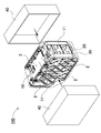
- FIG. 7A to 7E are exploded perspective views showing manufacturing steps of the battery pack according to the second embodiment. It is an exploded perspective view showing a conventional battery pack.
- each element constituting the present invention may be configured such that a plurality of elements are constituted by the same member and one member is used in common as a plurality of elements, or conversely, the function of one member is realized by a plurality of members It can be shared and realized. (Embodiment 1)
- FIG. 1 is a perspective view showing a battery pack 100 according to Embodiment 1 of the present invention
- FIG. 2 is an exploded perspective view of the battery pack 100 of FIG. 1
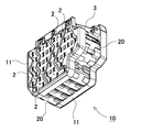
- FIG. 3 is a battery assembly 10 of FIG. 4 is a perspective view of the battery assembly 10 of FIG. 3 viewed from the bottom side
- FIG. 5 is an exploded perspective view of the battery assembly 10 of FIG. 3
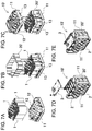
- FIG. FIGS. 7A to 7E are exploded perspective views showing manufacturing steps of the battery pack according to the second embodiment, respectively.
- the battery pack 100 shown in FIG. 1 is configured by a box-shaped outer case 40 in an outer shape.
- the exterior case 40 is divided into two as shown in FIG. 2, and a storage space is provided inside.
- the battery assembly 10 is housed in a storage space inside the exterior case 40.
- the outer case 40 is made of a lightweight material having excellent insulation, such as resin.
- the battery assembly 10 exhibits waterproofness by being accommodated in a waterproof container.
- the waterproof container 30 is covered with a waterproof bag 30 as an example of the waterproof container, and has a waterproof property.
- the waterproof bag 30 is made of transparent resin and, for example, polyethylene can be used. In the case where the waterproof function is not provided, the waterproof bag may be omitted.
- the battery assembly 10 has a box shape whose outer shape is partially bounded. As shown in the exploded perspective view of FIG. 5, the battery assembly 10 accommodates a plurality of secondary battery cells 1 in a battery holder 11.
- the battery holder 11 is divided into two on the left and right sides, and held so as to sandwich each of the secondary battery cells 1 from both sides.
- the battery holders 11 are fixed, for example, by screwing, fitting, welding or the like.
- Each battery holder 11 forms a cylindrical cell holding portion 12 for holding an end portion of the secondary battery cell 1 respectively. Further, in a state where the secondary battery cell 1 is set in the battery holder 11, the end face of the secondary battery cell 1 is exposed from the battery holder 11 and welded to the lead plate 2.
- the secondary battery cell 1 is a cylindrical battery having a cylindrical outer can.
- a lithium ion secondary battery, a nickel hydrogen secondary battery, a nickel cadmium secondary battery, etc. can be used.
- a lithium ion secondary battery excellent in energy efficiency per unit volume is preferable.
- a plurality of secondary battery cells 1 are connected in series or in parallel by connecting the electrodes of the end faces with a lead plate 2. In the example of FIG. 5, 35 secondary battery cells 1 are connected by 5 parallels 7 directs. In accordance with this, the shape and the arrangement of the lead plate 2 are determined.
- the lead plate 2 is made of a metal having excellent conductivity.
- the lead plate 2 is connected to the end face of the secondary battery cell 1 by spot welding or the like. Furthermore, the lead plate 2 is connected to the circuit board 3.
- the circuit board 3 is disposed on one surface of the battery holder 11.
- the charge and discharge circuit and the protection circuit of the secondary battery cell 1 are mounted on the circuit board 3. (Thermal radiation molded body 20)
- a heat dissipating molded body 20 is disposed on the surface of the secondary battery cell 1.
- the heat dissipating molded body 20 is a plate-shaped member that has been molded in advance, and is curved according to the shape of the outer can of the secondary battery cell 1. Further, the heat dissipating molded body 20 is formed of a material which has flexibility and is melted by the heat generation of the secondary battery cell 1.
- the temperature tends to be higher in the secondary battery cells located in the periphery than in the middle secondary battery cells.
- the secondary battery cell positioned in the middle even if the temperature rises, it is easily thermally conducted to the secondary battery cells present in the periphery, and as a result, an endothermic effect is exhibited. It is possible to suppress a situation where the temperature of only the next battery cell becomes high.
- the secondary battery cells arranged in the peripheral part since the number of secondary batteries existing in the periphery is small, there is no escape place for heat even if the temperature rises, and as a result, the function to suppress the temperature rise Hard to get.
- the battery assembly is housed in a waterproof bag, and potting resin is injected into the inside and sealed, whereby the potting resin to be injected is brought into close contact with the secondary battery cell in a thermally coupled state and heat is generated. It has been done to improve the conductivity.
- the heat dissipation molded body 20 excellent in thermal conductivity is molded in advance, and the secondary battery cell is assembled at the time of assembly.
- the heat dissipation of the secondary battery cell 1 located around the battery assembly 10 is improved.
- this method it is possible to provide heat dissipation to an arbitrary part by arranging the heat dissipating molded body 20 at a necessary part, as compared to the method of potting the entire battery assembly 10.
- weight reduction is achieved.
- the pre-formed, tangible heat-dissipation molded body 20 can be disposed around the secondary battery cell 1, the manufacturing process can be greatly simplified as compared with the operation of injecting and curing the liquid potting resin.
- the heat dissipating molded body 20 is formed in advance in a shape along the outer shape of the secondary battery cell 1 so as to be easily in close contact with the periphery of the secondary battery cell 1. Furthermore, by using a flexible material, it can be easily deformed according to the actual shape of the secondary battery cell 1 to absorb manufacturing tolerances of the outer can, errors during assembly, etc. Is taken.
- the cylindrical secondary battery cells 1 are held by the battery holder 11 in a state in which the side surfaces are arranged adjacent to each other.
- the battery holder 11 inserts and holds a part of the end face of the cylindrical secondary battery cell 1 in the cell holding portion 12, and exposes the intermediate portion of the outer can from the battery holder 11. Therefore, the heat radiation molded body 20 is disposed at this exposed portion. (Molded body pressing portion 13)
- the heat dissipating molded body 20 is joined to at least a part of the side surface of the secondary battery cell 1 in a thermally coupled state.
- the heat dissipating molded body 20 is bonded to the side surface of the secondary battery cell 1 with an adhesive or an adhesive such as a double-sided tape, or the heat dissipating molded body 20 is physically pressed to the surface of the secondary battery cell 1
- the body pressing portion 13 may be provided on the battery holder 11. In the example of the battery holder 11 shown in the enlarged cross sectional views of FIG. 5 and FIG.
- a rib is formed as a molded body pressing portion 13 in a portion where the outer can of the secondary battery cell 1 is exposed from the battery holder 11
- the heat dissipating molded body 20 is press-fitted between the secondary battery cell 1 and the rib.
- the ribs are formed in a shape that conforms to the outer shape of the heat dissipating molded body 20.
- the rib is substantially parallel to the cell holding portion 12 and is separated from the surface of the secondary battery cell 1 inserted in the cell holding portion 12 by the thickness of the heat dissipating molded body 20 or a slightly narrower interval than this. And protrudes along the extension direction of the cell holding portion 12.
- the ribs do not necessarily have to be provided over the entire surface of the heat radiation molded body 20, and can be partially formed so as to press a part of the heat radiation molded body 20.
- the rib is provided in the position of the trough which made cylindrical secondary battery cell 1 comrades adjoin.
- the rib may be formed into a wall shape or may be a rod shape, or any other configuration capable of holding the heat dissipating molded product can be appropriately used.
- the contact surface of the heat dissipating molded article 20 may be melted and brought into close contact by the heat generation of the secondary battery cell 1.
- the radiation molded body 20 can be brought into close contact with the secondary battery cell 1 without using an adhesive, and a gap is formed between the surface of the outer can and the radiation molded body 20. It is possible to prevent the heat conduction from being hindered by the heat insulation effect of the air layer.
- the heat dissipating molded body 20 uses a resin having high thermal conductivity and heat absorption.
- the urethane resin used by the conventional potting resin can be utilized suitably. By using such a material, heat absorption can be exhibited by the heat capacity of the heat radiation molded body itself.
- the urethane resin material containing the filler component which carries out endothermic reaction in a high temperature range can be used suitably.
- the filler component that reacts endothermicly in the high temperature region exhibits a further heat radiation suppression effect.
- the heat dissipating molded body 20 is disposed so as to straddle the adjacent secondary battery cells 1.
- the adjacent secondary battery cells can be thermally coupled, and even if one secondary battery cell generates heat, another secondary battery cell can be configured to absorb part of the generated heat. That is, the heat conductivity of some secondary battery cells is absorbed by the surrounding secondary battery cells by increasing the thermal conductivity instead of thermally insulating between adjacent secondary battery cells. It becomes possible to suppress runaway.
- each secondary battery cell is not covered with the heat dissipating molded body, but the exposed surface of the secondary battery cells positioned on the outer periphery in the state where the secondary battery cells 1 are stacked is a heat dissipating molded body It has composition covered by 20.
- the thermal conductivity of the secondary battery cells located on the outer periphery is reduced by the amount that the secondary battery cells are not adjacent to the periphery, only the region where the secondary battery cells are not adjacent is covered with the heat dissipation molded body 20 By enhancing the thermal conductivity, the same thermal conductivity as that of the secondary battery cell positioned in the middle of the battery assembly 10 can be exhibited.
- the present invention is not limited to the configuration in which only the region exposed from the battery stack among the secondary battery cells constituting the battery stack is covered with the heat dissipating molded product, for example, secondary battery cells
- the heat dissipating molded body may be interposed between the As a result, the thermal conductivity can be further enhanced also in the middle portion, and the effect of suppressing thermal runaway of some of the secondary battery cells is exhibited.
- the heat dissipating molded body 20 is divided into a plurality of parts as shown in FIG. 5 and arranged around the stacked secondary battery cells 1 respectively. By dividing the heat dissipating molded body 20 in this manner, the work of inserting into the rib of the battery holder 11 can be facilitated.
- the present invention is not limited to this configuration, and the heat dissipating molded product may be integrally formed as in the configuration according to the second embodiment shown in FIG. 7B.
- the heat dissipating molded body 20 ′ is formed in an annular shape so as to cover the side surface of the cylindrical secondary battery cell 1 positioned around the periphery among the plurality of cylindrical secondary battery cells 1 held by the battery holder. With this configuration, the posture of the heat-radiating molded body 20 'becomes clear, and an advantage can be obtained that errors in assembly such as misplacement of parts and errors in direction can be reduced. (Method of manufacturing battery pack)
- FIGS. 7A to 7E a method of assembling a battery assembly 10 'according to the second embodiment will be described based on FIGS. 7A to 7E.
- FIG. 7A one side of the divided battery holder 11 is arrange
- FIG. 7B in a state where the secondary battery cell 1 is erected from one of the battery holders 11, the heat radiation molded body 20 'prepared in advance is disposed.
- the heat dissipating molded body 20 ′ covers an area of the side surface of the secondary battery cell 1 which is not covered by the cell holding portion 12 of the battery holder 11.
- the heat dissipating molded body 20 ′ is press-fitted and fixed in the gap between the rib, which is one form of the molded body pressing portion 13, and the secondary battery cell 1.
- the other battery holder 11 covers the upper surface side of the secondary battery cell 1 in the upright posture.
- the edge on the upper surface side of the secondary battery cell 1 is inserted into the cell holding portion 12 of the other battery cell, the rib of the other battery holder 11 is in close contact with the surface of the secondary battery cell 1 Care is taken to press the heat dissipating molded body 20 ′.
- the battery holders 11 are fixed by screwing. Further, the lead plate 2 disposed on the side surface of the battery holder 11 and the end surface of the secondary battery cell 1 are fixed by spot welding or the like.
- the battery cell assembly obtained in this manner is placed in a waterproof bag 30 and sealed, and further, as shown in FIG.
- the battery pack 100 is obtained.
- the heat conductivity between the secondary battery cells is improved by the heat dissipating molded body, so as to achieve thermal uniformity, and even if the temperature of one secondary battery cell rises, the other secondary battery via the heat dissipating molded body By conducting heat to a cell or the like, it is possible to suppress a local temperature rise.
- the heat radiation molded body was formed into a waveform in which the shape in which it was curved along the side surface of the cylindrical outer can is repeated.
- the shape of the secondary battery cell is not limited to a cylindrical shape, and a square battery, a laminate battery, etc. can be used.
- the shape of the heat dissipation molded body is also the secondary battery cell. It is designed in a shape that can be easily attached to the surface according to the shape.
- the container for injecting potting resin for example, a bag
- the container for injecting potting resin can be made unnecessary.
- the battery assembly 10 is housed in the waterproof bag 30 in order to exhibit waterproofness, but this waterproof bag is not for potting resin injection, so for example, when the waterproof function is unnecessary or
- the waterproof bag can be omitted when the waterproof function can be realized by means other than the waterproof bag (for example, by sealing a gap which is an intrusion path of water).
- the battery pack can be suitably used as a power source for an electric power tool, an electric power assisted bicycle, an electric motorbike, a hybrid electric car, an electric car or the like .
Landscapes
- Chemical & Material Sciences (AREA)
- Chemical Kinetics & Catalysis (AREA)
- Electrochemistry (AREA)
- General Chemical & Material Sciences (AREA)
- Engineering & Computer Science (AREA)
- Manufacturing & Machinery (AREA)
- Battery Mounting, Suspending (AREA)
- Secondary Cells (AREA)
- Sealing Battery Cases Or Jackets (AREA)
Abstract
La présente invention concerne une fonction de suppression d'une élévation de la température d'une cellule de batterie secondaire étant ajoutée par un procédé simple. Un bloc-batterie comprend un ensemble batterie (10) dans lequel une ou plusieurs cellules de batterie secondaires (1) sont logées dans un support de batterie (11) qui maintient les éléments de batterie secondaires (1), un corps flexible moulé par pression par rayonnement thermique (20) qui recouvre les surfaces des éléments de batterie secondaires (1) et qui peut être fondu par la chaleur générée par les éléments de batterie secondaires (1), et un boîtier externe qui loge l'ensemble batterie (10). Avec une telle configuration, en fournissant le corps moulé par rayonnement thermique (20) au niveau d'une partie nécessaire, il est possible d'assurer une dissipation thermique vers une partie arbitraire, pour réduire la quantité du corps moulé par rayonnement thermique (20), pour réduire le poids, et pour simplifier le procédé de fabrication par comparaison avec l'enrobage classique de l'ensemble batterie entier.
Priority Applications (4)
| Application Number | Priority Date | Filing Date | Title |
|---|---|---|---|
| CN201880044410.2A CN110832694B (zh) | 2017-07-24 | 2018-07-17 | 电池组以及其制造方法 |
| EP18838503.3A EP3660973B1 (fr) | 2017-07-24 | 2018-07-17 | Bloc-batterie et son procédé de fabrication |
| JP2019532519A JP7068308B2 (ja) | 2017-07-24 | 2018-07-17 | 電池パック及びその製造方法 |
| US16/629,117 US11417923B2 (en) | 2017-07-24 | 2018-07-17 | Battery pack and manufacturing method therefor |
Applications Claiming Priority (2)
| Application Number | Priority Date | Filing Date | Title |
|---|---|---|---|
| JP2017-143045 | 2017-07-24 | ||
| JP2017143045 | 2017-07-24 |
Publications (1)
| Publication Number | Publication Date |
|---|---|
| WO2019021880A1 true WO2019021880A1 (fr) | 2019-01-31 |
Family
ID=65040793
Family Applications (1)
| Application Number | Title | Priority Date | Filing Date |
|---|---|---|---|
| PCT/JP2018/026690 WO2019021880A1 (fr) | 2017-07-24 | 2018-07-17 | Bloc-batterie et son procédé de fabrication |
Country Status (5)
| Country | Link |
|---|---|
| US (1) | US11417923B2 (fr) |
| EP (1) | EP3660973B1 (fr) |
| JP (1) | JP7068308B2 (fr) |
| CN (1) | CN110832694B (fr) |
| WO (1) | WO2019021880A1 (fr) |
Cited By (3)
| Publication number | Priority date | Publication date | Assignee | Title |
|---|---|---|---|---|
| CN109991268A (zh) * | 2019-04-01 | 2019-07-09 | 清华大学 | 确定电池热失控作用机制的方法 |
| JPWO2019163549A1 (ja) * | 2018-02-22 | 2021-02-25 | 三洋電機株式会社 | 電池パック及びその製造方法 |
| WO2023080551A1 (fr) * | 2021-11-08 | 2023-05-11 | 주식회사 엘지에너지솔루션 | Module de batterie à fonction antifuite de résine d'enrobage et bloc-batterie le comprenant |
Families Citing this family (4)
| Publication number | Priority date | Publication date | Assignee | Title |
|---|---|---|---|---|
| JP7277596B2 (ja) * | 2019-10-03 | 2023-05-19 | 本田技研工業株式会社 | バッテリモジュール、電動パワーユニット、および作業機 |
| WO2022261302A1 (fr) | 2021-06-09 | 2022-12-15 | Black & Decker Inc. | Système d'isolation de bloc-batterie |
| DE102021116350A1 (de) | 2021-06-24 | 2022-12-29 | Bayerische Motoren Werke Aktiengesellschaft | Gehäuseteil und Verfahren zum Verbinden der Speicherzellen eines Energiespeichers |
| DE102022123940A1 (de) * | 2022-09-19 | 2024-03-21 | Bayerische Motoren Werke Aktiengesellschaft | Elektrischer Energiespeicher für ein Kraftfahrzeug sowie Kraftfahrzeug |
Citations (7)
| Publication number | Priority date | Publication date | Assignee | Title |
|---|---|---|---|---|
| JPH0992237A (ja) | 1995-09-27 | 1997-04-04 | Sony Corp | 円筒型二次電池及びその組電池 |
| JP2001307784A (ja) * | 2000-04-20 | 2001-11-02 | Japan Storage Battery Co Ltd | 組電池 |
| JP2010062093A (ja) | 2008-09-05 | 2010-03-18 | Panasonic Corp | 電池パック |
| JP2011521403A (ja) * | 2008-04-14 | 2011-07-21 | エイ 123 システムズ,インク. | 自在電圧の重畳収納可能な電池モジュール設計 |
| JP2011253747A (ja) * | 2010-06-03 | 2011-12-15 | Nippon Telegr & Teleph Corp <Ntt> | 蓄電池モジュール |
| JP2013012441A (ja) * | 2011-06-30 | 2013-01-17 | Sanyo Electric Co Ltd | 電源装置及び電源装置を備える車両 |
| JP2016056352A (ja) * | 2014-09-05 | 2016-04-21 | 東洋ゴム工業株式会社 | 熱伝導率可変材料、当該熱伝導率可変材料を用いた熱制御装置、及び当該熱伝導率可変材料を用いた熱制御方法 |
Family Cites Families (28)
| Publication number | Priority date | Publication date | Assignee | Title |
|---|---|---|---|---|
| JP4079572B2 (ja) * | 2000-04-14 | 2008-04-23 | 松下電器産業株式会社 | 電池パック |
| JP4196521B2 (ja) * | 2000-05-19 | 2008-12-17 | 新神戸電機株式会社 | 電気自動車用バッテリ構造及び電池モジュール |
| JP2002184374A (ja) * | 2000-12-12 | 2002-06-28 | Honda Motor Co Ltd | 電池パック |
| JP4274805B2 (ja) * | 2003-01-27 | 2009-06-10 | パナソニック株式会社 | パック電池 |
| JP2005285456A (ja) * | 2004-03-29 | 2005-10-13 | Sanyo Electric Co Ltd | 電源装置 |
| JP2006261009A (ja) * | 2005-03-18 | 2006-09-28 | Toshiba Corp | バッテリーパック |
| JP4958409B2 (ja) * | 2005-06-01 | 2012-06-20 | 三洋電機株式会社 | 組電池 |
| CN201032639Y (zh) * | 2005-10-31 | 2008-03-05 | 布莱克和戴克公司 | 用于无塞绳电动工具的电池组 |
| CN200976359Y (zh) * | 2006-11-30 | 2007-11-14 | 浙江东冠瑞宝科技有限公司 | 电动车锂电池使用安全性能增强装置 |
| DE102008032086A1 (de) * | 2008-07-08 | 2010-01-14 | Valeo Klimasysteme Gmbh | Antriebsbatteriebaugruppe eines Elektro-, Brennstoffzellen- oder Hybridfahrzeugs |
| JP5326480B2 (ja) * | 2008-10-14 | 2013-10-30 | トヨタ自動車株式会社 | 蓄電装置 |
| WO2010098067A1 (fr) * | 2009-02-24 | 2010-09-02 | パナソニック株式会社 | Module d'accumulateur et ensemble de modules d'accumulateur utilisant un tel module |
| KR101057563B1 (ko) * | 2009-07-01 | 2011-08-17 | 삼성에스디아이 주식회사 | 배터리 팩 |
| CN102195010B (zh) * | 2010-03-10 | 2014-03-12 | 三洋电机株式会社 | 具备导板的电池包 |
| JP5663962B2 (ja) * | 2010-05-31 | 2015-02-04 | ソニー株式会社 | 電池ユニット |
| JP2012160260A (ja) * | 2011-01-28 | 2012-08-23 | Nifco Inc | バッテリパック |
| JP6044186B2 (ja) * | 2012-08-30 | 2016-12-14 | ソニー株式会社 | 電池パックおよび電動車両 |
| JP6318372B2 (ja) * | 2014-04-10 | 2018-05-09 | パナソニックIpマネジメント株式会社 | 電池ブロック、及び電池モジュール |
| EP3168897B1 (fr) * | 2014-07-07 | 2019-06-05 | Sanyo Electric Co., Ltd. | Bloc-batterie et son procédé de fabrication |
| JP2018106796A (ja) * | 2015-05-07 | 2018-07-05 | 三洋電機株式会社 | 電池パック及び電池パックの製造方法 |
| CN106558745B (zh) * | 2015-09-29 | 2019-04-23 | 格朗吉斯铝业(上海)有限公司 | 动力电池冷却结构 |
| CN205846168U (zh) * | 2016-01-26 | 2016-12-28 | 苏州安靠电源有限公司 | 大容量电池组温控装置和具有该装置的大容量电池组 |
| CN105914427B (zh) * | 2016-06-21 | 2019-12-03 | 苏州汉纳材料科技有限公司 | 应用于储能装置的均温结构及装置 |
| CN106654459A (zh) * | 2016-10-09 | 2017-05-10 | 苏州汉纳材料科技有限公司 | 应用于储能装置的高效均温结构及其制备方法 |
| CN106571501A (zh) * | 2016-10-12 | 2017-04-19 | 深圳市德镒盟电子有限公司 | 一种新能源汽车动力电池用水冷散热机构 |
| CN206163570U (zh) * | 2016-11-17 | 2017-05-10 | 欣旺达电子股份有限公司 | 便携式设备用锂电池组 |
| CN206711984U (zh) * | 2017-03-28 | 2017-12-05 | 捷星新能源科技(苏州)有限公司 | 一种高安全性的动力锂电池组 |
| CN206931687U (zh) * | 2017-06-27 | 2018-01-26 | 中慈(青岛)新能源汽车制造有限公司 | 一种动力电池组间接液冷却结构 |
-
2018
- 2018-07-17 EP EP18838503.3A patent/EP3660973B1/fr active Active
- 2018-07-17 CN CN201880044410.2A patent/CN110832694B/zh active Active
- 2018-07-17 JP JP2019532519A patent/JP7068308B2/ja active Active
- 2018-07-17 WO PCT/JP2018/026690 patent/WO2019021880A1/fr unknown
- 2018-07-17 US US16/629,117 patent/US11417923B2/en active Active
Patent Citations (7)
| Publication number | Priority date | Publication date | Assignee | Title |
|---|---|---|---|---|
| JPH0992237A (ja) | 1995-09-27 | 1997-04-04 | Sony Corp | 円筒型二次電池及びその組電池 |
| JP2001307784A (ja) * | 2000-04-20 | 2001-11-02 | Japan Storage Battery Co Ltd | 組電池 |
| JP2011521403A (ja) * | 2008-04-14 | 2011-07-21 | エイ 123 システムズ,インク. | 自在電圧の重畳収納可能な電池モジュール設計 |
| JP2010062093A (ja) | 2008-09-05 | 2010-03-18 | Panasonic Corp | 電池パック |
| JP2011253747A (ja) * | 2010-06-03 | 2011-12-15 | Nippon Telegr & Teleph Corp <Ntt> | 蓄電池モジュール |
| JP2013012441A (ja) * | 2011-06-30 | 2013-01-17 | Sanyo Electric Co Ltd | 電源装置及び電源装置を備える車両 |
| JP2016056352A (ja) * | 2014-09-05 | 2016-04-21 | 東洋ゴム工業株式会社 | 熱伝導率可変材料、当該熱伝導率可変材料を用いた熱制御装置、及び当該熱伝導率可変材料を用いた熱制御方法 |
Non-Patent Citations (1)
| Title |
|---|
| See also references of EP3660973A4 |
Cited By (4)
| Publication number | Priority date | Publication date | Assignee | Title |
|---|---|---|---|---|
| JPWO2019163549A1 (ja) * | 2018-02-22 | 2021-02-25 | 三洋電機株式会社 | 電池パック及びその製造方法 |
| JP7325398B2 (ja) | 2018-02-22 | 2023-08-14 | パナソニックエナジー株式会社 | 電池パック及びその製造方法 |
| CN109991268A (zh) * | 2019-04-01 | 2019-07-09 | 清华大学 | 确定电池热失控作用机制的方法 |
| WO2023080551A1 (fr) * | 2021-11-08 | 2023-05-11 | 주식회사 엘지에너지솔루션 | Module de batterie à fonction antifuite de résine d'enrobage et bloc-batterie le comprenant |
Also Published As
| Publication number | Publication date |
|---|---|
| CN110832694B (zh) | 2023-12-29 |
| JP7068308B2 (ja) | 2022-05-16 |
| CN110832694A (zh) | 2020-02-21 |
| EP3660973B1 (fr) | 2024-09-04 |
| US11417923B2 (en) | 2022-08-16 |
| JPWO2019021880A1 (ja) | 2020-06-11 |
| EP3660973A1 (fr) | 2020-06-03 |
| US20200227799A1 (en) | 2020-07-16 |
| EP3660973A4 (fr) | 2020-07-22 |
Similar Documents
| Publication | Publication Date | Title |
|---|---|---|
| JP7068308B2 (ja) | 電池パック及びその製造方法 | |
| JP7047208B2 (ja) | 熱収縮性チューブを含むバッテリーモジュール | |
| KR102050025B1 (ko) | 냉각수 직접 접촉 냉각 방식의 배터리 팩 | |
| JP7082665B2 (ja) | 改善された冷却構造を有するバッテリーモジュール | |
| KR101281811B1 (ko) | 구조적 안정성이 향상된 전지팩 | |
| JP5374979B2 (ja) | 電池と組電池 | |
| KR20070080861A (ko) | 전지모듈 | |
| KR20170035218A (ko) | 배터리 모듈, 이러한 배터리 모듈을 포함하는 배터리 팩 및 이러한 배터리 팩을 포함하는 자동차 | |
| JP3169685U (ja) | 電池モジュール | |
| KR101699855B1 (ko) | 전기 절연성 부재를 포함하는 전지팩 | |
| CN104412439A (zh) | 具有间接空气冷却结构的电池模块 | |
| JP7286196B2 (ja) | 電池モジュールおよびその製造方法 | |
| JPWO2014002950A1 (ja) | 電池パック | |
| JP2022548169A (ja) | 電池パックおよびこれを含むデバイス | |
| JP2022522459A (ja) | 電池モジュールおよびこれを含む電池パック | |
| WO2014034932A1 (fr) | Bloc-batterie | |
| JP7337407B2 (ja) | 電池モジュールおよびこれを含む電池パック | |
| CN114514652A (zh) | 电池模块和包括该电池模块的电池组 | |
| JP4553100B2 (ja) | 扁平型二次電池および組電池 | |
| JP2022520531A (ja) | 電池モジュールおよびそれを含む電池パック | |
| JP6956258B2 (ja) | 固体電池モジュール | |
| JP2023537015A (ja) | 電池モジュールおよびこれを含む電池パック | |
| WO2021039957A1 (fr) | Module de stockage d'électricité | |
| CN210866268U (zh) | 电芯模块和电池包 | |
| KR101472882B1 (ko) | 셀 커버 체결부 및 수납부 체결부를 포함하는 구조의 전지모듈 |
Legal Events
| Date | Code | Title | Description |
|---|---|---|---|
| 121 | Ep: the epo has been informed by wipo that ep was designated in this application |
Ref document number: 18838503 Country of ref document: EP Kind code of ref document: A1 |
|
| ENP | Entry into the national phase |
Ref document number: 2019532519 Country of ref document: JP Kind code of ref document: A |
|
| NENP | Non-entry into the national phase |
Ref country code: DE |
|
| ENP | Entry into the national phase |
Ref document number: 2018838503 Country of ref document: EP Effective date: 20200224 |