WO2019004286A1 - ヒータ - Google Patents
ヒータ Download PDFInfo
- Publication number
- WO2019004286A1 WO2019004286A1 PCT/JP2018/024376 JP2018024376W WO2019004286A1 WO 2019004286 A1 WO2019004286 A1 WO 2019004286A1 JP 2018024376 W JP2018024376 W JP 2018024376W WO 2019004286 A1 WO2019004286 A1 WO 2019004286A1
- Authority
- WO
- WIPO (PCT)
- Prior art keywords
- ceramic body
- rear end
- lead terminal
- heater
- ceramic
- Prior art date
- Legal status (The legal status is an assumption and is not a legal conclusion. Google has not performed a legal analysis and makes no representation as to the accuracy of the status listed.)
- Ceased
Links
Images





Classifications
-
- F—MECHANICAL ENGINEERING; LIGHTING; HEATING; WEAPONS; BLASTING
- F23—COMBUSTION APPARATUS; COMBUSTION PROCESSES
- F23Q—IGNITION; EXTINGUISHING-DEVICES
- F23Q7/00—Incandescent ignition; Igniters using electrically-produced heat, e.g. lighters for cigarettes; Electrically-heated glowing plugs
-
- H—ELECTRICITY
- H05—ELECTRIC TECHNIQUES NOT OTHERWISE PROVIDED FOR
- H05B—ELECTRIC HEATING; ELECTRIC LIGHT SOURCES NOT OTHERWISE PROVIDED FOR; CIRCUIT ARRANGEMENTS FOR ELECTRIC LIGHT SOURCES, IN GENERAL
- H05B3/00—Ohmic-resistance heating
- H05B3/40—Heating elements having the shape of rods or tubes
- H05B3/42—Heating elements having the shape of rods or tubes non-flexible
- H05B3/48—Heating elements having the shape of rods or tubes non-flexible heating conductor embedded in insulating material
Definitions
- the present disclosure relates to, for example, a heater for ignition or flame detection in a combustion type vehicle heating system, a heater for ignition of various combustion devices such as a petroleum fan heater, a heater for glow plugs of a diesel engine, and various sensors such as an oxygen sensor.
- the present invention relates to a heater used for the heater of the above or a heater for heating a measuring instrument.
- Patent Document 1 a ceramic heater described in JP-A-2006-258417 (hereinafter, referred to as Patent Document 1) is known.
- the ceramic heater disclosed in Patent Document 1 includes a rod-shaped ceramic heater main body, a resistance heating element embedded at the front end side in the ceramic heater main body, an electrode lead-out lead connected to the resistance heating element, and a ceramic heater main body And a lead terminal connected to the lead for electrode extraction at the rear end of the The lead terminal is provided in close contact with the rear end surface of the ceramic heater main body.
- the heater according to an example of the present disclosure is electrically connected to a rod-like or cylindrical ceramic body, a heating resistor embedded at the tip end of the ceramic body, and the heating resistor, and is embedded in the ceramic body.
- a feed portion drawn to the side surface on the rear end side of the ceramic body, and a lead terminal electrically connected to the feed portion and fixed to the side surface on the rear end side of the ceramic body.
- the lead terminal is continuous with the first portion extending from the portion fixed to the side surface on the rear end side of the ceramic body to the rear from the rear end surface of the ceramic body, and the first portion; And a second portion overlapping the ceramic body when viewed in a direction perpendicular to the rear end surface, and a gap is provided between the ceramic body and the second portion.
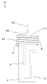
- FIG. 1 is a longitudinal sectional view showing a heater 10 which is an example of the present disclosure.
- the heater 10 includes a rod-like or cylindrical ceramic body 1, a heating resistor 2 embedded at the tip end of the ceramic body 1, and a rear end of the ceramic body 1 embedded in the ceramic body 1.
- the power supply unit 3 is drawn out to the side surface of the side, and the lead terminal 4 fixed to the side surface on the rear end side of the ceramic body 1.
- the front end side of the ceramic body 1 here means one when the ceramic body 1 is divided in half in the longitudinal direction.
- the rear end side of the ceramic body 1 mentioned here means the other when the ceramic body 1 is divided in half in the longitudinal direction.
- the heating resistor 2 is a resistor that generates heat when current flows.
- the heating resistor 2 is embedded in the front end side of the ceramic body 1.
- the heating resistor 2 has, for example, a folded shape.
- the heating resistor 2 has a metal material such as tungsten or tungsten carbide, for example.
- the dimensions of the heat generating resistor 2 can be, for example, 0.1 to 5 mm in width, 0.05 to 0.3 mm in thickness, and 1 to 500 mm in total length.
- the power feeding portion 3 is formed to extend from the portion joined to the heating resistor 2 to the rear end side of the ceramic body 1 and the back of the ceramic body 1. At the end side, there is a portion formed to extend from the inside of the ceramic body 1 to the side surface of the ceramic body 1. Further, in the case where the heat generating resistor 2 has a folded shape, the feed portions 3 may be provided at both ends of the heat generating resistor 2 respectively. In this case, one of the feeding parts 3 may be drawn out to the side surface on the rear end side of the ceramic body 1.
- the feeding portion 3 has a metal material containing, for example, tungsten or tungsten carbide, tungsten nitride, molybdenum, or ceramic powder such as silicon nitride. For example, by making the cross-sectional area larger than the heating resistor 2, the resistance value per unit length may be low. Thereby, the calorific value in the feed section 3 can be reduced.
- the dimensions of the feeding portion 3 can be, for example, 0.1 to 5 mm in width, 0.005 to 0.3 mm in thickness, and 1 to 100 mm in total length.
- the entire device does not spread in the radial direction of the ceramic body 1 and can be miniaturized. As a result, the mountability of the heater 10 can be enhanced.
- a gap is provided between the ceramic body 1 and the second portion 42.
- the second portion 42 can be deformed.
- the second portion 42 can absorb an external force by deformation of the second portion 42. Therefore, it is possible to reduce the possibility that stress is concentrated on the bonding portion between the ceramic body 1 and the lead terminal 4.
- the possibility of breakage of the joint between the ceramic body 1 and the lead terminal 4 can be reduced.
- the durability of the heater 10 can be improved.
- the other end of the second portion 42 is, for example, 0.01 to 1 mm away from the end face of the ceramic body 1.
- the first portion 41 and the second portion 42 may be smoothly continuous.
- “smoothly continuous” means that the side surface of the first portion 41 and the side surface of the second portion 42 are continuous so as to form a curved surface.
- the second portion 42 may be curved. Thereby, when an external force is applied to the second portion 42, the stress generated in the second portion 42 can be dispersed. Therefore, stress is concentrated on a part of the lead terminal 4 and the possibility of breakage of the lead terminal 4 can be reduced. As a result, the durability of the heater 10 can be improved.
- the second portion 42 may have an arc shape which is convex in a direction away from the rear end surface 11 of the ceramic body 1. In this case, when vibration in the axial direction of the ceramic body 1 is applied to the second portion 42, the vibration can be absorbed by deformation of the second portion 42. As a result, the possibility of stress concentration on the joint between the ceramic body 1 and the lead terminal 4 can be reduced. Therefore, the risk of damage to the lead terminal 4 can be reduced. As a result, the durability of the heater 10 can be improved.
- the lead terminal 4 may further include a third portion 43 which is continuous with the second portion 42 and extends in a direction away from the rear end surface 11.
- a third portion 43 which is continuous with the second portion 42 and extends in a direction away from the rear end surface 11.
- the third portion 43 may have a portion extending in a direction perpendicular to the rear end surface 11 of the ceramic body 1.
- the second portion 42 and the third portion 43 may be smoothly continuous.
- the third portion 43 of the lead terminal 4 it is possible to disperse the stress applied to the portion where the second portion 42 and the third portion 43 are continuous. Therefore, the possibility that the part which the 2nd part 42 and the 3rd part 43 continue may be damaged can be reduced. As a result, the durability of the lead terminal 4 can be improved.
- “smoothly continuous” means that the side surface of the second portion 42 and the side surface of the third portion 43 are continuous so as to form a curved surface.
- the second portion 42 may extend in the direction away from the rear end surface 11 and may be bonded to the outer edge portion of the rear end surface 11 by the bonding material 5.
- the bonding strength between the ceramic body 1 and the lead terminal 4 is increased by the bonding material 5, it is possible to provide a gap in which the second portion 42 is deformed when an external force is applied to the second portion 42.
- the durability of the heater 10 can be improved.
- the outer edge portion is an outer side of an imaginary circle having a half diameter and the same center as the rear end surface 11 of the rear end surface 11. It is an area.
- the shape of rear end face 11 of ceramic body 1 is a quadrilateral, it is a similar shape to rear end face 11 of rear end face 11 in a region outside a virtual quadrilateral whose half length is half and whose center is the same. is there.
- the first portion 41 may extend so as to surround the outer peripheral surface of the ceramic body 1 in the circumferential direction of the ceramic body 1.
- the first portion 41 may spirally surround the outer peripheral surface of the ceramic body 1. Therefore, the first portion 41 can be hardly peeled off from the ceramic body 1 against external force from various directions in the circumferential direction.
- the durability of the heater 10 can be improved.
- the first portion 41 may be wound 2 to 6 times on the side surface on the rear end side of the ceramic body 1.
- the bonding material 5 may be provided on the whole of the ceramic body 1 in the circumferential direction, and the ceramic body 1 and the lead terminal 4 may be bonded on the whole of the ceramic body 1 in the circumferential direction.
- the inner curve of the lead terminal 4 when viewed in cross section or side A line connecting the start point of the first portion and the start point of the outer curve can be used as the boundary between the first portion 41 and the second portion 42.
- a line connecting the second portion 42 and the vertex of the outer broken line can be used as the boundary between the second portion 42 and the third portion 43.
- Ceramic body 11 Rear end face 2: Heating resistor 3: Feeding part 4: Lead terminal 41: First part 42: Second part 43: Third part 5: Bonding material 10: Heater
Landscapes
- Engineering & Computer Science (AREA)
- Chemical & Material Sciences (AREA)
- Combustion & Propulsion (AREA)
- Mechanical Engineering (AREA)
- General Engineering & Computer Science (AREA)
- Resistance Heating (AREA)
Abstract
本開示のヒータ10は、セラミック体1と、該セラミック体1の先端側に埋設された発熱抵抗体2と、前記セラミック体1に埋設されて前記セラミック体1の後端側の側面に引き出された給電部3と、該給電部3に電気的に接続されており、前記セラミック体1の後端側の側面に固定されているリード端子4とを有しており、該リード端子4は、前記セラミック体1の後端側の側面に固定されている部分から前記セラミック体1の後端面11より後方まで伸びる第1部分41と、該第1部分41に連続しており、前記後端面11に対して垂直な方向から見たときに前記セラミック体1に重なる第2部分42とを有しており、前記セラミック体1と前記第2部分42との間に、隙間を有している。
Description
本開示は、例えば燃焼式車載暖房装置における点火用もしくは炎検知用のヒータ、石油ファンヒータ等の各種燃焼機器の点火用のヒータ、ディーゼルエンジンのグロープラグ用のヒータ、酸素センサ等の各種センサ用のヒータまたは測定機器の加熱用のヒータ等に利用されるヒータに関するものである。
ヒータとして、例えば、特開2006-258417号公報(以下、特許文献1という)に記載のセラミックヒータが知られている。特許文献1に開示されたセラミックヒータは、棒状のセラミックヒータ本体と、セラミックヒータ本体中の先端側に埋設された抵抗発熱体と、抵抗発熱体に接続された電極取り出し用リードと、セラミックヒータ本体の後端において電極取り出し用リードに接続されたリード端子とを備えている。リード端子は、セラミックヒータ本体の後端面に密着して設けられている。
本開示の一例のヒータは、棒状または筒状のセラミック体と、該セラミック体の先端側に埋設された発熱抵抗体と、該発熱抵抗体に電気的に接続されており、前記セラミック体に埋設されて前記セラミック体の後端側の側面に引き出された給電部と、該給電部に電気的に接続されており、前記セラミック体の後端側の側面に固定されているリード端子とを有しており、該リード端子は、前記セラミック体の後端側の側面に固定されている部分から前記セラミック体の後端面より後方まで伸びる第1部分と、該第1部分に連続しており、前記後端面に対して垂直な方向から見たときに前記セラミック体に重なる第2部分とを有しており、前記セラミック体と前記第2部分との間に、隙間を有している。
本開示のヒータ10の一例について、図面を用いて詳細に説明する。
図1は、本開示の一例であるヒータ10を示す縦断面図である。図1に示すように、ヒータ10は、棒状または筒状のセラミック体1と、セラミック体1の先端側に埋設された発熱抵抗体2と、セラミック体1に埋設されてセラミック体1の後端側の側面に引き出された給電部3と、セラミック体1の後端側の側面に固定されているリード端子4とを備えている。なお、ここでいうセラミック体1の先端側とは、セラミック体1を長手方向で半分に分けたときの一方を意味している。また、ここでいうセラミック体1の後端側とは、セラミック体1を長手方向で半分に分けたときの他方を意味している。
セラミック体1は、発熱抵抗体2を保護するために設けられる部材である。セラミック体1の形状は、棒状または筒状の部材である。棒状としては、例えば、円柱状または角柱状等の柱状が挙げられる。筒状としては、例えば、円筒状または角筒状等が挙げられる。セラミック体1は、絶縁性のセラミック材料を有する。絶縁性のセラミック材料としては、例えば酸化物セラミックス、窒化物セラミックスまたは炭化物セラミックス等を用いることができる。セラミック体1の寸法は、例えばセラミック体1の形状が円柱状のときは、直径を0.5~100mmに、長さを1~200mmにすることができる。
なお、セラミック体1には、発熱抵抗体2に含まれる金属元素の化合物が含まれていてもよく、例えば発熱抵抗体2にタングステンまたはモリブデンが含まれている場合は、WSi2またはMoSi2が含まれていてもよい。このようにすることで、母材であるセラミックスの熱膨張率を発熱抵抗体2の熱膨張率に近づけることができ、ヒータ10の耐久性を向上させることができる。
発熱抵抗体2は、電流が流れることによって発熱する抵抗体である。発熱抵抗体2は、セラミック体1の先端側に埋設されて設けられている。発熱抵抗体2は、例えば、折り返し形状を有している。発熱抵抗体2は、例えばタングステンまたは炭化タングステン等の金属材料を有する。発熱抵抗体2の寸法は、例えば幅を0.1~5mmに、厚みを0.05~0.3mmに、全長を1~500mmにすることができる。
給電部3は、発熱抵抗体2に電気を供給するための部材である。給電部3は、セラミック体1に埋設されて設けられている。また、給電部3は、セラミック体1の内部からセラミック体1の後端側の側面に引き出されている。給電部3は、セラミック体1の内部において発熱抵抗体2に電気的に接続されている。本開示のヒータ10の一例においては、給電部3の一端が発熱抵抗体2に接続されており、給電部3の他端が後端側の側面においてリード端子4に接合されている。
また、本開示のヒータ10の一例において、給電部3は、発熱抵抗体2に接合されている部分からセラミック体1の後端側まで伸びるように形成されている部分と、セラミック体1の後端側においてセラミック体1の内部からセラミック体1の側面まで伸びるように形成される部分とを有している。また、発熱抵抗体2が折り返し形状を有している場合においては、給電部3は、発熱抵抗体2の両端にそれぞれ設けられていてもよい。この場合は、一方の給電部3が、セラミック体1の後端側の側面に引き出されていればよい。
給電部3は、例えばタングステンまたは炭化タングステン、窒化タングステン、モリブデン、あるいはこれらに窒化珪素等のセラミック粉末を含有した金属材料を有する。給電部3は、例えば断面積を発熱抵抗体2よりも大きくすることによって、単位長さ辺りの抵抗値が低くなっていてもよい。これにより、給電部3における発熱量を低減することができる。給電部3の寸法は、例えば幅を0.1~5mmに、厚みを0.005~0.3mmに、全長を1~100mmにすることができる。
リード端子4は、給電部3に電気を供給するための部材である。リード端子4は、外部電源に電気的に接続されている。これにより、給電部3に電気を供給することができる。リード端子4は、セラミック体1の後端側の側面に固定されている。本開示の一例のヒータ10において、リード端子4は、セラミック体1の後端側の側面で給電部3に接合されている。また、本開示の一例のヒータ10において、リード端子4は、給電部3に接合されている部分において、接合材5によってセラミック体1に固定されている。リード端子4は、例えば線状に形成されている。リード端子4は、例えば、ニッケル、鉄またはニッケル系耐熱合金等の金属材料を有する。リード端子4の寸法は、例えば直径0.5~2.0mmに、全長を5~50mmにすることができる。
接合材5は、セラミック体1とリード端子4とを接合するための部材である。接合材5は、セラミック体1の表面に設けられている。接合材5は、リード端子4と給電部3とが接合されている部分にのみ設けられていてもよいし、セラミック体1の側面に広がるように設けられていてもよい。接合材5が、セラミック体1の側面に広がるように設けられていることにより、セラミック体1の側面において、セラミック体1とリード端子4とが接合される領域を広げることができる。そのため、セラミック体1とリード端子4との接合強度を高めることができる。その結果、ヒータ10の長期信頼性を向上させることができる。接合材5としては、例えば半田または銀ろう等のろう材を用いることができる。セラミック体1の側面には、メタライズが設けられており、メタライズの表面に接合材5が設けられていてもよい。また、メタライズは、セラミック体1の後端面11の全体に設けられていてもよい。
リード端子4は、図1に示すように、セラミック体1の後端側の側面に固定されている部分からセラミック体1の後端面11より後方まで伸びる第1部分41を有している。ここでいう後端面11とは、セラミック体1の後端側の端面を意味している。また、ここでいう「後端面11より後方」とは、図1に一点鎖線で示す、セラミック体1の後端面11を含む仮想面上、または、当該仮想面から見て、セラミック体1から離れる方向を意味している。図1に示すように、第1部分41は、セラミック体1の後端面11より後方まで、まっすぐ伸びていてもよい。このときに、第1部分41の寸法は、例えば長さを0.1~10mmにすることができる。
また、図2に示すように、リード端子4は、第1部分41に連続しており、後端面11に対して垂直な方向から見たときにセラミック体1に重なる第2部分42を有している。第2部分42は、一端と他端とを有しており、一端が第1部分41に連続している。このときに、第2部分42の寸法は、例えば長さを0.2~10mmにすることができる。
また、第2部分42は、後端面11に対して垂直な方向から見たときにセラミック体1の外側からセラミック体1の中心に向かって伸びていてもよい。これにより、第2部分42が第2部分42の他端側に向かって引っ張られたときに、リード端子がセラミック体を押す方向に力が加わる。そのため、セラミック体から剥がれる方向に加わる力を低減できる。その結果、リード端子がセラミック体から剥がれるおそれを低減できる。また、第2部分42を後端面11に対して垂直な方向から見たときに、第2部分42の他端が、セラミック体1の中心に位置しているとよい。これにより、第2部分42の他端とヒータ10後方に位置する外部電源とを電気的に接続する場合において、装置全体がセラミック体1の径方向に広がらず、小型化することができる。その結果、ヒータ10の実装性を高めることができる。
本開示の一例のヒータ10においては、図1に示すように、セラミック体1と第2部分42との間に、隙間を有している。これにより、第2部分42に外力が加わったときに、第2部分42が変形することができる。このときに、第2部分42が変形することによって、第2部分42が外力を吸収することができる。そのため、セラミック体1とリード端子4との接合部に応力が集中するおそれを低減することができる。これにより、セラミック体1とリード端子4との接合部が破損するおそれを低減することができる。その結果、ヒータ10の耐久性を向上させることができる。このときに、第2部分42の他端は、例えばセラミック体1の端面から0.01~1mm離れている。
また、図3に示すように、第1部分41と第2部分42とが、滑らかに連続していてもよい。これにより、リード端子4のうち第2部分42に外力が加わったときに、第1部分41と第2部分42とが連続する部分に生じる応力を分散させることができる。そのため、第1部分41と第2部分42とが連続する部分が破損するおそれを低減することができる。その結果、リード端子4の耐久性を向上させることができる。なお、ここでいう「滑らかに連続」とは、第1部分41の側面と第2部分42の側面とが曲面を形成するように連続している状態を意味している。
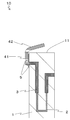
また、図4に示すように、第2部分42が湾曲していてもよい。これにより、第2部分42に外力が加わったときに、第2部分42に生じる応力を分散させることができる。そのため、リード端子4のうち一部分に応力が集中し、リード端子4が破損するおそれを低減することができる。その結果、ヒータ10の耐久性を向上させることができる。また、図4に示すように、第2部分42が、セラミック体1の後端面11から離れる方向に凸な弧状であってもよい。この場合においては、第2部分42に対してセラミック体1の軸方向の振動が加わったときに、第2部分42が変形することによって振動を吸収することができる。これにより、セラミック体1とリード端子4との接合部に応力が集中するおそれを低減することができる。そのため、リード端子4が破損するおそれを低減することができる。その結果、ヒータ10の耐久性を向上させることができる。
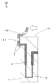
また、図5に示すように、第2部分42が、セラミック体1の後端面11に向かう方向に凸な弧状であってもよい。この場合においては、例えば図5中の白抜き矢印で示すように、第2部分42に対して第2部分42の一端側に向かう方向に外力が加わったときに、第2部分42が変形することによって外力を吸収することができる。これにより、セラミック体1とリード端子4との接合部に応力が集中するおそれを低減することができる。そのため、リード端子4がセラミック体1から剥がれにくくすることができる。その結果、ヒータ10の耐久性を向上させることができる。
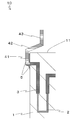
また、図6に示すように、リード端子4が、第2部分42に連続しており、後端面11から離れる方向に伸びる第3部分43をさらに有していてもよい。これにより、第3部分43が外力を受けてセラミック体1の方向に押されたときに、第2部分42と第3部分43とが連続している部分および第1部分41と第2部分42とが連続している部分の2箇所において、リード端子4が変形することができる。その結果、リード端子4が外力を吸収することができる。そのため、セラミック体1とリード端子4との接合部に応力が集中するおそれを低減することができる。これにより、セラミック体1とリード端子4との接合部が破損するおそれを低減することができる。その結果、ヒータ10の耐久性を向上させることができる。このときに、第3部分43の寸法は、例えば長さを1~100mmにすることができる。
また、第3部分43が、セラミック体1の後端面11に対して垂直な方向に伸びる部分を有していてもよい。これにより、セラミック体1の後端面11に対して垂直な方向に伸びる部分を有していない場合と比較して、セラミック体1の後方に位置する部材に電気的に接続するために必要なリード端子4の長さを短くすることができる。その結果、ヒータ10の製造のコストを削減することができる。
また、図7に示すように、第2部分42と第3部分43とが、滑らかに連続していてもよい。これにより、リード端子4のうち第3部分43に外力が加わったときに、第2部分42と第3部分43とが連続する部分に加わる応力を分散させることができる。そのため、第2部分42と第3部分43とが連続する部分が破損するおそれを低減することができる。その結果、リード端子4の耐久性を向上させることができる。なお、ここでいう「滑らかに連続」とは、第2部分42の側面と第3部分43の側面とが曲面を形成するように連続している状態を意味している。
また、図8に示すように、第2部分42が、後端面11から離れる方向に伸びており、接合材5によって後端面11の外縁部分に接合されていてもよい。これにより、接合材5によってセラミック体1とリード端子4との接合強度を高めつつ、第2部分42に外力が加わったときに、第2部分42が変形する隙間を設けることができる。その結果、リード端子4とセラミック体1との接合部が破損するおそれをより低減することができる。その結果、ヒータ10の耐久性を向上させることができる。
ここでいう外縁部分とは、例えば、セラミック体1の後端面11の形状が円形状の場合は、後端面11のうち後端面11に対して直径が半分で中心が同一の仮想円の外側の領域である。また、セラミック体1の後端面11の形状が四角形状の場合は、後端面11のうち後端面11に対して相似形状で一辺の長さが半分で中心が同一の仮想四角形の外側の領域である。
また、図9に示すように、第1部分41が、セラミック体1の外周面をセラミック体1の周方向に囲みながら伸びていてもよい。言い換えると、第1部分41が螺旋状にセラミック体1の外周面を取り囲んでいてもよい。そのため、周方向の様々な方向からの外力に対して、第1部分41がセラミック体1から剥がれにくくすることができる。その結果、ヒータ10の耐久性を向上させることができる。具体的には、第1部分41は、セラミック体1の後端側の側面を2~6回巻かれているとよい。また、セラミック体1の周方向の全体に接合材5が設けられており、セラミック体1の周方向の全体において、セラミック体1とリード端子4とが接合していてもよい。
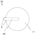
また、図10に示すように、第2部分42が、後端面11に対して垂直な方向から見たときに湾曲していてもよい。これにより、図10の白抜き矢印に示すように、第2部分42に対して第2部分42の一端側に向かう方向に外力が加わった場合において、第2部分42を変形しやすくすることができる。このときに、第2部分42が変形するため、第2部分42が外力を吸収することができる。そのため、セラミック体1とリード端子4との接合部に応力が集中するおそれを低減することができる。これにより、セラミック体1とリード端子4との接合部が破損するおそれを低減することができる。その結果、ヒータ10の耐久性を向上させることができる。
なお、図1、図6、図7および図8に示すように第1部分41から第2部分42にかけてリード端子4が屈曲している場合は、例えば断面視または側面視したときにリード端子4の内側の折れ線の頂点と外側の折れ線の頂点とを結ぶ線を、第1部分41と第2部分42との境界とすることができる。
また図3、図4および図5に示すように第1部分41から第2部分42にかけてリード端子4が湾曲している場合は、例えば断面視または側面視したときにリード端子4の内側の湾曲の始点と外側の湾曲の始点とを結ぶ線を第1部分41と第2部分42との境界とすることができる。
なお、図6および図8に示すように第2部分42から第3部分43にかけてリード端子4が屈曲している場合は、例えば断面視または側面視したときにリード端子4の内側の折れ線の頂点と外側の折れ線の頂点とを結ぶ線を、第2部分42と第3部分43との境界とすることができる。
また図7および図9に示すように第2部分42から第3部分43にかけてリード端子4が湾曲している場合は、例えば断面視または側面視したときにリード端子4の内側の湾曲の終点と外側の湾曲の終点とを結ぶ線を第2部分42と第3部分43との境界とすることができる。
1:セラミック体
11:後端面
2:発熱抵抗体
3:給電部
4:リード端子
41:第1部分
42:第2部分
43:第3部分
5:接合材
10:ヒータ
11:後端面
2:発熱抵抗体
3:給電部
4:リード端子
41:第1部分
42:第2部分
43:第3部分
5:接合材
10:ヒータ
Claims (6)
- 棒状または筒状のセラミック体と、該セラミック体の先端側に埋設された発熱抵抗体と、該発熱抵抗体に電気的に接続されており、前記セラミック体に埋設されて前記セラミック体の後端側の側面に引き出された給電部と、該給電部に電気的に接続されており、前記セラミック体の後端側の側面に固定されているリード端子とを有しており、
該リード端子は、前記セラミック体の後端側の側面に固定されている部分から前記セラミック体の後端面より後方まで伸びる第1部分と、該第1部分に連続しており、前記後端面に対して垂直な方向から見たときに前記セラミック体に重なる第2部分とを有しており、
前記セラミック体と前記第2部分との間に、隙間を有していることを特徴とするヒータ。 - 前記第1部分と前記第2部分とが、滑らかに連続していることを特徴とする請求項1に記載のヒータ。
- 前記第2部分が、湾曲していることを特徴とする請求項1または請求項2に記載のヒータ。
- 前記リード端子が、前記第2部分に連続しており、前記後端面から離れる方向に伸びる第3部分をさらに有することを特徴とする請求項1乃至請求項3のいずれかに記載のヒータ。
- 前記第2部分と前記第3部分とが、滑らかに連続していることを特徴とする請求項4に記載のヒータ。
- 前記第2部分が、前記後端面から離れる方向に伸びており、接合材によって前記後端面の外縁部分に接合されていることを特徴とする請求項1乃至請求項5のいずれかに記載のヒータ。
Priority Applications (1)
| Application Number | Priority Date | Filing Date | Title |
|---|---|---|---|
| JP2019526981A JPWO2019004286A1 (ja) | 2017-06-28 | 2018-06-27 | ヒータ |
Applications Claiming Priority (2)
| Application Number | Priority Date | Filing Date | Title |
|---|---|---|---|
| JP2017-126621 | 2017-06-28 | ||
| JP2017126621 | 2017-06-28 |
Publications (1)
| Publication Number | Publication Date |
|---|---|
| WO2019004286A1 true WO2019004286A1 (ja) | 2019-01-03 |
Family
ID=64741672
Family Applications (1)
| Application Number | Title | Priority Date | Filing Date |
|---|---|---|---|
| PCT/JP2018/024376 Ceased WO2019004286A1 (ja) | 2017-06-28 | 2018-06-27 | ヒータ |
Country Status (2)
| Country | Link |
|---|---|
| JP (1) | JPWO2019004286A1 (ja) |
| WO (1) | WO2019004286A1 (ja) |
Cited By (1)
| Publication number | Priority date | Publication date | Assignee | Title |
|---|---|---|---|---|
| JP2022087682A (ja) * | 2020-12-01 | 2022-06-13 | 京セラ株式会社 | ヒータ |
Citations (4)
| Publication number | Priority date | Publication date | Assignee | Title |
|---|---|---|---|---|
| JP2001267044A (ja) * | 2000-03-23 | 2001-09-28 | Ngk Spark Plug Co Ltd | セラミックヒータ及びその製造方法 |
| JP2006049279A (ja) * | 2004-06-29 | 2006-02-16 | Ngk Spark Plug Co Ltd | セラミックヒータ、グロープラグ及びセラミックヒータの製造方法 |
| JP2009224317A (ja) * | 2008-02-20 | 2009-10-01 | Ngk Spark Plug Co Ltd | セラミックヒータ及びグロープラグ |
| JP2016525202A (ja) * | 2013-06-26 | 2016-08-22 | ローベルト ボッシュ ゲゼルシャフト ミット ベシュレンクテル ハフツング | グロープラグ |
-
2018
- 2018-06-27 WO PCT/JP2018/024376 patent/WO2019004286A1/ja not_active Ceased
- 2018-06-27 JP JP2019526981A patent/JPWO2019004286A1/ja active Pending
Patent Citations (4)
| Publication number | Priority date | Publication date | Assignee | Title |
|---|---|---|---|---|
| JP2001267044A (ja) * | 2000-03-23 | 2001-09-28 | Ngk Spark Plug Co Ltd | セラミックヒータ及びその製造方法 |
| JP2006049279A (ja) * | 2004-06-29 | 2006-02-16 | Ngk Spark Plug Co Ltd | セラミックヒータ、グロープラグ及びセラミックヒータの製造方法 |
| JP2009224317A (ja) * | 2008-02-20 | 2009-10-01 | Ngk Spark Plug Co Ltd | セラミックヒータ及びグロープラグ |
| JP2016525202A (ja) * | 2013-06-26 | 2016-08-22 | ローベルト ボッシュ ゲゼルシャフト ミット ベシュレンクテル ハフツング | グロープラグ |
Cited By (2)
| Publication number | Priority date | Publication date | Assignee | Title |
|---|---|---|---|---|
| JP2022087682A (ja) * | 2020-12-01 | 2022-06-13 | 京セラ株式会社 | ヒータ |
| JP7433200B2 (ja) | 2020-12-01 | 2024-02-19 | 京セラ株式会社 | ヒータ |
Also Published As
| Publication number | Publication date |
|---|---|
| JPWO2019004286A1 (ja) | 2019-12-12 |
Similar Documents
| Publication | Publication Date | Title |
|---|---|---|
| JP5327270B2 (ja) | セラミックヒータ | |
| WO2019004286A1 (ja) | ヒータ | |
| JP2018120794A (ja) | ヒータ | |
| JP6075810B2 (ja) | ヒータおよびグロープラグ | |
| JP6668690B2 (ja) | セラミックグロープラグ | |
| JP6592103B2 (ja) | ヒータおよびこれを備えたグロープラグ | |
| JP6849559B2 (ja) | ヒータ | |
| JP6603321B2 (ja) | ヒータおよびこれを備えたグロープラグ | |
| JP4122675B2 (ja) | セラミックヒータおよびその取付構造 | |
| CN112314051B (zh) | 加热器以及具备该加热器的电热塞 | |
| JP7000241B2 (ja) | ヒータ | |
| JP6725653B2 (ja) | ヒータおよびこれを備えたグロープラグ | |
| JP7116237B2 (ja) | ヒータ | |
| JP2004319459A (ja) | セラミックヒータおよびそれを用いた酸素センサ用ヒータ | |
| JP6923425B2 (ja) | ヒータ | |
| JP6006136B2 (ja) | ガス点火用システム | |
| JP7032954B2 (ja) | ヒータ | |
| JP6665495B2 (ja) | セラミックヒータ | |
| JP6059503B2 (ja) | 圧力センサ付きセラミックグロープラグ | |
| JP6987716B2 (ja) | ヒータ | |
| JPH109572A (ja) | グロープラグ | |
| JP6251578B2 (ja) | グロープラグ | |
| JP2016184515A (ja) | ヒータ | |
| JP2017033637A (ja) | ヒータ及びグロープラグ | |
| WO2020111195A1 (ja) | ヒータおよびこれを備えたグロープラグ |
Legal Events
| Date | Code | Title | Description |
|---|---|---|---|
| 121 | Ep: the epo has been informed by wipo that ep was designated in this application |
Ref document number: 18824803 Country of ref document: EP Kind code of ref document: A1 |
|
| ENP | Entry into the national phase |
Ref document number: 2019526981 Country of ref document: JP Kind code of ref document: A |
|
| NENP | Non-entry into the national phase |
Ref country code: DE |
|
| 122 | Ep: pct application non-entry in european phase |
Ref document number: 18824803 Country of ref document: EP Kind code of ref document: A1 |