WO2018230477A1 - 細胞又は組織の凍結保存用治具 - Google Patents
細胞又は組織の凍結保存用治具 Download PDFInfo
- Publication number
- WO2018230477A1 WO2018230477A1 PCT/JP2018/022105 JP2018022105W WO2018230477A1 WO 2018230477 A1 WO2018230477 A1 WO 2018230477A1 JP 2018022105 W JP2018022105 W JP 2018022105W WO 2018230477 A1 WO2018230477 A1 WO 2018230477A1
- Authority
- WO
- WIPO (PCT)
- Prior art keywords
- cells
- cell
- tissues
- cryopreservation
- tissue
- Prior art date
Links
Images


Classifications
-
- C—CHEMISTRY; METALLURGY
- C12—BIOCHEMISTRY; BEER; SPIRITS; WINE; VINEGAR; MICROBIOLOGY; ENZYMOLOGY; MUTATION OR GENETIC ENGINEERING
- C12M—APPARATUS FOR ENZYMOLOGY OR MICROBIOLOGY; APPARATUS FOR CULTURING MICROORGANISMS FOR PRODUCING BIOMASS, FOR GROWING CELLS OR FOR OBTAINING FERMENTATION OR METABOLIC PRODUCTS, i.e. BIOREACTORS OR FERMENTERS
- C12M21/00—Bioreactors or fermenters specially adapted for specific uses
- C12M21/08—Bioreactors or fermenters specially adapted for specific uses for producing artificial tissue or for ex-vivo cultivation of tissue
-
- A—HUMAN NECESSITIES
- A01—AGRICULTURE; FORESTRY; ANIMAL HUSBANDRY; HUNTING; TRAPPING; FISHING
- A01N—PRESERVATION OF BODIES OF HUMANS OR ANIMALS OR PLANTS OR PARTS THEREOF; BIOCIDES, e.g. AS DISINFECTANTS, AS PESTICIDES OR AS HERBICIDES; PEST REPELLANTS OR ATTRACTANTS; PLANT GROWTH REGULATORS
- A01N1/00—Preservation of bodies of humans or animals, or parts thereof
- A01N1/02—Preservation of living parts
- A01N1/0236—Mechanical aspects
- A01N1/0263—Non-refrigerated containers specially adapted for transporting or storing living parts whilst preserving, e.g. cool boxes, blood bags or "straws" for cryopreservation
- A01N1/0268—Carriers for immersion in cryogenic fluid, both for slow-freezing and vitrification, e.g. open or closed "straws" for embryos, oocytes or semen
-
- A—HUMAN NECESSITIES
- A01—AGRICULTURE; FORESTRY; ANIMAL HUSBANDRY; HUNTING; TRAPPING; FISHING
- A01N—PRESERVATION OF BODIES OF HUMANS OR ANIMALS OR PLANTS OR PARTS THEREOF; BIOCIDES, e.g. AS DISINFECTANTS, AS PESTICIDES OR AS HERBICIDES; PEST REPELLANTS OR ATTRACTANTS; PLANT GROWTH REGULATORS
- A01N1/00—Preservation of bodies of humans or animals, or parts thereof
- A01N1/02—Preservation of living parts
- A01N1/0205—Chemical aspects
- A01N1/021—Preservation or perfusion media, liquids, solids or gases used in the preservation of cells, tissue, organs or bodily fluids
- A01N1/0221—Freeze-process protecting agents, i.e. substances protecting cells from effects of the physical process, e.g. cryoprotectants, osmolarity regulators like oncotic agents
-
- A—HUMAN NECESSITIES
- A01—AGRICULTURE; FORESTRY; ANIMAL HUSBANDRY; HUNTING; TRAPPING; FISHING
- A01N—PRESERVATION OF BODIES OF HUMANS OR ANIMALS OR PLANTS OR PARTS THEREOF; BIOCIDES, e.g. AS DISINFECTANTS, AS PESTICIDES OR AS HERBICIDES; PEST REPELLANTS OR ATTRACTANTS; PLANT GROWTH REGULATORS
- A01N1/00—Preservation of bodies of humans or animals, or parts thereof
- A01N1/02—Preservation of living parts
- A01N1/0236—Mechanical aspects
- A01N1/0242—Apparatuses, i.e. devices used in the process of preservation of living parts, such as pumps, refrigeration devices or any other devices featuring moving parts and/or temperature controlling components
-
- C—CHEMISTRY; METALLURGY
- C12—BIOCHEMISTRY; BEER; SPIRITS; WINE; VINEGAR; MICROBIOLOGY; ENZYMOLOGY; MUTATION OR GENETIC ENGINEERING
- C12M—APPARATUS FOR ENZYMOLOGY OR MICROBIOLOGY; APPARATUS FOR CULTURING MICROORGANISMS FOR PRODUCING BIOMASS, FOR GROWING CELLS OR FOR OBTAINING FERMENTATION OR METABOLIC PRODUCTS, i.e. BIOREACTORS OR FERMENTERS
- C12M21/00—Bioreactors or fermenters specially adapted for specific uses
- C12M21/06—Bioreactors or fermenters specially adapted for specific uses for in vitro fertilization
-
- C—CHEMISTRY; METALLURGY
- C12—BIOCHEMISTRY; BEER; SPIRITS; WINE; VINEGAR; MICROBIOLOGY; ENZYMOLOGY; MUTATION OR GENETIC ENGINEERING
- C12M—APPARATUS FOR ENZYMOLOGY OR MICROBIOLOGY; APPARATUS FOR CULTURING MICROORGANISMS FOR PRODUCING BIOMASS, FOR GROWING CELLS OR FOR OBTAINING FERMENTATION OR METABOLIC PRODUCTS, i.e. BIOREACTORS OR FERMENTERS
- C12M23/00—Constructional details, e.g. recesses, hinges
- C12M23/02—Form or structure of the vessel
- C12M23/12—Well or multiwell plates
-
- C—CHEMISTRY; METALLURGY
- C12—BIOCHEMISTRY; BEER; SPIRITS; WINE; VINEGAR; MICROBIOLOGY; ENZYMOLOGY; MUTATION OR GENETIC ENGINEERING
- C12M—APPARATUS FOR ENZYMOLOGY OR MICROBIOLOGY; APPARATUS FOR CULTURING MICROORGANISMS FOR PRODUCING BIOMASS, FOR GROWING CELLS OR FOR OBTAINING FERMENTATION OR METABOLIC PRODUCTS, i.e. BIOREACTORS OR FERMENTERS
- C12M45/00—Means for pre-treatment of biological substances
- C12M45/22—Means for packing or storing viable microorganisms
Definitions
- the present invention relates to a cell or tissue cryopreservation jig used for cryopreserving cells or tissues.
- Exceptional storage technology for cells or tissues is required in various industrial fields.
- the embryo is cryopreserved, and the embryo is thawed and transferred in accordance with the estrous cycle of the recipient cow.
- human infertility treatment after collecting an egg or ovary from a mother body, it is stored frozen in order to match the timing suitable for transplantation, and thawed at the time of transplantation.
- a slow freezing method As a method for preserving cells or tissues, for example, a slow freezing method is known.
- cells or tissues are first immersed in a preservation solution obtained by adding a freezing-resistant agent to a physiological solution such as phosphate buffered saline.
- a freezing-resistant agent such as phosphate buffered saline.
- compounds such as glycerol and ethylene glycol are used.
- the cells or tissues are cooled to -30 to -35 ° C. at a relatively slow cooling rate (for example, 0.3 to 0.5 ° C./min), thereby allowing intracellular or extracellular or tissue
- a relatively slow cooling rate for example, 0.3 to 0.5 ° C./min
- the vitrified cell or tissue can be stored semipermanently by storing it in liquid nitrogen.
- a vitrification freezing method has been proposed as a method for solving the problems in the slow freezing method.
- the vitrification freezing method is based on the principle that ice crystals are difficult to form even when the temperature is below freezing point by lowering the freezing point of a preservation solution containing a large amount of antifreezing agents such as glycerol, ethylene glycol, DMSO (dimethyl sulfoxide). .
- a preservation solution containing a large amount of antifreeze is called a vitrification solution.
- vitrification freezing method As a specific operation of the vitrification freezing method described above, cells or tissues are immersed in a storage solution containing a large amount of a freezing agent, and then cooled at a temperature of liquid nitrogen ( ⁇ 196 ° C.). Since the vitrification freezing method is such a simple and rapid process, it does not require a long time for the operation for cryopreservation and does not require an apparatus or jig for temperature control. There is.
- the vitrification freezing method in principle, ice crystals do not form inside or outside the cell or tissue, so avoid physical damage (freezing damage) to the cell or tissue during freezing and thawing.
- the concentration of the antifreeze contained in the preservation solution used for vitrification must be high.
- a high concentration of antifreeze contained in a preservation solution has high chemical toxicity to cells or tissues.
- the time during which the cells or tissues are exposed to the preservation solution (that is, the time until they are frozen) is short. Further, from the viewpoint of increasing the freezing rate, it is preferable that the preservation solution present around the cells or tissues is small when the cells or tissues are cryopreserved. It can be said that the smaller the preservation solution present around the cells or tissues, the smaller the heat capacity of the object to be frozen, and the faster the freezing rate of the cells or tissues, which is preferable for vitrification freezing.
- the preservation solution present around the cells or tissues is small is that the preservation solution is quickly diluted into the thawing solution even when thawing after freezing, thereby suppressing re-ice crystal formation in the cells or tissues. Is preferable.
- the amount of the preservative solution present around the cells or tissues is small from the viewpoint of reducing the toxicity derived from the antifreezing agent because the concentration of the antifreezing agent mixed in the melting solution at the time of thawing can be reduced.
- Patent Document 1 shows that application of a vitrification freezing method to animal or human germ cells or somatic cells is extremely useful in terms of cryopreservation and survival rate after thawing.
- the vitrification freezing method is a technique that has been developed mainly using human germ cells, but recently, its application to iPS cells and ES cells has been widely studied.
- Non-Patent Document 1 shows that the vitrification freezing method was effective in preserving Drosophila embryos.
- Patent Document 2 shows that the vitrification freezing method is effective in preservation of plant cultured cells and tissues.
- the vitrification freezing method is known to be useful for the preservation of a wide variety of cells and tissues.
- the so-called cryotop method used in the field of human infertility treatment is a method for cryopreserving eggs using a strip-like flexible, colorless and transparent film as a strip for holding eggs attached.
- a method for cryopreserving eggs using a strip-like flexible, colorless and transparent film as a strip for holding eggs attached There has been proposed a method in which an egg or embryo is placed on the film together with a very small amount of preservation solution under microscope observation and cryopreserved using a tool.
- Patent Document 5 and Patent Document 6 describe a cryopreservation jig having a cell storage recess provided in the longitudinal direction of an elongated living cell adhesion holding section.
- Patent Document 7 an ovum or an embryo is placed on a preservative removal material together with a preservative containing a large amount of antifreeze, and the extra preservative attached to the periphery of the ovum or embryo is removed by aspiration from the bottom.
- a method of cryopreserving has been proposed.
- a preservation save liquid removal material, what has the through-hole by the film-form thing which consists of natural products and synthetic resins, such as a metal net and paper, is described.
- a cryopreservation jig capable of removing excess storage solution and improving workability when placing cells, for example, a storage solution absorber having a specific haze value is described in Patent Document 8.
- Patent Document 9 disclose a vitrification cryopreservation jig having a porous sintered body or a porous structure formed of a material having a specific refractive index as a storage liquid absorber. Is described.
- Patent Document 11 discloses a cryopreservation jig for cells or tissues having a layer containing a water-soluble polymer compound on the outermost surface of a placement part for placing cells or tissues.
- Patent Document 12 describes a cell container having an inner surface on which fine protrusions are formed for the purpose of preventing cells from adhering to the inner surface of the container.
- Patent Document 3 and Patent Document 4 propose a method of obtaining an excellent survival rate by cryopreserving an egg or embryo together with a small amount of a preservation solution by limiting the width of a film on which the egg or embryo is placed. Yes.
- the egg or embryo on the film often sticks to the film surface depending on the state of the object to be frozen, etc., and there is a problem that a high skill is required when collecting these. there were.
- the more the operator cryopreserves the ovum or embryo with a smaller amount of preservation solution there is a problem that the ovum or embryo adheres firmly to the film surface when thawing after freezing.
- Patent Document 5 and Patent Document 6 a method for improving cell dropout during freezing operation by providing a concave portion in which cells are stored in a cell attachment holding portion has been proposed.
- Patent Document 4 there is a problem that a high skill is required when collecting.
- Patent Document 7 proposes a method of cryopreserving these germ cells by removing the extra preservation solution adhering to the periphery of the ovum or embryo from the lower part of the preservation solution removing material.
- Patent Documents 8 to 10 unlike the above-mentioned Patent Document 7 and the like, it is not necessary for the operator to remove excess storage solution adhering to the periphery of the ovum or embryo.
- the body absorbs the preservation solution, the ovum or embryo adheres particularly firmly to the preservation solution absorber, so that there is a problem that a particularly high skill is required when collecting the ovum or embryo.
- Patent Document 11 when a cell or tissue is thawed after freezing, the water-soluble polymer is placed on the placement portion in order to avoid the cells or tissue from sticking to the placement portion of the cryopreservation jig.
- a method for forming a layer containing a compound has been proposed, improvement in the recoverability of cells or tissues during freeze-thawing is a permanent problem, and further improvement has been desired.
- Patent Document 12 in a cell container in which cells are filled with a preservation solution, such as a so-called cell storage vial, the adhesion of cells to the inner surface of the cell container is suppressed by forming a fine protrusion shape on the inner surface of the cell container.
- a method has been proposed.
- the above technique suppresses adhesion, and is not a technique for positively detaching and using attached cells for the purpose of preservation.
- cryotop method in which a very small number (in many cases, about 1 to 3) of cells or tissues are placed together with a very small amount of preservation solution, the cells can be recovered smoothly without being firmly fixed during thawing.
- the main object of the present invention is to provide a cell or tissue cryopreservation jig capable of easily and reliably performing cryopreservation of cells or tissues. More specifically, when a cell or tissue is immersed in a preservation solution and placed on a placement portion of a cryopreservation jig and cryopreserved, the cell or tissue is securely held on the placement portion surface.
- an object of the present invention is to provide a cryopreservation jig that can reduce the amount of extra storage solution on the outer periphery of the placed cell or tissue, and that can quickly recover the cell or tissue during freezing and thawing. .
- a cryopreservation jig having a placement part for placing a cell or tissue together with a preservation solution, wherein the placement part surface has a convex part for retaining the cell or tissue, and a concave part for storing the preservation liquid.
- a jig for cryopreservation of a cell or tissue characterized by comprising: (2) The cell according to (1) above, wherein the height of the convex part holding the cell or tissue is 1/100 or more and less than 1/2 of the average diameter of the cell or tissue Jig for cryopreservation of tissue.
- the cryopreservation jig that can be reliably held on the surface of the part and that can quickly recover cells or tissues in a melting operation.
- Use of the cryopreservation jig of the present invention makes it possible to easily and reliably perform cryopreservation of cells or tissues.
- FIG. 1 is an overall view showing an example of a jig for cryopreservation of cells or tissues of the present invention. It is a general view which shows another example of the jig for cryopreservation of the cell or tissue of this invention. It is a general view which shows another example of the jig for cryopreservation of the cell or tissue of this invention. It is a sectional structure schematic diagram showing an example of a mounting part in a jig for cryopreservation of a cell or tissue of the present invention. It is a sectional structure schematic diagram showing another example of the mounting part in the jig for cryopreservation of the cell or tissue of the present invention. FIG.
- FIG. 5 is a model diagram when cells and a preservative solution are dropped and attached on the mounting portion shown in FIG. 4. It is a perspective view which shows an example of the mounting part in the jig
- FIG. 13 is a model diagram when cells and a storage solution are dropped and attached in the mounting portion shown in FIG. 12. It is a figure which shows an example of the metal mold
- the jig for cryopreservation of the present invention is used when cryopreserving cells or tissues.
- the cell includes not only a single cell but also a cell population of an organism composed of a plurality of cells.
- the cell population composed of a plurality of cells may be a cell population composed of a single type of cell or a cell population composed of a plurality of types of cells.
- the tissue may be a tissue composed of a single type of cell or a tissue composed of a plurality of types of cells, and includes non-cellular substances such as an extracellular matrix in addition to cells. Things can be used.
- the cryopreservation work in this specification includes freezing work in which cells or tissues are frozen using a cryogenic refrigerant, storage work for storing cells or tissues in a cryogenic refrigerant, and thawing the cells or tissues in a thawing solution. It shall include a series of melting operations.
- the cryopreservation jig of the present invention is used for cryopreservation work, and is preferably used for vitrification cryopreservation work. Specifically, the cryopreservation jig of the present invention is for immersing and freezing a cryopreservation jig having a placement portion on which cells or tissues are placed in a cooling solvent such as liquid nitrogen. In addition, when thawing the cells or tissues placed on the placement section, the cells or tissues are taken out of the cooling medium together with the cryopreservation jig and immersed in the melting solution for thawing. is there.
- cryopreservation jig of the present invention When the cryopreservation jig of the present invention is used, cells or tissues can be reliably held on the surface of the placement part during cryopreservation. In addition, since the preservation solution dropped together with the cells or tissues is stored in the lower part of the placed cells or tissues, there is less excess preservation solution around the cells or tissues, and the cells or tissues are stored frozen with a good survival rate. can do. Furthermore, when thawing cells or tissues after cryopreservation, there is a preservation solution stored between the cells or tissues placed on the placement portion and the placement portion surface. Is melted from the vitrified state, fluidity is quickly recovered, and the cells or tissues can be easily detached and collected from the surface of the mounting portion as they are diluted with the melt.
- the cryopreservation jig of the present invention when used, the work for cryopreserving cells or tissues can be easily and reliably performed.
- the cell or tissue cryopreservation jig of the present invention can be restated as a cell or tissue storage device, a cell or tissue cryopreservation device, or a cell or tissue storage device.
- the surface of the placement part on which cells or tissues are placed has a convex part that holds the cells or tissue and a concave part that stores the preservation solution.
- the uneven shape on the placement unit surface suppresses the spread of the preservation solution. For this reason, the position of the placed cell or tissue does not move greatly, and the operation of dropping attachment using a pipette or the like is easy.
- the convex part of the mounting part surface can hold
- the recessed portion formed in the lower part of the placed cell or tissue it is possible to reduce the extra storage solution on the outer periphery of the cell or tissue by storing the preservation solution dropped and attached together with the cell or tissue, Rapid vitrification freezing becomes possible.
- the thawing operation when the cells or tissues are thawed, there is a storage solution (frozen) stored between the cells or tissues and the surface of the mounting portion, so that the cells or tissues are thawed from the vitrified state.
- the cell or tissue can be easily peeled off and collected from the surface of the mounting portion as the preservation solution having recovered fluidity is diluted with the melt.
- tool for cryopreservation of this invention has a preservation
- the convex part holding the cell or tissue which is the surface shape of this invention on the surface and the recessed part which stores a preservation
- the storage solution absorber absorbs excess storage solution, so that no other operation for removing the excess storage solution is required and the workability is greatly improved. To do.
- the cells or tissues thus manipulated are covered with a very small amount of preservation solution, and can be quickly frozen even when freezing.
- the vitrification freezing method described above chemical toxicity due to the preservation solution containing a large amount of antifreeze becomes a problem, but according to the cryopreservation jig in which the mounting portion has the preservation solution absorber.
- the viability of the cells or tissues can be expected to be improved because the amount of the preservation solution around the placed cells or tissues becomes extremely small.
- cryopreservation jig The configuration of the cryopreservation jig according to the present invention will be described below.
- the surface of the placement portion on which the cells or tissues are placed has a convex portion that holds the cells or tissue and a concave portion that stores the preservation solution.
- the surface of the placement portion on which the cells or tissues are placed corresponds to the surface portion on which the cells or tissues are actually placed together with the preservation solution.
- the shape of the placement portion on which the cell or tissue is placed is not particularly limited as long as the shape can place the cell or tissue.
- the placing portion has a substantially sheet shape.
- a cryopreservation jig having a substantially sheet-like placement portion is one of the preferred embodiments of the present invention.
- the substantially sheet shape in the present invention means a shape having a flat surface from a macro viewpoint, and examples thereof include a flat sheet shape, a sheet shape having a curvature, a corrugated sheet shape, and a V-shaped sheet shape.
- the convex portion that holds the cell or tissue of the placement portion corresponds to a structural portion that contacts the cell or tissue to be placed.
- this convex part is the structure of the objective which hold
- the concave portion for storing the storage solution in the mounting portion stores the storage solution without contacting the surface of the cell with the storage solution.
- the recess may be at least one or more than one cell to be placed.
- save liquid of each mounting part may be connected.
- the aggregate portion having a plurality of convex portions may be present at one location, or the aggregate portion having a plurality of convex portions may be present at a plurality of locations.
- the pattern pitch between the convex parts is 95% or less of the average diameter of the mounting object.
- the pattern pitch between the convex portions is the distance between the centers of the nearest convex portions when viewed from above.
- the convex portion may or may not exist at a place where cells or tissues are not placed.
- the height of the convex part (that is, the depth of the concave part) holding the cell or tissue of the placement part can be appropriately selected depending on the size of the cell or tissue to be placed, but is 100 nm or more. It is preferable. When the height of the convex portion is less than 100 nm, the amount of the storage solution stored in the concave portion is insufficient, and the effect to be obtained may not be obtained.
- the height of the convex part for holding cells or tissues is preferably 1/100 or more and less than 1/2 of the average diameter of the cells or tissues to be placed. This makes it easier to detach and collect cells or tissues during the thawing operation.
- the convex part formed on the surface of the cell or tissue placement part reduces the contact area between the placement part and the placement object, so that the placement object can be stored in the cryopreservation jig during the melting operation. Although it can promote peeling from a mounting part, such an effect becomes especially remarkable when the height of this convex part is made into 1/100 or more of the average diameter of a cell or a structure
- the average diameter of cells or tissues is an average of equivalent volume sphere diameters.
- the equivalent volume sphere diameter refers to the diameter of a cell or tissue when it is spherical.
- the diameter corresponding to the sphere is obtained from the volume of the cell or tissue, and this value is adopted as the equivalent volume sphere equivalent diameter.
- the above-mentioned equivalent volume sphere diameter of the cell or tissue is the average diameter.
- the cryopreservation jig of the present invention is preferably used as a cryopreservation jig for cells or tissues having an average diameter of 1 to 500 ⁇ m.
- the height of the convex portion is 1 ⁇ 2 or more of the average diameter of the cells or tissues, it may be difficult for the placing object to easily peel from the cryopreservation jig during the melting operation. is there.
- the reason for this is not clear, but in general, cells or tissues are placed on a placement portion together with a small amount of a preservation solution by a culture technician's procedure in order to reduce the chemical toxicity of the antifreeze agent.
- the height of the convex portion is 1 ⁇ 2 or more of the average diameter of the cell or tissue, it is difficult to freeze in a state where an appropriate liquid film is formed between the convex portion and the cell or tissue. And good melt peelability may be difficult to obtain.
- an embodiment of the present invention is a cryopreservation method in which cells or tissues are placed on a cryopreservation jig and cryopreserved.
- the tool has a placement part for placing a cell or tissue, and the surface of the placement part has a convex part for holding the cell or tissue, and a concave part for storing a preservation solution, and the height of the convex part is
- the cryopreservation method is 1/100 or more and less than 1/2 of the average diameter of the obtained cells or tissues.
- the arithmetic average roughness Ra of the surface of the mounting portion described above is 1.0 ⁇ m or more. Accordingly, it is possible to provide a cryopreservation jig that can more easily detach and collect cells or tissues when the cells or tissues are thawed.
- the arithmetic average roughness Ra is a value obtained by extracting a part of the measured roughness curve with a reference length and expressing the uneven state in the section as an average value.
- the arithmetic average roughness Ra can be measured using a stylus type surface roughness meter, and the cutoff value at that time is 0.8 mm, and the reference length is 4.0 mm.
- the upper limit value of the arithmetic average roughness Ra is preferably 10 ⁇ m or less.
- the arithmetic average roughness Ra of the surface of the mounting portion is more preferably 1.0 to 5 ⁇ m, and further preferably 1.5 to 3.5 ⁇ m.
- the effects of the present invention described above can be more fully exhibited.
- the convex part for holding cells or tissues and the concave part for storing the preservation solution of the jig for cryopreservation of the present invention may have a regular and uniform pattern, or a regular and non-uniform pattern, that is, a random pattern. It may be.
- the surface shape pattern consisting of convex portions for holding cells or tissues of the cryopreservation jig of the present invention and concave portions for storing the preservation solution may be a pillar shape, a block shape, a stripe shape, a hole shape, a weight shape, or the like. The pattern can be used.
- the mounting portion included in the cryopreservation jig of the present invention may be made of a non-absorber that does not absorb the storage solution, or may have a storage solution absorber that absorbs the storage solution.
- a polyester resin such as polyethylene terephthalate (PET) or polyethylene naphthalate (PEN), or an acrylic resin , Epoxy resin, silicone resin, polycarbonate resin, diacetate resin, triacetate resin, polyarylate resin, polyvinyl chloride, polysulfone resin, polyethersulfone resin, polyimide resin, polyamide resin, polyolefin resin, cyclic polyolefin resin, polytetrafluoro
- Various resins made of fluorine resin such as ethylene (PTFE), various metals such as aluminum, aluminum alloy, gold, gold alloy, silver, silver alloy, iron, copper, copper alloy, stainless steel, glass, rubber, etc. may be used. it can.
- a convex part for holding cells or tissues and a concave part for storing a preservation solution can be formed on the surface of the mounting part of the cryopreservation jig of the present invention by various methods depending on the material. Specifically, when a resin such as PET is used as the material for the mounting portion, desired convex portions and concave portions are formed on the surface of the mounting portion by methods such as cutting, surface polishing, and pressure transfer of the mold. Is possible. When metal is used as the material for the placement portion, it is possible to form desired convex portions and concave portions on the placement portion surface by methods such as cutting, surface polishing, and shot peening. When glass is used as a material for the placement portion, desired projections and recesses can be formed on the placement portion surface by a method such as etching or fine polishing.
- the cell or tissue placement part of the jig for cryopreservation of the present invention has a preservation solution absorber
- excess preservation solution can be removed from the surroundings of the cell or tissue, It is preferable from the viewpoint of reducing toxicity.
- the cell or tissue placement part has a preservation solution absorber
- a step for removing excess vitrification solution required particularly in the vitrification cryopreservation method is not required, and preservation around the cell or tissue is performed.
- the amount of the liquid is extremely small, an improvement in the survival rate of cells or tissues can be expected.
- the cell or tissue placement part of the jig for cryopreservation of the present invention has a preservation solution absorber
- a preservation solution absorber a porous structure made of fibers, a porous structure made of resin, A porous structure made of a metal or a porous structure made of a metal oxide can be used.
- “Porosity” in the present invention means that the above-mentioned absorber is a structure having pores (pores) on the surface, and is a structure having continuous pores on the surface and inside of the absorber. It is more preferable.
- the thickness of the preservation solution absorber (the above-mentioned various porous structures) is preferably 10 ⁇ m to 5 mm, more preferably 20 ⁇ m to 2.5 mm.
- the preservation solution absorber is a thin sheet, the above-described non-absorber can be combined as a support as a reinforcing member.
- the porous structure composed of fibers used as the preservation solution absorber is exemplified by paper or non-woven fabric
- the paper is a paper in which the ratio of the binder component such as a binder to the whole paper is 10% by mass or less. Is preferable, more preferably 5% by mass or less, and further preferably 3% by mass or less. Thereby, excellent absorbability of the preservation solution is obtained.
- the ratio of the papermaking chemicals contained in the paper to the whole paper is preferably 1% by mass or less.
- fluorescent whitening agents, dyes, cationic sizing agents, and the like may have an effect on cells.
- the porous structure made of fibers is paper, it is preferably paper having a density of 0.1 to 0.6 g / cm 3 and a basis weight of 10 to 130 g / m 2 .
- a paper having a density of 0.12 to 0.3 g / cm 3 and a basis weight of 10 to 100 g / m 2 has excellent absorbability of the storage solution. It is preferable because it is possible to provide a cryopreservation jig having excellent cell or tissue visibility so that the cells or tissues placed thereon can be observed.
- the fibers contained in the nonwoven fabric are cellulose fibers, rayon fibers and cupra fibers that are regenerated fibers made of cellulose fibers, and semisynthetic fibers made from cellulose fibers.
- Acetate fiber, polyester fiber, nylon fiber, acrylic fiber, polypropylene fiber, polyethylene fiber, polyvinyl chloride fiber, vinylidene fiber, polyurethane fiber, vinylon fiber, glass fiber, silk fiber, etc. Can be used.
- cellulose fiber, cellulose fiber-derived rayon fiber and cupra fiber that are cellulose regenerated fibers, and acetate fiber that is semi-synthetic fiber from cellulose fibers are preferable.
- the porous structure made of fibers is a nonwoven fabric
- it is preferably a nonwoven fabric having a density of 0.1 to 0.4 g / cm 3 and a basis weight of 10 to 130 g / m 2 .
- a non-woven fabric having a density of 0.12 to 0.3 g / cm 3 and a basis weight of 10 to 100 g / m 2 is excellent in storage solution absorbability and freezing with excellent cell or tissue visibility. This is preferable because a storage jig can be provided.
- the non-woven fabric used as the preservative liquid absorber is preferably 10% by mass or less, more preferably 5% by mass or less, as in the case of the paper described above, the proportion of the binder component such as the binder in the non-woven fabric. Furthermore, the nonwoven fabric which is 3 mass% or less is preferable. In particular, a non-woven fabric containing no binder is preferable.
- Non-woven fabrics have a variety of production methods, unlike paper.
- non-woven fabrics with reduced binder components as described above are produced by spunbonding and melt-blowing methods, and fibers are arranged by wet or dry methods.
- the nonwoven fabric manufactured by the hydroentanglement method or the needle punch method can be used suitably.
- preferred fibers contained in the nonwoven fabric in the present invention include cellulose fibers, fibers derived from cellulose fibers, rayon fibers and cupra fibers that are cellulose regenerated fibers, and acetate fibers that are semi-synthetic fibers from cellulose fibers.
- a hydroentanglement method or a needle punch method is suitable regardless of a wet method or a dry method.
- porous structure made of a resin used as a storage liquid absorber in the present invention examples include those described in Japanese Patent Publication No. 42-13560 and Japanese Patent Application Laid-Open No. 08-283447, which are stretched at least in the uniaxial direction.
- Examples include a porous structure in which a porous structure is formed by filling a solid powder of thermoplastic resin in a mold, heating and sintering, fusing the surface of the powder particles, and cooling.
- a porous structure is used as a preservation solution absorber, it is possible to provide a cryopreservation jig having excellent preservation solution absorbability and cell or tissue visibility, which is preferable.
- Examples of the resin that forms the porous structure (porous resin sheet) made of the above-described resin include various polyethylenes such as low density polyethylene, high density polyethylene, and ultrahigh molecular weight polyethylene, polypropylene, polymethyl methacrylate, polystyrene, and polytetrafluoro.
- Fluorine resins such as ethylene and polyvinyl difluoride, ethylene-vinyl acetate copolymer, polyamide, styrene-acrylonitrile copolymer, styrene-butadiene-acrylonitrile terpolymer, polycarbonate, polyvinyl chloride, and the like.
- a porous resin sheet using a fluororesin such as polytetrafluoroethylene or polyvinylidene difluoride is a cell or tissue under observation with a transmission microscope when the cell or tissue is placed on a placement portion together with a preservation solution. Is significantly improved, and it is possible to provide a cryopreservation jig that is particularly excellent in the visibility of cells or tissues.
- a membrane filter for filtration which is commercially available for physics and chemistry experiment use or research use, can also be used as the porous resin sheet.
- the porous structure made of a metal used as a preservation solution absorber includes copper, copper alloy, aluminum, aluminum alloy, gold, gold alloy, silver, silver alloy, tin, zinc, lead, titanium, nickel,
- the porous metal sheet which consists of metals, such as stainless steel, is mentioned.
- the porous structure which consists of metal oxides such as a silica, an alumina, a zirconium, quartz glass, can be utilized preferably.
- the porous structure made of metal and the porous structure made of metal oxide may be a porous structure containing two or more kinds of the above-described metal and metal oxide.
- a porous structure made of a metal oxide is preferable because it can provide a cryopreservation jig having excellent cell or tissue visibility under observation with a transmission microscope.
- a generally known method can be used as a method for producing a porous structure made of a metal or a porous structure made of a metal oxide used as a preservation solution absorber.
- a method such as a powder metallurgy method or a spacer method can be used.
- a so-called powder space holder method in which resin injection molding and powder metallurgy are combined can be preferably used.
- a method described in International Publication No. 2006/041118 or Japanese Patent No. 4577862 can be used.
- the metal powder is baked and solidified, and the resin serving as the spacer is vaporized to be porous.
- a metal sheet can be obtained.
- a resin binder can be mixed in addition to the metal powder and the resin serving as the spacer.
- the manufacturing method of metal porous bodies such as the foaming melting method and gas expansion method which inject
- the manufacturing method like the slurry foaming method which manufactures a metal porous body using a foaming agent can also be used.
- the preservation solution absorber is a porous structure made of a metal oxide, for example, methods described in JP2009-29692A and JP2002-160930A can be used.
- the preservation solution absorber is a porous structure made of the above-mentioned resin, a porous structure made of a metal, and a porous structure made of a metal oxide
- the pore diameter of the porous body Is preferably 0.02 to 50 ⁇ m, more preferably 0.05 to 25 ⁇ m.
- the storage solution may not have sufficient absorption performance when the storage solution is dropped.
- the pore diameter of the porous body is the diameter of the largest pore measured by a bubble point test.
- the average pore diameter is measured from image observation of the surface and cross section of the porous body.
- the porosity of the preservation solution absorber is preferably 20% by volume or more, more preferably 30% by volume or more.
- the preservation solution absorber is a porous body such as a porous structure made of the above-described resin, a porous structure made of a metal, and a porous structure made of a metal oxide
- the inside of the porous body The pores preferably have a continuous structure not only in the thickness direction but also in a direction perpendicular to the thickness direction. With such a structure, since the pores inside the porous body can be used effectively, high absorption performance of the preservation solution can be obtained.
- the thickness of the preservation solution absorber and the porosity of the porous body can be appropriately selected according to the type of cells or tissues used, the amount of the preservation solution dripped together with the cells or tissues, and the like.
- the above porosity is defined by the following formula.
- the placement part for placing the cell or tissue of the cryopreservation jig of the present invention has a preservation solution absorber, as described above, the convexity for holding the cell or tissue by various methods depending on the material. And a recess for storing the storage solution.
- a porous structure made of fibers or a porous structure made of a resin such as polytetrafluoroethylene is used as the storage liquid absorber, a method such as pressure transfer of a mold is used. It is possible to form desired convex portions and concave portions on the surface of the storage liquid absorber used for the mounting portion.
- the preservation liquid absorber When a porous structure made of a metal is used as the preservation liquid absorber, desired projections and depressions are formed on the surface of the preservation liquid absorber by methods such as etching, shot peening, and surface polishing. Is possible.
- save liquid absorber has a pore, it is preferable to form a desired convex part and a recessed part in the preservation
- the mounting portion having the storage liquid absorber has a convex portion and a concave portion on the surface of the storage liquid absorber as a convex portion and a concave portion on the surface of the mounting portion.
- the height of the convex part formed on the mounting part by the method described above can be obtained by measuring the shape with a confocal microscope.
- Other methods for obtaining the height of the convex portion formed on the mounting portion include, for example, a method of analyzing using the depth synthesis function of the digital microscope VHX-5000 manufactured by Keyence Corporation, and a method manufactured by Keyence Corporation. Examples include a method of analyzing with a shape analysis laser microscope VK-X1000, a method of observing a cross section of the mounting portion with an electron microscope, and the like.
- the pattern pitch of the convex part mentioned above can also be calculated
- an adhesive layer can be provided between the storage liquid absorber and the non-absorber.
- the adhesive layer can contain an instant adhesive composition typified by a moisture-curable adhesive substance, a hot melt adhesive composition, a photocurable adhesive composition, etc., for example, polyvinyl alcohol, hydroxy Water-soluble polymer compounds such as cellulose, polyvinyl pyrrolidone, starch paste, vinyl acetate resin, acrylic resin, epoxy resin, urethane resin, elastomer resin, cyanoacrylate resin, fluorine resin, silicone resin, Nitrocellulose resin, nitrile rubber resin, styrene-butadiene resin, urea resin, styrene resin, phenol resin, polyimide resin, polyamide resin, polyester resin, bismaleimide resin, olefin resin, EVA A composition containing a water-insoluble resin such as
- the adhesive layer may contain one type of resin or may contain a plurality of types of resins.
- the solid content of the adhesive layer is preferably in the range of 0.01 to 100 g / m 2 , more preferably in the range of 0.1 to 50 g / m 2 .
- the area of the mounting part of the cryopreservation jig of the present invention may be appropriately set according to the amount of the preserving solution dripped together with the cells or tissues, and is not particularly limited. It is preferably 1 mm 2 or more per 1 ⁇ L, more preferably 2 to 400 mm 2 . Further, in the same cryopreservation jig, when the placement unit has a plurality of storage liquid absorbers on the non-absorbent support, one continuous storage liquid absorber portion is It is preferable that it is an area.
- the cryopreservation jig of the present invention is immersed in a refrigerant (for example, liquid nitrogen) and frozen after placing cells or tissues together with a preservation solution on the placement part of the cryopreservation jig during the freezing operation.
- a refrigerant for example, liquid nitrogen
- frozen cells or tissues are taken out together with a cryopreservation jig and immersed in a thawing solution to be thawed.
- the soluble layer When the soluble layer is present on the outermost surface of the placement part, when the cells or tissues are thawed, the whole or a part of the soluble layer is dissolved in the melt, so that the surface of the placement part described above is desired. Combined with the effect of forming convex portions and concave portions, the peelability of cells or tissues is synergistically improved.
- the water-soluble polymer compound contained in the soluble layer for example, cellulose derivatives such as hydroxyethyl cellulose, hydroxypropyl cellulose, carboxymethyl cellulose, starch and derivatives thereof, gelatin, casein, alginic acid and salts thereof, polyvinyl alcohol, Examples thereof include polyvinylpyrrolidone, styrene-maleic acid copolymer salt, and styrene-acrylic acid copolymer salt.
- alginic acid and its salts and gelatin are preferable because they have solubility in a preservation solution and an appropriate film forming action
- polyvinyl alcohol is a non-biological material and has low toxicity to cells or tissues. Therefore, it is particularly preferable.
- These water-soluble polymer compounds may be used alone or in combination of two or more.
- the soluble layer can contain a crosslinking agent as long as the solubility in the melt does not fall below 10% by mass.
- the mounting portion has a storage liquid absorber
- the cryopreservation jig when the cryopreservation jig has a soluble layer on the preservation solution absorber, the larger the solid content of the soluble layer, the narrower the pores of the preservation solution absorber. There is a tendency for the absorbability of to decrease. On the other hand, the detachability of cells or tissues during the melting operation is more advantageous as the solid content of the soluble layer increases.
- the solid content of the water-soluble polymer compound contained in the soluble layer is preferably 0.01 to 100 g / m 2 , more preferably 0.1 to 10 g / m 2 .
- a cap is put on to block the cell or tissue from the outside, or the cryopreservation jig is of any shape. It can be sealed in a container.
- liquid nitrogen is not sterilized and cells or tissues are frozen by direct contact with liquid nitrogen, the sterilized state may not be guaranteed even if the cryopreservation jig is sterilized. Therefore, it is possible to freeze the cell or tissue without directly contacting the liquid nitrogen by capping the mounting part to which the cell or tissue is attached before freezing or sealing the cryopreservation jig in the container. is there.
- the mounting portion may be capped.
- the cap and the container are preferably made of various metals, various resins, glass, ceramics, etc., which are liquid nitrogen resistant materials.
- the shape is not particularly limited.
- the cap is not in contact with the body part such as a semi-spindle or dome-like cap such as a pencil cap or a cylindrical straw cap, and blocks cells or tissues from the outside. Any shape is possible as long as it is possible.
- the container is not particularly limited as long as it can enclose or store the cryopreservation jig without being in contact with the cells or tissues placed thereon and can be sealed.
- the cryopreservation jig can be used in combination with a cap or a container capable of blocking the cells or tissues on such a placement portion from the outside unless the effects of the present invention are impaired. . Moreover, the cryopreservation jig
- the cryopreservation jig of the present invention is preferably used in, for example, the cryotop method.
- the conventional cryotop method is generally used for cryopreservation of embryos or eggs, and is usually used for the preservation of a single cell or a small number of cells of less than 10 cells.
- the device can also be suitably used for storing a larger number of cells (for example, storing 10 to 1,000,000 cells). Furthermore, it can be suitably used for the preservation of sheet-like cells (so-called cell sheets) composed of a plurality of cells.
- the cryopreservation jig of the present invention in the cryopreservation operation of the cell or tissue, the cell or tissue can be reliably held, and the cell or tissue outer peripheral preservation solution to be placed is cryopreserved in a small state. can do. Further, when cells or tissues are thawed after freezing, the cells or tissues can be easily detached and collected. Further, in addition to the above-described effect, the mounting part has a preservation solution absorber, so that when the cell or tissue is frozen, an extra preservation solution adhering to the outer periphery of the cell or tissue is absorbed. Alternatively, when the tissue is frozen and thawed, it is not easily damaged by the extracellular storage solution, and the cell or tissue can be stored frozen with an excellent survival rate.
- the method for cryopreserving cells or tissues using the cryopreservation jig of the present invention is not particularly limited.
- cells or tissues immersed in a preservation solution are first dropped onto the mounting portion together with the preservation solution, and necessary. Accordingly, an extra preservation solution adhering to the periphery of the cell or the tissue is removed as much as possible with a pipette or the like.
- the placement part of the cryopreservation jig has a preservation solution absorber, the above operation is not necessary, and the excess preservation solution is automatically removed.
- the cells or the tissues can be frozen by immersing them in liquid nitrogen or the like while the cells or the tissues are held on the placement portion.
- a cap capable of blocking the cell or tissue on the mounting unit from the outside world is attached to the mounting unit, or a cryopreservation jig is sealed in the container, and liquid nitrogen or the like is used. It can also be immersed in it.
- the preservation solution those usually used for freezing cells such as eggs and embryos can be used.
- a cryoprotectant glycerol, ethylene glycol, etc.
- a physiological solution such as the above-described phosphate buffered saline.
- various freezing agents such as glycerol, ethylene glycol, DMSO (dimethyl sulfoxide), etc.
- the above preservation solution can be used.
- the cryopreservation jig is taken out from a cooling solvent such as liquid nitrogen, and the placing portion on which the frozen cells or tissues are placed is immersed in the thawing solution. to recover.
- Examples of cells that can be cryopreserved using the jig for cryopreservation of the present invention include, for example, mammals (eg, humans, cows, pigs, horses, rabbits, rats, mice, etc.) eggs, embryos, and sperm. And pluripotent stem cells such as artificial pluripotent stem cells (iPS cells) and embryonic stem cells (ES cells). Moreover, cultured cells, such as a primary cultured cell, a subcultured cell, and a cell line cell, are mentioned.
- the cell is a fibroblast, a cancer-derived cell such as pancreatic cancer / hepatoma, epithelial cell, vascular endothelial cell, lymphatic endothelial cell, nerve cell, chondrocyte, tissue stem cell, And adherent cells such as immune cells.
- tissues that can be cryopreserved include tissues composed of the same or different types of cells, such as tissues such as ovary, skin, corneal epithelium, periodontal ligament, and myocardium.
- the present invention is particularly suitable for cryopreservation of tissues having a sheet-like structure (for example, cell sheets, skin tissues, etc.).
- the cryopreservation jig of the present invention is not limited to a tissue directly collected from a living body, for example, cultured skin grown and grown in vitro, a so-called cell sheet constructed in vitro, JP 2012-205516 A It can also be suitably used for cryopreservation of an artificial tissue such as a proposed tissue model having a three-dimensional structure.
- the cryopreservation jig of the present invention is suitably used as a cryopreservation jig for cells or tissues as described above.
- the cryopreservation jig of the present invention may have a grip portion together with the placement portion. Having a gripping portion is preferable because workability at the time of cryopreservation work and melting work is improved.
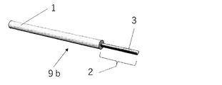
- FIG. 1 is an overall view showing an example of a cell or tissue cryopreservation jig according to the present invention.
- the cryopreservation jig 9 a has a flat sheet-like placement part 3 formed on a gripping part 1 and a flat sheet-like support 2.
- the grip 1 is preferably made of a liquid nitrogen resistant material.
- a liquid nitrogen resistant material for example, various metals such as aluminum, iron, copper, and stainless steel, ABS resin, polypropylene resin, polyethylene resin, fluorine resin, various engineer plastics, and glass can be preferably used.
- the grip portion 1 has a cylindrical shape, but its shape is arbitrary. Further, as will be described later, a cell or tissue may not be directly contacted with liquid nitrogen, or the mounting part 3 may be covered with a cap for the purpose of protection. In this case, the grip part 1 is placed on the mounting part 3. It is also possible to improve workability when the cap is put on by making the shape of the cylinder continuously smaller from the side having no mounting toward the side having the mounting portion 3.
- the support 2 can be connected to the grip portion 1 by insert molding when molding. Furthermore, a structure insertion portion (not shown) can be produced in the grip portion 1 and the support 2 can be connected with an adhesive.
- adhesives silicone-based or fluorine-based adhesives that are resistant to low temperatures can be suitably used.
- FIG. 2 is an overall view showing another example of the cell or tissue cryopreservation jig of the present invention.
- the cryopreservation jig 9 b includes a holding part 1, a V-shaped sheet-like support 2, and a V-shaped sheet-like placement part 3 formed on the support 2.
- FIG. 3 is an overall view showing another example of the jig for cryopreservation of cells or tissues of the present invention.
- the cryopreservation jig 9 c has a grip portion 1 and a sheet-like support 2 having a curvature, and a sheet-like placement portion 3 having a curvature formed on the support 2. Similar to the cryopreservation jig in FIG. 2, workability when removing excess storage solution with a pipette or the like by dropping and attaching cells or tissue and storage solution to the center of the sheet-like mounting portion 3 having a curvature. Will improve.
- FIG. 4 is a schematic cross-sectional view showing an example of a placement portion in the jig for cryopreservation of cells or tissues of the present invention.
- the mounting part 3a in FIG. 4 has a convex part 4 for holding cells or tissues and a concave part 5 for storing a preservation solution.
- FIG. 5 is a schematic cross-sectional structure diagram showing another example of the placement portion in the cell or tissue cryopreservation jig of the present invention.
- the mounting part 3b in FIG. 5 has a convex part 4 for holding cells or tissues whose apex part is flat, and a concave part 5 for storing a preservation solution.
- the contact area with the cell or tissue to be placed increases, so that the cell or tissue can be held more reliably.
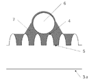
- FIG. 6 is a model diagram when the cells and the preservation solution are dropped and attached to the mounting portion shown in FIG.
- the mounting portion 3 a has a convex portion 4 that holds cells or tissues and a concave portion 5 that stores a preservation solution.
- the cells 6 shown in FIG. 6 are placed on the placement portion 3a together with the preservation solution 7.
- the cell 6 has the preservation solution 7 around its outer periphery, and is reliably held by the convex portion 4 through the preservation solution 7.
- other excess vitrification liquid is stored in the recess 5 while leaving a small amount of the preservation liquid 7 on the outer periphery of the cell 6.
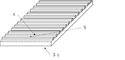
- FIG. 7 is a perspective view showing an example of a placement portion in the jig for cryopreservation of cells or tissues of the present invention.
- the mounting part 3c shown in FIG. 7 has a convex part 4 for holding cells or tissues whose apex part is flat, and a concave part 5 for storing a preservation solution.
- the entire mounting portion has a uniform pattern in a line and space shape (so-called stripe shape).
- FIG. 8 is a perspective view showing another example of the placement portion in the jig for cryopreservation of cells or tissues of the present invention.
- the mounting unit 3d shown in FIG. 8 has a structure having a cylindrical (so-called pillar-shaped) structure as a uniform pattern as the entire mounting unit. It has the convex part 4 which hold
- the recessed part 5 has the structure connected in the whole mounting part, and can store more excess preservation
- FIG. 9 is a perspective view showing another example of a placement portion in the cell or tissue cryopreservation jig of the present invention.
- the mounting unit 3e shown in FIG. 9 has a substantially quadrangular pyramid-shaped structure having a top as a uniform pattern on the entire mounting unit toward the upper surface (the cell or tissue mounting side) of the mounting unit. Structure. It has a substantially quadrangular pyramid-shaped convex part 4 and a concave part 5 for storing a preservation solution. Since the area where the cell or tissue is in contact with each convex portion is small, easy detachment and recovery are possible when the frozen cell or tissue is thawed.
- FIG. 10 is a perspective view showing another example of a placement portion in the cell or tissue cryopreservation jig of the present invention.
- the mounting portion 3 f shown in FIG. 10 has a substantially quadrangular pyramid-shaped structure having a top toward the upper surface (cell or tissue mounting side) of the mounting portion.
- the density of the substantially quadrangular pyramid-shaped structure is lower than that of FIG. 9 compared to FIG. 9. ing.
- the concave portion 5 can store a larger amount of the storage solution, and therefore when cells or tissues are dropped onto the placement portion during the freezing operation. In addition, it is possible to cope with a case where more preservation solution is dropped and adhered.
- FIG. 11 is a perspective view showing another example of a placement portion in the cell or tissue cryopreservation jig of the present invention.
- the mounting portion 3g shown in FIG. 11 has a cylindrical structure, and has a cylindrical convex portion 4 and a concave portion 5 for storing a storage liquid.
- the cylindrical structure is an example having a non-uniform pattern (random pattern) for each region of the placement unit.
- FIG. 12 is a cross-sectional structure diagram showing an example of a placement portion when the cell or tissue cryopreservation jig of the present invention has a preservation solution absorber.
- the mounting portion 3 h has a storage liquid absorber 8 on the support 2.
- the preservation solution absorber 8 has a convex portion 4 for holding cells or tissues and a concave portion 5 for storing a preservation solution.
- the placement unit 3h securely holds the cell or tissue by the convex portion 4 and stores the preservation solution in the concave portion 5 as well as the cell or tissue. Since the extra storage solution on the outer periphery of the substrate is removed by the storage solution absorber 8, rapid vitrification freezing can be performed without requiring an operation of removing the extra storage solution with a pipette or the like.
- FIG. 13 is a model diagram when the cells and the preservation solution are dropped and attached to the mounting portion shown in FIG.
- the preservation liquid absorber 8 has a convex part 4 that holds cells or tissues and a concave part 5 that stores the preservation liquid.
- the cells 6 shown in FIG. 13 are placed on the preservation solution absorber 8 together with the preservation solution 7.
- the cell 6 has the preservation solution 7 around its outer periphery, and is reliably held by the convex portion 4 through the preservation solution 7.
- the storage solution absorber 8 is excessive.
- rapid vitrification freezing can be performed without requiring an operation for removing excess preservation solution with a pipette or the like. Furthermore, the excess preservation solution can be removed more reliably.
- the height and pattern pitch of the convex portions formed on the mounting portion were measured using a confocal microscope Optics (registered trademark) C130 manufactured by Lasertec Corporation.
- Example 1 A structure in which a square pyramid shape having a height of 5 ⁇ m and a pattern pitch of 50 ⁇ m is uniformly arranged in a specific region of a transparent PET film that is a non-absorbent material by a thermal transfer process using an embossing press machine is produced.
- save liquid was obtained.
- the transparent PET film including the prepared placement area was cut into a 1.5 mm ⁇ 20 mm strip and joined to an ABS gripping part to prepare the cryopreservation jig of Example 1.
- Example 2 A structure in which hexagonal prism shapes having a height of 1 ⁇ m and a pattern pitch of 10 ⁇ m are uniformly arranged in a specific region of a non-absorbent transparent PET film by pressure transfer processing using an embossing press machine is produced.
- save liquid was obtained. Thereafter, in the same manner as in Example 1, it was joined to an ABS gripping part to produce a cryopreservation jig of Example 2.
- Example 3 A polytetrafluoroethylene porous material (pore diameter 0.2 ⁇ m, porosity 71%, thickness 35 ⁇ m) manufactured by Advantech Toyo Co., Ltd. was used as a preservative solution absorber. A structure in which a quadrangular pyramid shape having a thickness of 5 ⁇ m and a pattern pitch of 50 ⁇ m was uniformly arranged was produced, and a mounting portion having a convex portion for holding cells or tissues and a concave portion for storing a preservation solution was obtained. Further, a transparent PET film is used as a support, and a hot melt urethane resin Purmelt (registered trademark) QR 170-7141P manufactured by Henkel Japan Co., Ltd.
- a hot melt urethane resin Purmelt registered trademark
- Example 3 is used as an adhesive layer on the support.
- the solid content upon drying is 30 g / m 2. It applied so that it might become.
- the surface of the storage liquid absorber that had been subjected to the thermal transfer process by the above-described method was bonded to the support on the side having no surface structure. Then, the paste of the preservative solution absorber and the support including the region of the prepared mounting part was cut into a 1.5 mm ⁇ 20 mm strip, joined to the ABS grip part, and used for cryopreservation of Example 3 A jig was produced.
- Example 4 In the same manner as in Example 3 described above, a bonded product of a storage liquid absorber and a support having a structure made up of convex portions and concave portions on the mounting portion was obtained. Thereafter, the bonded product was dip-coated with a 2% by weight aqueous solution of GOHSEX (registered trademark) WO-320R, which is a polyvinyl alcohol having an ethylene oxide group, which is a water-soluble polymer, dried at room temperature, and further at 120 ° C. Heat drying was performed for 40 hours. The application amount of the water-soluble polymer was 1.6 g / m 2 .
- GOHSEX registered trademark
- WO-320R which is a polyvinyl alcohol having an ethylene oxide group, which is a water-soluble polymer
- Example 4 Thereafter, the pasted product coated with the water-soluble polymer was cut into a 1.5 mm ⁇ 20 mm strip in the same manner as in Example 1, joined to the ABS gripping part, and used for cryopreservation in Example 4. A jig was produced.
- Example 5 The jig for cryopreservation of Example 5 is produced in the same manner as in Example 4 except that a structure in which a quadrangular pyramid shape having a height of 1 ⁇ m and a pattern pitch of 50 ⁇ m is uniformly arranged is produced by pressure transfer processing. did.
- Comparative Example 1 A cryopreservation jig of Comparative Example 1 was produced in the same manner as in Example 1 except that the surface treatment was not performed on the transparent PET film that was a non-absorbent.
- Comparative Example 2 A cryopreservation jig of Comparative Example 2 was produced in the same manner as in Example 3 except that the surface treatment was not performed on the polytetrafluoroethylene porous material.
- spheres used for evaluation of cell or tissue detachability were prepared as follows. Mouse embryonic fibroblasts were cultured on a culture dish and then detached and collected by trypsin treatment. Subsequently, sphere formation was induced by seeding on a PrimeSurface (registered trademark) 96U plate manufactured by Sumitomo Bakelite Co., Ltd. at a cell number of 50 cells / well and suspension culture. After 3 days of culture, spheres having a diameter of about 100 ⁇ m were obtained.
- PrimeSurface registered trademark
- the spheres are collected together with a small amount of vitrification preservation solution (approximately 0.4 ⁇ l), and the cryopreservation jigs of Examples 1 to 5 and Comparative Example 1 are placed. Each part was dropped and adhered.
- the cryopreservation jigs of Examples 1 and 2 and Comparative Example 1 that do not have a preservative solution absorber one sphere was dropped onto the mounting portion together with a small amount of vitrification preservative, and then permeated.
- cryopreservation jigs of Examples 3 to 5 and Comparative Example 2 having the preservation solution absorber one sphere was dropped and attached together with a small amount of vitrification preservation solution, and then the excess was measured with a transmission microscope. While observing the spontaneous absorption of the vitrification solution, make sure that excess vitrification solution has been removed from the periphery of the sphere, soak it in liquid nitrogen, and remove the sphere on the mounting part. Vitrified and frozen. The frozen cryopreservation jig was stored in a liquid nitrogen storage container until thawed.
- the operability during the above freezing operation was as follows.
- the cryopreservation jigs of Examples 1 and 2 that do not have a preservative solution absorber as compared with Comparative Example 1, when the spheres were dropped onto the mounting portion together with a small amount of vitrification preservative solution, The vitrification preservative solution and the sphere were likely to adhere to the surface of the placement portion, and the work of dropping and attaching the sphere onto the placement portion was easy.
- the cryopreservation jigs of Examples 1 and 2 have the vitrification preservative solution stored in the recesses on the placement unit, and glass on the placement unit surface.
- the vitrification storage solution Since the vitrification storage solution is easy to adhere, it was easy to extend the excess vitrification solution with the tip of the pipette and to remove the excess vitrification solution.
- the vitrification preservation solution is absorbed by the preservation solution absorber when dropped and attached.
- the work of attaching to the surface of the mounting part is uniformly easy, and further, the work of removing excess storage solution using a pipette or the like is not required, and the operability in the freezing work is uniformly good. there were.
- the peelability of cells or tissues was evaluated according to the following criteria.
- the cryopreservation jig of the present invention can easily remove excess storage solution around the cell or tissue when the cell or tissue is dropped onto the placement part in the freezing operation. It can be seen that the cell or tissue can be reliably held on the surface of the mounting portion, and further, the cell or tissue can be quickly recovered in the melting operation.
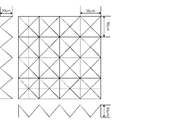
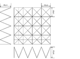
- Example 6 As a polyethylene terephthalate film, a square pyramid shape having a side length of 50 ⁇ m and a height of 30 ⁇ m shown in FIG. 14 on Lumirror (registered trademark) T60 (thickness: 188 ⁇ m, total light transmittance: 91%) manufactured by Toray Industries, Inc. By pressing a female mold (13 ⁇ 12 cm, total thickness 130 ⁇ m) formed continuously using a roll-type embossing machine, EMBOSTAR (registered trademark), manufactured by Cyto Engineering Co., Ltd., A convex portion was formed on one surface of the polyethylene terephthalate film.
- Lumirror registered trademark
- T60 thickness: 188 ⁇ m, total light transmittance: 91%) manufactured by Toray Industries, Inc.
- EMBOSTAR registered trademark
- This machine is an embossing machine that performs uneven processing by passing a workpiece between two rolls with adjustable gaps. Adjusting the depth of processing on the target by adjusting the gap between rolls and the processing temperature. Is possible.
- the gap between rolls was 320 ⁇ m.
- the temperature at the time of processing was 240 ° C.
- the height of the convex part formed on the polyethylene terephthalate film processed on said conditions was 5 micrometers, and the pattern pitch of the convex part was 50 micrometers.
- the obtained concavo-convex-processed polyethylene terephthalate film was cut into a rectangle having a short side of 1.5 mm and a long side of 25.0 mm, joined to a gripping part made of ABS resin, and used for cryopreservation of Example 6 in the form shown in FIG. A jig was produced.
- Example 7 In Example 6, the cryopreservation jig of Example 7 was produced in the same manner except that the press working was performed with the gap between rolls set to 310 ⁇ m. In Example 7, the height of the convex portions formed on the polyethylene terephthalate film was 14 ⁇ m, and the pattern pitch of the convex portions was 50 ⁇ m.
- Example 8 In Example 6, a cryopreservation jig of Example 8 was produced in the same manner except that the press working was performed with the gap between rolls set to 300 ⁇ m. In Example 8, the height of the convex portions formed on the polyethylene terephthalate film was 22 ⁇ m, and the pattern pitch of the convex portions was 50 ⁇ m.
- Example 9 In Example 6, the cryopreservation jig of Example 9 was produced in the same manner except that the press working was performed with the gap between rolls being 290 ⁇ m. In Example 9, the height of the convex portions formed on the polyethylene terephthalate film was 27 ⁇ m, and the pattern pitch of the convex portions was 50 ⁇ m.
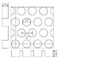
- Example 10 Using a female die (13 ⁇ 12 cm, total thickness 300 ⁇ m) in which a quadrangular pyramid shape with a side length of 50 ⁇ m and a height of 60 ⁇ m shown in FIG. 15 is used, press the gap between rolls to 450 ⁇ m.
- a cryopreservation jig of Example 10 was produced in the same manner as in Example 6 except that it was processed.
- the height of the convex portions formed on the polyethylene terephthalate film was 46 ⁇ m, and the pattern pitch of the convex portions was 50 ⁇ m.
- Comparative Example 3 As a polyethylene terephthalate film, Lumirror (registered trademark) T60 (thickness: 188 ⁇ m) manufactured by Toray Industries, Inc. is cut into a rectangle with a short side of 1.5 mm and a long side of 25.0 mm, and bonded to a gripping part made of ABS resin. A jig for cryopreservation of Comparative Example 3 was produced in the form shown in FIG.
- A When the cryopreservation jig was immersed in the melt, the mouse egg could be peeled off in less than 30 seconds by gently shaking the grip.
- ⁇ When the cryopreservation jig was immersed in the melting solution, the mouse egg could be peeled off within 30 to 60 seconds by gently shaking the grip.
- ⁇ When the cryopreservation jig was immersed in the melting solution, peeling was not possible even if the gripping portion was gently shaken, and when it was shaken strongly, the mouse egg could be peeled off.
- X When the cryopreservation jig was immersed in the melt, the mouse egg could not be peeled even if the gripping part was gently shaken or strongly shaken.
- spheres used for evaluation of cell or tissue detachability were prepared as follows. Mouse embryonic fibroblasts were cultured on a culture dish and then detached and collected by trypsin treatment. Subsequently, sphere formation was induced by seeding on a PrimeSurface (registered trademark) 96U plate manufactured by Sumitomo Bakelite Co., Ltd. at a cell number of 50 cells / well and suspension culture. After about 40 hours of culture, spheres having a diameter of 50 ⁇ m were obtained.
- PrimeSurface registered trademark
- ⁇ Freezing work of sphere> A sphere having a diameter of 50 ⁇ m was immersed in a Vit Kit equilibrium solution manufactured by Irvine Scientific having a liquid temperature of 15 ° C. Next, the spheres after immersion in the equilibrium solution were immersed in a Vit Kit (registered trademark) vitrification solution manufactured by Irvine Scientific having a liquid temperature of 4 ° C. After immersing in the vitrification solution for 90 seconds, place one sphere on the placement part of the cryopreservation jig (Examples 6 to 10 and Comparative Example 3) using a pipette under a transmission microscope. did. At this time, the excess vitrification liquid which exists in a mounting part was removed by pipette operation. Thereafter, the above-mentioned cryopreservation jig was immersed in liquid nitrogen and frozen by vitrification. The frozen storage jig after freezing was stored in a liquid nitrogen storage container.
- Example 11 A polytetrafluoroethylene porous material (pore size 0.2 ⁇ m, porosity 71%, thickness 35 ⁇ m) manufactured by Advantech Toyo Co., Ltd. is cut into a 20 cm ⁇ 10 cm strip shape using a pressing cutter, and then the cut porous The body was placed on a polycarbonate film having a thickness of 300 ⁇ m. On a porous body placed on a polycarbonate film, a female mold (13 ⁇ 12 cm, total thickness, shown in FIG. 14) in which a quadrangular pyramid shape having a side length of 50 ⁇ m and a height of 30 ⁇ m is continuously formed.
- a hot melt urethane resin Purmelt manufactured by Henkel Japan Co., Ltd.
- Lumirror registered trademark
- T60 thickness: 188 ⁇ m
- QR 170-7141P was applied so that the solid content at the time of drying was 30 g / m 2 .
- Example 11 the height of the convex portions formed on the porous body was 3 ⁇ m, and the pattern pitch of the convex portions was 50 ⁇ m.
- Example 12 A cryopreservation jig of Example 12 was produced in the same manner as in Example 11 except that the press working was performed with the gap between rolls being 490 ⁇ m.
- the height of the convex portions formed on the porous body was 5 ⁇ m, and the pattern pitch of the convex portions was 50 ⁇ m.
- Example 13 In Example 11, a cryopreservation jig of Example 13 was produced in the same manner except that the press working was performed with the gap between rolls being 470 ⁇ m. In Example 13, the height of the convex portions formed on the porous body was 9 ⁇ m, and the pattern pitch of the convex portions was 50 ⁇ m.
- Example 14 A cryopreservation jig of Example 14 was produced in the same manner as in Example 11, except that the press working was performed with the gap between rolls set to 450 ⁇ m.
- the height of the convex portions formed on the porous body was 12 ⁇ m, and the pattern pitch of the convex portions was 50 ⁇ m.
- Example 15 In Example 11, a cryopreservation jig of Example 15 was produced in the same manner except that the press working was performed with the gap between rolls set to 430 ⁇ m. In Example 15, when the height of the convex portions formed on the porous body was observed with an electron microscope, the height of the convex portions was 16 ⁇ m and the pattern pitch of the convex portions was 50 ⁇ m.
- Example 16 In Example 11, a female mold (outer shape 13 ⁇ 13 cm (pattern formation) in which a cylindrical shape with a diameter of 1.4 to 2.0 ⁇ m shown in FIG. 16 was continuously formed with a pattern pitch of 2.7 to 3.3 ⁇ m.
- the jig for cryopreservation of Example 16 was manufactured in the same manner as in Example 16 except that the pressing was performed with a gap between rolls of 540 ⁇ m using a part area of 7 ⁇ 7 cm) and a total thickness of 190 ⁇ m.
- the height of the convex portions formed on the porous body was 1.2 ⁇ m, and the pattern pitch of the convex portions was 3.0 ⁇ m.
- Example 17 In Example 16, instead of the female mold shown in FIG. 16, a cylindrical shape having a diameter of 1.4 to 2.0 ⁇ m shown in FIG. 17 is continuously formed with a pattern pitch of 2.7 to 3.3 ⁇ m. Using the male mold (outer shape 13 ⁇ 13 cm (pattern forming area 7 ⁇ 7 cm), total thickness 190 ⁇ m), the same processing was performed except that it was pressed, and the cryopreservation jig of Example 17 was produced. did. In Example 17, the height of the convex portions formed on the porous body was 1.1 ⁇ m, and the pattern pitch of the convex portions was 3.0 ⁇ m.
- Example 18 The cryopreservation jig of Example 18 was produced in the same manner except that a soluble layer was provided on the placement part of the cryopreservation jig obtained in Example 11.
- the soluble layer was dip-coated with a 2% by weight aqueous solution of Gosennex (registered trademark) WO-320R (saponification degree: 88.3 mol%) manufactured by Nippon Synthetic Chemical Industry, and dried at room temperature. The heat treatment was performed at 40 ° C. for 40 hours.
- the height of the convex portions formed on the porous body was 2.9 ⁇ m, and the pattern pitch of the convex portions was 50 ⁇ m.
- Example 19 In the same manner as in Example 18, a soluble layer was provided on the placement part of the cryopreservation jig obtained in Example 12, and the cryopreservation jig of Example 19 was produced.
- the height of the convex portions formed on the porous body was 4.9 ⁇ m, and the pattern pitch of the convex portions was 50 ⁇ m.
- Comparative Example 4 A cryopreservation jig of Comparative Example 4 was produced in the same manner as in Example 11 except that a polytetrafluoroethylene porous material manufactured by Advantech Toyo Co., Ltd., which had no protrusions, was used as the mounting portion.
- the peelability of the cells or tissues was evaluated by the same method and standard as the evaluation of the peelability of cells or tissues using mouse eggs having a diameter of 100 ⁇ m described above. The results are shown in Table 4.
- Example 20 A transparent PET film (total light transmittance 91%, haze value 5.5%) subjected to easy adhesion treatment is used as a support, and a hot melt urethane resin Purmelt manufactured by Henkel Japan Co., Ltd. is used as an adhesive layer on the support. (Registered Trademark) QR 170-7141P was applied so that the solid content upon drying was 30 g / m 2 . Before the adhesive layer was completely cured, the non-roughened surface of the preservation solution absorber having one surface roughened by the following method was bonded to the adhesive layer.
- One side of the preservation solution absorber having one surface roughened is a polytetrafluoroethylene porous material (pore size 0.2 ⁇ m, porosity 71%, thickness 35 ⁇ m) manufactured by Advantech Toyo Co., Ltd.
- a fine mold having a surface in which square pyramids having a height of 50 ⁇ m and a height of 25 ⁇ m are arranged in a grid pattern is obtained in a range of 4 cm ⁇ 8 cm, a surface pressure of 1.64 kN, a temperature of 120 ° C., a pressure and a heating time of 2 It was obtained by carrying out a pressure heat transfer process with an embossing press under the condition of minutes.
- the surface of the obtained storage liquid absorber having convex and concave portions is dip-coated with a 2% by mass aqueous solution of Kuraray Co., Ltd. PVA103 (saponification degree: 98.5 mol%), dried at room temperature, and then 120 ° C. Then, a heat treatment was performed for 40 hours to form a soluble layer.
- Ra of the surface of the mounting portion was 1.69 ⁇ m as measured by Surfcom (registered trademark) 1400D manufactured by Tokyo Seimitsu Co., Ltd.
- the solid content of the soluble layer was 1.6 g / m 2 .
- the size of the mounting portion formed on the support is 1.5 mm ⁇ 5 mm.
- Example 21 In the production of the cryopreservation jig of Example 20, the cryopreservation jig of Example 21 was the same as Example 20, except that the soluble layer was not provided on the roughened polytetrafluoroethylene porous body. Was made. In addition, it was 2.20 micrometers when Ra on the surface of a mounting part was measured by Surfcom (trademark) 1400D by Tokyo Seimitsu Co., Ltd.
- Example 22 In the production of the cryopreservation jig of Example 20, the surface pressure during pressure heat transfer was increased to 2.87 kN, and the cryopreservation jig was produced as Example 22. In addition, it was 3.12 micrometers when Ra of the mounting surface was measured by Surfcom (registered trademark) 1400D manufactured by Tokyo Seimitsu Co., Ltd.
- ⁇ Freezing mouse embryo> A mouse embryo having a diameter of about 100 ⁇ m was stored in a stock solution (15% by volume DMSO (dimethyl sulfoxide), 15% by volume ethylene glycol, 14% by volume fetal calf serum, 56% by volume corrected phosphate buffer (137 mM)).
- the pitch of the protrusions formed on the mounting portion of the cryopreservation jig used for the above-described mouse embryo freezing operation, and the above-described mouse embryo melting operation and peelability evaluation is as described in Examples 20 to 20. It was 50 micrometers in any of 22.
- the peelability of cells or tissues was evaluated according to the following criteria.
- ⁇ When the cryopreservation jig was immersed in the melt, it took 40 seconds to less than 60 seconds to peel off the mouse embryo while shaking the gripping portion.
- cryopreservation jig of the present invention exhibits excellent peelability upon melting.
- the present invention is a test collected from a living body including an iPS cell, an ES cell, a commonly used cultured cell, an embryo, or an egg in addition to an embryo transfer or artificial insemination of a domestic animal such as a cow or an animal, artificial insemination to a human, etc. It can be used for cryopreservation of cells or tissues for use or transplantation, cells or tissues cultured in vitro, and the like.
Landscapes
- Life Sciences & Earth Sciences (AREA)
- Health & Medical Sciences (AREA)
- Engineering & Computer Science (AREA)
- Zoology (AREA)
- Wood Science & Technology (AREA)
- General Health & Medical Sciences (AREA)
- Chemical & Material Sciences (AREA)
- Organic Chemistry (AREA)
- Bioinformatics & Cheminformatics (AREA)
- Environmental Sciences (AREA)
- Dentistry (AREA)
- Genetics & Genomics (AREA)
- Biomedical Technology (AREA)
- Mechanical Engineering (AREA)
- Biochemistry (AREA)
- Biotechnology (AREA)
- Microbiology (AREA)
- Sustainable Development (AREA)
- General Engineering & Computer Science (AREA)
- Hematology (AREA)
- Molecular Biology (AREA)
- Clinical Laboratory Science (AREA)
- Thermal Sciences (AREA)
- Physics & Mathematics (AREA)
- Apparatus Associated With Microorganisms And Enzymes (AREA)
- Micro-Organisms Or Cultivation Processes Thereof (AREA)
Priority Applications (4)
| Application Number | Priority Date | Filing Date | Title |
|---|---|---|---|
| EP18818541.7A EP3640320A4 (en) | 2017-06-12 | 2018-06-08 | Cryopreservation device for the cryopreservation of cells or tissues |
| JP2019525393A JP6768955B2 (ja) | 2017-06-12 | 2018-06-08 | 細胞又は組織の凍結保存用治具 |
| KR1020197035776A KR102288612B1 (ko) | 2017-06-12 | 2018-06-08 | 세포 또는 조직의 동결 보존용 지그 |
| US16/621,337 US11510408B2 (en) | 2017-06-12 | 2018-06-08 | Cryopreservation jig for cryopreserving cells or tissues |
Applications Claiming Priority (6)
| Application Number | Priority Date | Filing Date | Title |
|---|---|---|---|
| JP2017-114822 | 2017-06-12 | ||
| JP2017114822 | 2017-06-12 | ||
| JP2018032654 | 2018-02-27 | ||
| JP2018-032654 | 2018-02-27 | ||
| JP2018-056780 | 2018-03-23 | ||
| JP2018056780 | 2018-03-23 |
Publications (1)
| Publication Number | Publication Date |
|---|---|
| WO2018230477A1 true WO2018230477A1 (ja) | 2018-12-20 |
Family
ID=64659911
Family Applications (1)
| Application Number | Title | Priority Date | Filing Date |
|---|---|---|---|
| PCT/JP2018/022105 WO2018230477A1 (ja) | 2017-06-12 | 2018-06-08 | 細胞又は組織の凍結保存用治具 |
Country Status (5)
| Country | Link |
|---|---|
| US (1) | US11510408B2 (ko) |
| EP (1) | EP3640320A4 (ko) |
| JP (1) | JP6768955B2 (ko) |
| KR (1) | KR102288612B1 (ko) |
| WO (1) | WO2018230477A1 (ko) |
Cited By (3)
| Publication number | Priority date | Publication date | Assignee | Title |
|---|---|---|---|---|
| JPWO2019004300A1 (ja) * | 2017-06-30 | 2020-04-30 | 株式会社北里コーポレーション | 生体細胞凍結保存具および生体細胞凍結保存用具 |
| JP2020103224A (ja) * | 2018-12-28 | 2020-07-09 | 三菱製紙株式会社 | 凍結保存用治具 |
| JP2020171223A (ja) * | 2019-04-10 | 2020-10-22 | 三菱製紙株式会社 | 凍結保存用治具 |
Families Citing this family (2)
| Publication number | Priority date | Publication date | Assignee | Title |
|---|---|---|---|---|
| CN209331001U (zh) * | 2018-11-09 | 2019-09-03 | 彭秋平 | 冷冻载杆 |
| USD970746S1 (en) * | 2020-06-25 | 2022-11-22 | Mitsubishi Paper Mills Limited | Stage for cell cryopreservation operation |
Citations (20)
| Publication number | Priority date | Publication date | Assignee | Title |
|---|---|---|---|---|
| JPS4213560B1 (ko) | 1963-11-01 | 1967-08-01 | ||
| JPH08283447A (ja) | 1995-04-14 | 1996-10-29 | Sumitomo Electric Ind Ltd | 親水性四弗化エチレン樹脂多孔質膜及びその製造方法 |
| JP3044323B1 (ja) | 1999-01-07 | 2000-05-22 | 農林水産省畜産試験場長 | 細胞の凍結保存方法 |
| JP2002160930A (ja) | 2000-11-24 | 2002-06-04 | Toshiba Ceramics Co Ltd | 多孔質石英ガラスとその製造方法 |
| JP2002315573A (ja) | 2001-04-18 | 2002-10-29 | Kitazato Supply:Co Ltd | 卵凍結保存用具および筒状部材保持器具 |
| WO2006041118A1 (ja) | 2004-10-15 | 2006-04-20 | Taisei Kogyo Co., Ltd. | 多孔質焼結体の製造方法、多孔質焼結成形材料及び多孔質焼結体 |
| JP2006271395A (ja) | 2006-06-13 | 2006-10-12 | Kitazato Supply:Co Ltd | 卵凍結保存用具 |
| JP2008005846A (ja) | 1995-06-07 | 2008-01-17 | Phyton Inc | 多様な植物細胞の凍結保存方法 |
| JP2009029692A (ja) | 2007-06-28 | 2009-02-12 | Covalent Materials Corp | 焼成用道具材およびその製造方法 |
| JP2009235417A (ja) | 2001-08-02 | 2009-10-15 | Asahi Kasei Chemicals Corp | 焼結体および樹脂粒子の製造方法 |
| JP4578062B2 (ja) | 2003-04-09 | 2010-11-10 | 太盛工業株式会社 | 粉体焼結成形体の製造方法、焼結材料成形体の製造方法、焼結材料成形体及び粉体射出成形用金型装置 |
| WO2011070973A1 (ja) | 2009-12-08 | 2011-06-16 | 学校法人北里研究所 | 動物の胚または卵子のガラス化保存用細管 |
| JP2012205516A (ja) | 2011-03-29 | 2012-10-25 | Osaka Univ | 人工皮膚モデルの製造方法、及び人工皮膚モデル |
| JP2014183757A (ja) | 2013-03-22 | 2014-10-02 | Kitasato Institute | 卵子又は胚のガラス化凍結保存用治具 |
| WO2015064380A1 (ja) | 2013-10-29 | 2015-05-07 | 学校法人北里研究所 | 細胞または組織のガラス化凍結保存用治具 |
| JP2015142523A (ja) | 2014-01-31 | 2015-08-06 | 三菱製紙株式会社 | 細胞または組織のガラス化凍結保存用治具 |
| JP5781621B2 (ja) | 2011-10-03 | 2015-09-24 | 株式会社北里バイオファルマ | 生体細胞凍結保存具 |
| JP5798633B2 (ja) | 2011-10-04 | 2015-10-21 | 株式会社北里バイオファルマ | 細胞凍結保存用具 |
| JP2015226497A (ja) | 2014-05-30 | 2015-12-17 | 大日本印刷株式会社 | 細胞容器、細胞収納装置、細胞収納装置の外装体、細胞収納装置の使用方法 |
| JP2017060457A (ja) | 2014-10-23 | 2017-03-30 | 三菱製紙株式会社 | 細胞又は組織の凍結保存用治具および凍結保存方法 |
Family Cites Families (11)
| Publication number | Priority date | Publication date | Assignee | Title |
|---|---|---|---|---|
| US5310674A (en) | 1982-05-10 | 1994-05-10 | Bar-Ilan University | Apertured cell carrier |
| JP3202359B2 (ja) * | 1992-11-19 | 2001-08-27 | 株式会社東芝 | 遠隔監視装置 |
| JP3044323U (ja) | 1997-06-12 | 1997-12-22 | 船井電機株式会社 | 空気清浄装置付き空気調和機 |
| JP5224703B2 (ja) * | 2007-03-13 | 2013-07-03 | 株式会社北里バイオファルマ | 採取組織片ガラス化凍結保存用具、組織片凍結保存用プレートおよび採取組織片ガラス化凍結保存方法 |
| ES2743693T3 (es) * | 2009-04-29 | 2020-02-20 | Biolife Solutions Inc | Aparatos y composiciones para crioconservación de monocapas celulares |
| JP5935313B2 (ja) * | 2010-12-17 | 2016-06-15 | ニプロ株式会社 | 凍結保存器具 |
| JP5920296B2 (ja) | 2013-09-03 | 2016-05-18 | 大日本印刷株式会社 | 細胞培養容器 |
| JP6124845B2 (ja) * | 2014-06-30 | 2017-05-10 | 三菱製紙株式会社 | 細胞又は組織のガラス化凍結保存用治具 |
| WO2016031916A1 (ja) * | 2014-08-29 | 2016-03-03 | 株式会社北里バイオファルマ | 採取生体組織凍結保存用具および組織片凍結保存方法 |
| EP3243900B1 (en) * | 2015-01-09 | 2020-12-16 | Meiji University | Hollow fiber cryopreservation instrument and cell cryopreservation method |
| JP3202359U (ja) | 2015-11-19 | 2016-01-28 | 三菱製紙株式会社 | 細胞又は組織の凍結保存用治具 |
-
2018
- 2018-06-08 EP EP18818541.7A patent/EP3640320A4/en not_active Withdrawn
- 2018-06-08 US US16/621,337 patent/US11510408B2/en active Active
- 2018-06-08 JP JP2019525393A patent/JP6768955B2/ja active Active
- 2018-06-08 WO PCT/JP2018/022105 patent/WO2018230477A1/ja unknown
- 2018-06-08 KR KR1020197035776A patent/KR102288612B1/ko active IP Right Grant
Patent Citations (20)
| Publication number | Priority date | Publication date | Assignee | Title |
|---|---|---|---|---|
| JPS4213560B1 (ko) | 1963-11-01 | 1967-08-01 | ||
| JPH08283447A (ja) | 1995-04-14 | 1996-10-29 | Sumitomo Electric Ind Ltd | 親水性四弗化エチレン樹脂多孔質膜及びその製造方法 |
| JP2008005846A (ja) | 1995-06-07 | 2008-01-17 | Phyton Inc | 多様な植物細胞の凍結保存方法 |
| JP3044323B1 (ja) | 1999-01-07 | 2000-05-22 | 農林水産省畜産試験場長 | 細胞の凍結保存方法 |
| JP2002160930A (ja) | 2000-11-24 | 2002-06-04 | Toshiba Ceramics Co Ltd | 多孔質石英ガラスとその製造方法 |
| JP2002315573A (ja) | 2001-04-18 | 2002-10-29 | Kitazato Supply:Co Ltd | 卵凍結保存用具および筒状部材保持器具 |
| JP2009235417A (ja) | 2001-08-02 | 2009-10-15 | Asahi Kasei Chemicals Corp | 焼結体および樹脂粒子の製造方法 |
| JP4578062B2 (ja) | 2003-04-09 | 2010-11-10 | 太盛工業株式会社 | 粉体焼結成形体の製造方法、焼結材料成形体の製造方法、焼結材料成形体及び粉体射出成形用金型装置 |
| WO2006041118A1 (ja) | 2004-10-15 | 2006-04-20 | Taisei Kogyo Co., Ltd. | 多孔質焼結体の製造方法、多孔質焼結成形材料及び多孔質焼結体 |
| JP2006271395A (ja) | 2006-06-13 | 2006-10-12 | Kitazato Supply:Co Ltd | 卵凍結保存用具 |
| JP2009029692A (ja) | 2007-06-28 | 2009-02-12 | Covalent Materials Corp | 焼成用道具材およびその製造方法 |
| WO2011070973A1 (ja) | 2009-12-08 | 2011-06-16 | 学校法人北里研究所 | 動物の胚または卵子のガラス化保存用細管 |
| JP2012205516A (ja) | 2011-03-29 | 2012-10-25 | Osaka Univ | 人工皮膚モデルの製造方法、及び人工皮膚モデル |
| JP5781621B2 (ja) | 2011-10-03 | 2015-09-24 | 株式会社北里バイオファルマ | 生体細胞凍結保存具 |
| JP5798633B2 (ja) | 2011-10-04 | 2015-10-21 | 株式会社北里バイオファルマ | 細胞凍結保存用具 |
| JP2014183757A (ja) | 2013-03-22 | 2014-10-02 | Kitasato Institute | 卵子又は胚のガラス化凍結保存用治具 |
| WO2015064380A1 (ja) | 2013-10-29 | 2015-05-07 | 学校法人北里研究所 | 細胞または組織のガラス化凍結保存用治具 |
| JP2015142523A (ja) | 2014-01-31 | 2015-08-06 | 三菱製紙株式会社 | 細胞または組織のガラス化凍結保存用治具 |
| JP2015226497A (ja) | 2014-05-30 | 2015-12-17 | 大日本印刷株式会社 | 細胞容器、細胞収納装置、細胞収納装置の外装体、細胞収納装置の使用方法 |
| JP2017060457A (ja) | 2014-10-23 | 2017-03-30 | 三菱製紙株式会社 | 細胞又は組織の凍結保存用治具および凍結保存方法 |
Non-Patent Citations (2)
| Title |
|---|
| See also references of EP3640320A4 |
| STEPONKUS ET AL., NATURE, vol. 345, 1990, pages 170 - 172 |
Cited By (6)
| Publication number | Priority date | Publication date | Assignee | Title |
|---|---|---|---|---|
| JPWO2019004300A1 (ja) * | 2017-06-30 | 2020-04-30 | 株式会社北里コーポレーション | 生体細胞凍結保存具および生体細胞凍結保存用具 |
| JP7108318B2 (ja) | 2017-06-30 | 2022-07-28 | 株式会社北里コーポレーション | 生体細胞凍結保存具および生体細胞凍結保存用具 |
| JP2020103224A (ja) * | 2018-12-28 | 2020-07-09 | 三菱製紙株式会社 | 凍結保存用治具 |
| JP7030680B2 (ja) | 2018-12-28 | 2022-03-07 | 三菱製紙株式会社 | 凍結保存用治具 |
| JP2020171223A (ja) * | 2019-04-10 | 2020-10-22 | 三菱製紙株式会社 | 凍結保存用治具 |
| JP7232693B2 (ja) | 2019-04-10 | 2023-03-03 | 三菱製紙株式会社 | 凍結保存用治具 |
Also Published As
| Publication number | Publication date |
|---|---|
| JP6768955B2 (ja) | 2020-10-14 |
| JPWO2018230477A1 (ja) | 2020-04-23 |
| US11510408B2 (en) | 2022-11-29 |
| US20200113176A1 (en) | 2020-04-16 |
| EP3640320A1 (en) | 2020-04-22 |
| EP3640320A4 (en) | 2021-03-17 |
| KR102288612B1 (ko) | 2021-08-11 |
| KR20200005582A (ko) | 2020-01-15 |
Similar Documents
| Publication | Publication Date | Title |
|---|---|---|
| WO2018230477A1 (ja) | 細胞又は組織の凍結保存用治具 | |
| JP6230582B2 (ja) | 細胞又は組織の凍結保存用治具および凍結保存方法 | |
| KR101883813B1 (ko) | 세포 또는 조직의 유리화 동결보존용 도구 | |
| KR101988140B1 (ko) | 세포 또는 조직의 유리화 동결 보존용 지그 | |
| WO2015115313A1 (ja) | 細胞または組織のガラス化凍結保存用治具 | |
| JP2015142523A (ja) | 細胞または組織のガラス化凍結保存用治具 | |
| JP2019187244A (ja) | 細胞又は組織の凍結保存用治具 | |
| JP3202359U (ja) | 細胞又は組織の凍結保存用治具 | |
| JP2018121581A (ja) | 細胞又は組織の凍結保存用治具 | |
| JP7232693B2 (ja) | 凍結保存用治具 | |
| JP7030680B2 (ja) | 凍結保存用治具 | |
| JP6440929B2 (ja) | 細胞または組織のガラス化凍結保存用治具 | |
| JP2021136936A (ja) | 凍結保存用治具 | |
| JP2020068713A (ja) | 凍結保存用治具 | |
| JP2020039261A (ja) | 凍結保存液 | |
| JP2020145961A (ja) | 凍結保存用治具 | |
| WO2019208120A1 (ja) | 凍結保存液及び凍結保存方法 | |
| JP2015188404A (ja) | 細胞または組織のガラス化凍結保存用治具 |
Legal Events
| Date | Code | Title | Description |
|---|---|---|---|
| 121 | Ep: the epo has been informed by wipo that ep was designated in this application |
Ref document number: 18818541 Country of ref document: EP Kind code of ref document: A1 |
|
| ENP | Entry into the national phase |
Ref document number: 2019525393 Country of ref document: JP Kind code of ref document: A |
|
| ENP | Entry into the national phase |
Ref document number: 20197035776 Country of ref document: KR Kind code of ref document: A |
|
| NENP | Non-entry into the national phase |
Ref country code: DE |
|
| ENP | Entry into the national phase |
Ref document number: 2018818541 Country of ref document: EP Effective date: 20200113 |