WO2018230163A1 - コンバイン - Google Patents
コンバイン Download PDFInfo
- Publication number
- WO2018230163A1 WO2018230163A1 PCT/JP2018/016633 JP2018016633W WO2018230163A1 WO 2018230163 A1 WO2018230163 A1 WO 2018230163A1 JP 2018016633 W JP2018016633 W JP 2018016633W WO 2018230163 A1 WO2018230163 A1 WO 2018230163A1
- Authority
- WO
- WIPO (PCT)
- Prior art keywords
- pulley
- engine
- belt
- screw conveyor
- glen tank
- Prior art date
- Legal status (The legal status is an assumption and is not a legal conclusion. Google has not performed a legal analysis and makes no representation as to the accuracy of the status listed.)
- Ceased
Links
Images




Classifications
-
- A—HUMAN NECESSITIES
- A01—AGRICULTURE; FORESTRY; ANIMAL HUSBANDRY; HUNTING; TRAPPING; FISHING
- A01D—HARVESTING; MOWING
- A01D41/00—Combines, i.e. harvesters or mowers combined with threshing devices
- A01D41/02—Self-propelled combines
-
- A—HUMAN NECESSITIES
- A01—AGRICULTURE; FORESTRY; ANIMAL HUSBANDRY; HUNTING; TRAPPING; FISHING
- A01D—HARVESTING; MOWING
- A01D69/00—Driving mechanisms or parts thereof for harvesters or mowers
- A01D69/06—Gearings
-
- A—HUMAN NECESSITIES
- A01—AGRICULTURE; FORESTRY; ANIMAL HUSBANDRY; HUNTING; TRAPPING; FISHING
- A01F—PROCESSING OF HARVESTED PRODUCE; HAY OR STRAW PRESSES; DEVICES FOR STORING AGRICULTURAL OR HORTICULTURAL PRODUCE
- A01F12/00—Parts or details of threshing apparatus
- A01F12/46—Mechanical grain conveyors
-
- A—HUMAN NECESSITIES
- A01—AGRICULTURE; FORESTRY; ANIMAL HUSBANDRY; HUNTING; TRAPPING; FISHING
- A01F—PROCESSING OF HARVESTED PRODUCE; HAY OR STRAW PRESSES; DEVICES FOR STORING AGRICULTURAL OR HORTICULTURAL PRODUCE
- A01F12/00—Parts or details of threshing apparatus
- A01F12/60—Grain tanks
Definitions
- the present invention relates to a combine equipped with a transmission mechanism that transmits power from an engine.
- a combine having a function of threshing while mowing is a boarding operation unit, a mowing unit, a conveying unit that conveys the cereal from the mowing unit, a threshing device that threshs the conveyed cereal, and a threshed culm And a glen tank for collecting the selected grains.
- the shaft core of the bottom screw conveyor that sends the grains stored in the grain tank to the rear side is attached to the inner bottom of the grain tank so as to extend in the front-rear direction in the vehicle traveling direction.
- the engine that supplies power to the combine is arranged below the boarding operation unit so that its output shaft is in the left-right direction (lateral direction) in the vehicle traveling direction. The engine can extract driving force from both ends of the output shaft.
- the output end on the side that drives the traveling device, mowing unit, threshing device, sorting device, etc. is called the “main output shaft”, and the opposite side.
- the output terminal is called “auxiliary output shaft”.
- the main output shaft faces the inside of the combine, and the auxiliary output shaft faces the outside of the combine, usually facing the combine traveling direction, and is hidden under the right side cover.
- the auxiliary output shaft rotates the rotation shaft of the radiator fan, and is connected to the rotation input shaft of the bottom screw via the transmission mechanism and the bevel gear to drive power to the bottom screw. Is configured to communicate.
- a conventional transmission mechanism disclosed in Patent Document 1 includes a main pulley 13 mounted on an auxiliary output shaft 12b of an engine 12 and a rotational input shaft of a bevel gear 17 of a bottom screw 7. And a belt 15 that interlocks the two pulleys, and a tension clutch 18 that is arranged to give tension to the belt 15 and can be turned on and off by a turning lever.
- the grain tank By moving the rotating lever, disconnecting the tension clutch 18 and removing the belt 15 of the transmission mechanism, the grain tank can be pulled out in the horizontal direction or swiveled and swung to perform maintenance of the lateral portion of the threshing device. .
- each operation such as moving the rotation lever to disconnect the tension clutch and removing the belt of the transmission mechanism, from under the boarding operation part to the crawler traveling device, This is done in a narrow place where the members are dense.
- the member mounted on the Glen tank there is a slave pulley mounted on the bevel gear rotation input shaft of the bottom screw on the Glen tank side.
- a slave pulley that is as small and light as possible. If the secondary pulley can be reduced in size and weight, it is expected that the Glen tank can be moved easily, and that the work of detaching the belt of the transmission mechanism in a narrow place can be facilitated.
- an object of the present invention is to provide a combine equipped with a transmission mechanism that can realize a reduction in size and weight of the Glen tank so that the operation of moving the Glen tank is easy.
- the combine of the present invention includes an engine, a Glen tank having a bottom screw conveyor, and a transmission mechanism that transmits engine power to the bottom screw conveyor.
- the transmission mechanism includes a main pulley attached to the output shaft of the engine, a secondary pulley attached to the rotation input shaft of the bottom screw conveyor, and a first pulley that rotates in conjunction with a support base supported by the machine base. And a second pulley, a first transmission member that interlocks the main pulley and the first pulley, and a second transmission member that interlocks the second pulley and the sub pulley.
- the first pulley and the second pulley are provided between the main pulley and the sub pulley, and the first pulley and the second pulley are fixed to the machine base. It is mounted on.
- the main tank mounted on the engine output shaft can be connected to the glen tank side via the first pulley and the second pulley without any additional transmission mechanism other than the sub pulley on the glen tank side.
- the rotation of a predetermined number of rotations can be transmitted to the sub pulley.
- the rotation speed of the sub pulley can be set to an arbitrary rotation speed by appropriately setting the diameter ratio between the first pulley and the second pulley. If you want a smaller diameter and lighter weight without changing the rotation speed of the secondary pulley, you can adjust the diameter ratio of the first pulley to the second pulley so that the second pulley is smaller. It becomes.
- the glen tank can be removed or operated.
- the belt of the transmission mechanism can be easily removed, and the handling at the time of maintenance of the glen tank can be improved.
- the first transmission member is provided with a first tension clutch
- the second transmission member is provided with a second tension clutch. Both the first and second tension clutches are supported by a support base. With this configuration, when the glen tank is removed or swung, the tension clutch can be disconnected to cut the drive of the glen tank bottom screw. Even in such a case, since the first pulley is provided, if the rotation of the first pulley transmitted from the main pulley via the first transmission member is maintained, it is desired to give a rotational driving force. If there is another mechanical part, a rotational driving force can be always applied by interlocking the first pulley and the mechanical part.
- the Glen tank side can be reduced in weight and size when the Glen tank is removed or swung.
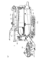
- FIG. 1 is a right side view showing the overall configuration of the combine.
- FIG. 2 is a left side view showing the overall configuration of the combine.
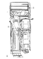
- FIG. 3 is a plan view showing the overall configuration of the combine.
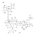
- FIG. 4 is a diagram showing a power transmission system that transmits the rotation of the auxiliary output shaft of the engine.
- FIG. 5 is a plan view showing the main structure of the combine.
- FIG. 6 is a side view showing the main structure of the combine as seen from one side in the body width direction.
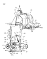
- FIG. 7 is a perspective view of main parts showing the boarding operation part and the transmission mechanism.
- FIG. 8 is a perspective view of the main part of the transmission mechanism as seen from the outside of the body.
- FIG. 9 is a perspective view of the main part of the transmission mechanism as viewed from the body side.
- FIG. 10 is a right side view of the main part showing the boarding operation part and the transmission mechanism.
- FIG. 11 is a main part plan view showing the boarding operation part and the transmission mechanism.
- FIG. 12 is a schematic diagram showing a rotational output transmission system of an engine according to the prior art.
- the combine 1 includes a machine base 2 of the combine 1 and a pair of left and right traveling crawlers 100 connected to the lower part of the machine base 2 and supporting the machine base 2, as shown in FIGS.
- the engine 30 that is mounted on the machine base 2 and supplies power to each part of the combine 1, the boarding operation part 40 that is mounted on the upper right side of the front part of the machine base 2, and can be raised and lowered in front of the machine base 2.
- a reaping unit 90 connected, a threshing device 70 for threshing the cereal grains that are arranged on the upper left side of the machine base 2 and harvested by the reaping unit 90, and a sorting device 80 for selecting the grains threshed by the threshing device 70
- a grain tank 50 that is arranged at the upper right side of the machine base 2 and on the right side of the threshing device 70 and behind the boarding operation unit 40 and stores the selected grains.
- a discharge cylinder 55 lying on the upper part of the threshing device 70 is provided in a range from the rear of the Glen tank 50 to the left front part of the combine 1.
- the engine 30, the threshing device 70, the sorting device 80, the Glen tank 50, and the like are installed inside the combine 1, and are usually surrounded by a body cover. Therefore, it is not illustrated directly in FIGS. 1 to 3, but the approximate position is indicated by a broken leader line.
- the boarding operation part 40 is arranged at the front part of the machine base 2 and on one side in the machine body width direction
- the Glen tank 50 is arranged at the rear part of the machine body 2 and on one side in the machine body width direction.
- the threshing device 70 and the sorting device 80 are arranged on the rear side of the machine base 2 and on the other side in the machine body width direction (the side opposite to the Glen tank 50).
- “one side” in the body width direction means the right side facing the forward direction of the combine 1
- “the other side” in the body width direction means the forward direction of the combine 1. It means facing the left side.
- the boarding driver 40 includes a steering member 44 disposed in front of a driver's seat 41 on which a driver can be seated, an operation lever disposed in the rear of the driver's seat 41 and for adjusting belt tension via a tension pulley.
- Various operation members such as 42 are provided.
- the engine 30 is disposed at the front of the machine base 2 and below the boarding operation unit 40.
- the direction of the engine 30 is arranged so that the output shaft of the engine 30 is parallel to the body width direction, and the driving force can be taken out from both ends of the output shaft.
- the output shaft that is taken out from the other side (inside the body) in the machine width direction is called the “main output shaft”, and the output shaft that is taken out from one side (outside the body) in the body width direction (on the opposite side of the main output shaft) Is referred to as an “auxiliary output shaft”. Since the main output shaft and the auxiliary output shaft are connected to the same crankshaft, the output can be taken out at the same rotational speed.
- the inner bottom portion of the Glen tank 50 is formed in a bowl shape, and a bottom screw conveyor 51 is arranged along the inner bottom portion of the bowl shape (along the front-rear direction of the machine base).
- a bevel gear (described later with reference to FIG. 4) for converting the direction of the rotation axis to a right angle is attached to the rotation input shaft of the bottom screw conveyor 51.
- a longitudinal feed screw conveyor 52 to which the power of the bottom screw conveyor 51 is transmitted is arranged in a substantially vertical direction at the rear of the Glen tank 50 and at the discharge end of the bottom screw conveyor 51. Further, a conveyor type discharge cylinder 55 for discharging the grain from the vertical feed conveyor 52 is arranged on the upper part of the combine 1 body, and the grain is discharged by swinging the discharge cylinder 55 up and down and left and right by a hydraulic cylinder. The cylinder 55 can be loaded onto the transporter.
- the main output shaft 31 of the engine 30 protruding to the other side in the machine body width direction mainly drives the traveling crawler 100, the reaping unit 90, the threshing device 70, and the sorting device 80 through various transmission members such as a belt and a chain. To do.
- a radiator fan 35 (see FIG. 6) for cooling the engine 30 is installed on one side of the engine 30, that is, the side where the auxiliary output shaft 32 is located, and the rotation of the auxiliary output shaft 32 is transmitted to the bottom screw conveyor 51.
- a transmission mechanism 20 is arranged for this purpose.
- 1 denotes a side cover that covers the engine 30 from one side in the body width direction, and a part of the transmission mechanism 20 can be exposed by removing the side cover 43.
- the bottom screw conveyor 51 for sending the recovered grains is provided in the front-rear direction of the machine base 2, but the bottom screw conveyor is attached to the left-right direction in the traveling direction of the machine base 2.
- the present invention can also be applied to.
- the bevel gear is not attached to the rotation input shaft of the bottom screw conveyor 51, but the configuration of the transmission mechanism 20 itself is no change.
- FIG. 4 is a drive system diagram showing a power transmission system that transmits the rotation of the auxiliary output shaft 32 of the engine.
- the transmission mechanism 20 includes an intermediate shaft 24 between the auxiliary output shaft 32 of the engine 30 and the rotation input shaft 54 of the bottom screw conveyor 51, and further includes a main pulley 21 attached to the auxiliary output shaft 32 and an intermediate shaft 24. , And first and second intermediate pulleys 25 and 26 that rotate integrally with each other, and a slave pulley 27 that is attached to the rotation input shaft 54 of the bevel gear 53.
- a first belt 22 as a first transmission member is hung between the main pulley 21 and the first intermediate pulley 25, and a second transmission is provided between the second intermediate pulley 26 and the sub pulley 27.
- a second belt 23 as a member is hung.
- the bevel gear 53, the rotation input shaft 54, and the secondary pulley 27 as well as the bottom screw conveyor 51 are attached to the glen tank 50 side (not the machine base 2).
- the rear end portion of the rotation output shaft of the bottom screw conveyor 51 is connected to the lower end portion of the rotation output shaft of the vertical feed screw conveyor 52 arranged in a substantially vertical direction via a bevel gear 56.
- a first pulley pair 57a, 57b and a bevel gear 58 are connected to the upper end portion of the rotation output shaft of the vertical feed screw conveyor 52.
- a second pulley pair 59a, 59b and a bevel gear 60 are further connected to the output shaft of the bevel gear 58, and the rotation shaft of the discharge screw conveyor 81 constituting the conveyor-type discharge cylinder 55 is linked to the output shaft of the bevel gear 60. Is done.
- the pulley pair and the bevel gear are interposed between the vertical feed screw conveyor 52 and the discharge screw conveyor 81 in this manner, between the rotary shaft of the vertical feed screw conveyor 52 and the rotary shaft of the discharge screw conveyor 81. This is for separating (offset) by a predetermined distance. By adopting an offset structure, it is possible to increase the degree of freedom in arrangement and design of the vertical feed screw conveyor 52 and the discharge screw conveyor 81.
- the positional relationship between the first intermediate pulley 25 and the second intermediate pulley 26 is such that the second intermediate pulley 26 on which the second belt 23 is engaged is greater than the first intermediate pulley 25. Is also placed outside the aircraft. Therefore, the second belt 23 is disposed on the outer side of the machine body than the first belt 22. As will be described later, when the Glen tank 50 is swiveled and swung, it is necessary to remove the second belt 23 prior to that operation. At this time, the second belt 23 is removed due to this positional relationship. Easy to operate.
- first and second intermediate pulleys 25 and 26 rotate on the same axis.
- first and second intermediate pulleys 25 and 26 do not necessarily have to be arranged on the same axis as long as they rotate in conjunction with each other.
- the support shaft of the first intermediate pulley 25 and the support shaft of the second intermediate pulley 26 may be separated from each other.
- the first intermediate pulley 25 and the second intermediate pulley 26 are interlocked and connected to each other by a connecting member such as a belt or a chain.
- first and second intermediate pulleys 25 and 26 are rotated coaxially and integrally
- the first and second intermediate pulleys 25 and 26 are provided separately from the first and second intermediate pulleys 25 and 26. This is preferable because the space occupied by the intermediate pulleys 25 and 26 can be reduced.
- the diameter ratio D1 / D2 can be arbitrarily set. In the present embodiment, one is preferably smaller than the other. More preferably, the diameter D2 of the second intermediate pulley 26 interlocked with the sub pulley 27 is smaller than the diameter D1 of the first intermediate pulley 25 interlocked with the main pulley 21. Thereby, the rotation speed of the rotation input shaft 54 can be made lower than the rotation speed of the auxiliary output shaft 32.
- Reference numerals 28 and 29 denote first and second tension pulleys installed to contact the first belt 22 and the second belt 23 to maintain the belt tension (see FIGS. 5 to 8 later). To explain).
- FIG. 5 is a plan view of the main part of the front part of the machine base 2 and a part on one side in the body width direction, that is, the lower part of the boarding operation part 40.
- FIG. 6 is a side view of the main part of the same part shown in FIG. 5 as viewed from one side in the body width direction.
- FIG. 7 is a main part perspective view showing the boarding operation part 40 and the transmission mechanism 20.
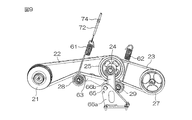
- 8 and 9 are perspective views showing the main part of the transmission mechanism 20 taken out, in particular, FIG. 8 is a view of the main part of the transmission mechanism as seen from the outside of the body, and FIG. 9 shows the main part of the transmission mechanism. It is the figure seen from the body inner side.
- the transmission mechanism 20 is located between the main pulley 21 mounted on the auxiliary output shaft 32 of the engine 30 and the sub pulley 27 mounted on the rotation input shaft 54 of the bevel gear 53, at a position close to the sub pulley 27. 2 is supported by a support base 66 fixedly disposed at the position 2.
- the support base 66 is provided with a first support portion 66a that supports the first tension pulley 28 fixed to the machine base 2, and a first support portion 66a that protrudes upward and is provided in a first manner.
- the intermediate pulley 25 and the second intermediate pulley 26 are configured to support the intermediate pulley 25 and the second intermediate pulley 26.
- the first support member 66a is composed of a pair of plate members provided facing each other at a predetermined distance in the width direction (left-right direction) of the machine base 2.
- Each plate member is formed in a substantially triangular shape (substantially trapezoidal shape) that inclines downward toward the rear so that the height of the front portion with respect to the rear is higher than the rear portion.
- a support shaft 65 is installed over the bridge.
- the first arm 63 is attached to the support shaft 65 so as to be rotatable around the support shaft 65 on the outer side of the first support member 66a.
- the first arm 63 is formed to extend toward the front of the machine base 2, and the first tension pulley 28 is rotatably supported at the tip of the first arm 63.
- the tip of the first arm 63 is connected to one end of a coil spring 61, and the other end of the coil spring 61 is connected to a rod 72 having a thread groove.
- FIGS. 6 and 7 show a rear right column 85 and a rear left column 86 of the boarding operation unit 40.
- Both pillars 85 and 86 are erected vertically upward from the machine base 2 and support the frame of the boarding operation unit 40 from below.
- a beam (beam) 87 is installed between the pillars 85 and 86 so as to pass the pillars 85 and 86 in the horizontal direction at a position approximately halfway between the boarding operation unit 40 and the machine base 2.
- the left end of the beam 87 is directly fixed to the rear left column 86, but the right end of the beam 87 is fixed via a support piece 88 for adjusting the longitudinal position attached to the rear right column 85. .
- the beam 87 is provided with a flange surface perpendicular to the direction in which the rod 72 extends, and a flange 73 in which a hole for inserting the rod 72 is formed on the flange surface is fixed.
- the rod 72 passes through the hole of the flange 73.
- a nut 74 is fitted into the thread groove of the rod 72 that has passed through the hole of the flange 73, and the nut 74 abuts on the flange 73. Therefore, the distance between the flange 73 and the coil spring 61 can be varied by turning and moving the nut 74.
- the first tension pulley 28 By fastening and fixing the nut 74 in a state where the coil spring 61 is extended, the first tension pulley 28 can be pulled up by the tensile elasticity of the coil spring 61. As a result, the first tension pulley 28 can be constantly pressed against the first belt 22 with a constant force, and the tension applied to the first belt 22 can be maintained at a constant value. Therefore, the rotation of the main pulley 21 is transmitted to the first intermediate pulley 25 with almost no loss.
- the lower part is fixed to the 1st support member 66a, and the bearing part formed in the hollow cylindrical shape is formed in the upper part.
- An intermediate shaft 24 is inserted into the bearing portion so as to protrude outward from the machine base 2.
- a first intermediate pulley 25, a second intermediate pulley 26, and a second arm 64 are rotatably mounted on the intermediate shaft 24 independently of each other. That is, the first intermediate pulley 25 and the second intermediate pulley 26 are configured to be rotatable between the bearing portion and the second arm 64.
- the second arm 64 is formed so as to extend rearward and downward of the machine base 2, and a support shaft 67 is provided at the tip thereof, and the second tension pulley 29 rotates on the support shaft 67. It is supported freely.
- the second tension pulley 29 can be switched between a state of contact with the second belt 23 so as to apply tension and a state of separation so as not to apply tension.
- the intermediate shaft 24 is rotating in the state, the power is transmitted to the rotation input shaft 54, while in the latter state, the power is not transmitted to the rotation input shaft 54 even if the intermediate shaft 24 is rotating.
- the position at which the first tension pulley 28 contacts the first belt 22 is closer to the intermediate shaft 24 than the position at which the second tension pulley 29 contacts the second belt 23. Set to a distant distance.
- the second tension pulley 29 When rotating the Glen tank 50, it is desirable to provide the second tension pulley 29 at a position close to the intermediate shaft 24 so as not to interfere with the Glen tank 50.
- the support member 66 is disposed at a position close to the sub pulley 27 as described above.
- the first belt 22 becomes longer than the second belt 23, but by extending the first arm 23 forward and supporting the first tension pulley 28, the first belt 22 becomes longer.
- the position at which the first tension pulley 28 contacts the belt 22 can be set to a substantially intermediate position of the first belt 22 (intermediate position in the front-rear direction of the machine base 2), and tension can be applied appropriately. It is.
- FIG. 10 is a right side view of the main part showing the boarding operation unit 40 and the transmission mechanism 20, and FIG. 11 is a plan view.
- one end of the coil spring 62 is wound around and attached to the support shaft 67 provided at the distal end portion of the second arm 64.
- a wire 75 is connected to the other end of the coil spring 62 as shown in FIG.
- the wire 75 is easy to bend and is made of a material having a large tensile strength, such as a metal wire, more specifically, an iron wire.
- the wire 75 is connected from the other end of the coil spring 62 to the arm 77 that can be moved up and down of the operation lever 42 installed in the operation box 76 disposed behind the driver seat 41.
- the driver can move the arm 77 up and down by operating the operation lever 42, thereby adjusting the tension of the wire 75.
- the tip of the second arm 64 can be pulled up or lowered via the wire 75.
- the distal end portion of the second arm 64 can be pulled up via the coil spring 62 by operating the operation lever 42 in the direction in which the wire 75 is pulled up.
- a force for pulling up the tip of the second arm 64 that is, a force for the second arm 64 to press the second belt 23.
- the value of this force is generally determined by the elasticity (spring constant) of the coil spring 62.
- a constant tension can be applied to the second belt 23 via the second tension pulley 29.
- the rotation of the second intermediate pulley 26 is transmitted to the sub pulley 27 with almost no loss.
- the driver operates the operation lever 42 in the direction in which the wire 75 is lowered, that is, in the direction in which the coil spring 62 is loosened, the force with which the tip of the second arm 64 comes into contact with the second belt 23 can be loosened. As a result, the tension of the second belt 23 can be relaxed. Therefore, the second belt 23 is loosened, and the loosened second belt 23 can be easily detached from the second intermediate pulley 26.
- the second arm 64 is arranged so as to be rotatable about the intermediate shaft 24 together with the first and second intermediate pulleys 25 and 26.
- the second arm 64 is supported on the common intermediate shaft 24.
- the second arm 64 may be supported by another support shaft provided on the support base 66 or another support base.
- a new support shaft need not be provided. There is an effect that the transmission device 20 can be reduced in weight and simplified in structure.
- the auxiliary output shaft 32 of the engine 30 is rotated by a pulley 33 for charging an alternator (not shown) and a radiator fan 35 for cooling the engine in addition to the main pulley 21.
- Pulleys (not shown) are also arranged, and a belt 34 for transmitting a rotational force to each of these pulleys is stretched.
- the tension applied to the second belt 23 can be relaxed by the driver operating the operation lever 42 and pushing down the wire 75.
- the second belt 23 can be removed from the secondary pulley 27 while the engine 30 is stopped.
- the slave pulley 27 can move freely with respect to the first and second intermediate pulleys 25 and 26 (the interlocked connection state is released), and the Glen tank 50 is removed.
- the lateral side portion of the threshing device 70 is opened in a wide space with the glen tank 50 opened by pulling out to one side in the machine body width direction or swinging (turning) left and right about a predetermined vertical axis. Can be maintained.
- the “predetermined vertical axis” may be the longitudinal axis of the vertical feed screw conveyor 52 when the vertical feed screw conveyor 52 linked to the bottom screw conveyor is provided at the rear of the Glen tank 50, for example. .
- the Glen tank 50 is opened around the vertical axis of the vertical feed screw conveyor 52
- the point P indicates the vertical axis of the vertical feed screw conveyor 52.
- the Glen tank 50 is provided so as to be relatively rotatable with respect to the vertical auger cylinder in which the vertical feed screw conveyor 52 is provided, and as shown in FIG. When it opens, the bottom screw conveyor 51, the bevel gear 53, the rotation input shaft 54, and the sub pulley 27 rotate together with the Glen tank 50.
- discharge cylinder 55 connected to the vertical auger cylinder, including the vertical auger cylinder, is also supported by the machine base 2 and remains in the machine base 2 without rotating together with the grain tank 50. There is also no increase in weight of 50.
- the Glen tank can be easily moved when the Glen tank 50 is pulled out to one side in the body width direction or swung to the left or right around a predetermined vertical axis.
- the sub pulley 27 can be made smaller in diameter.
- the diameter of the secondary pulley 27 is reduced, the rotational speed of the secondary pulley 27 can be adjusted by setting the diameter ratio D1 / D2 of the first and second intermediate pulleys 25 and 26 to a desired value. .
- the embodiment of the present invention has been described above, but the implementation of the present invention is not limited to the above-described embodiment.
- a combination of a pulley (without teeth) and a belt (V belt, flat belt, etc.) is used to transmit the rotational force by frictional force.
- a combination with a belt is also possible.
- the present invention can be carried out by replacing with other transmission members such as a roller chain instead of the toothed belt.
- various modifications can be made within the scope of the present invention.
Landscapes
- Life Sciences & Earth Sciences (AREA)
- Environmental Sciences (AREA)
- Engineering & Computer Science (AREA)
- Mechanical Engineering (AREA)
- Harvester Elements (AREA)
- Threshing Machine Elements (AREA)
- Combines (AREA)
Abstract
横向き姿勢のエンジン30と、グレンタンク内底部の底スクリューコンベア51の回転入力軸との間に伝動機構20を介装しているコンバインであって、エンジン30の出力軸32に装着された主プーリー21と、底スクリューコンベアの回転入力軸54に装着された従プーリー27と、機台に設置固定され互いに連動して回転する第1の中間プーリー25および第2の中間プーリー26と、主プーリー21と第1の中間プーリー25を連動させる第1の伝動部材22と、第2の中間プーリー26と従プーリー27とを連動させる第2の伝動部材23と、を備える。
Description
本発明は、エンジンからの動力を伝動する伝動機構を備えるコンバインに関する。
刈り取りながら脱穀する機能を備えたコンバインは、搭乗運転部と、刈取部と、刈取部からの穀稈を搬送する搬送部と、搬送された穀稈を脱穀する脱穀装置と、脱穀された穀稈を選別する選別装置と、選別された穀粒を回収するグレンタンクとを備えている。グレンタンクの内底部には、グレンタンクに溜まった穀粒を後部側に送る底スクリューコンベアはその軸芯が、車両走行方向の前後向きに沿って伸びて取付けられている。コンバインに動力を供給するエンジンは、搭乗運転部の下方に、その出力軸が車両走行方向の左右向き(横向き)になるように配備されている。エンジンは、出力軸の両端側から駆動力を取り出せるようになっており、走行装置、刈取部、脱穀装置、選別装置などを駆動する側の出力端を「主出力軸」といい、その反対側の出力端を「補助出力軸」と言うことにする。主出力軸は、コンバインの内部を向いており、補助出力軸はコンバインの外部、通常、コンバインの走行方向を向いて右側の側面カバーの下に隠れている。
補助出力軸は、特許文献1に記載されているように、ラジエータファンの回転軸を回転駆動するとともに、伝動機構およびベベルギヤを介して、底スクリューの回転入力軸と連結して、底スクリューに動力を伝えるように構成されている。
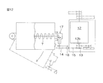
特許文献1に掲載された従来の伝動機構は、図12(上面図)に示すように、エンジン12の補助出力軸12bに装着された主プーリー13と、底スクリュー7のベベルギヤ17の回転入力軸に装着された従プーリー14と、2つのプーリーを連動させるベルト15と、ベルト15に張りを与えるために配置され、回動レバーによって入り切り可能なテンションクラッチ18とを備えている。
回動レバーを動かしてテンションクラッチ18を切り、伝動機構のベルト15を取り外すことによって、グレンタンクを横方向に引出したり、あるいは旋回揺動操作したりして、脱穀装置横側部のメンテナンスが行える。
グレンタンクの引出し操作もしくは旋回揺動操作をするに際して、回動レバーを移動させてテンションクラッチを切り、伝動機構のベルトを外すなどの各動作を、搭乗運転部の下からクローラ走行装置までの、部材が密集した狭い場所で行うことになる。
したがって、グレンタンクの移動を妨げないように、グレンタンクに装着されている各部材のサイズを極力小さくし、グレンタンク側の軽量化を図り、グレンタンクの移動に要する人力を軽減したいという要請がある。
前記グレンタンクに装着されている部材として、グレンタンク側の底スクリューのベベルギヤ回転入力軸に装着された従プーリーがあげられるが、できるだけ小径で軽量の従プーリーを採用することが望まれている。従プーリーの小型化、軽量化が実現できれば、グレンタンクの移動がしやすくなり、かつ、狭い場所で伝動機構のベルトを掛け外す作業も容易になると予想される。
そこで本発明の目的は、グレンタンクの移動操作が容易なように、グレンタンク側の小型化、軽量化が実現できる、伝動機構を備えるコンバインを提供することにある。
本発明のコンバインは、エンジンと、底スクリューコンベアを内設したグレンタンクと、エンジンの動力を底スクリューコンベアに伝動する伝動機構とを備える。伝動機構は、エンジンの出力軸に装着された主プーリーと、底スクリューコンベアの回転入力軸に装着された従プーリーと、機台に支持された支持台に互いに連動して回転する第1のプーリーおよび第2のプーリーと、主プーリーと第1のプーリーを連動させる第1の伝動部材と、第2のプーリーと従プーリーとを連動させる第2の伝動部材と、を有する。
以上の構成のコンバインでは、主プーリーと従プーリーとの間に第1のプーリーおよび第2のプーリーを設け、しかも、この第1のプーリーおよび第2のプーリーを、機台に固定された支持台に搭載している。この構成により、グレンタンク側に従プーリー以外の伝動機構を追加装備することなく、エンジンの出力軸に装着された主プーリーから、第1のプーリーおよび第2のプーリーを介して、グレンタンク側の従プーリーに対して所定の回転数の回転を伝えることができる。従プーリーの回転数は、第1のプーリーと第2のプーリーとの直径比を適宜設定することにより、任意の回転数とすることができる。また従プーリーの回転数を変えることなく、より小径、軽量にしたい場合は、第1のプーリーと第2のプーリーとの直径比を、第2のプーリーのほうが小さくなるように調節することで可能となる。
エンジンの出力軸がエンジンから機体外方に向けて突出しており、第2の伝動部材は、第1の伝動部材よりも機体外方に配置されている構成であれば、グレンタンクを取外し操作もしくは旋回揺動操作するに際して、伝動機構のベルトを容易に外すことができ、グレンタンクのメンテナンス時の取扱性を向上できる。
また、第1の伝動部材には第1のテンションクラッチが設けられるとともに、第2の伝動部材には第2のテンションクラッチが設けられ、第1および第2のテンションクラッチはともに支持台に支持されている構成であれば、グレンタンクを取外したり旋回揺動させたりする場合、テンションクラッチを切ってグレンタンクの底スクリューの駆動を切断することができる。その場合であっても第1のプーリーを設けているので、主プーリーから第1の伝動部材を介して伝動される第1のプーリーの回転を維持するようにすれば、回転駆動力を与えたい他の機械部品があれば、第1のプーリーと当該機械部品とを連動させることによって、常時、回転駆動力を与えることができる。
本発明によれば、グレンタンクの取外し操作もしくは旋回揺動操作に際して、グレンタンク側の軽量化とコンパクト化を実現できるという優れた効果を奏する。
本発明における上述の、またはさらに他の利点、特徴及び効果は、添付図面を参照して次に述べる発明の実施形態の説明により明らかにされる。
本実施の形態に係るコンバイン1は、図1から図3に外観を示すように、コンバイン1の機台2と、機台2の下部に連結され機台2を支える左右一対の走行クローラ100と、機台2に搭載され、コンバイン1が備える各部に動力を供給するエンジン30と、機台2の前部右側上方に載置された搭乗運転部40と、機台2の前方に昇降自在に連結された刈取部90と、機台2の左側上部に配置され刈取部90によって刈り取られた穀稈を脱穀処理する脱穀装置70と、脱穀装置70によって脱穀された穀粒を選別する選別装置80と、機台2の右側上部であって脱穀装置70の右側方、かつ、搭乗運転部40の後方に配置され、選別された穀粒を貯留するグレンタンク50とを備えている。さらにグレンタンク50の後方からコンバイン1の左側前方部にわたる範囲で脱穀装置70の上部に横たわっている排出筒55を備えている。なお、エンジン30、脱穀装置70、選別装置80、グレンタンク50等はコンバイン1の内部に設置されており、普段は機体カバーで囲われている。よって図1~図3に直接図示することはせず、おおよその位置を破線の引出線で示している。
搭乗運転部40は、機台2の前部でかつ機体幅方向の一方側に配置されており、グレンタンク50は、機台2の後部でかつ機体幅方向の一方側に配置されている。脱穀装置70や選別装置80は機台2の後部でかつ機体幅方向の他方側(グレンタンク50と反対側)に配置されている。なお、本実施の形態においては、機体幅方向の「一方側」とは、コンバイン1の前進方向を向いて右側を意味し、機体幅方向の「他方側」とは、コンバイン1の前進方向を向いて左側を意味する。
搭乗運転部40には、操縦者が着座可能な運転席41の前方に配置された操舵部材44、運転席41の後方に配置され、テンションプーリーを介してベルトの張力を調整するための操作レバー42など、種々の操作部材が備えられている。
エンジン30は、機台2の前部で、かつ搭乗運転部40の下方に配置されている。エンジン30の向きは、エンジン30の出力軸が機体幅方向と平行になるように配備されており、出力軸の両端側から駆動力を取り出せるようになっている。機体幅方向の他方側(機体内方側)から取り出す出力軸を「主出力軸」といい、機体幅方向の一方側(機体外方側)から取り出す(主出力軸の反対側の)出力軸を「補助出力軸」と言うことにする。主出力軸と補助出力軸とは、同じクランク軸につながっているので、同じ回転数で出力を取り出せる。
グレンタンク50の内底部は樋状に形成されており、当該樋状の内底部に沿って(機台の前後向きに沿って)、底スクリューコンベア51が配されている。底スクリューコンベア51の回転入力軸には、回転軸方向を直角に変換するためのベベルギヤ(後に図4を参照して説明する)が装着されている。
グレンタンク50の後部かつ、底スクリューコンベア51の排出端には底スクリューコンベア51の動力が伝動される縦送りスクリューコンベア52が、ほぼ垂直方向に配置されている。さらに縦送りスクューコンベア52からの穀粒を排出するコンベア式排出筒55がコンバイン1の機体上部に配されており、この排出筒55を油圧シリンダにより上下左右に揺動させることにより、穀粒を排出筒55から運搬車に積み込めるようにしてある。
機体幅方向の他方側に突出しているエンジン30の主出力軸31は、ベルト、チェーンなどの各種伝動部材を介して、主として、走行クローラ100、刈取部90、脱穀装置70、選別装置80を駆動する。
エンジン30の一方側、すなわち補助出力軸32のある側には、エンジン30を冷却するラジエータファン35(図6参照)が設置されているとともに、補助出力軸32の回転を底スクリューコンベア51に伝動するための伝動機構20が配置されている。
図1の符号43は、エンジン30を機体幅方向の一方側から覆う側面カバーを示し、この側面カバー43を取り外すことによって伝動機構20の一部を露出させることができる。
なお、本実施の形態では、回収された穀粒を送る底スクリューコンベア51を機台2の前後向きに設けているが、底スクリューコンベアが機台2の走行方向の左右向きに付いているコンベアに対しても本発明は適用できる。この場合、回転入力軸の方向が補助出力軸32の方向と同一方向(平行)になるので、底スクリューコンベア51の回転入力軸にベベルギヤが装着されない構成となるが、伝動機構20自体の構成は変わりない。
図4は、エンジンの補助出力軸32の回転を伝える動力伝動系を示す駆動系統図である。
伝動機構20は、エンジン30の補助出力軸32と底スクリューコンベア51の回転入力軸54との間に中間軸24を有し、さらに補助出力軸32に装着された主プーリー21と、中間軸24に装着され、互いに一体回転する第1、第2の中間プーリー25,26と、ベベルギヤ53の回転入力軸54に装着された従プーリー27と、を有する。そして、主プーリー21と第1の中間プーリー25との間に第1の伝動部材としての第1のベルト22が掛けられ、第2の中間プーリー26と従プーリー27との間に第2の伝動部材としての第2のベルト23が掛けられている。
なお、底スクリューコンベア51はもとより、そのベベルギヤ53およびその回転入力軸54、従プーリー27は、(機台2でなく)グレンタンク50側に取付けられている。
底スクリューコンベア51の回転出力軸の後端部は、ベベルギヤ56を介して、ほぼ垂直方向に配置された縦送りスクリューコンベア52の回転出力軸の下端部に連動連結されている。縦送りスクリューコンベア52の回転出力軸の上端部には、第1のプーリー対57a,57bおよびベベルギヤ58が連結されている。ベベルギヤ58の出力軸には、さらに第2のプーリー対59a,59bおよびベベルギヤ60が連結され、このベベルギヤ60の出力軸に、コンベア式排出筒55を構成する排出スクリューコンベア81の回転軸が連動連結される。このように縦送りスクリューコンベア52と排出スクリューコンベア81との間に、プーリー対およびベベルギヤを介在させたのは、縦送りスクリューコンベア52の回転軸と排出スクリューコンベア81の回転軸との間を、所定の距離だけ離間(オフセット)させるためである。オフセットさせた構造とすることにより、縦送りスクリューコンベア52および排出スクリューコンベア81の配置、設計の自由度を高めることができる。
本実施の形態では、第1の中間プーリー25と第2の中間プーリー26との位置関係は、第2のベルト23が掛かっている第2の中間プーリー26のほうが、第1の中間プーリー25よりも機体外方側に置かれるようにしている。よって、第2のベルト23が、第1のベルト22よりも機体外方に配置されることになる。後に説明するように、グレンタンク50を旋回揺動操作するとき、それに先立って第2のベルト23を取り外すことが必要になるが、その際に、この位置関係により、第2のベルト23を取り外す操作がしやすくなる。
本実施の形態では第1、第2の中間プーリー25,26は、同軸上で回転するようになっている。しかし、必ずしも同軸上に配置しなくてもよく、第1、第2の中間プーリー25,26は連動して回転するものであればよい。例えば第1の中間プーリー25の支軸と第2の中間プーリー26の支軸とが離れていてもよい。その場合、第1の中間プーリー25と第2の中間プーリー26とは互いにベルト、チェーンなどの連結部材によって連動連結される。しかし、第1、第2の中間プーリー25,26を同軸で一体に回転する構造を採用すれば、第1、第2の中間プーリー25,26を別々に設けるよりも、第1、第2の中間プーリー25,26の占める空間を小さくすることができるので、好ましい。
ここで第1の中間プーリー25の直径をD1、第2の中間プーリー26の直径をD2とすると、直径比D1/D2は任意に設定できる。本実施の形態では、好ましくは一方が他方よりも小さくなっている。さらに好ましくは、従プーリー27と連動する第2の中間プーリー26の直径D2のほうが主プーリー21と連動する第1の中間プーリー25の直径D1よりも、小さくなっている。これにより回転入力軸54の回転速度を補助出力軸32の回転速度よりも低速度とすることができる。
符号28,29は、それぞれ第1のベルト22、第2のベルト23に接触してベルトの張力を保つように設置された第1、第2のテンションプーリーを示す(後に図5~図8を参照して説明する)。
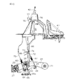
図5は、機台2の前部で、かつ機体幅方向の一方側の部分、すなわち搭乗運転部40の下方を見た要部平面図である。図6は、図5に示される同じ部分を機体幅方向の一方側から見た要部側面図である。図7は、搭乗運転部40と伝動機構20とを示す要部斜視図である。図8および図9は、伝動機構20の要部を取り出して示す斜視図であり、特に図8は伝動機構の要部を機体外方側から見た図、図9は伝動機構の要部を機体内方側から見た図である。
伝動機構20は、エンジン30の補助出力軸32に装着された主プーリー21とベベルギヤ53の回転入力軸54に装着された従プーリー27との間であって、従プーリー27に近い位置で機台2に固定配置された支持台66により支持されている。
より詳説すれば、支持台66は、機台2に固定された第1テンションプーリー28を支持する第1支持部66aと、第1支持部66aに支持されて上方に突出して設けられて第1の中間プーリー25及び第2の中間プーリー26を支持する第2支持部66bとから構成される。
第1支持部材66aは、機台2の幅方向(左右方向)に所定の距離を隔てて互いに対向して設けられた一対の板部材から構成される。各板部材は前部が後部に対して機台2に対する高さが高くなるように後方に向けて下方に傾斜する略三角形状(略台形状)に形成され、前部には両板部材に亘って支軸65が架設されている。
支軸65には、第1のアーム63が、第1支持部材66aの外側方で、支軸65を中心にして回動可能に取付けられている。第1のアーム63は機台2の前方に向かって伸びて形成されており、第1のテンションプーリー28は、第1のアーム63の先端部に回転自在に支承されている。この第1のアーム63の先端部は、コイルばね61の一端に接続され、コイルばね61の他端にはネジ溝の切られたロッド72が接続されている。
ロッド72の先端部を支持する構造を、図6、図7を用いて詳しく説明する。本実施の形態に係るコンバイン1には、搭乗運転部40を支える部材として、搭乗運転部支持用の柱が複数本設置されている。それらのうち、図6、図7に、搭乗運転部40の後部右の柱85と後部左の柱86とを示す。両柱85,86ともに、機台2から垂直上方に立設され、搭乗運転部40のフレームを下から支持している。搭乗運転部40と機台2とのほぼ中間の高さの位置に、両柱85,86を水平方向に渡すビーム(梁)87が、両柱85,86の間に設置されている。ここにおいて、ビーム87の左端は後部左の柱86に直接固定されているが、ビーム87の右端は後部右の柱85に取り付けられた前後位置調整用の支持片88を介して固定されている。
ビーム87には、ロッド72の延びる方向に対して垂直なフランジ面を提供するとともに、このフランジ面にロッド72を挿通させるための孔が形成されたフランジ73が固定されている。ロッド72は、このフランジ73の孔を通っている。フランジ73の孔を通ったロッド72のネジ溝には、ナット74が嵌合しており、このナット74がフランジ73に当接する。よってこのナット74を回して移動させることにより、フランジ73とコイルばね61との距離を可変することができる。コイルばね61が伸張した状態でナット74を締結固定することにより、コイルばね61の引っ張り弾力で第1のテンションプーリー28を引き上げることができる。この結果、第1のテンションプーリー28を一定の力で常時、第1のベルト22に押し付けることができ、第1のベルト22にかかる張力を一定の値に保つことができる。よって、主プーリー21の回転が第1の中間プーリー25にほとんど損失なく伝動される。
支持台66の第2支持部材66bは、下部が第1支持部材66aに固着され、上部は中空の円筒形状に形成された軸受部が形成されている。軸受部には機台2の外方に向けて突出するように中間軸24が挿設される。中間軸24には、第1の中間プーリー25、第2の中間プーリー26、第2のアーム64が互いに独立して回動可能に装着されている。つまり第1の中間プーリー25と第2の中間プーリー26は軸受部と第2のアーム64との間で回動可能に構成されている。
第2のアーム64は機台2の後方かつ下方に向かって伸びて形成されて、その先端部には支軸67が設けられており、第2のテンションプーリー29は、この支軸67に回転自在に支承されている。
当該構成において、第1のベルト22が主プーリー21と第1の中間プーリー25との間に巻きまわされることで、補助出力軸32の動力(回転力)が中間軸24に伝達され、中間軸24の回転に伴って第2の中間プーリー26が回転する。上述したように第1のテンションプーリー28は、常時、第1のベルト22に対して張力を与えるように接触しており、補助出力軸32が回転しているときには、必ずその動力が中間軸24に伝達される。
次に、第2のベルト23が第2の中間プーリー26と従プーリー27との間に巻きまわされることで、中間軸24の動力がベベルギヤ53の回転入力軸54に伝達され、回転入力軸54の回転に伴って、ベベルギヤ53を介して底スクリューコンベア51が駆動される。
ここで第2のテンションプーリー29は後述するように、第2のベルト23に対して張力を与えるように接触する状態と、張力を与えないように離間する状態とに切り替え可能であり、前者の状態において中間軸24が回転しているときはその動力を回転入力軸54に伝達する一方、後者の状態においては中間軸24が回転していてもその動力は回転入力軸54に伝達されない。
なお、本実施の形態では、第1のテンションプーリー28が第1のベルト22に接触する位置が、第2のテンションプーリー29が第2のベルト23に接触する位置に比べて、中間軸24から遠い距離に設定される。
グレンタンク50を回動するにあたって、第2のテンションプーリー29がグレンタンク50と干渉しないように中間軸24に近い位置に設けることが望ましい一方、当該構成において第2のベルト23を長尺とすると張力に緩みが生じてしまうおそれがあることから前述したように支持部材66を従プーリー27に近い位置に配置している。これに伴い、第1のベルト22は第2のベルト23に比べて長尺となってしまうが、第1のアーム23を前方に伸ばして第1のテンションプーリー28を支承することで、第1のベルト22において第1のテンションプーリー28が接触する位置を第1のベルト22の略中間位置(機台2の前後方向の中間位置)とすることができ、適切に張力を付与することが可能である。
図10は搭乗運転部40と伝動機構20とを示す要部右側面図であり、図11は平面図である。
本実施の形態では、第2のアーム64の先端部に設けられた支軸67に、コイルばね62の一端が巻回されて取付けられている。コイルばね62の他端には、図10に示すようにワイヤー75が接続されている。このワイヤー75は曲げるのが容易で、かつ大きな引っ張り強度を持つ材料、例えば金属線、より具体的には鉄線で構成されている。
ワイヤー75は、コイルばね62の他端から、運転席41の後方に配置された操作ボックス76に設置されている操作レバー42の上下動可能なアーム77まで接続されている。運転者は、操作レバー42を操作することによって、アーム77を上下動させることができ、これによりワイヤー75の張力を調整することができる。この結果として、ワイヤー75を介して、第2のアーム64の先端部を引き上げたり、下げたりすることができる。
より詳細に言えば、操作レバー42を、ワイヤー75を引っ張り上げる方向に操作することによって、コイルばね62を介して第2のアーム64の先端部を引き上げることができる。これによって、第2のアーム64の先端部を引き上げる力、すなわち第2のアーム64が第2のベルト23を押さえる力を発生させることができる。この力の値はおおむねコイルばね62の弾力(ばね定数)によって決まる。この結果、第2のテンションプーリー29を介して、第2のベルト23に一定の張力を与えることができる。この結果、第2の中間プーリー26の回転が従プーリー27にほとんど損失なく伝動される。
また、運転者が操作レバー42を、ワイヤー75を下げる方向、すなわちコイルばね62を緩める方向に操作すると、第2のアーム64の先端部が第2のベルト23に当接する力を緩めることができ、結果として第2のベルト23の張力を緩めることができる。よって、第2のベルト23が緩み、緩んだ第2のベルト23を第2の中間プーリー26から容易に取り外すことができる。
なお第2のアーム64は、本実施の形態では、第1、第2の中間プーリー25,26と共に中間軸24を中心にして回動可能に配置されているが、共通の中間軸24に支承されている必要は必ずしもなく、第2のアーム64が支持台66又は他の支持台に設けられた他の支軸に支承されるようにしてもよい。しかし本実施の形態のように、第1、第2の中間プーリー25,26の中間軸24を利用して第2のアーム64を支承すれば、新たに支軸を設けなくてもよくなり、伝動装置20の軽量化と構造の単純化が得られるという効果がある。
また、図6に示されているように、エンジン30の補助出力軸32には、主プーリー21のほかに、図示しないオルタネータを充電するためのプーリー33や、エンジンを冷却するラジエータファン35に回転を伝えるためのプーリー(図示せず)も配置されていて、これらの各プーリーに回転力を伝えるためのベルト34が張られている。
以上に述べたようなエンジン30の回転出力伝動装置の構成であるから、運転者が操作レバー42を操作してワイヤー75を押し下げることによって、第2のベルト23に加えられる張力を緩めることができ、エンジン30を止めた状態で、第2のベルト23を従プーリー27から取り外すことができる。第2のベルト23を従プーリー27から取り外すと、従プーリー27は第1、第2の中間プーリー25,26に対して自由に動けるようになり(連動連結状態が解除され)、グレンタンク50を機体幅方向の一方側に引き出したり、あるいは所定の垂直軸を中心に左右旋回揺動(回動)させたりして、グレンタンク50を開放した状態で、広い空間で脱穀装置70の横側部のメンテナンスが行える。前記「所定の垂直軸」とは、例えばグレンタンク50の後部に底スクリューコンベアに連動連結した縦送りスクリューコンベア52が設けられている場合、縦送りスクリューコンベア52の縦軸芯であってもよい。
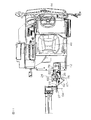
縦送りスクリューコンベア52の縦軸芯まわりにグレンタンク50を開放した場合について図4に基づいて説明する。図4において点Pは縦送りスクリューコンベア52の縦軸芯を示す。グレンタンク50は縦送りスクリューコンベア52を内設する縦オーガ筒に対して相対回動可能に設けられており、図4に示すように、グレンタンク50を縦軸芯Pを中心に外方に向かって開放するとグレンタンク50と共に、底スクリューコンベア51、ベベルギヤ53、回転入力軸54、及び、従プーリー27が回動する。
一方、図8、図9に示した機台2に固定された支持台66により支持された中間軸24および第1、第2の中間プーリー25,26ならびに第1のアーム63、第2のアーム64、第1、第2のテンションプーリー28,29は、グレンタンク50と共に回動せず機台2に残っており、これら構成によるグレンタンク50の重量の増加がない。
また、縦オーガ筒を含め、縦オーガ筒に連結されている排出筒55も機台2によって支持されていて、グレンタンク50と共に回動せず機台2に残っており、これら構成によるグレンタンク50の重量の増加もない。
よって、グレンタンク50を機体幅方向の一方側に引き出したり所定の垂直軸を中心に左右旋回揺動させる場合に、グレンタンクの移動操作が容易にできるようになる。
また、グレンタンク50を軽量化するために、従プーリー27を、より小径化することもできる。小径化した場合、グレンタンク50の移動操作をするに際して、従プーリー27がグレンタンクの移動の邪魔をするおそれのある周りの部材と衝突する可能性が減り、前記「周りの部材」を特に小型化しなくても、グレンタンクの移動空間を確保できるようになる。なお従プーリー27を小径化した場合、前記第1、第2の中間プーリー25,26の直径比D1/D2を所望の値に設定することにより、従プーリー27の回転数を調整することができる。
また本実施の形態では、機体に支持された中間軸24が存在するので、この中間軸24を利用して他の機械部品を回転駆動することも可能である。
以上で、本発明の実施の形態を説明したが、本発明の実施は、前記の形態に限定されるものではない。例えば、本実施の形態では、摩擦力により回転力を伝動するのに(歯のない)プーリーと、ベルト(Vベルト、平ベルトなど)との組み合わせを用いていたが、歯付きプーリーと歯付きベルトとの組み合わせとしてもよい。また歯付きベルトに代えて、ローラーチェーンなど、他の伝動部材で置き換えても本発明は実施できる。その他、本発明の範囲内で種々の変更を施すことが可能である。
本発明の実施形態について詳細に説明してきたが、これらは本発明の技術的内容を明らかにするために用いられた具体例に過ぎず、本発明はこれらの具体例に限定して解釈されるべきではなく、本発明の範囲は添付の請求の範囲によってのみ限定される。
本出願は、2017年6月16日に日本国特許庁に提出された特願2017-118783号に対応しており、当該出願の全開示は、引用により本出願に組み込まれるものとする。
1 コンバイン
2 機台
20 伝動機構
21 主プーリー
22 第1の伝動部材
23 第2の伝動部材
24 中間軸
25 第1の中間プーリー
26 第2の中間プーリー
27 従プーリー
28 第1のテンションプーリー
29 第2のテンションプーリー
30 エンジン
40 搭乗運転部
41 運転席
43 側面カバー
44 操作レバー
50 グレンタンク
51 底スクリューコンベア
53 ベベルギヤ
61,62 コイルばね
2 機台
20 伝動機構
21 主プーリー
22 第1の伝動部材
23 第2の伝動部材
24 中間軸
25 第1の中間プーリー
26 第2の中間プーリー
27 従プーリー
28 第1のテンションプーリー
29 第2のテンションプーリー
30 エンジン
40 搭乗運転部
41 運転席
43 側面カバー
44 操作レバー
50 グレンタンク
51 底スクリューコンベア
53 ベベルギヤ
61,62 コイルばね
Claims (3)
- エンジンと、底スクリューコンベアを内設したグレンタンクと、前記エンジンの動力を前記底スクリューコンベアに伝動する伝動機構とを備え、
前記グレンタンクは機台に対して取外し操作もしくは旋回揺動操作可能に設けられ、
前記伝動機構は、
前記エンジンの出力軸に装着された主プーリーと、
前記底スクリューコンベアの回転入力軸に装着された従プーリーと、
機台に支持された支持台に互いに連動して回転する第1のプーリーおよび第2のプーリーと、
前記主プーリーと前記第1のプーリーを連動させる第1の伝動部材と、
前記第2のプーリーと前記従プーリーとを連動させる第2の伝動部材と、
を有するコンバイン。 - 前記出力軸は前記エンジンから前記機体外方に向けて突出しており、前記第2の伝動部材は、前記第1の伝動部材よりも機体外方に配置されている、請求項1に記載のコンバイン。
- 前記第1の伝動部材には第1のテンションクラッチが設けられるとともに、前記第2の伝動部材には第2のテンションクラッチが設けられ、前記第1および第2のテンションクラッチは前記支持台に支持される、請求項1または請求項2に記載のコンバイン。
Applications Claiming Priority (2)
| Application Number | Priority Date | Filing Date | Title |
|---|---|---|---|
| JP2017118783A JP7116533B2 (ja) | 2017-06-16 | 2017-06-16 | コンバイン |
| JP2017-118783 | 2017-06-16 |
Publications (1)
| Publication Number | Publication Date |
|---|---|
| WO2018230163A1 true WO2018230163A1 (ja) | 2018-12-20 |
Family
ID=64660361
Family Applications (1)
| Application Number | Title | Priority Date | Filing Date |
|---|---|---|---|
| PCT/JP2018/016633 Ceased WO2018230163A1 (ja) | 2017-06-16 | 2018-04-24 | コンバイン |
Country Status (2)
| Country | Link |
|---|---|
| JP (1) | JP7116533B2 (ja) |
| WO (1) | WO2018230163A1 (ja) |
Cited By (1)
| Publication number | Priority date | Publication date | Assignee | Title |
|---|---|---|---|---|
| US20220348412A1 (en) * | 2021-04-30 | 2022-11-03 | Cnh Industrial America Llc | Electronically controlled viscous coupler for combine harvester |
Families Citing this family (1)
| Publication number | Priority date | Publication date | Assignee | Title |
|---|---|---|---|---|
| JP2021083322A (ja) * | 2019-11-25 | 2021-06-03 | 株式会社クボタ | 収穫機 |
Citations (4)
| Publication number | Priority date | Publication date | Assignee | Title |
|---|---|---|---|---|
| GB1444969A (en) * | 1972-10-27 | 1976-08-04 | Int Harvester Co | Control device for the grain delivery tube of a combine harvester |
| JPH06253666A (ja) * | 1993-03-05 | 1994-09-13 | Kubota Corp | コンバインの穀粒排出装置駆動部 |
| JPH09205868A (ja) * | 1996-02-06 | 1997-08-12 | Iseki & Co Ltd | グレンタンクの伝動支持装置 |
| JP2004105114A (ja) * | 2002-09-19 | 2004-04-08 | Seirei Ind Co Ltd | コンバインの穀粒排出オーガ装置 |
Family Cites Families (2)
| Publication number | Priority date | Publication date | Assignee | Title |
|---|---|---|---|---|
| JPH06930Y2 (ja) * | 1986-05-20 | 1994-01-12 | セイレイ工業株式会社 | グレンタンク駆動構造 |
| JP2011167094A (ja) | 2010-02-17 | 2011-09-01 | Yanmar Co Ltd | コンバイン |
-
2017
- 2017-06-16 JP JP2017118783A patent/JP7116533B2/ja active Active
-
2018
- 2018-04-24 WO PCT/JP2018/016633 patent/WO2018230163A1/ja not_active Ceased
Patent Citations (4)
| Publication number | Priority date | Publication date | Assignee | Title |
|---|---|---|---|---|
| GB1444969A (en) * | 1972-10-27 | 1976-08-04 | Int Harvester Co | Control device for the grain delivery tube of a combine harvester |
| JPH06253666A (ja) * | 1993-03-05 | 1994-09-13 | Kubota Corp | コンバインの穀粒排出装置駆動部 |
| JPH09205868A (ja) * | 1996-02-06 | 1997-08-12 | Iseki & Co Ltd | グレンタンクの伝動支持装置 |
| JP2004105114A (ja) * | 2002-09-19 | 2004-04-08 | Seirei Ind Co Ltd | コンバインの穀粒排出オーガ装置 |
Cited By (2)
| Publication number | Priority date | Publication date | Assignee | Title |
|---|---|---|---|---|
| US20220348412A1 (en) * | 2021-04-30 | 2022-11-03 | Cnh Industrial America Llc | Electronically controlled viscous coupler for combine harvester |
| US12150412B2 (en) * | 2021-04-30 | 2024-11-26 | Cnh Industrial America Llc | Electronically controlled viscous coupler for combine harvester |
Also Published As
| Publication number | Publication date |
|---|---|
| JP2019000056A (ja) | 2019-01-10 |
| JP7116533B2 (ja) | 2022-08-10 |
Similar Documents
| Publication | Publication Date | Title |
|---|---|---|
| JP6895875B2 (ja) | クローラ走行装置 | |
| US7159343B2 (en) | Working machine | |
| JP5916593B2 (ja) | コンバイン | |
| JP2019000056A (ja) | コンバイン | |
| JP5814535B2 (ja) | コンバイン | |
| JP2019004761A (ja) | コンバイン | |
| KR102120305B1 (ko) | 콤바인 | |
| JP5539749B2 (ja) | ステアバイワイヤ方式のコンバイン | |
| CN114173553B (zh) | 联合收割机 | |
| JP2009207503A (ja) | 田植機 | |
| JP6257479B2 (ja) | コンバイン | |
| JP6280785B2 (ja) | コンバインの穀粒排出装置 | |
| JP3952073B2 (ja) | コンバイン | |
| JP2021100433A (ja) | コンバイン | |
| JP2008295339A (ja) | コンバイン | |
| JP3907596B2 (ja) | コンバインの伝動構造 | |
| JP6524946B2 (ja) | コンバイン | |
| US12426538B2 (en) | Swing-out spreader for agricultural combines | |
| JP4778294B2 (ja) | コンバイン | |
| JP2014183808A (ja) | コンバイン | |
| JP2010004844A (ja) | コンバインのナローガイド | |
| JP7068833B2 (ja) | 収穫機 | |
| JP3831327B2 (ja) | コンバイン | |
| JP3736546B2 (ja) | コンバイン | |
| KR20160089258A (ko) | 링크기구를 이용한 일체형 정역회전 장치를 갖는 콤바인 |
Legal Events
| Date | Code | Title | Description |
|---|---|---|---|
| 121 | Ep: the epo has been informed by wipo that ep was designated in this application |
Ref document number: 18818528 Country of ref document: EP Kind code of ref document: A1 |
|
| NENP | Non-entry into the national phase |
Ref country code: DE |
|
| 122 | Ep: pct application non-entry in european phase |
Ref document number: 18818528 Country of ref document: EP Kind code of ref document: A1 |